Vertical Alignment. Concepts of design & guidelines Computing elevations along vertical curves Designing vertical curves
|
|
|
- Shana Blair
- 5 years ago
- Views:
Transcription
1 Vertical Alignment Concepts of design & guidelines Computing elevations along vertical curves Designing vertical curves
2 Flat terrain You can select smooth horizontal alignment and smooth vertical alignment
3 Rolling terrain It is relatively easy to find a good alignment in rolling terrain
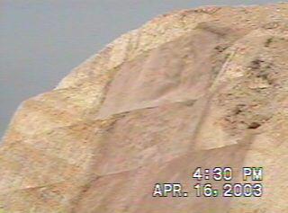
4 Mountainous terrain Relatively difficult to find good alignment Loose material on cut side slope

5 Mountainous terrain Extremely difficult to find good alignment in hilly areas
6 Mountainous terrain Extremely difficult to find good alignment in hilly areas
7 Sand dune areas It is difficult to design an alignment in sand dune areas
8 Main topics Main concepts in selecting a vertical alignment or road profile Determining design elevations along the road profile Designing vertical curves along the vertical alignment General controls for vertical alignments
9 General definitions The grade line is a reference line by which the elevation of the pavement and other features of the highway are established All portions of the grade line must meet sight distance requirements for the design speed classification of the road. The grade line is controlled mainly by the topography, type of highway, horizontal alignment, performance of heavy vehicles, right of way costs, safety, sight distance, construction costs, cultural development, drainage, and pleasing appearance.
10 Road profile Grade line or design profile Fill Cut Original ground level (OGL)
11 Working in cut section in soft rock (normal cut)
12 Working in cut section in solid rock (blasting)

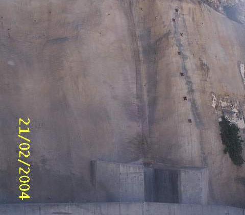
13 Finished cut side slope
14 Factors governing the road grade line 1. Earthwork quantities (cut & fill) 2. Control points (existing road, canal, water level, bridge, etc.) 3. Max & min grade 4. Critical length of the grade 5. Design speed & sight distance 6. General control of grade line 7. Coordination with horizontal alignment
15 Maximum grade Table 4.8 gives the max grade Upgrade: It limits the ability of vehicles to climb the upgrade (performance depends on the weight/horsepower ratio) Downgrade: It adds a driving force and speeding up, Downgrade: It adds a driving force and speeding up, pushes the vehicle outside the road, and/or causes a loss of control on the steering wheel.
16 Max grade
17 Example of steep gradient and sharp horizontal curves in mountainous terrain
18 Min grade is governed by the drainage conditions or requirements, especially in cut sections. Side ditch is required with cut section to drain water The minimum grade is used to facilitate draining the surface water in the longitudinal direction Minimum grade High qualify pavement: 0.35% Other types of pavements: 0.5% Avoid having sag curve with the lowest point in cut section
19 Critical length of grade It the maximum length of a given upgrade on which a loaded truck can operate without significant reduction in speed. Figure 4.15 gives the between the upgrade grade, length of grade, and the reduction of speed for 250 g/w truck. Figure 4.16 gives the relationship between the grade (up or down), length of grade, and the speed for 250 g/w truck.
20 Truck performance on upgrades Example: Truck starts moving on 4% with 60 km/h will reach, what is the critical length on this grade if maximum reduction in speed is 20 km/h?
21 Truck performance on downgrades
22 Climbing lanes When the reduction in speed is significant and road profile cannot be improved, a climbing lane should be used. It is not required in case of low traffic road. Function: to be used by slow trucks to facilitate the passing of light vehicles. Benefits: reduce accidents, reduce delay, improve section capacity and level of service. Length: should be determined based on the initial and final speed of truck. Transition length should be added at both ends of the climbing lane
23 Example of climbing lane 1. Truck starts to climb 5% grade at speed 60 km/h. This grade continues for about 400 m, and then followed by 1% grade for about 200 m and then by -1% for another 200 m. Determine the length of the climbing lane. 2. At the end of the 400 distance, the truck speed becomes about 25 km/h. After traveling 200 m on the 1% grade, truck speed reaches about 35 km/h. After traveling the 200 m on -1% grade, the truck speed reaches about 50 km/h 3. The climbing lane starts where the reduction in speed reaches 15 km/h (i.e., truck speed is 45 km/h) 4. This point is reached after the track travels ( ) or after traveling 160 m on the grade. 5. Use transition before this point 6. The climbing lane should end at a point where the truck re-gain at least its speed minus 15 km/h (i.e., truck speed reaches 45 km/h). 7. This sped is located on the -1% grade, after about 120 m on the grade. 8. Use a transition after this point 9. The length of the climbing lane is about = 560 m
24 g 2 g Types of vertical curves Crest (A=+ve) A= g 1 g 2 g 1 g Sag (A=- ve)
25 Difference in levels on grade 2 1 g g * X X E 2 = E 1 + g * X
26 Elements of vertical curves PC PI y + g x - g 2 1 L PT A= g 1 g 2 A is % or number K = e = Y L A A L A X = 200 L E x = E PC + g 1 * X - Y (Vertical curve parameter) A is number (External distance) A is number Vertical ordinate at distance (x) A is number Elevation on curve at distance (x) from PC Location of critical point on curve, measured from PC: Slope on curve at distance (X) from PC: Distance from PC where slope on curve equal (g ): Rate of change of gradient on vertical curve (r): X c 1 g x X = g ' g L = A = g g 1 1 m g A A X L r = 1/K = A/L ' L
27 Example 4% n -2% Given: L = 150 m, St PC = , Elev of PC = 20.5 m, St of n = , Req: a) Elev of n, b) Elev & Station of Highest point, c) station at g = 2%, d) slope at point n a) A= 6%, Y n = 6 * 30 2 /(200 * 150) = 0.18 m, Elev at n = *4/ = m b) X h = 4 * 150/ 6 = 100 m, Y h = 6* (100)2/ (200 * 150) = 2 m, Elev h = * 4/100 2 = = 22.5 (Also Elev h = = 22.5) c) X 2% = (4-2)/6 * 150 = 50 m, Y 2% = 6* (50) 2 / (200 * 150) = 0.5 m, Elev 2%= * 4/ = 22.5 m d) g = 4-6 * 30/150 = 2.8%
28 Sight distance on crest curve
29 Design of Crest curves for SSD h 2 h 1 S L General equations SSD Simplified equation S<L H1=1.05 m H2=0.15 m S>L
30 Design of Crest curves for PSD h 2 h 1 S L General equations PSD Simplified equation S<L H1=1.05 m H2=1.30 m S>L
31 Design of sag curves for SSD S H β L General equations SSD Simplified equation S<L H=0.6 m B =1 o m S>L


32 K Parameter of Vertical Curves
33 Example Given: 3%, -1% grades, Vd = 80 km/h A= 3% (-1%) = 4% S = 0.278*80* /(255*0.31)=136.6 m SSD = (calculated), 140 m (rounded) - (Table 4.1) PSD = 561 (calculated), 560 m (rounded) - (Table 4.4) Assume S<L L = A*S 2 /400 = 4*134 2 /400=179.6 m (L>S ok) For PSD: L = 4*560 2 /940 = m Note: for SSD, K=55, L= 4*55 = 220 m for PSD, K=235, L= 4*335 = 1340 m
34 Factors governing the vertical alignment Earthwork quantities (cut & fill) Control points (existing road, canal, water level, bridge, etc.) Max & min grade Critical length of the grade Design speed & sight distance
35 Additional factors controlling the vertical alignment a) A smooth grade line is better than a line with numerous breaks b) The roller-coaster or hidden dip should be avoided c) Broken back grade (two vertical curves in the same direction separated with short tangent) should be avoided not pleasing d) On long grade, it is preferred to put steepest grade at the bottom and least grade near top or to break grade by short interval of less grade e) At intersections, reduce gradient f) Climbing lane should be considered when critical length is exceeded and DHV exceeds capacity
36 a) Smooth grade line
37 b) Roller coaster


38 Local dip eliminated Local dip on long grade
39 d) Broken back grade Crest Sag
40 e) Steepest grade at bottom


41 Short hump and dip preceding horizontal curve
42 Out-of-phase vertical and horizontal alignments
43 Improper design of vertical alignment Where does the road go?
LIST OF FIGURES Figure Title
 TABLE OF CONTENTS Table of Contents... 1 List of Figures... 2 44-1A Critical Length of Grade for Trucks... 3 44-1B Critical Length of Grade for Recreational Vehicles... 3 44-1C Measurement for Length of
CHAPTER 6 VERTICAL ALIGNMENT
 CHAPTER 6 VERTICAL ALIGNMENT Introduction 6-3 Vertical Alignment Controls 6-3 Figure 6-1 Contrast of Poor Grade Line Design (Left) with Preferred Grade Line Design (Right) Figure 6-2 Example of a Hidden
Basic Road Design. If you don't know where you are going, any road will get you there. Lewis Carroll
 Basic Road Design If you don't know where you are going, any road will get you there. Lewis Carroll Road Design Horizontal alignment of a road defines its location and orientation in plan view. Vertical
200 Horizontal and Vertical Design. Table of Contents
 200 Horizontal and Vertical Design Table of Contents 201 Sight Distance... 2-1 201.1 General... 2-1 201.2 Stopping Sight Distance... 2-1 201.2.1 Horizontal Sight Distance... 2-2 201.2.2 Vertical Stopping
Section 4 Basic Geometric Design Elements
 4.1 General Section 4 Basic Geometric Design Elements BDC07MR-01 Geometric highway design pertains to the visible features of the highway. It may be considered as the tailoring of the highway to the terrain,
Geometric designs for Safe Highways. Dr. Manoj M. Asst. Professor Department of Civil Engineering IIT Delhi
 Geometric designs for Safe Highways Dr. Manoj M. Asst. Professor Department of Civil Engineering IIT Delhi WORKSHOP-CUM-TRAINING PROGRAMME ON ROAD SAFETY 17th 21st September 2018 Outline Introduction Cross
3-13 UFC - GENERAL PROVISIONS AND GEOMETRIC DESIGN FOR ROADS, STREETS, WALKS, AND OPEN
 maintenance, and erosion. Stability is required to maintain the integrity of the pavement structure, and a slope stability analysis should be conducted for cuts and fills greater than 15 feet. For lower
Alberta Infrastructure HIGHWAY GEOMETRIC DESIGN GUIDE AUGUST 1999
 Alberta Infrastructure HIGHWAY GEOMETRIC DESIGN GUIDE AUGUST 1999,1'(; A ACCELERATION Data on acceleration from stop D-29 Effects of grade D-35 Intersections D-97, D-99 Lanes D-97, F-5, F-7, F-15, F-21,
SECTION 1A NEW JERSEY TURNPIKE GEOMETRIC DESIGN
 SECTION 1A NEW JERSEY TURNPIKE GEOMETRIC DESIGN Table of Contents Page No 1A.1 GENERAL...1 1A.1.1 DESIGN CONTROLS...1 1A.2 MAINLINE ROADWAYS...4 1A.2.1 ROADWAY DESIGNATION...4 1A.2.2 DESIGN SPEED...4 1A.2.3
Chapter Twenty-eight SIGHT DISTANCE BUREAU OF LOCAL ROADS AND STREETS MANUAL
 Chapter Twenty-eight SIGHT DISTANCE BUREAU OF LOCAL ROADS AND STREETS MANUAL Jan 2006 SIGHT DISTANCE 28(i) Chapter Twenty-eight SIGHT DISTANCE Table of Contents Section Page 28-1 STOPPING SIGHT DISTANCE
Figure 1: Graphical definitions of superelevation in terms for a two lane roadway.
 Iowa Department of Transportation Office of Design Superelevation 2A-2 Design Manual Chapter 2 Alignments Originally Issued: 12-31-97 Revised: 12-10-10 Superelevation is the banking of the roadway along
GDOT Elements of Design. Course ID: GDOT PDH Credits
 GDOT Elements of Design Course ID: GDOT-06 3 PDH Credits Civil Engineer Educators LLC 1026 Timberwolf Lane Juneau, AK 99801 Email: support@civilpdh.com Chapter 4 Contents 4. ELEMENTS OF DESIGN 1 4.1. Sight
By: CHE ROS ISMAIL PROF DR MOHD ROSLI HAININ DR HARYATI YAACOB DR SITTI ASMAH HASSAN JGP-FKA, UTM
 By: CHE ROS ISMAIL PROF DR MOHD ROSLI HAININ DR HARYATI YAACOB DR SITTI ASMAH HASSAN JGP-FKA, UTM CONTENT 1. INTRODUCTION 2. STAGES OF HIGHWAY DEVELOPMENT 3. ROAD CATEGORY/CLASSIFICATION 4. DESIGN STANDARDS
Highway geometric design QUESTION PAPER
 QUESTION PAPER UNIT 1 1. Explain the design control and criteria which governs the design and highway. ( Dec 2011, june july 2011, June 2010, Dec 2010, Dec 2012) 2.Explain PCU value and factors affecting
ENGINEER S PRELIMINARY REPORT. for the #######-###### COLLISION
 ENGINEER S PRELIMINARY REPORT for the #######-###### COLLISION By: Lance E. Robson, P.E. October 3, 2005 1 INVESTIGATION OF THE #######-###### COLLISION ENGINEER S PRELIMINARY REPORT October 3, 2005 ---------------------------------------------------------------------------------------------------------------
October 2004 REVISIONS (2) SUPERELEVATION DEVELOPMENT 11.3(2)
 SUPERELEVATION DEVELOPMENT 11.3(2)") October 2004 REVISIONS (2) Chapter 11 HORIZONTAL ALIGNMENT SUPERELEVATION DEVELOPMENT 11.3(2) Chapter 12 VERTICAL ALIGNMENT VERTICAL CURVES PASSING SIGHT DISTANCE 12.5(2) VERTICAL CURVES STOPPING SIGHT
October 2004 REVISIONS (2) Chapter 11 HORIZONTAL ALIGNMENT SUPERELEVATION DEVELOPMENT 11.3(2) Chapter 12 VERTICAL ALIGNMENT VERTICAL CURVES PASSING SIGHT DISTANCE 12.5(2) VERTICAL CURVES STOPPING SIGHT
TABLE OF CONTENTS LIST OF FIGURES. Figure Title
 TABLE OF CONTENTS Table of Contents... 1 List of Figures... 1 Chapter Forty-two... 2 42-1.0 STOPPING SIGHT DISTANCE... 2 42-1.01 Theoretical Discussion...2 42-1.02 Passenger Car Stopping Sight Distance...
Dr. Naveed Anwar Executive Director, AIT Consulting Affiliated Faculty, Structural Engineering Director, ACECOMS
 Dr. Naveed Anwar Executive Director, AIT Consulting Affiliated Faculty, Structural Engineering Director, ACECOMS Overview Highway Functions and Classifications Highway Design Components Design Control
Progress Report on the Design and Planning of an Infrastructure Improvement Project for the Sunnyside TIF District (Phase II)
") Presentation to the CNRC Board of Directors Regular Meeting March 11, 2015 1 Agenda Preferred Alternate Refinement for University Avenue, 3rd Street, and Beverly Avenue Intersection Improvements validate
Presentation to the CNRC Board of Directors Regular Meeting March 11, 2015 1 Agenda Preferred Alternate Refinement for University Avenue, 3rd Street, and Beverly Avenue Intersection Improvements validate
This Chapter sets forth the minimum design, technical criteria and specifications to be used in the preparation of all roadway plans.
 4.1 GENERAL This Chapter sets forth the minimum design, technical criteria and specifications to be used in the preparation of all roadway plans. These Roadway Standards are for new construction and modification
DESIGN BULLETIN #66/2010
 DESIGN BULLETIN #66/2010 Highway Geometric Design Guide Chapter B, Climbing Lane Warrants for Two Lane Undivided and Four Lane Divided Highways - Revised Summary This Design Bulletin is being issued as
1.3.4 CHARACTERISTICS OF CLASSIFICATIONS
 Geometric Design Guide for Canadian Roads 1.3.4 CHARACTERISTICS OF CLASSIFICATIONS The principal characteristics of each of the six groups of road classifications are described by the following figure
Roadway Vertical Alignments
 Roadway Vertical Alignments by Gregory J. Taylor, P.E. INTRODUCTION This course summarizes and highlights the design of vertical alignments for modern roads and highways. The contents of this document
Geometric design is the process whereby the layout of the road in the terrain is designed to meet the needs of the road users.
 CHAPTER 3: GEOMETRIC DESIGN OF HIGHWAYS Geometric design is the process whereby the layout of the road in the terrain is designed to meet the needs of the road users. 3.1 Appropriate Geometric Standards
Geometric design deals with the dimensioning of the elements of highways, such
 CHAPTER 15 Geometric Design of Highway Facilities Geometric design deals with the dimensioning of the elements of highways, such as vertical and horizontal curves, cross sections, truck climbing lanes,
Road Design Guidelines for Low Impact to Hydrology *
 Five Counties Salmonid Conservation Program P.O. Box 2819 Weaverville, CA 96093 (530) 623-1351 Ext. 5 FAX (530) 623-1353 email: mlancaster@trinitycounty.org Road Design Guidelines for Low Impact to Hydrology
SIGHT DISTANCE GUIDELINES
 SIGHT DISTANCE GUIDELINES According to the 2011 AASHTO, 2011 MMUTCD, and Michigan Department of Transportation Guidelines PREPARED BY GEOMETRICS AND OPERATIONS UNIT TRAFFIC AND SAFETY April 22, 2015 Providing
Roadway Horizontal Alignment
 Roadway Horizontal Alignment Course No: C04-034 Credit: 4 PDH Gregory J. Taylor, P.E. Continuing Education and Development, Inc. 9 Greyridge Farm Court Stony Point, NY 10980 P: (877) 322-5800 F: (877)
201 Sight Distance... 1
 2 Horizontal and Vertical Design Table of Contents July 213 2.1 ntroduction...1 21 Sight Distance... 1 21.1 General...1 21.2 Stopping Sight Distance...1 21.2.1 Horizontal Sight Distance... 2 21.2.2 Vertical
Chapter V TRAFFIC CONTROLS. Tewodros N.
 Chapter V TRAFFIC CONTROLS www.tnigatu.wordpress.com tedynihe@gmail.com Lecture Overview Traffic markings Longitudinal markings Transverse markings Object markers and delineator Traffic signs Regulatory
City of Roseville Section 13 Design Standards. _Bikeways January 2016 SECTION 13 BIKEWAYS
 SECTION 13 BIKEWAYS 13-1 GENERAL The City of Roseville bikeway standards are designed to insure that transportation and recreational bikeways are constructed in a manner that would provide a safe and comfortable
Off-Road Facilities Part 1: Shared Use Path Design
 Off-Road Facilities Part 1: Shared Use Path Design Presentation by: Eric Mongelli, P.E. Tom Huber October 9, 2012 FOLLOW THE CONVERSATION ON TWITTER Toole Design Group is live tweeting this webinar @tooledesign
Road Safety Audit training course. Motorways - safety issues of the motorway design
 Road Safety Audit training course Motorways - safety issues of the motorway design Jesper Mertner, Road safety auditor, COWI A/S 1 ROAD SAFETY AUDITING COURSE Content 1. Safety 2. Cross sections 3. Horizontal
Introduction to Roadway Design
 Chapter Introduction to Roadway Design 1 This chapter lays the foundation for the Roadway Design course. You examine the roadway design workflow and the completed drawing files and review the project scope,
Roadway Vertical Alignments
 Course No: C04-031 Credit: 4 PDH Gregory J. Taylor, P.E. Continuing Education and Development, Inc. 9 Greyridge Farm Court Stony Point, NY 10980 P: (877) 322-5800 F: (877) 322-4774 info@cedengineering.com
Roadway Horizontal Alignment Design
 Roadway Horizontal Alignment Design by Gregory J. Taylor, P.E. INTRODUCTION This course summarizes and highlights the design of horizontal alignments for modern roads and highways. The contents of this
ENGINEERING STANDARD FOR GEOMETRIC DESIGN OF ROADS AND STREETS ORIGINAL EDITION MAR. 1996
 ENGINEERING STANDARD FOR GEOMETRIC DESIGN OF ROADS AND STREETS ORIGINAL EDITION MAR. 1996 This standard specification is reviewed and updated by the relevant technical committee on Dec. 2000(1) and July.
Figure 3B-1. Examples of Two-Lane, Two-Way Marking Applications
 Figure 3B-1. Examples of Two-Lane, Two-Way Marking Applications A - Typical two-lane, two-way marking with passing permitted in both directions B - Typical two-lane, two-way marking with no-passing zones
FREEWAY WORK ZONE SPEED MODEL DOCUMENTATION
 APPENDIX B FREEWAY WORK ZONE SPEED MODEL DOCUMENTATION B-1 APPENDIX B FREEWAY WORK ZONE SPEED MODEL DOCUMENTATION B.1 INTRODUCTION This software can be used for predicting the speed of vehicles traveling
Design Criteria. Design Criteria
 F Design Criteria Design Criteria Ministry of Transportation Ministère des Transports DESIGN CRITERIA Page: 1 of 13 WORK PROJECT NO. N/A GO Bloomington Station TYPE OF PROJECT LOCATION Bloomington Road
Tonight we will be discussing accidents
 Good evening PRAG members WELCOME BACK SAFETY ON HANA HIGHWAY NEAR PAIA Tonight we will be discussing accidents Safety is a Top Priority One of the top priority Goals and objectives of this project is
Roadway Design Manual
 Roadway Design Manual Manual Notice Archive by Texas Department of Transportation (512) 302-2453 all rights reserved Manual Notice 2009-1 From: Manual: Mark A. Marek, P.E Roadway Design Manual Effective
INDEX. Geometric Design Guide for Canadian Roads INDEX
 Acceleration lane, see Lanes, Acceleration Access, 8.1 Access Management and Functional Classification 8.2 Access Management by Design Classification 8.3 Access Configuration 8.4 Building Set-Back Guidelines
Geometric Design Tables
 Design Manual Chapter 5 - Roadway Design 5C - Geometric Design Criteria 5C-1 Geometric Design Tables A. General The following sections present two sets of design criteria tables - Preferred Roadway Elements
MICHIGAN DESIGN MANUAL
 CHAPTER 3 INDEX ALIGNMENT AND GEOMETRICS 3.01 REFERENCES 3.02 DEFINITION OF TERMS 3.03 ALIGNMENT - GENERAL A. Horizontal Alignment B. Vertical Alignment C. Combined 3.03.01 Horizontal Alignment - Design
IH 20 RANGER HILL PUBLIC MEETING
 IH 20 RANGER HILL PUBLIC MEETING AUGUST 25, 2015 IH 20, Eastland County, TX CSJ 0007-06-084 IH 20 from 3.5 mi. East of LP 254 to SH 16 (Ranger Hill) August 25, 2015 Agenda Introductions Purpose of the
Designing and Benchmarking Mine Roads for Safe and Efficient Haulage. Roger Thompson Alex Visser
 Designing and Benchmarking Mine Roads for Safe and Efficient Haulage Roger Thompson Alex Visser Departments of Mining and Civil & Bio-systems Engineering University of Pretoria, South Africa Aim of Presentation
Friday, May 20, :46 PM Cambria N Armstrong Fw: Wolf Creek REV.pdf
 David Johnson From: Sent: To: Cc: Subject: Attachments: Thomas Malecek Friday, May 20, 2011 12:46 PM david@westerneco.com Cambria N Armstrong Fw: Wolf Creek 05-16-11 REV.pdf David,
Chapter III Geometric design of Highways. Tewodros N.
 Chapter III Geometric design of Highways Tewodros N. www.tnigatu.wordpress.com tedynihe@gmail.com Introduction Appropriate Geometric Standards Design Controls and Criteria Design Class Sight Distance Design
Off-road Trails. Guidance
 Off-road Trails Off-road trails are shared use paths located on an independent alignment that provide two-way travel for people walking, bicycling, and other non-motorized users. Trails specifically along
This update addresses several minor corrections and omissions in the English Road Design Manual (in dual units).
.") DISTRIBUTION: 91 MINNESOTA DEPARTMENT OF TRANSPORTATION DEVELOPED BY: Design Standards ISSUED BY: Office of Technical Support Design Services Section TRANSMITTAL LETTER NO. (11-01) MANUAL: Road Design
DISTRIBUTION: 91 MINNESOTA DEPARTMENT OF TRANSPORTATION DEVELOPED BY: Design Standards ISSUED BY: Office of Technical Support Design Services Section TRANSMITTAL LETTER NO. (11-01) MANUAL: Road Design
DESIGN MEMORANDUM WITH DESIGN EXCEPTIONS SP SP
 DRAFT NOT FINAL (Note: document was not finalized due to an eastbound stopping site distance design issue that requires more detailed bridge and roadway design considerations. This discussion starts on
Field Guide for Unpaved Rural Roads
 Field Guide for Unpaved Rural Roads Funded by the Federal Highway Administration Local Technical Assistance Program (LTAP) Developed by the Wyoming Technology Transfer (T2) Center, March 1997 Updated by
The City of Sault Ste. Marie Cycling Master Plan
 4.0 DESIGN GUIDELINES - Development This section provides direction to those who will be constructing trails in the future. The contents are technical, providing facility types and locations, construction
Sight Distance. The availability of sufficient sight distance for the driver to see ahead is critical to the design of a safe highway.
 Sigt Distance Te availability of sufficient sigt distance for te driver to see aead is critical to te design of a safe igway. Wat is sigt distance? Sigt distance is te lengt of igway visible to a driver.
Alberta Highway 881. Corridor Management Plan. Session Forum 1 - Highways. Tri-Party Transportation Conference Moving Alberta Into the Future
 Tri-Party Transportation Conference Moving Alberta Into the Future Alberta Highway 881 Corridor Management Plan Lac La Biche to Anzac Session Forum 1 - Highways March 2017 INTRODUCTION + 241 km long, 2
T R A N S P O R T A T I O N M E M O R A N D U M
 WILKINSON LLC t raffic engineering and t ransportation p lanning 3405 Harbor Way Fort Collins, CO 80524 phone: 970-988-0143 fax: 970-472-0223 martinawilkinson@msn.com T R A N S P O R T A T I O N M E M
An International Experience on the Safety Performance of 2+1 cross-section. Basil Psarianos Nat l Techn. Univ. Athens, Greece
 An International Experience on the Safety Performance of 2+1 cross-section Basil Psarianos Nat l Techn. Univ. Athens, Greece bpsarian@mail.ntua.gr What is a 2+1 cross-section? It s a 3 lane rural road
WYDOT DESIGN GUIDES. Guide for. Non-NHS State Highways
 WYDOT DESIGN GUIDES Guide for Non-NHS State Highways 2014 GUIDE FOR Non-NATIONAL HIGHWAY SYSTEM (Non-NHS) STATE HIGHWAYS PRESERVATION REHABILITATION RECONSTRUCTION INTRODUCTION This Guide is directed to
Access Management Standards
 Access Management Standards Section 1: Application of Access Standards This chapter describes the Department's access management standards for access connections on the county roadway system. The standards
Transportation Knowledge
 FE REVIEW COURSE SPRING 2017 Transportation Engineering 4/26/2017 Transportation Knowledge 8-12 problems Traffic safety Traffic capacity Traffic flow theory Traffic control devices Transportation planning
Policy Statement. Objective. Context. References and Supporting Documentation
 Policy Statement Subject Placement of Distribution Poles Along Roads With Speed Limits Not Exceeding 70km/h Approved by Robert Rogerson Signature & Date Distribution Standards and Policy Manager Authorised
Truck Climbing Lane Traffic Justification Report
 ROUTE 7 (HARRY BYRD HIGHWAY) WESTBOUND FROM WEST MARKET STREET TO ROUTE 9 (CHARLES TOWN PIKE) Truck Climbing Lane Traffic Justification Report Project No. 6007-053-133, P 101 Ι UPC No. 58599 Prepared by:
STATE HIGHWAY GEOMETRIC DESIGN MANUAL APPENDIX A: DESIGN CHECKLIST
 STATE HIGHWAY GEOMETRIC DESIGN MANUAL A - 1 Appendix A: Design Checklist for the Development of Geometric Plans (For use in the Planning and Design of State Highway Improvement Projects) NOTES: 1. Design
SECTION 12 ROAD MARKINGS AND DELINEATION
 SECTION 12 ROAD MARKINGS AND DELINEATION (Blank Page) MANUAL OF TRAFFIC SIGNS AND MARKINGS - Part III: Motorways and Expressways 12-1 12.1 GENERAL 12.1.1 INTRODUCTION The markings and delineation details
Paul Huston, P.E., Design-Build Coordinator Chuck Gonderinger, HDR Engineering. Minnesota Department of Transportation (the Department)
") To: From: Paul Huston, P.E., Design-Build Coordinator Chuck Gonderinger, HDR Engineering Date: March 20, 2001 Subject: Roadway Geometric Design Criteria Project: TH 14/218 Design-Build Project, SP 7408-29,
To: From: Paul Huston, P.E., Design-Build Coordinator Chuck Gonderinger, HDR Engineering Date: March 20, 2001 Subject: Roadway Geometric Design Criteria Project: TH 14/218 Design-Build Project, SP 7408-29,
How Might Connected Vehicles and Autonomous Vehicles Influence Geometric Design? October 10, 2017
 How Might Connected Vehicles and Autonomous Vehicles Influence Geometric Design? October 10, 2017 Overview Design Vehicle Design Driver Potential Geometric Impacts of Autonomous Vehicles Connected Vehicles
(HIGHWAY GEOMETRIC DESIGN -1)
") LECTURE HOUR-19 TE-1(10CV56) UNIT-3 (HIGHWAY GEOMETRIC DESIGN -1) Width of carriage way: Width of the carriage way or the width of the pavement depends on the width of the traffic lane and number of lanes.
LECTURE HOUR-19 TE-1(10CV56) UNIT-3 (HIGHWAY GEOMETRIC DESIGN -1) Width of carriage way: Width of the carriage way or the width of the pavement depends on the width of the traffic lane and number of lanes.
Review of Guidelines for Cycleway Safety Fencing
 Review of Guidelines for Cycleway 1.0 PURPOSE 1.1 This document is meant to provide a review of available reference documents for determining appropriate fencing requirements for cycleway paths and shared
To position power poles a safe distance from the road to minimise the likelihood of being accidentally hit by vehicles.
 Policy Statement Subject Placement of Rigid Distribution Poles Along Roads With Speed Limits Exceeding 70KM/H Approved by Robert Rogerson Signature & Date Distribution Standards and Policy Manager Authorised
DISTRIBUTION: Electronic Recipients List TRANSMITTAL LETTER NO. (17-01) MINNESOTA DEPARTMENT OF TRANSPORTATION. MANUAL: Road Design English Manual
 MINNESOTA DEPARTMENT OF TRANSPORTATION. MANUAL: Road Design English Manual") DISTRIBUTION: Electronic Recipients List MINNESOTA DEPARTMENT OF TRANSPORTATION DEVELOPED BY: Design Standards Unit ISSUED BY: Office of Project Management and Technical Support TRANSMITTAL LETTER NO.
DISTRIBUTION: Electronic Recipients List MINNESOTA DEPARTMENT OF TRANSPORTATION DEVELOPED BY: Design Standards Unit ISSUED BY: Office of Project Management and Technical Support TRANSMITTAL LETTER NO.
INTERSECTIONS AT GRADE INTERSECTIONS
 INTERSECTIONS 1 AT GRADE INTERSECTIONS INTERSECTIONS INTERSECTIONS = INTERRUPTED FACILITIES Definitions and key elements An intersection is defined as an area where two or more roadways join or cross.
Module 5: Navigating Roadways
 Module 5: Navigating Roadways Topic 1: Intersections 1. One out of FATAL crashes occur at intersections. 2. Label the intersection warning signs: 3. When possible, begin searching seconds ahead of the
September 2008 REVISIONS (1) SYMMETRICAL VERTICAL CURVE EQUATIONS 12.5(12) VERTICAL CURVE COMPUTATIONS 12.5(14) TURNING LANE LENGTHS 15.
 SYMMETRICAL VERTICAL CURVE EQUATIONS 12.5(12) VERTICAL CURVE COMPUTATIONS 12.5(14) TURNING LANE LENGTHS 15.") September 2008 REVISIONS (1) CHAPTER 12 VERTICAL ALIGNMENTS SYMMETRICAL VERTICAL CURVE EQUATIONS 12.5(12) VERTICAL CURVE COMPUTATIONS 12.5(14) CHAPTER 15 INTERSECTIONS TURNING LANE LENGTHS 15.5(10) CHAPTER
September 2008 REVISIONS (1) CHAPTER 12 VERTICAL ALIGNMENTS SYMMETRICAL VERTICAL CURVE EQUATIONS 12.5(12) VERTICAL CURVE COMPUTATIONS 12.5(14) CHAPTER 15 INTERSECTIONS TURNING LANE LENGTHS 15.5(10) CHAPTER
ADA Training Standard Plans
 ADA Training Standard Plans SCREEN READABLE VERSION IS IN THE MAKING AND WILL BE MADE AVAILABLE SOON 2018 MnDOT 2 Standard Plans 2017 Overview Overview PROWAG and Curb Ramp Basics Curb Ramp Types ADA Curb
WYDOT DESIGN GUIDES. Guide for. NHS Arterial (Non-Interstate)
") WYDOT DESIGN GUIDES Guide for NHS Arterial (Non-Interstate) 2014 GUIDE FOR NATIONAL HIGHWAY SYSTEM (NHS) HIGHWAYS (NHS ARTERIALS, Non-Interstate) PRESERVATION REHABILITATION RECONSTRUCTION INTRODUCTION
WYDOT DESIGN GUIDES Guide for NHS Arterial (Non-Interstate) 2014 GUIDE FOR NATIONAL HIGHWAY SYSTEM (NHS) HIGHWAYS (NHS ARTERIALS, Non-Interstate) PRESERVATION REHABILITATION RECONSTRUCTION INTRODUCTION
Non-Motorized Overpass at SR 5/US1
 Non-Motorized Overpass at SR 5/US1 And SR 97/SW th Street (Bird Road) Executive Summary March 9, 17 Prepared By: MARLIN Engineering Inc 17 NW th Avenue, Ste. 1 Plantation, FL 33313 P: 35.77.7575 www.marlinengineering.com
THE FUTURE OF THE TxDOT ROADWAY DESIGN MANUAL
 THE FUTURE OF THE TXDOT ROADWAY DESIGN MANUAL Kenneth Mora, P.E. (Design Division) 10/10/2017 Table of contents 1 2 Reduction in FHWA design controlling criteria Innovative Intersection Guidance 3-7 8-42
Driveway Design Criteria
 Design Manual Chapter 5 - Roadway Design 5L - Access Management 5L-4 Driveway Design Criteria A. General For efficient and safe operations, access drives and minor public street intersections can be improved
Parks Highway: MP Lucus Road to Big Lake Road
 2 Purpose and Need 2.1 Corridor History The Parks Highway is a 324-mile long Rural Interstate Highway that extends from its intersection with the Glenn Highway north to Fairbanks, Alaska. The Parks Highway
Bridge Design Preliminary Bridge Design Example 1 / 6 Spring 2012 updated 1/27/2012
 Bridge Design Preliminary Bridge Design Example 1 / 6 Perform a preliminary design for a bridge on a state highway over a large creek in rural Alabama. Produce a construction layout drawing showing profile
RURAL HIGHWAY SHOULDERS THAT ACCOMMODATE BICYCLE AND PEDESTRIAN USE (TxDOT Project ) June 7, Presented by: Karen Dixon, Ph.D., P.E.
 June 7, Presented by: Karen Dixon, Ph.D., P.E.") RURAL HIGHWAY SHOULDERS THAT ACCOMMODATE BICYCLE AND PEDESTRIAN USE (TxDOT Project 0-6840) June 7, 2016 Presented by: Karen Dixon, Ph.D., P.E., TTI Team: Kay Fitzpatrick, Raul Avelar, & Subasish Das Project
RURAL HIGHWAY SHOULDERS THAT ACCOMMODATE BICYCLE AND PEDESTRIAN USE (TxDOT Project 0-6840) June 7, 2016 Presented by: Karen Dixon, Ph.D., P.E., TTI Team: Kay Fitzpatrick, Raul Avelar, & Subasish Das Project
FOR HISTORICAL REFERENCE ONLY
 To: From: Subject: Electronic Distribution Recipients MINNESOTA DEPARTMENT OF TRANSPORTATION Engineering Services Division Technical Memorandum No. 12-14-B-03 December 18, 2012 Jon M. Chiglo, P.E. Division
* BLACK TRIANGLES Correct Answer. * RED TRIANGLES Red / blue circles. * BLUE RECTANGLES Explanation
 1 YOU MUST OBEY SIGNS GIVING ORDERS. THESE SIGNS ARE MOSTLY IN * BLACK TRIANGLES Correct Answer * RED TRIANGLES Red / blue circles. * BLUE RECTANGLES Explanation * RED / BLUE CIRCLES Traffic signs can
Design of Turn Lane Guidelines
 Design of Turn Lane Guidelines CTS Transportation Research Conference May 24, 2012 Howard Preston, PE Minnesota Department of Transportation Research Services Office of Policy Analysis, Research & Innovation
ADJUSTING TO, FOLLOWING, AND MEETING URBAN TRAFFIC
 Lesson 4 Student Notes 1 ADJUSTING TO, FOLLOWING, AND MEETING URBAN TRAFFIC 1. What two main factors make city driving difficult? There are more cars, buses, trucks, and pedestrians per mile. City hazards
Rural design meeting Oslo, 2011
 Rural design meeting Oslo, 2011 Randi Eggen Norwegian Public Road Administration (NPRA) Traffic Safety, Environment and Technology Department Section: Transport Planning Participants Germany: Netherlands:
CHAPTER 1 STANDARD PRACTICES
 CHAPTER 1 STANDARD PRACTICES OBJECTIVES 1) Functions and Limitations 2) Standardization of Application 3) Materials 4) Colors 5) Widths and Patterns of Longitudinal Pavement Marking Lines 6) General Principles
GEOMETRIC DESIGN STANDARDS FOR NEW RESIDENTIAL SUBDIVISION STREETS TABLE 1A CG-6 CURB AND GUTTER SECTION
 TABLE 1A CG-6 CURB AND GUTTER SECTION HORIZONTAL AND VERTICAL CONTROLS CURB AND GUTTER ROADWAYS MAXIMUM 3:1 CUT OR FILL SLOPE CURVE DATA MIN. SIGHT DISTANCE PROJECTED TRAFFIC VOLUME (ADT) MIN. DESIGN SPEED
PERFORMANCE ACTIVITY 306 DRAINAGE PIPE WORK DESCRIPTION 4
 PERFORMANCE ACTIVITY 306 DRAINAGE PIPE WORK DESCRIPTION 1 WORK DESCRIPTION 2 WORK DESCRIPTION 3 WORK DESCRIPTION 4 Repair Install Remove Clean 306 DRAINAGE PIPE ACTIVITY DESCRIPTION Install, repair, clean,
APPENDIX A SECTION A-1-GEOMETRIC DESIGN STANDARDS
 APPENDIX A SECTION A-1-GEOMETRIC DESIGN STANDARDS Introduction... A-1 Flexibility In Design... A-1 Secondary Project Improvements... A-2 Roadway Width... A-3 Design Speed (V)... A-3 Operating Speed...
AGENDA REPORT. Issue: Discussion of potential improvements on Barnwell Road at Niblick Drive
 AGENDA REPORT To: From: By: Honorable Mayor and City Council Members Warren Hutmacher, City Manager Tom Black, Public Works Director Date: March 23, 2016 Agenda: March 28, 2016 WORK SESSION AGENDA: Barnwell
Field guide for Accessible Public Rights-of-Way Edition
 Field guide for Accessible Public Rights-of-Way 2017 Edition CONTENTS PEDESTRIAN FACILITIES IN THE PUBLIC RIGHT-OF-WAY Pedestrian access routes 3 Components 3 Continuous width 3 Median and pedestrian refuge
DETECTABLE WARNING SURFACES SHALL BE PROVIDED AT THE FOLLOWING LOCATIONS ON PEDESTRIAN ACCESS ROUTES:
 GENERAL NOTES: CURB NOTES: 5'-0" MIN 5'-0" 5'-0" MIN 1. 2. THESE SHEETS ARE IN ACCORDANCE WITH THE AMERICANS WITH DISABILITIES ACT (ADA), AND THE REQUIREMENTS OF THE 2011 PROPOSED ACCESSIBILITY GUIDELINES
SECTION A-1-GEOMETRIC DESIGN STANDARDS
 APPENDIX A SECTION A-1-GEOMETRIC DESIGN STANDARDS Introduction... A-1 Flexibility In Design... A-1 Secondary Project Improvements... A-2 Roadway Width... A-3 Design Speed (V)... A-3 Operating Speed...
SECTION A-1-GEOMETRIC DESIGN STANDARDS
 APPENDIX A SECTION A-1-GEOMETRIC DESIGN STANDARDS Introduction... A-1 Flexibility In Design... A-1 Secondary Project Improvements... A-2 Roadway Width... A-3 Design Speed (V)... A-3 Operating Speed...
Signs. signs, signals and road markings. in this chapter
 3 signs, signals and road markings in this chapter Signs regulatory signs school, playground and crosswalk signs lane use signs turn control signs parking signs reserved lane signs warning signs object
Chapter 14 Challenging Driving Conditions
 Chapter 14 Challenging Driving Conditions 14-1 REDUCED VISIBILITY A. Complete each of the following sentences by writing the correct word or phrase in the space provided. 1. percent of a driver s ability
Road Safety Facilities Implemented in Japan
 Road Safety Facilities Implemented in Japan 1 Road Safety Facilities 1.Guard Fence 2.Road Lighting 3.Other Road Safety Facilities 2 Road Safety Facilities 1.Guard Fence 2.Road Lighting 3.Other Road Safety
Roadway Design Manual
 Roadway Design Manual Revised December 2013 2013 by Texas Department of Transportation (512) 302-2453 all rights reserved Manual Notice 2013-1 From: Manual: Mark A. Marek, P.E Roadway Design Manual Effective