Part 1 General Information Part 2 Outdoor Units... 8
|
|
|
- Jane Floyd
- 5 years ago
- Views:
Transcription
1 Contents Part 1 General Information... 1 Part 2 Outdoor Units... 8 Part 3 Installation Part 4 Part 5 Trouble shooting 99 Control system. 126 Manufacture reserves the right to discontinue, or change at any time, specifications or designs without notices and without incurring obligations. Contents
2
3 Part 1 General Information 1. Product Lineup Nomenclature Features... 4 General Information 1


4 1. Product Lineup Outdoor Units Model name Dimension body(mm) Net/Gross weight (kg) Power supply 38VR003H VR004H11201S 38VR004H VR005H VR006H VR004H VR005H VR006H Width: 975 Height: 862 Depth:355 Width: 1075 Height: 966 Depth:396 Width: 900 Height: 1327 Depth:400 Width: 900 Height: 1327 Depth:400 Width: 900 Height: 1327 Depth:400 Width: 900 Height: 1327 Depth:400 Width: 900 Height: 1327 Depth:400 Width: 900 Height: 1327 Depth:400 62/67 220~240V-1ph 50Hz 72/79 220~240V-1ph 50Hz 95/ ~240V-1ph 50Hz 95/ ~240V-1ph 50Hz 100/ ~240V-1ph 50Hz 95/ V-3ph~ 50Hz 95/ V-3ph~ 50Hz 102/ V-3ph~ 50Hz 2 General Information

5 2. Nomenclature 3. Features 1 Widely application The Carrier full DC Inverter mini VRF system is a highly efficient solution for small commercial buildings requiring heating and cooling of up to 8 zones with one outdoor unit. Such as villa, restaurant, school etc. Carrier offers a variety indoor unit, more than 100 models of 15 types. Capacity ranges are from 2.2Kw to 14Kw. it is full compliance with residential and light commercial place. Our systems can operate up to 130% of capacity which allows any system to be designed to the customers and applications needs. General Information 3


6 2 High efficiency and Energy-saving DC inverter Mini VRF realized the industry's top class energy efficiency with cooling and heating COP by adoption of Brushless Reluctance DC compressor control,dc Fan motor and improved heat exchanger performance with a new design. 2.1 High efficiency DC inverter Double rotor compressor, saving power 25% High efficiency DC inverter Optimize compressor start-up technology Wider operating frequency range Compact structure Better balance and lower vibration The AC load ratio of building is 30%-75%,the area is 55%, most of the AC runs in the mid load, so the mid load operation ratio control the whole year AC running charge. Centralizing winding Distributing winding

7 Smooth sine wave DC Inverter Motor uses 180 sine wave vector drive technology to ensure transducer to output smooth curve, which show motor rotor speed to run smooth. While, common frequency motor outputs smooth wave not to precisely show motor speed, so its efficiency is low. Common smooth wave Sine Wave DC inverter 2.2 High efficiency DC Fan motor, saving power 50% According to the running load and pressure, it controls the speed of DC fun to achieve the min. energy consume, to reach the best effect. Used across entire range of models. Efficiency improvement by up to 45% especially at low speed. High Pressure Motor rotor speed waves among ±5r, and can rapidly match DC Inverter Compressor to output, and enhance efficiency in part load. Optically design the fan shape and air designed deflector, which increase the air volume and reduce the running noise. Outdoor Units 10
8 3 Convenient for installation and service 3.1 Easy piping connection Branch pipe and Four divergence box is available for Full DC inverter system. And Carrier offers Four direction to connect copper pipe and wiring, Front out pipe Front side Side out pipe Left side Back out pipe Undersurface out pipe Rear side Button side Easy installation Branch pipe and four our divergence box are both available for Full DC inverter system, can be selected according to customs variety requests. 3.2 Auto addressing Addressing outdoor units and indoor units are automatically done just by pressing the button of the controller. The outdoor unit can automatically distribute the address to indoor units without any manual settings. Wireless ireless controller can enquiry and modify every indoor units address

9 Need to set manually one by one Improved Auto-Identified or set by remote controller It is possible to enable the shared use of the wiring between indoor & outdoor units, as well the centralized control. Connect ammeter and CRC-10-CMand NIM06 to Mini VRF to achieve power consumption calculation. Outdoor Units 12
10 Part 2 Outdoor Units 1. Specifications Dimensions Service Space Piping Diagrams Wiring Diagrams Field Wiring Capacity Tables Electric Characteristics Sound Levels Operation Limits... 71
11
12 1. Specifications Model 38VR003H VR004H10201S 38VR004H Code Power supply V-Ph-Hz 220~50Hz 220~50Hz V~50Hz Cooling Heating Capacity kw Input kw EER Capacity kw Input kw COP Max. input consumption W Max. current A Compressor Outdoor fan motor Outdoor fan Outdoor coil Model TNB220FLHMC TNB220FLHMC TNB306FPGMC Type Rotary Rotary Rotary Brand MITSUBISHI MITSUBISHI MITSUBISHI Capacity Btu/h MITSUBISHI MITSUBISHI Input W Rated current(rla) A Crankcase W Refrigerant oil ml PVE 670ml PVE 670ml FV50S 870ml+630ml Model WZDK72-38G-1 WZDK170-38G-1 WZDK100-38G Type DCmotor DCmotor DCmotor Brand Panasonic Panasonic Panasonic Insulation class E E E Safe class IP23 IP23 IP23 Input W *100 Output W *85 Rated current A *0.9 Capacitor uf / / / Speed r/min Material ASG20 ASG20 ASG20 Type Axial fan Axial fan Axial fan Diameter mm Height mm Number of rows Tube pitch(a)x row pitch(b) mm 22* /22 Fin spacing mm Fin type (code) Tube outside dia.and type mm Hydrophilic aluminum Ф7.94 Ф7.94 Ф7.94 Inner groove tube Inner groove tube Inner groove tube Coil length x height mm 766*792* *870 Number of circuits Outdoor air flow m 3 /h Outndoor sound level(sound pressure level ) db(a) /55 Outdoor unit Dimension(W*H*D) mm 975*862* *966* *1327*320 Packing (W*H*D) mm 1025*910* *1005* *1456* Outdoor Units
13 Refrigerant Throttle type Net/Gross weight kg 62/67 72/79 95/106 Type R410A R410A R410A Charged volume g Electronic expansion Electronic expansion Electron expansion valve valve valve Design pressure MPa 4.4/ / /2.6 Refrigerant piping Connection wiring Liquid side/ Gas side mm Ф9.53/Ф15.9 Ф9.53/Ф15.9 Ф9.52/Ф15.9 Max. refrigerant pipe length m Max. difference in level m Power wiring mm 2 3 core 4 3 core 4 3 core x 4.0 Signal wiring mm core shielded wire, 3 core shielded wire, 3 core shielded wire x Ambient temp (Cooling -15~48)(Heating -15~27) Notes: 1. The cooling conditions: indoor temp.: 27 DB (80.6 ), 19 WB (60 ) outdoor temp.: 35 DB (95 ) equivalent pipe length: 5m drop length: 0m. 2. The heating conditions: indoor temp.: 20 DB (68 ), 15 WB (44.6 ) outdoor temp.: 7 DB (42.8 ) equivalent pipe length: 5m drop length: 0m. 3. Sound level: Anechoic chamber conversion value, measured at a point 1 m in front of the unit at a height of 1.0m. During actual operation, these values are normally somewhat higher as a result of ambient conditions. 4. The above data may be changed without notice for future improvement on quality and performance. Model 38VR005H VR006H Code Power supply V-Ph-Hz V~50Hz V~50Hz Cooling Heating Capacity kw Input kw EER Capacity kw Input kw COP Max. input consumption W Max. current A Compressor Outdoor fan motor Model TNB306FPGMC LNB42FSCMC Type Rotary Rotary Brand MITSUBISHI MITSUBISHI Capacity Btu/h Input W Rated current(rla) A Crankcase W Refrigerant oil ml FV50S 870ml+630ml FV50S 1400ml+250ml Model WZDK100-38G WZDK100-38G Type DCmotor DCmotor Brand Panasonic Panasonic Insulation class E E Safe class IP23 IP23 Input W 2*100 2*100 Output W 2*85 2*85 Rated current A 2*0.9 2*0.9 Capacitor uf / /
14 Outdoor fan Outdoor coil Speed r/min Material ASG20 ASG20 Type Axial fan Axial fan Diameter mm Height mm Number of rows 2 2 Tube pitch(a)x row pitch(b) mm 25.4* *22 Fin spacing mm Fin type (code) Tube outside dia.and type mm Hydrophilic aluminum Ф7.94 Ф7.94 Inner groove tube Inner groove tube Coil length x height mm 1276* *870 Number of circuits 7 7 Outdoor air flow m 3 /h Outndoor sound level(sound pressure level ) db(a) 57/54 57/54 Outdoor unit Refrigerant Throttle type Dimension(W*H*D) mm 900*1327* *1327*320 Packing (W*H*D) mm 1030*1456* *1456*435 Net/Gross weight kg 95/ /111 Type R410A R410A Charged volume g Electron expansion Electron expansion valve valve Design pressure MPa 4.4/ /2.6 Refrigerant piping Connection wiring Liquid side/ Gas side mm Ф9.52/Ф15.9 Ф9.52/Ф15.9 Max. refrigerant pipe length m Max. difference in level m 8 8 Power wiring mm 2 3 core x core x 4.0 Signal wiring mm core shielded wire x 3 core shielded wire x Ambient temp (Cooling -15~48)(Heating -15~27) Notes: 1. The cooling conditions: indoor temp.: 27 DB (80.6 ), 19 WB (60 ) outdoor temp.: 35 DB (95 ) equivalent pipe length: 5m drop length: 0m. 2. The heating conditions: indoor temp.: 20 DB (68 ), 15 WB (44.6 ) outdoor temp.: 7 DB (42.8 ) equivalent pipe length: 5m drop length: 0m. 3. Sound level: Anechoic chamber conversion value, measured at a point 1 m in front of the unit at a height of 1.0m. During actual operation, these values are normally somewhat higher as a result of ambient conditions. 4. The above data may be changed without notice for future improvement on quality and performance. Sale Model 38VR004H VR005H VR006H Code Power supply V-Ph-Hz V-3N~50Hz V-3N~50Hz V-3N~50Hz Capacity kw Cooling Input kw EER Capacity kw Heating Input kw COP Max. input consumption W Max. current A Compressor Model TNB306FPNMC TNB306FPNMC LNB42FSAMC Type Rotary Rotary Rotary 16 Outdoor Units
15 Outdoor fan motor Outdoor fan Outdoor coil Brand MITSUBISHI MITSUBISHI MITSUBISHI Capacity Btu/h Input W Rated current(rla) A Crankcase W Refrigerant oil ml FV50S 870ml FV50S 870ml FV50S 1400ml Model WZDK100-38G WZDK100-38G WZDK100-38G Type DC motor DC motor DC motor Brand Panasonic Panasonic Panasonic Insulation class E E E Safe class IP23 IP23 IP23 Input W 2*100 2*100 2*100 Output W 2*85 2*85 2*85 Rated current A 2*0.9 2*0.9 2*0.9 Capacitor uf / / / Speed r/min Material ASG20 ASG20 ASG20 Type Axial fan Axial fan Axial fan Diameter mm Height mm Number of rows Tube pitch(a)x row pitch(b) mm 22* * *22 Fin spacing mm Tube outside dia.and type mm Ф7.94 Ф7.94 Ф7.94 Inner groove tube Inner groove tube Inner groove tube Coil length x height mm 1276* * *870 Number of circuits Outdoor air flow m 3 /h Outdoor sound level(sound pressure level ) db(a) /54 Dimension(W*H*D) mm 900*1327* *1327* *1327*320 Outdoor unit Packing (W*H*D) mm 1030*1456* *1456* *1456*435 Net/Gross weight kg 95/106 95/ /113 Type R410A R410A R410A Refrigerant Charged volume g Throttle type Electron expansion valve Electron expansion valve Design pressure MPa 4.4/2.6 Liquid side/ Gas side mm Ф9.53/Ф15.9 Refrigerant piping Max. refrigerant pipe length m 100 Connection wiring Max. difference in level m 8 Power wiring mm 2 5 core x2.5 Signal wiring mm 2 3 core shielded wire x 0.5 Ambient temp (Cooling -15~48)(Heating -15~27) Notes: 1. The cooling conditions: indoor temp.: 27 DB (80.6 ), 19 WB (60 ) outdoor temp.: 35 DB (95 ) equivalent pipe length: 5m drop length: 0m. 2. The heating conditions: indoor temp.: 20 DB (68 ), 15 WB (44.6 ) outdoor temp.: 7 DB (42.8 ) equivalent pipe length: 5m drop length: 0m. 3. Sound level: Anechoic chamber conversion value, measured at a point 1 m in front of the unit at a height of 1.0m. During actual operation, these values are normally somewhat higher as a result of ambient conditions. 4. The above data may be changed without notice for future improvement on quality and performance.
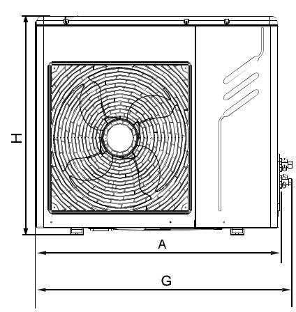
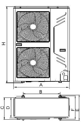
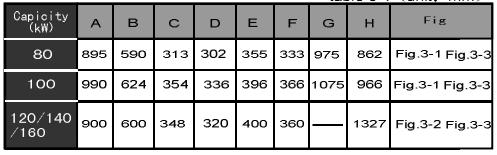
16 2. Dimensions 18 Outdoor Units
17 > Service Space Single unit installation (Wall or obstacle) Air inlet >300 Air inlet >300 >600 Maintain channel Air outlet Parallel connect the two units or above >300 >600 >2000 Parallel connect the front with rear sides >2000 >500 >3000 >3000 >300
18 4. Piping Diagrams High pressure switch Electronic expansion valve Evaporator Electronic expansion valve Oil separator Condenser High pressure liquid accumulator can Compressor Oil return Capillary Low pressure switch Low pressure liquid accumulator can 20 Outdoor Units

19 5. Wiring Diagrams Single phase
20 Three phase 22 Outdoor Units
21 6. Field Wiring Single phase L N P Q E Outdoor Unit 2 3x4.0mm 3-Shielded wise 2 (3x0.5mm ) Power Supply Power Supply To CCM wire distribution box To other indoor unit 2 3x1.0mm L N P Q E X Y E L N P Q E X Y E Indoor Unit Indoor Unit Indoor Unit Power ( V~ 50Hz) 1 Phase Switch / Circuit breaker Power wiring (outdoor) Power ( V~ 50Hz) 1-Phase Switch / Circuit breaker Power wiring (indoor) wire distribution box in broken line table, users can purchase the Central control montior when necessary. Outdoor Unit Communication Bus Indoor Unit Indoor Unit Indoor Unit Central control monitor (CCM) Computer Single phase indoor unit WHITE BLUE BLACK YELLOW GRAY BLACK Display board L N X Y E P Q E Y/G XT1 XT3 Wire controller Indoor Unit Power V~50Hz To Central Control Monitor (CCM) COMM. BUS To Outdoor COMM.BUS Please use 3-core shielded wire, and connect the shielded layer to Grounding To wire controller The reserved wire control function is indicated in broken line table, users can purchase the wire controller when necessary.
22 Three phase L1 L2 L3 N X Y E P Q E Outdoor unit X Y E CCM CCM 5x2.5mm Power Supply X Y E Signal wire between indoor/outdoor unit Indoor unit Indoor unit Indoor unit L N P Q E X Y E L N P Q E X Y E L N P Q E X Y E 3x1.0mm Power Supply Branch Box Branch Box Branch Box Signal wire between indoor units Please use 3-core shielded wire, and connect the shielded layer to Grounding Power ( V~ 50Hz) 3 Phase Power ( V~ 50Hz) 1-Phase Switch / Circuit breaker Power wiring (outdoor) Switch / Circuit breaker Power wiring (indoor) wire distribution box Outdoor Unit CCM Indoor Unit Indoor Unit Indoor Unit Communication Bus in broken line table, users can purchase the Central control montior when necessary.please contract with local supplier in details. Central control monitor (CCM) Computer Single phase indoor unit WHITE BLUE BLACK YELLOW GRAY BLACK Display board L N X Y E P Q E Y/G XT1 XT3 Wire controller Indoor Unit Power V~50Hz To Central Control Monitor (CCM) COMM. BUS To Outdoor COMM.BUS Please use 3-core shielded wire, and connect the shielded layer to Grounding To wire controller The reserved wire control function is indicated in broken line table, users can purchase the wire controller when necessary. 24 Outdoor Units
23 7. Capacity Tables 38VR003H Cooling Combinati on (%) (Capacity index) 130% 120% 110% Outdoor Air temperatu re( C DB) Indoor temperature( C WB) TC PI TC PI TC PI TC PI TC PI TC PI TC PI kw kw kw kw kw kw kw kw kw kw kw kw kw kw
24 100% 90% 80% % Outdoor Units
25 60% 50% Note: 1, is shown as reference 2, In cooling mode, avoid the outdoor air temperature range from degree C, when selecting the models 3, The above table shows the average value of conditions may operate 4, It is recommended to connect less than 130%
26 Heating Combinati on (%) (Capacity index) % 120% 110% 100% Outdoor Air temperature( C DB) Indoor temperature( C WB) TC PI TC PI TC PI TC PI TC PI TC PI kw kw kw kw kw kw kw kw kw kw kw kw C DB C WB Outdoor Units
27 90% 80% 70%
28 60% 50% Note: 1, is shown as reference 2, In heating mode, avoid the outdoor air temperature range from -15 to -20 degree C, when selecting the models 3, The above table shows the average value of conditions may operate 4, It is recommended to connect less than 130% 30 Outdoor Units
29 38VR004H10201S Cooling Combinatio n (%) (Capacity index) 130% 120% 110% Outdoor Air temperature ( C DB) Indoor temperature( C WB) TC PI TC PI TC PI TC PI TC PI TC PI TC PI kw kw kw kw kw kw kw kw kw kw kw kw kw kw
30 100% 90% 80% 70% Outdoor Units
31 60% 50% Note: 1, is shown as reference 2, In cooling mode, avoid the outdoor air temperature range from degree C, when selecting the models 3, The above table shows the average value of conditions may operate 4, It is recommended to connect less than 130%
32 Heating Combinati on (%) (Capacity index) % 120% 110% 100% Outdoor Air temperature( C DB) Indoor temperature( C WB) TC PI TC PI TC PI TC PI TC PI TC PI kw kw kw kw kw kw kw kw kw kw kw kw C DB C WB Outdoor Units
33 90% 80% 70%
34 60% 50% Note: 1, is shown as reference 2, In heating mode, avoid the outdoor air temperature range from -15 to -20 degree C, when selecting the models 3, The above table shows the average value of conditions may operate 4, It is recommended to connect less than 130% 36 Outdoor Units
35 38VR004H Cooling Combinati on (%) (Capacity index) 130% 120% 110% Outdoor Indoor temperature( C WB) Air temperatu re( C TC PI TC PI TC PI TC PI TC PI TC PI TC PI DB) kw kw kw kw kw kw kw kw kw kw kw kw kw kw
36 100% 90% 80% 70% Outdoor Units
37 60% 50% Note: 1, is shown as reference 2, In cooling mode, avoid the outdoor air temperature range from degree C, when selecting the models 3, The above table shows the average value of conditions may operate 4, It is recommended to connect less than 130%
38 Heating Combinati on (%) (Capacity index) % 120% 110% 100% Outdoor Air temperature( C DB) Indoor temperature( C WB) TC PI TC PI TC PI TC PI TC PI TC PI kw kw kw kw kw kw kw kw kw kw kw kw C DB C WB Outdoor Units
39 90% 80% 70%
40 60% 50% Note: 1, is shown as reference 2, In heating mode, avoid the outdoor air temperature range from -15 to -20 degree C, when selecting the models 3, The above table shows the average value of conditions may operate 4, It is recommended to connect less than 130% 42 Outdoor Units
41 38VR005H Cooling Combinati on (%) (Capacity index) 130% 120% 110% 100% Outdoor Air temperatu re( C DB) Indoor temperature( C WB) TC PI TC PI TC PI TC PI TC PI TC PI TC PI kw kw kw kw kw kw kw kw kw kw kw kw kw kw
42 90% 80% 70% Outdoor Units
43 60% 50% Note: 1, is shown as reference 2, In cooling mode, avoid the outdoor air temperature range from degree C, when selecting the models 3, The above table shows the average value of conditions may operate 4, It is recommended to connect less than 130%
44 Heating 46 Combinatio n (%) (Capacity index) 130% 120% 110% 100% Outdoor Air temperature ( C DB) Indoor temperature( C WB) TC PI TC PI TC PI TC PI TC PI TC PI C DB C WB kw kw kw kw kw kw kw kw kw kw kw kw Outdoor Units
45 90% 80% 70%
46 60% 50% Note: 1, is shown as reference 2, In heating mode, avoid the outdoor air temperature range from -15 to -20 degree C, when selecting the models 3, The above table shows the average value of conditions may operate 4, It is recommended to connect less than 130% 48 Outdoor Units
47 38VR006H Cooling Combinati on (%) (Capacity index) 130% 120% 110% 100% Outdoor Air temperatu re( C DB) Indoor temperature( C WB) TC PI TC PI TC PI TC PI TC PI TC PI TC PI kw kw kw kw kw kw kw kw kw kw kw kw kw kw
48 90% 80% 70% Outdoor Units
49 60% 50% Note: 1, is shown as reference 2, In cooling mode, avoid the outdoor air temperature range from degree C, when selecting the models 3, The above table shows the average value of conditions may operate 4, It is recommended to connect less than 130%
50 Heating 52 Combinatio n (%) (Capacity index) 130% 120% 110% 100% Outdoor Air temperature ( C DB) Indoor temperature( C WB) TC PI TC PI TC PI TC PI TC PI TC PI C DB C WB kw kw kw kw kw kw kw kw kw kw kw kw Outdoor Units
51 90% 80% 70%
52 60% 50% Note: 1, is shown as reference 2, In heating mode, avoid the outdoor air temperature range from -15 to -20 degree C, when selecting the models 3, The above table shows the average value of conditions may operate 4, It is recommended to connect less than 130% 54 Outdoor Units
53 38VR004H Cooling Combi nation (%) (Capa city index) 130% 120% 110% Outdoor Air tempera ture( C DB) Indoor temperature( C WB) TC PI TC PI TC PI TC PI TC PI TC PI TC PI kw kw kw kw kw kw kw kw kw kw kw kw kw kw
54 100% 90% 80% 70% Outdoor Units
55 60% 50% Note: 1, is shown as reference 2, In cooling mode, avoid the outdoor air temperature range from degree C, when selecting the models 3, The above table shows the average value of conditions may operate 4, It is recommended to connect less than 130%.
56 Heating 58 Combinatio n (%) (Capacity index) 130% 120% 110% 100% Outdoor Air temperature ( C DB) Indoor temperature( C WB) TC PI TC PI TC PI TC PI TC PI TC PI C DB C WB kw kw kw kw kw kw kw kw kw kw kw kw Outdoor Units
57 % 80% 70%
58 % 50% Note: 1, is shown as reference 2, In heating mode, avoid the outdoor air temperature range from -15 to -20 degree C, when selecting the models 3, The above table shows the average value of conditions may operate 4, It is recommended to connect less than 130% 60 Outdoor Units
59 38VR005H Cooling Combi Outdoor Indoor temperature( C WB) nation Air (%) tempera TC PI TC PI TC PI TC PI TC PI TC PI TC PI (Capa ture( C city DB) kw kw kw kw kw kw kw kw kw kw kw kw kw kw % 120% 110% 100%
60 90% 80% 70% Outdoor Units
61 60% 50% Note: 1, is shown as reference 2, In cooling mode, avoid the outdoor air temperature range from degree C, when selecting the models 3, The above table shows the average value of conditions may operate 4, It is recommended to connect less than 130%
62 Heating 64 Combinatio n (%) (Capacity index) 130% 120% 110% 100% Outdoor Air temperature ( C DB) Indoor temperature( C WB) TC PI TC PI TC PI TC PI TC PI TC PI C DB C WB kw kw kw kw kw kw kw kw kw kw kw kw Outdoor Units
63 % 80% 70%
64 % 50% Note: 1, is shown as reference 2, In heating mode, avoid the outdoor air temperature range from -15 to -20 degree C, when selecting the models 3, The above table shows the average value of conditions may operate 4, It is recommended to connect less than 130% 66 Outdoor Units
65 38VR006H Cooling Combi Outdo Indoor temperature( C WB) nation or Air (%) tempe TC PI TC PI TC PI TC PI TC PI TC PI TC PI (Capa rature city ( C kw kw kw kw kw kw kw kw kw kw kw kw kw kw % 120% 110% 100%
66 90% 80% 70% Outdoor Units
67 60% 50% Note: 1, is shown as reference 2, In cooling mode, avoid the outdoor air temperature range from degree C, when selecting the models 3, The above table shows the average value of conditions may operate 4, It is recommended to connect less than 130%
68 Heating 70 Combinatio n (%) (Capacity index) 130% 120% 110% 100% Outdoor Air temperature ( C DB) Indoor temperature( C WB) TC PI TC PI TC PI TC PI TC PI TC PI C DB C WB kw kw kw kw kw kw kw kw kw kw kw kw Outdoor Units
69 % 80% 70%
70 % 50% Note: 1, is shown as reference 2, In heating mode, avoid the outdoor air temperature range from -15 to -20 degree C, when selecting the models 3, The above table shows the average value of conditions may operate 4, It is recommended to connect less than 130% 72 Outdoor Units
71 MCAC-HTSM Electric Characteristics Model Outdoor Unit Power Supply Compressor OFM Hz Voltage Min. Max. TOCA MFA RLA kw FLA 38VR003H V 198V 242V 30 30A VR004H10201S V 198V 242V 30 30A VR004H V 198V 242V 30 30A VR005H V 198V 242V 30 30A VR006H V 198V 242V 30 30A VR004H V~415V 342V 440V 15 25A 9.3 2*0.1 2*0.9 38VR005H V~415V 342V 440V 15 25A 9.3 2*0.1 2*0.9 38VR006H V~415V 342V 440V 15 25A *0.9 Remark: TOCA: Total Over-current Amps. (A) MFA: Max. Fuse Amps. (A) RLA: Rated Locked Amps. (A) OFM: Outdoor Fan Motor. FLA: Full Load Amps. (A) KW: Rated Motor Output (KW)
72 Summarize of Installation 9. Sound Levels Noise level db(a) Model High speed Low speed 38VR003H VR004H10201S VR004H VR005H VR006H VR004H VR005H VR006H Outdoor Units
73 10. Operation Limits Cooling Heating 45 DB) Outdoor temperature( Range for continuous operation DB) Outdoor temperature( Range for continuous operation Indoor temperature( WB) Indoor temperature( WB) Installation 71
74 Part 3 Installation 1. Summarize of Installation Outdoor Units Installation Installation of Refrigerant Pipe Processing & Installation of Drainage Pipe Insulation Work Electric Installation Test Running Precautions on Refrigerant Leakage Installation
75 1. Summarize of Installation 1.1 Installation Procedure Installation 73
76 1.2 Install indoor units Procedure: Confirm installation position Label installation position Install hooks Install indoor units Note: (1) The hook must strong enough to sustain the weight of indoor unit. (2) Check the models of indoor units before installation. (3) Pay attention to the main devices, such as the pipeline. (4) Hold enough places for maintenance. 1.3 Refrigerant pipe Procedure: Install indoor units Install pipe Weld Add Nitrogen Temporary pipeline Flush Pressure test Vacuum dry 1.4 Drainage pipe Procedure: Install indoor units Connect drainpipe Check water leakage Drainpipe heat-insulation and test-run Note: It is no need to insulate the drainpipe if you choose the plastic pipe as drainpipe. 1.5 Electric wiring (1) Please select power supply for indoor unit and outdoor unit separately. Both indoor units and outdoor units should be grounded well. (2) The power supply should have specified branch circuit with leakage protector and manual switch. (3) Please put the connective wiring system between indoor unit and outdoor unit with refrigerant piping system together. (4) Power wiring should be done by professional electrician and complied with relevant National Electric Standard. (5) The power supply, leakage protector and manual of all the indoor units connecting to the same outdoor unit should be universal. (Please set all the indoor unit power supply of one system into the same circuit.) (6) It is suggested to use 3-core shielded wire as signal wire between indoor and outdoor units, multi-core wire is unavailable. Pay attention to the consistency. When signal wire parallel to the power wire, please keep enough distance (about 300mm at least) to prevent interference. (7) The power wire and signal wire can t be enlaced together. 1.6 Lay the indoor pipeline Note: Collocate the air-outlet reasonably to prevent airflow short-circuit. Check the static pressure whether in the allowable range. The air filters should be easy to unpick and wash. Do pressure test on pipeline. 74 Installation
77 1.7 Heat-insulation Procedure: Refrigerant pipe work Check the heat-insulated part Pressure test Heat-insulation work Note: For welding part, flare part and branch pipe, heat-insulation work must be done after finished the pressure test. 1.8 Install outdoor unit Note: (1) Gutter must be set around the foundation to drain the condensation water. (2) When installing outdoor units at the roof, please check the strength of the roof and pay attention not to destroy the waterproof of the roof. 1.9 Recharge refrigerant Procedure: Calculate the added volume according to liquid pipe length Recharge refrigerant Note: Please calculate the additional amount of refrigerant according to the formula that we supply to you, and the calculation result must be correct 1.10 Main points of test running and debugging Please check the following issues before turning on the power: (1). Vacuum dry: Make sure the vacuum degree accord with our requirement about (2). Wiring: Includes the power wiring and communication wiring; Recheck the connection according to our corresponding wire diagrams. Especially, please remember our communication wire is polar; it means you must connect the communication wire correspondingly to the terminal block. (3). Additional charge of refrigerant: Recheck the calculation formula and recalculate the total recharge volume according to our supplied formula. (4). Open the stop-valve of gas and liquid pipe with Allen key; Check leakage of stop-valve with soap water. Please confirm whether the outdoor unit has been connected to the power for 12hr before start test running. Test running: Turn on all of the indoor units with cooling mode and set the temperature in 17degree with high fan speed first, after the system operated, test following operation parameters of the system, including indoor units and outdoor units parameters. Installation 75
78 > Outdoor Units Installation 2.1 Installation place Please keep away from the following place, or malfunction of the machine may be caused: There is combustible gas leakage. There is much oil (including engine oil) ingredient. There is salty air surrounding (near the coast) There is caustic gas (the sulfide, for example) existing in the air (near a hot spring) A place the heat air expelled out from the outdoor unit can reach your neighbor s window. A place that the noise interferes your neighbors everyday life A place that is too weak to bear the weight of the unit Uneven place. Insufficient ventilation place. Near a private power station or high Frequency equipment. Install indoor unit, outdoor unit, power cord and connecting wire at least 1m away from TV set or radio to prevent noise The insulation of the metal parts of the building and the air conditioner should comply with the regulation of National Electric Standard. CAUTION Keep indoor unit, outdoor unit, power supply wiring and transmission wiring at least 1 meter away from televisions and radios. This is to prevent image interference and noise in those electrical appliances. (Noise may be generated depending on the conditions under which the electric wave is generated, even if 1 meter is kept.) 2.2 Installation space Single unit installation (Wall or obstacle) Air inlet >300 Air inlet >300 >600 Maintain channel Air outlet Parallel connect the two units or above >300 >600 > Installation
79 >60cm Parallel connect the front with rear sides >2000 >500 >3000 >3000 > Moving and installation Since the gravity center of the unit is not at its physical center, so please be careful when lifting it with a sling. Never hold the inlet of the outdoor unit to prevent it from deforming. Do not touch the fan with hands or other objects. Do not lean it more than 45, and do not lay it sidelong. Make concrete foundation according to the specifications of the outdoor units.(refer to below Fig) Fasten the feet of this unit with bolts firmly to prevent it from collapsing in case of earthquake or strong wind. (refer to below Fig) mm Fix with bolt NOTE All the pictures in this manual are for explanation purpose only. They may be slightly different from the air conditioner you purchased (depend on model).the actual shape shall Prevail. Installation 77
80 3. Installation of Refrigerant Pipe CAUTION To prevent the refrigerant piping from oxidizing inside when welding, it is necessary to charge nitrogen, or oxide will chock the circulation system. 3.1 Using Branch pipe Length and Drop Height Permitted of the Refrigerant piping Outdoor unit Drop Height between Indoor unit and outdoor Unit L The first Line Branch Pipe 1 L 3 L 2 Maximum Piping Equivalent Length (From the first Line branch pipe) Maximum piping Equivalent Length L 4 L5 L6 A B C D E Indoor Unit to Indoor Unit Drop Height Indoor Unit Total Pipe Length (Actual) Permitted value 100m Piping L1+L2+L3+L4+L5+L6 +A+B+C+D+E Pipe Length Maximum Piping(L) Actual Length Equivalent Length 45m(8Kw/10Kw) 60m(12/14/16Kw) 50m(8Kw/10Kw) 70m(12/14/16Kw) L1+L3+L4+L5+L6+ E Pipe length (from the first line branch to farthest indoor unit) 20m L3+L4+L5+L6+E Drop Height Indoor Unit outdoor unit Outdoor Unit Up 30m / 78 Installation
81 Drop Height Outdoor Unit Down 20m / Indoor Unit to Indoor Unit Drop Height 8m / Note: Conversion of the equivalent length: Convert into the direct pipe length according to branch Junction 0.5m/l Pipe size selection Selection of the refrigerant pipe Type of the pipe Connecting part No. Main pipe Between outdoor branch joint and first branch joint 1 Indoor main pipe Between indoor branch joint 2 Indoor pipe Between branch part and indoor unit How to choose the Branch part and the refrigerant pipe? According the total capacity of outdoor units to select the dimension of main pipe 1: Refrigerant R410A Remarks Capacity of outdoor unit (kw) Gas side Liquid side 8 Φ15.9 Φ Φ15.9 Φ Φ15.9 Φ Φ15.9 Φ Φ19.1 Φ9.52 A converter pipe is needed for the connection between first branch joint and outdoor unit. Notes: Branch header must be connected with indoor units directly, the further branch connection is not allowed The maximum connection of indoor units: Capacity of Capacity of outdoor unit (kw) Outdoor unit (horsepower) Maximum Quantity of Indoor unit Sum capacity of indoor unit (kw) %~130% %~130% %~130% %~130% %~130% According the capacity of indoor units to select indoor main pipe 2, main pipe 3 and branch joint: A: the total capacity and the gas side/liquid side pipe of indoor units Installation 79

82 Installation Modification main pipe 1: According to the and step of calculation result, If the main pipe dimension according to outdoor capacity selection result are different from indoor capacity selection result, so the main pipe dimension you should selection bigger pipe Connecting method Gas side Liquid side 4, 5,6 HP Outdoor unit Flaring nut Flaring nut The dimension of branch part Branch list Name Gas side joint Liquid Side Joints BJF-224-CM BJF-330-CM 3.2 Using four divergence box Length and Drop Height Permitted of the Refrigerant piping I D : ( I D : ) O D : I D : O D : I D : I D : I D : ( I D : ) O D : O D : I D : 9. 5 I D : 9. 5 I D : 6. 4 O D : 9. 5 I D : 6. 4 O D : 9. 5 I D : 9. 5 I D : ( I D : ) O D : I D : O D : I D : I D : I D : ( I D : ) O D : I D : O D : I D : 6. 4 I D : 9. 5 O D : O D : I D : I D : 9. 5 I D : I D : 6. 4 I D : 9. 5
Contents. Introduction Part 1 General Information Part 2 General Instruction Part 3 Outdoor Units Part 4 Installation...
 MHVAC-DTSM-2012-07 Contents Contents Introduction... 1 Part 1 General Information... 2 Part 2 General Instruction... 13 Part 3 Outdoor Units... 17 Part 4 Installation... 316 Part 5 Control System... 356
VRF. Technical Data Book. DVM S ECO for Europe (R410A, 50Hz, HP) Model : AM***KXMDGH/EU
 Model : AM***KXMDGH/EU") VRF Technical Data Book DVM S ECO for Europe (R410A, Hz, HP) Model : AM***KXMDGH/EU History Version Modification Date Remark 1 Newly Release the TDB 15.12.15 Nomenclature Outdoor Units Model Names AM 080
VRF Technical Data Book DVM S ECO for Europe (R410A, Hz, HP) Model : AM***KXMDGH/EU History Version Modification Date Remark 1 Newly Release the TDB 15.12.15 Nomenclature Outdoor Units Model Names AM 080
System Soft-optimization Tests of Refrigerant R-32 in a 6-ton Rooftop Packaged Air-Conditioner
 System Soft-optimization Tests of Refrigerant R-32 in a 6-ton Rooftop Packaged Air-Conditioner Mohammad Khawaldeh Director, Unitary & Applied Product Units Presentation Outline Objectives Challenges Base
MAINLINE MLA14 AIR CONDITIONERS
 FORM NO. AML-220 Supersedes Form No. PTZ-789 MAINLINE AIR CONDITIONERS Efficiencies up to 16 /13 Nominal Sizes 1.5-5 Ton [5.28 TO 17.6 KW] Cooling Capacities 17.3 to 60.5 kbtu [5.7 to 17.7 kw] Manufactured
Research of Variable Volume and Gas Injection DC Inverter Air Conditioning Compressor
 Purdue University Purdue e-pubs International Compressor Engineering Conference School of Mechanical Engineering 2016 Research of Variable Volume and Gas Inection DC Inverter Air Conditioning Compressor
The CWE / HWE-R Series: Overview. Frame and cabinet covering
 Table Of Contents The CWE / HWE-R Series: Overview...... 1 Frame and cabinet covering... 1 Refrigerant gas...... 2 Compressors...... 2 Condensers...... 2 Fans... 3 Evaporator...... 3 Refrigerant circuit......
Ducted Reverse Cycle Air Conditioning of Distinction
 Ducted Reverse Cycle Air Conditioning of Distinction Transforming global energy-efficiency into an art form! The Braemar advantage Braemar ducted reverse cycle air conditioners are brought to you by Seeley
Application of CHE100 in Frequency Conversion Alteration of Air Compressor System
 Application of CHE100 in Frequency Conversion Alteration of Air Compressor System Abstract: This paper describes application of CHE100 in frequency conversion alteration of the air compressor system and
AIR CONDITIONERS WA14**W SERIES
 FORM NO. A66-225 REV. 3 AIR CONDITIONERS Features Outdoor air conditioner designed for ground level or rooftop installations. These units offer comfort and dependability for single, multi-family and light
AIR CONDITIONERS WA14 SERIES
 FORM NO. A66-220 REV. 3 AIR CONDITIONERS Features Outdoor air conditioner designed for ground level or rooftop installations. These units offer comfort and dependability for single, multi-family and light
GRUNDFOS DATA BOOKLET. Hydro Solo-E. Complete pressure boosting systems 50/60 Hz
 GRUNDFOS DATA BOOKLET Complete pressure boosting systems 5/6 z Contents Product data Performance range 3 Operating conditions Inlet pressure Type key Product range 5 Construction 5 Installation 5 Mechanical
4HP15 PRODUCT SPECIFICATIONS 15 SEER SPLIT SYSTEM HEAT PUMP
 4HP15 PRODUCT SPECIFICATIONS 15 SPLIT SYSTEM HEAT PUMP FORM NO. 4HP15-100 (12/2017) FEATURES AND BENEFITS R410A Refrigerant High-quality condenser coil with copper tubing and enhanced louvered fin for
AIR CONDITIONERS. Features. Manufactured for Fujitsu General America, Inc. Fairfield, NJ. FORM NO. AFJ-220 Supersedes Form No.
 FORM NO. AFJ-220 Supersedes Form No. PTZ-789 AIR CONDITIONERS FO*14C SERIES Efficiencies up to 16 S/13 Nominal Sizes 1 1 /2 to 5 Ton [5.28 to 17.6 kw] Cooling Capacities 17.3 to 60.5 kbtu [5.7 to 17.7
Heat pumps for swimming pools
 Heat pumps for swimming pools Full range of heat pumps for indoor and outdoor swimming i pools The best heating for your pool Reliable and effective Made in Europe www.calorex.com THE CHALLENGE: To provide
AIR CONDITIONERS. Features. Manufactured for Fujitsu General America, Inc. Fairfield, NJ. FORM NO. AFJ-222 Supersedes Form No.
 FORM NO. AFJ-222 Supersedes Form No. PTZ-789 AIR CONDITIONERS FO*16C SERIES Efficiencies up to 16 SEER/13 EER Nominal Sizes 1 1 /2 to 5 Ton [5.28 to 17.6 kw] Cooling Capacities 17.3 to 60.5 kbtu [5.7 to
SF SERIES CNG COMPRESSOR MODEL HF-4MH. 4 Nm3/Hour Displacement OPERATION MANUAL
 SF SERIES CNG COMPRESSOR MODEL HF-4MH 4 Nm3/Hour Displacement OPERATION MANUAL 1 Content 1. General Description...3 2. Main technical parameters...3 3. Structural principle...4 3.1Main structure...4 3.2Compressor
SRL Series. Oil-less Scroll Air Compressors. Pharmaceutical. Research & Development. Food & Beverage. Chemical. Electronic
 Pharmaceutical SRL Series Oil-less Scroll Air Compressors Research & Development Food & Beverage Chemical Electronic Hitachi Industrial Equipment Product Brochure Hitachi SRL Series scroll compressors
Evaporator (DX) Freon Applications 1 12 Tons MHF
 Freon Applications 1 12 Tons MHF") Evaporator (DX) Freon Applications 1 12 Tons > > Used For small to medium freon applications The Global Leader In Heat Exchange Technology With seven decades of experience and commitment to total client
Evaporator (DX) Freon Applications 1 12 Tons > > Used For small to medium freon applications The Global Leader In Heat Exchange Technology With seven decades of experience and commitment to total client
TECHNICAL MANUAL HEAVY DUTY HORIZONTAL MICRO-COMPRESSOR Reference: RCMPH
 TECHNICAL MANUAL HEAVY DUTY HORIZONTAL MICRO-COMPRESSOR Reference: RCMPH THIS MANUAL IS INTENDED FOR TECHNICAL STAFF IN CHARGE OF THE INSTALLATION, THE OPERATION AND THE MAINTENANCE OF THIS PRODUCT CAUTION!
AIR CONDITIONERS. Features. Manufactured for Fujitsu General America, Inc. Fairfield, NJ. FORM NO. AFJ-221 Supersedes Form No.
 FORM NO. AFJ-221 Supersedes Form No. PTZ-789 AIR CONDITIONERS FO*13C SERIES Efficiencies 13-15.5 SEER/11.5-13 EER Nominal Sizes 1 1 /2 to 5 Ton [5.28 to 17.6 kw] Cooling Capacities 17.3 to 60.5 kbtu [5.7
Earlier Lecture. In the earlier lecture, we have seen Kapitza & Heylandt systems which are the modifications of the Claude System.
 17 1 Earlier Lecture In the earlier lecture, we have seen Kapitza & Heylandt systems which are the modifications of the Claude System. Collins system is an extension of the Claude system to reach lower
NLE10CN V/50Hz 1~
 nle10cn_105h6175_r290_2v_50hz_06-18_ds.xlsx Sales code: 105H6175 NLE10CN 2-240V/50Hz 1~ design Oil type Polyolester Refrigerant(s) R290 Oil viscosity 32cSt Displacement 10,09cm³ / 0,62cu.in Oil quantity
CNG FILLING STATIONS
 CNG FILLING STATIONS GAS INLET 3/4 F EXIT CNG TO CAR TANK 5 mt / 16 feet HOSE AND FILLING NOZZLE REMOTE ELECTRIC PANEL THREE-PHASE height 40 cm / 15.7 width 30 cm / 11.8 depth 20 cm / 7.8 EQUIPPED WITH
DLE7.5CN V/50Hz 1~
 dle75cn_102h4856_r290_2v_50hz_06-18_ds.xlsx Sales code: 102H4856 DLE7.5CN 2-240V/50Hz 1~ design Oil type Polyolester Refrigerant(s) R290 Oil viscosity 32cSt Displacement 7,48cm³ / 0,46cu.in Oil quantity
DLE5.7CN V/60Hz 1~
 dle57cn_102h3682_r290_115v_60hz_06-18_ds.xlsx Sales code: 102H3682 1~ design Oil type Polyolester Refrigerant(s) R290 Oil viscosity 32cSt Displacement 5,7cm³ / 0,35cu.in Oil quantity 221cm³ / 7,5fl.oz
Gas Vapor Injection on Refrigerant Cycle Using Piston Technology
 Purdue University Purdue e-pubs International Refrigeration and Air Conditioning Conference School of Mechanical Engineering 2012 Gas Vapor Injection on Refrigerant Cycle Using Piston Technology Sophie
DLE6.5CN V/60Hz 1~
 dle65cn_102h3792_r290_115v_60hz_06-18_ds.xlsx Sales code: 102H3792 1~ design Oil type Polyolester Refrigerant(s) R290 Oil viscosity 32cSt Displacement 6,5cm³ / 0,4cu.in Oil quantity 221cm³ / 7,5fl.oz s
Compresor lg de BTU modelo QP325KCB
 Compresor lg de 24000 BTU modelo QP325KCB Compresor lg de 24000 BTU modelo QP325KCB Ref. No. LGETA-140115-1576 Issued Date 2014.01.15 0.Revision History Rev. No. Rev. 0 Rev. Date - Data Rev. No Rev. description
Guideline No.M-05(201510) M-05 AIR COMPRESSOR. Issued date: 20 October China Classification Society
 M-05 AIR COMPRESSOR. Issued date: 20 October China Classification Society") Guideline No.M-05(201510) M-05 AIR COMPRESSOR Issued date: 20 October 2015 China Classification Society Foreword This Guideline constitutes the CCS rules, and establishes the applicable technical requirements
Guideline No.M-05(201510) M-05 AIR COMPRESSOR Issued date: 20 October 2015 China Classification Society Foreword This Guideline constitutes the CCS rules, and establishes the applicable technical requirements
Uniflair LE TDAR-TUAR
 Uniflair LE TDAR-TUAR Direct Expansion air-cooled units with backward-curved fans 20-100kW > Perimeter cooling for medium/large data center > Refrigerant R-410A Available Versions: > Downflow (TDAR) >
NAUTILUS Small pump. Powerful performance. Certified according to DIN 14425, submersible pumps for fire departments
 NAUTILUS Small pump. Powerful performance. Certified according to DIN 14425, submersible pumps for fire departments The first choice for high water and flooding. Rosenbauer NAUTILUS submersible pump NAUTILUS.
PLEASE READ CAREFULLY BEFORE INSTALLING OR USING MEGA POOL SAVER MPS 1100
 MPS-1100 User Manual Mega Pool Saver Ltd PLEASE READ CAREFULLY BEFORE INSTALLING OR USING MEGA POOL SAVER MPS 1100 For further up to date instructions on how to install Mega Pool Saver MPS 1100, please
New Energy-saving Air Compressors
 FEATURED ARTICLES Environmentally Conscious Technology in Industrial Fields Aiming for a Low-carbon Society New Energy-saving Air Compressors Air compressors produce compressed air and have a wide variety
market leading commercial and domestic ventilation with heat recovery Nilan VPM Active heat recovery and cooling (air/air)
") market leading commercial and domestic ventilation with heat recovery Nilan VPM 120-560 Active heat recovery and cooling (air/air) Nilan VPM 120-560 Industrial ventilation with heat recovery and cooling
market leading commercial and domestic ventilation with heat recovery Nilan VPM 120-560 Active heat recovery and cooling (air/air) Nilan VPM 120-560 Industrial ventilation with heat recovery and cooling
Screw Compressors 11-22kW
 INDUSTRIALS GROUP Screw Compressors 11-22kW KSA Plus Fixed Speed, KSV Variable Speed Smart and affordable CHAMPION COMPRESSED AIR TECHNOLOGIES KSA Plus Screw Compressors Up to 45 C ambient temperature
Product Range. High performance and economic high pressure solutions Made in Germany
 Product Range Purification Storage Filling Panels Nitrox/Trimix High performance and economic high pressure solutions Made in Germany www.lw-compressors.com 2 Lenhardt & Wagner Solid Growth Lenhardt &
NLE11CNL V/60Hz 1~
 nle11cnl_105h5981_r290_115v_60hz_11-18_ds.xlsx Sales code: 105H5981 NLE11CNL 115-7V/60Hz 1~ design Oil type Polyolester Refrigerant(s) R290 Oil viscosity 32cSt Displacement 11,15cm³ / 0,68cu.in Oil quantity
Electric regulating valves Type CCMT 2 - CCMT 8 / CCMT 16 - CCMT 42
 Data sheet Electric regulating valves Type CCMT 2 - CCMT 8 / CCMT 16 - CCMT 42 The CCMT is an electrically operated valve designed specifically for operation in CO 2 systems. The CCMT valve concept is
SSR. Smart Valve Positioner.
 Smart Valve Positioner Smartest valve control device meeting a dynamic performance and a precise setting with a piezoelectric technology and an optimized auto-calibration program Features Auto-Calibration
Multiple Pressure Booster Systems With Variable Speed Controller Type BL
 Multiple Pressure Booster Systems With Variable Speed Controller Type BL General Characteristics - Single or multistage pumps - Horizontal or vertical mounting - Total head 30m ~ 250m - Material construction:
SSL. Smart Valve Positioner.
 Smart Valve Positioner Smartest valve control device meeting a dynamic performance and a precise setting with a piezoelectric technology and an optimized auto-calibration program Features Auto-Calibration
FMU4X, FMC4X FMU4P, FMC4P
 ENVIRONMENTALLY SOUND REFRIGERANT FMU4X, FMC4X FMU4P, FMC4P Product Specifications HORIZONTAL FAN COILS FMU4P and FMC4P 1 1/2, 2, 2 1/2, and 3 Tons FMU4X and FMC4X 1 1/2, 2 and 2 1/2 Tons ALL MODELS Horizontal
SonoMeter 30 Energy Meters
 Data Sheet SonoMeter 30 Energy Meters Description The Danfoss SonoMeter 30 is a range of ultrasonic, compact energy meters intended for measuring energy consumption in heating and cooling applications
Vortex Flow Meter Wafer or Flange Connection. - Steam - Liquid - Gas
 Vortex Flow Meter Wafer or Flange Connection - Steam - Liquid - Gas Working Principle & Circuit Diagram Working Principle When a column body placed in flowing fluids in pipe, a series of vortices will
RP series Rotor Pumps
 ontact etails RP series Rotor Pumps Nomenclature Features Low noise Substantial reduction of the operation noise, by to db (comparison with aikin products), and improved sound quality are achieved by adopting
TECHNICAL DESCRIPTION
 TECHNICAL DESCRIPTION Exhaust Hose Reel ser. 865, electric motor driven No. 981118101 Description Limit switches, for hose coiling and uncoiling integrated in drive unit. Motor turns drum via a planetary
Semi-Hermetic compact screw compressors
 CX Series Frascold CX compact screw compressors range has been designed to grant the maximum efficiency, reliability and flexibility. Currently the range consists of 566 models, which cover not only a
CO 2 radial piston compressor (transcritical)
") CO 2 radial piston compressor (transcritical) At a glance Operating limits and performance data Technical data Dimensions and connections Scope of supply 124 126 129 130 131 Radial piston compressor (transcritical)
CO 2 radial piston compressor (transcritical) At a glance Operating limits and performance data Technical data Dimensions and connections Scope of supply 124 126 129 130 131 Radial piston compressor (transcritical)
/ /
 GN 4- kw/5.5-0 hp Dual Output Compressors (Air/Nitrogen) Driving Nitrogen Forward GN: the dual output solution From cargo blanketing in LNG vessels to the inflation of Formula tires, nitrogen is used in
ASM. Asynchronous Spindle Motors. SEM Limited Faraday Way Orpington, Kent BR5 3QT United Kingdom
 NE ASM Asynchronous Spindle Motors SEM Limited Faraday Way Orpington, Kent BR 3QT United Kingdom Tel: +44 ()189 8847 Fax: +44 ()189 884884 Email: sales@sem.co.uk Web: www.sem.co.uk Version 4 August 2 Asynchronous
TABLE OF CONTENTS 2 TALAS DRYER 4 TALAS MEASURER 7 TALAS PORTABLE DRYER 9 TALAS LEAKER 11 TALAS STARTER 14 TALAS AUXILIARY 17 APPENDICES
 TABLE OF CONTENTS 2 TALAS DRYER 4 TALAS MEASURER 7 TALAS PORTABLE DRYER 9 TALAS LEAKER 11 TALAS STARTER 14 TALAS AUXILIARY 17 APPENDICES ALL PICTURES SHOWN ARE FOR REFERENCE ONLY ACTUAL PRODUCT MAY VARY
Customer Responsibilities
 Thank you for purchasing an Agilent instrument. To get you started and to assure a successful and timely installation, please refer to this specification or set of requirements. Correct site preparation
KCS-Line. Air Cooled Condensers NEW CONTENTS PRODUCT DATA & INSTALLATION. Refrigerant: R404A, R507, R22
 PRODUCT DATA & INSTALLATION Bulletin K50-KCS-PDI-1 1085695 For 50Hz see Bulletin K50-KCS-PDI-50 We are on the Internet www.keepriterefrigeration.com KCS-Line Air Cooled Condensers Refrigerant: R404A, R507,
AE R8 December 2004 Reformatted November Copelametic Two-Stage Compressors Application and Service Instructions
 AE19-1132 R8 December 2004 Reformatted November 2010 Copelametic Two-Stage Compressors Application and Service Instructions The Copeland two stage compressors have been developed to efficiently achieve
Customer Responsibilities
 Thank you for purchasing an Agilent instrument. To get you started and to assure a successful and timely installation, please refer to this specification or set of requirements. Correct site preparation
Crankcase pressure regulator, type KVL REFRIGERATION AND AIR CONDITIONING. Technical leaflet
 Crankcase pressure regulator, type KVL REFRIGERATION AND AIR CONDITIONING Technical leaflet Contents Page Introduction.......................................................................................
Components for air preparation and pressure adjustment. OUT port position ( ) connected Rear side. of IN port. Air tank. directly.
 connected Rear side. of IN port. Air tank. directly.") Components preparation and pressure adjustment ABP Overview ABP is a component that enables boosting by s only up to twice primary pressure (.0MPa max.) in combination with using air tank but not using
Components preparation and pressure adjustment ABP Overview ABP is a component that enables boosting by s only up to twice primary pressure (.0MPa max.) in combination with using air tank but not using
Visualize Nitrogen Gas Consumption
 Air Flow Monitor EWA2 SERIES Conforming to EMC Directive (all models) & Pressure Equipment Directive (AEWA2150/2200 only) Visualize Nitrogen Gas Consumption Small pipe size as Well as Air Consumption!
4SCU16LS PRODUCT SPECIFICATIONS 16 SEER SPLIT SYSTEM ENHANCED AIR CONDITIONING DESIGN COMPONENTS WARRANTY COMPRESSOR CABINET COILS
 PRODUCT SPECIFICATIONS 16 S SPLIT SYSTEM ENHANCED AIR CONDITIONING FORM NO. -100 (06/2014) DESIGN Designed for ambients up to 125 F COMPONENTS Service valves positioned for quick installation and easy
ASERCOM guidelines for the design of multiple compressor racks using frequency inverters
 ASERCOM guidelines for the design of multiple compressor racks using frequency inverters Contents 1 SCOPE AND PURPOSE 2 SELECTION OF COMPRESSORS 3 DESIGN FEATURES 4 CONTROL FEATURES 5 STABILITY OF WORKING
Nordic Model CCM0330, 0430, 0530, 0630 Service Parts Manual (Includes 50Hz. Units)
") IMI CORNELIUS INC. www.cornelius.com Nordic Model CCM0330, 0430, 0530, 0630 Service Parts Manual (Includes 50Hz. Units) Publication Number: 631806058 Revision Date: October 13, 2009 Revision: E Visit the
IMI CORNELIUS INC. www.cornelius.com Nordic Model CCM0330, 0430, 0530, 0630 Service Parts Manual (Includes 50Hz. Units) Publication Number: 631806058 Revision Date: October 13, 2009 Revision: E Visit the
Technical Instructions Document No. CA2N4721E-P25 Rev. 1, February, Modulating Control Valve for Hot Gas Control.
 Document No. CAN7E-P MFB LX Series Modulating Control Valve Description Valves with magnetic actuator for modulating capacity control of refrigeration units and for heat recovery. Features Quick positioning
Self-priming makes priming unnecessary Exhausts the air inside the suction pipe to suck up liquid. Air operated type.
 Process Pump Series 3/5 Automatically Operated Type (Internal Switching Type)/Air Operated Type (External Switching Type) High abrasion resistance and low particle generation o sliding parts in wetted
MAINLINE MLP14**A HEAT PUMPS
 FORM NO. PML-806 REV. 2 Supersedes Form No. PTZ-789 MAINLINE HEAT PUMPS Efficiencies: 15 SEER/12.5 EER 9 HSPF Nominal Sizes 1 1 /2 to 5 Ton [5.28 to 17.6 kw] Cooling Capacities 17.3 to 60.5 kbtu [5.7 to
SERVICE PARTS MANUAL ICE SERIES CUBERS MODEL - ICE0250A5-T5-W5, ICE0400A4-T4-W4 MODEL - ICE0500A4-T4-W4-R5, ICE0606A4-T4-W4-R5 Includes 50Hz.
 SERVICE PARTS MANUAL ICE SERIES CUBERS MODEL - ICE0250A5-T5-W5, ICE0400A4-T4-W4 MODEL - ICE0500A4-T4-W4-R5, ICE0606A4-T4-W4-R5 Includes 50Hz. Units Date 1/09 Table Of Contents This parts list contains
Plant Air Energy Saving
 Compressor power Figures show reliable effects. Company A performance Electricity CO2 Cost 1400 kw We help you save energy. We help you to improve and standardize your equipment, and adopt new equipment.
better measurement Simply a question of SCHMIDT Flow Sensor SS The cost-effective alternative in pressurised systems up to 10 bars.
 Simply a question of better measurement SCHMIDT Flow Sensor SS 20.261 The cost-effective alternative in pressurised systems up to 10 bars. Compressed air technology Industrial processes A cost analysis
Simple Set. Pressure Independent Control Valves 2 Way 1/2-2
 The Bray Simple Set is a threaded pressure independent control (PIC) valve designed for a wide variety of hot water and chilled water control applications. The SS Series combines high rangeability control
ELITE Series R-410A. SEER up to to 5 Tons Cooling Capacity - 17,800 to 60,000 Btuh AIR CONDITIONERS EL16XC1 PRODUCT SPECIFICATIONS
 PRODUCT SPECIFICATIONS AIR CONDITIONERS EL16XC1 ELITE Series R-410A Bulletin 210758 November 2017 Supersedes August 2017 SEER up to 17.90 1.5 to 5 Tons Cooling Capacity - 17,800 to 60,000 Btuh MODEL NUMBER
Electric expansion valves Types AKV 10, AKV 15 and AKV 20
 Data sheet Electric expansion valves Types AKV 10, AKV 15 and AKV 20 AKV are electrically operated expansion valves designed for refrigerating plants. The AKV valves are normally controlled by a controller
KIT. Small Automatic Water Boosters KIT MODELS
 KIT Small Automatic Water Boosters The electronic controller KIT orders the automatic start and stop of the water pump when opening or closing any tap or valve in the installation. There are four main
DIAPHRAGM PUMPS WITH KNF STABILIZATION SYSTEM
 DIAPHRAGM PUMPS WITH KNF STABILIZATION SYSTEM DATA SHEET E 037 N 940.5 APE as AC version in IP 54 N 940.5 APE-W with multi-voltage power supply input (As an option adjustable with potentiometer or by external
Development of Large Capacity CO2 Scroll Compressor
 Purdue University Purdue e-pubs International Compressor Engineering Conference School of Mechanical Engineering 2008 Development of Large Capacity CO2 Scroll Compressor Kenji Yano Mitsubishi Electric
Customer Responsibilities. Important Customer Information. Cary 4000/5000/6000i UV-Vis spectrophotometer Site Preparation Checklist
 Thank you for purchasing an Agilent instrument. To get you started and to assure a successful and timely installation, please refer to this specification or set of requirements. Correct site preparation
AE R1 February 2015
 February 2015 CoreSense Diagnostics for Copeland Scroll UltraTech Air Conditioning Compressors TABLE OF CONTENTS Safety Safety Instructions... 2 Safety Icon Explanation... 2 Instructions Pertaining to
Product Range. Compressors Purification Storage Filling Panels Nitrox/Trimix. High Pressure Solutions from L&W!
 Product Range Purification Storage Filling Panels Nitrox/Trimix High Pressure Solutions from L&W! 2 Lenhardt & Wagner Solid Growth Lenhardt & Wagner is one of the leading and renowed companies in the market
AIR-SAVER G1 AIR-SAVER G2 LOCATOR-EV COMPRESSED AIR CONDENSATE MANAGEMENT AND ENERGY SAVING PRODUCTS AIR SAVING PRODUCTS
 AIR-SAVER G1 AIR-SAVER G2 LOCATOR-EV ENVIRONMENT ADDING VALUE SAFEGUARD RELIABLE COMPRESSED AIR CONDENSATE MANAGEMENT AND ENERGY SAVING PRODUCTS AIR SAVING PRODUCTS Air saving products INDEX Chapter Content
Product Data CAPVP, CARVP, CAPVU, CARVU EVAPORATOR COIL A COIL - CASED AND UNCASED UPFLOW, DOWNFLOW DESIGN FEATURES
 CAPVP, CARVP, CAPVU, CARVU EVAPORATOR COIL A COIL - CASED AND UNCASED UPFLOW, DOWNFLOW Product Data CAPVP / CARVP A06001 A06002 CAPVU / CARVU The CAPVP, CARVP, CAPVU, and CARVU evaporator coils incorporate
OFFER / ANGEBOT / DRAFT Media Supply Module >MSM6-380< HYDRAULICS/PNEUMATICS. > Compressor unit incl. filling station to supply the modules
 OFFER / ANGEBOT / DRAFT Media Supply Module HYDRAULICS/PNEUMATICS Example of a module For the use in the test range (QA) at the fitting installation in the final assembly line of the A380 Various modules
Soft-optimization test of R-410A alternative refrigerant R-32 in a split condensing unit - Phase II
 Soft-optimization test of R-410A alternative refrigerant R-32 in a split condensing unit - Phase II Stephen Li Daikin / Goodman Manufacturing Jan. 2016 1 2 Test objectives See the impact of R-32 on air
Quiz #1 Thermodynamics Spring, 2018 Closed Book, Open Appendices, Closed Notes, CLOSED CALCULATORS
 Quiz #1 Closed Book, Open Appendices, Closed Notes, CLOSED CALCULATORS An astronaut has a mass of 161 lbm on the surface of the earth. Calculate his weight (in lbf) on planet Rigel 4 where g = 20.0 ft/s
OPERATING INSTRUCTIONS
 OPERATING INSTRUCTIONS MODEL GS2000 / GS2001 OIL-LESS REFRIGERANT RECOVERY UNIT NATIONAL REFRIGERATION PRODUCTS 985 WHEELER WAY LANGHORNE, PA 19047 (215) 638-8909 FAX (215) 638-9270 R01099 GS2000.DOC NRP-OM-GS2000
MANUAL KPS Pressure Control Valve
 TetraTec Instruments GmbH Gewerbestrasse 8 71144 Steinenbronn Deutschland E-Mail: info@tetratec.de Tel.: 07157/5387-0 Fax: 07157/5387-10 MANUAL Pressure Control Valve *** VERSION 1.0 *** Update: 17.11.2006
Development of High Efficiency 4K Two-Stage Pulse Tube Cryocooler
 Development of High Efficiency 4K Two-Stage Pulse Tube Cryocooler M. Xu, H. Takayama and K. Nakano Sumitomo Heavy Industries, Ltd. Nishi-tokyo-city, Tokyo, Japan 188-8585 ABSTRACT Sumitomo Heavy Industries
6890 GC Site Preparation
 6890 GC Site Preparation (a16011) This document is believed to be accurate and up-to-date. However, Agilent Technologies, Inc. cannot assume responsibility for the use of this material. The information
Exercise 4-2. Centrifugal Pumps EXERCISE OBJECTIVE DISCUSSION OUTLINE DISCUSSION. Pumps
 Exercise 4-2 Centrifugal Pumps EXERCISE OBJECTIVE Familiarize yourself with the basics of liquid pumps, specifically with the basics of centrifugal pumps. DISCUSSION OUTLINE The Discussion of this exercise
Recirculating Coolers
 (Chillers) - Basic type Low Temp. - General Type Low Temp. - Intelligent type Selection Guide Recirculating Cooler Basic type General type (Low temp.) Intelligent type (Low temp.) Working Temp. Range (
UCA-UVO-UCB. SUBMERSIBLE PUMPS Lifting of polluted water Commercial use 2 pole - 50 Hz OPERATING LIMITS APPLICATIONS CHARACTERISTICS ADVANTAGES
 OPERATING LIMITS Flow rates up to: 24 m 3 /h Head up to: 62 m Maximum immersion depth: 12.5 m Max. particle size: Ø 5 to 8* ND discharge port: 8/1 mm IP : 68 *depending on model SUBMERSIBLE PUMPS Lifting
Manual. Online Degasser DDG-75. Manual Degasser DDG-75 April DURATEC Analysentechnik GmbH Rheinauer Strasse 4 DE Hockenheim Germany
 Manual Degasser DDG-75 April 2007 1 Manual Online Degasser DDG-75 DURATEC Analysentechnik GmbH Rheinauer Strasse 4 DE-68766 Hockenheim Germany Tel. +49-6205-9450-0 Fax. +49-6205-9450-33 email info@duratec.com
2/2-Way Proportional Valve (motor-driven)
") 2/2-Way Proportional Valve (motor-driven) Type 3280 can be combined with Seat valve with stepper motor - actuator isolated from flow path Excellent range (1:100) Low power consumption Fast response Orifice
2/2-Way Proportional Valve (motor-driven) Type 3280 can be combined with Seat valve with stepper motor - actuator isolated from flow path Excellent range (1:100) Low power consumption Fast response Orifice
This parts list is current as of the above revision date. See for the current revision.
 Parts List This parts list is current as of the above revision date. See http://www.rheempartslists.net/92-42800-.pdf for the current revision. Heat Pumps - Commercial Table of Contents Model Explanation...................................................................................................................
4-7 kw/ hp. Dual Output Compressors (Air/Nitrogen) Driving Nitrogen Forward
 Driving Nitrogen Forward") GN 4-7 kw/5.5-10 hp Dual Output Compressors (Air/Nitrogen) Driving Nitrogen Forward Total capability, total responsibility Right at the heart of your business, Atlas Copco delivers quality compressed air
GN 4-7 kw/5.5-10 hp Dual Output Compressors (Air/Nitrogen) Driving Nitrogen Forward Total capability, total responsibility Right at the heart of your business, Atlas Copco delivers quality compressed air
All technical data may be changed MADE IN ITALY BY NARDI COMPRESSORI
 PACIFIC MX NITROX BREATHING AIR according to DIN EN 12021 MAX OXYGEN 40% DELIVERY l/min 600 m 3 h 36 PRESSURE BAR 225 PSI 3250 Quality system certified to iso 9001 BREATHING AIR is a product line that
Auto Feed Lube, Auto Feed Tank ALF400 to 900, ALT-5/-9
 Auto Feed Lube, Auto Feed Tank 00 to 900, -/-9 Standard Specifications Fluid Proof pressure Operating pressure differential range (Difference between tank pressure and line pressure) Vibration resistance
Vibration-Free Joule-Thomson Cryocoolers for Distributed Microcooling
 Vibration-Free Joule-Thomson Cryocoolers for Distributed Microcooling W. Chen, M. Zagarola Creare Inc. Hanover, NH, USA ABSTRACT This paper reports on an innovative concept for a space-borne Joule-Thomson
Ruud Achiever Series Heat Pump
 Heat Pumps Ruud Achiever Series Heat Pump RP14**F Series Efficiencies: 14-15 SEER/11.5-12.5 EER Nominal Sizes 1 1 /2 to 5 Ton [5.28 to 17.6 kw] Cooling Capacities 17.3 to 60.5 kbtu [5.7 to 17.7 kw] Proper
CCT-7320/ROC-2313 Reverse Osmosis Controller
 CCT-7320/ROC-2313 Reverse Osmosis Controller 1 General The instrument is a combined control instrument of a reverse osmosis controller and an on-line conductivity instrument. It can perform the operation
Ultrasonic level transmitter and indicator
 Ultrasonic level transmitter and indicator No contact with the product Compact design with polycarbonate housing (electronics and display). Remote display available on request Very good resistance in corrosive
VLT 2000 Series. How to size your VLT
 Selection of frequency converter Usually the size of frequency converter is chosen on the basis of the shaft output, as this may be the only value known. However, if the data are known for both the application,
HBLT-A1 LIQUID LEVEL SENSOR
 Instruction manual HBLT-A1 LIQUID LEVEL SENSOR for measuring liquid level in refrigerant vessels Instruction manual HBLT - A1 - Liquid level Transmitter (HBLT-A1-008-UK) 1 / 16 Contents Safety instructions...