Edition: aquatherm red. Pipe system made of polypropylene for fire sprinkler systems. aquatherm state of the pipe
|
|
|
- Lewis Sullivan
- 6 years ago
- Views:
Transcription
1 Eition: aquatherm re Pipe system mae of polypropylene for fire sprinkler systems aquatherm state of the pipe
2 Our sales an elivery conitions (January 2014) an the contacts of our technical sales an istribution see on our homepage Subject to technical alterations, errors an misprints excepte. With the eition of this catalogue, all former ones become voi. 2

3 ear reaers, We are always making ecisions in every minute of every hour of every ay. At this moment, you have ecie to open our Company brochure to consciously fin out more about our company aquatherm. Without knowing the reason behin your ecision, we can promise you one thing, namely that the insight into our colourful, yet always slightly green tinge, aqua therm worl is sure to impress you! As a family business which is passionate about all it oes we, together with our employees, confiently meet all challenges an, in oing so, are able to trustfully call upon values which have efine our company for alreay more than four successful ecaes. We know where we want to go without forgetting where we came from. Hereby we like to live with the role of not being a normal business. The characteristics being ifferent an special represent our motivation in all that we o to be the best. We are state of the pipe because we act inepenently an ecisively an are hereby always reliable which makes us the leaing manufacturer of polypropylene pipes. We were, are an will remain as this promise! But see for yourself an ecie upon aquatherm not only in the next few moments but also in the long term. Best wishes Christof Rosenberg Managing irector irk Rosenberg Managing irector 1973 Founing of aquatherm by Gerhar Rosenberg 1978 Transfer to the first factory in Biggen/-Attenorn 1985 Completion of factory 1 in Biggen/-Attenorn 1992 Founing of the branch in Raeberg near -resen 1996 Founing of the metal processing company aquatherm metal, -Attenorn 1998 Founing of a subsiiary in Carrara/Italy 1999 Completion of the main site in -Attenorn as one complex (Factories 1+2, Prouction an Store, Laboratory an Training Centre) 2001 Completion of the extension Factory 2 in -Attenorn 2001 Opening of the new training centre in -Raeberg 2002 Completion of the logistics centre in -Attenorn 2003 Completion of rebuiling an finishing of the training centre in -Attenorn year celebration of the company aquatherm 2005 Aing of 2 storeys on the aministration builing 2005/06 Completion of the 4-storey hall on the premises in Attenorn Basement: Store Groun floor: Assembly/Packing 1st Floor: Laboratory an Technical epartment 2 n Floor: Special manifol construction 2008 Aquisition of the former storehouse of the forwaring agent Kost, which also accomoates the room of the plant maintenace Opening of the new expertise centre for technical application year celebration of the company aquatherm 2015 Start of builing project ZuRo (future pipe manufacturing) Maik Rosenberg Managing irector Gerhar Rosenberg Presient of the Avisory Boar 3
4 CONTENT TABLE OF CONTENTS General 8 12 Material properties/avantages 8 Processing 9 International approvals 11 Hanling/Transport/Storage 12 Proucts Pipe/Socket Reucer/Elbow Tee/Cross Sprinkler outlet/en cap/wel-in sale Compensating joint Welable flange aapter/plastic flange/ Coupling screw joint Transition piece/transition elbow Threae branch tee/transition joint Transition piece for slot connection Wel-in sale/pipe cutter Weling evice Weling accessories Weling tool/rill Ajusting tool Fusion Part A: Mounting of the tools 35 Heat-up phase 36 Hanling 36 Guielines 36 Part B: Checking of evices an tools 37 Preparation for the fusion 38 Heating of pipe an fittings 39 Setting an alignment 39 Visual inspection of fusion seam 40 Part C: Wel-in sales 42 rilling, heat-up, joining, fixing 43 Part : Weling machine 44 Part E: Weling machine light 45 Part F: Repair 45 Part G: Butt-weling of pipe imension 160 mm 46 Visual inspection of fusion seam (butt weling) 48 Weling parameters 50 4
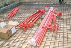
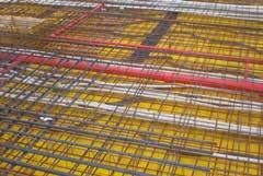
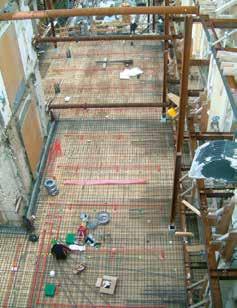
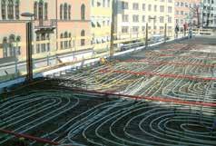
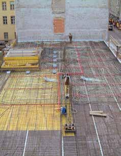
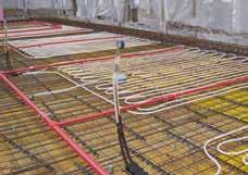
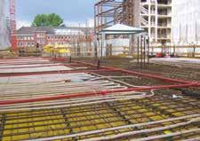
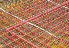
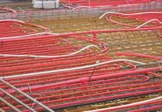
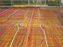
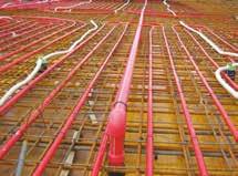
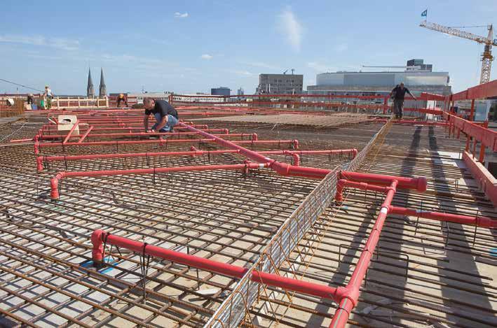
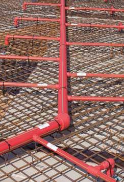
5 CONTENT TABLE OF CONTENTS Laying of aquatherm re pipe in the concrete Part 1: 51 Connecting of pipe work to the sprinkler outlet Part 2: 59 Pressure test of pipe work installation as strength test an leak test Part 3: 59 What must be consiere uring the concreting process? Part 4: 60 Access to connection of the pipe work in concrete Part 5: 61 Briging of builing joints Part 6: 61 Potential equalizing Part 7: 61 Pressurizing in the aquatherm re pipe supply uring the concreting process Part 8: 61 Influence of the concrete to the applie compouns Test Leakage test/pressure iagram Test recor aquatherm re pipe system installation Form: Enquiry for the chemical resistance References
6 SERVICE SERVICE TECHNICAL HOTLINE +49 (0) { { Parent plant Attenorn aquatherm GmbH Biggen Attenorn Phone: +49 (0) Fax: +49 (0) Subsiiary Raeberg aquatherm GmbH Wilhelm-Rönsch-Str Raeberg Phone: +49 (0) Fax: +49 (0) Fiel staff In aition to the regular training service at Attenorn an Raeberg aquatherm fiel staff are available to assist customers, on site, throughout Germany. Training service In aition to training service through the merchant network aquatherm offers its customers training, free of charge, at its training centres at Attenorn an Raeberg. Fair aquatherm is represente on all important fairs relevant for the sanitary an heating sector in Germany or abroa with its own exhibition booth. For more information regaring fairs near to you, please visit internet page: 6


7 SERVICE CERTIFICATIONS IN ACCORANCE WITH ISO 9001, & Since 1996 aquatherm has been meeting the requirements of the certifiable quality management system accoring to IN ISO The 2012 TÜV certificate was extene by the environmental management system accoring to ISO an currently by the energy management system accoring to ISO This success is a great contribution an represents a further step to strengthen our competitive position an to meet the high requirements an the responsiblity for our customers, partners an the environment. Management System ISO 9001:2008 ISO 14001:2004 ISO 50001: I Laboratory The aquatherm laboratory: From the testing of granulate through to the finishe prouct the customer can be assure of only the highest quality proucts. Software-Service The aquatherm software service provies atanorm-files, an inepenent graphical program (linear), an the appropriate training. Brochures etc. No matter whether brochures, catalogues or prouct lists: Our in-house marketing epartment evelops everything itself. You can ownloa all ocuments as pf from our website For printe copies, please sen an to info@aquatherm.e. SERVICE 7

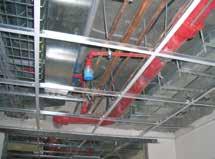
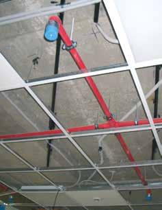
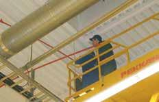
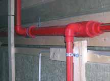
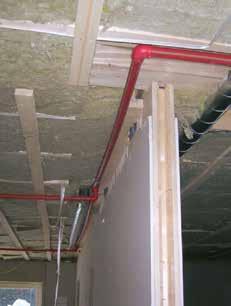
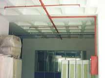
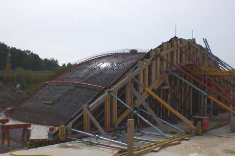
8 re GENERAL aquatherm re AVANTAGES Certifie an quality inspecte Connection by fusion weling Resistant against corrosion an chemicals No accumulation of corrosion proucts Low pipe roughness factor an high abrasion resistance Heat- an soun-insulating characteristics High impact strength Leak-proof connection of pipe an fitting by fusion technique Not easily flammable acc. to IN , builing material class B1 Low weight compare to metal pipes Short processing time No gaskets sealing elements are not require 3-layer pipe with fibre glass reinforce inner layer Conceale fire protection Reuction of structural work costs by laying in concrete Wel-in sale aquatherm re pipe offers an extensive range of pipes an fittings for the installation of fire sprinkler systems. aquatherm re pipe is: Connection by fusion weling No sealants or ahesives are require for this permanent connection. Corrosion-proof Prevents the clogging of the sprinkler with corrosive material. This ensures a long, low-maintenance service life as well as failure-free functioning of the system. The prouction of pipes an fittings is controlle accoring to the highest quality stanars on most moern injection mouling machines an extrusion lines. The high quality of our proucts is guarantee by extensive controls of incoming goos an the prouction process. The aquatherm quality management system is certifie accoring to IN EN ISO 14001:2004, 9001:2008 an 50001:2011. The system is base on a fibre reinforce polypropylene pipe (faser composite pipe) prouce in a multi-layer extrusion process. The material fusiolen PP-R FS, use for the pipe prouction, is a plastic whose properties are esigne for the special emans of the fiels of application. Both, the installer s request for easier processing an the eman for maximum safety in later application, was regare uring the evelopment. 8


9 GENERAL re PP-R-layer Faser layer PP-R-layer PROCESSING Fusion technique By the fusion of pipe an fitting the plastic melts to a homogeneous material unit. Pipe an fitting are heate quickly with specially provie weling tools an joine together finishe! ouble material thickness at the joint giving ouble safety at the otherwise critical point of a pipe system. A permanent leakproof connection is create with the aquatherm fusion technique. 9


10 GENERAL PROCESSING Wel-in sale technique Branches can easily be mae by wel-in sales, even post-installation. Material costs an processing time are reuce by using wel-in sales. Whereas in case of tees three joints are to be processe, work is limite to mounting the sale an the branch pipe only. Simply rill the pipe; heat up the sale, pipe wall an surface; connect the parts. Finishe! 10


11 GENERAL INTERNATIONAL APPROVALS for the application as sprinkler lines Fire protection requirements an stanars for planning an construction of sprinkler systems vary locally. Thus, the application of aquatherm re pipe in any case has to be agree an coorinate with the local national fire protection authorities, the constructor an the builing insurers. Further certification either national or local are in process. Germany Polan Austria Hong Kong New Zealan Icelan FEERAL STATE ESTABLISHMENT THE ALL-RUSSIAN RESEARCH INSTITUTE FOR FIRE PROTECTION (FGU VNIIPO) Russia Australia Great Britain Spain New Zealan 11

12 GENERAL curaflam collar by oyma conlit pipe wraps by Rockwool HANLING Transport an storage aquatherm re pipe pipes can be store in all outsie temperatures. Pipes shoul be store an transporte flat an fully supporte along their length. Bening pressures are to be avoie. High impact shoul be avoie at externely low temperatures. Although aquatherm re pipe pipes are extremely robust, it is recommene to treat the material always with care. UV resistance Pipes from fusiolen PP-R FS shoul not be installe (without protection) where subject to UV-raiation. All aquatherm re pipe pipes an fittings are supplie in UV-protecte packaging to brige transport an assembly time. Ultraviolet rays have an influence on all high polymeric plastics. Hence, pipes shoul not be store unprotecte outsie for a long time. The maximum storage time is (outsie) 6 months. Fire bulkheaing All fire prevention systems which can prove equivalent licensing are suite for the aquatherm re pipe system. Proceures for aitional repair Cut out amage/leaking section an replace as for a new installation or repair with pipe repair stick (page 45). Chemical resistance On account of the special material qualities aquatherm re pipe pipes an fittings provie extensive chemical resistance. aquatherm re pipe transition connections an elements with brass inserts are not suitable for all meia. The compatibility shoul be aske at aquatherm with meia eviating from water. Please use the Enquiry for the chemical resistance on page 66. Pipe friction loss The pressure loss cause by friction is to be calculate hyraulically with the Hazen-Williams-formula. The value to be use for C is 150, applicable for calculations of sprinkler installations an water supply. Equivalent lengths for the aquatherm re pipe sprinkler pipe system The equivalent lengths of transition pieces, threae connexions an tees (flow irection: straight) can be eequate with the socket values. Pipe imension Pipe series SR 7,4 SR 7,4 SR 7,4 SR 7,4 SR 7,4 SR 7,4 SR 7,4 SR 7,4 SR 7,4 SR 7,4 SR 11 Nominal iameter N15 N20 N25 N32 N40 N50 - N65 N80 - N125 Outer iameter aquatherm re pipe Article 20,0 mm 25,0 mm 32,0 mm 40,0 mm 50,0 mm 63,0 mm 75,0 mm 90,0 mm Equivalent pipe length in (m) Socket 0,17 0,22 0,30 0,40 0,52 0,70 0,86 1,07 1,36 1,58 2,44 Reuction of 1 imension Reuction of 2 imensions 0,20 0,27 0,37 0,48 0,63 0,83 1,03 1,28 1,63 1,90 2,93 0,27 0,36 0,49 0,64 0,84 1,11 1,37 1,71 2,17 2,53 3,91 Elbow < ,51 0,67 0,91 1,20 1,57 2,09 2,57 3,20 4,07 4,74 7,33 Elbow < 45 0,25 0,33 0,46 0,60 0,78 1,04 1,28 1,60 2,03 2,37 3,66 Stanar tee or cross flow irection branch 0,74 0,98 1,34 1,76 2,30 3,06 3,76 4,70 5,96 6,96 10,75 110,0 mm 125,0 mm 160,0 mm 12

13 PROUCTS PIPE, FITTINGS Material: PP-R FS Pipe series: SR 7,4 Packing Unit: Colour: straight length à 6 m re/4 green stripes i aquatherm re pipe PIPE SR 7,4 / B1 Art. no. imension mm PU iameter [mm] Wall thickness s [mm] Internal iameter i [mm] Water content [l/m] x 2, ,8 14,4 0,163 0, x 3, ,5 18 0,254 0, x 4, ,4 23,2 0,423 0, x 5, ,5 29 0,660 0, x 6, ,9 36,2 1,029 0, x 8, ,6 45,8 1,647 1, x 10, ,3 54,4 2,323 2, x 12, ,3 65,4 3,358 3, x 15, ,1 79,8 4,999 4, x 17, ,1 90,8 6,472 5,974 aquatherm re pipe PIPE SR 11 / B1 Art. no. imension mm PU s iameter [mm] Wall thickness s [mm] Internal iameter i [mm] Water content [l/m] x 14, ,6 130,8 15,792 6,940 Weight [kg/m] Weight [kg/m] L z aquatherm re pipe SOCKET / B1 Art. no. imension mm PU L z ,5 0, , ,5 4,5 43 0, ,5 6,5 52 0, , ,5 5,5 84 0, ,5 6, , ,5 6, , , ,819 Weight [kg/m] Art. no.=article number, PU=Packing unit, =iameter (mm), s=wall thickness (mm), i =internal iameter (mm), f=female threa, m=male threa 13
14 l L z z L z L l L z PROUCTS FITTINGS 1 aquatherm re pipe REUCER / B1 SR 7,4 Art. no. imension mm PU 1 L l z Weight socket weling / , ,5 0, / , / ,5 11,5 43 0, / ,5 12,5 43 0, / , , / ,5 12,5 68 0, / ,5 13,5 84 0, / ,5 27,5 17,5 84 0, / , , / , / , / , , / ,5 0, / ,5 0, / ,5 68 0, / ,5 84 0,363 aquatherm re pipe REUCER / B1 SR 11 Art. no. 1 imension mm PU 1 L z Weight butt weling / , / , aquatherm re pipe REUCING SOCKET / B1 female/female Art. no. imension mm PU 1 L l z 1 Weight / , , / , , / ,297 14
15 l z z z FITTINGS z l PROUCTS aquatherm re pipe ELBOW 90 / B1 SR 7,4 Art. no. imension mm PU socket weling z l Weight ,5 27 0, ,5 29,5 34 0, , ,5 52 0, ,5 68 0, , , ,5 68, , , , ,5 116, ,026 aquatherm re pipe ELBOW 90 / B1 SR Art. no. imension mm PU 11 butt weling z Weight ,976 z1 l1 aquatherm re pipe ELBOW 90 / B1 female/male Art. no. imension mm PU z l l1 z1 Weight ,5 29,5 25,5 15 0, ,5 29, ,5 17 0, ,5 0, , ,5 26 0,081 15
16 l z z l z PROUCTS FITTINGS aquatherm re pipe ELBOW 45 / B1 SR 7,4 Art. no. imension mm PU socket weling z l Weight ,5 29,5 0, , ,5 25,5 43 0, , , , , ,5 84 0, ,5 46, , ,5 52, , ,5 60, , ,281 aquatherm re pipe ELBOW 45 / B1 SR Art. no. imension mm PU 11 Avice: Special elbows in iverse egree sizes on request butt weling z Weight ,463 l1 z1 aquatherm re pipe ELBOW 45 / B1 female/male Art. no. imension mm PU z l l1 z1 Weight ,5 29,5 19,5 9 0, ,5 0, ,5 25, ,5 11,5 0, , ,5 13,5 0,059 16
17 z l z FITTINGS L z1 z1 PROUCTS aquatherm re pipe TEE / B1 SR 7,4 Art. no. imension mm PU l z L z1 Weight socket weling , , ,5 14, , ,5 15, , , , , , , ,5 0, ,5 38, ,5 0, , , ,5 76, ,5 2,693 L aquatherm re pipe TEE / B1 SR 11 Art. no. imension mm PU butt weling z L Weight ,838 17
18 z l z l z1 l ste 2017 PROUCTS FITTINGS z2 L z 1 1 L aquatherm re pipe REUCING TEE / B1 SR 7,4 Art. no. imension mm PU z 1 l1 z1 1 2 L z2 Weight socket weling x25x , ,5 14, ,5 0, x20x , ,5 0, x20x , , x20x , , ,5 22,25 0, x20x ,5 29, , x25x , x25x , x32x , ,5 22, ,5 0, x32x ,5 26, , x40x , , x32x , ,5 35, ,5 0, x40x , , ,5 0, x50x , , ,5 0, x40x , , ,5 0, x50x , , ,5 0, x63x , , ,5 0, x40x , , x50x , , x63x , , x75x , x63x , , x75x ,5 57, , x90x , x75x , ,5 76, ,5 2, x90x , ,5 76, ,5 2, x110x , ,5 76, ,5 2, Art.N Artikelliste L aquatherm re pipe REUCING TEE / B1 SR 11 Art. no. imension mm PU 1 1 L l z Weight Segmentgeschweißter Artikel butt weling x75x , x90x ,517 18
19 1 1 z l z L PROUCTS FITTINGS aquatherm re pipe CROSS / B1 Art. no. imension mm PU z L Weight , ,101 aquatherm re pipe REUCING TEE / B1 Art. no. imension mm PU 1 z1 1 l1 z l Weight / , , ,5 0, / , , , , / , , , / , ,5 0, / , , ,5 0, / , , ,5 0, / , , ,5 0,762 l1 z1 19
20 L z L z PROUCTS FITTINGS aquatherm re pipe EN CAP / B1 SR 7,4 Art. no. imension mm PU socket weling L z Weight ,5 29,5 0, , , ,5 52 0, , , ,5 84 0, ,5 28, , ,5 34, , , ,872 aquatherm re pipe EN CAP / B1 SR 11 Art. no. imension mm PU L z Weight butt weling ,00 14, ,787 20
21 z L z L L L L L L FITTINGS Gruppe Re Pipe Seite 19 PROUCTS 1 aquatherm re pipe BASE PART FOR SPRINKLER OUTLET Art. no. PU m/st 1 L Weight for visible sprinkler 25 47, ,013 aquatherm re pipe BASE PART FOR SPRINKLER OUTLET Art. no. Gruppe Re Pipe Seite 19 PU 1 L Weight for covere sprinkler ,034 1 Gruppe Re Pipe Seite 19 Gruppe Re Pipe Seite aquatherm re pipe UPPER PART FOR SPRINKLER OUTLET for visible sprinkler Art. no. imension PU 1 L Weight / ,4 23,2 30 0, / ,6 30,2 30 0, ,6 35,2 30 0,021 aquatherm re pipe UPPER PART FOR SPRINKLER OUTLET for covere sprinkler PU SW Art. no. imension 1 L Weight R / ,2 43 0, / ,2 43 0, ,2 43 0,056 1 SW aquatherm re pipe PLUG FOR SPRINKLER OUTLET R Art. no. imension PU R L z SW Weight /2 25 1/ ,5 12,5 15 0, /4 25 3/ ,5 17 0, ,076 21
22 l z L l z L l z L L z L L PROUCTS FITTINGS Gruppe aquatherm re pipe TEMPORARY PLUG FOR PLASTER WORKS Gruppe mae of PE foam Re Pipe Re Pipe PU Art. no. imension Seite 20 Seite 20 L Weight for , -82, ,5 42 0, for , -92, ,003 aquatherm re pipe SPRINKLER OUTLET Art. no. imension Gruppe Re Pipe PU Seite 20 L Weight / ,1 44,1 6,5 0, / ,1 50,1 6,5 0, ,1 61,1 6,5 0,043 SW SW SW aquatherm re pipe PLUG FOR SPRINKLER OUTLET R PU Art. no. imension R L z SW Weight G Plug for sprinkler outlet 1 1/4 G /4 18,2 15, ,203 G Plug for sprinkler outlet 1 1/2 G / , , Plug for sprinkler outlet ,5 17 0,443 SW G2 G1 aquatherm re pipe PLUG FOR PRESSURE TEST Art. no. imension PU G1 G2 z l L SW Weight threa 1/2" /2 1/8 9 21, , threa 3/4" /4 1/8 9 21, , threa 1" /8 8,5 21, ,126 aquatherm re pipe COUPLING PLUG 1/ /2" for Art-. No , -13, ,
23 z l z l z1 z1 L L z2 z2 FITTINGS R2 R2 PROUCTS SW SW NEW aquatherm re pipe COMPENSATING JOINT Art. no. imension PU R1 z1 R2 z2 L SW Weight /4 mx3/8 f 10 3/4 17,5 3/8 15, , /4 mx1/2 f 10 3/4 19,5 1/2 13, , mx1 f ,067 1 R1 R mx1/2 f ,5 1/2 13, , aquatherm re pipe WEL-IN SALE NEW NEW SR Art. no. imension mm PU 1 2 l z Weight 7,4 11 socket weling / ,5 29,5 0, / ,5 32,5 34 0, / , ,5 0, / ,5 37,5 34 0, / ,5 44,5 29,5 0, / , , / ,5 43 0, / ,5 50,5 29,5 0, / , , / ,5 43 0, / , / , ,5 0, / ,5 57, , / , / ,5 52 0, / , ,5 0, / ,5 67,5 34 0, / , / ,5 52 0, / ,5 68 0, / ,5 75,50 29,5 0, / , , / ,5 43 0, / , / , / ,030 butt weling / , , / , , / , / ,368 With wel-on surface an wel-in socket to be fuse with the inner wall of the pipe. The require tools for the fusion of aquatherm re pipe wel-in sales are liste on page 34: aquatherm re pipe wel-in sale tools Art. no aquatherm rill Art. no
24 L z2 l L z2 l L z2 z1 l L PROUCTS FITTINGS aquatherm re pipe WELABLE FLANGE AAPTER / B1 with joint ring SR 1 7,4 Art. no. imension mm PU Art.N Artikelliste 2015 L z1 1 l z2 Weight socket weling , , ,071 Seite , , , , , , ,5 18, ,5 3 0, ,724 1 aquatherm re pipe WELABLE FLANGE AAPTER / B1 with joint ring SR 11 Art. no. imension mm PU L z1 1 l z2 Weight butt weling , , n 2 aquatherm re pipe STEEL FLANGE Art. no. imension mm PU 1 2 L n Weight ,5 4 1, ,5 4 1, ,5 4 1, , , , , , ,106 24
25 l z R 1 c l z R 1 c Seite 38 PROUCTS FITTINGS SW1 SW2 Art.N Re Pipe Seite 40 z l aquatherm re pipe COUPLING SCREW / B1 imension Art. no. PU mm L l z SW1 SW2 Weight l z ,5 18, , , , , , , , ,5 17, ,998 Incl. 2 flange aapters with gasket TRANSITION PIECE L z1 l1 aquatherm re pipe BACK PLATE ELBOW / B1 Art. no. imension PU l z l1 z1 1 L c R Weight mm x 1/2" ,5 29,5 31,5 18, /2 0, mm x 3/4" /4 0,111 25
26 R R R PROUCTS TRANSITION PIECE z aquatherm re pipe TRANSITION PIECE / B1 for the connection to sprinkler outlets roun Art. no. z imension l L SW Art.N PU Re Pipe Seite 24 l z L R Weight l 20 mm x 1/2 f , ,5 40,5 1/2 0, L 25 mm x 1/2 f ,5 26,5 38,5 42,5 1/2 0, mm x 3/4 f ,5 24,5 43,5 40,5 3/4 0, mm x 3/4 f ,5 25,5 43,5 43,5 3/4 0, mm x 1/2 f /2 0, mm x 1/2 f , ,5 1/2 0, mm x 3/4 f , /4 0,105 z SW aquatherm re pipe TRANSITION PIECE / B1 with hexagon (*suitable for the connection to sprinkler outlets) l L Art. no. imension PU l z L R SW Weight mm x 1/2 f , ,5 50,5 1/2 24 0, mm x 3/4 f ,5 43,5 50 3/4 31 0, mm x 1/2 f ,5 52 1/2 24 0, mm x 3/4 f ,5 50 3/4 31 0, mm x 3/4 f ,5 53 3/4 31 0, * 32 mm x 1 f ,5 41, , , * 40 mm x 1 f , , mm x 1 1/4 f , /4 50 0, mm x 1 1/4 f , /4 50 0, mm x 1 1/2 f , /2 55 0, mm x 1 1/2 f , ,5 1 1/2 55 0, mm x 2 f , , mm x 2 f , mm x 1/2 f ,5 53 1/2 24 0, mm x 1/2 f , /2 24 0,094 26
27 l z R 1 l z R 1 R e Pipe eite 25 TRANSITION PIECE PROUCTS SW aquatherm re pipe TRANSITION PIECE / B1 with hexagon Art. no. l1 z1 imension PU L z R SW z2 Weight mm x 1/2 m , ,5 1/ , mm x 3/4 m , ,5 3/ , mm x 1/2 m ,5 1/ , mm x 3/4 m ,5 51,5 38,5 3/ , mm x 3/4 m ,5 51,5 38,5 3/ , mm x 1 m ,5 60, , mm x 1 1/4 m / , mm x 1 m , , mm x 1 1/4 m , / , mm x 1 1/4 m , / , mm x 1 1/2 m , / , mm x 1 1/2 m , ,5 1 1/ , mm x 2 m , ,5 0, mm x 2 m ,5 0, mm x 2 1/2 m / ,7 1, mm x 3 m , mm x 4 m ,816 L z z2 Art.N Re Pipe Seite 25 l1 z1 aquatherm re pipe TRANSITION ELBOW / B1 Art. no. imension PU l z l1 z1 1 R Weight mm x 3/4 f , /4 0, mm x 1/2 f ,5 29,5 31,5 18,5 37 1/2 0, mm x 3/4 f /4 0, mm x 1/2 f ,5 17, ,5 18,5 37 1/2 0, mm x 1/2 f /2 0, mm x 3/4 f ,5 9, /4 0, mm x 1 f ,5 44,5 60,5 1 0, mm x 1/2 f ,75 21, /2 0, mm x 1 f , ,265 27
28 SW R l1 z1 e 6 PROUCTS TRANSITION PIECE z l R 1 l1 NEW NEW aquatherm re pipe THREAE BRANCH TEE / B1 k Art. l no. imension PU l z l1 z1 1 R SW Weight x 1/2 f x 20 mm , , /2-0, x 3/4 f x 20 mm , /4-0, x 1/2 f x 25 mm ,5 18, /2-0,088 Art.N Re Pipe Seite x 3/4 f x 25 mm /4-0, x 1/2 f x 32 mm /2-0, x 3/4 f x 32 mm ,5 9, /4-0, x 1 f x 32 mm ,5 13, , x 1/2 f x 40 mm , /2-0, x 3/4 f x 40 mm , ,5 27,5 52 3/4-0, x 1 f x 40 mm , , x 1 f x 50 mm , ,5 41,5 68, , x 1 1/4 f x 50 mm , ,5 47, /4 50 0, x 1/2 f x 50 mm , ,5 31,5 43 1/2-0, x 3/4 f x 50 mm , ,5 31,5 43 3/4-0,243 l1 aquatherm re pipe LOOSE NUT AAPTER / B1 Length: 100 mm threae, with gasket Art. no. imension PU l l1 k R SW Weight mm x nut threa , mm x nut threa 1 1/ /4 46 0, mm x nut threa 1 1/ /2 52 0, mm x nut threa , mm x nut threa 2 1/ /4 72 0, mm x nut threa 2 1/ /2 80 0, mm x nut threa 2 3/ /4 89 0, mm x nut threa 3 1/ / , mm x nut threa ,238 l k 28
29 R R PROUCTS SW l z l1 aquatherm re pipe FEMALE PART UNION / B1 ISO-Norm Art. no. imension PU l z R SW l1 Weight nut threa 1 x 20 mm , , ,182 Art.N Re Pipe Seite nut threa 1 1/4 x 25 mm ,5 1 1/ , nut threa 1 1/2 x 32 mm ,5 51, / , nut threa 2 x 40 mm , , nut threa 2 1/4 x 50 mm , / , nut threa 2 3/4 x 63 mm / , nut threa 3 1/2 x 75 mm / ,818 L z aquatherm re pipe metal composite fittings are manufacture from Fusiolen PP-R FS an brass. SW L z aquatherm re pipe COUNTERPART / B1 with weling socket an male threa for ISO-threae joints Art. no. imension PU L z R SW Weight mm x 1 m , , , mm x 1 1/4 m ,5 1 1/4 31 0, mm x 1 1/2 m ,5 58, /2 39 0, mm x threa 2 m , , mm x threa 2 1/4 m , /4 55 0, mm x threa 2 3/4 m , /4 67 1, mm x threa 3 1/2 m /2 67 1,574 29
30 z l z2 z l z2 L z l PROUCTS 1 TRANSITION PIECE aquatherm re pipe TRANSITION PIECE FOR GROOVE CONNECTION / B1 Art. no. imension PU L z 1 Weight mm x 1 groove connection , ,5 0, mm x 1 1/4 groove connection , ,20 0, mm x 1 1/2 groove connection , ,25 0, mm x 2 groove connection ,3 0, mm x 3 groove connection ,9 1, mm x 4 groove connection ,5 82, ,3 2, mm R x 5 groove connection SW ,046 R SW 1 1 aquatherm re pipe WEL-IN SALE WITH FEMALE THREA / B1 Art. no. imension PU 1 l z z2 R SW Weight /25 mm x 1/2 f ,5 1/2 24 0, /25 mm x 1/2 f ,5 1/2 24 0, /25 mm x 1/2 f , ,5 1/2 24 0, /25 mm x 1/2 f , ,5 1/2 24 0, /25 mm x 1/2 f ,5 1/2 24 0, /25 mm x 1/2 f ,5 1/2 24 0, /25 mm x 1/2 f , ,5 1/2 24 0, /25 mm x 1/2 f ,5 1/2 24 0, /25 mm x 3/4 f ,5 3/4 31 0, /25 mm x 3/4 f ,5 3/4 31 0, /25 mm x 3/4 f , ,5 3/4 31 0, /25 mm x 3/4 f , ,5 3/4 31 0, /25 mm x 3/4 f ,5 3/4 31 0, /25 mm x 3/4 f ,5 3/4 31 0, * 75/32 mm x 1 f , , * 90/32 mm x 1 f , * 110/32 mm x 1 f , * 125/32 mm x 1 f , ,091 with female threa an hexagon socket, with wel-in wel-on surface an wel-in socket to be fuse with the inner wall of the pipe The require tools for the fusion of aquatherm re pipe wel-in sales are liste on page 34: - Wel-in sale tools, Art. no aquatherm rill, Art. no *suitable for the connection to sprinkler outlets 30
31 h l1 PROUCTS aquatherm re pipe BALL VALVE PP/MS / B1 L z Art. no. imension mm PU L z h l1 Weight ,50 29, , , , , , , ,552 aquatherm re pipe metal composite fittings are manufacture from Fusiolen PP-R FS an brass. CUTTER & WELING EVICES aquatherm PIPE CUTTER Art. no. for pipe imensions PU ø mm ø mm ø mm 1 aquatherm PIPE CUTTER Art. no. for pipe imensions PU ø mm 1 Important: o not cut the aquatherm re pipe pipes with customary hack saws. aquatherm re pipe pipes can be cut with customary saws equippe with saw blaes suitable for plastic. ORBITAL CIRCULAR SAW Art. no. for pipe imensions PU ø mm 1 This orbital circular saw can be orere irectly from Rothenberger with Art. no ( High-performance orbital circular saw for fast, precise, perfectly aligne an right-angle cutting of plastic pipes mm at the builing site or in the workshop. CUTTING ISC FOR PLASTIC Art. no. imension Borehole PU ø 125 mm 22,2 mm ø 230 mm 22,2 mm 1 Application: for each angle griner esign: iamon galvanize cutting isc 31
 Art. no.")
32 aquatherm fusiotherm fusiotherm fusiotherm aquatherm PROUCTS aquatherm MANUAL WELING EVICE (500 W) Art. no. for pipe imensions PU ø mm 1 aquatherm With base an case for tools aquatherm MANUAL WELING EVICE (800 W) Art. no. for pipe imensions PU ø mm 1 With base an case for tools aquatherm aquatherm MANUAL WELING EVICE (1400 W) Art. no. for pipe imensions PU ø mm 1 With base an case for tools aquatherm WELING MACHINE (1400 W) Art. no. for pipe imensions PU ø mm 1 incl. weling tools mm, roll stan an wooen transport case aquatherm ELECTRIC WELING JIG Art. no. for pipe imensions PU ø mm 1 incl. spare battery, charging station an metal case Support: Art. no on request aquatherm aquatherm BASE FOR ART. NO Art. no. imension PU aquatherm WELING MACHINE (1400 W) LIGHT Price Art. no. for pipe imensions PU ø mm 1 aquatherm manual weling evice (1400 W) an wooen transport case BUTT WELING MACHINE WIOS Art. no. imension PU 50352* ø mm 1 32 The butt-weling-machine can be purchase irectly from Wios ( * Also available in esign with 110 volt (Art. no = ø mm / = ø mm / = ø mm / = ø mm / = ø mm)
33 PROUCTS BUTT WELING MACHINE RITMO Art. no. for pipe imensions PU ø mm 1 incl. wooen transport box. The butt weling machine can be obtaine irectly from Ritmo ( aquatherm TEMPERATURE MEASURING EVICE Art. no. imension PU to check the correct weling temperature aquatherm THERMOCOLOUR PENCIL Art. no. imension PU to check the correct weling temperature aquatherm CLEANING WIPES Art. no. imension PU Box with 100 towels 1 for electrofusion sockets aquatherm WELING TOOL Art. no. imension mm PU aquatherm REPAIR KIT Art. no. imension PU mm mm 1 to close pipe holes up to 10 mm (pipe repair stick Art. no ) aquatherm re pipe REPAIR STICK Art. no. imension PU /11 mm 1 Material: Fusiolen PP-R FS to close pipe holes up to 10 mm. Tool: aquatherm green pipe repair kit (Art. no ). 33
34 PROUCTS WELING TOOLS & RILLS aquatherm WELING TOOL for weling sales of Art. no an Art. no. imension PU x 20/25 mm x 20/25 mm x 20/25 mm x 32 mm x 20/25 mm x 32 mm x 40 mm x 20/25 mm x 32 mm x 40 mm x 20/25 mm x 32 mm x 40 mm x 50 mm x 20/25 mm x 32 mm x 40 mm x 50 mm x 63 mm x 20/25 mm x 32 mm x 40 mm x 50 mm x 63 mm x 75 mm x 90 mm 1 aquatherm RILL for installation of wel-in sales Art. no. imension PU & 25 mm (for pipes mm) mm mm * 50 mm * 63 mm */** 75 mm */** 90 mm 1 * may only be use in fixe rilling machines! ** tool holer MK4 aquatherm re pipe EXTRACTION TOOL for sprinkler outlet Art. no Art. no. imension PU NEW aquatherm re pipe AJUSTING TOOL for compensating joint with aapter 3/8 male, 1/2 male, 1 male Art. no. imension PU


35 FUSION PART A: Mounting of the weling tools 1. Important! Only use original aquatherm weling evices an aquatherm weling tools. 2. Assemble an tighten the col weling tools manually. 3. All weling tools must be free from impurities. Check, if they are clean before assembling. If necessary, clean the weling tools with a nonfibrous, coarse tissue an with spirit. 4. Place the weling tools, so that there is full surface contact between the weling tool an the weling plate. Weling tools over Ø 40 mm must always be fitte to the rear position of the weling plate. 5. Plug in the weling evice an check, if operating lamp is on. epening on the ambient temperature it takes minutes to heat-up the weling plate. The heat-up phase ens, when the temperature pilot lamp blinks an a signal is auible. RIGHT Electric power supply: The power supply must coincie with the ata on the type plate of the weling evice an must be protecte accoring to the local regulations. To avoie high power loss, the conuctor cross-section of the use extension cables must be selecte accoring to the power input of the weling evices. WRONG 35

36 FUSION hanle Temperature pilot lamp (yellow) glows constantly while the heatup phase an blinks when the weling temperature is achieve Operating lamp (green) glows constantly as soon as the evice is conntecte with the power supply system. Heating plate Weling tool PART A: Heat-up phase 6. uring the heat-up phase tighten the weling tools carefully with the Allen Key. Take care that the tools fully contact the weling plate. Never use pliers or any other unsuitable tools, as this will amage the coating of the weling tools. 7. The require temperature to wel the aquatherm re pipe system is 260 C. Acc. to VS-Weling Guielines, the temperature of the weling evice has to be checke at its tool before starting the weling process. This has to be one with a fast inicating thermometer or alternatively with an aquatherm green pipe thermocolour crayon. (see Fusion part B, item 2 ) 8. A tool change on a heate evice requires another check of the weling temperature at the new tool (after heat-up phase). 9. If the evice has been unplugge, i. e. uring longer breaks, the heatup process has to be restarte (from item 5). 10. After use unplug the weling evice an cool own. Water must never be use to cool the weling evice, as this woul estroy the heating resistances. ATTENTION: First weling at the earliest 10 minutes after reaching the weling temperature VS 2207, Part 11. PART A: Hanling 11. Protect aquatherm weling evices an tools against impurities. Burnt-it particles may result in an incorrect fusion. The tools may be cleane with aquatherm cleaning wipes, Art. no Always keep the burnt-in weling tools ry. If necessary, ry them with a clean, nonfibrous tissue. 12. For perfect fusion, amage or irty weling tools must be replace, as only unamage tools ensure a perfect fusion weling. 13. Never attempt to open or repair a efective evice. Return the efective evice for repair. 14. Check the operating temperature of the aquatherm green pipe weling evices regularly by means of suitable measuring instruments. PART A: Guielines 15. For the correct hanling of weling machines the following must be observe: General Regulations for Protection of Labour an Prevention of Accients an particularly the Regulations of the Employers Liability Insurance Association of the Chemical Inustry regaring Machines for the Processing of Plastics, chapter: Weling Machines an Weling Equipment. 16. For the hanling of the aquatherm weling machines, evices an tools please observe General Regulations VS 2208 Part 1 of the German Association for Weling Engineering, Registere Society (eutscher Verban für Schweißtechnik e. V.). 36


 Suitable measuring instruments must")


 it will change after 3 or more secons.")
37 FUSION PART B: Checking of evices an tools 1. Check, if the aquatherm weling evice an tool correspon to the guielines Fusion Part A. 2. All evices an tools in use must have reache the require operating temperature of 260 C in use. This nees a separate, compulsory test, acc. to VS-Weling Guieline. The control of the operating temperature can be mae with fast inicating thermometers. Measurement of temperature at the aquatherm manual weling evice (800 W ) Suitable measuring instruments must offer a temperature measurement of up to 350 C with a high accuracy. Alternatively it is also possible to check the weling temperature with the aquatherm thermocolour crayon. The application of the special thermocolour chalk in the aluminium crayon enables an exact reaing with a tolerance of +/- 5 K to heate surfaces. Application: After the temperature pilot lamp of the weling evice has inicate the en of the heat-up perio, put a firm chalk line on the heate external surface of the weling tool. The colour must change within 1 2 secons. Temperature control aquatherm weling evice (1400 W) If the temperature is too high, the colour will change immeiately an if it is too low (below 260 C) it will change after 3 or more secons. If the colour oes not change within 1 2 secons, another temperature test has to be carrie out, respectively the control of the weling evice is require. Temperature control aquatherm weling machine before after Temperature control with the aquatherm thermocolour crayon Measurement of temperature at the aquatherm butt-weling machine 37


38 FUSION PART B: Preparation for the fusion 3. Cut the pipe right-angle to the pipe axis. Only use aquatherm green pipe pipe cutters or other suitable cutting tools. Take care that the pipe is free from burrs or cutting chips an remove if necessary. 4. Mark the weling epth at the en of the pipe with the enclose pencil an template. 5. Mark the esire position of the fitting on the pipe an/or fitting. The auxiliary markings on the fitting an the continue line on the pipe may be use as a help. The fusion is subject to the following ata Cutting of the pipe Pipe external-ø Weling epth Heat-up time Weling time Cooling time mm mm sec. VS sec min , , , , , , , , , , Marking of the weling epth The General Guielines for Heate Socket Weling acc. to VS 2207 Part 11 apply. 38

39 FUSION Warming Joining, fixing an aligning! PART B: Heat-up of pipe an fittings PART B: Setting an alignment 6. Push the en of the pipe, without turning, up to the marke weling epth into the weling tool an at the same time the fitting, without turning, as far as it will go on the tool. It is essential to observe the above mentione heating times. Pipes an fittings of the imensions Ø 75 to 125 mm may only be wele with weling evice Art. no (or with machine Art. no ). On using the aquatherm green pipe weling machine Art. no , a separate operating instruction has to be observe. ATTENTION: The heating time starts, when pipe an fitting have been pushe with the correct weling epth on an in the weling tool. Not before! 7. After the stipulate heat-up time quickly remove pipe an fitting from the weling tools. Join them immeiately, without turning, until the mark weling epth is covere by PP-bea of the fitting. ATTENTION: o not push the pipe too far into the fitting, as this woul reuce the bore an in an extreme case may close the pipe. 8. The joint elements have to be fixe uring the specifie processing time. Use this time to correct the connection. Correction is restricte to the alignment of pipe an fitting. Never turn the elements or align the connection after the processing time. 9. After the cooling perio the fuse joint is reay for use. The result of the fusion of pipe an fitting is a permanent material joining of the system elements. Unrivalle connection technique with security for a life-time! 39
40 FUSION VISUAL INSPECTION OF FUSION SEAM Normally on fusioning a bea is forme aroun the entire circumference at the ege of the socket. This bea is an inication of proper weling. Incorrect shape of bea ifferent shape of bea (b) or non-existent bea at one or at both ens (a) (partial or total extent), resulting from: Temperature of heating tool is too low (a) Heat-up time too short (a) Unacceptable tolerances (a an b) Excessive temperature of heating tool (b) Heat-up time too long (b) Single shape of bea, resulting from: Heat-up time too short Temperature of heating tool is too low Unacceptable tolerances Heat-up of only one weling part Excessive melting, resulting from: Temperature of heating tool is too high Misaligne movement of weling-part, e.g. by inaequate fixing Unacceptable tolerances Elbow variance Partially or ouble-sie incline wele pipe into the socket without or with slight bracing, resulting from: Machinery efect False installation Acceptable, if e 2 mm 5 Mistake of boning by improper pipe insertion, resulting from: Heat-up time too short Pipe ens not at 90 (right-angle) Heating temperature too low Axial movement uring cooling time Change-over time too long Acceptable up to 0.1 x an 0.15 x socket epth 40
41 FUSION VISUAL INSPECTION OF FUSION SEAM correct fusion weling a b e The visual inspection may be only a first inication of the weling seam quality. But it is not a replacement for the leak test, which has to be carrie out after the completion of the installation. x Source: VS , to purchase at VS-publisher, üsselorf Copyright Publisher for fusion an relate proceures VS-Verlag GmbH 41
42 FUSION PART C: Wel-in sales For pipe external iameters of 40, 50, 63, 75, 90, 110, 125, 160 mm Art. no. imension R h Sensorwells rill Weling Tool mm mm f mm ø mm Art. no. Art. no /20 mm , /25 mm , /20 mm , /25 mm , /20 mm , /25 mm , /32 mm , /20 mm , /25 mm , /32 mm , /40 mm , /20 mm , /25 mm , /32 mm , /40 mm , /20 mm , /25 mm , /32 mm , /40 mm , /50 mm , /20 mm , /25 mm , /32 mm , /40 mm , /50 mm , /63 mm , /75 mm , /90 mm , /25x1/2" f. 40 1/2" 39, /25x1/2" f. 50 1/2" 39, /25x1/2" f. 63 1/2" 39, /25x1/2" f. 75 1/2" 39, /25x1/2" f. 90 1/2" 39, /25x1/2" f /2" 39, /25x1/2" f /2" 39, /25x3/4" f. 40 3/4" 39, /25x3/4" f. 50 3/4" 39, /25x3/4" f. 63 3/4" 39, /25x3/4" f. 75 3/4" 39, /25x3/4" f. 90 3/4" 39, /25x3/4" f /4" 39, /25x3/4" f /4" 39, /32x1" f. 75 1" 43, /32x1" f. 90 1" 43, /32x1" f " 43, /32x1" f " 43,

. 4. The weling surfaces have to be clean an ry. 5.")


43 FUSION PART C: Wel-in sales 1. Before starting the weling process, check if the aquatherm weling evices an tools meet the requirements of Fusion Part A. 2. The first step is to rill through the wall of the pipe at the point intene for the outlet by using the aquatherm rill. branch 20/25 mm: Art. no /41 branch 32 mm: Art. no branch 40 mm: Art. no branch 50 mm: Art. no branch 63 mm: Art. no branch 75 mm: Art. no branch 90 mm: Art. no rilling through the pipe wall 3. The weling evice/sale weling tool must have reache the require operating temperature of 260 C (check with reference to Fusion Part B, item 2 ). 4. The weling surfaces have to be clean an ry. 5. Insert the heating tool on the concave sie of the wel-in sale tool into the hole rille in the sie wall of the pipe until the tool is completely in contact with the outer wall of the pipe. Next the wel-in sale spigot is inserte into the heating sleeve until the sale surface is up against the convex sie of the weling tool. The heating time of the elements is generally 30 secons. Heat-up of pipe 6. After the weling tool has been remove, the wel-in sale spigot is immeiately inserte into the heate, rille hole. The wel-in sale shoul then be presse on the pipe for about 15 secons. After being allowe to cool for 10 minutes, the connection can be expose to its full loaing. The appropriate branch pipe is fitte into the sleeve on the aquatherm wel-in sale using conventional fusion technology. By fusing the wel-in sale with the pipe outer surface an the pipe inner wall, the connection reaches highest stability....an fitting Joining 43
44 FUSION PART : aquatherm weling machine One wooen transport box for the weling machine aquatherm weling tools iameter 50, 63, 75, 90, 110, 125 mm One Allan key an tool change clamp One aquatherm thermocolour crayon One Installation manual One roll stan The aquatherm weling machine was especially evelope for stationary weling of pipe an fittings with an external iameter of 50 to 125 mm. This machine is equippe with a han crank to facilitate a precise preassembly of complicate installation parts. The fusion is subject to the following ata Pipeexternal-Ø Weling epth Heating time Weling time Cooling time mm mm sec. VS sec min , , , , , , The General Guielines for Heate Tool Socket Weling acc. to VS 2207 Part 11 apply. imension 160 mm: The imension 160 mm is joine by butt-weling. etaile information on pages PART : Support intervals aquatherm re pipe SR 7.4 SR 11 Pipe iameter [mm] Support intervals in cm Table to etermine support intervals in conjunction with outsie iameter. 44
, ajust clamping jaws 63 125 mm coarsely. Mark weling epth with the template at the pipe. 2.")


. In aition, the aquatherm re pipe system offers the possibility of repair by repair stick.")
45 FUSION PART E: weling machine prisma-light with heating plate without tools clamping fixture for fixing the prisma-light, e. g. at the work bench 1. Check machine: temperature lamp blinks after reaching the weling temperature (260 C), ajust clamping jaws mm coarsely. Mark weling epth with the template at the pipe. 2. Fix the fitting against the clamping jaws. 3. Place the pipe loose in the opposite clamping jaws. 4. Position the weling evice centrically to the pipe-fitting axis an remove it. 5. Lock the front calibration knob an rive up the slie as far as it will go. 6. In this position, push the pipe against the fitting an fix it with the clamping jaws. 7. Regulate the weling time accoring to the table on page 38 place the weling evice an push the fitting an pipe slowly as far as it will go up to the marking. 8. The heating time starts when pipe an fitting are completely pushe on the tool. When heating time is complete, return the slie, remove the heating evice quickly an join the pipe an fitting. 9. Consier cooling times from the table on page 38. More etaile information can be taken from the enclose operating manuals. PART F: Repair amage pipes may be repaire as alreay mentione by fusion weling (see part B). In aition, the aquatherm re pipe system offers the possibility of repair by repair stick. Heat-up The suitable weling tool (Art. no /11) an the repair stick (Art. no ) are escribe on page 33. The installation information is enclose with the weling tool, but may also be orere separately. Pipe repair stick Cutting 45
 Pipes an fittings are fuse, as explaine below, by butt weling: 1.")


 8. Check with of gap between the two pipes to be wele (tolerance: max. 0.5 mm) 9.")
46 FUSION PART G: BUTT-WELING OF PIPE IMENSION 160 mm The following aquatherm re pipe series are available: aquatherm re pipe SR 11 MF (faser composite pipe) Pipes an fittings are fuse, as explaine below, by butt weling: 1. Protect your place of work from weather influences 2. Check, if weling machine works properly an heat it up Before weling, pipes are cut into the require lengths 3. Cut pipes into require length 4. Plastic pipes are aligne an fixe by means of the clamping elements 5. Use the milling machine for planing the pipe en to be plane-parallel 6. Remove the ebris an clean the pipe ens with methylate spirit 7. Check if pipes match (tolerance: max. 0.1 x wall thickness) 8. Check with of gap between the two pipes to be wele (tolerance: max. 0.5 mm) 9. Check the temperature of the heating element (210 C +/- 10 C) Check performance of the weling machine an heat it up 10. Clean the heating element The parts to be wele are fixe an aligne respectively, the milling machine is use 46
, the pressure is reuce. This process marks the beginning of the heating time.")
. 14.")


47 FUSION PART G: BUTT-WELING OF PIPE IMENSION 160 mm 11. After the heating element has been positione, the pipes are pushe onto the heating plate with a efine ajusting pressure. 12. After reaching the specifie bea height (see tablet), the pressure is reuce. This process marks the beginning of the heating time. This time is for heating up the pipe ens up to the right weling temperature. Specifie bea height: SR mm: 1,0 mm Positioning of heating element 13. When heating time has expire, ivie the machine slie, remove heating element quickly an join the pipes (by putting both parts of the slie together). 14.The pipes are fuse with the require weling pressure an coole own uner pressure. 15.The wele connection can be unclampe the weling process is finishe. Aitionally please follow the instructions given in the operating manual of the weling machine an observe guieline VS 2207, part 11. Important Note 1. The weling machines have to be suitable for the weling of pipes with a iameter/wall thickness ratio of up to SR 11. ivie the machine slie, remove heating element aquatherm recommens the following manufacturers of weling machines for butt weling: Company Ritmo Company Wios 2. For hyraulically operate weling machines, the real manometer pressure has to be calculate in consieration of the hyraulic piston area. This value can be taken from the respective operating manuals. Join the pipes, cool own uner pressure Unclamp an work on... 47
48 FUSION Visual inspection of fusion seam Misalignment an gap with for butt weling Gap with up to 355 mm outer iameter = 0.5 mm Gap with from 400 mm to 630 mm outer iameter = 1 mm The misalignment cannot be more than 10 % of the wall thickness or max. 2 mm Weling efects uring butt-weling Normally, a bea aroun the entire circumference is forme at the ege of the socket uring the weling process. This bea inicates the proper weling. It is important to assure that the following weling efects are avoie: Cracks Grooves in the bea Grooves an scratches Misalignment of the joining area Tilting of the joining area Uneven weling bea Lack of fusion at the joining area Pores, vois an inclusion of impurities 48

49 FUSION Correct butt wele seam The visual inspection may be only a first inication of the weling seam quality. But it is not a replacement for the leak test, which has to be carrie out after the completion of the installation. Requirements for weling The immeiate weling area is to be protecte against ba climatic conitions (e.g. win, moisture an low temperatures). If the pipes are heate unevenly as a result of sun exposure, temperature compensation by timely covering of the weling area is to be create. Cooling own by raft uring the weling process shoul be avoie. Cleaning For perfect weling joints, both the weling areas an tools must be clean an free of grease. 49
50 FUSION AQUATHERM WELING PARAMETERS WELING TEMPERATURE: 210 C +/- 10 C The calculate rag pressure is ae to the ajustment an weling pressure (see escription). ATTENTION: When using other weling machines, the pressures P1, P2 an P3 must be ajuste. Note: A reuction of the cooling time up to 50 %, i.e. release of the jointing pressure an removal of the wele part from the weling machine is allowe uner the following conitions: The join connection is manufacture uner factory conitions an The removal from the weling machine an the temporary storage cause only a slight loa to the join connection an The joining parts have a wall thickness 15 mm Further processing with full mechanical loa on the joining connection may be effecte only after complete cooling own accoring to the table. S Excerpt from the VS 2207 part 11 pressure (bar) P 1 P 2 P 3 time (sec.) t 1 t 2 t 3 t 4 P1 Ajustment pressure (bar) imension (mm) Pipe series SR Rothenberger Art. no Ritmo Art. no Height of bea (mm) 160x14, H P2 Heating pressure (bar) imension (mm) Pipe series SR Rothenberger Art. no Ritmo Art. no Heating time VS 2207 (sec.) Max. changeover time (sec.) Max. pressurization time (sec.) t1 t2 t3 160x14, P3 Ajustment pressure (bar) Rothenberger Art. no Ritmo Art. no imension (mm) Pipe series SR Cooling time (min.) 160x14, t4 50
 is screwe with 4 screws on the shuttering.")
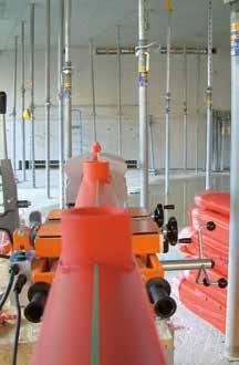
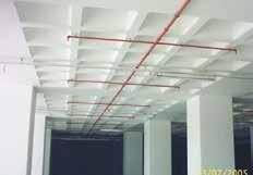
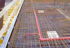
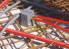
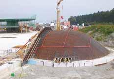
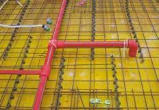
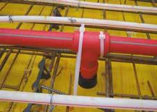
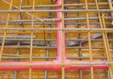
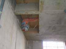
51 LAYING IN THE CONCRETE Upper part sprinkler outlet 4 3 Brass plug Base part sprinkler outlet 2 Picture 1 1 LAYING OF AQUATHERM RE PIPE IN THE CONCRETE Part 1: Connecting of pipe work to the aquatherm re pipe sprinkler outlet The connection is escribe in picture 1 as follows: The base part of the sprinkler outlet (1) is screwe with 4 screws on the shuttering. etaile information regaring the ifferent imensions of the sprinkler outlet please take from tables on pages 21 an 22! Colour of plastic sleeve may iffer. Brass plug (2), upper part of the sprinkler outlet (3) an aquatherm re pipe connection piece (4) are connecte to each other an plugge onto the base part of the sprinkler outlet (1), so that part 3 is flush with the shuttering. Part 2, 3 an 4 are bolte together an plugge on part 1, so that part 3 is flush with the casing. The O-ring on part 2 (plug) must always be clean an grease with mounting grease. After the repeate use the O-ring shoul be replace. This applies to the item-no.:
, the base part of the sprinkler outlet (1) is pulle out of the upper part of the sprinkler outlet (3).")
 must be pulle out of the concrete easily with the aquatherm re pipe extraction tool (Art. no. 50290).")
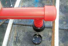
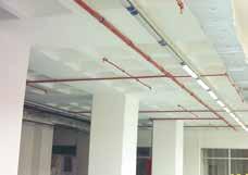
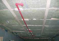
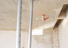
52 LAYING IN THE CONCRETE LAYING OF AQUATHERM RE PIPE-PIPES IN THE CONCRETE Picture 2 LAYING OF AQUATHERM RE PIPE IN THE CONCRETE The aquatherm re pipe sprinkler connection is finishe (picture 2). Picture 3 When removing the shuttering (after pouring of the concrete), the base part of the sprinkler outlet (1) is pulle out of the upper part of the sprinkler outlet (3). The brass plug (2) is unscrewe from the aquatherm re pipe connection piece (part 4). Now, the upper part of sprinkler outlet (3) must be pulle out of the concrete easily with the aquatherm re pipe extraction tool (Art. no ). The sprinkler connection (picture 3) can be complete very easily. The, acc. to CEA 4001, require istance from the sprinkler hea to the complete ceiling, can be accomplishe with the compensating fitting from the sprinkler connection threa up to the aquatherm re pipe connecting piece (see rawing page 56). 52

53 LAYING IN THE CONCRETE LAYING OF AQUATHERM RE PIPE IN THE CONCRETE Sprinkler outlet consists of the base part, upper part an plug. Vormontage pre-assembly sprinkler outlet Sprinkler-Anschlussos e Visible sprinkler For the istance from the eflector to the ceiling, refer to the CEA You will fin compensating joints on page 23. complete-assembly Fertigmontage For further information on the sprinkler outlets please see the tables on pages 21 an 22. Covere sprinkler complete-assembly Fertigmontage Ausgleichsanschluss Stanar extension compensating joints a a = gen. CEA 4001 It has to be ensure that the aquatherm re pipe is covere above an below by a minimum 60 mm layer concrete layer. 60 mm 60 mm 53
 are vali.")

 If the sprinkler connection protrues obliquely from the concrete surface, it is possible to align this with the balancing connection.")
 This requires a special ajusting tool. It is important to ensure that the bening raius is not more than 15. The bearing surface of the female threa serves as a reference point on the surface.")
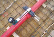
54 LAYING IN THE CONCRETE aquatherm re Pipe system mae of polypropylene for sprinklers COMPENSATING JOINT AN AJUSTING TOOL Compensation joint for use with aquatherm re pipe, pipe system mae of plastic, VS approval number: G The specifications of the technical catalogue aquatherm re pipe an the VS CEA 4001 (Guielines for sprinkler systems planning an installation) are vali. Application: Correction of non-aligne sprinkler connections in concrete ceilings, maximum correction angle 15 an for compensation of the connection threa to the sprinkler threa (maximum 3 cm) in concrete ceilings, maximum operating pressure 18 bar. Important instructions: The compensating joint may only be bent once multiple reverse bening is not permitte Maximum tightening torque for sprinkler = 29 Nm Only for the irect connection of the sprinkler 1 2 compensating joint < ) If the sprinkler connection protrues obliquely from the concrete surface, it is possible to align this with the balancing connection. The balancing connection is installe with the provie hexagon in the sprinkler connection threa. A common sealing metho for the preparation of waterproof threae connections is to be use. 2) This requires a special ajusting tool. It is important to ensure that the bening raius is not more than 15. The bearing surface of the female threa serves as a reference point on the surface. 3 4 ajusting tool 3) The ajusting tool is screwe into the balancing connection with the appropriate aapter. 4) With gentle pressure by han, the compensating joint is pushe into its position until the plate of the ajusting tool fits proper against the concrete surface. 54


55 LAYING IN THE CONCRETE aquatherm re Pipe system mae of polypropylene for sprinklers COMPENSATING JOINT AN AJUSTING TOOL 5 6 < 15 stop 0 5) To check the perpenicularity, there is a level at the en of the hanle. The stop limits the bening raius to ) When the sprinkler is installe, the sprinkler connection is subject to the pressure test as usual an teste for leaks. The maximum operating pressure is 18 bar. Ajusting tool for balancing connection page 34 Art. no Compensating joint page 23 Art. no Art. no Art. no Art. no
56 LAYING IN THE CONCRETE LAYING OF AQUATHERM RE PIPE IN THE CONCRETE concrete aquatherm re pipe outlet 1 1 / 4 ", 1 1 / 2 " an 2" aquatherm re pipe sprinkler outlet for covere sprinkler 1 / 2 ", 3 / 4 " an 1" ATTENTION All upper parts of sprinkler outlet must be pulle out of the concrete with the aquatherm re pipe extraction tool (Art. no ). 3 aquatherm re pipe sprinkler outlet for visible sprinkler 1 / 2 ", 3 / 4 " an 1" 4 aquatherm re pipe to steel pipe aapter 56
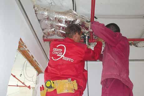
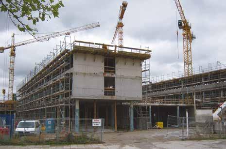
57 LAYING IN THE CONCRETE LAYING OF AQUATHERM RE PIPE IN THE CONCRETE escription of the installation in prefabricate concrete ceiling (Filigree ceiling) Introuction: Because precast concrete proucts are irectly shuttere an processe at factory, there remain only some working steps at site. A slab formwork on site is not require. The rapi laying an on-site-installation saves time an costs. ue to the very smooth soffit by the steel formwork table, a plastering is not necessary. Base part of sprinkler outlet Art. no for visible sprinklers. Attachment by magnet. If an installation system is mounte on the steel formwork, this must work precisely, safely an quickly. The sprinkler outlet of the sprinkler pipe system aquatherm re pipe can be easily mounte on steel formwork. The entire component is assemble in avance by an installation company an elivere to the concrete plant. In the concrete plant, the sprinkler outlets are measure on the steel formwork an mounte. Assembly: Base part of sprinkler outlet Art. no for conceale sprinklers. Attachment with hot-melt ahesive. The base part of the sprinkler outlet is fixe with a magnet (min. holing force 23 kg), or with a hot-melt ahesive (temperature 100 C) to the steel formwork with reinforcement an also keeps the position uring vibrations. The length of the pipe connecting piece has to be imensione so that it is protecte by the projecting reinforcement on the transport to the site. The pipe connecting piece is protecte by a protective cap an ahesive tape, thereby preventing the penetration of concrete into the interior of the pipe uring filling of the mol. The upper part of the sprinkler outlet with pipe connection is attache to the base part of the sprinkler outlet. 1. Type of connection: visible sprinkler 2. Type of connection: conceale sprinkler 57


58 LAYING IN THE CONCRETE PRÜFUNG LAYING OF AQUATHERM RE PIPE IN THE CONCRETE escription of the installation in prefabricate concrete ceiling (Filigree ceiling) Assembly: The mol is fille with concrete an vibrate simultaneously. After shaking the concrete surface is roughene. The component is to ry in a rying chamber. After rying, the ceiling component is transporte to the site an assemble. An installation company can now connect the sprinkler connections with each other an connect them to the supply pipe. Thus, this metho of prefabrication allows shorter construction perios an larger areas. This results in a cost reuction on the one han an some more flexibility all in all an increase of economy. 58
 an to unerpin (picture 2). The pipe sections must be fixe every 1.")
. The entering of the pipes uring the concreting process must be avoie.")
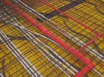
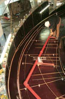
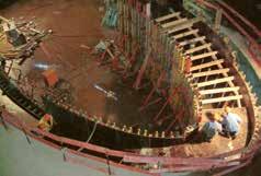
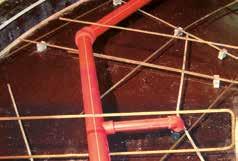
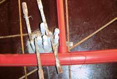
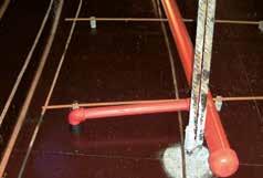
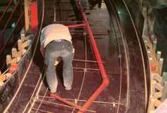
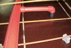
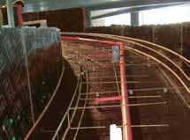
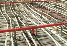
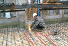
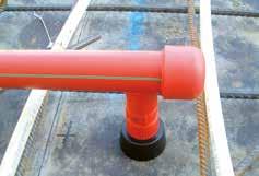
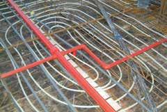
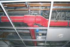
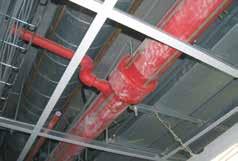
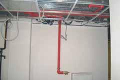
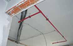
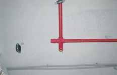
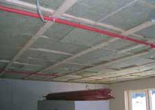
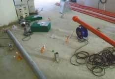
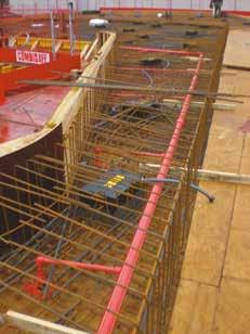
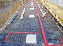
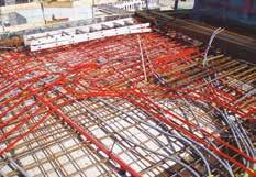
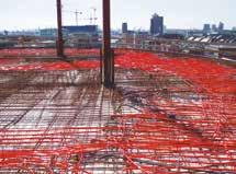
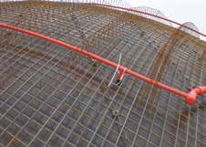
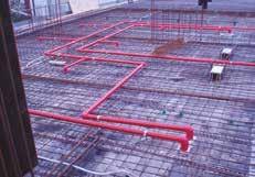
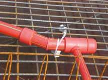
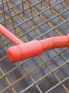
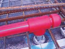
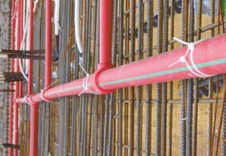
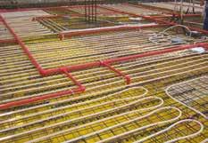
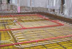
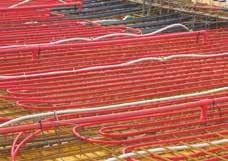
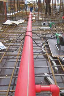
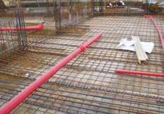
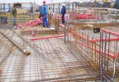
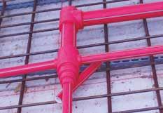
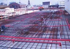
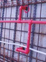
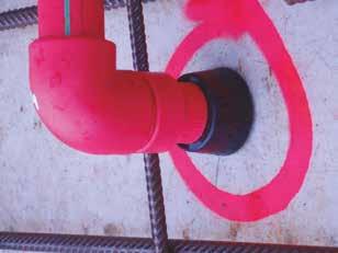
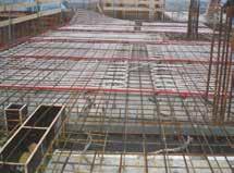
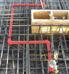
59 LAYING IN THE CONCRETE 1 2 LAYING OF AQUATHERM RE PIPE IN THE CONCRETE Part 2: Pressure test of pipe work installation as strength test an leak test Please refer to the information on page Part 3: What must be consiere uring the concreting process? All sprinkler connections have to be locke with cable clips (picture 1) an to unerpin (picture 2). The pipe sections must be fixe every 1.5 to 2 m in a way (using pipe hangers or lacing cor) to avoi sagging or bowing uring the concreting process. It is important, that the pipe work is completely embee without any hollow spaces (cavities). The entering of the pipes uring the concreting process must be avoie. The compacting of the concrete with concrete vibrators in the pipe area shoul be carrie out carefully. Impacts, especially at low temperatures (below +5 C) must be avoie. Open pipes an connections must be close before the concreting. Pipes an sprinkler connections must be fitte with suitable material (see fig. 1) in orer to avoi bening. The sprinkler connection (sprinkler outlet) must be in the correct position. If necessary, this shoul be aligne an re-fastene before concreting. 59

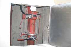
60 LAYING IN THE CONCRETE LAYING OF AQUATHERM RE PIPE IN THE CONCRETE Part 4: Access to connection of the pipe work in concrete Option 1: The pipe work in the concrete shoul be connecte to the supply pipe, that the connection can be accesse in case of amage. This may accomplishe as follows: Before applying the concrete on the ceiling, a form work (casing) shoul be constructe aroun the connection (allow enough space for installation work). The connection is embee in san or similar fill of F90-quality in the form work. The ceiling can be fille with concrete now. After striking the ceiling, the connection can be lai open an is now accessible. The subsequent sealing of the cavity in the ceiling can be mae with elements of F90-quality. The access must be visible at all times (inicate on the rawing or by marking the ceiling). Option 2: Before casting the connection can be packe in a Rockwool-fire protection panel Conlit 150 U (allow enough space for installation work). This panel has the following features: light, water-repellent, pressure-resistant, self-supporting rockwool panel covere with glass gri rawing accoring to options 1 an 2 riser opening for inspection pipe Fiels of application: fire protection covering for steel construction F30 A-F180-A, Increase of fire resistance class of concrete coverings. Not flammable A2 acc. to IN 4102, Part 1. Melting point > 1000 C. After shuttering of the ceilings, the fire protection panel Conlit 150 U can remain in the complete ceiling an can be ajuste to the structure of the concrete ceiling by plastering. The access shall be visible, as in option 1, at all time. rawing accoring to options 1 an 2 60
61 LAYING IN THE CONCRETE LAYING OF AQUATHERM RE PIPE IN THE CONCRETE amage pipe work in concrete, e.g. by rilling work amage pipe work can be repaire by fusion weling (see aquatherm re pipe sprinkler system, Part B). The aquatherm re pipe system can also be repaire using the pipe repair stick (see aquatherm re pipe sprinkler system, Part F). Part 5: Briging of expansion joints The expansion or aquatherm re pipe pipes epens on the temperature of the pipe material. Col water supplies cause harly any expansion for a normal assembly nor o normal outsie temperatures. The expansion nee not to be consiere when laying aquatherm re pipe in the concrete. Rising pressures- an tensile stresses are not critical, as they are absorbe by the material. However, if it is necessary to brige the expansion joints, the aquatherm re pipes must be equippe with an approx. 25 cm protection pipe at both ens of the joint. A confirmation of the responsible architect resp. structural esigner must certify that no lengthwise movements in the expansion joints can be expecte. Briging of builing joints is not permitte. The coefficient of expansion of aquatherm re pipe pipes is mm/mk The coefficient of expansion of concrete is mm/mk. Part 7: Pressurizing in the aquatherm re pipe supply uring the concreting process uring the concreting process the pipe must be pressurize with the amissible operating pressure, so that a amage point is visible at once. After the pressure test the amissible operating pressure is kept by shut off of the respective pipe. The applie measuring evices must grant a correct reaing of pressure changes of 0.1 bar. The pressure measuring evice shall be installe at the eepest point of the pipe system. Part 8: Influence of the concrete on the applie compouns The aquatherm re pipe pipe system contains all require compouns for a complete system installation. Mixe installation with non-system an/or non-material compouns are not require. All material is resistant to corrosion. The threas of the aquatherm re pipe sprinkler connection fittings are mae from brass (CuZn36Pb2As). Experiences with this material confirm that the alloy has an excellent resistance against concrete. The general builing regulations have to be complie with locally. If special chemical aitives (retarer etc.) are applie, information from the manufacturer of the concrete shoul be gathere; refer to aquatherm for suitablity. Part 6: Potential equalizing The VE 0190 Part 410 an 540 requires a potential equalizing between all kins of earth conuctors an the existing conuctible potable an waste water supplies an heating pipes. As aquatherm re pipe is not a conuctible pipe system, it cannot be use for potential equalizing an thus nees no earth wiring. The potential equalizing is mae accoring to VE-stanar from the builing parts, which have to be earth wire, irectly to the potential equalizing rail to the planne position. The constructor or site manager must avise the client or his representative, that an approve electrician must check, if the aquatherm re pipe installation oes not affect the existing electrical protection an earth wiring measurements (VOB Part C, generaltechnical conitions of contract ATV). 61
62 TEST LEAKAGE TEST All sprinkler pipelines shall be subjecte to a hyraulical pressure test with a test-pressure of 10 bar. The material properties of the aquatherm re pipes result in an expansion of the pipes uring the pressure test. This affects the test result. ue to the thermal expansion coefficients of the aquatherm re pipes the results are influence aitionally. The temperature ifferences between the pipe an the test meium lea to changes in pressure. Hereby a temperature change of 10 K correspons to a pressure ifference of 0,5 up to 1 bar. Therefore, pressure testing of the aquatherm re pipe systems shoul be mae with a constant temperature of the test meium. The hyraulic pressure test requires a preliminary, principal an final test. Measuring of the test pressures Measuring has to be one with a manometer allowing a perfect reaing of a pressure change of 0.1 bar. The manometer has to be place at the eepest point of the installation. Test recor A recor of the hyraulic pressure test has to be prepare an signe by the client an contractor stating place an ate (see pages 64/65). In the preliminary test a pressure of 18 bar is applie 3 x 5 minutes for the expansion/release of the pipes. Between the cycles the pipe system must be epressurize. Immeiately after the preliminary test the principal test shoul be performe. The test uration is 15 min. Here, the test pressure (10 bar) may not fall more than 0,5 bar. After completion of the preliminary an principle test finally the final test must be performe. The test uration is 60 minutes. Here, the test pressure rea after the principle test may not fall more than 0,5 bar. 62
63 TEST LEAKAGE TEST/PRESURE IAGRAM PRELIMINARY TEST Working pressure 18 bar 0 bar 5 min. 5 min. 5 min. PRINCIPAL- AN FINAL TEST Working pressure 10 bar p max. = 0,5 bar p max. = 0,5 bar Principal test Final test 15 min. 75 min. 63
64 TEST TEST RECOR AQUATHERM RE PIPE SYSTEM INSTALLATION Test recor aquatherm system installation Place: Object: Note before the test: 3x 5 minutes system pressure of 18 bar for expansion/release of the pipes are require. Preliminary test The pipe system must be unpressurize between each cycle. 18 bar 5 min. realize: yes no 18 bar 5 min. realize: yes no 18 bar 5 min. realize: yes no Principal test Test pressure: 10 bar Pressure ecline after 15 min.: bar max. 0,5 bar Final test (irectly after the principal test, without changing the pressure) Result principal test: bar Pressure ecline after 60 min.: bar max. 0,5 bar Notes: Place: ate: Stamp/Signature 64
65 TEST escription of installation Place: Object: Pipe length: Ø 20 mm Ø 25 mm Ø 32 mm Ø 40 mm Ø 50 mm Ø 63 mm Ø 75 mm Ø 90 mm Ø 125 mm Ø 160 mm m m m m m m m m m m Start of test: En of test: Testperio: Test meium: water water/glycol Client: Contractor: Place: ate: Stamp/Signature 65
66 TEST AQUATHERM RE PIPE SYSTEM Enquiry for the chemical resistance Enquiry for the chemical resistance of the aquatherm re pipe pipe system aquatherm GmbH Technical epartment Biggen Attenorn Phone: Fax: Internet: Installer: Fiel of application: Installer Flui transporte: Company Operating temperature C Street Working pressure bar City Service life h / Phone Concentration % Fax Builing project: Ambient meium: Ambient temperature C Ambient pressure bar Builing project: Street City Place, ate / Signature not ata sheets enclose enclose Flui transporte Ambient meium 66


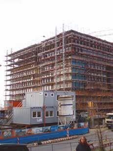
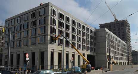
67 REFERENCES REFERENCES Office Builing Römischer Hof Berlin, Germany Spiegel Builing Hamburg, Germany 67

68 REFERENCES REFERENCES The European Patent Office Munich, Germany 68


69 REFERENCES REFERENCES Public services munich, technology center Munich, Germany 69
70 REFERENCES REFERENCES HYPO-Center Innsbruck, Austria Foto: Hypo Tirol Bank AG 70
71 REFERENCES REFERENCES Raschal-Centre for chilren surgery an traumatology Moscow, Russia Foto: Hypo Tirol Bank AG 71

72 REFERENCES REFERENCES Shopping Centre Moscow, Russia Office Builing Moscow, Russia 72
73 REFERENCES REFERENCES Hotel Sween CARPET WAREHOUSE Turkey 73


74 REFERENCES REFERENCES Panion Vista, luxury apartments Cologne, Germany 74


75 REFERENCES REFERENCES AachenMünchener Insurance Aachen, Germany Feeral Archives Berlin, Germany Unionsbräu ortmun, Germany 75

76 REFERENCES REFERENCES Coffee Plaza Hamburg Hafencity, Germany Upper West Berlin, Germany 76

77 REFERENCES REFERENCES ornier Museum Frierichshafen, Germany Metropolis Hamburg, Germany 77

78 REFERENCES REFERENCES Hans Sachs Builing Gelsenkirchen, Germany 78

79 REFERENCES REFERENCES Central office HI-Gerling Insurance Hannover, Germany 79


80 REFERENCES REFERENCES Crystalbuiling Hamburg fish market, Germany 80


81 REFERENCES REFERENCES Office builing Röingsmarkt Hamburg, Germany Überseequartier Hamburg, Germany 81

82 REFERENCES REFERENCES Kö-Bogen, shopping an event center üsselorf, Germany 82


83 REFERENCES REFERENCES GEWA Tower Fellbach, Germany aquatherm factory Attenorn, Germany Assembly precast concrete ceiling Prefabrication concrete wall 83


84 REFERENCES REFERENCES Tanzene Türme Hamburg, Germany Schwabinger Tor Munich, Germany 84
General Safety Notes for Chain Slings (Grade 50/60) Last revised: January 2018
 Last revised: January 2018") General Safety Notes for Chain Slings (Grae 50/60) Last revise: January 2018 Ketten Wäler GmbH Chain Technology Gewerbegebiet 5 83093 Ba Enorf, Germany Fon +49 (0)80 53-20 29-10 Fax +49 (0)80 53-20 29-31
General Safety Notes for Chain Slings (Grae 50/60) Last revise: January 2018 Ketten Wäler GmbH Chain Technology Gewerbegebiet 5 83093 Ba Enorf, Germany Fon +49 (0)80 53-20 29-10 Fax +49 (0)80 53-20 29-31
STAD BALANCING VALVES
 BAANCING BAANCING VAVES BAANCING VAVE The STAD balancing valve elivers accurate hyronic perfomance in an impressive range of applications. Ieally suite for use on the seconary sie in heating an cooling
Products no longer available
 Technical ata sheet R7..R Open-close ball valves, 3-way, with flange PN 6 for open an close col an warm water systems for switching functions on the water sie an 2-point controls in air-hanling an heating
Products no longer available
 Technical ata sheet R7..R haracterize control valves, 3-way, with flange PN 6 for open an close col an warm water systems for moulating control on the water sie of air-hanling an heating systems air bubble-tight
RB 4700 Commercial & Industrial Regulator
 RB 4700 Commercial & Inustrial Regulator The RB 4700 regulator is esigne for use in inustrial an istribution applications such as istrict station an heating plants, an for inustrial customers. DESCRIPTION
For latest prices and delivery to your door visit MyTub Ltd
 Technical ata sheet A6H / A6S Shut-off valves with clips, PN 6 / PN / PN 6, with manual overrie in open an close col an warm water systems for switching heating an cooling machines on an off Overview of
The valves are used in combination with AMV(E) 130/140, AMV(E) 130H/140H and AMV(E) 13 SU actuators. DN k VS
 130/140, AMV(E) 130H/140H and AMV(E) 13 SU actuators. DN k VS") Description VZ 2 VZ 3 VZ 4 VZ valves provie a high quality, cost effective solution for the control of hot an/or chille water for fan coil units, small reheaters, an recoolers in temperature control systems.
Description VZ 2 VZ 3 VZ 4 VZ valves provie a high quality, cost effective solution for the control of hot an/or chille water for fan coil units, small reheaters, an recoolers in temperature control systems.
Type overview. Technical data. Safety notes
 Technical ata sheet hange-over ball valve, 3-way, Flange, PN 6 For close col an warm water systems For switching functions on the water sie an 2-point controls in air hanling units an heating systems ir
PROTECTIVE HOSES. HYDRA Stripwound hoses for optoelectronics, laser procedures, medical technology or the pharmaceutical and food industry.
 PROTECTIVE HOSES HYRA Stripwoun hoses for optoelectronics, laser proceures, meical technology or the pharmaceutical an foo inustry. Witzenmann-Speck GmbH Werner-Siemens-Str. 2 29 Kieselbronn, Germany Phone
Systems and Components
 new LINEAR SYSTEMS AND COMPONENTS SELF-ALIGNING LINEAR BEARINGS & PILLOW BLOCKS TM LINEAR SYSTEMS AND COMPONENTS TECHNICAL INTRODUCTION 29-228 PRECISION HARDENED AND GROUND SHAFTING 240-243 Linear Ball
AS13 1F-M3 AS13 1F-M5 AS23 1F-01 AS23 1F-02
 Spee Controller with One-touch Fittings Series Elbow Style, Universal Style Minimizes installation time an cost Reuces the mounting height an enables compact machinery esign. Effective area is larger than
Instruction manual. for. high purity gas pigtails 200 bar / 300 bar
 Instruction manual for high purity gas pigtails 200 bar / 300 bar Contents Contents... 2 1. Preface... 3 1.1 Overview... 3 1.2 General... 3 1.3 Intended use... 4 1.4 Personnel requirements... 4 2. For
Process Name Material Handling/MSD Prevention Program
 CNM WAY PROCESS CNM Process Name Material Hanling/MSD Prevention Program (04/10/2018 Revision) Overview of Material Hanling/MSD Prevention Program Purpose: To provie a safe an healthy working environment
The valves are used in combination with AMV(E) 130/140, AMV(E) 130H/140H and AMV(E) 13 SU actuators. DN k VS
 130/140, AMV(E) 130H/140H and AMV(E) 13 SU actuators. DN k VS") Description VZ 2 VZ 3 VZ 4 VZ valves provie a high quality, cost effective solution for the control of hot an/or chille water for fan coil units, small reheaters, an recoolers in temperature control systems.
Description VZ 2 VZ 3 VZ 4 VZ valves provie a high quality, cost effective solution for the control of hot an/or chille water for fan coil units, small reheaters, an recoolers in temperature control systems.
aquatherm state of the pipe
 2013 PRODUCT CATALOGUE 2013 aquatherm state of the pipe All prices are for piece, m, m², kg or set. Recommended retail price of the manufacturer. Our sales and delivery conditions (January 2012) and the
aquatherm green aquatherm blue aquatherm lilac aquatherm state of the pipe Pipe system made of polypropylene for potable water supply
 Edition: 07.2014 aquatherm green Pipe system made of polypropylene for potable water supply aquatherm blue Pipe system made of polypropylene for chilled, hot fluid and various industrial applications aquatherm
APG001. Application Guide for Gas. T: F: E:
 APG001 Application Guide for Gas T: 01480 442600 F: 01480 458829 E: customerservice@gpsuk.com www.gpsuk.com Application Guide for Gas Introduction 3-4 Range Overview 5-6 PE80 Yellow Pipe 7-9 Excel Yellow
Sur face options bright finish anodic clean electropolished. Outer surface: Ra 0.80 µm (32 µin)
") Material imensions Technical terms of elivery Tubes Length Fittings Tolerances Ens Wele or seamless austenitic stainless steel tubes, epening on outer iameter (see imensions). 1.4435/BN2/TP316L, -Ferrite
Material imensions Technical terms of elivery Tubes Length Fittings Tolerances Ens Wele or seamless austenitic stainless steel tubes, epening on outer iameter (see imensions). 1.4435/BN2/TP316L, -Ferrite
Type BBS-03, BBS-05, BBS-06, BBS-25
 Type BBS-03, BBS-05, BBS-06, BBS-25 Sterile connection elements Sterile Verbindungselemente Raccords union stériles Operating Instructions Bedienungsanleitung Manuel d utilisation 1. THE OPERATING INSTRUCTIONS
LESER Global Standard Tightness Test. Content
 LESER Global Stanar Page 1/29 Content 1 Purpose... 1 2 Scope... 1 3 References... 1 4 Introuction... 2 5 Test Proceures at LESER... 3 6 Test Equipment at LESER... 3 7 Seat tightness test proceure, Test
Seamless or welded stainless steel tube, depending on outer diameter (see dimensions). TP316L / /
. TP316L / /") Material imensions Technical terms of elivery Tubes ength Fittings Tolerances W el ens Seamless or wele stainless steel tube, epening on outer iameter (see imensions). TP316 / 1.4404 / 1.4435 Stock imensions:
Material imensions Technical terms of elivery Tubes ength Fittings Tolerances W el ens Seamless or wele stainless steel tube, epening on outer iameter (see imensions). TP316 / 1.4404 / 1.4435 Stock imensions:
Laboratory Mortar Mixer (Testing)
") TomTom-Tools GmbH Zelgli 20 8905 Arni info@tomtom-tools.com Switzerland www.tomtom-tools.com User Manual Version February 22, 2015 Laboratory Mortar Mixer (Testing) 1 Introduction The Laboratory Mortar
TomTom-Tools GmbH Zelgli 20 8905 Arni info@tomtom-tools.com Switzerland www.tomtom-tools.com User Manual Version February 22, 2015 Laboratory Mortar Mixer (Testing) 1 Introduction The Laboratory Mortar
better measurement Simply a question of SCHMIDT Flow Sensor SS The cost-effective alternative in pressurised systems up to 10 bars.
 Simply a question of better measurement SCHMIDT Flow Sensor SS 20.261 The cost-effective alternative in pressurised systems up to 10 bars. Compressed air technology Industrial processes A cost analysis
LOK-BOLT AS. Mechanical Anchors GENERAL INFORMATION SECTION CONTENTS. Sleeve Anchor
 General Information Mechanical s GENERAL INFORMATION LOK-BOLT AS Sleeve PRODUCT DESCRIPTION The Lok-Bolt AS is an all-steel pre-assemble single unit sleeve anchor which is esigne for use in concrete or
Instruction Manual Contact Pressure Vacuum Gauge
 MS10 Instruction Manual Contact Pressure Vacuum Gauge Table of Contents 1. Safety Instructions 2. Intended Applications 3. Product Description and Functions 4. Installation 5. Commissioning 6. Maintenance
Engineering Data Sheet
 Page 1 of 6 CE MARKING AND THE PRESSURE EQUIPMENT DIRECTIVE 97/23/EC Valves must be installed into a well designed system and it is recommended that the system be inspected in accordance with the appropriate
REFER TO AQUATHERM TECHNICAL BULLETIN A-AQTTB FOR ADDITIONAL INFORMATION AND SAFETY PRECAUTIONS
 Aquatherm Standard Pressure Testing Procedure Aquatherm offers an extensive warranty to protect against damages caused by failure from manufacturer s defect. Aquatherm requires that all installations be
Pressure Relief Valve DHV 718
 Advantages frictionless components low maintenance low pressure increase up to fully opened valve constant low vibration controlling hermetically sealed by diaphragm for oscillating pumps for viscous media
Instruction Manual. CG16K Barometrically Compensated Capsule Dial Gauge. CG16K Capsule Dial Gauge, 0 to 25 mbar
 Instruction Manual D356-10-880 Issue G Original CG16K Barometrically Compensated Capsule Dial Gauge Description CG16K Capsule Dial Gauge, 0 to 1040 mbar CG16K Capsule Dial Gauge, 0 to 125 mbar CG16K Capsule
PURA. Pure Gas Dewpoint Transmitter. Users Guide
 PURA Pure Gas Dewpoint Transmitter Users Guide Issue January 2003 Page 2 Table of Contents SECTION PAGE 1 Product Overview 3 2 Preparation 3 3 Installation 3 3.1 PURA Premium & OEM Dewpoint Transmitter
Pilot Check Valve: Metal Body Type
 INFORMATION Pilot Check Valve: Metal Body Type The use of a metal body improves strength and environmental resistance. Temporary intermediate stops are possible. *1 *1 Precise intermediate stops are not
Instructions for Use. Plug connection for medical gas and vacuum acc. to DIN / 2004 DIN EN ISO
 Instructions for Use Plug connection for medical gas and vacuum acc. to DIN 13260-2 / 2004 DIN EN ISO 9170-1 Table of Contents Page 1. MANUFACTURER S DATA... 3 2. INTRODUCTION... 4 3. APPLICATION... 5
Continental Industries TRANSITION FITTINGS or FAX Visit
 Continental Industries TRANSITION FITTINGS 1-800-558-1373 or FAX 1-800-788-1668 Visit www.conind.com ABOUT US Our Company Continental Industries, headquartered in Tulsa, Oklahoma, was formed in 1958 and
Series AS-FPQ/AS-FPG. Speed Controller with One-touch Fitting for Clean Room. Speed controllers for clean room use
 CAT.ES20-19 A Speed Controller with One-touch Fitting for Clean Room Series AS-FPQ/AS-FPG Series AS-FPG Series AS-FPQ Speed controllers for clean room use AS-FPQ: Brass (electroless nickel plated) and
Mounting and Operating Instructions EB EN. Type Supply Pressure Regulator. with increased air capacity
 Type 4708-45 Supply Pressure Regulator with increased air capacity Translation of original instructions Mounting and Operating Instructions EB 8546-1 EN Edition March 2016 Note on these mounting and operating
Underground irrigation
 Prograers Turbines and Pop-ups Solenoid valves ittings Accessories and Hoses 70 Irrigation located in set areas, and the only time that you need to invest into it, is the time it takes to set it up, then
Mounting and operating instructions EB 2530 EN. Self-operated Pressure Regulator. Pressure Reducing Valve Type M 44-2
 Self-operated Pressure Regulator Pressure Reducing Valve Type M 44-2 Type M 44-2, connection G 1 4, K VS = 0.15 Type M 44-2, connection G 1, K VS = 6 Fig. 1 Type M 44-2 Pressure Reducing Valve Mounting
RS(H)10,15 USER MANUAL. Read the complete manual before installing and using the regulator.
10,15 USER MANUAL. Read the complete manual before installing and using the regulator.") RS(H)10,15 USER MANUAL Read the complete manual before installing and using the regulator. WARNING INCORRECT OR IMPROPER USE OF THIS PRODUCT CAN CAUSE SERIOUS PERSONAL INJURY AND PROPERTY DAMAGE. Due to
RS(H)10,15 USER MANUAL Read the complete manual before installing and using the regulator. WARNING INCORRECT OR IMPROPER USE OF THIS PRODUCT CAN CAUSE SERIOUS PERSONAL INJURY AND PROPERTY DAMAGE. Due to
BERMAD Waterworks. Combination Air Valve. Air Valves Series. Typical Applications. Features & Benefits. Additional Features.
 BERMA Waterworks Combination Air Valve Model C7 BERMA C7 is a high quality combination air valve for a variety of water networks and operating conditions. It evacuates air during pipeline filling, allows
Operating Instructions in compliance with Pressure Equipment Directive 2014/68/EU. AWA Change-over Valve
 Operating Instructions in compliance with Pressure Equipment Directive 2014/68/EU AWA Change-over Valve Please read these operating instructions carefully to ensure a safe operation and keep the same for
Flexible & Intelligent
 Flexible & Intelligent The flexible copper tube cuprotherm CTX tubes are copper tubes with a firmly adherent coating. Due to their structure they can be easily processed and are characterized by a flexibility
Push-in fittings CRQS, stainless steel
 Features Application Effortless selection of the right fitting. Festo offers a secure solution for every connection. The convenient push-in fitting system includes well over 1000 types of standard and
Cautions : 1. Clogging of the element raises resistance to exhaust, thus lowering the
 The Silencer, connected to the exhaust port of a device, suppresses the exhaust noise. The Silencer displays an excellent noise suppression effect. Three types are available for your selection. The element
PN LINE. Technical remarks PN 11 PN 13 PN 14 PN 15 PN 17 PN 18 PN 20 PN 23 PN 25 PN 26 PN 27 PN 28 PN 29 PN 37 PN 38 PN 39 PN 40 PN 43 PN 10 8_9 10_12
 PN LINE PN 11 PN 13 PN 14 PN 15 PN 17 PN 18 PN 20 PN 23 PN 25 PN 26 PN 27 PN 28 PN 29 PN 37 PN 38 PN 39 PN 40 PN 43 PN 10 Technical remarks PN 11 PN 13 PN 14 PN 15 PN 17 PN 18 PN 20 PN 23 PN 25 PN 26 PN
Pipe threads for tubes and fittings where pressure-tight joints are not made on the threads. (requires PTFE sealing tape or liquid sealant).
.") Fittings for CO 2 Pipe Threads Pipe thread references quoted in this catalogue conform with the requirements specified in the latest issue and amendments of the following ISO Standards: ISO 7-1 (BS21)
Fittings for CO 2 Pipe Threads Pipe thread references quoted in this catalogue conform with the requirements specified in the latest issue and amendments of the following ISO Standards: ISO 7-1 (BS21)
MUELLER. Mega-Lite Drilling Machine. Reliable Connections. table of contents PAGE. Equipment 2. Operating Instructions 3-4. Parts Information 5
 operating Instructions manual MUELLER Mega-Lite Drilling Machine table of contents PAGE Equipment 2 Operating Instructions 3-4 Parts Information 5 Travel Charts 6-11! WARNING: 1. Read and follow instructions
PSI Mechanical Couplings
 Pipeline Accessories PSI Mechanical Couplings Systems Permasert and PermaLock Permasert and Permalock are Elster Perfection registered trade marks General Information Technical Data Installation Instructions
Ball Valves for Heating and District Heating. Date 1
 Ball Valves for Heating and District Heating Date 1 Underground Ball Valves DN 20 DN 600, PN25 Underground valves are installed in pre insulated pipe systems, transporting hot water from production to
TECHNICAL DATA. Q = C v P S
 January 6, 2012 Preaction 348a 1. Description Viking supervised Surefire Preaction Systems utilize the Viking G-6000P Valve. The small profile, lightweight, pilot operated Viking G-6000P Valve comes complete
Plummer Block Housings
 Plummer Block Housings TECHNICAL INFORMATION Feature The majority of SLB Plummer Block Housing is made of Gray Cast Iron and is of the models of 'SN', 'SNU' and 'SAF'. Its basic size conforms with 'ISO'
Type Pressure Regulator. for increased air capacity. Fig. 1: Type Pressure Regulator. Mounting and Operating Instructions EB EN
 Type 4708-45 Pressure Regulator for increased air capacity Fig. 1: Type 4708-45 Pressure Regulator Mounting and Operating Instructions EB 8546-1 EN Edition March 2010 Definition of the signal words used
Flow controller Type ED/CCB311 Instruction manual
 Flow measurement Flow controller Type ED/CCB311 1. GENERAL DESCRIPTION page 4 2. DETAILED DESCRIPTION page 4 3. PIPE - EXPLOITATION page 5 4. PREVENTIVE MAINTENANCE page 5 5. REPLACEMENT OF THE CONTACT
Operating instructions - Translation of the original -
 Operating instructions - Translation of the original - 5093 xxx 000-xxx Check valve DN25 - DN100 EPDM O-Ring-design Intermediate flanged with welding ends 27.1.12 KIESELMANN GmbH Paul-Kieselmann-Str.4-10
Code AWC20HP Air Compressor
 Code 951816 AWC20HP Air Compressor Index of Contents Index of Contents 02 Declaration of Conformity 02 What s Included 03 Safety Precautions 03 Specifications (AWC20HP Air Compressor) 04 Assembly Instructions
THE PROCESS OF JOINT INTEGRITY
 BOLTED JOINTS A.333 THE PROCESS OF JOINT INTEGRITY To assist in managing a process, ask yourself the following questions: why, what, who, and how? Why do we need a Flange Joint Integrity program? This
CONNECTION > Super-rapid fittings Series 6000 GENERAL DATA. Fitting with connecting tube. Sprint
 Super-rapid fittings for plastic tubes Series 6000 Sprint Tube external diameters: 3,, 5, 6, 8, 10, 12, 1, 16 mm Fittings threads: metric (M3, M5, M6, M7), BSP (G1/8, G1/, G3/8, G1/2, G3/), BSPT (R1/8,
CFSW. Hinges with built-in safety multiple switch
 CFSW. Hinges with built-in safety multiple switch ELESA Original design Elesa Standards Main dimensions Fitting Weight Code Description L B f ±0.2 f 1 ±0.2 H h 1 h 2 d 3 d 4 C [Nm]# g 426601 CFSW.110-6-2NO+2NC-C-A
Coiling Tube with Twist-Proof Fitting
 http://www.pisco.co.jp FITTING CONTROLLER VALVE TUBE MAKE-TO-ORDER PRODUCTS Push-In Fitting Type Anti-Twisting Coiling Tube for Air Tool Coiling Tube with Twist-Proof Fitting 306 Avoid Twisted Tube Problem
(1) Type (2) Thread size (T) (3) Wrench size specification : inch spec. (NPT, UNF) : mm spec. (M, R)
 Type (2) Thread size (T) (3) Wrench size specification : inch spec. (NPT, UNF) : mm spec. (M, R)") This exhaust needle valve, which comes with silencer, controls the exhaust flow rate. The valve can be attached directly to a solenoid valve where a cylinder or like mechanism has no sufficient space around
This exhaust needle valve, which comes with silencer, controls the exhaust flow rate. The valve can be attached directly to a solenoid valve where a cylinder or like mechanism has no sufficient space around
Related Products: Auto Drain Valve. Model/Specifications. Model
 Related Products: Auto Drain Valve /600 Drainage is automatically discharged in a reliable manner, without requiring human operators. Highly resistant to dust and corrosion, operates reliably, and a bowl
Latvin Luxury Shower Panel. Telephone Product Specification. ~ Minimum Working Pressure 1.0 bar ~ Maximum Working Pressure 3.
 Product Specification ~ Minimum Working Pressure 1.0 bar ~ Maximum Working Pressure 3.0 bar Latvin Luxury Shower Panel ~ Fixing Centres 150mm +/- 10mm ~ Outlet size 1/2" Bottom Outlet Always maintain a
PVC FASTTAP SADDLES for IPS Mains. Main Size OUTLET 1 FPT 3/4 CTS (7/8 OD) COMPRESSION 1 CTS (1 1/8 OD) COMPRESSION 3/4 IPS COMPRESSION
 COMPRESSION 1 CTS (1 1/8 OD) COMPRESSION 3/4 IPS COMPRESSION") PVC FASTTAP SADDLES PVC FASTTAP SADDLES for IPS Mains THE ULTIMATE CONNECTION OUTLET 3/4 IPS FEMALE SLIP OR 1 IPS MALE SLIP SOLVENT WELD 1 IPS FEMALE SLIP SOLVENT WELD 3/4 MPT 1 MPT 3/4 FPT MAIN 13/16
PVC FASTTAP SADDLES PVC FASTTAP SADDLES for IPS Mains THE ULTIMATE CONNECTION OUTLET 3/4 IPS FEMALE SLIP OR 1 IPS MALE SLIP SOLVENT WELD 1 IPS FEMALE SLIP SOLVENT WELD 3/4 MPT 1 MPT 3/4 FPT MAIN 13/16
Supratec Gesellschaft für Umweltund Verfahrenstechnik mbh OXYFLEX - M T / M T M E M B R A N E D I S C D I F F U S ER AERATION TECHNOLOGY
 OXYFLEX - M T 2 3 5 / M T 3 0 0 M E M B R A N E D I S C D I F F U S ER UND GESELLSCHAFT FÜR UMWELT- VERFAHRENSTECHNIK MBH AERATION TECHNOLOGY von-drais-straße 7 D-55469 Simmern / Hunsrück Tel.: +49 6761
INSTRUCTION MANUAL Pressure Relief Device LPT
 INSTRUCTION MANUAL Pressure Relief Device LPT 5COV475800 LPT REV00 CONTENT: 1 SAFETY 1.1 Safety instructions 2 1.2 Specified applications 2 1.3 Safety notes on the equipment operation 2 2 PRESSURE RELIEF
Hot Tapping Machine. OPERATIONS MANUAL and OPERATING INSTRUCTIONS
 262-2040 Hot Tapping Machine For performing 1/4 6 Hot taps 285 psi or less. Municipal Water, Sewage, & Building Services Use OPERATIONS MANUAL and OPERATING INSTRUCTIONS WARNING: These instructions are
Combination Air Valve
 Combination Air Valve For Sewage and Wastewater Model C50 Installation, Operation and Maintenance Manual (IOM) Table of Contents General... Page 2 Safety... Page 2 Operational Data... Page 3 Materials
Assembly-, installation- and maintenance instruction manual for bladder accumulators IBV / EBV , top reparable
 Page 1 von 8 Assembly-, installation- and maintenance instruction manual for bladder accumulators IBV / EBV 100-575, top reparable Content Seite 0 Legend 2 1 Overview 2 2 Accumulator assembly and installation
Universal Gage. Multimar 844 T
 Universal Gage Multimar 844 T Operating Instructions 3722483 0315 Mahr GmbH Standort Esslingen Reutlinger Str. 48, 73728 Esslingen Tel. +49 711 9312-600, Fax +49 711 9312-756 mahr.es@mahr.de, www.mahr.com
Armatures for analytical probes
 Armatures for analytical probes For many different types of installations and applications Large range of probe holders General purpose, water treatment, food & beverage, pharmaceutical applications Type
Installation, Operating and Maintenance Manual Overflow Regulator Type 94/ 94 E
 Installation, Operating and Maintenance Manual Overflow Regulator Type 94/ 94 E Table of content 1. General information on installation, operating and maintenance instructions 1.1 Hazard notices 1.2 Qualified
TECHNICAL DATA. Q = C v P S
 January 6, 2012 Preaction 333a 1. Description Viking supervised Surefire Preaction Systems Utilize the Viking G-3000P Valve. The small profile, lightweight, pilot-operated Viking G-3000P Valve comes complete
aquatherm green aquatherm blue aquatherm lilac aquatherm state of the pipe Pipe system made of polypropylene for potable water supply
 aquatherm green Pipe system made of polypropylene for potable water supply aquatherm blue Pipe system made of polypropylene for chilled, hot fluid and various industrial applications aquatherm lilac Pipe
General page Straight unions page Angle unions page Tee and L-unions page Gauge connection unions page 42
 C 2610-00 Table of contents General page 3-13 DILO unions for pressure ranges from 100 320 bar Straight unions page 14-25 Weld-on tube unions page 14-16 Screw-in tube unions page 17-25 with metric / Whitworth-
TITAN FLOW CONTROL, INC.
 PREFACE: This manual contains information concerning the installation, operation, and maintenance of Titan Flow Control (Titan FCI) Simplex Basket Strainers. To ensure efficient and safe operation of Titan
Mounting and Operating Instructions EB 8546 EN. Supply Pressure Regulator Type Fig. 1 Supply pressure regulators
 Supply Pressure Regulator Type 4708 Type 4708-5352 on Type 3730 Positioner Type 4708-52 with filter receptacle Type 4708-6252 on Type 3372 ctuator Fig. Supply pressure regulators Mounting and Operating
MUELLER. A Wall Type. Indicator Post. Reliable Connections. General Information 2. Technical Data/ Dimensions 3. Installation 4-5.
 Installation Instructions manual MUELLER table of contents PAGE A-20814 Wall Type General Information 2 Technical Data/ Dimensions Installation 4-5 Maintenance 6 Parts 7 Indicator Post! WARNING: 1. Read
BASIN AND WALL MIXER INSTALLATION INSTRUCTIONS
 BASIN AND WALL MIXER INSTALLATION INSTRUCTIONS IMPORTANT INFORMATION IMPORTANT All tapware and showers to be installed by a licensed plumber and to Australian Standards. Fit tempering and pressure reduction
Pressure Reducing Valve
 ASV Stübbe GmbH & Co. KG Hollwieser Straße 5 D-32602 Vlotho Fon +49 (0) 57 33-7 99-0 Fax +49 (0) 57 33-7 99-2 00 www.asv-stuebbe.de contact@asv-stuebbe.de Advantages high reproducibility of setting pressure
GAS DISTRIBUTION PRODUCTS TRANSITION FITTINGS
 GAS DISTRIBUTION PRODUCTS TRANSITION FITTINGS CONTINENTAL INDUSTRIES, INC. The Ultimate Connection CONTINENTAL INDUSTRIES, INC. ABOUT US THE ULTIMATE CONNECTION Our Company Continental Industries, Inc.,
Pressure Reducing Valve DMV 755 set range: 1,0-9,0 bar
 Pressure Reducing Valve DMV 755 set range:,0-9,0 bar Advantage pressure setting possible at any time, also during operation high reproducibility of the set pressure high level of operating safety and long
Manual winch MANISTOR 100 and 200
 Manual wall winch Manual winch MANISTOR 100 and 200 Instruction manual UK 173-192.10-3 PRODUCT DEVELOPED AND MANUFACTURED ACCORDING TO NF EN 13157 STANDARD REGISTERED DESIGN To ensure the constant improvement
Geopress. Instructions for Use. Year built: from 01/2004 en_int
 Geopress Instructions for Use Year built: from 01/2004 en_int Geopress 2 from 26 Table of contents Table of contents 1 About these instructions for use 4 1.1 Target groups 4 1.2 Labelling of notes 4 1.3
Operating instructions - Translation of the original -
 Operating instructions - Translation of the original - 5091 xxx 000-xxx Check valve (O-Ring - design) DN 10 - DN 100, DN 1inch - DN 4inch EPDM Male part - welding end (G-S) 23.2.12 KIESELMANN GmbH Paul-Kieselmann-Str.4-10
Wafer Check Valve. Contents. User s Manual. (1) Be sure to read the following description of our product warranty 1
 Be sure to read the following description of our product warranty 1") Serial No. H-V066-E-3 Wafer Check Valve User s Manual Contents (1) Be sure to read the following description of our product warranty 1 (2) General operating instructions 2 (3) General instructions for
Serial No. H-V066-E-3 Wafer Check Valve User s Manual Contents (1) Be sure to read the following description of our product warranty 1 (2) General operating instructions 2 (3) General instructions for
RB70 Automatic Diluent Valve Maintenance Manual. Version 1.1 November 2006 Written by Tino de Rijk. Page 1 of 23
 RB70 Automatic Diluent Valve Maintenance Manual Version 1.1 November 2006 Written by Tino de Rijk Page 1 of 23 Table of Contents 1. Introduction... 3 2. ADV diagram and parts list (Pre June 2006)... 4
E 158 E 198 E 248. Tank top mounting Connection up to G11 / 4 Nominal flow rate up to 250 l/min e d
 R e t u r n - S u c t i o n F i l t e rs E 158 E 198 E 248 Tank top mounting Connection up to G11 / 4 Nominal flow rate up to 250 l/min 20.90-5e 0.0-2d D e s c r i p t i o n Application For operation in
Depth Optimization of Designed New Ferry Berth
 International Journal on Marine Navigation an Safety of Sea Transportation olume Number 4 December 2007 Depth Optimization of Designe New Ferry Berth S. Gucma & S. Jankowski Maritime University of Szczecin,
Pre-Paint>Fuselage>Empennage>Fit vertical tail fin. Objectives of this task: Materials and equipment required: Fit the spar extender
 Pre-Paint>Fuselage>Empennage>Fit vertical tail fin Objectives of this task: To fit the vertical tail fin to the fuselage, including fitting the static probe, static tube, optional strobe light wiring and
Pressure Measurement Single-range transmitters for general applications
 Siemens A 207 Overview Application The SITRANS P Compact pressure transmitter is designed for the special requirements of the food, pharmaceutical and biotechnology industries. The use of high-grade materials
CFSW. Hinges with built-in safety multiple switch
 CFSW. Hinges with built-in safety multiple switch ELESA Original design technical informations Material - Hinge body: self-extinguish high-rigidity SUPER-technopolymer, black colour. Resistant to solvents,
Installation and Maintenance Manual. Compact Medical Gas Outlets
 Installation and Maintenance Manual Compact Medical Gas Outlets Contents Product Description 3 Cleaning and Lubricating 4 Inspection and Testing 4 Installation and Dimensions 5-6 Compact Outlet Indexing
High Pressure Tube Unions
 High Pressure Tube Unions DILO. Sustainably tight. Made in Germany I am totally convinced by the high safety level even under extreme pressure. Christian Komm, Siemens AG, Power Generation DILO High pressure
MULTIFUNCTIONAL CONTROL FOR GAS BURNING APPLIANCE
 SIT Group SIT -3- SIGMA MULTIFUNCTIONAL CONTROL FOR GAS BURNING APPLIANCE 9.955. Subject to change without notice Application Domestic gas appliances: central heating boilers, combi boilers, instantaneous
APCO ARV CLEAN WATER AIR RELEASE VALVES. Model 50A
 APCO ARV CLEAN WATER AIR RELEASE VALVES Model 50A Instruction D12013 February 2017 Instructions These instructions provide installation, operation and maintenance information for APCO ARV Clean Water Air
1.0 - OPENING AND CLOSING THE DOOR
 The purpose of this manual is to provide the user with instructions on how to safely open and close, how to conduct routine maintenance, and how to install the PEI TWINLOCK Closure on a pressure vessel.
SIMPLAIR PIPING TOOL. JXT Company
 SIMPLAIR PIPING INGERSOLL-RAND SIMPLAIR PIPING With push-in fittings and lightweight anodized aluminum pipe, a SimplAir system provides ideal connection throughout your entire air distribution system.
STANDARD SPECIFICATION FOR SPLIT TEES (HOT TAP MATERIAL)
") STANDARD SPECIFICATION FOR SPLIT TEES (HOT TAP MATERIAL) TEE (HOT TAPPING MATERIAL) S-04-02-040 Page 1 of 7 1.0 SCOPE This specification covers the basic requirements for the design, manufacture and supply
STANDARD SPECIFICATION FOR SPLIT TEES (HOT TAP MATERIAL) TEE (HOT TAPPING MATERIAL) S-04-02-040 Page 1 of 7 1.0 SCOPE This specification covers the basic requirements for the design, manufacture and supply
Cautions : 1. The gauge orientation on the GPU and GPM types can be changed by using
 The compact-size pressure gauge can be installed in small spaces. With the built-in tube fitting type, tube connection is the only necessary step before pressure indication. Fluid medium Indicated pressure
Two-stage valve type NE
 Two-stage valve type NE Product documentation Operating pressure pmax: Flow rate Qmax: 700 bar (High pressure) 80 bar (Low pressure) 25 lpm (High pressure) 180 lpm (Low pressure) D 7161 03-2017-1.0 by
E10 E10 E10 E10 E10 E10 E10 E10 E10 E10 E10 E10 E10 E10. Cable gland Series 8161/7, 8161/8. Installation Equipment and Accessories E10/1.
 > Explosion protection type "Increased safety" > Degree of protection IP68 > Ex e and Ex i versions > Integrated blind plug (accessory) for closing unused cable glands > Cable diameter ranges from 1 to