C3301 Briefing Guide (Worksheet)
|
|
|
- Doreen Marsh
- 5 years ago
- Views:
Transcription
 Planned Route: Takeoff: Altitude: Route: Training Device: KNSE, Runway 32 VFR to North 5500' MSL KNSE, Brewton or Evergreen")
1 T-6B JPPT A CH-2 Simulator Event Briefing Guide C3301 Briefing Guide (Worksheet) Planned Route: Takeoff: Altitude: Route: Training Device: KNSE, Runway 32 VFR to North 5500' MSL KNSE, Brewton or Evergreen OFT SYLLABUS NOTES: Practice the following maneuvers utilizing multiple crosswinds to include a range from minimum to maximum limitations: Crosswind takeoffs, touch and go, full-stop landings and wave-off procedures. Practice emergency procedures: Abort Takeoff, Aircraft Departs Prepared Surface and Up Front Control Panel (UFCP) Failure. No strap-in required for student. Need to have gloves, kneeboard, NATOPS PCL for this event. Student will use Abbreviated Simulator checklist to expedite becoming airborne. Once airborne all applicable checklist will be conducted from the quad-fold version. Special Syllabus Requirement NONE Discuss a. Crosswind takeoff / touch-and-go / full-stop landings Crosswind Limits (NATOPS / FTI) Calculate Crosswind Component (NATOPS PCL / TW5 IFG / Quad-fold) Precautions for takeoff Overshooting Undershooting Precautions for landing / (Crosswind Landing Video) b. Aborted takeoff Reasons to conduct an aborted takeoff Critical Action Items How to obtain Maximum Braking Action c. Aircraft departs prepared surface Procedural Steps Activation of CFS or Ejection considerations Maximum abort speed - definition Calculate Max Abort Speed (wet runway) Ejection Seat Sequence Mitigation Procedures d. Up Front Control Panel (UFCP) Failure Procedural Steps Walkthrough to use radios & primary altimeter through FMS pages JPPT A CH-2 C3301
2 T-6B CONTACT C3300 BLOCK STUDENT GRADE SHEET DATE INSTRUCTOR MEDIA: OFT VT- BRIEF TIME: NAME: EVENT: # MANEUVER MIF C GEN KNOWLEDGE / PROCEDURES 3+ X 2 EMERGENCY PROCEDURES 3+ X 3 HEADWORK / SITUATIONAL AWARENESS 3+ X 4 BASIC AIRWORK 3+ X 5 IN-FLIGHT CHECKS / FUEL MANAGEMENT 3+ X 6 IN-FLIGHT PLANNING / 3 AREA ORIENTATION N ABORT TAKEOFF 3+ X N AIRCRAFT DEPARTS PREPARED SURFACE 3+ X 7 TASK MANAGEMENT 3+ X 8 COMMUNICATION 3+ X 9 MISSION PLANNING/BRIEFING/DEBRIEFING 3+ X 10 GROUND OPERATIONS 3 11 CROSS WIND TAKEOFF 3+ X 12 DEPARTURE 3 13 G-AWARENESS / EXERCISE 3 14 TURN PATTERN 3 15 LEVEL SPEED CHANGE 3 16 SLOW FLIGHT 3 17 POWER-ON STALLS 3 18 LANDING PATTERN STALLS 3 19 EMERGENCY LANDING PATTERN STALLS 3 20 SPIN 3 21 CONTACT UNUSUAL ATTITUDES 3 30 SLIP 3 31 POWER LOSS 3 32 PRECAUTIONARY EMERGENCY LANDING 3 33 PEL/P 3 34 ELP LANDING 3 35 VFR ARRIVAL / COURSE RULES 3 36 LANDING PATTERN 3+ X 37 CROSSWIND NO-FLAP LANDING 3+ X 37 CROSSWIND TAKEOFF FLAP LANDING 3+ X 37 CROSSWIND LDG FLAP LANDING 3+ X 37 CROSSWIND FULL-STOP LANDING 3+ X 39 WAVEOFF 3+ X SPECIAL SYLLABUS REQUIREMENT 1 Discuss items: C3301: Crosswind takeoff / touch-and-go / full-stop landings, aborted takeoff, aircraft departs a prepared surface, and Up Front Control Panel (UFCP) failure. Notes: Practice following maneuvers utilizing multiple crosswinds to include a range from minimum to maximum limitations: Crosswind takeoffs, Crosswind touch-and-go s, Crosswind full-stop landings, Crosswind wave-off procedures, Emergency Procedures (Abort takeoff, Aircraft departs a prepared surface, and UFCP failure). DEPART ARRIVE SIDE # SIM TIME JPPT A Ch- 2 Rev 01/29/14
3 AIR FORCE TO 1T-6B-1 NAVY NAVAIR A1-T6BAA-NFM-100 LOAD FACTOR ~ (g's) ASYMMETRIC MANEUVER LIMIT 4.7g ASYMMETRIC MANEUVER LIMIT -1g SYMMETRIC MANEUVER LIMIT 7g SEA LEVEL 31,000 FT LIMIT SPEED 244 (MACH 0.67) LIMIT SPEED SYMMETRIC MANEUVER LIMIT -3.5g INDICATED AIRSPEED - KNOTS PN01D AA.AI Figure 5-4. Operating Flight Strength (V n ) Diagram WEIGHT LIMITATIONS Maximum ramp weight pounds Maximum takeoff weight pounds Maximum landing weight pounds Maximum zero fuel weight pounds Maximum weight in baggage compartment - 80 pounds TAXI, TAKEOFF, AND LANDING LIMITATIONS NOSE WHEEL STEERING LIMITATIONS Do not use nose wheel steering for takeoff or landing. CANOPY DEFOG LIMITATIONS Canopy defog must be off for takeoff and landing. LANDING LIMITATIONS Maximum rate of descent at touchdown is 600 feet per minute (3.7 Gs) when main tires are serviced to normal landing conditions pressure (185±5 psi). Maximum rate of descent at touchdown is 780 feet per minute (5.1 Gs) when main tires are serviced to maximum landing conditions pressure (225±5 psi). WIND LIMITATIONS Maximum crosswind component for dry runway - 25 knots. Maximum crosswind component for wet runway - 10 knots. Maximum crosswind component for icy runway - 5 knots. Maximum tailwind component for takeoff - 10 knots. BARRIER LIMITATIONS The aircraft has limited capability for taxiing over raised arresting cables (such as BAK 9, BAK 12, and/or BAK 13). Taxi over arresting cables at as slow a speed as possible. Steer to avoid nose and main gear contact with cable support donuts Change 4
4 PRIMARY CONTACT CHAPTER SIX 4. Common Errors. a. Uncoordinated transition with power reduction and nose attitude, resulting in a rapid or late flare. b. Landing too short or too long. c. Floating, ballooning, bouncing and full-stall landings. d. Excessive sink rate due to excessive power reduction, otherwise known as the "bucket." e. Not rechecking landing gear after intercepting the final. f. Not executing a wave-off for any unsafe condition CROSSWIND APPROACH 1. Description. Compensate for crosswinds in the landing pattern to maintain the normal ground track. 2. General. All pilots should be able to assess crosswinds and understand how they affect pattern operations. The proper application of crosswind controls is essential to executing landings. Consider using TO Flaps if crosswinds are greater than 10 knots or during gusty wind conditions. Consider using no flaps if crosswinds are greater than 20 knots and landing distance is not a factor. Prevailing crosswinds are normally broken down into two categories according to how they will affect the aircraft: overshooting or undershooting. Overshooting. Overshooting crosswinds will cause the aircraft to fly a track outside the normal final ground track. Ground speed in the final turn will be higher than normal. As a result, slightly lower than normal power settings and slightly more angle of bank will be required around the final turn to compensate for a higher required rate of descent. LANDING PROCEDURES 6-21
5 Finding your crosswind component Given conditions: Duty runway: 05 Reported winds: 10 KTS WIND DIRECTION RELATIVE TO RUNWAY ( ) TO 1T-6B-1CL-1 NAVAIR A1-T6BAA-FCL-100 TAKEOFF AND LANDING CROSSWIND WIND SPEED - KNOTS HW = Headwind Component CW = Crosswind Component HW CW HW CW HW CW HW CW HW CW Crosswind Limit RCR 23 (dry) - 25 KTS Crosswind Limit RCR 12 (wet) - 10 KTS Crosswind Limit RCR 5 (icy) - 5 KTS Solution: Wind direction relative to runway heading = 30 Wind speed is 10 KTS HW component = 9 KTS CW component = 5 KTS Variable winds direction and speed: Take worst case scenario Given Conditions: Duty runway: 05 Reported winds: 010 to 10 gusting 20 KTS NATOPS PCL page P-9 Solution: Go to the chart with a 40 wind 20 KTS Result is a 13 KTS crosswind component NOTE: You will have to interpolate if your numbers fall between the table values.
6 73 CROSSWIND TABLE WIND LIMITATIONS Max Steady State Winds (Operations Require Commodore Approval) >25 Max Crosswind Component Dry Runway 25 Max Crosswind Component Wet Runway 10 Max Crosswind Component Icy Runway 5 Max Crosswind Component Solo 10 Max Crosswind Component Section Takeoff (No standing water/ice/snow) 10 Max Tailwind Component for Takeoff 10 Max Tailwind Component for Takeoff Solo 0 In gusty winds, add ½ gust factor to touchdown speed and rotation speed (max 10 kts) COMTRAWINGFIVEINST OCTOBER 2015

7 Quad-fold Crosswind Component Chart
8 PRIMARY CONTACT CHANGE 2 CHAPTER FIVE NOTE More efficient climbs may be required for obstacle clearance or other requirements such as noise abatement or cloud avoidance. The T-6B best rate of climb speed is 140 KIAS and 15º nose high (Figure 5-3). Since power during the initial climb is fixed at maximum, airspeed must be controlled with slight pitch adjustments. However, do not stare at the airspeed indicator when making these slight pitch changes; crosscheck airspeed to confirm the correct pitch picture in relation to the horizon is set. For takeoff in crosswind conditions, the aircraft will tend to weather-vane into the wind and the upwind wing will begin to rise even in light-to-moderate crosswinds. This tendency can be controlled with rudder and aileron. Maintain positive aileron deflection into the wind once in position for takeoff, and maintain this crosswind control throughout the maneuver. Use up to full aileron deflection into the wind at the beginning of the takeoff roll, and relax aileron input as speed increases to the amount required to keep wings level at liftoff. Use rudder as necessary to maintain centerline. Realize that a left crosswind will add to the aircraft s left yawing tendency due to engine torque effect, requiring even more right rudder to maintain directional control. Once the aircraft has safely left the runway in controlled flight, level the wings, allow the aircraft to crab into the wind, and check balance ball centered. 3. Procedures. a. Approaching the hold short line (approximately 200 feet prior) switch to Tower frequency. b. When appropriate, and in accordance with the SOP, call the tower for takeoff clearance. Prior to making this call, listen carefully to avoid cutting out other transmissions. Instructions to "Lineup and wait" or "Hold short" must be read back. Clearance for takeoff will be acknowledged with, "Call sign, cleared for takeoff." Upon receiving takeoff clearance, taxi into the takeoff position in accordance with local course rules. c. After acknowledging tower s Cleared for takeoff or Lineup and wait call, visually clear final, then begin taxi to the takeoff position and initiate the Lineup Checklist. Verbally note right to left or left to right crosswinds as called out by tower. Verify with windsock, if available. d. Align the aircraft on runway centerline and come to a stop using the brakes. With the nose wheel centered, disengage the nose wheel steering and complete the Lineup checklist. Once cleared for takeoff, increase torque to ~30% and check engine instruments. Report over the ICS, Instruments checked. Confirm instruments checked in the rear cockpit as well. FLIGHT PROCEDURES 5-5
9 CHAPTER SIX PRIMARY CONTACT 4. Common Errors. a. Uncoordinated transition with power reduction and nose attitude, resulting in a rapid or late flare. b. Landing too short or too long. c. Floating, ballooning, bouncing and full-stall landings. d. Excessive sink rate due to excessive power reduction. e. Not executing a wave-off for any unsafe condition CROSSWIND APPROACH 1. Description. Compensate for crosswinds in the landing pattern to maintain the normal ground track. 2. General. All pilots should be able to assess crosswinds and understand how they affect pattern operations. The proper application of crosswind controls is essential to executing landings. Consider using TO Flaps if crosswinds are greater than 10 knots or during gusty wind conditions. Consider using no flaps if crosswinds are greater than 20 knots and landing distance is not a factor. Overshooting. Overshooting crosswinds will cause the aircraft to fly a track outside the normal final ground track. Ground speed in the final turn will be higher than normal. As a result, slightly lower than normal power settings and slightly more angle of bank will be required around the final turn to compensate for a higher required rate of descent. Figure 6-7 Overshooting Crosswind 6-20 LANDING PROCEDURES
10 PRIMARY CONTACT CHAPTER SIX Undershooting. Undershooting crosswind will cause the aircraft to fly a track inside the normal final ground track. Ground speed in the final turn will be lower than normal. As a result, slightly higher than normal power settings and slightly less angle of bank will be required around the final turn to compensate for a lower required rate of descent. Figure 6-8 Undershooting Crosswind In order to maintain a particular track or desired path over the ground, it will be necessary to crab or turn into the wind slightly. Therefore, when climbing out upwind or flying downwind, to maintain the desired path over the ground, you must crab into the wind slightly (Figures 6-9 and 6-10). Figure 6-9 Crabbing LANDING PROCEDURES 6-21
11 CHAPTER SIX PRIMARY CONTACT Figure 6-10 Desired Path Final Turn. The normal Angle of Bank used at the start of the final turn should be approximately 30. For overshooting winds, increased bank may be required to avoid overshooting final. While 45 of bank is acceptable if required, caution must be exercised as stall speed increases with increasing bank angle. Do not exceed 45 bank during the final turn. If bank required to complete the final turn is greater than 45, initiate a waveoff. For undershooting winds, you may be required to use less bank to avoid angling on final and rolling out too close to the runway. Vary the angle of bank, power setting, or both in order to arrive at the extended runway centerline feet from the runway threshold, and feet of altitude at the proper airspeed. NOTE It is imperative to roll out at a proper distance from the runway to ensure enough time to assess the crosswinds and apply proper crosswind controls. During gusty wind conditions, increase final approach airspeed by ½ the gust factor up to a 10 knot increase. For example, with 8 knots of gust, increase final approach airspeed by 4 KIAS. Final. After rolling out on final, utilize aileron inputs to maintain the aircraft on extended runway centerline, and rudder to maintain aircraft alignment with the runway. Additional power will likely be required for the increased drag caused by aileron and rudder inputs LANDING PROCEDURES
12 PRIMARY CONTACT CHAPTER SIX Wing-low. After rolling out on final, transition to the wing-low method by applying: a. Aileron into the wind as necessary to keep the aircraft from drifting left or right of the runway centerline. b. Rudder deflection to align the longitudinal axis of the aircraft with the runway. c. Additional power, as required, to counteract increased drag due to cross controls. d. Maintain wing-low control inputs throughout flare and landing roll out or touch-and-go. 3. Procedures a. Crab into wind on the downwind to establish proper WTD from runway centerline. b. Adjust power and bank angle to fly a normal ground track in the final turn. c. Execute a waveoff if unable to avoid overshooting final without using more than 45 angle of bank. d. Upon intercepting the extended runway centerline after rolling out on final, observe the magnitude of drift and establish the proper correction. 4. Common Errors a. Not recognizing when a crosswind exists. b. Utilizing improper crosswind control inputs. c. Not executing a waveoff when appropriate CROSSWIND LANDING 1. Description. Compensate for crosswinds and land smoothly at the intended point of landing on runway centerline. 2. General. Throughout the final, flare and touchdown, the aircraft should track in a straight line down the runway. The application of crosswind correction must be continued as necessary during the landing transition and flare to prevent drift. Since airspeed decreases as the flare progresses, the flight controls gradually become less effective; as a result, the crosswind correction being held will become inadequate. When using the wing-low method, it is necessary to gradually increase deflection of aileron into the wind as the aircraft decelerates. As torque decreases, the nose of the aircraft will yaw right. This yaw must also be accounted for on final. LANDING PROCEDURES 6-23
13 CHAPTER SIX PRIMARY CONTACT Do not level the wings; keep the upwind wing down throughout the flare. Think of flaring over one wheel. As the forward momentum decreases, the weight of the aircraft will cause the other main wheel to settle onto the runway. If the wings are leveled prior to touchdown, the airplane will begin drifting and the touchdown will occur while drifting. During gusty or high wind conditions, extreme caution should be used to make certain that the aircraft is not drifting or crabbing. A crab is a condition that occurs when a touchdown is executed while the longitudinal axis of the aircraft is not aligned with the runway. Since the aircraft is actually traveling sideways in relation to the runway, it will impart a tipping moment in the direction that the aircraft is traveling. Touchdown in a crab or drift will also cause the aircraft to turn away from the intended landing path. This turn is called a swerve. Any time a swerve develops, centrifugal force will be created commensurate to the speed of the swerve. It is dangerous to land in a crab or drift and could potentially cause the aircraft to depart the runway. If unable to apply proper crosswind controls before touchdown, or an uncontrollable drift occurs during the flare, WAVEOFF! Full Stop. During the landing roll, special attention must be given to maintaining directional control with rudders while maintaining crosswind aileron inputs. While the airplane is decelerating during the landing roll, more and more aileron must be applied to keep the upwind wing from rising. Since the airplane is slowing down, there is less airflow over the ailerons and they become less effective. At the same time, the relative wind is becoming more of a crosswind and exerting a greater lifting force on the upwind wing. Consequently, when the airplane is coming to a stop, the aileron control must be held fully towards the winds. Maintain directional control with rudder and/or differential braking while applying aileron deflection into the wind. If landing occurred off runway centerline, do not attempt to aggressively correct back toward the center of the runway! If the aircraft becomes uncontrollable after initial touchdown, WAVEOFF. Touch-and-Go. Hold crosswind inputs on the deck and apply upwind aileron to maintain a wings level attitude. Initiate positive (firm) rotation when flying speed is reached to avoid sideslipping. Initial drift correction is made by turning into the wind with a shallow bank to counteract drift, then rolling wings-level. On the climbout, it will be necessary to crab the aircraft into the wind to maintain runway heading. 3. Procedures. a. Maintain crosswind correction through the landing transition using slight adjustments of rudder and aileron as necessary. b. Apply rudder as required to align the aircraft with the runway. Increase aileron pressure as necessary to land the aircraft with zero side motion. c. Add power as required to maintain proper aimpoint and airspeed due to the increased drag. d. Landing will be made on the upwind main mount first LANDING PROCEDURES
14 PRIMARY CONTACT CHAPTER SIX e. Maintain crosswind corrections to minimize weathervaning and lower the nose to the runway. f. For full stop landings: i. Increase aileron into the wind as the airplane decelerates. ii. iii. Use rudder as required to continue straight down the runway. Smoothly apply brakes below 80 KIAS. Maintain directional control with rudder and/or brakes while applying aileron deflection into the wind. g. For touch-and-go landings: i. Hold in crosswind controls throughout ground roll. ii. iii. Advance PCL to MAX. Rotate the aircraft to the takeoff attitude at 85 KIAS (minimum). h. If unable to apply proper crosswind controls before touchdown, or an uncontrollable drift occurs during the flare, WAVEOFF! 4. Common Errors. a. Landing with any side motion. b. Landing in a crab. c. Not holding in corrections while on the runway. d. Not executing a waveoff when necessary. e. Overcorrecting back towards runway centerline. f. Not increasing aileron deflection into the wind during a full stop. g. Not crabbing upwind after a touch-and-go, causing a drift from runway centerline. h. Not checking airspeed before applying brakes. LANDING PROCEDURES 6-25
15 EMERGENCY GROUND EGRESS NOTE In a situation requiring immediate ground egress, the ejection system has the capability for 0/0 ejection. If emergency egress is required on the ground (Figure 3-1), perform the following steps after the aircraft has come to a complete stop and the engine has been shut down: * 1. ISS mode selector - SOLO Failure to ensure that the ISS mode selector is set to SOLO may result in the inadvertent ejection of one or both seats. * 2. Seat safety pin - Install (BOTH) Failure to insert both ejection seat safety pins (if occupied) before ground egress may result in inadvertent activation of ejection sequence and subsequent injury or death when performing emergency ground egress. * 3. PARKING BRAKE - As required * 4. Canopy - Open IF CANOPY CANNOT BE OPENED OR SITUATION REQUIRES RIGHT SIDE EGRESS: * 5. CFS handle - Rotate and pull (BOTH) If the canopy fracturing system malfunctions in conjunction with a canopy latch failure in the locked position, ejection may be the only option remaining to exit the aircraft. Aircrew shall remove the ejection seat safety pin and ensure shoulder straps, lap straps, and leg restraint garters are still attached prior to pulling ejection handle. To prevent injury, ensure oxygen mask is on and visor is down prior to actuating the CFS system. Each internal CFS handle activates only the CFS charge for the respective transparency. Both internal CFS handles must be activated AIR FORCE TO 1T-6B-1 NAVY NAVAIR A1-T6AAA-NFM-100 in order to fracture both transparencies (if required). * 6. Upper fittings, lower fittings, and leg restraint garters - Release (BOTH) Actuate leg restraint line quick-release lever on left side of seat or use individual quick-release connectors on leg restraint garters. NOTE Oxygen hose, emergency oxygen hose, communication leads, and anti-g suit hose will pull free while vacating cockpit and leg restraint lines will pull through leg restraint garter D rings if released with quick-release lever. * 7. BAT, GEN, and AUX BAT switches - OFF * 8. Evacuate aircraft TAKEOFF EMERGENCIES There are several factors which affect the pilot s decision to takeoff or abort. The decision to takeoff or abort should be based on the following: Runway length and condition, terminal weather conditions and area traffic. If adequate directional control cannot be maintained or any system emergency affecting safety of flight is experienced prior to Max Abort Speed, the takeoff should be aborted. ABORT If it becomes necessary to abort the takeoff, concentrate on maintaining aircraft control, specifically directional control, while stopping the aircraft on the remaining runway. To abort a takeoff, accomplish the following: * 1. PCL - IDLE * 2. BRAKES - AS REQUIRED Refer to Section II for description of maximum braking. After a stop which required maximum effort braking and if overheated brakes are suspected, do not taxi into or park in a congested area until brakes have had sufficient time to cool. Do not set parking brake. Change 4 3-5
16 BARRIER ENGAGEMENT Aircrews will not call for a raised barrier in the event of an aborted takeoff. If a raised barrier is already up, aircrews will steer around it, to include departing the prepared surface if necessary, or ejecting before engagement. Significant aircraft damage can be anticipated when engaging a raised web barrier and webbing may preclude normal canopy opening. If contact with a lowered BAK-15 is imminent, discontinue braking before reaching lowered barrier, then recommence once past barrier. In the unlikely event that webbing catches on aircraft, there may be unexpected directional control problems. AIRCRAFT DEPARTS PREPARED SURFACE If it appears likely that the aircraft will depart the prepared surface, execute the Emergency Engine Shutdown On The Ground procedure. TIRE FAILURE DURING TAKEOFF IF THE DECISION IS MADE TO STOP: 1. Abort IF TAKEOFF IS CONTINUED: 2. Gear and flaps position - Do not change 3. Straight-in approach - Execute Land on side of runway corresponding to the good tire (put drag in the middle). Maintain directional control using rudder, brakes, and nose wheel steering as required. ENGINE FAILURE IMMEDIATELY AFTER TAKEOFF (SUFFICIENT RUNWAY REMAINING STRAIGHT AHEAD) A complete engine failure immediately after takeoff is an extremely critical emergency requiring immediate action and decision making by the pilot. Indications are a total loss of power and a fairly rapid reduction in airspeed. A positive nose down pitch change will be needed to maintain a safe flying airspeed. If sufficient runway remains, the best option is to continue straight ahead and land. If that is not possible, AIR FORCE TO 1T-6B-1 NAVY NAVAIR A1-T6AAA-NFM-100 careful consideration of the recovery situation must be made. An early decision to eject may be the best option. Anticipate increased brake sensitivity when braking above 80 KIAS. In all cases, control the aircraft energy state through prudent use of altitude, airspeed, and configuration. If insufficient runway remains to land straight ahead, consider immediate ejection. Do not sacrifice aircraft control while troubleshooting or lowering gear with emergency system. * 1. AIRSPEED KNOTS (MINIMUM) * 2. PCL - AS REQUIRED NOTE The pilot should select IDLE to use the increased drag of the not yet feathered propeller or select OFF to reduce the sink rate. * 3. EMER LDG GR HANDLE - PULL (AS REQUIRED) NOTE With a loss of hydraulic pressure, landing gear and flaps cannot be lowered by normal means. * 4. Flaps - As required IN-FLIGHT EMERGENCIES ENGINE FAILURE DURING FLIGHT In the event of an engine failure, a decision to eject, land, or airstart must be made. The altitude at which the engine fails will determine the time available to perform the following procedures. Initial indications of engine failure/flameout are: loss of power and airspeed; rapid decay in N 1, torque, and ITT; and propeller movement towards feather due to loss of oil pressure. Depending on airspeed, N 1 will indicate 0% within approximately 5 seconds, even though the gas generator core may not have seized. N 1 does not indicate speeds below 8%. Torque will be indicating 0%. As the propeller moves towards feather, it may still be turning (windmilling), but at a reduced RPM. Secondary indications include rapidly decreasing ITT and lower-than-normal oil pressure. The GEN, FUEL PX, and OIL PX warning will illuminate, followed by the OBOGS FAIL warning. The PMU FAIL and CKPT PX warning may illuminate. Change 4 3-7
17 AIR FORCE TO 1T-6B-1 NAVY NAVAIR A1-T6BAA-NFM-100 To avoid possible contact of ventral fin with runway, do not allow the aircraft to develop excessive sink rates or allow excessive nosehigh pitch attitudes during landing. No-flap landings with excessive sink rates greatly increase the likelihood of tail strikes. If nose wheel shimmy occurs after the nose wheel contacts the runway, apply back stick pressure to relieve the weight on the nose wheel, then gently release pressure to reestablish nose wheel contact with the runway. Notify maintenance after the mission. Use rudder and ailerons to maintain directional control. Continue to apply brakes as required, but avoid differential braking during high speed portion of landing rollout. N 1 will automatically reduce from flight idle (67%) to ground idle (60-61%), approximately 4 seconds after touchdown. Engaging nose wheel steering during shimmy may damage the actuator and result in a steering "hard over" event and loss of directional control. Do not engage nose wheel steering during landing rollout in attempt to dampen nose wheel shimmy. Engage nose wheel steering as required once taxi speed is achieved. If one brake fails, use the other brake and rudder/ailerons to aid in maintaining directional control. If both cockpits are occupied, the pilot with effective brakes shall assume braking authority. If directional control cannot be maintained, execute Aircraft Departs Prepared Surface procedure. Neutralize rudder pedals prior to engaging nose wheel steering to avoid excessive swerve when nose wheel steering is selected. TOUCH AND GO LANDING Upon touchdown, smoothly advance the PCL to MAX. Anticipate a slight amount of right rudder as torque increases. Rotate at rotation speed. The landing gear may be left down when remaining in the pattern, but the pilot must observe the maximum gear extended speed in Section V. After liftoff, proceed with the After Takeoff checklist. CROSSWIND LANDING Crosswind landings require only a slight adjustment of landing technique. Crab as necessary while in the pattern to accommodate crosswind component. Once transitioned to final, establish a wing low attitude into the wind to counter drift, and maintain runway alignment with rudder. Maintain the wing low attitude and rudder input throughout the flare. GUSTY WIND LANDING During gusty wind conditions, increase landing threshold and touchdown speeds by 50% of the gust increment up to a maximum increase of 10 knots. LDG flaps are not recommended during gusty wind conditions. ANGLE OF ATTACK (AOA) LANDING Angle of attack (AOA) landings utilize the normal landing pattern in Figure 2-8 or Figure 2-9 while maintaining optimum AOA throughout the final/approach turn. On downwind, slow to optimum AOA (on-speed amber donut on indexer) prior to the perch/abeam position. After the perch/ abeam position, maintain on-speed AOA with pitch and maintain controlled descent rate with power. Maintain an appropriate angle of bank and line up on runway centerline. On final, coordinate stick and power inputs to land at desired touchdown point while continuing to fly on-speed AOA. Round out and touch down normally. MAXIMUM BRAKING Maximum braking effectiveness is obtained with a steady application of brakes. The physical limitations of the tire and brake system make it extremely difficult to consistently achieve maximum braking action, particularly at high speeds where the weight component is reduced due to lift. A smooth, single application, increasing as airspeed decreases, offers the best braking opportunity. Great caution should be used when braking at speeds above 80 KIAS. Locked brakes are difficult to diagnose until well after the fact. Braking should be discontinued at the first sign of directional control problems and then cautiously reapplied. At speeds below 80 KIAS, the chances of approaching maximum braking action are greatly increased Change 4
18 CFS and Ejection procedures from the ground A little bit of crew coordination will go a long way as far as safety is concerned if faced with using CFS during ground operations. The idea is coordinating the CFS Rotate and Pull if using the internal CFS handles between front and rear cockpits. There a few techniques to accomplish this task and will be briefed between crewman during the NATOPS preflight brief prior to flight. If required, right side egress is possible with use of CFS - ensure oxygen mask is on and visor is down prior to actuating the CFS system. Internal CFS handles activate CFS charge for the respective transparency. External CFS handles activate both CFS charges for each cockpit. In a situation (e.g., fire or imminent collision) requiring immediate ground egress, the ejection system affords a 0/0 ejection capability. You should ensure the canopy is going to open before un-strapping (i.e., ensure that it is not jammed by the incident that has led to your Emergency Ground Egress) so as to still be able to eject, should that option of egress need to be exercised.
19 NOTE Backup flight instrument and VHF tuning (standby VHF control head) will be powered for approximately 30 minutes by the auxiliary battery. Plan to extend the landing gear using the emergency extension system. Emergency flaps will not be functional if the main battery has failed. With normal flap extension and a loss of power to the battery bus, flaps will retract. Landing gear and flap position indicators will not be powered. The taxi and landing lights will not be functional. 3. Land as soon as possible AVIONICS FAILURES NOTE During all electronic display failures, the pilot should confirm indications in both cockpits (if occupied), reference alternate data sources or the backup instruments as applicable, and check applicable circuit breakers. In the following procedures, the term reset is used to describe the action of resetting a circuit breaker that is already open. The pilot should assess the severity of the emergency and equipment lost prior to resetting or opening any circuit breaker. Dual Integrated Avionics Computer (IAC) Failure (Loss of All MFD Displays, HUD Display, and UFCP) 1. Backup flight instrument - Reference as required 2. NORM/REPEAT switch (both UFCP s) - NORM (both cockpits) 3. IAC1 and IAC2 circuit breakers (front left and front right console) - Check, reset if open If both integrated avionics computers remain failed: 4. Land as soon as practical Integrated Avionics Computer 1 (IAC1) Failure (Front Cockpit Loss of all Displays/Erratic Displays) 1. Backup flight instrument - Reference as required AIR FORCE TO 1T-6B-1 NAVY NAVAIR A1-T6AAA-NFM IAC1 circuit breaker (left front console) - Check, reset if open 3. Land as soon as practical Integrated Avionics Computer 2 (IAC2) Failure (Rear Cockpit Loss of all Displays/Erratic Displays) 1. Backup flight instrument - Reference as required 2. IAC2 circuit breaker (right front console) - Check, reset if open 3. Land as soon as practical IRS Failure (Loss of Attitude or Heading Display on HUD and MFD) 1. Backup flight instrument - Reference as required 2. IRS circuit breaker (left and right front console) - Check, reset if open 3. Place aircraft in straight and level unaccelerated flight and monitor alignment status. 4. Land as soon as practical MFD Failure (Loss of MFD Display in Front or Rear Cockpit) NOTE Failure of a single MFD will result in PFD and EICAS display only and loss of ability to manipulate the display to the FMS MENU. 1. NORM/REPEAT switch in failed cockpit - REPEAT 2. MFD circuit breaker (left MFD right console, right and center MFD left console) - Check, reset if open 3. Backup flight instrument - Reference as required UFCP Failure (Blank UFCP Entry Windows, Data Entry Knob or System Button Non Functioning) NOTE With the UFCP inoperative, the functions not available to the pilot in the cockpit with the failed UFCP are: FMS execute, system Mag/ True heading toggle, system GS/CAS/TAS HUD speed toggle, and radio tuning with UFCP. 1. UFCP circuit breaker (left front console or left rear console) - Check, reset if open Change

20 OPERATIONS WITH FAILED UFCP During solo operations, should the UFCP fail it is still possible to adjust the Barometric Altimeter setting, COM 1, COM 2, NAV and transponder using only the MFD. 1
21 OPERATIONS WITH FAILED UFCP If the UFCP fails, shortcuts are provided on the NAV display to allow adjustments to the PFD s barometric altimeter along with changes to the COM,NAV and Transponder frequencies/codes. LSK L5 ALT BARO provides a shortcut to change the PFD Barometric altimeter setting. LSK R5 ALT CNS provides a shortcut where frequencies and Transponder codes may be changed. These options will NOT appear on the TSD Display. 2
22 OPERATIONS WITH FAILED UFCP With an UFCP failure, access the PFD s Barometric Altimeter setting by selecting LSK L5 (ALT BARO) on the NAV page. 3
.")
23 OPERATIONS WITH FAILED UFCP Enter the desired four digit altimeter setting (no decimal point required) using the LSKs. For our example we have entered Once the desired altimeter setting is entered make it active using LSK R5 (ENT). 4
.")
24 OPERATIONS WITH FAILED UFCP On the PFD the new altimeter is changed to the new setting (30.05). 5
 on the NAV page.")
25 OPERATIONS WITH FAILED UFCP To change a frequency for COM 1, COM 2, NAV or the Transponder code, select LSK R5 (ALT CNS) on the NAV page. 6
26 OPERATIONS WITH FAILED UFCP The FREQUENCY ALT CNS page may be used as previously discussed in the section Changing Frequencies using the MFD. For example, we will change the UHF COM 1 to and switch the Transponder to
27 OPERATIONS WITH FAILED UFCP Use the LSKs to select in the scratchpad Then use LSK LL or LR to move to the Frequency page 1/1. 8
28 OPERATIONS WITH FAILED UFCP Upload the frequency from the scratchpad to the UHF COM 1 standby position using LSK R1. 9
29 OPERATIONS WITH FAILED UFCP Use LSK R1 again to toggle from the standby position (right side) to the Active position (left side). 10
30 OPERATIONS WITH FAILED UFCP is now active for UHF COM 1. To change the Transponder code use LSK LL or LR to return to the FREQUENCY ALT CNS page. 11
31 OPERATIONS WITH FAILED UFCP Use the LSKs to enter the desired Transponder code of 2255 into the scratchpad. Then use LSK LL or LR to return to the FREQUENCY page 1/1. 12
32 OPERATIONS WITH FAILED UFCP Upload the new code from the scratchpad to the XPDER standby position (right side) using LSK R5. 13
 using LSK R5 again. 14")
33 OPERATIONS WITH FAILED UFCP Toggle the new code from standby to active (left side) using LSK R5 again. 14
34 OPERATIONS WITH FAILED UFCP The desired code 2255 is now Active but note that our Transponder is in the standby mode (SBY). Select LSK L5 to access the Transponder controls. 15
35 OPERATIONS WITH FAILED UFCP On the XPDR page the status can be toggled between STANDBY and ACTIVE using LSK L4. Altitude mode can be toggled between OFF and ON using LSK L3 Select LSK L4 to place the Transponder in the ACTIVE mode. 16

36 OPERATIONS WITH FAILED UFCP The transponder is now active. To turn Altitude mode on use LSK L3. 17
37 OPERATIONS WITH FAILED UFCP Now the aircrafts altitude and Code 2255 will be transmitted. LSK L6 can be used to return to the FREQUENCY PAGE. 18
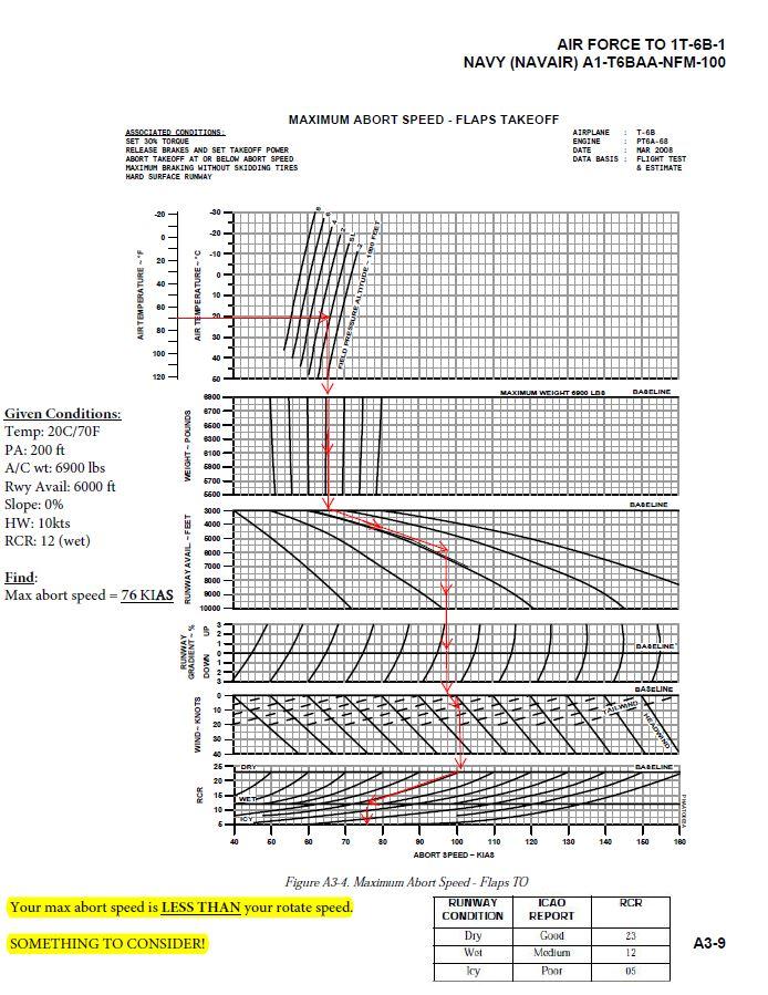
38 AIR FORCE TO 1T-6B-1 NAVY (NAVAIR) A1-T6BAA-NFM-100 Takeoff Ground Run Distance Takeoff ground run distance is defined as that runway distance from brake release to lift-off. It is achieved by following the normal takeoff distance associated procedures for a given rotation speed, at the mission-specified weight, ambient temperature, pressure altitude, runway wind and gradient, and appropriate takeoff configuration. Maximum Braking Speed (V B ) Maximum braking speed is the maximum speed from which the aircraft can be brought to a stop without exceeding the maximum design energy absorption capability of the brakes (3.96 Million ft-lb). Maximum Abort Speed Maximum abort speed is the maximum speed at which an abort may be started and the aircraft stopped within the remaining runway length. Allowances included in the data are based on a 3-second reaction at Maximum Abort Speed to recognize decision to abort and select idle power, during which time acceleration continues. Additional allowance includes a 3-second period to apply the brakes after idle power is selected. Speed may increase up to 20 knots during this 6-second period. When the abort speed is above rotation speed, rotation speed (V R ) becomes the abort speed. For operation with a tailwind, maximum braking speed limits should be observed (Figure A3-2). If the abort speed is greater than the maximum braking speed less 20 knots, the maximum braking speed (less 20 knots) becomes the abort speed. Lift-off Lift-off is the moment during takeoff at which 100% of the aircraft weight is first supported by aerodynamic forces and no tires are in contact with the runway. Distance to 50-foot Obstacle Distance to 50-foot obstacle is the sum of the takeoff ground run distance, plus the airborne horizontal distance needed to accelerate and climb to the 50-foot obstacle height at or above the obstacle climbout speed. Rotation Speed Rotation speed (V R ) is the speed which permits attaining obstacle speed at the 50-foot obstacle height above the runway. Obstacle Speed Obstacle speed (V OBS ) is the target speed at which the aircraft crosses the 50-foot obstacle height while accelerating to 140 KIAS at a 15 pitch attitude. Stall Speed (V S ) Stall speed is the higher of: 1. The airspeed at which the aircraft ceases to fly due to the loss of aerodynamic lift with the input of slow smooth control movements; or 2. The minimum controllable steady flight speed. Climb Gradient Climb gradient is the measured change of geometric altitude versus horizontal distance, typically feet per nautical mile. Charts which present climb gradient are calculated on actual (gross) climb performance. FACTORS AFFECTING TAKEOFF Wind Corrections Accounting for wind when planning takeoff requires that the wind direction and speed known. The headwind, tailwind, or crosswind component can then be determined using the Takeoff and Landing Crosswind chart in Figure A3-6. Headwind and Tailwind The wind grids include factors of 50% for steady state headwinds and 150% for steady state tailwinds. Reported wind components may therefore be apllied directly to the chart. Crosswind When determining the crosswind component, enter the Takeoff and Landing Crosswind chart with the sum of the steady wind value plus the gust increment. The maximum demonstrated dry runway crosswind for takeoff and landing is 25 knots. Gusts The gust increment is obtained from ground meteorological sources. It is the difference between the reported steady wind velocity and the reported peak gust velocity. Increase takeoff speeds by 50% of the gust increment up to a maximum increase of 10 knots. A3-2
39
40 Ejection Seat Sequencing Mitigation Procedures Dual Flights ISS Mode Selector SOLO in flight (Before Takeoff checks) RCP occupant shall initiate ejection ON third EJECT call FCP occupant shall initiate ejection NET ~0.5 sec AFTER third EJECT call Solo Flights Normal NATOPS Procedures Apply Ensure ISS Mode Selector is in SOLO CRM RCP Delaying Ejection May lead to collision with FCP seat RCP shall not hesitate or delay ejecting RCP occupant shall initiate ejection ON third EJECT call FCP Initiating Ejection Too Soon May lead to collision with RCP seat FCP shall initiate ejection NET ~0.5 sec after third EJECT call Contingencies FCP Incapacitation 1. ISS Mode Selector BOTH 2. RCP Eject ICS Failure Face curtain signal serves as the prepatory command during a controlled ejection. A thumbs up from each occupant is required to initiate ejection sequence. FCP shall initiate ejection sequence with three raps of the canopy RCP occupant shall initiate ejection ON third rap FCP occupant shall initiate ejection NET ~0.5 seconds AFTER third rap Misc Unqualified personnel prohibited Must be NATOPS qualified, enrolled in a formal aviation syllabus, or an observer qualified Naval Flight Officer, Flight Surgeon, or Aeromedical Safety Officer Delaying ejection below 2,000 ft AGL is not recommended Any delays may negatively impact the ejection envelope FCP occupant initiates ejection NET ~0.5 sec AFTER third EJECT call or immediately after confirming the RCP occupant has ejected Proper manual ejection sequencing requires the RCP occupant to eject prior to the FCP occupant
C2103 Briefing Guide (Worksheet)
") T-6B JPPT 1542.166B Simulator Event Briefing Guide C2103 Briefing Guide (Worksheet) Planned Route: Takeoff: KNSE, Rwy 05 Altitude: MOA Limits Route: North MOA Training Device: UTD/OFT SYLLABUS S: Students
T-6B JPPT 1542.166B Simulator Event Briefing Guide C2103 Briefing Guide (Worksheet) Planned Route: Takeoff: KNSE, Rwy 05 Altitude: MOA Limits Route: North MOA Training Device: UTD/OFT SYLLABUS S: Students
C3301 Briefing Guide (Worksheet)
") T-6B JPPT 1542.166B Simulator Event Briefing Guide C3301 Briefing Guide (Worksheet) Planned Route: Takeoff: Altitude: Route: Training Device: KNSE, Runway 32 VFR to North 5500' MSL KNSE, Brewton or Evergreen
T-6B JPPT 1542.166B Simulator Event Briefing Guide C3301 Briefing Guide (Worksheet) Planned Route: Takeoff: Altitude: Route: Training Device: KNSE, Runway 32 VFR to North 5500' MSL KNSE, Brewton or Evergreen
Q2101 Briefing Guide (Worksheet)
") T-6B JPPT 1542.165A Simulator Event Briefing Guide Q2101 Briefing Guide (Worksheet) Planned Route: Takeoff: KNSE, Rwy 05 Altitude: MOA Limits Route: North MOA Training Device: UTD/OFT IUT NATOP flights
T-6B JPPT 1542.165A Simulator Event Briefing Guide Q2101 Briefing Guide (Worksheet) Planned Route: Takeoff: KNSE, Rwy 05 Altitude: MOA Limits Route: North MOA Training Device: UTD/OFT IUT NATOP flights
I2103 WORKSHEET. Planned Route: Takeoff: KNSE, RWY 32 Altitude: 12,000 Route: RADAR DEPARTURE. Syllabus Notes None
 Planned Route: Takeoff: KNSE, RWY 32 Altitude: 12,000 Route: RADAR DEPARTURE Syllabus Notes None I2103 WORKSHEET Special Syllabus Requirements Proceed direct to homefield using any available NAVAID. Discuss
CIVIL AIR PATROL United States Air Force Auxiliary Cadet Program Directorate. Cessna 172 Maneuvers and Procedures
 CIVIL AIR PATROL United States Air Force Auxiliary Cadet Program Directorate Cessna 172 Maneuvers and Procedures This study guide is designed for the National Flight Academy Ground School. The information
I2102 WORKSHEET. Planned Route: Takeoff: KNSE, RWY 32 Altitude: 12,000 Route: RADAR DEPARTURE. Syllabus Notes None. Special Syllabus Requirements None
 Planned Route: Takeoff: KNSE, RWY 32 Altitude: 12,000 Route: RADAR DEPARTURE Syllabus Notes None Special Syllabus Requirements None I2102 WORKSHEET Discuss a. IMC Emergencies NATOPS statement on sound
See the diagrams at the end of this manual for judging position locations.
 Landing Events Penalties General Judges should use airport diagrams, satellite pictures or other means to determine, as accurately as possible, assessments of landing pattern penalties. Judges should be
Q3102 Briefing Guide (Worksheet)
") T-6B JPPT 1542.165A Simulator Event Briefing Guide Q3102 Briefing Guide (Worksheet) Planned Route: Takeoff: KNSE, Rwy 32 MOA Limits Altitude: South MOA or North MOA Route: Training Device: OFT SYLLABUS
T-6B JPPT 1542.165A Simulator Event Briefing Guide Q3102 Briefing Guide (Worksheet) Planned Route: Takeoff: KNSE, Rwy 32 MOA Limits Altitude: South MOA or North MOA Route: Training Device: OFT SYLLABUS
CESSNA 172-SP PRIVATE & COMMERCIAL COURSE
 CESSNA 172-SP PRIVATE & COMMERCIAL COURSE University of Dubuque INTENTIONALLY LEFT BLANK Revision 1 Standard Operating Procedures 1 CALLOUTS CONDITION Parking Brake Released After Takeoff Power has been
NORMAL TAKEOFF AND CLIMB
 NORMAL TAKEOFF AND CLIMB CROSSWIND TAKEOFF AND CLIMB The normal takeoff is one in which the airplane is headed directly into the wind or the wind is very light, and the takeoff surface is firm with no
Jabiru J230-SP Section 10
 Jabiru J230-SP Section 10 Section 10 10.1 Introduction This section contains information on the basic flight controls, door operation, and entry and egress, followed by a flight training outline compiled
Tecnam Eaglet Standard Operating Procedures and Maneuvers Supplement
 Tecnam Eaglet Standard Operating Procedures and Maneuvers Supplement Normal Takeoff Flaps Take Off Trim set Fuel pump on Check for traffic Line up on white stripe Full power Stick should be located in
PROCEDURES GUIDE. FLIGHT MANEUVERS for the SPORT PILOT
 Page 1 of 10 PROCEDURES GUIDE FLIGHT MANEUVERS for the SPORT PILOT * Author s Note: Whereas this procedures guide has been written for a specific application, it can easily be modified to fit many different
Visualized Flight Maneuvers Handbook
 Visualized Flight Maneuvers Handbook For High Wing Aircraft Third Edition For Instructors and Students Aviation Supplies & Academics, Inc. Newcastle, Washington Visualized Flight Maneuvers Handbook for
PERFORMANCE MANEUVERS
 Ch 09.qxd 5/7/04 8:14 AM Page 9-1 PERFORMANCE MANEUVERS Performance maneuvers are used to develop a high degree of pilot skill. They aid the pilot in analyzing the forces acting on the airplane and in
PROCEDURES GUIDE CESSNA 172N SKYHAWK
 PROCEDURES GUIDE CESSNA 172N SKYHAWK THESE PROCEDURES ARE DESIGNED TO PROVIDE STANDARDIZED METHODS UNDER NORMAL CONDITIONS. AS CONDITIONS CHANGE, THE PROCEDURES WILL NEED TO BE ADJUSTED. PASSENGER BRIEFING
TAILWHEEL AIRPLANES LANDING GEAR TAXIING
 Ch 13.qxd 5/7/04 10:04 AM Page 13-1 TAILWHEEL AIRPLANES Tailwheel airplanes are often referred to as conventional gear airplanes. Due to their design and structure, tailwheel airplanes exhibit operational
CAP-USAF FLIGHT MANEUVERS GUIDE
 CAP-USAF FLIGHT MANEUVERS GUIDE February 2012 Flight Maneuvers Guide This guide describes and standardizes the instruction and performance of the various flight maneuvers described in Chapter 3 of AFI11-2CAP-USAF,
Cessna 152 Standardization Manual
 Cessna 152 Standardization Manual This manual is to be utilized in conjunction with the manufacturers approved POH/ AFM and the Airplane Flying Handbook (FAA-H-8083-3A). This manual should be used as a
C-130 Reduction in Directional Stability at Low Dynamic Pressure and High Power Settings
 C-130 Reduction in Directional Stability at Low Dynamic Pressure and High Power Settings The C-130 experiences a marked reduction of directional stability at low dynamic pressures, high power settings,
C3101 Briefing Guide (Worksheet)
") T-6B JPPT 1542.165B Simulator Event Briefing Guide C3101 Briefing Guide (Worksheet) Planned Route: Takeoff: KNSE, Rwy 32 Altitude: Working area limits Route: NMOA or Pelican, Brewton or Evergreen, KNSE
T-6B JPPT 1542.165B Simulator Event Briefing Guide C3101 Briefing Guide (Worksheet) Planned Route: Takeoff: KNSE, Rwy 32 Altitude: Working area limits Route: NMOA or Pelican, Brewton or Evergreen, KNSE
Cessna 172S Skyhawk Standardization Manual
 Cessna 172S Skyhawk Standardization Manual This manual is to be utilized in conjunction with the manufacturers approved POH/ AFM and the Airplane Flying Handbook (FAA-H-8083-3A). This manual should be
Piper PA Seminole 1. Standardization Manual
 Piper PA-44-180 Seminole Standardization Manual This manual is to be utilized in conjunction with the manufacturers approved POH/AFM and the Airplane Flying Handbook (FAA-H-8083-3A). This manual should
Flight Profiles are designed as a guideline. Power settings are recommended and subject to change based
 MANEUVERS AND PROCEDURES Flight Profiles are designed as a guideline. Power settings are recommended and subject to change based upon actual conditions (i.e. aircraft weight, pressure altitude, icing conditions,
NORMAL TAKEOFF PILOT TRAINING MANUAL KING AIR 200 SERIES OF AIRCRAFT
 NORMAL TAKEOFF Climb-Out 1. Accelerate to 160 KIAS 2. Landing/Taxi lights: Out 3. Climb Checklist complete 1. 160 KIAS up to 10,000 ft 2. Decrease 2 KIAS per 1,000 ft above 10,000 ft to 130 KIAS at 25,000
VII.E. Normal and Crosswind Approach and Landing
 References: FAA-H-8083-3; POH/AFM Objectives Key Elements Elements Schedule Equipment IP s Actions SP s Actions Completion Standards The student should be able to perform a normal approach and landing
Single Engine Complex Training Supplement PA28R-201 Piper Arrow III (Spring 2016 Revision)
") Single Engine Complex Training Supplement PA28R-201 Piper Arrow III (Spring 2016 Revision) V-speed Quick Reference V-Speed KIAS Description Airspeed Indicator Marking VSO 55 Stall speed in landing configuration
Single Engine Complex Training Supplement PA28R-201 Piper Arrow III (Spring 2016 Revision) V-speed Quick Reference V-Speed KIAS Description Airspeed Indicator Marking VSO 55 Stall speed in landing configuration
XI.B. Power-On Stalls
 XI.B. Power-On Stalls References: AC 61-67; FAA-H-8083-3; POH/AFM Objectives Key Elements Elements Schedule Equipment IP s Actions SP s Actions Completion Standards The student should develop knowledge
MANEUVERS GUIDE. Liberty Aerospace 1383 General Aviation Drive Melbourne, FL (800)
") MANEUVERS GUIDE Liberty Aerospace 1383 General Aviation Drive Melbourne, FL 32935 (800) 759-5953 www.libertyaircraft.com Normal/Crosswind Takeoff and Climb 1. Complete the runup and before takeoff checklist.
MANEUVERS GUIDE Liberty Aerospace 1383 General Aviation Drive Melbourne, FL 32935 (800) 759-5953 www.libertyaircraft.com Normal/Crosswind Takeoff and Climb 1. Complete the runup and before takeoff checklist.
Front Cover Picture Mark Rasmussen - Fotolia.com
 Flight Maneuvers And Stick and Rudder Skills A complete learn to fly handbook by one of aviation s most knowledgeable and experienced flight instructors Front Cover Picture Mark Rasmussen - Fotolia.com
FAA-S-ACS-6 June 2016 Private Pilot Airplane Airman Certification Standards. Task ACS Settings
 FAA-S-ACS-6 June 2016 Private Pilot Airplane Airman Certification Standards Cessna 172: mixture rich, carb heat out if below the green arc. Clearing Turns all manuevers! Task ACS Settings Traffic Pattern
CHAPTER 8 MANEUVERS TABLE OF CONTENTS
 CHAPTER 8 MANEUVERS TABLE OF CONTENTS Transition Airspeeds... 3 Checklists and callouts during maneuvers... 3 Guidance to better maneuver execution... 3 Taxiing... 5 Pre-Maneuver Checklist... 6 Clearing
SUPPLEMENT SEPTEMBER 2010 HIGH ALTITUDE TAKEOFF AND LANDING (ABOVE 14,000 FEET PRESSURE ALTITUDE) MODEL AND ON 68FM-S28-00 S28-1
 MODEL AND ON 68FM-S28-00 S28-1") MODEL 680 680-0001 AND ON HIGH ALTITUDE TAKEOFF AND LANDING (ABOVE 14,000 FEET PRESSURE ALTITUDE) COPYRIGHT 2010 CESSNA AIRCRAFT COMPANY WICHITA, KANSAS, USA 15 SEPTEMBER 2010 S28-1 SECTION V - SUPPLEMENTS
MODEL 680 680-0001 AND ON HIGH ALTITUDE TAKEOFF AND LANDING (ABOVE 14,000 FEET PRESSURE ALTITUDE) COPYRIGHT 2010 CESSNA AIRCRAFT COMPANY WICHITA, KANSAS, USA 15 SEPTEMBER 2010 S28-1 SECTION V - SUPPLEMENTS
VFR Circuit Tutorial. A Hong Kong-based Virtual Airline. VOHK Training Team Version 2.1 Flight Simulation Use Only 9 July 2017
 A Hong Kong-based Virtual Airline VFR Circuit Tutorial VOHK Training Team Version 2.1 Flight Simulation Use Only 9 July 2017 Copyright 2017 Oasis Hong Kong Virtual Page 1 Oasis Hong Kong Virtual (VOHK)
XI.C. Power-Off Stalls
 References: FAA-H-8083-3; POH/AFM Objectives Key Elements Elements Schedule Equipment IP s Actions SP s Actions Completion Standards The student should develop knowledge of stalls regarding aerodynamics,
OFFICE HOURS Monday through Friday, 7:30 a.m. to 4:30 p.m., Pacific Time. Lunch hour is 11:30 a.m. to 12:30 p.m.
 Robinson Helicopter Company Phone: (310) 539-0508 2901 Airport Drive Fax: (310) 539-5198 Torrance, California 90505-6115 Web: www.robinsonheli.com United States of America OFFICE HOURS Monday through Friday,
C2201 Briefing Guide (Worksheet)
") T-6B JPPT 1542.166A Simulator Event Briefing Guide C2201 Briefing Guide (Worksheet) Planned Route: Takeoff: KNSE, Rwy 05 Altitude: MOA Limits Route: North MOA Training Device: UTD / OFT SYLLABUS S: Introduce
T-6B JPPT 1542.166A Simulator Event Briefing Guide C2201 Briefing Guide (Worksheet) Planned Route: Takeoff: KNSE, Rwy 05 Altitude: MOA Limits Route: North MOA Training Device: UTD / OFT SYLLABUS S: Introduce
Compiled by Matt Zagoren
 The information provided in this document is to be used during simulated flight only and is not intended to be used in real life. Attention VA's - you may post this file on your site for download. Please
Cessna 172R Profiles
 Cessna 172R Profiles TRAFFIC PATTERNS (Verify pattern altitude) Start your first climbing turn within 300' of pattern altitude Enter 45 degree angle to the downwind leg Depart the traffic pattern straight-out,
C3201 Briefing Guide (Worksheet)
") T-6B JPPT 1542.166B Simulator Event Briefing Guide C3201 Briefing Guide (Worksheet) Planned Route: Takeoff: Altitude: Route: Training Device: KNSE, Rwy 05 MOA Limits KNSE, North MOA, Brewton, Evergreen,
T-6B JPPT 1542.166B Simulator Event Briefing Guide C3201 Briefing Guide (Worksheet) Planned Route: Takeoff: Altitude: Route: Training Device: KNSE, Rwy 05 MOA Limits KNSE, North MOA, Brewton, Evergreen,
Bonanza/Debonair Pilots
 Bonanza/Debonair Pilots Completing this worksheet is a great way to reinforce the proper speeds for operating your Bonanza or Debonair under varying operating conditions, and to understand the changes
S-Tec System 55 Autopilot
 Cirrus Design Section 9 Pilot s Operating Handbook and FAA Approved Airplane Flight Manual Supplement for S-Tec System 55 Autopilot When the S-Tec System 55 Autopilot is installed in the Cirrus Design,
Cessna 172 Profiles. TRAFFIC PATTERNS (Check Chart Supplement prior to flight) Index
 Index") Cessna 172 Profiles TRAFFIC PATTERNS (Check Chart Supplement prior to flight) Index When Cleared for Takeoff - Landing/Taxi lights ON Mixture-As Required Power-Check Takeoff RPM Power Climb at Vy Start
Cessna 172 Profiles TRAFFIC PATTERNS (Check Chart Supplement prior to flight) Index When Cleared for Takeoff - Landing/Taxi lights ON Mixture-As Required Power-Check Takeoff RPM Power Climb at Vy Start
IV. AREA OF OPERATION: TAKEOFFS, LANDINGS, AND GO AROUNDS A. TASK: NORMAL AND CROSSWIND TAKEOFF AND CLIMB
 IV. AREA OF OPERATION: TAKEOFFS, LANDINGS, AND GO AROUNDS A. TASK: NORMAL AND CROSSWIND TAKEOFF AND CLIMB FAA-H-8083-3; POH/AFM NOTE: If a crosswind condition does not exist, the applicant's knowledge
TERMS AND DEFINITIONS
 Ch 05.qxd 5/7/04 7:02 AM Page 5-1 GENERAL This chapter discusses takeoffs and departure climbs in tricycle landing gear (nosewheel-type) airplanes under normal conditions, and under conditions which require
Autothrottle Use with Autopilot Off
 Autothrottle Use with Autopilot Off Bill McKenzie Flight Crew Operations Boeing Commercial Airplanes May 2004 757.1 What Is Pitch Coupling The thrust vector for engines mounted under the wing will cause
VI.B. Traffic Patterns
 References: FAA-H-8083-3; FAA-H-8083-25; AC 90-42; AC90-66; AIM Objectives Key Elements Elements Schedule Equipment IP s Actions SP s Actions Completion Standards The student should develop knowledge of
Discuss: 1. Instrument Flight Checklist
 INST 1 Prerequisites: 1. OFT: Tac 1 2. CBT: Basic Instrument Flight, IFR Navigation I & II Lessons P2 501, P2 502, & P2 503. Discuss: 1. Instrument Flight Checklist NATOPS 13.1.3 Instrument Flight Checklist
OFFICE HOURS Monday through Friday, 7:30 a.m. to 4:30 p.m., Pacific Time. Lunch hour is 11:30 a.m. to 12:30 p.m.
 Robinson Helicopter Company Phone: (310) 539-0508 2901 Airport Drive Fax: (310) 539-5198 Torrance, California 90505-6115 Web: www.robinsonheli.com United States of America OFFICE HOURS Monday through Friday,
Guidance Notes PRIVATE AND COMMERCIAL PILOT TRAINING
 PRIVATE AND COMMERCIAL PILOT TRAINING September 2005 1 st Edition ACKNOWLEDGEMENT Transport Canada thanks the Federal Aviation Administration of the United States for their permission to use the chapter
Gleim Private Pilot Flight Maneuvers Seventh Edition, 1st Printing Updates February 2018
 Page 1 of 11 Gleim Private Pilot Flight Maneuvers Seventh Edition, 1st Printing Updates February 2018 If you are tested on any content not represented in our materials or this update, please share this
Climbs, descents, turns, and stalls These are some of the maneuvers you'll practice, and practice, and practice By David Montoya
 Climbs, descents, turns, and stalls These are some of the maneuvers you'll practice, and practice, and practice By David Montoya Air work stalls, steep turns, climbs, descents, slow flight is the one element
Noise Abatement Takeoff 1 Close In Profile
 PF Duties Captain: Advance thrust to 70% N1 (Allow Engines to stabilize) Noise Abatement Takeoff 1 Close In Profile Flaps Increase Speed to Vref 30 +80kts Climb Checklist Push N1 Button to set Takeoff
POWER-OFF 180 ACCURACY APPROACH AND LANDING
 POWER-OFF 180 ACCURACY APPROACH AND LANDING OBJECTIVE To teach the commercial student the knowledge of the elements related to a power-off 180 accuracy approach and landing. COMPLETION STANDARDS 1. Considers
Beechcraft Duchess 76 Maneuver Notes
 Beechcraft Duchess 76 Maneuver Notes I. Maneuver notes for Performance (AOA V), Slow Flight and Stalls (AOA VIII), Emergency Operations (AOA X), and Multiengine Operations (AOA XI) a. Maneuvers addressed:
ABS/BPPP Performance Worksheet: Baron/Travel Air Pilots
 ABS/BPPP Performance Worksheet: Baron/Travel Air Pilots This worksheet is the homework for BPPP Initial pilots to complete before their BPPP flight. It s designed to help the pilot develop a deep understanding
Airplane Flying Handbook. Figure 6-4. Rectangular course.
 Airplane Flying Handbook Rectangular Course Figure 6-4. Rectangular course. Normally, the first ground reference maneuver the pilot is introduced to is the rectangular course. [Figure 6-4] The rectangular
Things to remember when flying N102RE or any Taildragger
 Page 1 of 8 Things to remember when flying N102RE or any Taildragger 1. The Center of Gravity (CG) is behind the main between a taildragger (i.e. conventional gear airplane) and a tricycle gear airplane
Commercial Maneuvers for PA28RT-201
 Commercial Maneuvers for PA28RT-201 Cruise checklist: Power 23'', 2400 RPM (23, 24) Lean mixture Fuel Pump Off (Check positive fuel pressure) Landing light Off Pre-Maneuver Checklist in the Takeoff configuration
C-182P MANEUVERS GUIDE TABLE OF CONTENTS
 INTRODUCTION The following maneuver guide is designed to provide a technique for completing each VFR maneuver required by the FAA s Practical Test Standards for the Private Practical Test. By performing
IVAO International Virtual Aviation Organization Training department
 1 Introduction IVAO International Virtual Aviation Organization Training department TRAFFIC PATTERN DESCRIPTION An aerodrome traffic pattern is used by VFR traffic for training purpose or to prepare the
Pre Solo Written For Schweizer 2-33 Glider. Eagles Sport Aviation Club
 Pre Solo Written For Schweizer 2-33 Glider Eagles Sport Aviation Club Student Date: Instructor 1) What is the maximum gross weight for the 2-33? Empty Weight? 2) What position should the trim level be
Circuit Considerations
 Circuit Training Circuit Considerations This briefing deals with those aspects of a normal circuit that were deferred during Circuit Introduction, to avoid student overload. Objectives To continue circuit
Circuit Introduction. Considerations. Circuit Training
 Circuit Training Circuit Introduction The circuit is an orderly pattern used to position the aeroplane for landing and minimise the risk of collision with other aircraft. Airfields attract aircraft, therefore
I2101 SIMULATOR ABBREVIATED CHECKLIST
 WORKSHEET I2101 SIMULATOR ABBREVIATED CHECKLIST Planned Route: Takeoff: KNSE, RWY 32 Altitude: 12,000 Route: PENSACOLA NORTH MOA Special Syllabus Requirements: -None Discuss Items a. Departures Four basic
Cessna Aircraft Short & Soft Field Takeoff & Landing Techniques
 Cessna Aircraft Short & Soft Field Takeoff & Landing Techniques Introduce speaker. 1 Objectives / Content For short- and soft-field takeoff and landing operations in CAP Cessna aircraft, review: Standards
VII.H. Go-Around/Rejected Landing
 VII.H. Go-Around/Rejected Landing References: FAA-H-8083-3; POH/AFM Objectives Key Elements Elements Schedule Equipment IP s Actions SP s Actions Completion Standards The student should develop knowledge
II.E. Airplane Flight Controls
 References: FAA-H-8083-3; FAA-8083-3-25 Objectives Key Elements Elements Schedule Equipment IP s Actions SP s Actions Completion Standards The student should develop knowledge of the elements related to
Normal T/O Procedure. Short Field T/O Procedure
 Normal T/O Procedure Add full power: Engine Instruments green Airspeed alive 1,000 AGL Accelerate to enroute climb 85 KIAS Complete climb check Vr = 55-60 Vy 79 KIAS Prior to Receiving T/O Clearance Complete
TRAWING FIVE T-6B TEXAN II CHECKLIST STUDY GUIDE PRIMARY FLIGHT TRAINING
 COMTRAWINGFIVEINST 3710.17B TRAWING FIVE T-6B TEXAN II CHECKLIST STUDY GUIDE PRIMARY FLIGHT TRAINING MARCH 2018 Commander, Training Air Wing FIVE (CTW-5) NAS Whiting Field, Milton, FL COMTRAWINGFIVEINST
C-182P MANEUVERS GUIDE TABLE OF CONTENTS
 INTRODUCTION The following maneuver guide is designed to provide a technique for completing each VFR maneuver required by the FAA s Practical Test Standards for the Private Practical Test. By performing
 interaction of the aircraft with the given wind conditions and power changes. This will aid in timing the descent for touchdown. During the landing, as the aircraft nears the deck for touchdown, the pilot
XI.D. Crossed-Control Stalls
 References: FAA-H-8083-3; POH/AFM Objectives Key Elements Elements Schedule Equipment IP s Actions SP s Actions Completion Standards The student should understand the dynamics of a crossed-control stall
TECHNIQUES FOR OFF AIRPORT OPERATIONS
 Off Airport Ops Guide TECHNIQUES FOR OFF AIRPORT OPERATIONS Note: This document suggests techniques and procedures to improve the safety of off-airport operations. It assumes that pilots have received
PRIVATE PILOT MANEUVERS Practical Test Standards FAA-S A
 PRIVATE PILOT MANEUVERS Practical Test Standards FAA-S-8081-15A Special Emphasis Areas Examiners shall place special emphasis upon areas of aircraft operation considered critical to flight safety. Among
WIPLINE 3450 SEAPLANE FLOATS
 FOUND SUPPLEMENT M400-S08 Transport Canada Approved Flight Manual Supplement For WIPLINE MODEL 3450 SEAPLANE FLOATS This supplemental manual is applicable to Wipline Model 3450 seaplane float equipped
Aviation Merit Badge Knowledge Check
 Aviation Merit Badge Knowledge Check Name: Troop: Location: Test Score: Total: Each question is worth 2.5 points. 70% is passing Dan Beard Council Aviation Knowledge Check 1 Question 1: The upward acting
I2201 WORKSHEET. Planned Route: Takeoff: KSAT, RWY 31R Altitude: 6,000 Route: KRND via Radar vectors RND KSAT Airport Diagram
 I2201 WORKSHEET Planned Route: Takeoff: KSAT, RWY 31R Altitude: 6,000 Route: KRND via Radar vectors RND KSAT Airport Diagram Syllabus Notes None Special Syllabus Requirements None Discuss a. HSI orientation
SF50 Airplane Flight Manual (AFM) Temporary Change
 Temporary Change") CIRRUS TAFM AFM Temporary Change SF50 Airplane Flight Manual (AFM) Temporary Change Information in this Temporary Change adds to, supersedes, or deletes information in the basic Airplane Flight Manual.
CIRRUS TAFM AFM Temporary Change SF50 Airplane Flight Manual (AFM) Temporary Change Information in this Temporary Change adds to, supersedes, or deletes information in the basic Airplane Flight Manual.
Medium, Climbing and Descending Turns
 Basic Concepts Medium, Climbing and Descending Turns A medium turn is defined as a turn using up to 30 degrees angle of bank. Climbing and descending turns are combined with medium turns within this briefing,
Takeoffs & Landings Refresher. By Wally Moran
 Takeoffs & Landings Refresher By Wally Moran About Wally Moran Wally Moran is a retired airline captain and spent much of his career as a training instructor and check airman on aircraft including the
STUDY OF LANDING TECHNIQUE DURING VISUAL APPROACH
 24 TH INTERNATIONAL CONGRESS OF THE AERONAUTICAL SCIENCES STUDY OF LANDING TECHNIQUE DURING VISUAL APPROACH Hiroshi TAKAHARA*, Takashi KONDO*, Shinji SUZUKI** *All Nippon Airways Co., LTD., **University
X.A. Rectangular Course
 References: FAA-H-8083-3 Objectives Key Elements Elements Schedule Equipment IP s Actions SP s Actions Completion Standards The student should develop knowledge of the elements related to rectangular courses
izations Northr Version 1.3
 Military Visual izations Northr rop T-38A Quick Start Guide Version 1.3 Welcome, Lieutenant to the T 38. You have shown that you may have the stuff to be a combat pilot in fighters or bombers. However,
SR22 Airplane Flight Manual (AFM) Temporary Change
 Temporary Change") Cirrus Design TPOH AFM Temporary Change Airplane Flight Manual (AFM) Temporary Change Information in this Temporary Change adds to, supersedes, or deletes information in the basic Pilot s Operating Handbook.
Cirrus Design TPOH AFM Temporary Change Airplane Flight Manual (AFM) Temporary Change Information in this Temporary Change adds to, supersedes, or deletes information in the basic Pilot s Operating Handbook.
Aerodynamics Principles
 Aerodynamics Principles Stage 1 Ground Lesson 3 Chapter 3 / Pages 2-18 3:00 Hrs Harold E. Calderon AGI, CFI, CFII, and MEI Lesson Objectives Become familiar with the four forces of flight, aerodynamic
X.B. S-Turns. References: FAA-H The student should develop knowledge of the elements related to S-turns as necessary in the Private Pilot PTS.
 References: FAA-H-8083-3 Objectives Key Elements Elements Schedule Equipment IP s Actions SP s Actions Completion Standards The student should develop knowledge of the elements related to S-turns as necessary
C2201 Briefing Guide (Worksheet)
") T-6B JPPT 1542.166B Simulator Event Briefing Guide C2201 Briefing Guide (Worksheet) Planned Route: Takeoff: KNSE, Rwy 05 Altitude: MOA Limits Route: North MOA Training Device: UTD / OFT SYLLABUS S: Introduce
T-6B JPPT 1542.166B Simulator Event Briefing Guide C2201 Briefing Guide (Worksheet) Planned Route: Takeoff: KNSE, Rwy 05 Altitude: MOA Limits Route: North MOA Training Device: UTD / OFT SYLLABUS S: Introduce
Mountain Fury Mountain Search Flying Course Syllabus
 Mountain Fury Mountain Search Flying Course Syllabus Goals 1. Pilots who complete this program will be able to perform with precision and confidence all of the tasks and flight maneuvers required for safe
Winnipeg Headingley Aero Modellers. Things About Airplanes.
 Winnipeg Headingley Aero Modellers Things About Airplanes. Table of Contents Introduction...2 The Airplane...2 How the Airplane is Controlled...3 How the Airplane Flies...6 Lift...6 Weight...8 Thrust...9
Flying The Boeing Advanced
 Flying The Boeing 727-200 Advanced This section includes Pilot s Operating Handbook and Checklists. The POH section is first, followed by the Checklists. FOM: This section includes performance data on
VIII.A. Straight and Level Flight
 VIII.A. Straight and Level Flight References: FAA-H-8083-3; FAA-H-8083-25 Objectives Key Elements Elements Schedule Equipment IP s Actions SP s Actions Completion Standards The student should develop the
General. Procedure Checklists. Emergency Procedures. FSD Aerostar 700P Superstar
 General The recommended procedures for coping with various types of emergencies and critical situations are provided in this section. These procedures are suggested as a course of action for coping with
1 In The Biginning. Nice Air Operation Procedure Cessna 172
 1 In The Biginning Check how many hours remains for next 100h inspection and check squawk before take airplane. Perform pre-flight inspection using check list. Report to the front desk if you need fuel,
FFI Formation Guidelines and Standard Procedures Mooney Supplement (28 Dec, 2018; Rev 12)
") FFI Formation Guidelines and Standard Procedures Mooney Supplement (28 Dec, 2018; Rev 12) This document describes formation flight differences between RV and Mooney aircraft. In conjunction with the FFI
FFI Formation Guidelines and Standard Procedures Mooney Supplement (28 Dec, 2018; Rev 12) This document describes formation flight differences between RV and Mooney aircraft. In conjunction with the FFI
VI.B. Traffic Patterns
 References: FAA-H-8083-3; FAA-H-8083-25; AC 90-42; AC90-66; AIM Objectives Key Elements Elements Schedule Equipment IP s Actions SP s Actions Completion Standards The student should develop knowledge of
Stalls and Spins. Tom Johnson CFIG
 Stalls and Spins Tom Johnson CFIG Contents Angle of Attack Stall Recognition and Recovery Spin Entry and Recovery Load Limit Considerations Gust Induced Stall and Spin Accidents Stalls a stall is a loss
FLIGHT AT MINIMUM CONTROLLABLE AIRSPEED
 INTRODUCTION The maintenance of lift and control of an airplane in flight requires a certain minimum airspeed. This critical airspeed depends on certain factors, such as gross weight, load factors, and
Student Pilot s Guide
 Student Pilot s Guide The Cirrus SR22 is a remarkably simple, safe and easy aircraft to fly. Angelina Jolie flying her own Cirrus. Key Words 1. My Airplane or I ve got it - means to let go of all controls
Maximum Rate Turns. Objective To carry out a balanced, maximum rate, level turn using full power.
 Advanced Manoeuvres Maximum Rate Turns To achieve the maximum rate of turn, the greatest possible force toward the centre of the turn is required. This is achieved by inclining the lift vector as far as