C3201 Briefing Guide (Worksheet)
|
|
|
- Shon Conley
- 5 years ago
- Views:
Transcription
1 T-6B JPPT B Simulator Event Briefing Guide C3201 Briefing Guide (Worksheet) Planned Route: Takeoff: Altitude: Route: Training Device: KNSE, Rwy 05 MOA Limits KNSE, North MOA, Brewton, Evergreen, KNSE OFT SYLLABUS NOTES: Introduce and practice the following during this block of training: Landing pattern procedures, Local departures and course rules, Local radio procedures, Engine malfunctions, PEL, Forced Landings and ELP s. No strap-in required for student. Need to have gloves, kneeboard, NATOPS PCL for this event. Student will use Abbreviated Simulator checklist to expedite becoming airborne. Once airborne all applicable checklist will be conducted from the quad-fold version. Discuss a. Engine Malfunctions (Any malfunction that leads to a PEL situation) Review Basic Handling of an Emergency FTI Guidance Procedures Ground School Handout Example on how to progress through the steps in a logical sequence (Tree Diagram) DME method Reaching Low Key during PEL/P DEGA Altitude method b. Precautionary Emergency Landing Horizontal glide distance Critical Action Items FTI procedures Emergency Voice Report Energy Management Techniques used to get to the ELP PEL in the landing pattern (PEL/P) FTI procedures Energy Management c. Emergency Landing Pattern General purpose Pattern Checkpoints Energy Management Techniques to fly to checkpoints Ejection Seat Sequence Mitigation Procedures JPPT B C3201 FTI Slip Procedures
2 T-6B CONTACT C3200 BLOCK STUDENT GRADE SHEET DATE INSTRUCTOR MEDIA: OFT VT- BRIEF TIME: NAME: EVENT: # MANEUVER MIF C3201 C3202 C GEN KNOWLEDGE / PROCEDURES 3+ X X X 2 EMERGENCY PROCEDURES 3+ X X X 3 HEADWORK / SITUATIONAL AWARENESS 2+ X X X 4 BASIC AIRWORK 3+ X X X 5 IN-FLIGHT CHECKS / FUEL MANAGEMENT 3+ X X X 6 IN-FLIGHT PLANNING / 2+ X X X AREA ORIENTATION 7 TASK MANAGEMENT 3+ X X X 8 COMMUNICATION 2+ X X X 9 MISSION PLANNING/BRIEFING/DEBRIEFING 2+ X X X 10 GROUND OPERATIONS 3+ X X X 11 TAKEOFF 3+ X X X 12 DEPARTURE 3+ X X X 13 G-AWARENESS / EXERCISE 2 14 TURN PATTERN 3 15 LEVEL SPEED CHANGE 3 16 SLOW FLIGHT 3 17 POWER-ON STALLS 2 18 LANDING PATTERN STALLS 2 19 POWER-OFF STALLS 2 20 SPIN 2+ X 21 CONTACT UNUSUAL ATTITUDES 2+ X 30 SLIP 2+ X 31 POWER LOSS 2+ X X 32 PRECAUTIONARY EMERGENCY LANDING 2+ X X X 33 PEL/P 2+ X X X 34 ELP LANDING 2+ X X X 35 ARRIVAL / COURSE RULES 2+ X X 36 LANDING PATTERN 2+ X X X 37 NO FLAP LANDING 2 37 TAKEOFF FLAP LANDING 2 37 LDG FLAP LANDING 2 37 FULL STOP LANDING 2+ X 39 WAVEOFF 2+ X X SPECIAL SYLLABUS REQUIREMENT 1 X SSR: C3202: At least one pattern and landing with the TAD off. NOTES: Introduce and practice the following: Ground operations, landing pattern procedures, local departures/course rules, local radio procedures, engine failures and malfunctions, PEL, forced landing procedures, and ELP. Discuss items: C3201: Engine malfunctions, PEL, and ELP. C3202: Engine failures, forced landing, and ejection. C3203: Crosswind takeoff/touch-and-go/full-stop landings, aborted takeoff, and aircraft departs a prepared surface. DEPART ARRIVE SIDE # SIM TIME JPPT B MAR 2017
3 CHAPTER SEVEN EMERGENCY PROCEDURES 700. INTRODUCTION This chapter forms the basis of your T-6B Emergency Procedures Training. A complete and thorough knowledge of the procedures in this chapter is essential for students who wish to progress to their solo flight. The memorization and proficient execution of these procedures will prove to be one of the greatest challenges to you during Primary Training. Remember the single most important factor in the execution of any emergency procedure is to first maintain control of the aircraft. After the aircraft is under control, you must then determine the precise nature of the problem. It is only at this point that you can execute the applicable emergency procedure and determine the appropriate landing criteria. No matter how well you know your procedures, if you lose control of the aircraft or misdiagnose the nature of the malfunction, you will not be successful in handling the emergency. Make sure that you are in control of the aircraft and understand what the problem is before you attempt to apply a solution. 1. Description. N/A 2. General. It is conceivable that during any flight evolution, an engine or system malfunction may occur either while on the ground or in flight. These malfunctions can range from system failures to a partial or complete power loss. The T-6B NATOPS Flight Manual, Section III, will be your governing publication for all EPs and the primary focus of your study and preparation. This chapter of the FTI merely expands and amplifies certain procedures from the NATOPS. If discrepancies exist between the FTI and the NATOPS manual, the NATOPS takes precedence. 3. Procedures. An emergency may occur at any altitude, airspeed and configuration. When presented with an emergency (actual or simulated), follow the three basic rules for handling an airborne emergency. a. Maintain aircraft control: Establishing the aircraft in safe controlled flight should always be your first priority in any emergency, even if it means consciously continuing in straight and level flight. Conversely, if performing aerobatic maneuvers, for example, and the master caution light illuminates, accomplish the appropriate VMC recovery and take care of flying the airplane before delving into the specifics of the caution. b. Analyze the situation and take proper action: Analyze the indications you have to determine the nature of the emergency. You should verify what you see in your cockpit with the other crewmember. Once the problem is diagnosed, apply boldfaced/asterisk items, then open your Pocket Checklist and with good aircrew coordination, continue with the emergency procedure. Consideration should be given to using RDO, FDO/ODO, or another aircraft for assistance as conditions persist. EMERGENCY PROCEDURES 7-1
4 CHAPTER SEVEN i. During airborne simulated emergency training, students will VERBALIZE the engine indications which may include Torque, ITT, N1, Np, Oil and Hydraulic pressure. Your instructor will verify indications and then give simulated engine indications and any EICAS messages that may apply. ii. iii. The student will then determine the cause of the emergency and take appropriate action by simulating applying the appropriate checklist procedures. Critical action items are to be conducted from memory without delay. Time permitting, break out the Pilot s Abbreviated Flight Crew Checklist (PCL) and conduct the appropriate checklist remaining items. NOTE During your airborne emergency procedure training, DO NOT actually manipulate switches or position the PCL to OFF in flight. When conducting simulated emergencies in flight, VERBALIZE emergency procedures that actually move switches or the PCL with the word simulated. For example, use PMU Switch Simulated Off. In response to PCL - Simulated Off, the instructor will set the power to 4-6% Torque to simulate a feathered propeller condition, when appropriate. c. Land as soon as conditions permit: The severity of the problem will dictate the course of action to take to safely recover the aircraft. Execution of emergency procedures will direct you to one of the following situations: Precautionary Emergency Landing (PEL), Forced Landing, Ejection, Land as soon as possible, or Land as soon as practical. Land As Soon As Possible: An emergency shall be declared and a landing accomplished at the nearest suitable landing area considering the severity of the emergency, weather conditions, field facilities, ambient lighting, and command guidance. Land As Soon As Practical: Emergency conditions are less urgent and, although the mission is to be terminated, the degree of the emergency is such that an immediate landing may not be necessary. 4. Common Errors. a. Not maintaining aircraft control. b. Improper analysis of aircraft malfunction c. Not remembering to Aviate, Navigate, Communicate in that order. 7-2 EMERGENCY PROCEDURES
5 How to handle an In-Flight Emergency Maintain aircraft control: Maneuver into and/or maintain attitude that allows the pilot to respond to the emergency situation. IF CURRENT ENGINE PERFORMANCE IS QUESTIONABLE (can t maintain altitude and airspeed), make an immediate TURN towards the nearest suitable landing runway and transition to your best glide speed by initiating a CLIMB to decelerate towards 125 KIAS (or descent if already 125 KIAS or less). Get the aircraft CLEAN, gear and flaps up (if able). IF FUTURE ENGINE PERORMANCE IS IN DOUBT, make an immediate TURN, to the nearest suitable landing runway while using appropriate power to establish a CLIMB (if additional altitude is not required, set 4-6% torque and transition to best glide speed of 125 KIAS). Get the aircraft CLEAN, gear and flaps up. IF ENGINGE PERFORMANCE IS NOT THE PROBLEM, establish and maintain controlled flight in appropriate direction, airspeed, and configuration. Analyze the situation and take proper action: Check and analyze indications o Aircraft performance o Warning and Indicator Lights and EICAS display o Other cockpit indications (visuals, noise, etc.) Determine the appropriate emergency procedure. You can t apply correct procedure if you don t know the problem!!!! Execute the appropriate emergency procedure (Begin at step 1) Land as soon as conditions permit: Defined by the urgency of emergency or malfunction and sound judgement Usually will end in one the following: o PEL o Forced Landing o Ejection o Land as soon as possible o Land as soon as practical
6 Uncommanded Power Changes/Loss of power/uncommanded Propeller Feather 1. Maintain aircraft control Perform Uncommanded Power Changes/Loss of power/uncommanded Propeller Feather procedure 2. Analyze the situation and take proper action Uncommanded Power Change/Loss of power Uncommanded reduction in power/thrust Np remains at 100% +/- 2 Uncommanded Propeller Feather Increase in TQ and decrease in NP Noticeable loss of thrust and prop noise PEL - Execute PCL Mid Range PMU Switch OFF Prop Sys circuit breaker (left front console) Pull, if Np stable below 40% PCL As required If power is sufficient for continued flight: If power is insufficient for continued flight: Turn to nearest suitable field (should have already started as part of maintain aircraft control) Climb or accelerate to intercept ELP (In progress from maintain aircraft control) Gear, flaps, speed brake UP FTI follow on : (Complete PCL non-memory items) - Check for secondary's - Boost pump as req - Ignition as req - Plan to intercept ELP Prop Sys circuit breaker Reset, as required PCL- OFF Firewall Shutoff handle Pull Execute Forced Landing or Eject If you on profile to make the runway, execute Forced Landing Airspeed 125 KIAS prior to extending landing gear Emerg LDG Gr handle- pull Airspeed 120 KIAS minimum until intercepting final: 110 KIAS minimum on final Flaps as required If you are not on profile to make the runway, execute Ejection (Time and altitude permitting consider controlled ejection) 3. Land as soon as conditions permit: Defined by urgency of emergency or malfunction and sound judgment. In the above scenario the net result will require a PEL, Forced Landing, or Ejection. 1. Ejection Handle Pull (Both)
7 AIR FORCE TO 1T-6B-1 NAVY NAVAIR A1-T6BAA-NFM-100 DIRECTION OF SWELL MOVEMENT BEST FAIR GOOD GOOD LANDING PARALLEL TO THE MAJOR SWELL GOOD POOR FACE BACK SIDE LANDING ON THE FACE AND BACK OF SWELL PT03D AA.AI Figure Wind Swell Ditch Heading PRECAUTIONARY EMERGENCY LANDING (PEL) Transit on an unprepared surface may cause structural damage rendering the CFS system inoperative and/or make the canopy difficult or impossible to open. DITCHING This procedure is used if ejection is not possible or the ejection system malfunctions. Plan to ditch into the wind if the seas are calm. In the event of moderate swells and minimum winds, ditch parallel to the swells. With moderate to high swells and 25 knots wind or more, ditch into the wind and attempt to land on the upwind or back side of the swell (avoid the face of the swell). Figure 3-11 shows recommended ditching procedure. Follow the Emergency Landing Pattern. Ditching is not recommended. avoid causing the aircraft to tumble or To cartwheel on touchdown, do not extend landing gear or flaps if ditching. The PEL procedure should be executed whenever indications of a possible engine failure exist and/or when directed by the checklist. Use power, airspeed, altitude, and configuration to intercept and maintain the emergency landing pattern profile. The PEL emphasizes energy management through prudent use of existing power, reducing drag, and gaining altitude as necessary. Crews should not delay configuration to correct low energy. Use power as soon as a low energy state is recognized. the engine should fail while flying the PEL, Ifrefer to the Engine Failure During Flight checklist, and transition to the Forced Landing procedure. rate of descent (indicated on the VSI while Ifstabilized at 125 KIAS with gear, flaps, and speed brake retracted and 4 to 6% torque) is greater than 1500 ft/min, increase torque as necessary (up to 131%) to achieve approximately 1350 to 1500 ft/min rate of descent. If engine power is insufficient to produce a rate of descent less than 1500 ft/min, set PCL to OFF. 3-49
8 AIR FORCE TO 1T-6B-1 NAVY NAVAIR A1-T6BAA-NFM-100 WING FLAP FAILURE Asymmetric Flaps (Split-Flap Condition) Once on profile, if engine is vibrating excessively, or if indications of failure are imminent, set PCL to OFF. failure or shutdown will completely Engine disable the bleed air system. Depending on environmental conditions, this may cause significant canopy icing and/or fogging, severely hampering visibility, especially from the rear cockpit. If uncommanded lateral rolling or yawing is experienced during operation of the wing flaps, an asymmetric (splitflap) condition likely exists. Flap asymmetry may occur from physical binding of one or more of the four flap segments or from a failure of the torque link between the inner and outer flap segments. Sufficient control authority exists to counteract yaw and roll at pattern airspeeds. NOTE Do not attempt to extend speed brake when experiencing asymmetric flaps Inducing yaw (side slipping) with a known engine/oil malfunction could result in impaired windshield visibility due to oil leakage spraying onto the windshield. 1. Airspeed - As required to maintain control and minimize control effort 2. Flap control handle - Actuate to minimize or eliminate flap asymmetry * 1. Turn to nearest suitable field * 2. Climb or accelerate to intercept ELP * 3. Gear, flaps, speed brake - UP 4. Conduct a systematic check of aircraft and instruments for additional signs of impending engine failure. Evaluate status of engine as time and conditions permit. Look especially for signs of impending engine failure such as fluctuating oil pressure, excessive noise or vibration. Check engine instruments. NOTE Do not set the boost pump and ignition to ON for engine malfunctions, such as oil system, chip light, fire, or FOD. In these cases, turning the boost pump ON may provide an undesirable immediate relight. 5. BOOST PUMP switch - As required 6. IGNITION switch - As required 7. Plan to intercept emergency landing pattern at or below high key in appropriate configuration and a minimum airspeed of 120 KIAS NOTE With uncontrollable high power, the pilot must shut down the engine once landing is assured. Once asymmetry is minimized or eliminated, do not reposition flap control handle. NOTE If necessary, confirm flap position with tower flyby and/or visual inspection by another aircraft. 3. Controllability check - As required 4. Land via straight-in approach LANDING GEAR MALFUNCTION NOTE this checklist anytime the landing Execute gear does not indicate fully up with the gear handle up, or fully down with the gear handle down. visual inspection by another aircraft is the Apreferred method of determining abnormal landing gear and inboard gear door positions. Time and conditions permitting, do not delay coordination for an aircraft visual inspection. available, have another aircraft or RDO/ Iftower flyby report gear position visually prior to configuration change. If any safe gear-down indications are obtained at any point, discontinue this checklist and land as soon as practical. Safe gear-down indications are: 3-50
9 CHANGE 3 CHAPTER SEVEN significantly alter required ELP ground track. At tower controlled runways, actual surface winds are known. Other methods to determine the winds include: i. Radio calls to other aircraft, a fixed base operator (FBO) on the field, ASOS, etc. ii. iii. iv. Without access to actual observations, use winds briefed by weather forecaster in the preflight briefing as a starting assumption. If performing an ELP at a non-towered airfield (NTA) without weather observation capability, assume that in the local area, surface winds will be similar to those at the home field. Observation of surface conditions; smoke, waves on lakes, wind tetrahedron, windsock, etc. v. Double the surface wind velocity to estimate winds at high key as wind is typically stronger at altitude than at the surface. vi. Use PFD indications of wind speed and direction PRECAUTIONARY EMERGENCY LANDING (PEL) 1. Description. Use the PEL procedure to ensure that a safe landing at a paved field can be made if indications of an impending engine failure should occur. 2. General. Indications of an impending engine failure could be excessive vibration, smoke or fumes, chip detector annunciator light, fuel or propeller malfunction or any other condition listed in the T-6B NATOPS Flight Manual requiring that you land as soon as possible via PEL. In most PEL situations (chip light, low oil pressure, etc.), time is the most critical element. The longer the engine runs, the greater the chance for complete failure. For this reason, every effort should be made utilizing energy management methods to safely expedite getting to high key with power. Don t turn a PEL into engine failure due to slow procedures or excessive troubleshooting! The PEL checklist in the T-6B NATOPS Flight Manual offers an organized approach to recovery with an impending engine malfunction. A good memory aid for these steps (PEL checklist); Turn, Climb, Clean, Check, BIP. 3. Procedures. The first three steps, Turn, Climb, Clean, must be executed nearly simultaneously and without delay. a. TURN. Turn in the general direction toward the nearest suitable field. Locate the field visually, use conventional NAVAIDS, FMS NAV/TSD displays, or FMS NRST EMERGENCY PROCEDURES 7-11
10 CHAPTER SEVEN CHANGE 3 to aid in determining nearest field. A good pilot should always know where the nearest field is located. b. CLIMB or ACCELERATE. If a climb is needed, climb at 140 KIAS using an appropriate power setting to achieve Dead Engine Glide Distance. If unable to climb due to clouds, icing, etc., increase energy by accelerating to a higher airspeed. Remain clear of clouds until in position to descend and/or decelerate to enter the ELP. If at high altitude, a descent will be required to enter the ELP. c. CLEAN. Ensure aircraft is in a clean configuration by raising landing gear, flaps, and speed brake (as appropriate for the emergency) as soon as possible. Retraction may not be possible if the engine fails. Remember that excess drag inhibits the climb and greatly reduces gliding range. d. CHECK. Conduct a systematic check of the aircraft and instruments for additional signs of impending engine failure. e. Boost Pump Switch as required. f. Ignition Switch as required. NOTE Turn boost pump and ignition switches ON unless an Airstart would not be warranted should the engine fail (oil system malfunction, chip light, fire light or FOD). g. Plan: To intercept the ELP in the appropriate configuration and a minimum speed of 120 KIAS. The above considerations and energy state should lead to one of three decisions: i. Intercept the ELP profile at or above high key. ii. iii. Intercept the ELP profile at a point other than high key with the appropriate configuration and airspeed. Eject if it becomes clear that the aircraft cannot be safely recovered. h. Determine the duty runway at your landing site before intercepting the ELP profile. i. Deliver a simulated emergency voice report using ISPI format over ICS to the instructor. For an actual emergency, notify ATC/Tower/RDO over the radio of your situation/intentions. j. Reduce power to 4-6% torque once DEGA is reached. k. Lower the landing gear no later than high key EMERGENCY PROCEDURES
11 CHANGE 3 CHAPTER SEVEN l. Report on ICS the Before Landing Checklist and re-trim for 120 KIAS. m. At high key, turn toward the low key position using angle of bank as required to maintain ground track and make the appropriate radio call in accordance with local SOP. Maintain 120 KIAS. n. Approaching low key, vary the angle of bank as necessary so as to arrive at a 2/3 wingtip distance abeam the intended point of landing. Level the wings momentarily to accurately check your position abeam. o. At low key, set TO flaps and perform the low key voice report IAW local SOP. Lower flaps no sooner than low key. Use power as required to maintain energy state inside of the low key position. p. Continue the turn towards the base key position. Vary angle of bank as necessary to arrive at a proper base key position ( feet AGL, 120 KIAS). q. Check and report, Gear down, flaps TO (or LDG as required), speed brake retracted, Before Landing Checklist complete. r. When landing is assured, flaps may be lowered to LDG. s. Use normal power corrections as required to make a safe and controlled landing. t. Decelerate toward 110 KIAS (minimum) after rolling out on final. Maintain 110 KIAS (minimum) on final until commencing the landing transition. Make an ICS call IAW local SOP. 4. Common Errors. a. Delaying turn toward the nearest suitable field during initial climb. b. Excessive climb. Delayed arrival at high key, increased risk of engine failure during PEL. c. Poor power control on PEL. Failure to set and maintain 4-6% torque once on ELP profile. d. Poor airspeed control due to improper trim for 125 KIAS glide. e. Improper position at high key (aircraft not aligned). f. Excessive or insufficient bank angle at high key resulting in improper low key spacing. g. Delaying configuration (gear/flaps) instead of correcting with power. EMERGENCY PROCEDURES 7-13
12 CHAPTER SEVEN CHANGE 3 h. Failure to compare actual and desired position and energy. i. Failure to anticipate or correct for wind. j. Failure to refer to Pilot s Abbreviated Flight Crew Checklist (Pocket Checklist) with time permitting. k. Failure to reduce power to idle during landing phase of PEL PRECAUTIONARY EMERGENCY LANDING FROM THE PATTERN 1. Description. Use PEL procedures if indications of an impending engine failure occur while in the landing pattern. 2. General. The same indications of an impending engine failure as discussed in the PEL may occur in the landing pattern. This maneuver affords the opportunity for the student to practice intercepting the ELP at low key while already established in the landing pattern. The PEL in the pattern will be initiated at or above 400 feet AGL by the instructor informing the student that he or she has a simulated malfunction requiring that a PEL in the pattern be performed. 3. Procedures. NOTE This simulated PEL in the pattern should not be initiated until proper interval with both PEL and touch-and-go traffic is obtained. a. TURN towards the nearest suitable runway. Consider the use of an off-duty runway. If the pattern is extended and/or the winds are calm, the nearest suitable runway may be the reciprocal of the runway the aircraft just departed. The instructor will then direct which runway will be used. Practice PELs in the pattern must conform with local course rules. The instructor will make the appropriate call to the Tower/RDO/crash crew. b. CLIMB at 125 KIAS, utilizing power setting as appropriate for the simulated emergency. NOTE Anticipate immediate forward stick to maintain 125 KIAS should total engine power be lost. c. CLEAN up the aircraft, gear, flaps, and Speed brake UP. Report "aircraft clean" to your instructor EMERGENCY PROCEDURES
13 CHANGE 3 CHAPTER SEVEN d. CHECK Aircraft and engine instruments. Conduct a systematic check of the aircraft for secondary indications. e. Boost Pump Switch As required. f. Ignition Switch As required. NOTE Turn boost pump and ignition switches ON unless an Airstart would not be warranted should the engine fail (oil system malfunction, chip light, fire light or FOD) g. Plan to intercept ELP at or above low key position. h. Determine or verify the intended runway with the instructor. i. Deliver the appropriate simulated emergency voice report using the ISPI format over ICS to your instructor. For an actual emergency, notify the tower/rdo of your situation/intentions on the radio. j. Reduce power to 4-6% torque once within dead engine gliding distance of a low key position. (Lower the nose to the 125 KIAS glide attitude and re- trim.) k. Lower the landing gear. l. Report over ICS the Before Landing Checklist and re-trim for 120 KIAS. m. Arrive at pattern low key with proper configuration (lower flaps no sooner than low key), altitude, and ⅔ wingtip distance. n. Make the appropriate radio call at pattern low key IAW local SOP. o. Complete the maneuver as in the last half of the PEL. 4. Common Errors. NOTE Any time the aircraft is below profile, add power as required to regain proper altitude/airspeed. After the base key position, use momentary power as required to regain profile. a. Not maintaining 125 KIAS in the climb. b. Failure to use power when low throughout the pattern. EMERGENCY PROCEDURES 7-15
14 CHANGE 3 CHAPTER SEVEN e. Premature configuration. For example, TO flaps lowered at low key with insufficient energy on profile. f. Not trimming throughout the ELP profile. g. Failure to anticipate or correct for wind EMERGENCY VOICE REPORTS Emergency voice reports will be made in the IDENTIFICATION, SITUATION, POSITION, AND INTENTION (ISPI) format. In a non-radar environment (VFR, squawking 1200, and not in communications with RDO), emergency reports of an immediate or serious nature are preceded by the word "MAYDAY." Repeating MAYDAY three times is the widely accepted method of clearing the frequency for an emergency voice report. An example of an emergency voice report in a non-radar environment is as follows: "MAYDAY! MAYDAY! MAYDAY! [Call sign], engine failure, approximately 8 miles southeast of Evergreen at 2,500 feet, executing a controlled ejection between Castleberry and five lakes area." In a radar environment (Radar Contact), or positive radio contact with a tower/rdo, standard procedure for a distressed or urgent situation is to declare an emergency. An example of an emergency voice report in a radar environment or positive radio contact with a tower/rdo is as follows: "[Call sign] is declaring an emergency. Chip light, 5 miles east of Brewton at 4,500 feet. Executing a Precautionary Emergency Landing at Brewton." Time permitting, expect to inform ATC/Tower/RDO of fuel remaining in hours and minutes (i.e., 1+00) and the number of people on board after delivery of ISPI information. EMERGENCY PROCEDURES 7-19
15 CHAPTER SEVEN d. Executing incorrect emergency procedure. e. Not using appropriate CRM. f. Verbalizing procedures, but not executing ABORTED TAKEOFF DEMONSTRATION 1. Description. This maneuver demonstrates the characteristics and length of runway required for an aborted takeoff. 2. General. An aborted takeoff may be required during any takeoff. Examples of reasons for aborting a takeoff include blown tire(s), streaming fuel, fire light, chip light, fluctuating oil pressure, rapidly rising ITT or bird strike. Any situation which appears abnormal or unsafe during takeoff shall necessitate an abort. 3. Procedures. a. Call tower for takeoff, stating intentions. b. Position aircraft on runway for a normal takeoff. c. When properly aligned on the runway (and cleared for aborted takeoff), add power to 30% and check instruments. d. Release brakes, advance PCL to MAX, and commence normal takeoff roll. e. Before 1500 feet of takeoff roll and prior to 60 KIAS, initiate the Aborting Takeoff procedure as described in the T-6B NATOPS Flight Manual. Use caution when applying brakes, smooth application of brake pressure will prevent overheating and blown tires. f. Maneuver is complete when the aircraft has achieved a safe taxi speed. Taxi clear of runway. 4. Common Errors. a. Delaying the abort procedure beyond 1500 feet or 60 KIAS. b. Excessive brake pressure or pumping the brakes resulting in blown tires EMERGENCY LANDING PATTERN (ELP) 1. Description. The ELP is a 360 pattern designed to position the aircraft for landing at a prepared surface during a complete power loss (Forced Landing) or when an impending engine failure exists in which sufficient power for continued flight is available (Precautionary EMERGENCY PROCEDURES 7-3
16 CHAPTER SEVEN Emergency Landing [PEL]). The ELP is used for both actual/simulated PEL and actual/simulated Forced Landings. If altitude permits, intercept the ELP at 3000 feet AGL (2500 feet AGL minimum per the T-6B Flight Manual). 2. General. If an engine failure or malfunction in flight requires a Forced Landing or a PEL, a thorough understanding of T-6 flight performance, emergency procedures, ELP, and ejection system capabilities is critical in the decision to eject or attempt completing the ELP to touchdown. If there is any doubt about engine performance, or there is benefit to remaining in the ejection envelope longer, consider recovering using the ELP. The time available to decide whether to recover via ELP or eject depends on the phase of flight. Time available can range from a few seconds to over 20 minutes for a high-altitude engine malfunction. ELPs are only flown to suitable landing areas (hard surface runway, taxiway, under run, or overrun) of sufficient length. Landing on an unprepared surface should only be attempted if ejection is not possible. In an actual engine failure scenario, the methodology to descend below the minimum controlled ejection altitude employs a series of critical decisions. With an actual failed engine, T-6B aircrews will not descend below 2000 feet AGL unless they are on profile for a suitable landing area, with the runway in sight and in a position to safely maneuver to land. Do not delay the decision to eject in an unlikely attempt to land on an off duty runway if engine failure occurs while configured in the normal landing pattern. Distractions resulting from excessive troubleshooting or time-consuming attempts to regain power during the execution of the ELP may cause substantial deviation from the standard pattern, precluding a safe landing at the selected site. ELP Types. The depicted profile (Figure 7-1) is used for both Forced Landings and a PEL. The difference between a Forced Landing and a PEL is power available. The Forced Landing is flown with the engine inoperative (no power), or when power is insufficient for continued flight. The PEL is flown with power available, although engine failure may be imminent or power available may be less than normal. If flown correctly, the Forced Landing and PEL look the same. However, methods to correct for low energy states differ. For a Forced Landing, correct for low energy by delaying landing gear or flap extension, intercepting the ELP at some point other than high key (low key, base key, final), and/or adjusting pattern ground track. For a PEL, immediately use power available to correct for a low energy state as soon as it is recognized and do not delay configuration. 3. ELP Descent to High Key. Turn immediately to the nearest suitable field based on aircraft condition, weather, airfield conditions, altitude, and gliding distance available. Glide Performance. Best glide speed with the aircraft in a clean configuration is ~125 KIAS with a sink rate (VSI) of ~1350 to1500 fpm. A clean glide at 125 KIAS approximates best glide range. For no-wind planning, a clean aircraft (prop feathered or 4-6% torque set) at 125 KIAS should be capable of a glide ratio of ~2 nautical miles for every 1,000 feet of altitude lost. 7-4 EMERGENCY PROCEDURES
17 CHAPTER SEVEN Landing gear down with flaps and speed brake retracted, your best glide speed is ~105 KIAS with a sink rate of 1500 fpm and a glide ratio of ~1.6 nautical miles for every 1,000 feet of altitude lost. a. In an actual PEL situation, check the descent rate after setting 4-6% torque (clean configuration). If VSI is greater than 1,500 fpm, increase torque to achieve a 1,350 fpm descent. If power is insufficient to achieve a descent rate less than 1,500 fpm, consider shutting down the engine to improve glide performance. b. If time permits, use DME or FMS to confirm the actual glide ratio. Consider winds and required turns. Adjust the plan if actual glide distance varies from expected. c. If unable to climb or zoom, the aircraft travels approximately 0.1 to 0.2 nautical miles of horizontal distance for every 10 knots of excess airspeed above 125 KIAS in a level deceleration. For example, at 200 KIAS the aircraft glides approximately 1.2 NM straight and level before slowing to 125 KIAS. d. Ten knots of extra airspeed can be traded for approximately 100 feet of increased altitude. For example, 175 KIAS and 6,000 feet is approximately the same energy level as 125 KIAS and 6,500 feet. Once on ELP profile, reduce power to 4-6% torque and maintain altitude as the airspeed bleeds off to 125 KIAS. In the event of engine malfunction or failure, there may be more than one airfield within glide distance. Select the most suitable airfield based on the following factors: a. Distance to airfield. b. Terrain around airfield. c. Runway length, width, direction, and condition. d. Weather. e. Fire or rescue support. f. Emergency oxygen and electrical power supply. Time required for glide from high altitude with engine inoperative may exceed emergency oxygen supply. g. Threat to the public if aircraft must be abandoned/ejected. Choosing the Most Suitable Field. Choose the closest suitable hard-surface field with a minimum of a 3000 runway to set up for the ELP. If multiple fields meet this criteria, other considerations such as crash crew support or medical assistance may be factored in. EMERGENCY PROCEDURES 7-5
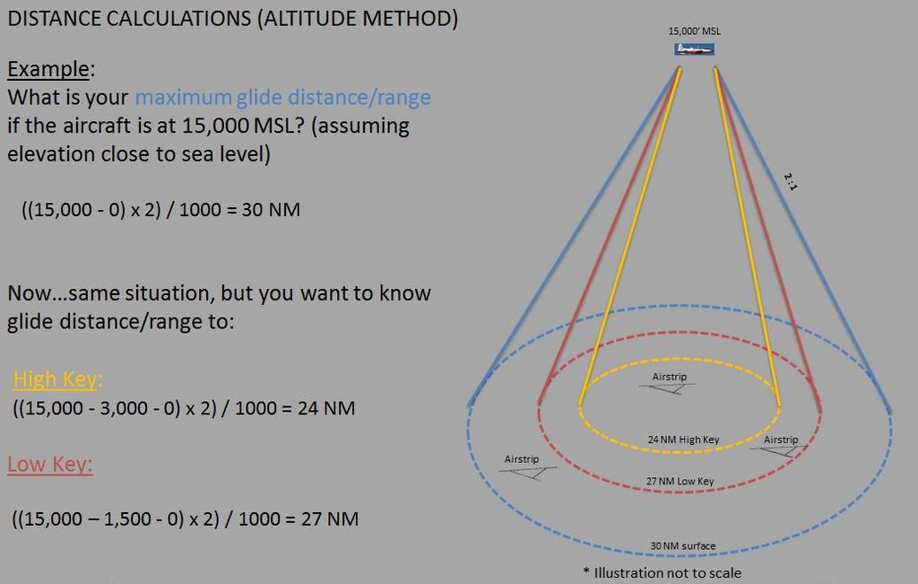
18 CHAPTER SEVEN Distance Calculations. A VFR chart, conventional NAVAIDS, and FMS NAV or TSD displays can be used when judging distance to the selected recovery airfield. The NRST function on the NAV and TSD FMS pages is extremely helpful in providing accurate distance information. Two primary methods used to determine energy state relative to emergency fields are: a. DME Method. Compare energy state relative to a specific field. A memory aid for this method is 1/2 DME + KEY+ Field Elevation. i. Determine distance to field using available resources. Distance to the airport displayed by the FMS is to the center point of the airfield and not to a specific runway. ii. iii. iv. Distance divided by 2, add Field Elevation; this equals minimum AGL altitude required to reach field. Is current altitude (AGL) sufficient to reach the field? Add 3,000 feet (high key) or 1,500 feet (low key) to AGL altitude required. v. Is energy sufficient to reach high or low key? b. Altitude Method. Compare energy state relative to more than one field. i. Subtract 3000 foot (high key) or 1500 foot (low key) from AGL altitude; multiply by 2 to determine maximum glide distance to high or low key. ii. iii. Identify fields within glide distance to high or low key. Determine most suitable field. Energy Management: Normally the ELP will be entered at high key, but the ELP can be intercepted at any point on the ELP profile between high key and final. Carefully manage energy to arrive at high key on altitude and airspeed. Attempt to dissipate excess energy prior to high key to minimize disorientation and allow the profile to be flown normally. If excess altitude exists during the glide to high key, lose energy by executing: 360 turns, bow ties, S-turns, slips, lower the gear early, extending the speed brake or use a combination of these methods. In a PEL situation, expeditiously maneuver towards high key while simultaneously dissipating energy as needed. All of these methods may be used for both PEL and Forced Landings at the pilot s discretion. 7-6 EMERGENCY PROCEDURES
19 CHAPTER SEVEN a. 360 turns prior to high key (PEL or Forced Landing). This is generally accomplished very near or directly over the intended landing destination. Approximate altitude loss for 360 turns: 125 KIAS, Idle power: 30 bank feet. 125 KIAS, 4-6% torque or prop feathered: 30 bank - 2,000 feet. 45 bank - 1,500 feet. 60 bank - 1,000 feet. b. Bow Ties. Bow Ties are essentially a continuous set of mild turns in the shape of a bow tie flown approximately ½ wing tip distance (WTD) away and on the downwind side of the landing area. With each bow tie, you should attempt to keep the landing runway in sight. Bow ties are not precise maneuvers and different techniques exist on how to fly them. Your instructor will provide guidance; however, plan to depart the bow ties for high key with sufficient altitude remaining to glide to high key altitude. c. Slips. A slip is an out-of-balance flight condition used to increase the sink rate and lose excess altitude while maintaining a constant airspeed and a specific track over the ground. Use caution slipping when configured and close to the ground. The slip must be taken out carefully with enough altitude remaining ( feet) to slow the rate of descent and ensure positive control of the aircraft during the final moments of the maneuver. Refer to Chapter 5 for slip procedures. d. S-turns. S-turns are used to affect a milder altitude loss and may be specifically used to make controlled corrections while proceeding direct to high key. Designed to increase the actual track over the ground, S-turns are simply lazy turns back and forth deviating from a straight-line ground track in order to provide more time to descend. e. Lower the gear early or extending the speed brake. In order to expedite entry into the ELP profile, lowering the gear early or extending the speed brake is a viable method to increase drag/descent rate during a high energy state while maneuvering to enter the ELP profile. Remember, your maximum glide distance changes if the engine fails with the gear down. Glide speed is ~105 KIAS with a sink rate of 1500 fpm and a glide ratio of ~1.6 nautical miles for every 1,000 feet of altitude lost. EMERGENCY PROCEDURES 7-7
 BASE KEY 600-800 feet AGL 120 KIAS Slowing to 110 KIAS(min) Gear Down Flaps LDG (as required) Perpendicular to landing line; halfway between low key and")
20 CHAPTER SEVEN POSITION ALTITUDE AIRSPEED CONFIG POSITION HIGH KEY feet AGL 120 KIAS Gear Down Flaps UP 1/3 down the runway Offset up to 1/4 WTD LOW KEY 1500 feet AGL Gear Down Flaps TO On runway heading 2/3 WTD (fuel cap on runway) BASE KEY feet AGL 120 KIAS Slowing to 110 KIAS(min) Gear Down Flaps LDG (as required) Perpendicular to landing line; halfway between low key and the runway FINAL Descending to land 110 KIAS Runway centerline Figure 7-1 Emergency Landing Pattern (ELP) Checkpoints 4. Emergency Landing Pattern Profile. The ELP profile is designed to position the aircraft for landing from a Forced Landing, PEL, or PEL from the pattern [PEL(P)] situation. See Figure 7-1 and Figure 7-2. Figure 7-2 Emergency Landing Pattern 7-8 EMERGENCY PROCEDURES
21 CHANGE 3 CHAPTER SEVEN a. Planning. The primary reference during an ELP is the runway. Crosscheck energy level (altitude + airspeed) with position. Look outside to maintain proper ground track. Predict energy level (altitude +airspeed) as early as possible at known reference points (high key, low key and base key) and anticipate required corrections. Position deviations can occur due to poor planning, imprecise aircraft control, or improper wind analysis. Trim throughout the ELP to minimize airspeed deviations. Make all corrections smooth and expeditious to avoid stall. b. High Key. Position the aircraft at high key, feet AGL, 120 KIAS, gear down, wings level, aligned with the landing direction and approximately one-quarter WTD from the runway away from the intended ELP turn direction. Turn, using angle of bank as necessary (~ in calm wind), towards the low key position. Maintain 120 KIAS and make appropriate voice call. c. Low Key. Located approximately two-thirds WTD (fuel cap on runway), abeam the intended point of landing (no wind), altitude approximately 1,500 feet AGL and 120 KIAS minimum. i. Approaching low key, crosscheck the runway to evaluate spacing. Check winds on PFD and crosscheck with windsock. Plan final approach accordingly. ii. At low key, level the wings momentarily and check for proper spacing and altitude. If energy is assessed to be adequate to make the runway, lower TO flaps (lower flaps no sooner than low key). If high energy state, lowering flaps to land will facilitate dissipating additional altitude or airspeed. d. Base Key. Maintain 120 KIAS minimum. The descent is normally greater than for a normal pattern. Fly the aircraft perpendicular to the runway (base key) at feet AGL. Altitude is not the only indication of proper energy management; the distance from the runway must also be assessed and the effect of winds taken into account. When landing is assured, flaps may be lowered to LDG. e. Final. Aircraft may be slowed to 110 KIAS (minimum) on final. Maintain 110 KIAS (minimum) on final until transition to landing. The transition to landing may begin well prior to the intended point of touch down. Plan to land within the first one-third of the runway. CAUTION Use caution with low power settings on final, especially with LDG flaps. High descent rate with idle power setting, coupled with pitch change to intercept a normal glide path, could result in rapid decrease in airspeed. A high sink rate can develop, which may result in a stall or hard landing. EMERGENCY PROCEDURES 7-9
22 CHAPTER SEVEN CHANGE 3 CAUTION At high density altitudes, engine response is delayed. When low and/or slow on final, engine spool time may not allow for a timely recovery prior to a hard landing. Pilots must not accept a low energy state inside of low key and any delay to initiate a waveoff may result in an excessive rate of descent. Exceeding NATOPS limits for rate of descent at touchdown can lead to structural damage and landing gear component failure. f. Landing. Adjust the nose attitude in the flare to transition to a normal landing. Touch down on the main gear and then gently lower the nose wheel as in a normal landing. Apply braking as needed based on runway remaining. i. PEL. If runway remaining after touchdown is insufficient to stop, waveoff. If sufficient power is available to obtain low key, attempt a PEL(P). If power is insufficient or engine failure occurs, consider ejection. NOTE If the aircraft is below profile between high key and low key, add power to regain altitude (if available). MAX power may not always be appropriate depending on the amount of correction required. After base key, use normal power corrections to ensure a safe and controlled landing. ii. Forced Landing. Anticipate a longer flare and touch down due to reduced drag. Use caution when applying brakes to prevent blown tires. If the aircraft cannot be stopped before the end of the runway, execute the Emergency Engine Shutdown on Ground Procedure or Eject. NOTE Do not delay the decision to Eject (actual engine failure) or waveoff (simulated engine failure) after determining a safe landing is unlikely. 5. ELP Wind Analysis. Winds can cause ELPs to differ significantly from standard. An uncorrected/unanticipated strong wind component can result in an unsuccessful ELP, even if it was otherwise flown flawlessly. a Determining Winds. Surface winds, winds at 1,000 to 3,000 feet, winds at 5,000 feet and winds aloft should be obtained from weather forecasts and serve as a good starting point for building situational awareness about actual wind conditions. The winds at 1,000 to 3,000 feet can vary significantly from surface winds and EMERGENCY PROCEDURES
23 CHANGE 3 CHAPTER SEVEN significantly alter required ELP ground track. At tower controlled runways, actual surface winds are known. Other methods to determine the winds include: i. Radio calls to other aircraft, a fixed base operator (FBO) on the field, ASOS, etc. ii. iii. iv. Without access to actual observations, use winds briefed by weather forecaster in the preflight briefing as a starting assumption. If performing an ELP at a non-towered airfield (NTA) without weather observation capability, assume that in the local area, surface winds will be similar to those at the home field. Observation of surface conditions; smoke, waves on lakes, wind tetrahedron, windsock, etc. v. Double the surface wind velocity to estimate winds at high key as wind is typically stronger at altitude than at the surface. vi. Use PFD indications of wind speed and direction PRECAUTIONARY EMERGENCY LANDING (PEL) 1. Description. Use the PEL procedure to ensure that a safe landing at a paved field can be made if indications of an impending engine failure should occur. 2. General. Indications of an impending engine failure could be excessive vibration, smoke or fumes, chip detector annunciator light, fuel or propeller malfunction or any other condition listed in the T-6B NATOPS Flight Manual requiring that you land as soon as possible via PEL. In most PEL situations (chip light, low oil pressure, etc.), time is the most critical element. The longer the engine runs, the greater the chance for complete failure. For this reason, every effort should be made utilizing energy management methods to safely expedite getting to high key with power. Don t turn a PEL into engine failure due to slow procedures or excessive troubleshooting! The PEL checklist in the T-6B NATOPS Flight Manual offers an organized approach to recovery with an impending engine malfunction. A good memory aid for these steps (PEL checklist); Turn, Climb, Clean, Check, BIP. 3. Procedures. The first three steps, Turn, Climb, Clean, must be executed nearly simultaneously and without delay. a. TURN. Turn in the general direction toward the nearest suitable field. Locate the field visually, use conventional NAVAIDS, FMS NAV/TSD displays, or FMS NRST EMERGENCY PROCEDURES 7-11
24 CHAPTER FIVE 2. General. A slip occurs when the aircraft slides sideways towards the center of the turn. It is caused by an insufficient amount of rudder in relation to the amount of aileron and the angle of bank used. If you roll into a turn without using coordinated rudder and aileron, or if you hold rudder against the turn after it has been established, the aircraft will slide sideways towards the center of the turn. A slip may also occur in straight-and-level flight if one wing is allowed to drag; that is, flying with one wing low, and holding the nose of the aircraft straight by the use of rudder pressure. In this case, the aircraft slips downward towards the earth s surface and loses altitude. In a full slip, the rate of descent may be in excess of 2000 feet per minute. 3. Procedures. a. Although the slip can be flown at any airspeed or configuration, it will normally be demonstrated and introduced at altitude simulating the slip to high key at 125 KIAS, clean configuration. Slips may also be demonstrated at 120 KIAS with gear down/flaps as required. NOTE Caution must be exercised, since stall speed is increased in this out-of-balance flight condition. b. To initiate a slip from wings level, lower one wing while applying opposite (top) rudder pressure. Select a reference point on the horizon and adjust rudder pressure and/or angle of bank to maintain the desired ground track. Full rudder deflection is not required during a slip. If full rudder deflection is used, remain below 150 KIAS. Use caution if electing to slip with gear down, especially low to the ground. c. To initiate a slip while in a turn, lower the inboard wing while increasing opposite (top) rudder pressure. It will be necessary to vary the angle of bank and rudder pressure to maintain the desired track over the ground. d. Monitor airspeed closely, adjust nose attitude as necessary to maintain 125 KIAS. Monitor the VSI and note increased rate of descent. NOTE The low-fuel warning light for the low-wing tank may illuminate regardless of fuel state. e. To recover from the slip, smoothly roll the wings towards level while reducing rudder pressure. Remember, the slip must be taken out with enough altitude remaining to slow the rate of descent and ensure positive control of the aircraft during the final moments of any maneuver in which it is used. FLIGHT PROCEDURES 5-29
25 Dead Engine Glide Distance (During PPEL/P) PPEL/P DEGA Calculation Based on 1:1 ratio (gear down) Every 1,000 of runway = 100 altitude req Using DEGA in pattern Still the Plan part of B.I.P. Use a bracket technique Anticipate level off and transition to descent Every 1,000 of runway is 100 of altitude req 2,100 MSL 1,850 MSL 100% torque climbs normally 18 deg nose high Cause to be high at LK Runway length has a large impact (example: Choctaw vs Barin) LK 1,600 MSL 5,000 Runway

26
27
28 Pattern PEL Energy Management Climb to DEGA 2000 AGL 1900 AGL 1800 AGL LOW KEY 1500 AGL 120 KIAS 1700 AGL 1600 AGL 130 KIAS 140 KIAS 150 KIAS 160 KIAS 170 KIAS Accelerate to DEGA KIAS = 100 Altitude = 1000 Runway
29 If you are unable to climb due to clouds or using the bottom of the Pelican working area as a hard deck during simulated PEL training MSL 240 KIAS 5500 MSL 125 KIAS X X Glide ~ 2 nm for every 1000 foot of altitude loss at best glide speed ~ 0.1 to 0.2 nm (~1000 feet) horizontal travel for every 10 knots above 125 KIAS X ~ 7.3 nm ISH start your deceleration HIGH KEY 3100 MSL ~ 2.3 nm Brewton X ~ 5 nm
Q3102 Briefing Guide (Worksheet)
") T-6B JPPT 1542.165A Simulator Event Briefing Guide Q3102 Briefing Guide (Worksheet) Planned Route: Takeoff: KNSE, Rwy 32 MOA Limits Altitude: South MOA or North MOA Route: Training Device: OFT SYLLABUS
T-6B JPPT 1542.165A Simulator Event Briefing Guide Q3102 Briefing Guide (Worksheet) Planned Route: Takeoff: KNSE, Rwy 32 MOA Limits Altitude: South MOA or North MOA Route: Training Device: OFT SYLLABUS
I2102 WORKSHEET. Planned Route: Takeoff: KNSE, RWY 32 Altitude: 12,000 Route: RADAR DEPARTURE. Syllabus Notes None. Special Syllabus Requirements None
 Planned Route: Takeoff: KNSE, RWY 32 Altitude: 12,000 Route: RADAR DEPARTURE Syllabus Notes None Special Syllabus Requirements None I2102 WORKSHEET Discuss a. IMC Emergencies NATOPS statement on sound
I2103 WORKSHEET. Planned Route: Takeoff: KNSE, RWY 32 Altitude: 12,000 Route: RADAR DEPARTURE. Syllabus Notes None
 Planned Route: Takeoff: KNSE, RWY 32 Altitude: 12,000 Route: RADAR DEPARTURE Syllabus Notes None I2103 WORKSHEET Special Syllabus Requirements Proceed direct to homefield using any available NAVAID. Discuss
Tecnam Eaglet Standard Operating Procedures and Maneuvers Supplement
 Tecnam Eaglet Standard Operating Procedures and Maneuvers Supplement Normal Takeoff Flaps Take Off Trim set Fuel pump on Check for traffic Line up on white stripe Full power Stick should be located in
Visualized Flight Maneuvers Handbook
 Visualized Flight Maneuvers Handbook For High Wing Aircraft Third Edition For Instructors and Students Aviation Supplies & Academics, Inc. Newcastle, Washington Visualized Flight Maneuvers Handbook for
NORMAL TAKEOFF AND CLIMB
 NORMAL TAKEOFF AND CLIMB CROSSWIND TAKEOFF AND CLIMB The normal takeoff is one in which the airplane is headed directly into the wind or the wind is very light, and the takeoff surface is firm with no
C2201 Briefing Guide (Worksheet)
") T-6B JPPT 1542.166A Simulator Event Briefing Guide C2201 Briefing Guide (Worksheet) Planned Route: Takeoff: KNSE, Rwy 05 Altitude: MOA Limits Route: North MOA Training Device: UTD / OFT SYLLABUS S: Introduce
T-6B JPPT 1542.166A Simulator Event Briefing Guide C2201 Briefing Guide (Worksheet) Planned Route: Takeoff: KNSE, Rwy 05 Altitude: MOA Limits Route: North MOA Training Device: UTD / OFT SYLLABUS S: Introduce
CIVIL AIR PATROL United States Air Force Auxiliary Cadet Program Directorate. Cessna 172 Maneuvers and Procedures
 CIVIL AIR PATROL United States Air Force Auxiliary Cadet Program Directorate Cessna 172 Maneuvers and Procedures This study guide is designed for the National Flight Academy Ground School. The information
C2103 Briefing Guide (Worksheet)
") T-6B JPPT 1542.166B Simulator Event Briefing Guide C2103 Briefing Guide (Worksheet) Planned Route: Takeoff: KNSE, Rwy 05 Altitude: MOA Limits Route: North MOA Training Device: UTD/OFT SYLLABUS S: Students
T-6B JPPT 1542.166B Simulator Event Briefing Guide C2103 Briefing Guide (Worksheet) Planned Route: Takeoff: KNSE, Rwy 05 Altitude: MOA Limits Route: North MOA Training Device: UTD/OFT SYLLABUS S: Students
See the diagrams at the end of this manual for judging position locations.
 Landing Events Penalties General Judges should use airport diagrams, satellite pictures or other means to determine, as accurately as possible, assessments of landing pattern penalties. Judges should be
Flight Profiles are designed as a guideline. Power settings are recommended and subject to change based
 MANEUVERS AND PROCEDURES Flight Profiles are designed as a guideline. Power settings are recommended and subject to change based upon actual conditions (i.e. aircraft weight, pressure altitude, icing conditions,
XI.C. Power-Off Stalls
 References: FAA-H-8083-3; POH/AFM Objectives Key Elements Elements Schedule Equipment IP s Actions SP s Actions Completion Standards The student should develop knowledge of stalls regarding aerodynamics,
MANEUVERS GUIDE. Liberty Aerospace 1383 General Aviation Drive Melbourne, FL (800)
") MANEUVERS GUIDE Liberty Aerospace 1383 General Aviation Drive Melbourne, FL 32935 (800) 759-5953 www.libertyaircraft.com Normal/Crosswind Takeoff and Climb 1. Complete the runup and before takeoff checklist.
MANEUVERS GUIDE Liberty Aerospace 1383 General Aviation Drive Melbourne, FL 32935 (800) 759-5953 www.libertyaircraft.com Normal/Crosswind Takeoff and Climb 1. Complete the runup and before takeoff checklist.
CESSNA 172-SP PRIVATE & COMMERCIAL COURSE
 CESSNA 172-SP PRIVATE & COMMERCIAL COURSE University of Dubuque INTENTIONALLY LEFT BLANK Revision 1 Standard Operating Procedures 1 CALLOUTS CONDITION Parking Brake Released After Takeoff Power has been
Cessna 152 Standardization Manual
 Cessna 152 Standardization Manual This manual is to be utilized in conjunction with the manufacturers approved POH/ AFM and the Airplane Flying Handbook (FAA-H-8083-3A). This manual should be used as a
C3101 Briefing Guide (Worksheet)
") T-6B JPPT 1542.165B Simulator Event Briefing Guide C3101 Briefing Guide (Worksheet) Planned Route: Takeoff: KNSE, Rwy 32 Altitude: Working area limits Route: NMOA or Pelican, Brewton or Evergreen, KNSE
T-6B JPPT 1542.165B Simulator Event Briefing Guide C3101 Briefing Guide (Worksheet) Planned Route: Takeoff: KNSE, Rwy 32 Altitude: Working area limits Route: NMOA or Pelican, Brewton or Evergreen, KNSE
Single Engine Complex Training Supplement PA28R-201 Piper Arrow III (Spring 2016 Revision)
") Single Engine Complex Training Supplement PA28R-201 Piper Arrow III (Spring 2016 Revision) V-speed Quick Reference V-Speed KIAS Description Airspeed Indicator Marking VSO 55 Stall speed in landing configuration
Single Engine Complex Training Supplement PA28R-201 Piper Arrow III (Spring 2016 Revision) V-speed Quick Reference V-Speed KIAS Description Airspeed Indicator Marking VSO 55 Stall speed in landing configuration
PROCEDURES GUIDE CESSNA 172N SKYHAWK
 PROCEDURES GUIDE CESSNA 172N SKYHAWK THESE PROCEDURES ARE DESIGNED TO PROVIDE STANDARDIZED METHODS UNDER NORMAL CONDITIONS. AS CONDITIONS CHANGE, THE PROCEDURES WILL NEED TO BE ADJUSTED. PASSENGER BRIEFING
NORMAL TAKEOFF PILOT TRAINING MANUAL KING AIR 200 SERIES OF AIRCRAFT
 NORMAL TAKEOFF Climb-Out 1. Accelerate to 160 KIAS 2. Landing/Taxi lights: Out 3. Climb Checklist complete 1. 160 KIAS up to 10,000 ft 2. Decrease 2 KIAS per 1,000 ft above 10,000 ft to 130 KIAS at 25,000
PROCEDURES GUIDE. FLIGHT MANEUVERS for the SPORT PILOT
 Page 1 of 10 PROCEDURES GUIDE FLIGHT MANEUVERS for the SPORT PILOT * Author s Note: Whereas this procedures guide has been written for a specific application, it can easily be modified to fit many different
Piper PA Seminole 1. Standardization Manual
 Piper PA-44-180 Seminole Standardization Manual This manual is to be utilized in conjunction with the manufacturers approved POH/AFM and the Airplane Flying Handbook (FAA-H-8083-3A). This manual should
Beechcraft Duchess 76 Maneuver Notes
 Beechcraft Duchess 76 Maneuver Notes I. Maneuver notes for Performance (AOA V), Slow Flight and Stalls (AOA VIII), Emergency Operations (AOA X), and Multiengine Operations (AOA XI) a. Maneuvers addressed:
Cessna 172S Skyhawk Standardization Manual
 Cessna 172S Skyhawk Standardization Manual This manual is to be utilized in conjunction with the manufacturers approved POH/ AFM and the Airplane Flying Handbook (FAA-H-8083-3A). This manual should be
XI.B. Power-On Stalls
 XI.B. Power-On Stalls References: AC 61-67; FAA-H-8083-3; POH/AFM Objectives Key Elements Elements Schedule Equipment IP s Actions SP s Actions Completion Standards The student should develop knowledge
VI.B. Traffic Patterns
 References: FAA-H-8083-3; FAA-H-8083-25; AC 90-42; AC90-66; AIM Objectives Key Elements Elements Schedule Equipment IP s Actions SP s Actions Completion Standards The student should develop knowledge of
Guidance Notes PRIVATE AND COMMERCIAL PILOT TRAINING
 PRIVATE AND COMMERCIAL PILOT TRAINING September 2005 1 st Edition ACKNOWLEDGEMENT Transport Canada thanks the Federal Aviation Administration of the United States for their permission to use the chapter
PERFORMANCE MANEUVERS
 Ch 09.qxd 5/7/04 8:14 AM Page 9-1 PERFORMANCE MANEUVERS Performance maneuvers are used to develop a high degree of pilot skill. They aid the pilot in analyzing the forces acting on the airplane and in
VFR Circuit Tutorial. A Hong Kong-based Virtual Airline. VOHK Training Team Version 2.1 Flight Simulation Use Only 9 July 2017
 A Hong Kong-based Virtual Airline VFR Circuit Tutorial VOHK Training Team Version 2.1 Flight Simulation Use Only 9 July 2017 Copyright 2017 Oasis Hong Kong Virtual Page 1 Oasis Hong Kong Virtual (VOHK)
IVAO International Virtual Aviation Organization Training department
 1 Introduction IVAO International Virtual Aviation Organization Training department TRAFFIC PATTERN DESCRIPTION An aerodrome traffic pattern is used by VFR traffic for training purpose or to prepare the
Climbs, descents, turns, and stalls These are some of the maneuvers you'll practice, and practice, and practice By David Montoya
 Climbs, descents, turns, and stalls These are some of the maneuvers you'll practice, and practice, and practice By David Montoya Air work stalls, steep turns, climbs, descents, slow flight is the one element
VII.H. Go-Around/Rejected Landing
 VII.H. Go-Around/Rejected Landing References: FAA-H-8083-3; POH/AFM Objectives Key Elements Elements Schedule Equipment IP s Actions SP s Actions Completion Standards The student should develop knowledge
FAA-S-ACS-6 June 2016 Private Pilot Airplane Airman Certification Standards. Task ACS Settings
 FAA-S-ACS-6 June 2016 Private Pilot Airplane Airman Certification Standards Cessna 172: mixture rich, carb heat out if below the green arc. Clearing Turns all manuevers! Task ACS Settings Traffic Pattern
CAP-USAF FLIGHT MANEUVERS GUIDE
 CAP-USAF FLIGHT MANEUVERS GUIDE February 2012 Flight Maneuvers Guide This guide describes and standardizes the instruction and performance of the various flight maneuvers described in Chapter 3 of AFI11-2CAP-USAF,
Q2101 Briefing Guide (Worksheet)
") T-6B JPPT 1542.165A Simulator Event Briefing Guide Q2101 Briefing Guide (Worksheet) Planned Route: Takeoff: KNSE, Rwy 05 Altitude: MOA Limits Route: North MOA Training Device: UTD/OFT IUT NATOP flights
T-6B JPPT 1542.165A Simulator Event Briefing Guide Q2101 Briefing Guide (Worksheet) Planned Route: Takeoff: KNSE, Rwy 05 Altitude: MOA Limits Route: North MOA Training Device: UTD/OFT IUT NATOP flights
POWER-OFF 180 ACCURACY APPROACH AND LANDING
 POWER-OFF 180 ACCURACY APPROACH AND LANDING OBJECTIVE To teach the commercial student the knowledge of the elements related to a power-off 180 accuracy approach and landing. COMPLETION STANDARDS 1. Considers
Mountain Fury Mountain Search Flying Course Syllabus Fourth Sortie : High Altitude Search
 Mountain Fury Mountain Search Flying Course Syllabus Fourth Sortie : High Altitude Search Objectives 1. Develop trainee's proficiency in planning and execution of mountain search sorties. 2. Develop trainee's
OFFICE HOURS Monday through Friday, 7:30 a.m. to 4:30 p.m., Pacific Time. Lunch hour is 11:30 a.m. to 12:30 p.m.
 Robinson Helicopter Company Phone: (310) 539-0508 2901 Airport Drive Fax: (310) 539-5198 Torrance, California 90505-6115 Web: www.robinsonheli.com United States of America OFFICE HOURS Monday through Friday,
C2201 Briefing Guide (Worksheet)
") T-6B JPPT 1542.166B Simulator Event Briefing Guide C2201 Briefing Guide (Worksheet) Planned Route: Takeoff: KNSE, Rwy 05 Altitude: MOA Limits Route: North MOA Training Device: UTD / OFT SYLLABUS S: Introduce
T-6B JPPT 1542.166B Simulator Event Briefing Guide C2201 Briefing Guide (Worksheet) Planned Route: Takeoff: KNSE, Rwy 05 Altitude: MOA Limits Route: North MOA Training Device: UTD / OFT SYLLABUS S: Introduce
Compiled by Matt Zagoren
 The information provided in this document is to be used during simulated flight only and is not intended to be used in real life. Attention VA's - you may post this file on your site for download. Please
C3301 Briefing Guide (Worksheet)
") T-6B JPPT 1542.166B Simulator Event Briefing Guide C3301 Briefing Guide (Worksheet) Planned Route: Takeoff: Altitude: Route: Training Device: KNSE, Runway 32 VFR to North 5500' MSL KNSE, Brewton or Evergreen
T-6B JPPT 1542.166B Simulator Event Briefing Guide C3301 Briefing Guide (Worksheet) Planned Route: Takeoff: Altitude: Route: Training Device: KNSE, Runway 32 VFR to North 5500' MSL KNSE, Brewton or Evergreen
Commercial Maneuvers for PA28RT-201
 Commercial Maneuvers for PA28RT-201 Cruise checklist: Power 23'', 2400 RPM (23, 24) Lean mixture Fuel Pump Off (Check positive fuel pressure) Landing light Off Pre-Maneuver Checklist in the Takeoff configuration
Cessna 172R Profiles
 Cessna 172R Profiles TRAFFIC PATTERNS (Verify pattern altitude) Start your first climbing turn within 300' of pattern altitude Enter 45 degree angle to the downwind leg Depart the traffic pattern straight-out,
Mountain Fury Mountain Search Flying Course Syllabus
 Mountain Fury Mountain Search Flying Course Syllabus Goals 1. Pilots who complete this program will be able to perform with precision and confidence all of the tasks and flight maneuvers required for safe
ILS APPROACH WITH A320
 1. Introduction ILS APPROACH WITH A320 This document presents an example of an Instrument landing system (ILS) approach performed with an Airbus 320 at LFBO airport runway 32 left. This document does not
XI.D. Crossed-Control Stalls
 References: FAA-H-8083-3; POH/AFM Objectives Key Elements Elements Schedule Equipment IP s Actions SP s Actions Completion Standards The student should understand the dynamics of a crossed-control stall
Normal T/O Procedure. Short Field T/O Procedure
 Normal T/O Procedure Add full power: Engine Instruments green Airspeed alive 1,000 AGL Accelerate to enroute climb 85 KIAS Complete climb check Vr = 55-60 Vy 79 KIAS Prior to Receiving T/O Clearance Complete
Discuss: 1. Instrument Flight Checklist
 INST 1 Prerequisites: 1. OFT: Tac 1 2. CBT: Basic Instrument Flight, IFR Navigation I & II Lessons P2 501, P2 502, & P2 503. Discuss: 1. Instrument Flight Checklist NATOPS 13.1.3 Instrument Flight Checklist
VI.B. Traffic Patterns
 References: FAA-H-8083-3; FAA-H-8083-25; AC 90-42; AC90-66; AIM Objectives Key Elements Elements Schedule Equipment IP s Actions SP s Actions Completion Standards The student should develop knowledge of
Jabiru J230-SP Section 10
 Jabiru J230-SP Section 10 Section 10 10.1 Introduction This section contains information on the basic flight controls, door operation, and entry and egress, followed by a flight training outline compiled
C3301 Briefing Guide (Worksheet)
") T-6B JPPT 1542.166A CH-2 Simulator Event Briefing Guide C3301 Briefing Guide (Worksheet) Planned Route: Takeoff: Altitude: Route: Training Device: KNSE, Runway 32 VFR to North 5500' MSL KNSE, Brewton or
T-6B JPPT 1542.166A CH-2 Simulator Event Briefing Guide C3301 Briefing Guide (Worksheet) Planned Route: Takeoff: Altitude: Route: Training Device: KNSE, Runway 32 VFR to North 5500' MSL KNSE, Brewton or
OFFICE HOURS Monday through Friday, 7:30 a.m. to 4:30 p.m., Pacific Time. Lunch hour is 11:30 a.m. to 12:30 p.m.
 Robinson Helicopter Company Phone: (310) 539-0508 2901 Airport Drive Fax: (310) 539-5198 Torrance, California 90505-6115 Web: www.robinsonheli.com United States of America OFFICE HOURS Monday through Friday,
Circuit Considerations
 Circuit Training Circuit Considerations This briefing deals with those aspects of a normal circuit that were deferred during Circuit Introduction, to avoid student overload. Objectives To continue circuit
FFI Formation Guidelines and Standard Procedures Mooney Supplement (28 Dec, 2018; Rev 12)
") FFI Formation Guidelines and Standard Procedures Mooney Supplement (28 Dec, 2018; Rev 12) This document describes formation flight differences between RV and Mooney aircraft. In conjunction with the FFI
FFI Formation Guidelines and Standard Procedures Mooney Supplement (28 Dec, 2018; Rev 12) This document describes formation flight differences between RV and Mooney aircraft. In conjunction with the FFI
Flying The. Traffic Pattern. Skill Level: Basic
 Flying The Now that you ve mastered a number of basic and intermediate flying skills, it s time to put them all to the test in the exercise that combines them all Flying The Traffic Pattern. In this Flight
I2201 WORKSHEET. Planned Route: Takeoff: KSAT, RWY 31R Altitude: 6,000 Route: KRND via Radar vectors RND KSAT Airport Diagram
 I2201 WORKSHEET Planned Route: Takeoff: KSAT, RWY 31R Altitude: 6,000 Route: KRND via Radar vectors RND KSAT Airport Diagram Syllabus Notes None Special Syllabus Requirements None Discuss a. HSI orientation
VII.E. Normal and Crosswind Approach and Landing
 References: FAA-H-8083-3; POH/AFM Objectives Key Elements Elements Schedule Equipment IP s Actions SP s Actions Completion Standards The student should be able to perform a normal approach and landing
CHAPTER 8 MANEUVERS TABLE OF CONTENTS
 CHAPTER 8 MANEUVERS TABLE OF CONTENTS Transition Airspeeds... 3 Checklists and callouts during maneuvers... 3 Guidance to better maneuver execution... 3 Taxiing... 5 Pre-Maneuver Checklist... 6 Clearing
I2101 SIMULATOR ABBREVIATED CHECKLIST
 WORKSHEET I2101 SIMULATOR ABBREVIATED CHECKLIST Planned Route: Takeoff: KNSE, RWY 32 Altitude: 12,000 Route: PENSACOLA NORTH MOA Special Syllabus Requirements: -None Discuss Items a. Departures Four basic
Cessna 172 Profiles. TRAFFIC PATTERNS (Check Chart Supplement prior to flight) Index
 Index") Cessna 172 Profiles TRAFFIC PATTERNS (Check Chart Supplement prior to flight) Index When Cleared for Takeoff - Landing/Taxi lights ON Mixture-As Required Power-Check Takeoff RPM Power Climb at Vy Start
Cessna 172 Profiles TRAFFIC PATTERNS (Check Chart Supplement prior to flight) Index When Cleared for Takeoff - Landing/Taxi lights ON Mixture-As Required Power-Check Takeoff RPM Power Climb at Vy Start
XII.A-D. Basic Attitude Instrument Flight
 References: FAA-H-8083-3; FAA-8083-3-15 Objectives Key Elements Elements Schedule Equipment IP s Actions SP s Actions Completion Standards The student should develop knowledge of the elements related to
C-182P MANEUVERS GUIDE TABLE OF CONTENTS
 INTRODUCTION The following maneuver guide is designed to provide a technique for completing each VFR maneuver required by the FAA s Practical Test Standards for the Private Practical Test. By performing
C-182P MANEUVERS GUIDE TABLE OF CONTENTS
 INTRODUCTION The following maneuver guide is designed to provide a technique for completing each VFR maneuver required by the FAA s Practical Test Standards for the Private Practical Test. By performing
Noise Abatement Takeoff 1 Close In Profile
 PF Duties Captain: Advance thrust to 70% N1 (Allow Engines to stabilize) Noise Abatement Takeoff 1 Close In Profile Flaps Increase Speed to Vref 30 +80kts Climb Checklist Push N1 Button to set Takeoff
Front Cover Picture Mark Rasmussen - Fotolia.com
 Flight Maneuvers And Stick and Rudder Skills A complete learn to fly handbook by one of aviation s most knowledgeable and experienced flight instructors Front Cover Picture Mark Rasmussen - Fotolia.com
Climbing and Descending
 Basic Concepts Climbing and Descending This lesson builds on the coordination skills learnt in the previous lesson, Straight and Level. Check with the student what the important elements of the last lesson
Low Flying Introduction
 Advanced Manoeuvres Low Flying Introduction Commonly, low flying refers to any flight at or below 500 feet agl that may be practised only in designated low flying zones. By maintaining good situational
TAILWHEEL AIRPLANES LANDING GEAR TAXIING
 Ch 13.qxd 5/7/04 10:04 AM Page 13-1 TAILWHEEL AIRPLANES Tailwheel airplanes are often referred to as conventional gear airplanes. Due to their design and structure, tailwheel airplanes exhibit operational
VI.A-E. Basic Attitude Instrument Flight
 References: FAA-H-8083-3; FAA-8083-3-15 Objectives Key Elements Elements Schedule Equipment IP s Actions SP s Actions Completion Standards The student should develop knowledge of the elements related to
Bonanza/Debonair Pilots
 Bonanza/Debonair Pilots Completing this worksheet is a great way to reinforce the proper speeds for operating your Bonanza or Debonair under varying operating conditions, and to understand the changes
C-130 Reduction in Directional Stability at Low Dynamic Pressure and High Power Settings
 C-130 Reduction in Directional Stability at Low Dynamic Pressure and High Power Settings The C-130 experiences a marked reduction of directional stability at low dynamic pressures, high power settings,
Medium, Climbing and Descending Turns
 Basic Concepts Medium, Climbing and Descending Turns A medium turn is defined as a turn using up to 30 degrees angle of bank. Climbing and descending turns are combined with medium turns within this briefing,
To learn how to recognize and recover from a loss of directional control caused by an asymmetrical thrust condition at low airspeed.
 V MC Demonstration Area XIV, Task E Revised 2015-08-13 Objective To learn how to recognize and recover from a loss of directional control caused by an asymmetrical thrust condition at low airspeed. Elements
SUPPLEMENT SEPTEMBER 2010 HIGH ALTITUDE TAKEOFF AND LANDING (ABOVE 14,000 FEET PRESSURE ALTITUDE) MODEL AND ON 68FM-S28-00 S28-1
 MODEL AND ON 68FM-S28-00 S28-1") MODEL 680 680-0001 AND ON HIGH ALTITUDE TAKEOFF AND LANDING (ABOVE 14,000 FEET PRESSURE ALTITUDE) COPYRIGHT 2010 CESSNA AIRCRAFT COMPANY WICHITA, KANSAS, USA 15 SEPTEMBER 2010 S28-1 SECTION V - SUPPLEMENTS
MODEL 680 680-0001 AND ON HIGH ALTITUDE TAKEOFF AND LANDING (ABOVE 14,000 FEET PRESSURE ALTITUDE) COPYRIGHT 2010 CESSNA AIRCRAFT COMPANY WICHITA, KANSAS, USA 15 SEPTEMBER 2010 S28-1 SECTION V - SUPPLEMENTS
Aviation Merit Badge Knowledge Check
 Aviation Merit Badge Knowledge Check Name: Troop: Location: Test Score: Total: Each question is worth 2.5 points. 70% is passing Dan Beard Council Aviation Knowledge Check 1 Question 1: The upward acting
COASTAL SOARING ASSOCIATION, INC. STANDARD OPERATING PROCEDURES Revised 09/17/2010
 A. General COASTAL SOARING ASSOCIATION, INC. STANDARD OPERATING PROCEDURES Revised 09/17/2010 1. The sailplane s canopy shall normally be kept closed and the spoilers open whenever the cockpit is unoccupied
Gleim Private Pilot Flight Maneuvers Seventh Edition, 1st Printing Updates February 2018
 Page 1 of 11 Gleim Private Pilot Flight Maneuvers Seventh Edition, 1st Printing Updates February 2018 If you are tested on any content not represented in our materials or this update, please share this
Flying The Boeing Advanced
 Flying The Boeing 727-200 Advanced This section includes Pilot s Operating Handbook and Checklists. The POH section is first, followed by the Checklists. FOM: This section includes performance data on
NSRCA Club or Novice Class. Maneuver Descriptions. And. Suggested Downgrades
 NSRCA Club or Novice Class Maneuver Descriptions And Suggested Downgrades August 18, 2016 Purpose: The purpose of this guide is to furnish an accurate description of each maneuver of the NSRCA Club or
II.E. Airplane Flight Controls
 References: FAA-H-8083-3; FAA-8083-3-25 Objectives Key Elements Elements Schedule Equipment IP s Actions SP s Actions Completion Standards The student should develop knowledge of the elements related to
General. Procedure Checklists. Emergency Procedures. FSD Aerostar 700P Superstar
 General The recommended procedures for coping with various types of emergencies and critical situations are provided in this section. These procedures are suggested as a course of action for coping with
Pre Solo Written For Schweizer 2-33 Glider. Eagles Sport Aviation Club
 Pre Solo Written For Schweizer 2-33 Glider Eagles Sport Aviation Club Student Date: Instructor 1) What is the maximum gross weight for the 2-33? Empty Weight? 2) What position should the trim level be
Civil Air Patrol Auxiliary of the United States Air Force
 Mountain Flying Qualification Course Civil Air Patrol Auxiliary of the United States Air Force Mountain Flying Flying in Mountain Winds Determine direction and velocity of steady winds by observing dust,
NIFA CRM / LOFT CONTESTANT BRIEFING
 NIFA CRM / LOFT CONTESTANT BRIEFING You are the aircrew for a large corporation s Part 91 flight department. The flight you are conducting, like all the company s operations, is extremely time sensitive.
SR22 Airplane Flight Manual (AFM) Temporary Change
 Temporary Change") Cirrus Design TPOH AFM Temporary Change Airplane Flight Manual (AFM) Temporary Change Information in this Temporary Change adds to, supersedes, or deletes information in the basic Pilot s Operating Handbook.
Cirrus Design TPOH AFM Temporary Change Airplane Flight Manual (AFM) Temporary Change Information in this Temporary Change adds to, supersedes, or deletes information in the basic Pilot s Operating Handbook.
Sportsman (401) Maneuver Descriptions. And. Suggested Downgrades
 Maneuver Descriptions. And. Suggested Downgrades") Sportsman (401) Maneuver Descriptions And Suggested Downgrades 2015 Purpose: The purpose of this guide is to furnish an accurate description of each maneuver of the Sportsman (401) pattern sequence. Study
Sportsman (401) Maneuver Descriptions And Suggested Downgrades 2015 Purpose: The purpose of this guide is to furnish an accurate description of each maneuver of the Sportsman (401) pattern sequence. Study
Basic Mountain Flying
 Advanced Manoeuvres Basic Mountain Flying This training introduces students to the principles of basic mountain flying and further develops their experience and understanding of operating near terrain
 interaction of the aircraft with the given wind conditions and power changes. This will aid in timing the descent for touchdown. During the landing, as the aircraft nears the deck for touchdown, the pilot
Spin Training. Bob Wander Soaring Books & Supplies Website:
 Spin Training Bob Wander Soaring Books & Supplies Website: www.bobwander.com E-Mail: Soarbooks@aol.com This Presentation Is Based On A Chapter In: Why Is Spin Training Important? Spins have been with us
Accident Prevention Program
 Accident Prevention Program Wind Shear "Tonto 55, final controller, how do you read...?" "55, loud and clear." This has been a good flight thought the Instructor Pilot (IP) as the pilot in front smoothly
Stalls and Spins. Tom Johnson CFIG
 Stalls and Spins Tom Johnson CFIG Contents Angle of Attack Stall Recognition and Recovery Spin Entry and Recovery Load Limit Considerations Gust Induced Stall and Spin Accidents Stalls a stall is a loss
Maximum Rate Turns. Objective To carry out a balanced, maximum rate, level turn using full power.
 Advanced Manoeuvres Maximum Rate Turns To achieve the maximum rate of turn, the greatest possible force toward the centre of the turn is required. This is achieved by inclining the lift vector as far as
X.B. S-Turns. References: FAA-H The student should develop knowledge of the elements related to S-turns as necessary in the Private Pilot PTS.
 References: FAA-H-8083-3 Objectives Key Elements Elements Schedule Equipment IP s Actions SP s Actions Completion Standards The student should develop knowledge of the elements related to S-turns as necessary
Circuit Introduction. Considerations. Circuit Training
 Circuit Training Circuit Introduction The circuit is an orderly pattern used to position the aeroplane for landing and minimise the risk of collision with other aircraft. Airfields attract aircraft, therefore
Advanced Stalling. L = CL ½ ρ V 2 S. L = angle of attack x airspeed. h L = angle of attack x h airspeed. Advanced Manoeuvres
 Advanced Manoeuvres Advanced Stalling This Advanced Stalling lesson covers the factors that affect the observed airspeed and nose attitude at the stall. Although the aeroplane always stalls when the aerofoil
VIII.A. Straight and Level Flight
 VIII.A. Straight and Level Flight References: FAA-H-8083-3; FAA-H-8083-25 Objectives Key Elements Elements Schedule Equipment IP s Actions SP s Actions Completion Standards The student should develop the
Straight and Level. Basic Concepts. Figure 1
 Basic Concepts Straight and Level This lesson should start with you asking the student what they did in the last lesson, what do they remember, and determining if they have remembered correctly. We must
TERMS AND DEFINITIONS
 Ch 05.qxd 5/7/04 7:02 AM Page 5-1 GENERAL This chapter discusses takeoffs and departure climbs in tricycle landing gear (nosewheel-type) airplanes under normal conditions, and under conditions which require
ABS/BPPP Performance Worksheet: Baron/Travel Air Pilots
 ABS/BPPP Performance Worksheet: Baron/Travel Air Pilots This worksheet is the homework for BPPP Initial pilots to complete before their BPPP flight. It s designed to help the pilot develop a deep understanding
Engine Failure after Takeoff
 Circuit Training Engine Failure after Takeoff Although engine failure in modern aeroplanes is quite rare, the takeoff phase incorporates all the worst aspects of this type of emergency. The aeroplane is
FLIGHT AT MINIMUM CONTROLLABLE AIRSPEED
 INTRODUCTION The maintenance of lift and control of an airplane in flight requires a certain minimum airspeed. This critical airspeed depends on certain factors, such as gross weight, load factors, and