Report for the Submission of Data Supporting World Record Runs in the Dead Downwind Vehicle Category
|
|
|
- Neil Hood
- 5 years ago
- Views:
Transcription
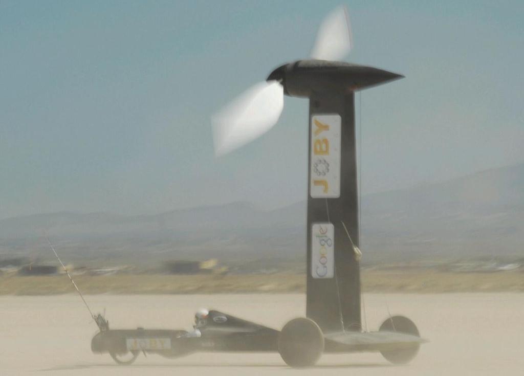
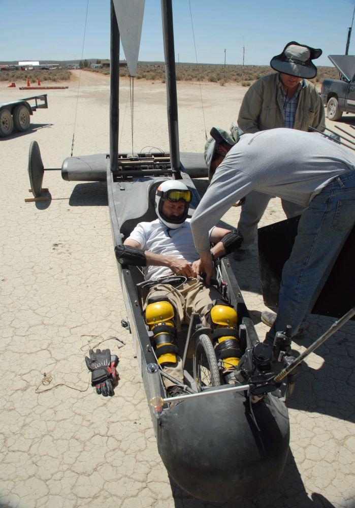
1 Report for the Submission of Data Supporting World Record Runs in the Dead Downwind Vehicle Category Prepared by Rick Cavallaro 12 July 2010 Introduction On the 2 nd and 3 rd of July 2010, the ThinAir Designs team made several runs with the wind powered vehicle, the Blackbird, on the El Mirage dry lake bed in southern California. This was done in a bid to establish the first world records in the newly developed NALSA categories C3 and C4 (top speed for a nonconventional sailing craft and greatest ratio of vehicle speed to wind speed for a dead downwind vehicle). This document summarizes the case for a vehicle speed ratio of 2.8 times the wind speed and a top vehicle speed of 51.4 mph in accordance with categories C4 and C3, respectively. Bob Dill of NALSA is in possession of all raw data logged from multiple sensors on multiple vehicles and platforms that will support this summary. Vehicle Description The Blackbird is a vehicle designed and built with the sole purpose of traveling directly downwind, faster than the wind, powered only by the wind, steady state. It has a tricycle configuration and a 17.5 diameter propeller on the top of a set of pylons over the vehicle s rear axle. The propeller is connected to the rear axle through a simple chain-drive transmission and ratchets. This configuration permits the wheels to turn the propeller via the fixed ratio transmission, while allowing the prop to freewheel during braking. The prop pitch can be controlled by the pilot on the fly. By design, such a configuration cannot be accelerated through the use of stored energy/momentum. The vehicle makes no use of any controls or actuators other than those operated directly by the pilot with human power.
2
3
4 Analysis of speed run for NALSA category C3 On 2 July 2010 the DDWFTTW craft reached a top speed of 51.4 mph at 14:19:16 PDT on El Mirage dry lake. This speed is a three-second average from GPS-Dill-#7 which was attached by Bob Dill to the front deck of the DDWFTTW craft. Secondary measurements were made from the chase vehicle which had three logging GPS receivers (including NALSA provided GPS-Dill-#5 and GPS-DILL-#6) and a MetOne Instruments anemometer. Chart 1 below shows the DDWFTTW vehicle speed profile for the submitted time period. Time is presented on the horizontal axis, and represents UTC time in seconds from beginning of day. Speed is given on the vertical axis in knots. Chart 1: DW Cart speed in knots as measured by GPS-Dill-#7 Analysis of 10 second run for NALSA category C4 The subject run begins from a dead stop at seconds (GPS time in seconds measured from beginning of week). The downwind cart is pushed on foot (by JB) and released at at a ground speed of 11 mph. From this point the DW cart accelerates monotonically, by wind power alone, up to and through the 10 second measurement period from to During this period, the DW cart achieved a 10-second average speed of mph while the wind had a 10-second average speed of mph.
5 During this period the DW cart maintained a 10-second averaged heading within less than 5 degrees of the 10-second average of the true wind direction. Over this same period, the DW cart averaged a 2.77 multiple of true wind speed, while it s absolute speed increased from mph to mph. Charts 2, 3, and 4 detail the performance of this run. In each case, time is given on the horizontal axis as GPS time in seconds from beginning of week. The curves on the chart are as follows: Red 10-second averaged cart speed (mph) Yellow Non-averaged cart speed (mph) Blue 10-second averaged cart heading (deg.; 0: East; 90: North) Black 10-second averaged wind TO direction (deg.; 0: East; 90: North) Green 10-second averaged speed ratio (cart speed / wind speed) Chart 2: Overview of data supporting submission in record category C4

6 Chart 3: Measurement period data supporting submission in record category C4 Chart 4: Speed ratio data during 10 second measurement period
7 Chart 5: Distance in feet between chase vehicle and downwind vehicle during 10 second measurement period (blue curve) Chart 6: True wind speed (mph) measured at chase vehicle during 10 second measurement period
8 Attendees: Representing ThinAir Designs: Rick Cavallaro: Vehicle designer, builder, and driver John Borton: Vehicle designer and builder Steve Morris: Aerodynamics consultant Chris Fields: SJSU student contributor Representing NALSA as official observers: Bob Dill: NALSA secretary Kimball Livingston: Editor of SAIL magazine Others on site included Richard Jenkins (world land speed sailing record holder), four engineers representing Joby Energy (primary sponsor of the Blackbird), David Glover (independent photographer/videographer), and several others who had been following the project.
9 Appendix 1 Analysis demonstrating that the vehicle is capable of DDWFTTW In order to run in this NALSA category it must be demonstrated that the vehicle is capable of going directly downwind, faster than the wind, powered only by the wind, steady state. While this has been a hotly debated topic on the internet, the principle has been demonstrated many times with working models and has been analyzed both by the ThinAir Designs team as well as by noted aerodynamicist Mark Drela. See Drela Power Analysis.pdf and Drela DDWFTTW Analysis.pdf The following case study will demonstrate the principle in simple terms: Consider a cart with an electric generator driven by the rear axle and a propeller driven by an electric motor. We ll assume the following reasonable set of parameters: Electric generator efficiency: 85% Electric motor efficiency: 85% Propeller efficiency: 85% Coefficient of rolling resistance: 0.02 Vehicle gross weight: 650 lbs Coefficient of aerodynamic drag: 0.3 Projected frontal area: 20 sq-ft For the purpose of this analysis we won t consider the issue of accelerating to speed, but rather the cart s ability to maintain faster-than-the-wind speed and further accelerate from that point. Thus we ll tow the vehicle up to a speed of 20 mph in a 15 mph tail-wind and then let it loose. In this situation the vehicle will experience a relative head-wind of 5 mph. We ll adjust the generator output such that it produces 20 lbs of retarding force at the wheels. This tells us the wheels will be putting power into the generator at a rate of 20 mph x 20 lbs (400 mphlbs). But the generator will only produce 340 mph-lbs due to its 85% efficiency. We deliver that power to the electric motor. But we get only 289 mph-lbs at the motor's shaft due to the motor's 85% efficiency. This power is working to spin the propeller, but the propeller does only 245 mph-lbs of work on the air due to its 85% efficiency. Given the vehicle s relative airspeed of 5 mph, we can see that the prop will be producing 49 lbs of thrust. Given our vehicle gross weight of 650 lbs and coefficient of rolling resistance of 0.02, we can calculate that we ll lose 13 lbs of thrust to rolling resistance. We lose another 20 lbs at the wheels due to the retarding force caused by the electric generator. This leaves us with an excess of 16 lbs ( ).
10 Finally, we have to consider the aerodynamic drag we experience in this state: Aero_drag = Drag_coeff * frontal_area * ½ * rho * Vel * Vel In which rho is air density and vel is the relative air velocity experienced by the vehicle. Aero_drag = 0.3 * 20 * ½ * * * = lbs Where is the air density in slugs/ft^3 and is our velocity in ft/sec. Subtracting our aero drag of lbs from our excess thrust of 16 lbs, gives us a remaining excess thrust of 15.6 lbs. This shows that the vehicle will continue to accelerate from this state. The simple explanation is that the vehicle acts as a lever between two media (the ground and the air). Like any lever we can trade a small force over a large distance for a larger force over a smaller distance. This is how we get more thrust from the prop than we create drag at the wheels (since the wheels are moving over the ground faster than the prop is moving through the air due to the tailwind). Appendix 2 Proof that the vehicle performs best Dead Downwind As can readily be seen from the above analysis, the vehicle performance is driven significantly by the prop efficiency. This of course is primarily a function of the Lift/Drag ratio of the propeller airfoil at its operating angle of attack. The propeller on the Blackbird is based on the NACA 6412 airfoil which has it s maximum L/D at 4.0 degrees, and has a twist such that the airfoil at each spanwise station is presented at that angle of attack (AOA). When the relative flow is aligned with the propeller axis, that AOA can be maintained at all spanwise stations throughout the complete rotation. As the prop rotates counterclockwise when viewed from in front of the vehicle, any cross-wind component from the right will cause the AOA for the top blade to increase while the angle of attack of the bottom blade is decreased. A cross wind component from the left will have the same effect in the opposite direction. In both cases the AOA will depart from its optimum value to varying degrees over the full rotation of the prop in this case reducing the propeller performance and thus the overall performance of the cart. The cart employs no other aerodynamic surfaces that can take advantage of a cross-wind component.
11 Appendix 3 Instrumentation configuration Dill-5, Dill-7, and Dill-9 are self-contained logging GPS receivers placed on the downwind cart by Bob Dill Steve's car (stationary for all runs on ) DAPS Unit #28 Wind vane with tail straight forward: Ground station (stationary for all runs on ) DAPS Unit #62 Wind vane with tail straight forward: JB's car DAPS Unit #7 (active chase-vehicle for all runs on ) Wind vane with tail straight forward: Avg: Steve s car arrived at: , At DAPS time: At a heading of deg (DAPS format)
Report for the Submission of Data Supporting World Record Runs in the Category Dead Upwind Vehicle Prepared by Rick Cavallaro 25 June 2012
 Report for the Submission of Data Supporting World Record Runs in the Category Dead Upwind Vehicle Prepared by Rick Cavallaro 25 June 2012 On 16 June 2012 Rick Cavallaro made a number of runs with a wind
Observers Report for a NALSA Dead Down Wind Record Attempt. And. An Attempt for a Top Speed Record in the Non-Conventional Sailing Craft Category
 Observers Report for a NALSA Dead Down Wind Record Attempt And An Attempt for a Top Speed Record in the Non-Conventional Sailing Craft Category Written by Bob Dill and approved by Kimball Livingston Summary:
PRE-TEST Module 2 The Principles of Flight Units /60 points
 PRE-TEST Module 2 The Principles of Flight Units 1-2-3.../60 points 1 Answer the following questions. (20 p.) moving the plane (4) upward / forward. Opposed to that is 1. What are the names of the four
NALSA REGULATIONS FOR RECORD ATTEMPTS
 NALSA REGULATIONS FOR RECORD ATTEMPTS Revision 3 July 2010 Overview: These regulations have been updated for top speed attempts for landyachts, iceboats and other hard surface, wind powered craft including
Aerodynamic Terms. Angle of attack is the angle between the relative wind and the wing chord line. [Figure 2-2] Leading edge. Upper camber.
![Aerodynamic Terms. Angle of attack is the angle between the relative wind and the wing chord line. [Figure 2-2] Leading edge. Upper camber.](/thumbs/82/86661300.jpg "Aerodynamic Terms. Angle of attack is the angle between the relative wind and the wing chord line. [Figure 2-2] Leading edge. Upper camber.") Chapters 2 and 3 of the Pilot s Handbook of Aeronautical Knowledge (FAA-H-8083-25) apply to powered parachutes and are a prerequisite to reading this book. This chapter will focus on the aerodynamic fundamentals
Chapters 2 and 3 of the Pilot s Handbook of Aeronautical Knowledge (FAA-H-8083-25) apply to powered parachutes and are a prerequisite to reading this book. This chapter will focus on the aerodynamic fundamentals
TOPICS TO BE COVERED
 UNIT-3 WIND POWER TOPICS TO BE COVERED 3.1 Growth of wind power in India 3.2 Types of wind turbines Vertical axis wind turbines (VAWT) and horizontal axis wind turbines (HAWT) 3.3 Types of HAWTs drag and
Energy Utilisation of Wind
 Ing. Pavel Dostál, Ph.D., Ostrava University 1 Energy Utilisation of Wind Choice of locality Energy and wind output Wind-power installations Wind-power installations: types and classification Basic parts
Winnipeg Headingley Aero Modellers. Things About Airplanes.
 Winnipeg Headingley Aero Modellers Things About Airplanes. Table of Contents Introduction...2 The Airplane...2 How the Airplane is Controlled...3 How the Airplane Flies...6 Lift...6 Weight...8 Thrust...9
CHAPTER 9 PROPELLERS
 CHAPTER 9 CHAPTER 9 PROPELLERS CONTENTS PAGE How Lift is Generated 02 Helix Angle 04 Blade Angle of Attack and Helix Angle Changes 06 Variable Blade Angle Mechanism 08 Blade Angles 10 Blade Twist 12 PROPELLERS
THE AIRCRAFT IN FLIGHT Issue /07/12
 1 INTRODUCTION This series of tutorials for the CIX VFR Club are based on real world training. Each document focuses on a small part only of the necessary skills required to fly a light aircraft, and by
II.E. Airplane Flight Controls
 References: FAA-H-8083-3; FAA-8083-3-25 Objectives Key Elements Elements Schedule Equipment IP s Actions SP s Actions Completion Standards The student should develop knowledge of the elements related to
The Fly Higher Tutorial IV
 The Fly Higher Tutorial IV THE SCIENCE OF FLIGHT In order for an aircraft to fly we must have two things: 1) Thrust 2) Lift Aerodynamics The Basics Representation of the balance of forces These act against
Wind Energy Technology. What works & what doesn t
 Wind Energy Technology What works & what doesn t Orientation Turbines can be categorized into two overarching classes based on the orientation of the rotor Vertical Axis Horizontal Axis Vertical Axis Turbines
POWERED FLIGHT HOVERING FLIGHT
 Once a helicopter leaves the ground, it is acted upon by the four aerodynamic forces. In this chapter, we will examine these forces as they relate to flight maneuvers. POWERED FLIGHT In powered flight
DEFINITIONS. Aerofoil
 Aerofoil DEFINITIONS An aerofoil is a device designed to produce more lift (or thrust) than drag when air flows over it. Angle of Attack This is the angle between the chord line of the aerofoil and the
First Flight Glossary
 First Flight Glossary (for secondary grades) aeronautics The study of flight and the science of building and operating an aircraft. aircraft A machine used for flying. Airplanes, helicopters, blimps and
LECTURE 18 WIND POWER SYSTEMS. ECE 371 Sustainable Energy Systems
 LECTURE 18 WIND POWER SYSTEMS ECE 371 Sustainable Energy Systems 1 HISTORICAL DEVELOPMENT The first wind turbine used to generate electricity was built by La Cour of Denmark in 1891 2 HISTORICAL DEVELOPMENT
Aerodynamic Analyses of Horizontal Axis Wind Turbine By Different Blade Airfoil Using Computer Program
 ISSN : 2250-3021 Aerodynamic Analyses of Horizontal Axis Wind Turbine By Different Blade Airfoil Using Computer Program ARVIND SINGH RATHORE 1, SIRAJ AHMED 2 1 (Department of Mechanical Engineering Maulana
Gyroplane questions from Rotorcraft Commercial bank
 Gyroplane questions from Rotorcraft Commercial bank (From Rotorcraft questions that obviously are either gyroplane or not helicopter) FAA Question Number: 5.0.5.8 FAA Knowledge Code: B09 To begin a flight
Basic Fluid Mechanics
 Basic Fluid Mechanics Chapter 7B: Forces on Submerged Bodies 7/26/2018 C7B: Forces on Submerged Bodies 1 Forces on Submerged Bodies Lift and Drag are forces exerted on an immersed body by the surrounding
Exploration Series. AIRPLANE Interactive Physics Simulation Page 01
 AIRPLANE ------- Interactive Physics Simulation ------- Page 01 What makes an airplane "stall"? An airplane changes its state of motion thanks to an imbalance in the four main forces acting on it: lift,
An Aerodynamic Analysis of Current Data for USS Akron Airship
 An Aerodynamic Analysis of Current Data for USS Akron Airship http://en.wikipedia.org/wiki/uss_akron_(zrs-4) 1. Introduction Recently received data from Fred Jackson is the basis of the following analyses.
COMPUTER-AIDED DESIGN AND PERFORMANCE ANALYSIS OF HAWT BLADES
 5 th International Advanced Technologies Symposium (IATS 09), May 13-15, 2009, Karabuk, Turkey COMPUTER-AIDED DESIGN AND PERFORMANCE ANALYSIS OF HAWT BLADES Emrah KULUNK a, * and Nadir YILMAZ b a, * New
Windmills using aerodynamic drag as propelling force; a hopeless concept. ing. A. Kragten. April 2009 KD 416
 Windmills using aerodynamic drag as propelling force; a hopeless concept It is allowed to copy this report for private use. ing. A. Kragten April 2009 KD 416 Engineering office Kragten Design Populierenlaan
Homework Exercise to prepare for Class #2.
 Homework Exercise to prepare for Class #2. Answer these on notebook paper then correct or improve your answers (using another color) by referring to the answer sheet. 1. Identify the major components depicted
A Different Approach to Teaching Engine-Out Glides
 A ifferent Approach to Teaching Engine-Out Glides es Glatt, Ph., ATP/CFI-AI, AGI/IGI When student pilots begin to learn about emergency procedures, the concept of the engine-out glide is introduced. The
PRINCIPLES OF FLIGHT
 CHAPTER 3 PRINCIPLES OF FLIGHT INTRODUCTION Man has always wanted to fly. Legends from the very earliest times bear witness to this wish. Perhaps the most famous of these legends is the Greek myth about
Aviation Merit Badge Knowledge Check
 Aviation Merit Badge Knowledge Check Name: Troop: Location: Test Score: Total: Each question is worth 2.5 points. 70% is passing Dan Beard Council Aviation Knowledge Check 1 Question 1: The upward acting
Uphill / Downhill. Super Elevations. Wide-Width 2/15/2016. March 22-24, 2016 Nashville, TN
 Uphill / Downhill Wide-Width 1 Uphill Issue Loss of traction Downhill Issue Spills caused by truck rollaway Uphill Paving Obvious things Apply correct amount of tack Wait for tack to break 2 Uphill Paving
XI.B. Power-On Stalls
 XI.B. Power-On Stalls References: AC 61-67; FAA-H-8083-3; POH/AFM Objectives Key Elements Elements Schedule Equipment IP s Actions SP s Actions Completion Standards The student should develop knowledge
INTRODUCTION TO FLIGHT (REVIEW, AEROSPACE DIMENSIONS, MODULE 1)
") INTRODUCTION TO FLIGHT (REVIEW, AEROSPACE DIMENSIONS, MODULE 1) CAPTAIN. JERRY PAINTER AEROSPACE EDUCATION OFFICER COMPOSITE SQUADRON 316, (CIVIL AIR PATROL) CASA GRANDE, ARIZONA IMPORTANT TERMS-THE LANGUAGE
INTRODUCTION TO FLIGHT (REVIEW, AEROSPACE DIMENSIONS, MODULE 1) CAPTAIN. JERRY PAINTER AEROSPACE EDUCATION OFFICER COMPOSITE SQUADRON 316, (CIVIL AIR PATROL) CASA GRANDE, ARIZONA IMPORTANT TERMS-THE LANGUAGE
Research on Small Wind Power System Based on H-type Vertical Wind Turbine Rong-Qiang GUAN a, Jing YU b
 06 International Conference on Mechanics Design, Manufacturing and Automation (MDM 06) ISBN: 978--60595-354-0 Research on Small Wind Power System Based on H-type Vertical Wind Turbine Rong-Qiang GUAN a,
Lesson: Airspeed Control
 11/20/2018 Airspeed Control Page 1 Lesson: Airspeed Control Objectives: o Knowledge o An understanding of the aerodynamics related to airspeed control o Skill o The ability to establish and maintain a
Aerodynamics Principles
 Aerodynamics Principles Stage 1 Ground Lesson 3 Chapter 3 / Pages 2-18 3:00 Hrs Harold E. Calderon AGI, CFI, CFII, and MEI Lesson Objectives Become familiar with the four forces of flight, aerodynamic
Influence of the Number of Blades on the Mechanical Power Curve of Wind Turbines
 European Association for the Development of Renewable Energies, Environment and Power quality International Conference on Renewable Energies and Power Quality (ICREPQ 9) Valencia (Spain), 15th to 17th
It should be noted that the symmetrical airfoil at zero lift has no pitching moment about the aerodynamic center because the upper and
 NAVWEPS -81-8 and high power, the dynamic pressure in the shaded area can be much greater than the free stream and this causes considerably greater lift than at zero thrust. At high power conditions the
AIRCRAFT PRIMARY CONTROLS A I R C R A F T G E N E R A L K N O W L E D G E
 1.02.02 AIRCRAFT PRIMARY CONTROLS 1. 0 2 A I R C R A F T G E N E R A L K N O W L E D G E CONTROLLING AIRCRAFT AIRCRAFT CONTROL SYSTEM In general, we use control inputs of the following devices in cabin:
Detailed study 3.4 Topic Test Investigations: Flight
 Name: Billanook College Detailed study 3.4 Topic Test Investigations: Flight Ivanhoe Girls Grammar School Questions 1 and 2 relate to the information shown in the diagram in Figure 1. z Question 1 y Figure
My Background. Joe Wurts 1
 My Background Flying RC sailplanes since 1976 First competition 1977 US Nationals, placed 2 nd Only pilot to win world champion for both FAI recognized soaring disciplines FAI world record holder for declared
1. GENERAL AERODYNAMICS
 Chapter 1. GENERAL AERODYNAMICS Unless otherwise indicated, this handbook is based on a helicopter that has the following characteristics: 1 - An unsupercharged (normally aspirated) reciprocating engine.
The canard. Why such a configuration? Credit : Jean-François Edange
 The canard Why such a configuration? Credit : Jean-François Edange N obody doubtless knows that a great majority of light or heavy planes share a common design. Schematically, we find a fuselage, wings
FAA AC 61-13B Basic Helicopter Handbook
 FAA AC 61-13B Basic Helicopter Handbook Chapter 1. GENERAL AERODYNAMICS Unless otherwise indicated, this handbook is based on a helicopter that has the following characteristics: 1 - An unsupercharged
XI.C. Power-Off Stalls
 References: FAA-H-8083-3; POH/AFM Objectives Key Elements Elements Schedule Equipment IP s Actions SP s Actions Completion Standards The student should develop knowledge of stalls regarding aerodynamics,
Propellers and propulsion
 Propellers and propulsion Kul-24.3200 Introduction of Marine Hydrodynamics Aalto University 25/10/2015 Introduction of Marine Hydrodynamics 1 Content of the course Resistance Propulsion Introduction, Momentum
The Usage of Propeller Tunnels For Higher Efficiency and Lower Vibration. M. Burak Şamşul
 The Usage of Propeller Tunnels For Higher Efficiency and Lower Vibration M. Burak Şamşul ITU AYOC 2014 - Milper Pervane Teknolojileri Company Profile MILPER is established in 2011 as a Research and Development
Spin Training. Bob Wander Soaring Books & Supplies Website:
 Spin Training Bob Wander Soaring Books & Supplies Website: www.bobwander.com E-Mail: Soarbooks@aol.com This Presentation Is Based On A Chapter In: Why Is Spin Training Important? Spins have been with us
Wind Flow Validation Summary
 IBHS Research Center Validation of Wind Capabilities The Insurance Institute for Business & Home Safety (IBHS) Research Center full-scale test facility provides opportunities to simulate natural wind conditions
Conventional Ship Testing
 Conventional Ship Testing Experimental Methods in Marine Hydrodynamics Lecture in week 34 Chapter 6 in the lecture notes 1 Conventional Ship Testing - Topics: Resistance tests Propeller open water tests
C-130 Reduction in Directional Stability at Low Dynamic Pressure and High Power Settings
 C-130 Reduction in Directional Stability at Low Dynamic Pressure and High Power Settings The C-130 experiences a marked reduction of directional stability at low dynamic pressures, high power settings,
TAKEOFF & LANDING IN ICING CONDITIONS
 Original idea from Captain A. Wagner T TAKEOFF & LANDING IN ICING CONDITIONS here have been a number of accidents related to take-off in conditions in which snow and/or other forms of freezing precipitation
CHAPTER 1 PRINCIPLES OF HELICOPTER FLIGHT FM 1-514
 CHAPTER 1 PRINCIPLES OF HELICOPTER FLIGHT Basic flight theory and aerodynamics are considered in full detail when an aircraft is designed. The rotor repairer must understand these principles in order to
Flight Corridor. The speed-altitude band where flight sustained by aerodynamic forces is technically possible is called the flight corridor.
 Flight Corridor The speed-altitude band where flight sustained by aerodynamic forces is technically possible is called the flight corridor. The subsonic Boeing 747 and supersonic Concorde have flight corridors
FLIGHT PERFORMANCE AND PLANNING (2) PERFORMANCE
 PERFORMANCE") 1 Any acceleration in climb, with a constant power setting, A improves the climb gradient if the airspeed is below VX. B decreases the rate of climb and the angle of climb. C decreases rate of climb and
1 Any acceleration in climb, with a constant power setting, A improves the climb gradient if the airspeed is below VX. B decreases the rate of climb and the angle of climb. C decreases rate of climb and
Related Careers: Aircraft Instrument Repairer Aircraft Designer Aircraft Engineer Aircraft Electronics Specialist Aircraft Mechanic Pilot US Military
 Airplane Design and Flight Fascination with Flight Objective: 1. You will be able to define the basic terms related to airplane flight. 2. You will test fly your airplane and make adjustments to improve
What is a boomerang? History of boomerangs Features and types of a boomerang Basic aerodynamics of a boomerang Why does a boomerang work?
 Outline What is a boomerang? History of boomerangs Features and types of a boomerang Basic aerodynamics of a boomerang Why does a boomerang work? Fabrication of a boomerang Throwing techniques What is
Improved Aerodynamic Characteristics of Aerofoil Shaped Fuselage than that of the Conventional Cylindrical Shaped Fuselage
 International Journal of Scientific & Engineering Research Volume 4, Issue 1, January-213 1 Improved Aerodynamic Characteristics of Aerofoil Shaped Fuselage than that of the Conventional Cylindrical Shaped
Determining the Limit Performance of a GP2 Race Car: from Reality to Multibody and Analytical Simulation - Part II.
 Determining the Limit Performance of a GP2 Race Car: from Reality to Multibody and Analytical Simulation - Part II Giuseppe Callea BhaiTech Technology BhaiTech Technology 1 Company Presentation Brief Recall
PRESSURE DISTRIBUTION OF SMALL WIND TURBINE BLADE WITH WINGLETS ON ROTATING CONDITION USING WIND TUNNEL
 International Journal of Mechanical and Production Engineering Research and Development (IJMPERD ) ISSN 2249-6890 Vol.2, Issue 2 June 2012 1-10 TJPRC Pvt. Ltd., PRESSURE DISTRIBUTION OF SMALL WIND TURBINE
Aircraft Performance
 Energy Management Aircraft Performance The energy state describes how much of each kind of energy the airplane has available at any given time. Pilots who understand energy management will know instantly
Straight and Level. Basic Concepts. Figure 1
 Basic Concepts Straight and Level This lesson should start with you asking the student what they did in the last lesson, what do they remember, and determining if they have remembered correctly. We must
Jet Stream 500 Instruction Manual
 Jet Stream 500 Instruction Manual Interactive Instruments, Inc. 704 Corporations Park Scotia, N.Y. 12302 Jet Stream 500 2 Information in this document is subject to change without notice and does not represent
Optimization of Blades of Horizontal Wind Turbines by Choosing an Appropriate Airfoil and Computer Simulation
 International Journal of Current Engineering and Technology E-ISSN 2277 4106, P-ISSN 2347 5161 2017 INPRESSCO, All Rights Reserved Available at http://inpressco.com/category/ijcet Research Article Optimization
Aerodynamic Analysis of a Symmetric Aerofoil
 214 IJEDR Volume 2, Issue 4 ISSN: 2321-9939 Aerodynamic Analysis of a Symmetric Aerofoil Narayan U Rathod Department of Mechanical Engineering, BMS college of Engineering, Bangalore, India Abstract - The
Aircraft Performance. Chapter 10. Introduction. Importance of Performance Data. Gold Seal Online Ground School
 Chapter 1 Aircraft Performance Introduction This chapter discusses the factors that affect aircraft performance, which include the aircraft weight, atmospheric conditions, runway environment, and the fundamental
The effect of back spin on a table tennis ball moving in a viscous fluid.
 How can planes fly? The phenomenon of lift can be produced in an ideal (non-viscous) fluid by the addition of a free vortex (circulation) around a cylinder in a rectilinear flow stream. This is known as
Efficiency Improvement of a New Vertical Axis Wind Turbine by Individual Active Control of Blade Motion
 Efficiency Improvement of a New Vertical Axis Wind Turbine by Individual Active Control of Blade Motion In Seong Hwang, Seung Yong Min, In Oh Jeong, Yun Han Lee and Seung Jo Kim* School of Mechanical &
EXPERIMENTAL ANALYSIS OF FLOW OVER SYMMETRICAL AEROFOIL Mayank Pawar 1, Zankhan Sonara 2 1,2
 EXPERIMENTAL ANALYSIS OF FLOW OVER SYMMETRICAL AEROFOIL Mayank Pawar 1, Zankhan Sonara 2 1,2 Assistant Professor,Chandubhai S. Patel Institute of Technology, CHARUSAT, Changa, Gujarat, India Abstract The
AERODYNAMIC CHARACTERISTICS OF SPIN PHENOMENON FOR DELTA WING
 ICAS 2002 CONGRESS AERODYNAMIC CHARACTERISTICS OF SPIN PHENOMENON FOR DELTA WING Yoshiaki NAKAMURA (nakamura@nuae.nagoya-u.ac.jp) Takafumi YAMADA (yamada@nuae.nagoya-u.ac.jp) Department of Aerospace Engineering,
A103 AERODYNAMIC PRINCIPLES
 A103 AERODYNAMIC PRINCIPLES References: FAA-H-8083-25A, Pilot s Handbook of Aeronautical Knowledge, Chapter 3 (pgs 4-10) and Chapter 4 (pgs 1-39) OBJECTIVE: Students will understand the fundamental aerodynamic
In parallel with steady gains in battery energy and power density, the coming generation of uninhabited aerial vehicles (UAVs) will enjoy increased
 will enjoy increased") In parallel with steady gains in battery energy and power density, the coming generation of uninhabited aerial vehicles (UAVs) will enjoy increased range, endurance, and operational capability by exploiting
In parallel with steady gains in battery energy and power density, the coming generation of uninhabited aerial vehicles (UAVs) will enjoy increased range, endurance, and operational capability by exploiting
Numerical Simulation And Aerodynamic Performance Comparison Between Seagull Aerofoil and NACA 4412 Aerofoil under Low-Reynolds 1
 Advances in Natural Science Vol. 3, No. 2, 2010, pp. 244-20 www.cscanada.net ISSN 171-7862 [PRINT] ISSN 171-7870 [ONLINE] www.cscanada.org *The 3rd International Conference of Bionic Engineering* Numerical
Project Background and Scope
 Project Background and Scope The purpose of the project is to generate a design that can easily and effectively convert a Laser sailboat to a human powered Flettner ship. A Flettner ship is a ship that
The table below shows how the thinking distance and braking distance vary with speed. Thinking distance in m
 Q1.The stopping distance of a car is the sum of the thinking distance and the braking distance. The table below shows how the thinking distance and braking distance vary with speed. Speed in m / s Thinking
South African Powered Paragliding Theoretical Knowledge Test
 South African Powered Paragliding Theoretical Knowledge Test Last Updated 5 February 2002 Question 1: (PTE) Explain what you understand about the Propeller Torque Effect, including its causes and effects
No Description Direction Source 1. Thrust
 AERODYNAMICS FORCES 1. WORKING TOGETHER Actually Lift Force is not the only force working on the aircraft, during aircraft moving through the air. There are several aerodynamics forces working together
Aircraft Performance. Chapter 11. Introduction. Importance of Performance Data
 Chapter 11 Aircraft Performance Introduction This chapter discusses the factors that affect aircraft performance, which include the aircraft weight, atmospheric conditions, runway environment, and the
ScienceDirect. Investigation of the aerodynamic characteristics of an aerofoil shaped fuselage UAV model
 Available online at www.sciencedirect.com ScienceDirect Procedia Engineering 90 (2014 ) 225 231 10th International Conference on Mechanical Engineering, ICME 2013 Investigation of the aerodynamic characteristics
Pre Solo Written For Schweizer 2-33 Glider. Eagles Sport Aviation Club
 Pre Solo Written For Schweizer 2-33 Glider Eagles Sport Aviation Club Student Date: Instructor 1) What is the maximum gross weight for the 2-33? Empty Weight? 2) What position should the trim level be
SUBPART C - STRUCTURE
 SUBPART C - STRUCTURE GENERAL CS 23.301 Loads (a) Strength requirements are specified in terms of limit loads (the maximum loads to be expected in service) and ultimate loads (limit loads multiplied by
NORMAL TAKEOFF AND CLIMB
 NORMAL TAKEOFF AND CLIMB CROSSWIND TAKEOFF AND CLIMB The normal takeoff is one in which the airplane is headed directly into the wind or the wind is very light, and the takeoff surface is firm with no
Objectives Topics Resources & Notes GAIN ATTENTION Review Homework for chapter 5 Slide 1 OBJECTIVE
 6 Inboard Engine Drive Systems 59 COURSE LESSON TITLE PRESENTATION TIME PRESENTATION METHOD MATERIALS REQUIRED Chapter 6 Inboard Engine Drive Systems 2 hours Participative Lecture Ch6 PPT slides, computer,
This IS A DRAG IS IT A LIFT!!!!! Aerodynamics
 Problems in Technology This IS A DRAG OR IS IT A LIFT!!!!! Aerodynamics Our mission is to better understand the science and study of aerodynamics. Well, simply put aerodynamics is the way air moves around
Principles of glider flight
 Principles of glider flight [ Lecture 2: Control and stability ] Richard Lancaster Email: Richard@RJPLancaster.net Twitter: @RJPLancaster ASK-21 illustrations Copyright 1983 Alexander Schleicher GmbH &
Preliminary Study of Aircraft Dynamics and Performance: High Gust Condition Aspect
 Advances in Aerospace Science and Applications. ISSN 2277-3223 Volume 3, Number 2 (2013), pp. 57-62 Research India Publications http://www.ripublication.com/aasa.htm Preliminary Study of Aircraft Dynamics
Principles of glider flight
 Principles of glider flight [ Lecture 1: Lift, drag & glide performance ] Richard Lancaster Email: Richard@RJPLancaster.net Twitter: @RJPLancaster ASK-21 illustrations Copyright 1983 Alexander Schleicher
Stability and Flight Controls
 Stability and Flight Controls Three Axes of Flight Longitudinal (green) Nose to tail Lateral (blue) Wing tip to Wing tip Vertical (red) Top to bottom Arm Moment Force Controls The Flight Controls Pitch
Effect of floating bridge vertical motion on vehicle ride comfort and road grip. Dragan Sekulic, Postdoctoral Researcher
 Effect of floating bridge vertical motion on vehicle ride comfort and road grip Dragan Sekulic, Postdoctoral Researcher GOALS OF INVESTIGATION LOADS: WIND+WAVES BRIDGE (VERTICAL) MOTION DRIVER, VEHICLE
Low Speed Wind Tunnel Wing Performance
 Low Speed Wind Tunnel Wing Performance ARO 101L Introduction to Aeronautics Section 01 Group 13 20 November 2015 Aerospace Engineering Department California Polytechnic University, Pomona Team Leader:
The Academy of Model Aeronautics ALPHA: Potential Energy Background Information for the Teacher
 The Academy of Model Aeronautics ALPHA: Potential Energy Background Information for the Teacher When the rubber motor of a model plane is wound it becomes a form of stored potential energy. As the rubber
Prop Recommendations
 Prop Recommendations Contents Anchor Points... 2 ngines: Rotax... 4 Rotax 277: 26 HP 6250 Max Rpm... 4 MZ 34/35: 27 HP 6250 Max Rpm... 4 HIRTH F33: 28 HORSPOWR 6500 MAX RPM... 5 Generac: 33 HP
Aerodynamic Forces on a Wing in a Subsonic Wind Tunnel. Learning Objectives
 Aerodynamic Forces on a Wing in a Subsonic Wind Tunnel AerodynamicForces Lab -1 Learning Objectives 1. Familiarization with aerodynamic forces 2. Introduction to airfoil/wing basics 3. Use and operation
Aircraft Design Prof. A.K Ghosh Department of Aerospace Engineering Indian Institute of Technology, Kanpur
 Aircraft Design Prof. A.K Ghosh Department of Aerospace Engineering Indian Institute of Technology, Kanpur Lecture - 12 Design Considerations: Aerofoil Selection Good morning friends. The last lecture
LAPL(A)/PPL(A) question bank FCL.215, FCL.120 Rev PRINCIPLES OF FLIGHT 080
/PPL(A) question bank FCL.215, FCL.120 Rev PRINCIPLES OF FLIGHT 080") PRINCIPLES OF FLIGHT 080 1 Density: Is unaffected by temperature change. Increases with altitude increase. Reduces with temperature reduction. Reduces with altitude increase. 2 The air pressure that acts
PRINCIPLES OF FLIGHT 080 1 Density: Is unaffected by temperature change. Increases with altitude increase. Reduces with temperature reduction. Reduces with altitude increase. 2 The air pressure that acts
ROTORS for WIND POWER
 ROTORS for WIND POWER P.T. Smulders Wind Energy Group Faculty of Physics University of Technology, Eindhoven ARRAKIS 1 st edition October 1991 revised edition January 2004 CONTENTS ROTORS for WIND POWER...
Instruction Manual. Features. Specification: Length: 730mm Width: 500mm Height: 1000mm Sail Area: 0.15m 2. Weight: 692g (w/o battery & receiver)
") AN UNBELIEVABLE SPEED MACHINE Instruction Manual Features Specification: Length: 730mm Width: 500mm Height: 1000mm Sail Area: 0.15m 2 Weight: 692g (w/o battery & receiver) Thank you for purchasing your
AN UNBELIEVABLE SPEED MACHINE Instruction Manual Features Specification: Length: 730mm Width: 500mm Height: 1000mm Sail Area: 0.15m 2 Weight: 692g (w/o battery & receiver) Thank you for purchasing your
Aerodynamic Design, Fabrication and Testing of Wind Turbine Rotor Blades
 Aerodynamic Design, Fabrication and Testing of Wind Turbine Rotor Blades T.Mahendrapandian Department of Mechanical Engineering P.G. Student, Regional Centre of Anna University, Tirunelveli, Tamilnadu,
Aerodynamics: The Wing Is the Thing
 Page B1 Chapter Two Chapter Two Aerodynamics: The Wing Is the Thing The Wing Is the Thing May the Four Forces Be With You 1. [B1/3/2] The four forces acting on an airplane in flight are A. lift, weight,
CACTUS MOON EDUCATION, LLC
 CACTUS MOON EDUCATION, LLC ENERGY FROM THE WIND WIND ENERGY TECHNOLOGIES EDUCATION MODULE www.cactusmooneducation.com TEACHER S NOTES (wnd01tn) _ Cactus Moon Education, LLC. ENERGY FROM THE WIND WIND ENERGY
THEORY OF WINGS AND WIND TUNNEL TESTING OF A NACA 2415 AIRFOIL. By Mehrdad Ghods
 THEORY OF WINGS AND WIND TUNNEL TESTING OF A NACA 2415 AIRFOIL By Mehrdad Ghods Technical Communication for Engineers The University of British Columbia July 23, 2001 ABSTRACT Theory of Wings and Wind
Compiled by Matt Zagoren
 The information provided in this document is to be used during simulated flight only and is not intended to be used in real life. Attention VA's - you may post this file on your site for download. Please