You expect good steering from your WINDPILOT and it, in turn, has certain expectations of you:
|
|
|
- Philip Webster
- 5 years ago
- Views:
Transcription

1 PACIFIC Manual

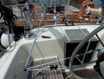
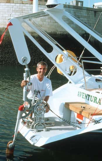
2 WELCOME to the world of silent self-steering! Prepare to be pleasantly surprised by your new windvane steering system: life aboard will never be the same again! Learn to trust your new live-aboard guest. Enjoy the moment you realise it can steer with the kind of stamina and prolonged precision we can only dream of. Hand over to your tireless new mate and make the most of all the time it leaves you for other things. Life aboard will become much more relaxed; time at sea will be generally more restful. And those long trips that were once all but inconceivable are now very much within your grasp. We at WINDPILOT are almost as single-minded as our windvane gears. We have been continuously developing and refining our systems for more than 30 years now - and all that experience comes free with every system sold. You will notice the difference: we have left no stone unturned! KISS (keep it simple, stupid) - that s the motto we live by at WINDPILOT. We realise that manuals are probably well down your list of reading priorities, but there are mistakes to be made and they can be avoided. Good advice is particularly valuable at sea, especially if you have it there on board with you, so take a deep breath and read on You expect good steering from your WINDPILOT and it, in turn, has certain expectations of you: DON T NEGLECT YOUR SAIL TRIM Poor trim amplifies weather helm, which means more pressure on the rudder and less boat speed. Don t sail with the handbrake on! A well trimmed boat heels less and requires less pressure on the rudder. That means it sails faster. Adjust the mast, trim the sails: try it, you have plenty of time! BE AWARE OF THE CONDITIONS Some combinations of wind and sea conditions will be too much for your windvane gear: imagine trying to steer around breaking waves with your eyes closed, for example. MAKE SURE YOUR WINDPILOT IS PROPERLY INSTALLED Install it with care, treat it well and be prepared to give it a little attention now and again. TALK TO US, PREFERABLY RIGHT FROM THE START If you would like confirmation that your system is properly installed and that the steering lines and so on are just right, send us a few photos of your WINDPILOT set up and ready for action. Pictures tell it like it is and make it easier for us to help you. You have our word on it - lazy days at sea await at least as far as steering is concerned Peter Förthmann 2
3 Contents 1.0 INSTALLATION TOOLS INSTALLATION OPTIONS POINTS TO CONSIDER BEFORE INSTALLATION ASSEMBLING THE SYSTEM AFTER DELIVERY POSITIONING THE SYSTEM BAD AIR AND THE WINDVANE PENDULUM RUDDER AND MAIN RUDDER ON LAND OR IN THE WATER? INSTALLATION: QUICK GUIDE THE FIVE CRITERIA INSTALLATION: COMPREHENSIVE GUIDE HEIGHT ABOVE THE WATERLINE INSTALLATION BY MOUNTING BRACKET TYPE MOUNTING BRACKET MB 1 AND MB 2 EXTENSIONS MB 3 AND MB 4 EXTENSIONS MB 5 EXTENSIONS DO I NEED TO REINFORCE THE TRANSOM? WHAT IF THE BRACKET IS ALIGNED INCORRECTLY? INSUFFICIENT SPACE FOR THE MOUNTING BRACKET (MB 0 ONLY) MOUNTING THE SYSTEM ON THE MOUNTING BRACKET IS THE WINDVANE SHAFT VERTICAL? REMOTE CONTROL ALIGNMENT PENDULUM RUDDER LIFT-UP THE STEERING LINES GENERAL THE BASICS WINDPILOT SYSTEM REQUIREMENTS BE AWARE CROSSBAR DEDICATED BREAK POINT FOR STEERING LINES SHOULD I SPLICE THE STEERING LINES? STEERING LINES AND TILLER STEERING POSITIONING THE TILLER FITTING POSITIONING THE RING ON THE PENDULUM ARM STEERING LINE BLOCKS LINE TENSION CENTRING THE TILLER AND THE CHAIN STEERING LINES AND WHEEL STEERING FITTING THE WHEEL ADAPTOR RIGGING THE STEERING LINES CONNECTION POINT LINE TENSION TRANSMISSION RATIO VARIABLE FORCE TRANSMISSION FORCE TRANSMISSION WITH WHEEL STEERING: EXAMPLES TEST STEERING LINES AND THE EMERGENCY TILLER MECHANICAL WHEEL STEERING 17 3
4 HYDRAULIC WHEEL STEERING THE PENDULUM RUDDER MOUNTING THE RUDDER BLADE POSITIONING THE RUDDER BLADE OVERLOAD PROTECTION PENDULUM RUDDER LIFT-UP WINDPILOT AND AUTOPILOT CONFIGURATION SAILING WITH YOUR WINDPILOT SAILING WITH YOUR WINDPILOT: QUICK GUIDE SAILING WITH YOUR WINDPILOT: COMPREHENSIVE GUIDE SYSTEM NOT IN USE PREPARING FOR USE CONNECTING THE STEERING LINES TILLER STEERING WHEEL STEERING ALTERING COURSE/TURNING FINE TRIM - TILLER STEERING FINE TRIM - WHEEL STEERING IS THE VARIABLE FORCE TRANSMISSION SET CORRECTLY? DETERMINING THE IDEAL SETTINGS SETTING THE WINDVANE FOR DIFFERENT WIND STRENGTHS LIGHT WINDS MODERATE WINDS STRONG WINDS THE IDEAL WINDVANE POSITION WINDPILOT AND AUTOPILOT SWITCHING BACK TO MANUAL STEERING EMERGENCY NORMAL USE REMOVING THE SYSTEM IN HARBOUR/FOR WINTER STORAGE CAUTION MAINTENANCE BEARINGS CLEANING BEVEL GEAR LINKAGE PUSH ROD WORM GEAR 260/ CAST AND TUBULAR COMPONENTS LANOLIN ANTIFOULING WINDVANE WINDVANE TELLTALE TROUBLESHOOTING SYSTEM IS TURNING THE WRONG WAY SYSTEM PERFORMANCE IS NOT SATISFACTORY POSITION OF PENDULUM RUDDER BLADE STEERING LINES RIGGED INCORRECTLY THE PENDULUM RUDDER IS NOT MOVING 25 DEGREES TO EACH SIDE SYSTEM IS STICKING AT THE WINDVANE AT THE RUDDER AXLE 27 4
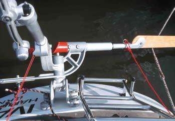
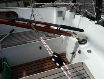
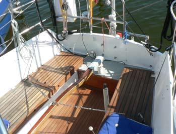
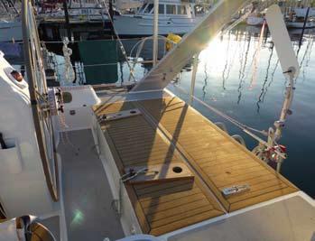
5 5.3.3 AT THE STEERING LINES THE PUSH ROD IS BENT THE WINDVANE SHAFT IS LOOSE THE RUDDER BLADE IS VIBRATING REPAIRS 28 Parts list Accessories 29 Parts list Pacific Mounting 31 MOUNTING OPTIONS MF CATAMARANS 41 STERN LADDER 42 WRONG PERFECT 43 LINE TRANSFER 44 5
 10 mm")


6 PACIFIC 1.0 INSTALLATION 1.1 TOOLS rule pencil 2.5 mm, 5 mm, 6 mm, 8 mm and 10 mm Allen keys (included in delivery package) 10 mm drill bits 10 mm, 17 mm and 19 mm ring/fork wrench/ spanner Sikaflex sealing compound rubber mallet drill 1.2 INSTALLATION OPTIONS MB 0 MB 1 MB 2 MB 3 MB 4 MB 5 CB WC AP standard multifunctional mounting bracket for moderately raked sterns multifunctional mounting bracket with extension for special sterns multifunctional mounting bracket with extension for extreme sterns multifunctional mounting bracket with extension for small sugar scoop sterns multifunctional mounting bracket with extension for extreme sugar scoop sterns multifunctional mounting bracket for sterns with a transom-hung rudder crossbar for steering lines on extreme sterns wheel adaptor for boats with wheel steering autopilot support 6
 such that the bolt engages in the hole in the windvane shaft.")
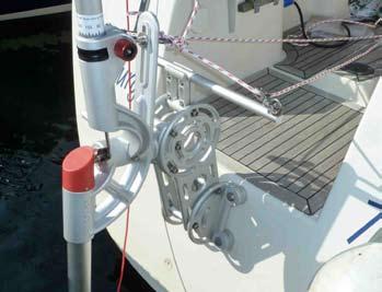
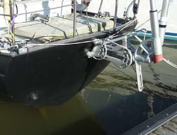
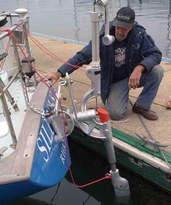
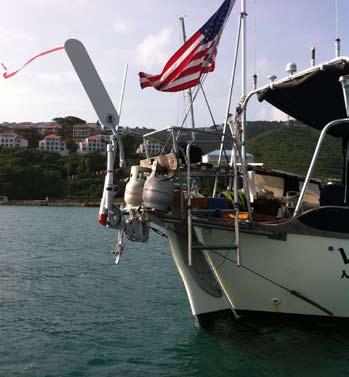
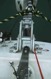
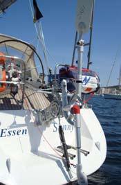
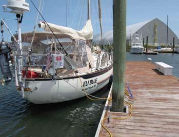
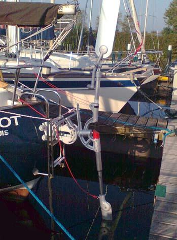
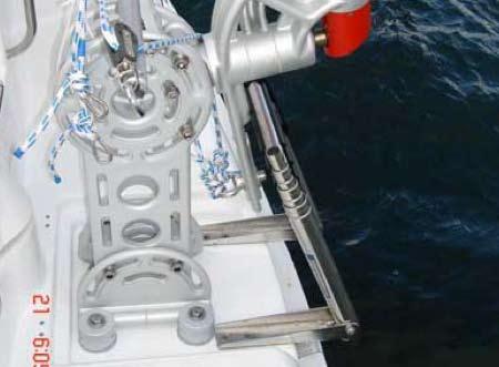
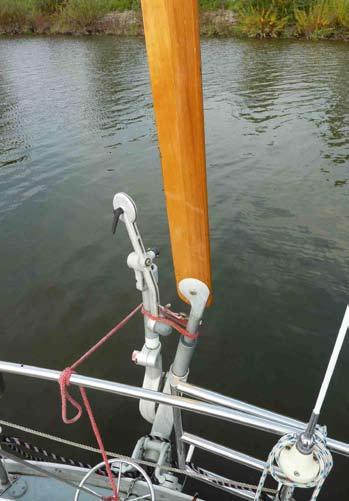
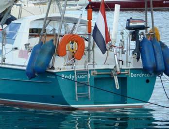
7 1.3 POINTS TO CONSIDER BEFORE INSTALLATION ASSEMBLING THE SYSTEM AFTER DELIVERY The PACIFIC was partially assembled before leaving our premises. Place the base of the windvane assembly 130 on windvane shaft 140 and fasten with the Allen key (5 mm) such that the bolt engages in the hole in the windvane shaft. Guide push rod 150 through ring 152 from below. Set washer 153 and nut 154 on the top of push rod and tighten. Now unscrew nut 154 very slightly (1/8 of a turn). The windvane assembly 130 should now be able to rotate freely about the push rod 150. Mounting bracket 0 is delivered fully assembled. Mounting brackets 1-5 are delivered with one half of the unit assembled. Assemble the other half as the mirror image of the first POSITIONING THE SYSTEM Your WINDPILOT should be installed at the centre of the transom approximately 10 cm/4 in below deck level. Off-centre installation is possible (max. 10 cm/4 in) but not ideal. If your boat has a centrally mounted bathing ladder, it should be relocated to the port side. CAUTION: think twice before moving the ladder to the starboard side. When the pendulum rudder is raised, the pendulum arm 300 swings down very close to the bottom of the transom on the starboard side - check for clearance. TIP: install the PACIFIC first, then sort out the bathing ladder. Tie safety lines to all components before you start. Secure clamps 860 on the mounting bracket with tape. Coat the mounting bolts with lanolin or Duralac. Should I use a spirit level? No, boats are never perfectly level; it is better to trust your eye BAD AIR AND THE WINDVANE The windvane should not be subject to disturbed airflows in its working position. Any unnecessary turbulence will impair the quality of the steering impulses it provides. NO PROBLEM Bad air from a sprayhood: the sprayhood is normally far enough from the stern not to be a problem. 7
 Bad air caused by people in the cockpit PROBLEM Bad air off the mizzen sail Bad air caused by an outboard motor on the pushpit")
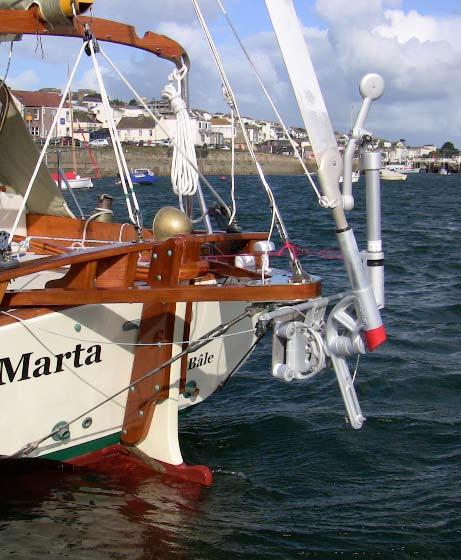
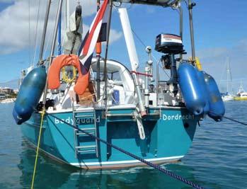
8 Bad air around davits - provided the dinghy is not still hanging from them! Bad air from the superstructure Bad air off the mainsail (sloop/cutter) Bad air caused by people in the cockpit PROBLEM Bad air off the mizzen sail Bad air caused by an outboard motor on the pushpit Bad air caused by fenders/liferaft on the pushpit Bad air caused by a dinghy on the davits PENDULUM RUDDER AND MAIN RUDDER The pendulum rudder is used simply to generate hydrodynamic force; since it does not steer the boat directly, is ok for it to be close behind the trailing edge of the main rudder. The pendulum rudder moves laterally in operation. Turbulence caused by the main rudder does not interfere with the operation of the pendulum rudder ON LAND OR IN THE WATER? You can fit your WINDPILOT with the boat ashore or afloat: it doesn t really matter, as all the holes are above the waterline. But you may be able to find the height above the waterline for installation more easily and accurately with the boat in the water. 1.4 INSTALLATION: QUICK GUIDE THE FIVE CRITERIA 1 Installation height: mounting bolt 435 for the pendulum rudder blade 440 should be cm/4-8 in above the water (static waterline). 2 Overhanging/traditional sterns: does ring 345 on the pendulum arm 330 swing clear of the top of the transom/pushpit when the pendulum rudder is raised? And is the ring clear of the transom in the lift-up position? 3 Forward-raked/sugar-scoop sterns: does pendulum rudder shaft 420 swing clear of the bottom/ aftermost edge of the transom? Nr.140 VERTIKAL! 4 Start by fastening the mounting bracket 800/810 in place with just one bolt. Then align the bracket, mark where the remaining holes should be and predrill them with the 9 mm bit. Now drill out the holes with the 10.5 mm bit and complete installation of the mounting bracket. 5 Align the system: Windvane shaft 140 must be vertical! 8

 and canoe sterns. INSTALLATION PROCEDURE Locate the mounting bracket on the transom at the appropriate installation height.")
. Predrill three holes through the clamps 860 (9 mm bit). Remove the bracket.")
9 1.5 INSTALLATION: COMPREHENSIVE GUIDE Remember the five criteria HEIGHT ABOVE THE WATERLINE The rudder shaft has been manufactured to the correct length for your boat. The dynamic waterline should cover the rudder blade. The rudder will project some distance above the static waterline. Ideal installation height: bolt 435 should be about 5-10 cm/2-4 in above the static waterline INSTALLATION BY MOUNTING BRACKET TYPE MOUNTING BRACKET 0 MB 0 is the standard mounting bracket and is designed for moderate sterns (approx. < -20 degrees to < +10 degrees of rake) and canoe sterns. INSTALLATION PROCEDURE Locate the mounting bracket on the transom at the appropriate installation height. Rotate the four clamps 860 into place against the transom (use the mallet if required). Drill one hole (predrill with the 9 mm bit then complete with the 10.5 mm bit). Pass a bolt through the hole just drilled to hold the bracket in place. Align the bracket (level). Predrill three holes through the clamps 860 (9 mm bit). Remove the bracket. Drill out all the holes with the 10.5 mm bit. Place sealing compound (Sikaflex) around each hole. Set the 60 mm diameter plastic discs on the Sikaflex compound. Position the bracket on the transom and insert all four bolts. Working inside the hull, set the washers on the bolt ends and tighten the nuts/locknuts. SEQUENCE: bolt head/stainless washer/plastic washer/clamp/60 mm plastic disc/sikaflex/transom/ stainless washer/nut/nut MB 1 AND MB 2 EXTENSIONS MB 1 is designed for more extreme sterns (approx. < -40 degrees to < +25 degrees of rake) and transoms incorporating a short bathing platform. 9
 vertical face of the transom. Remember the five criteria.")
10 MB 2 is designed for very extreme sterns (approx. > -40 degrees to > +25 degrees of rake) and transoms incorporating a slightly more substantial bathing platform. INSTALLATION PROCEDURE Brackets 1 and 2 are designed to be installed on the (approximately) vertical face of the transom. Remember the five criteria. Both extension components 820/825 and 830/835 have slots that allow the system to be moved fore and aft, i.e. positioned horizontally. The flat surfaces of these extension components should be vertical with the rounded ends pointing aft. The pendulum arm 300 should swing close to the transom (3-5 cm/1¼-2 in should be enough clearance). This ensures that it will not stick out beyond the aft edge of the transom in the lift-up position and will therefore be safely protected. Remember, the pendulum rudder shaft 420 is angled 10 degrees off vertical. Ideally everything should be as close to the transom as possible for optimal protection in the liftup position. Fit crossbar CB if the steering line angle is greater than 30 degrees (see 1.6 The Steering Lines) MB 3 AND MB 4 EXTENSIONS MB 3 is designed for boats with a large bathing platform where the top of the platform is around 50 cm/20 in above the waterline. MB 4 is designed for boats with a large bathing platform where the top of the bathing platform is < 50 cm/20 in above the waterline. 10

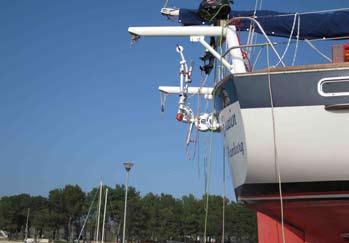
11 INSTALLATION PROCEDURE Brackets 3 and 4 are designed to be installed on the base (horizontal surface) of the sugar scoop. See items 1, 3 and 5 of the five criteria to determine the ideal position. Both extension components 840 and 845 have slots that allow the system to be moved up and down, i.e. positioned vertically. The flat surfaces of the extension components should be vertical with the rounded ends pointing up. The pendulum arm should swing close to the ransom. This ensures that it will not stick out beyond the aft edge of the transom in the lift-up position and will therefore be safely protected. Remember, the pendulum rudder shaft 420 is angled 10 degrees off vertical. NOTE: you can adjust the position of the pendulum rudder with respect to the aft edge of the transom even if the system is already completely installed: loosen bolts 801/811 on the bracket extensions 840/845 and bolts 805 that retain the bracket crown you should now be able to adjust the system fore and aft as required. Don t forget to retighten everything once you ve finished! Fit crossbar CB 880 (see 1.6 The Steering Lines). on the tiller plus the weight of the system itself. The washers supplied provide sufficient load distribution for steel, aluminium, wooden and composite (solid laminate) hulls. Composite hulls built in sandwich laminate: cut the sandwich out from the inside and replace with wood. The wooden sections should be glued into place with synthetic filler (load distribution). CAUTION: If you decide you want to fit steel/ stainless/aluminium transom reinforcement plates anyway, just in case, be sure to pack them in with filler so that the loads are properly distributed! WHAT IF THE BRACKET IS ALIGNED INCORRECTLY? No problem: slacken of the mounting bolts and use the rubber mallet to move the clamps 860 along the bracket sides 810 until the alignment is satisfactory MB 5 EXTENSIONS MB 5 is conceived for boats with a transom-hung rudder, Colin Archer designs etc. INSTALLATION PROCEDURE First fasten the upper pair of arms 850 to the transom with bracket cheeks 820 and clamps 860 so that the main rudder can turn freely (move the clamps closer together or further apart as required). Remember the five criteria. The main rudder must be able to move freely along its length even with the pendulum rudder in the liftup position. Now fit the lower pair of arms 850 with any extension plates required. Ideally all four arms should be level. If you need to align the system, slacken bolts 801/805. Fit crossbar CB 880 if the steering line angle is greater than 30 degrees (see 1.6 The Steering Lines). CAUTION The bolts must be properly seated and tightened - check them regularly! If the bolts work loose, the whole system could be lost. Attach a safety line to your PACIFIC just in case DO I NEED TO REINFORCE THE TRANSOM? No. The forces on the transom are relatively low and should never exceed the steering force exerted 11


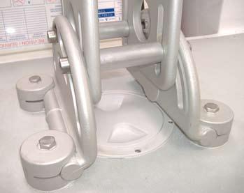
12 1.5.5 INSUFFICIENT SPACE FOR THE MOUNTING BRACKET (MB 0 ONLY) The system may be installed offset horizontally by up to 10 cm/4 in. The bracket may be adjusted vertically on its mountings by sliding clamps 860 along bracket sides 810. There must be at least 8 cm/3 1/5 in of vertical separation between each pair of clamps MOUNTING THE SYSTEM ON THE MOUNTING BRACKET Slide the system into the bracket with the pendulum axle 340 at the front and fasten in place with bolts IS THE WINDVANE SHAFT VERTICAL? Windvane shaft 140 must be vertical. You can adjust it by slackening all four side bolts 801 and both bolts 805 and then aligning the bracket crown 800. Check the alignment of the pendulum rudder shaft 300: it should now be angled aft 10 degrees from vertical REMOTE CONTROL Lead the thin red line supplied through the slot in windvane shaft 250 and around the knurled red knob 270. Knot the two ends of the line together and secure the line in the cockpit with bungee cord. To operate the remote control, take the line in both hands and pull on one side of the loop with one hand while paying the other side without tension with the other hand. Never pull on one side with both hands! ALIGNMENT WINDVANE SHAFT 140 The windvane shaft 140 must be vertical. Side-to-side adjustment: release bolts 801/805 Fore-and-aft adjustment: release bolt 251 Don t forget to retighten the bolts once the windvane is properly aligned! If you still can t make the windvane vertical, see What if the Bracket is Aligned Incorrectly PENDULUM RUDDER LIFT-UP Tie one end of the red lift-up line through ring 345 and secure the other end to the pushpit. Raise the pendulum rudder, take the red line once around windvane shaft 140 and rudder shaft 400 and tie it back to the pushpit. 12

. Anything that impairs the force transmission will have an immediate impact on steering quality.")
 work in exactly the same way.")
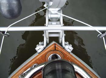
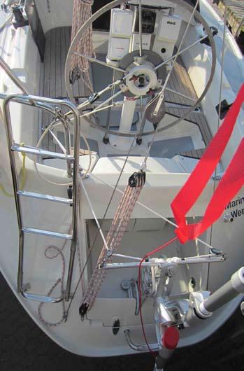
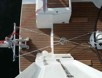
13 1.6 THE STEERING LINES GENERAL The steering performance of your PACIFIC will be strongly influenced by the quality of the force transmission from the pendulum rudder to the main rudder; in other words, you can t have good steering unless the steering lines are working smoothly. Depending on the setting of the variable transmission, the PACIFIC provides maximum steering line travel of between 20 and 25 cm/8 and 10 in (a feature it shares with other popular systems like the Aries and Monitor). Anything that impairs the force transmission will have an immediate impact on steering quality. Slack, stretch or play in the steering lines or stiffness in the main rudder bearings all detract from the performance of your system. Errors and compromises at this point add up to poor steering, plain and simple. All servo-pendulum gears that use the 2:1 bevel gear linkage (Aries, Fleming, Monitor) work in exactly the same way. The differences lie in the operating conditions on different boats! NOTE: what use is cm/8-10 in of travel at the pendulum arm if only a fraction of that reaches the main rudder? THE BASICS Keep the steering lines as short as possible. Use the smallest possible number of blocks. Use non-stretch lines. Make sure the angle formed by the lines between the system and the back of the boat (seen from above) is no greater than 30 degrees. Check the tension of the steering lines. Watch to make sure that line travel is not being wasted between the pendulum arm and the main rudder. Check that the main rudder bearings run smoothly. Check wheel steering systems for play and stiffness WINDPILOT SYSTEM REQUIREMENTS Ring 345 on the pendulum arm must be at deck level. This keeps the steering lines short. There are no unnecessary blocks on the steering lines. There are no blocks fitted to the system itself. The pendulum rudder shaft is long enough to provide plenty of leverage for the pendulum rudder. The bevel gear linkage is working properly to provide automatic yaw damping. The system is sensitive in light airs but powerful in stronger wind conditions BE AWARE Take care when setting up the steering lines 13
 is greater than 30 degrees.")

14 14 between the WINDPILOT and the main rudder. Poor force transmission will seriously impair steering quality CROSSBAR A crossbar should be fitted if the angle formed by the lines between the system and the first set of turning blocks on the back of the boat (seen from above) is greater than 30 degrees. Above 30 degrees the amount of wasted steering line travel becomes a serious problem, especially on larger boats (around 38 ft and upwards) where the full travel is essential for optimal performance. The crossbar is available as an option with mounting brackets 0, 1, 2 and 5 and is standard with mounting brackets 3 and 4. The crossbar 880 is installed adjacent to the top of the mounting bracket. The two aft blocks can then be fitted at the ends of the crossbar to give a much more favourable angle and recover the lost travel DEDICATED BREAK POINT FOR STEERING LINES Two of the turning blocks for the steering lines should be fastened to the boat only with thin cord (e.g. 3 mm burgee halyard). If, for whatever reason, the transmission system should be overloaded, these thin lines will break and save the rest of the setup SHOULD I SPLICE THE STEERING LINES? No, it is better just to use knots as you can then end-for-end the lines easily to spread the wear STEERING LINES AND TILLER STEERING POSITIONING THE TILLER FITTING Tiller fitting 010 should be mounted about 65% of the way along the tiller, measuring from the rear (e.g. if your tiller is 100 cm/40 in long, the fitting should be about 65 cm/26 in from the aft end). Moving the tiller fitting further forward increases leverage but reduces the angle through which your PACIFIC can turn the rudder. Moving the tiller fitting aft increases this angle but reduces leverage. NOTE: it is impossible to have more leverage and more movement at the same time! A servo-pendulum system with automatic yaw damping like the PACIFIC is designed to operate with an average steering line travel between the system and main rudder of cm/8-10 in (once again this is typical of such systems: the Aries and Monitor are just the same) POSITIONING THE RING ON THE PENDULUM ARM Moving the ring up the arm (away from the axle) increases travel but reduces transmission force. Moving the ring down the arm (towards the axle) increases transmission force but reduces travel. See Determining the Ideal Settings.

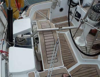
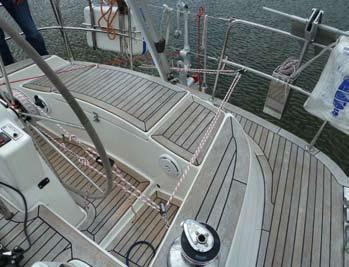
15 STEERING LINE BLOCKS The first pair of blocks should be mounted on or outside the pushpit as far aft as possible. The other pair should be mounted on the cockpit coaming slightly aft of the tiller fitting. Tie the steering lines to the ring 345 on the pendulum arm. Lead them forward to the tiller through the two sets of blocks. Attach the chain section where the steering lines approach the tiller fitting LINE TENSION The lines must be neither too slack nor too tight; either will impair steering. The steering lines should be rigged such that engaging the chain in the tiller fitting sets them to their ideal working tension. IDEAL TENSION: no slack, no strain CENTRING THE TILLER AND THE CHAIN The system and tiller can be centred with respect to each other (e.g. to compensate for weather helm as wind and sea conditions change) by adjusting the chain at the tiller fitting. Assembly sequence: line/shackle/chain/2 snap shackles/line STEERING LINES AND WHEEL STEERING FITTING THE WHEEL ADAPTOR Start by fastening the adaptor to one spoke of the wheel. Make sure the adaptor is centred and then fasten two more clamps to the wheel. Remove the plastic retaining bolt. The adaptor must be able to rotate freely without fouling the spokes. The lines should each be led around the adaptor one and a half times from the point where they attach to it (friction/load distribution). They can then be connected to the steering lines coming from the side/aft (using snap shackles) RIGGING THE STEERING LINES Both lines should initially be led from the ring 345 to their respective corners of the pushpit. If desired, one line may now be led across the pushpit so that both lines are on the same side of the boat. NOTE: keeping both lines on the same side of the cockpit leaves the other side free for access. Take the lines forward until they are level with the wheel. Pass them through a pair of turning blocks and across towards the binnacle. BOTH LINES ON THE PORT SIDE The line that runs from the system to the port side of the boat should be led around the bottom of the wheel adaptor. 15
.")

 so that it can be tensioned perpendicular to the lines using thin cord.")

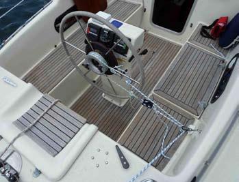
16 BOTH LINES ON THE STARBOARD SIDE The line that runs from the system to the starboard side of the boat should be led around the bottom of the wheel adaptor CONNECTION POINT Each line from the wheel adaptor should be connected to the appropriate steering line from the system using two snap shackles (i.e. four snap shackles in total). This helps when you come to release or reconnect the lines (to engage or disengage the PACIFIC). Ideally the connection should be half way between the binnacle and the pair of turning blocks at the side of the cockpit, but if there is insufficient space, the snap shackles can also be connected between the turning blocks in the cockpit and those on the pushpit. CAUTION: be sure to mark the snap shackles so that you can tell which to connect to which! LINE TENSION Slack can be controlled by including an extra block on the steering lines. This block is mounted (e.g. on the pushpit) so that it can be tensioned perpendicular to the lines using thin cord. The more you tension the cord, the more the block pulls the slack out of the steering lines. Releasing this block provides sufficient slack to uncouple the four snap shackles at the connection point. The block can then be used to re-tension the steering lines once the snap shackles have been reconnected prior to switching over to WINDPILOT steering TRANSMISSION RATIO The wheel adaptor is designed for mechanical wheel steering systems with a range of around two and a half revolutions from stop to stop and a wheel diameter of approximately 60 cm/24 in. This means in practical terms that the maximum line travel of 25 cm/10 in is sufficient to turn the wheel through half a revolution, given perfect transmission VARIABLE FORCE TRANSMISSION The force transmission characteristics can be adjusted using the slot in the pendulum arm 330 (see Determining the Ideal Settings) FORCE TRANSMISSION WITH WHEEL STEERING: EXAMPLES Example 1: Wheel diameter = approx. 60 cm/24 in Revolutions from stop to stop = 2.5 Position of ring 345 = approx. centred in the slot Example 2: Wheel diameter = approx. 100 cm/40 in Revolutions from stop to stop = 1.5 Position of ring 345 = towards the bottom of the slot 16


17 Example 3: Wheel diameter = approx. 55 cm/22 in Revolutions from stop to stop = 3-4 Position of ring 345 = towards the top of the slot TEST It is actually quite straightforward to work out the key parameters for your boat - see Determining the Ideal Settings STEERING LINES AND THE EMERGENCY TILLER MECHANICAL WHEEL STEERING Connecting the steering lines to the emergency tiller of a mechanical wheel steering system will not yield good steering because the tiller has to move the whole of the steering mechanism from the wrong end every time it tries to turn the rudder. It s like trying to turn the steering wheel of your car by sitting in the road and tugging on the front wheels! Good steering can only be had by this route if the transmission components of the wheel steering system are completely disconnected from the quadrant (emergency) HYDRAULIC WHEEL STEERING Connecting the steering lines to the emergency tiller of a hydraulic steering system is pointless, as the tiller cannot possible supply enough force effectively to move the hydraulic cylinder. A bypass valve will not help either. Good steering can only be had by this route if the transmission components of the wheel steering system are completely disconnected from the quadrant (emergency). A word of advice for anybody still tempted to try connecting a servopendulum system up to a hydraulically operated main rudder: don t do it - you ll end up steering by hand! NO 1.7 THE PENDULUM RUDDER MOUNTING THE RUDDER BLADE 440 The blade should be mounted with the rounded edge facing forward and the sharp edge facing aft POSITIONING THE RUDDER BLADE The pendulum rudder blade must be angled down and aft exactly in line with the rudder shaft, otherwise the balance will be off. Adjusting the rudder blade aft reduces the force generated (by reducing the balance proportion). Adjusting the rudder blade forward increases the balance proportion excessively, with the result that the rudder controls the windvane instead of the other way around. Both the adjustments described impair the performance of the system and make steering problems inevitable. 17


18 1.7.3 OVERLOAD PROTECTION Mounting bolt 435 for the rudder blade 440 should be tightened gently so that the rudder blade can still swing up if it strikes something below the water. The rudder blade is retained in the shaft fork by friction only PENDULUM RUDDER LIFT-UP Tie one end of the red lift-up line through ring 431 and secure the other end to the pushpit. Raise the pendulum rudder, take the red line once around the windvane shaft 140 and rudder shaft 420 and tie it back to the pushpit. It is not possible to raise the pendulum rudder out of the water while the boat is moving as the resistance is generally too high. Lift-up under way may be possible at speeds below two knots. The pendulum rudder may be dropped back into the operating position at any time. 1.8 WINDPILOT AND AUTOPILOT CONFIGURATION MB 0 A pin suitable for connecting an Autohelm or Navico push rod autopilot is included as standard on the windvane hanger 110 of every WINDPILOT system. Find a good spot to attach the cockpit autopilot to the pushpit. The autopilot should be at approximately the same height as the pin on the windvane hanger. Rotate the windvane shaft into a position where the autopilot push rod can move through its full travel from stop to stop unimpeded. Mark this position on the windvane shaft. Fit the mount for the autopilot to the pushpit (e.g. on a wooden block on the railing). The autopilot/windvane combination should only be used to steer compass courses. The autopilot/windvane combination will not perform well motoring in calm conditions as turbulence from the propeller interferes with the proper operation of the pendulum rudder. The autopilot should be connected directly to the tiller or wheel in these conditions; since the engine is running, there is no need to save power by using the windvane anyway. See 2.0 Sailing with Your WINDPILOT for operating instructions. CAUTION: always secure the autopilot with a safety line! MB 1-5 If your PACIFIC uses a crossbar for the steering lines and it is not possible to mount the autopilot on the pushpit, fit additional clamp 870/875 with the autopilot support onto the mounting bracket and adjust the length and position as required. 18
. Connect the steering lines to the boat s main steering. Fine trim the steering at the system or the main rudder. 2.")
.")


19 2.0 SAILING WITH YOUR WINDPILOT 2.1 SAILING WITH YOUR WINDPILOT: QUICK GUIDE Bring the boat onto course. Lower the pendulum rudder blade into the water. Fit the windvane. Set the windvane into the wind (it should now be standing upright). Connect the steering lines to the boat s main steering. Fine trim the steering at the system or the main rudder. 2.2 SAILING WITH YOUR WINDPILOT: COMPREHENSIVE GUIDE SYSTEM NOT IN USE Keep the pendulum rudder blade in the lift-up position. Remove the windvane PREPARING FOR USE Bring the boat onto course. Lower the pendulum rudder blade into the water. Fit the windvane and turn it into the wind manually (the windvane should now be standing upright). NOTE: the counterweight should now be pointing into the wind CONNECTING THE STEERING LINES TILLER STEERING Connect the two snap shackles. Engage the chain in the tiller fitting. Remove any slack in the lines. CAUTION: only remove the slack. Do not pull the lines taught, as this increases friction and impairs steering WHEEL STEERING Connect the two pairs of snap shackles (make sure the lines are not crossed!). Remove any slack in the lines. CAUTION: only remove the slack. Do not pull the lines taught, as this increases friction and impairs steering ALTERING COURSE/TURNING Turn the windvane shaft 140 either manually or with the remote control and refer to the degree scale on the windvane shaft FINE TRIM - TILLER STEERING If wind/weather helm change, adjust the rudder position by changing the chain link in the tiller fitting. 19
.")
20 The windvane should work evenly around the upright position most of the time. If it is permanently off to one side, adjust your sail trim or reef down. NOTE: your PACIFIC can exert up to 200 kg/440 lbs of tensile force on the main steering, but sailing with the rudder well over all the time is highly undesirable (i.e. slow). Trim your boat and your sails - it s simpler and you ll get there faster! You can tell if your trim could/should be improved just by looking at the tiller. If the tiller is constantly off-centre, something needs to be done! FINE TRIM - WHEEL STEERING Release the levers on the wheel adaptor. Adjust the main wheel until the boat is properly balanced. Retighten the levers. CAUTION: do not overtighten the adaptor levers. The adaptor works like a disc brake: if the system is overloaded, the drum slides on the disc to absorb the excess force and prevent damage to itself or the other transmission components. TIP: it is not necessary to release the adaptor levers completely to fine trim at the wheel. The whole operation is easier if they are simply loosened enough to allow the adaptor to slide. It is normally sufficient on boats up to 36 ft or so to tighten only one of the levers. The second lever can then be tightened if required in more difficult conditions IS THE VARIABLE FORCE TRANSMISSION SET CORRECTLY? With the boat making good speed, manually turn the windvane all the way to one side and hold it there: If the pendulum rudder moves approx. 25 degrees to one side, the force transmission is set correctly. If the pendulum rudder moves significantly less than 25 degrees, slide ring 345 a little further down the pendulum arm (less travel but more force). If you have tiller steering, you could alternatively move the tiller fitting forward (never move the fitting aft) DETERMINING THE IDEAL SETTINGS The pendulum arm should always be able to make use of its full 25 degrees of travel to each side. This can be adjusted by moving the transmission point (ring 345). TIP: leave the ring in the centre of the slot until you have tested everything properly under sail. If the pendulum arm reaches 25 degrees off-centre too quickly and easily, move ring 345 up the slot (longer lever). Keep testing the settings and moving the ring up until the lateral travel of the pendulum arm begins to be limited to less than 25 degrees. Now gradually move the ring 345 back down the slot, testing the different settings as you go, until the pendulum arm is just able to reach the full 25 degrees of travel. 20


21 CAUTION: larger, heavier boats may need to reach a relatively high boat speed to move the pendulum arm through the full 25 degrees. The force generated by the servo system is always dependent on leverage, rudder area and speed. These factors are the product of physical laws, the consequences of which are inescapable! SETTING THE WINDVANE FOR DIFFERENT WIND STRENGTHS LIGHT WINDS Set the windvane absolutely vertical for maximum sensitivity. The upright setting also provides maximum steering force with the wind from astern. A strip of spinnaker cloth ( windvane telltale ) on the upper trailing edge of the vane further improves sensitivity. CAUTION: you should not need to use a larger windvane in light airs. If you do use a larger vane, it must be exactly the same weight as the standard vane. This setting is particularly suitable for sailing with the wind aft of the beam, when the apparent wind strength is always relatively low MODERATE WINDS Set the windvane angled back 20 degrees away from the wind. This position is the general setting for sailing with the wind forward of the beam (relatively high apparent winds) STRONG WINDS Angle the windvane further back from the wind (more damping). If the windvane begins to vibrate in very strong winds, try angling it back even further. The vane can go as far as about 70 degrees back, which should improve damping and give smoother steering impulses (and hence better steering). This position is the general heavy air setting THE IDEAL WINDVANE POSITION The windvane should always be working evenly around the upright position. If all the movement is occurring on one side, i.e. between the upright position and one of the end stops, adjust the tiller connection or wheel adaptor position until the movement is more evenly distributed. If the windvane is permanently well over to one side, correct the course setting at the windvane shaft either manually or using the remote control. Check the degree scale. NOTE: the reading on the scale at the windvane shaft 140 may differ slightly from the reading on your wind instrument. This is because wind conditions at deck level tend to be different from those at the top of the mast. 21

22 WINDPILOT AND AUTOPILOT PREPARING FOR USE Remove the windvane. Turn the windvane shaft to the marked position. Fit and secure the cockpit autopilot. Connect the power supply. Connect the steering lines to the boat s main steering. Switch the cockpit autopilot from standby to on. CAUTION: check the polarity at the autopilot. If it turns to starboard when you request port, you need to reverse the polarity. Reversing the polarity should be a simple two button function on most of today s cockpit autopilots (check the autopilot manual). TIP: the PACIFIC/autopilot combination only makes sense on a larger boat (6 metric tons or heavier) with wheel steering if the boat has no conventional cockpit wheel autopilot SWITCHING BACK TO MANUAL STEERING EMERGENCY Disconnect the steering lines from the main steering (tiller: disengage chain, wheel: release wheel adaptor adjustment levers). The windvane gear is now completely isolated and will not interfere with the steering in any way. You may alter course as desired NORMAL USE 22

23 Remove the windvane. Disconnect the steering lines from the main steering. Lift up the pendulum rudder using the red line. CAUTION: slow down before attempting to lift up the pendulum rudder. If the boat is moving too fast, there will be too much resistance to raise the pendulum rudder. The pendulum rudder may actually be left in the water without doing any harm, but don t forget to lift it up out of the way before entering harbour/ manoeuvring under engine REMOVING THE SYSTEM IN HARBOUR/ FOR WINTER STORAGE Release bolt 805. Secure the system with a safety line. Remove the system. There is no need to remove the mounting bracket. CAUTION: When fitting/removing your PACIFIC be sure never to handle/lift it by the windvane shaft 140 alone. The shaft is retained on the worm gear 260 by just two M4 bolts 261 and is not designed to bear the weight of the whole unit. The system is best handled/lifted using the casting 250 at the base of the windvane shaft. 3.0 CAUTION The WINDPILOT PACIFIC is a servo-dynamic system. Keep hands well away from the pendulum arm when the system is in operation (trap hazard). Take care when adjusting the windvane shaft manually (e.g. changing course) while the vane is in operation: moving parts can be dangerous. The pendulum rudder can only be raised into the lift-up position at boat speeds of less than 2 knots. The pendulum rudder may be dropped back into the operating position at any time. Always secure the system with a safety line before attempting to fit or remove it. Check the mounting nuts and bolts on the transom regularly. CAUTION: the system may be lost if the mounting bolts work loose. Never use the system if the bolts are known to be loose. When fitting or removing the system handle/lift it only using the pendulum arm and the casting at the bottom of the windvane shaft! 4.0 MAINTENANCE 23
24 The system is largely maintenance free. It is, however, as susceptible to the effects of sun, salt and dirt as anything else onboard and will reward you for a little attention. Please take note of the care guidelines below. Follow them, and your WINDPILOT system should keep going indefinitely. 4.1 BEARINGS The bearings are made from Teflon, POM and Delrin. These materials must not be oiled or greased. Grease or oil in contact with seawater quickly solidifies, causing bearings to stick or seize. 4.2 CLEANING Clean the system with fresh water and rinse thoroughly. TIP: thoroughly soak your PACIFIC in salt water (15 minutes should be long enough) at twilight on a damp evening and then rinse with fresh water. This applies equally to the rest of the boat. Salt crystals and sunlight soon take the gloss off any shiny surface, but a thorough soak and rinse at the end of every long trip will keep your boat looking its best. 4.3 BEVEL GEAR LINKAGE Clean the bevel gear linkage twice a year. Clean any salt or oil from bearing 328. Make sure the gears are in the right position when reassembling the linkage (see 5.0 Troubleshooting). Never grease bearing 328! Axle 334 may be treated with WD-40 or Teflon spray. TIP: try to avoid leaving your system exposed for long periods without use (remove or cover the system). When the pendulum rudder is in the lift-up position, dew and rain wash accumulated dirt and grime off the rudder and rudder shaft down into the bearings, causing them to seize. The bearings can only become blocked with salt/dirt like this in the lift-up position; the same can never happen in the operating position! REMOVING THE SMALL BEVEL GEAR 305 Remove red cap

25 Release screw 163 to remove push rod 150. Remove bolt 251 to release the windvane support 250. Slide the pendulum arm 330 and the windvane support 250 forward off the pendulum axle 340. CAUTION: watch out for bearing rings 341. Release nut 331. Release screw 334. Remove bevel gear and clean. 4.4 PUSH ROD 150 Always check that the top (156) and bottom (160) universal joints turn smoothly on the push rod. If they stick at all, try loosening the connections. Apply WD-40. PUSH ROD POSITION Nuts 154 are adjustable. Ideal position: windvane vertical, pendulum arm 330 vertical, pendulum rudder 440 in line with keel, arm of small bevel gear 305 in the quarter past twelve position 4.5 WORM GEAR 260/270 The worm gear will appreciate a drop of washing up liquid or a squirt of silicone/teflon/wd-40 spray every so often. If the worm gear is sticking, release bolt 273 and nut 271, remove the worm 270 and clean it. 4.6 CAST AND TUBULAR COMPONENTS All the cast and tubular components in the system have been treated with lanolin before assembly and will come apart again readily even after prolonged operation. Wax the tubular components occasionally. 4.7 LANOLIN Lanolin has been applied to all screwed or bolted joints to prevent electrolytic reactions. Lanolin works equally well on all the other screws and bolts on the boat. and also makes a good hand creme! 4.8 ANTIFOULING Never antifoul the pendulum rudder blade. It should 25

26 only be in the water when the system is in use, so there should never be any growth on it anyway. The pendulum rudder blade can be cleaned in the lift-up position. Antifouling may clog the bearing if liquid paint runs up the blade in the lift-up position. TIP: treat the blade with varnish only. 4.9 WINDVANE A spare or replacement windvane must weigh exactly the same as the original windvane. If it does not, adjust the dimensions until it does. CAUTION: even a coat of paint can significantly add to the weight of your windvane. The painted windvane must weigh exactly the same as the original it is to replace. The counterweight is matched to the weight of the original windvane. Using a windvane of a different weight will reduce the sensitivity of the system and impair steering quality, especially in lighter airs. The windvane may be no more than 50 g/1¾ oz lighter than the counterweight. It must never be heavier than the counterweight! 4.10 WINDVANE TELLTALE There comes a point where there is just too little wind to move the windvane. The fluttering of the windvane telltale, a strip of spinnaker cloth attached towards the upper trailing edge of the vane, provides that little extra steering impulse and extends the range of conditions over which the system can sensibly be used. 5.0 TROUBLESHOOTING 5.1 SYSTEM IS TURNING THE WRONG WAY Are the steering lines connected wrongly to the wheel adaptor? See Rigging the Steering lines. 5.2 SYSTEM PERFORMANCE IS NOT SATISFACTORY Is the pendulum rudder positioned correctly? See 1.7 The Pendulum Rudder. NO POSITION OF PENDULUM RUDDER BLADE If the pendulum rudder blade is too far aft, the balance proportion will be too small and the system will only be able to steer at relatively low speeds. No effective steering impulse will be generated at higher speeds. If the pendulum rudder blade is too far forward, the balance proportion will be too large. The pendulum rudder will be moving the windvane instead of the other way around, leaving the system completely unable to steer. Lower the pendulum arm into the water. If it immediately starts swinging around and seems unable to settle on centre, the pendulum rudder is 26
27 too far forward STEERING LINES RIGGED INCORRECTLY Are the transmission angles ok? See 1.6 The Steering Lines. Do you need a crossbar? See 1.6 The Steering Lines. Are the steering lines free of slack, stretch and play? See 1.6 The Steering Lines THE PENDULUM RUDDER IS NOT MOVING 25 DEGREES TO EACH SIDE See Is the Variable Force Transmission Set Correctly. 5.3 SYSTEM IS STICKING AT THE WINDVANE Does the windvane hanger 110 turn easily on axle 113? Check screw connection 113/116 and adjust if required. Are the screw connections on the push rod 150 and the top and bottom universal joints 156/160 properly adjusted? The universal joints must turn freely on the push rod. The upper screw 301 on the pendulum arm 330 must not be too tight otherwise bearing 328 will stick AT THE RUDDER AXLE If there is friction at the rudder axle, the system will have to be disassembled and cleaned. DISASSEMBLY PROCEDURE Remove the system from the transom. Remove red cap 320. Remove screw 254. Push shaft 255 down out of bevel gear 253. Mark the relative positions of the two gears in the bevel gear linkage. Clean bearing 328. ASSEMBLY PROCEDURE Check the position of the two gears. The lever on the small gear 305 should be in the quarter past twelve position. Check that the pendulum arm is vertical. Check that the pendulum rudder blade is in line with the keel. Check that the hole in bevel gear 253 is flush with the hole in shaft AT THE STEERING LINES Do the blocks move freely? Are the transmission paths too long? 27
. The push rod can be straightened easily. 5.")
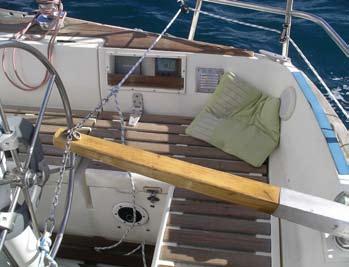
28 Is the wheel too far from the transom (centre cockpit)? Are the main rudder bearings stiff? Is the wheel steering system stiff? 5.4 THE PUSH ROD IS BENT Check the balance proportion of pendulum rudder blade 440 (see 1.7 The Pendulum Rudder). The push rod can be straightened easily. 5.5 THE WINDVANE SHAFT IS LOOSE Tighten bolts 251 and 805. If you have any questions, please do not hesitate to contact us at Headquarter Hamburg Germany tel fax and we ll do everything we can to help! 5.6 THE RUDDER BLADE IS VIBRATING Adjust the position of the pendulum rudder blade 440 in rudder fork 430. The vibrations should die down if you move the rudder blade aft very slightly. CAUTION: do not overtighten bolt 435 (overload protection). 6.0 REPAIRS The system may be disassembled and reassembled using the component drawings. If cast components suffer collision damage and replacements cannot easily be obtained, it may be possible to repair them. Cast aluminium components can be welded back together quite easily if the faces to be joined are first heated thoroughly for a few minutes with an open welding torch flame. The actual welding procedure should only be attempted with proper aluminium welding equipment. 6 mm marine plywood is ideal for making replacement windvanes (see Setting the Windvane for Different Wind Strengths. Some bearing play may develop in pendulum axle bolt 340. This is not a problem and will not impair the steering performance of the system. Pendulum rudder blade The pendulum rudder blade may be replaced with a simple wooden plank (approx. 120 x 900 x 20 mm). Even a completely unprofiled piece of wood will work on a temporary basis. CAUTION: the pendulum rudder needs a balance proportion of around 20%, which means that 20% of the rudder area most be located in front of the rudder shaft. If necessary try turning the blade around. The windvane should always control the pendulum rudder blade and not the other way around. Check this by lowering the pendulum arm 180 into the water. If it immediately swings out to one side and forces the windvane to do the same, there is too much rudder blade in front of the shaft. 28
29 Parts list Accessories Part no. Name Count Dimensions (mm) Materia l Tiller adaptor 010 Tiller fitting 1 20x24x60 Bronze 011 Oval head screw 2 5x15 Stainless steel 015 Steering chain Stainless steel Wheel adaptor 020 Outer ring, left 1 30x200x25 AlMg5 021 Bearing washer 2 10x148x1 Delrin 022 Bearing liner 2 1x148x10 Delrin 023 Collar screw 2 M6x25 slotted Stainless steel 024 Grub screw 1 M8x15 hex head Stainless steel 025 Wheel adaptor line m 030 Inner ring, left 1 30x146x15 AlMg5 031 U-bolt 3 M5 Stainless steel 032 Spacer piece 3 10x20x45 PVC 033 Nut 6 M5 Stainless steel 034 Washer 6 M5 Stainless steel 040 Inner ring, right 1 30x146x15 AlMg5 041 Socket head cap screw 3 M6x15 hex head Stainless steel 050 Outer ring, right 1 30x200x25 AlMg5 051 Clamp lever 2 M8x35 Stainless steel 052 Washer 2 M8 Delrin Crossbar assembly Light 060 Crossbar 65x600 Aluminium 061 Socket head cap screw 2 M8x40 hex head Stainless steel 062 Washer 2 M8 Stainless steel Crossbar assembly Pacific 070 Lower clamp part 1 45x80x130 AlMg5 071 Socket head cap screw 4 M8x25 hex head Stainless steel 072 Washer 4 M8 Stainless steel 073 Nut 4 M8 Stainless steel 075 Upper clamp part 1 45x80x130 AlMg5 076 Spacer piece 1 25x77 Aluminium 080 Crossbar 1 25x600 Aluminium 081 Eye bolt 2 M8x20 Stainless steel 082 Turning block 2 Stainless steel 100 Windvane 1 900x190x6 Plywood 110 Windvane bracket 1 approx. 60x100x460 AlMg5 111 Clamp 1 M8 Stainless steel 112 Washer 1 M8 Stainless steel 113 Windvane axle 1 M10x65 hex head Stainless steel 114 Flange sleeve 2 10x15x15 Delrin 115 Washer 1 M10x30 Stainless steel 116 Nut 1 M10 Stainless steel 120 Counterweight 1 60x90 Lead 29
30 Part no. Name Count Dimensions (mm) Material 130 Windvane head 1 approx. 65x100x150 AlMg5 131 Stud bolt 1 M10x35 hex head Stainless steel 141 Windvane shaft 1 50x450 Aluminium 142 Windvane shaft 1 50x550 Aluminium 147 Bearing collar 1 1x20 Delrin 148 Bearing collar 1 1x20 Delrin 151 Push rod 1 M6x580 Stainless steel 152 Push rod 1 M6x Nut 2 M6 Stainless steel 154 Eye bolt 1 M6 Stainless steel 155 Washer 1 M6 Stainless steel 156 Locknut 1 M6 Stainless steel 157 Socket head cap screw 1 M6x40 hex head Stainless steel 158 Universal joint, upper 1 30x20 Delrin 160 Universal joint, lower 1 30x13 Delrin 161 Locknut 1 M6 Stainless steel 162 Washer 2 M6 Stainless steel 163 Socket head cap screw 1 M6x20 hex head Stainless steel 250 Windvane shaft bracket 1 approx. 70x150x400 AlMg5 251 Socket head cap screw 1 M12x55 hex head Stainless steel 252 Washer 1 M12 Stainless steel 260 Worm gear 1 65x24 Delrin 261 Countersunk screw 2 M4x12 hex head Stainless steel 270 Worm 1 32x88 Delrin 271 Nut 1 M6 Stainless steel 272 Washer 2 M6 Stainless steel 273 Socket head cap screw 1 M6x75 hex head Stainless steel 274 Washer 1 M6 Delrin 301 Stud bolt 2 M10x16 hex head Stainless steel 304 Sleeve 1 10x15x15 Delrin 305 Bevel gear 1 approx. 30x30x70 Bronze 306 Flange sleeve 1 10x15x15 Delrin 320 Top cover 1 75x100 PVC 321 Oval head screw 2 M4x16 slotted Stainless steel 325 Bevel gear 1 70x40 Bronze 326 Countersunk screw 1 M6x35 hex head Stainless steel 327 Bevel gear axle 1 30x160 POM 328 Bearing bush 1 30x64x42 Delrin 330 Pendulum arm 1 approx. 90x240x550 AlMg5 331 Nut 1 M10 Stainless steel 332 Bearing collar 1 1x55 Delrin 333 Bearing collar 1 1x40 Delrin 334 Set screw 1 M10x75 hex head Stainless steel 340 Pendulum arm bolt 1 44x212 Aluminium 341 Bearing washer 1 1x44x75 Delrin 345 Ring nut 1 M12 Stainless steel 346 Washer 2 M12 Stainless steel 347 Socket head cap screw 1 M12x45 hex head Stainless steel 30
31 Part no. Name Count Dimensions (mm) Material 400 Pendulum arm tube 1 60x165 Aluminium 401 Pendulum arm tube 1 60x330 Aluminium 410 Flange sleeve 1 5x50x40 Delrin 420 Rudder shaft 1 40x350 Aluminium 421 Rudder shaft 1 40x450 Aluminium 422 Rudder shaft 1 40x550 Aluminium 425 Slotted spring pin 1 6x40 Stainless steel 430 Rudder fork 1 approx. 45x100x200 AlMg5 431 Socket head cap screw 1 M8x75 hex head Stainless steel 432 Washer 2 M8 Stainless steel 433 Nut 1 M8 Stainless steel 435 Socket head cap screw 1 M10x55 hex head Stainless steel 436 Washer 2 M10 Stainless steel 437 Nut 1 M10 Stainless steel 438 Pin 1 6x45 Delrin 440 Rudder blade head 1 approx. 20x120x145 AlMg5 445 Rudder section 1 20x120x800 AlMg5 450 Rudder section end cap 1 approx. 20x120x20 AlMg5 Parts list Pacific Mounting Part no. Name Count Dimensions (mm) Material 800 Pacific mounting base 1 80x90x160 AlMg5 801 Socket head cap screw 4 M12x45 hex head Stainless steel 802 Washer 4 M12 Stainless steel 805 Socket head cap screw 2 M10x45 hex head Stainless steel 806 Washer 2 M10 Stainless steel 810 Standard mounting bracket 2 45x220x150AlMg5 811 Socket head cap screw 4 M12x55 hex head Stainless steel 812 Washer 4 M12 Stainless steel 820 Mounting bracket 1, left 1 15x220x280 AlMg5 825 Mounting bracket 1, right 1 15x220x280 AlMg5 830 Mounting bracket 2, left 1 15x220x360 AlMg5 835 Mounting bracket 2, right 1 15x220x360 AlMg5 840 Mounting bracket x220x430 AlMg5 845 Mounting bracket x220x500 AlMg5 850 Mounting bracket x90x360 AlMg5 851 Socket head cap screw 4 M8x35 hex head Stainless steel 852 Washer 4 M8 Stainless steel 853 Nut 4 M8 Stainless steel 860 Mounting clamp 4 60x40 AlMg5 31
32 32
33 33
34 34
35 35
36 36
37 37
38 38


39 MOUNTING OPTIONS MF

40 40

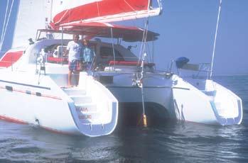


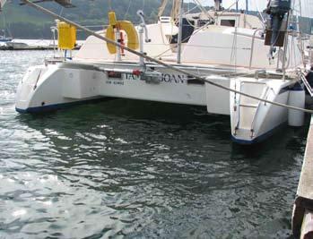

41 CATAMARANS 41


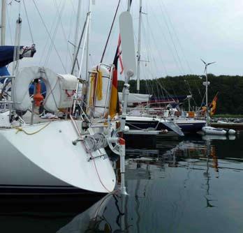
42 STERN LADDER 42


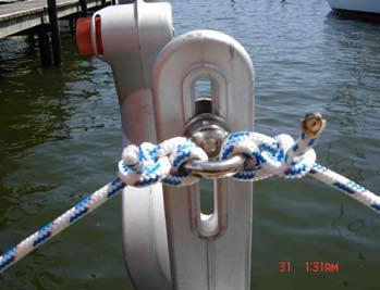
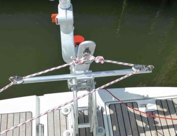
43 WRONG PERFECT NO NO NO 43

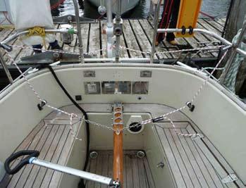
44 LINE TRANSFER 44
45 45


46 46


47 47

48 WINDPILOT...because the wind steers better Bandwirkerstr Hamburg Germany tel: fax:
Bladerider X8 Assembly Help Notes
 2.1 Remove All Parts & Have Some Tools Handy Remove all items from the box and identify each part as per the packing sheet and check that nothing is missing. If there is something missing, please email
An innovative windvane pendulum system for sailing boats with outboard rudders.
 An innovative windvane pendulum system for sailing boats with outboard rudders. Jan Alkema 26 sept. 2005 figure 8. The oar blade retracted figure 7. The oar blade in the water Preface On boats with outboard
INSTRUCTION MANUAL. January 23, 2003, Revision 0
 INSTRUCTION MANUAL Model 810A In-Vitro Test Apparatus for 310B Muscle Lever January 23, 2003, Revision 0 Copyright 2003 Aurora Scientific Inc. Aurora Scientific Inc. 360 Industrial Parkway S., Unit 4 Aurora,
Final Assembly Instructions Bikes with Quill Stems
 Final Assembly Instructions Bikes with Quill Stems Thank you for buying your new bicycle from L.L.Bean. Read these instructions carefully before beginning the final assembly. Prior to shipping, our expert
Final Assembly Instructions Bikes with Threaded Headsets
 Final Assembly Instructions Bikes with Threaded Headsets Thank you for buying your new bicycle from L.L.Bean. Read these instructions carefully before beginning the final assembly. Prior to shipping, our
Table of content Introduction 5 1. Part 1. Assembly Tools needed for Assembly Glossary Hulls Mounting the beams 7
 Table of content Introduction 5 1. Part 1. Assembly 6 1.1. Tools needed for Assembly 6 1.2. Glossary 6 1.3. Hulls 7 1.3.1. Mounting the beams 7 1.3.2. Fixing the mast rotation cleats 8 1.3.3. Placing the
Final Assembly Instructions Bikes with Threaded Headsets
 Final Assembly Instructions Bikes with Threaded Headsets Thank you for buying your new bicycle from L.L.Bean. Read these instructions carefully before beginning the final assembly. Prior to shipping, our
Changing Out the Rear Hub and Sprocket on a 2012 Morgan Three Wheeler Calum Fraser 17/07/2015
 Intro The early Three Wheelers had the rear sprocket in a stepped arrangement relative to the front sprocket with the belt overhanging the sprocket on the outside face. While this is probably less of a
Peinert ZEPHYR. Assembly. The Zephyr is easily rigged; there are only three removable parts - the seat, the foot stretcher, and the rigger arm.
 Peinert ZEPHYR Assembly The Zephyr is easily rigged; there are only three removable parts - the seat, the foot stretcher, and the rigger arm. Removal and installation of the seat. If the seat is in the
M32 CATAMARAN ASSEMBLY MANUAL
 M32 CATAMARAN ASSEMBLY MANUAL 1 M32 CATAMARAN ASSEMBLY MANUAL MANUAL SUMMARY M32 ASSEMBLY Parts and tools Instructions MAST PLATFORM Parts and tools Instructions MAST STEPPING Instructions MAIN HALYARD
600 / 600FC OWNER'S MANUAL
 PROGRESSION 600 / 600FC OWNER'S MANUAL Issue 2 / Version E - Dec. 10, 1997 Copyright 1997 GAMMA Sports - All Rights Reserved PROGRESSION 600 / 600FC OWNER'S MANUAL TABLE OF CONTENTS PAGE 1... WARRANTY
CRYOGENIC TANK SERVICES - CHART RECORDER MANUAL
 CRYOGENIC TANK SERVICES - CHART RECORDER MANUAL Pressure Chart Recorder / Temperature Chart Recorder / Dual Recorder Portable Mechanical Chart Recorder for the accurate measurement and recording of Pressure
Constitution Instructions
 Constitution Instructions This kit will build a 1:48 scale hull for the USS Constitution frigate. The kit contains the following parts. 1/8 deck with laser etched deck lines 1/8 railing Ribs Center keel
ASSEMBLY MANUAL HOBIE CATSY
 ASSEMBLY MANUAL HOBIE CATSY HOBIE CAT EUROPE ZI Toulon Est, BP 50 8078 Toulon cedex 9, France Tel : + (0)9 08 78 78 - Fax : + (0)9 08 99 Email : hobiecat@hobie-cat.net - http://www.hobie-cat.net ASSEMBLY
THUNDER INSTRUCTIONS A LMOST READY TO SAIL MODEL YACHT
 THUNDER INSTRUCTIONS A LMOST READY TO SAIL MODEL YACHT Long: 1000mm High:1890mm Toatl sail area: 0.4 m2 1 MODEL YACHT ASSEMBLY INSTRUCTIONS & SAILING HINTS Thank you for purchasing one of our range of
1 Tuning Platform Reseating Beam Pads Rudder alignment Noisy Foils Rig Tension...
 Contents 1 Tuning... 2 1.1 Platform... 2 1.2 Reseating Beam Pads... 2 1.3 Rudder alignment... 3 1.4 Noisy Foils... 3 1.5 Rig Tension... 4 1.6 Mast rake... 4 1.7 Spreader rake... 5 1.8 Diamond tension...
SERIES 2 RAMP OWNER S MANUAL TOOLS REQUIRED: BEFORE YOU BEGIN... Read and understand these instructions before beginning a ramp setup.
 SERIES 2 RAMP OWNER S MANUAL BEFORE YOU BEGIN... Read and understand these instructions before beginning a ramp setup. Use caution and care for your back when lifting, pushing, pulling, folding or unfolding
Optimist Tuning Guide
 Optimist Tuning Guide Sail Care: To help you re new racing sail stay in top condition as long as possible here is some tips - Try not to crease your sail, some creases can cause MIT tears in your sail
ANGEL INSTRUCTIONS ALMOST READY TO SAIL MODEL YACHT
 ANGEL INSTRUCTIONS ALMOST READY TO SAIL MODEL YACHT Long: 920mm High:1840mm Toatl sail area: 0.4 m2 1 MODEL YACHT ASSEMBLY INSTRUCTIONS & SAILING HINTS Thank you for purchasing one of our range of model
Peinert Dolphin. Assembly
 Peinert Dolphin Assembly The Dolphin is easily rigged; there are only four removable parts - the seat, the foot stretcher, the rigger arm, and the fin. Removal and installation of the seat. If the seat
Rudder Kit Assembly Instructions for Quest 13
 Rudder Kit Assembly Instructions for Quest 13 Revised 4/2/2015 78501 Rudder System The Hobie Quest is designed for the addition of an optional rudder system. Rudder systems in boats like this allow you
A Basic Guide to Europe Dinghy Rigging
 The Basics: A Basic Guide to Europe Dinghy Rigging Use the smallest blocks available for the line size. Most of the blocks on your boat will be micro blocks. Examine all of your rigging and ensure that
VERSA BIKE RACK INSTRUCTIONS
 VERSA BIKE RACK INSTRUCTIONS Models #8, 8 Important This rack is designed for use with a or. receiver hitch. The rack is designed to hold a maximum of two bicycles. Do not use it for anything other than
Installation, Compensation and Maintenance Instructions for. RITCHIE Compasses. Made In U.S.A
 Installation, Compensation and Maintenance Instructions for RITCHIE Compasses Made In U.S.A All Magnetic Compasses are vulnerable to magnetic interference, which will produce errors, called deviation.
Parts List. 7. Handlebars 8. Grips 9. Handlebar Stem 10. Front Brake 11. Front Wheel 12. Crank 13. Chain
 Woodworm Cruise Parts List 1. Free Wheel with Rear Hub 2. Fenders 3. Fender Stay 4. Quick Release 5. Saddle 6. Seat Post 7. Handlebars 8. Grips 9. Handlebar Stem 10. Front Brake 11. Front Wheel 12. Crank
Operating instruction
 Operating instruction MV, XV, HG, HP, RKO, D2G, TV, BV, WB & SLV 1 Introduction 2 2 Stafsjö s knife gate valves 2 3 Technical information 2 3.1 Pressure test 2 3.2 Labelling 2 4 Storage 3 5 Transportation
Installation and Training Manual
 AirForce1 Tower Kit Installation and Training Manual FuturEnergy Limited Ettington Park Business Centre Stratford upon Avon CV37 8BT +44 (0)1789 451070 Table of Contents Safety Notes... 3 Parts Supplied
SEADUCER BOATS GAS MONO COME VISIT US ON THE WEB AT
 SEADUCER BOATS GAS MONO COME VISIT US ON THE WEB AT WWW.SEADUCERBOATS.COM 1 - Pkg. Of 440 push rod ends 1 - Pkg. of solder-on rod ends 2 -water outlet fitting 1-1/4" prop nut 1 -.250" x 24" flex shaft
TUNE YOUR SAILS SPEED. Optimist Tuning Guide. Photo Wavelength
 TUNE YOUR SAILS FOR OUTRIGHT SPEED Photo Wavelength PEAK / HEAD THROAT TACK CLEW THANK YOU for choosing North Sails for your Optimist. Whether you are just starting out in an Optimist you are an experienced
HOME ASSEMBLY INSTRUCTIONS
 HOME ASSEMBLY INSTRUCTIONS This Papillionaire Bicycle now belongs to you. It will take you to work, wait patiently outside your local cafe, and carry your groceries home. This is the start of your long-term
BELT DRIVE INDOOR CYCLING BIKE SF-B1712 USER MANUAL
 BELT DRIVE INDOOR CYCLING BIKE SF-B1712 USER MANUAL IMPORTANT! Please retain owner s manual for maintenance and adjustment instructions. Your satisfaction is very important to us, PLEASE DO NOT RETURN
Assembly Instructions And User Guide
 EZ-1/EZ-CLASSIC QUADRIBENT By Blackbird Designs Inc. Mark 5.2 June 2011 Assembly Instructions And User Guide 1 The Quadribent is 2-seat, side-by-side, human powered vehicle that enables almost anyone to
TECHNICAL DATA ZTR Model 312
 DIXON INDUSTRIES. INC. A BLOUNT COMPANY AIRPORT INDUSTRIAL PARK PO BOX 1569 COFFEYVILLE KS 67337 0945 316 251 2000 FAX 316 251 4117 TECHNICAL DATA ZTR Model 312 IMPORTANT - READ OPERATOR'S MANUAL BEFORE
A. TO PREPARE THE MACHINE FOR USE.
 INSTRUCTION MANUAL FOR THE ML120 STRINGING MACHINE. CONTENTS: A. TO PREPARE THE MACHINE FOR USE. 1. The assembly of frame with console and tooltray. 2. Fixing the lever of the tension unit. 3. Putting
Quattrocycle BV. Quattrocycle. User Manual. Last update February Quattrocycle BV Bremkant EJ Middelbeers. User Manual Quattrocycle 1
 Quattrocycle User Manual Last update February 2010 Quattrocycle BV Bremkant 6 5091 EJ Middelbeers User Manual Quattrocycle 1 Table of Contents Page Chapter 1: Introduction 3 Chapter 2: Instructions for
Index 1. Trampoline 2. Main Foils 3. Spinnaker Pole 4. Mast Setup 5. Mast Rigging 6. Rig Tension 7. Trapeze Lines 8. Rudders 9. Boom 10. Main Sheet an
 By User Manual Index 1. Trampoline 2. Main Foils 3. Spinnaker Pole 4. Mast Setup 5. Mast Rigging 6. Rig Tension 7. Trapeze Lines 8. Rudders 9. Boom 10. Main Sheet and Traveler 11. Main Sail 12. Downhaul
Pico rigging manual 2007.doc Page 1 of 28
 Pico rigging manual 2007.doc Page 1 of 28 Pico Rigging Instructions The Pico rigging instructions are a guide to rigging your boat. Due to production supplies certain parts may be slightly modified from
E Manual Self tacking system 30
 597-205-E 2015-12-09 Manual Self tacking system 30 1 Self tacking system 30, 443-200-10 A self-tacking jib makes life on board a lot easier, in particular for shorthanded crews. The jib sheet is led to
Cleaning rod: spring steel, stainless steel or carbon fibre cleaning rod - only use a one-piece rod. Avoid using snakes.
 Telemark Biathlon Where performance and precision come together http://telemarkbiathlon.com Rifle Cleaning Date : July 19, 2013 Anschutz Rifle Manual - Click Here Izhmash 7-3 Rifle Manual - still looking
Instruction Manual. Features. Specification: Length: 730mm Width: 500mm Height: 1000mm Sail Area: 0.15m 2. Weight: 692g (w/o battery & receiver)
") AN UNBELIEVABLE SPEED MACHINE Instruction Manual Features Specification: Length: 730mm Width: 500mm Height: 1000mm Sail Area: 0.15m 2 Weight: 692g (w/o battery & receiver) Thank you for purchasing your
AN UNBELIEVABLE SPEED MACHINE Instruction Manual Features Specification: Length: 730mm Width: 500mm Height: 1000mm Sail Area: 0.15m 2 Weight: 692g (w/o battery & receiver) Thank you for purchasing your
DM-RD (English) Dealer s Manual. ROAD Rear Derailleur RD-9000 RD-6800 RD-5800 RD-4700
 Dealer s Manual. ROAD Rear Derailleur RD-9000 RD-6800 RD-5800 RD-4700") (English) DM-RD0003-09 ROAD Rear Derailleur Dealer s Manual RD-9000 RD-6800 RD-5800 RD-4700 CONTENTS IMPORTANT NOTICE...3 TO ENSURE SAFETY...4 LIST OF TOOLS TO BE USED...6 INSTALLATION...8 Chain length...
(English) DM-RD0003-09 ROAD Rear Derailleur Dealer s Manual RD-9000 RD-6800 RD-5800 RD-4700 CONTENTS IMPORTANT NOTICE...3 TO ENSURE SAFETY...4 LIST OF TOOLS TO BE USED...6 INSTALLATION...8 Chain length...
Trike-Bike Assembly Manual
 Be sure to check our website for more instruction details, videos and photographs as well as a complete listing of each Nut and Bolt for the Trike Bike. www.trike-bike.com.au Go to the page marked ASSEMBLY
Keel-stepped and deck-stepped masts,
 Keel-stepped and deck-stepped masts, C-sections and F-sections The T-base and deck ring systems are made to fit both Seldén s conventional mast sections and their matching furling sections. They are also
2,500/4,000 LB Easy Riser Vertical Cable Feighner Lift
 2,500/4,000 LB Easy Riser Vertical Cable Feighner Lift CAUTION - PUT SAFETY FIRST 1. Before attempting to install or operate this lift, study and fully understand the proper operating procedures and safety
QUALITY ALUMINUM BOAT LIFTS, INC. INSTRUCTIONS. Dominator Lake Lift
 INSTRUCTIONS Dominator Lake Lift PHONE:251-986-3882 * FAX:251-986-3136 QABLDOMINATORINST.2014 P a g e 1 Quality Aluminum Boat Lifts, INC. Installation Instructions: Dominator Lake Lift Thank you for your
SEADUCER BOATS GAS SPORT HYDRO
 SEADUCER BOATS GAS SPORT HYDRO COME VISIT US ON THE WEB AT WWW.SEADUCERBOATS.COM 2 - Pkg. Of 440 push rod ends 2 - Pkg. of solder-on rod ends 2 -water outlet fitting 1-1/4" prop nut 1 -.250" x 30" flex
Lectric Cycles Mid-Drive Electric Motor Installation
 Lectric Cycles Mid-Drive Electric Motor Installation This write-up describes the installation of a Lectric Cycles electric motor. The model is the e-rad Mid-Drive 750 Watt conversion kit, installed on
BC Shackle. Made in the China. Alloy Steel Anchor Shackle. Instructions for handling and use - Please read in full before using this device
 BC Shackle Made in the China Alloy Steel Anchor Shackle Instructions for handling and use - Please read in full before using this device Index 1.) Introduction 2.) Warnings / General Use Guidelines 3.)
RUDDER KIT INSTRUCTIONS
 C I N S T R U C T I O N S RUDDER KIT INSTRUCTIONS PAMLICOS-0,0,T, T, 60T, Excel Rotomolded Pamlico 0, 0, T, T, 60T, Excel The addition of a rudder to a kayak results in additional control and efficiency,
North Sails Seattle Thunderbird Tuning Guide
 Page 1 of 6 North Sails Seattle Thunderbird Tuning Guide Introduction The following tuning guide is meant as a good starting point in setting up your boat. Since not all Thunderbirds are exactly alike
8-GUN CORVETTE ASSEMBLY INSTRUCTIONS
 8-GUN CORVETTE ASSEMBLY INSTRUCTIONS THE HULL STEP 1 Fasten the Deck to the Hull. Find the hull. This is a large, pink, ship-shaped piece of insulating foam board. This will form the base of your model
1.0 - OPENING AND CLOSING THE DOOR
 The purpose of this manual is to provide the user with instructions on how to safely open and close, how to conduct routine maintenance, and how to install the PEI TWINLOCK Closure on a pressure vessel.
The Definite Guide to Optimist Trim
 The Definite Guide to Optimist Trim by Martin Gahmberg & the WB-Sails team The purpose of this tuning guide is to help you trim your WB sail optimally by learning the effects of the controls: How to change
 Table of content Introduction 5 1. Part 1. Assembly 6 1.1. Tools needed for Assembly 6 1.2. Glossary 6 1.3. Hulls 7 1.3.1. Mounting the beams 7 1.3.2. Fixing the mast rotation cleats 8 1.3.3. Mounting
3/8" Dr. Air Butterfly Impact Wrench
 8192106 3/8" Dr. Air Butterfly Impact Wrench Owner s Manual Read and understand all instructions before use. Retain this manual for future reference. Specifications Construction: Polished aluminum and
400/488 Rotating Davit Installation Instructions
 400/488 Rotating Davit Installation Instructions These instructions were written with the owner in mind. If you are the installer make sure these instructions are passed along to the owner of the boat.
CLASS CYCLE P8000 OWNER'S MANUAL JOHNSON HEALTH TECH. CO., LTD.
 CLASS CYCLE P8000 JOHNSON HEALTH TECH. CO., LTD. No.26, Ching Chuan Rd., Taya Hsiang, Taichung Hsien 428, Taiwan, R.O.C. TEL: +886-4-2566700 FAX: +886-4-2560087 E-mail: sales@johnsonfitness.com http://www.johnsonfitness.com
EZee Glider Manual. Tools needed for Assembly: Wrench (included) Philips Screwdriver (not included) Assembly Instructions
 Philips Screwdriver (not included) Assembly Instructions") EZee Glider Manual Congratulations on your purchase of the EZee Glider! Your glider is designed for years of nearly carefree use by your child. These instructions include how to set up your glider and
EZee Glider Manual Congratulations on your purchase of the EZee Glider! Your glider is designed for years of nearly carefree use by your child. These instructions include how to set up your glider and
Revised 20-20B web page 5 June Advanced
 1 sur 13 30/01/2013 21:23 Revised 20-20B web page 5 June 2005 Advanced URL http://www.mindspring.com/~waltmur/self-steering/ Please note that this site is being reactivated after about a year and there
602 STRINGING MACHINE OWNER'S MANUAL
 PROGRESSION 602 STRINGING MACHINE OWNER'S MANUAL AL Issue 1- April 2000 Copyright 2000 GAMMA Sports - All Rights Reserved PROGRESSION 602 STRINGING MACHINE TABLE OF CONTENTS PAGE 1... WARRANTY PAGE 2...
MASTER TRUING STAND TS-3. Optional Dial indicator set with brackets Dial indicator bracket set only
 MASTER TRUING STAND TS-3 3 2 1 3 8 9 4 10 7 6 5 12 13 Optional 1555-1 Dial indicator set with brackets 1556-1 Dial indicator bracket set only 49 11 16 14 15 48 32 31 37 38 20 19 17 18 34 39 21 36 22 33
TECHNICAL DATA BROCHURE Model 304
 DIXON INDUSTRIES, INC. A BLOUNT COMPANY AIRPORT INDUSTRIAL PARK PO BOX 1569 COFFEYVILLE KS 673370945 316 251 2000 FAX 316 251 4117 TECHNICAL DATA BROCHURE Model 304 IMPORTANT - READ OPERATOR'S MANUAL BEFORE
BUTTERFLY VALVES Series 800
 BUTTERFLY VALVES Series 800 WARNING Before proceeding read ALL instructions and become familiar with the equipment and associated drawings. Follow ALL applicable safety regulations and codes for pressurized
PT 11 trouble-shooting and maintenance.
 PT 11 trouble-shooting and maintenance. Does your rudder not stay down?...your back seat slip off?...your knobs tight and your leather pads loose? Maybe we can help. We have used our PT 11 s hard enough
Southern Eagles Soaring
 Southern Eagles Soaring N56LS Standard Cirrus Disassembly / Assembly Procedure. Version 2, 2017 You landed out so what now? First, hopefully you made arrangements with someone who has a hitch on their
Santa Fe Cycles Assembly Guide Introduction
 Santa Fe Cycles Assembly Guide Introduction Congratulations on your purchase of your new Santa Fe bicycle. You have purchased a bicycle that has many features and qualities. Please take a few minutes and
Mini Glider Manual. Your Glider comes partially assembled. The front wheel and the handlebars require assembly.
 Mini Glider Manual Congratulations on your purchase of the Mini Glider! Your glider is designed for years of nearly carefree use by your child. These instructions include how to set up your glider and
icreasepro Creaser Operators Manual
 6-2013 Version 3.0 icreasepro Creaser Operators Manual WWW.MBMCORP.COM 800-223-2508 TABLE OF CONTENTS SPECIFICATIONS.1a SAFETY PROCEDURES/CARE & MAINTENANCE..1b COMPONENT IDENTIFICATION 2 TOUCH SCREEN
Shoreline Cantilever Lift 2500lb Capacity Models: (108" inside width) - Part # (120" inside width) - Part #
 - Part # (120 inside width) - Part #") Shoreline Cantilever Lift 2500lb Capacity Models: 25108 (108" inside width) - Part # 1017402 25120 (120" inside width) - Part # 1017403 1. 2. 3. 4. 5. CAUTION - PUT SAFETY FIRST Before attempting to install
Shoreline Cantilever Lift 2500lb Capacity Models: 25108 (108" inside width) - Part # 1017402 25120 (120" inside width) - Part # 1017403 1. 2. 3. 4. 5. CAUTION - PUT SAFETY FIRST Before attempting to install
In each step, the needed parts are shown the number right below. Locate all parts for the step.
 Tools Required for Assembly Phillips Screwdriver, Med Needle Nose Pliers Sandpaper (#400 grit) Hobby Knife Scissors CA Instant Glue Rubbing Alcohol Drill Bit 1/16", 1.6mm 5/64, 2mm 1/8, 3mm 5/32, 4mm Before
TABLE OF CONTENTS FRAME FEATURES INTRODUCTION
 S3 DISC MANUAL TABLE OF CONTENTS Introduction...1 Frame Features...2 Fork Preparation...3 Small Parts...5 Frame Preparation...6 Brake Housing Installation...7 Mechanical Cable Routing...9 Electric Cable
COASTAL IN-BOOM FURLING SYSTEM. Installation Manual
 COASTAL IN-BOOM FURLING SYSTEM Installation Manual 1 TABLE OF CONTENTS Page Number 3. Disclaimer 4. Components packing list & required tools 5. Gooseneck bracket location 6. Installation sail track 7.
DM-MBRD (English) Dealer's Manual. ROAD MTB Trekking. City Touring/ Comfort Bike. Rear Derailleur SLX RD-M7000 DEORE RD-M6000
 Dealer's Manual. ROAD MTB Trekking. City Touring/ Comfort Bike. Rear Derailleur SLX RD-M7000 DEORE RD-M6000") (English) DM-MBRD001-04 Dealer's Manual ROAD MTB Trekking City Touring/ Comfort Bike URBAN SPORT E-BIKE Rear Derailleur SLX RD-M7000 DEORE RD-M6000 CONTENTS IMPORTANT NOTICE... 3 TO ENSURE SAFETY... 4
(English) DM-MBRD001-04 Dealer's Manual ROAD MTB Trekking City Touring/ Comfort Bike URBAN SPORT E-BIKE Rear Derailleur SLX RD-M7000 DEORE RD-M6000 CONTENTS IMPORTANT NOTICE... 3 TO ENSURE SAFETY... 4
Parts of the Ship. Terms you should already know
 Parts of the Ship Toronto Brigantine Terms you should already know After-peak Fore-peak Bow Stern Fairlead Scupper Freeing port Hull Deck Lifeline Hatch Skylight Cleat Pin-rail Fife-rail Spider-band Block
3. Fit. 1 Owner s manual
 3. Fit NOTE: Correct fit is an essential element of bicycling safety, performance and comfort. Making the adjustments to your bicycle which result in correct fit for your body and riding conditions requires
RB70 Automatic Diluent Valve Maintenance Manual. Version 1.1 November 2006 Written by Tino de Rijk. Page 1 of 23
 RB70 Automatic Diluent Valve Maintenance Manual Version 1.1 November 2006 Written by Tino de Rijk Page 1 of 23 Table of Contents 1. Introduction... 3 2. ADV diagram and parts list (Pre June 2006)... 4
BoatWasher Swede, , MS Float
 BoatWasher Swede, 400-600, MS Float Cleans the hull from algea, barnacles and other fouling. Cleans both motor- and sailing yachts. Three sizes of washers fits most boat types, up to approximate 25-meter
Thumb Shifter Plus Thumb Shifter
 (English) DM-SL0004-01 Dealer's Manual Thumb Shifter Plus Thumb Shifter Thumb Shifter Plus SL-FT55 SL-TX50 SL-TX30 Thumb Shifter SL-TZ20 IMPORTANT NOTICE This dealer's manual is intended primarily for
7130 Lancer Rear Drive Magnetic Commercial Indoor Cycling Bike
 7130 Lancer Rear Drive Magnetic Commercial Indoor Cycling Bike Owner s Manual Made in Taiwan INDEX IMPORTANT SAFETY INFORMATION... 1 EXPLODED DRAWING... 2 PARTS LIST... 3 ASSEMBLY INSTRUCTION... 4-9 USER
Deluxe Gourd Racks I D E G A. Parts List. Shown above are parts for the two-level, Deluxe Gourd Rack (DGR 12V)with 12 arms for vertically hung gourds.
with 12 arms for vertically hung gourds.") Deluxe Gourd Racks H F K I D E J C G A Shown above are parts for the two-level, Deluxe Gourd Rack (DGR V)with arms for vertically hung gourds. Parts List Code Quantity A B C D E F G H I J 6, or 4 6, or
Deluxe Gourd Racks H F K I D E J C G A Shown above are parts for the two-level, Deluxe Gourd Rack (DGR V)with arms for vertically hung gourds. Parts List Code Quantity A B C D E F G H I J 6, or 4 6, or
OWNERS MANUAL. Model Shown with optional Primary Mooring Cleats. Portable Mooring System SAFETY OPERATION MAINTENANCE PARTS
 OWNERS MANUAL Model 2400 Shown with optional Primary Mooring Cleats. Portable Mooring System SAFETY OPERATION MAINTENANCE PARTS CAUTION: Before using your new Pier Tender, read rules for Safety, Operation,
MAGNETIC INDOOR CYCLING BIKE
 MAGNETIC INDOOR CYCLING BIKE SF-B1805 USER MANUAL IMPORTANT! Please retain owner s manual for maintenance and adjustment instructions. Your satisfaction is very important to us, PLEASE DO NOT RETURN UNTIL
2010 International Snow Science Workshop
 HOW TO TURN A KIDS BIKE INTO A BOMB TRAM FOR AVALANCHE CONTROL WORK David Immeker* Heavenly Mountain Resort Professional Ski Patrol, South Lake Tahoe, California ABSTRACT: Bomb trams have been used for
DX2/DXX Operating Instructions
 CHECK LINE BY ELECTROMATIC DX2/DXX Operating Instructions CHECK LINE INSTRUMENTS ELECTROMATIC E Q U I P M E N T C O., I N C. 600 Oakland Ave., Cedarhurst, NY 11516 U.S.A. TEL: 516-295-4300 FAX: 516-295-4399
U.S. Patent No. 7,922,246. Patents Pending
 U.S. Patent No. 7,922,246 Patents Pending 2 Table of Contents Page General Information... 3 Warnings and Cautions... 4 Tools... 6 SmartDock Parts... 6 Initial Set-Up and Adjustment... 7 Select Valve Retaining
Important! Read this manual before using the reel. Manual english
 mportant! Read this manual before using the reel. Manual english F3W, L5W and H5D series Spool Change System This fly fishing reels are equipped with a spool change system wherein the spool is the only
beaufort OWNER S MANUAL ORION Selfsteering Systems ASMER 18 rue de la Scierie F La Rochelle Phone: +33(0)
") beaufort Selfsteering Systems OWNER S MANUAL ORION ASMER 18 rue de la Scierie F - 17 000 La Rochelle Phone: +33(0)5 46 45 22 20 http://www.asmer.fr e-mail: contact@asmer.fr TABLE OF CONTENTS 1. SPECIFICATIONS...
beaufort Selfsteering Systems OWNER S MANUAL ORION ASMER 18 rue de la Scierie F - 17 000 La Rochelle Phone: +33(0)5 46 45 22 20 http://www.asmer.fr e-mail: contact@asmer.fr TABLE OF CONTENTS 1. SPECIFICATIONS...
Schaefer recognized this issue and they offer to replace the drum bearing assembly for $
 Schaefer 2100 roller furler drum replacement on Catalina 320 Danny Jensen, A BOA VIDA hull #972, Thanks to contributions Chris Burti, Jeff Hare and C320 group for comments Photos were taken and edited
Trogear Bowsprit Through Hull Installation Manual
 Trogear Marine Products, LLC www.trogear.com info@trogear.com 866-616-2978 Trogear Bowsprit Through Hull Installation Manual Congratulations on your purchase of the Trogear Bowsprit which can be installed
Shiftable Unicycle Hub, Type KH
 Shiftable Unicycle Hub, Type KH 10/06/30 schlumpf innovations gmbh Dorfstr. 10 CH - 7324 Vilters/Switzerland Tel: +41 (0)81 723 80 09 Fax: +41 (0)81 723 83 64 email: info@schlumpf.ch www.schlumpf.ch Geschäftsführer/CEO:
Flow Control of the Kite
 SAILING WORLD posted June 16, 2015 Flow Control of the Kite Symmetric spinnakers are often the most dynamic and challenging sail to trim perfectly. By understanding how they behave at different wind angles,
Operation Manual Guillotine Cutter RC-5
 Operation Manual Guillotine Cutter RC-5 Technical Specifications General Safety/Operating Instructions Using the Guillotine Cutter/Crimper Blade Change Instructions Maintenance Instructions This is a detailed
Assembly instructions nortik scubi 2 Recreational kayak
 Assembly instructions nortik scubi 2 Recreational kayak QR-Code assembly video: Assembly instructions nortik scubi 2 Dear Customer, You have purchased a nortik scubi 2, an innovative hybrid kayak for recreational
2. Note that the ropes from the rigging board are secured in the cam cleats of the jib fairleads.
 VII 1. Place the hull, bow into wind, on its trailer, a soft surface, or a rigging board. We strongly recommend making a rigging board; it is simple and inexpensive and greatly simplifies rigging and working
OPPI Rigging Guide 3/2008
 OPPI Rigging Guide 3/2008 McLaughlin Boat Works optistuff.com Thanks for purchasing OPPI, the most durable and F-U-N sailboat available. Rigging your OPPI is easy and the following pictures make it a breeze
User Instructions 1790 Rail Anchor
 User Instructions 1790 Rail Anchor This document is intended to meet the Manufacturer s Instruction requirements as stated by ANSI Z359.1, and should be used as part of an employee training program as
OPERATING INSTRUCTIONS. Parts List N. Note: Owner and operator MUST read and understand this operating instructions before use this lift table.
 OPERATING INSTRUCTIONS Parts List 770N te: Owner and operator MUST read and understand this operating instructions before use this lift table. Thank you for using this lift table. Your lift table is made
2019 MADONE ASSEMBLY MANUAL
 2019 MADONE ASSEMBLY MANUAL 2019 MADONE Rim brakes and Di2 drivetrain Rim brakes and mechanical drivetrain Disc brakes and Di2 drivetrain Disc brakes and mechanical drivetrain TABLE OF CONTENTS Common
Notes for preparing MRC boats for transport to/from Regattas
 Notes for preparing MRC boats for transport to/from Regattas 1. Aim of the training: To safely move boats and other MRC equipment to and from regattas without loss of equipment, nuts, washers etc. and
LIQUIP DRYBREAK COUPLER. API800 Series MAINTENANCE INSTRUCTIONS
 LIQUIP DRYBREAK COUPLER API800 Series MAINTENANCE INSTRUCTIONS API LOADING COUPLER TO API RP1004 June 2015 Issue: F M:\Product-Info\API8xx\6-Service-Maintenance\API800 MAINTENANCE INSTRUCTIONS 40183.doc