Operating Instructions
|
|
|
- Debra Dorsey
- 5 years ago
- Views:
Transcription

1 Operating Instructions
2 Index Page Important Hints 3 1. Instrument Design 5 2. Switch on Instrument 6 3. Choose a storage location (option) 7 4. Gas Analysis 4.1. Measurement Preparations Gas Analysis Draft Measurement Soot...Oil trace Record and print Measurement Result After Measurement Mean value (option) Measurement Routines (option) 6.1. Atmospheric Boilers Fan Burners Gas Fan Burners Oil Fan Burners Diagnosis gas Pressure Tests (option) Adjustments Control Data processing (option) Maintenance Tips Technical Data FAQ 40 Seite 2
3 Important Hints The meets the requirements of the DIN EN Part 3 (Part 2 as option). The may not be used for continuous emission control! Following minimum times must be kept to get correct measurement results: -1 Minute for fresh air calibration -2 Minutes to get stable measurement results Following substances affect the function of the instrument: -solvent containing gases as in: - cleaning agents - fat remove agents - wax polish - adhesives -Formaldehyde Settings on fireplaces should just be made by professionals who are experienced with the function and adjustments of fireplaces! 1. Charge the accumulator regularly (Charge not used instrument min. once a month)! 2. Never store the instrument with unloaded battery! Seite 3


4 Fresh air opening Do not lock fresh air opening for fresh air pump! Seite 4
 Cursor monitoring (up/down/scroll) Instrument")


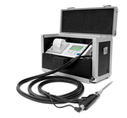
5 1. Instrument Design Store key Print key Enter key (choise confirmation) Cursor monitoring (up/down/scroll) Instrument ON/OFF Printer ESC key (quit/ escape menu) CAL key Standby key Gas temperature connection Sucking temperature connection Charging socket Gas connection Pressure hose connection ecom-lsg connection RS232 interface Draft connection Condensate monitoring connection Seite 5
6 2. Switch on Instrument After switch on the instrument (press <I/0>) the main menu appears on the display. There will be displayed sub-menus with following functions (not visible sub-menus could be displayed by scrolling with arrow keys): Comb.measure. Mean value Atmosph. boiler Diagnosis gas Pressure tests Data processing Adjustment Control Comb. measure. : operate combustion measurement (Mean value : operate mean value measurement)* (Atmospheric boiler : operate routine for atmospheric boilers)* (Fan burner : operate routine for fan burners)* (Diagnostic gas : operate routine for gas fireplaces)* (Pressure tests : pressure tests according to TRGI)* (Data processing : assign measurements / Data transfer)* Adjustments : change adjustments of instrument Control : check operating status of instrument (* = Option) To perform measurements, select with the cursor keys the sub-menu "Gas analysis" and confirm with <Enter>. The instruments starts then a 1- minute calibration phase and the fuel types selection list is displayed. The following fuel types are available: Fuel types acc. to 1 st BImSchV Fuel oil (B) Natural gas (B) City gas (B) Coke oven gas (B) Liquid gas (B) Use the cursor keys to select the desired fuel type and confirm with <Enter>. The instrument will then enquire if you wish to use the data bank (only with option Data processing ).If you want to assign the sampled data to a specific plant, so choose YES with the cursor keys and confirm with <Enter>. ( NO = measurement will be performed without assignment). Seite 6 Type of fuel Fuel oil (B) CO2max : 15.4 A1-fact. : 0.50 Select with! Data processing NO Are you sure? Continue with :
7 3. Input or select a data record (Option) The has 300 storage locations (option). In order to call up a data record with data are already stored in the instrument or to create a new file, choose a data record with the Cursor keys and confirm with <Enter> Memory number 0 Data record is empty! Confirm with : If you are choosing an empty data record, a designation (max. 16 indications) can be assigned. Proceed as follows: -choose a keyboard with the <CAL.> key (5 keyboards are available) -select a character with the keys <Store> (left), <Print> (right) and the Cursor keys <up/down> (selected character is black deposits) -take over the character with <Enter> -repeat procedure, until desired designation is complete -if you want to correct a character, proceed as follows: -interrupt the selection with <Standby> -select the character with the keys <Store> (left), <Print> (right) and the Cursor keys <up/down> -activate the selection with <Standby> and select the correct character -turn to Combustion measurement with 2 x <ESC>, Comb. measurem. and <Enter>. If you are choosing a data record with data, you can call up the data with <Enter> / <Store> / <Enter>. Now you can view the data with the Cursor keys <up/down>. Seite 7
8 4. Combustion Measurement 4.1 Prepare Combustion Measurement Prepare instrument for measurement operation by making all connections (T-Room sensor and T-Gas, GAS and DRA of the 3- chamber hose). Make sure that: -the water trap contains no humidity -the fine dust filter and the safety filter are not soiled darker than no. 3 on the soot scale 4.2. Gas Analysis Just position the probe in the exhaust pipe once the calibration phase is over! To obtain accurate measurement values it s important to re-calibrate the instrument after each measurement (at the latest after one hour)! Once the calibration cycle is over, the instrument enters the measurement mode. The measurement values could be displayed on 4 screen pages (3 x gas analysis; 1 x draught measurement change with curser keys): O2 4.0 % CO % T.Air 20 C T.Gas 212 C O2 4.0 % CO % CO 30 ppm Lambda 1.23 O2 4.0 % CO % CO 30 ppm Lambda 1.23 T.Gas 166 C T.Air 20 C Losses 7.0 % Eta 93.0 % Seite 8
9 The position of the measured and calculated values (gas analysis) can be selected freely on the display. To change the position or the composition, please proceed as follows: -with <Enter> / <Display values> / <Enter> activate the first line on the display -choose with curser key the measured or calculated value -with <Enter> activate the next line on the display and so on -with <ESC> or <Enter> in the last line you leave this process. The values for CO 2, Efficiency, Losses, Lambda and the Dew Point are calculated values. They just can be calculated when realistic figures for the basic values like O 2 and the temperature are available. It must be assured that: O 2 < 20,5 % and T.Gas T.Air > + 5 C The dew point can just be calculated correctly if in the menu Adjustments / Air pressure the current barometric air pressure has been entered. If the combustion gas temperature falls below the dew point /between 25 and 65 C) the efficiency will be calculated with condensation gain. In this case a (C) is displayed behind the efficiency. Correct measurement values are displayed after a delay of 1 to 1,5 minutes necessary for the gas transport to the sensors and to establish a stable electrochemical reaction in the sensors. For storage and printing wait for the values to become stable. If the gas value still fluctuates for more than 2 ppm, the reason could be in an unstable draft condition in the gas channel. Once the measurement values are stable and the results can be printed, press <store> to transfer the values to the temporary memory. Data will be stored here for later printout (the values of the temporary memory could be checked by pressing <Enter> / <store> / <Enter>. While checking the values the gas pump will be switched off in order to spare the sensors. (back with <ESC>). O2 4.0 % CO % CO 30 ppm Lambda 1.23 T.Gas 166 C T.Air 20 C Losses 7.0 % Eta 93.0 % Measurement stored in temporary memory Seite 9
10 CO-switch-off without purging pump The internal program protects the CO-sensor for overload. In case the limit of 2000 ppm (CO sensor without H 2 ) is exceeded the gas pump will be switched off. Remove the probe off the combustion gas. Then press the key <CAL>. The gas pump turns on and purges the instrument with fresh air. After sufficient purge time the unit switches back to measuring mode (put the probe in the combustion gas). CO-switch-off with purging pump (option) The internal program protects the CO-sensor for overload. In case the limit of 4000 ppm (CO sensor with H 2 ) is exceeded a second pump switches on and purges the sensor with fresh air. After sufficient purging time (blinking: "CO"), the sensor can be brought back to the measurement mode with <Enter> / <CO MV ON/OFF> / <Enter> (the sensor can also manually be switched off by pressing <Enter> / <CO MV ON/OFF> / <Enter>) Draft Measurement The gas measurement mode already provides a trend indication of the draught conditions in the combustion gas channel. As the pressure sensor is very sensitive and tend to drift, the value will not be recorded by pressing <store>. It is therefore recommended to recalibrate this sensor prior to the actual measurement and results printing. The current value will be displayed as well as the remark to reset the zero point of the sensor. Therefore disconnect the draught hose from the instrument and press the key <CAL>. By this the sensor is calibrated. Connect the draught hose again with the instrument. The exact measurement value is displayed now and can be stored by pressing <store> and added to the other values already in the temporary memory. The stored value will appear on the display. Draught Draft hpa Val.: hpa Set zero point CAL. Draught Draft hpa Val.: hpa Set zero point CAL. Seite 10
11 4.4. Soot...Oil trace Under Soot...Oil trace the measurement results for boiler temperature, soot number and oil derivative can be entered. Select the corresponding line in the display and activate the entry by <Enter>. The input for boiler temperature and soot number (3 measurements) can be done as follows: -select with the keys <store> (left) and <Print> (right) the position which should be changed (corresponding field is blinking) -enter the designated number with the curser keys <up/down> By pressing the key <Enter> the entry will be transferred to the data record of the measurement. The result of the oil derivative checking will be documented as follows: Soot...Oil trace -set cursor to line Oil trace -select the result with the key <Enter> ( No, Yes or ) When all necessary entries have been made the entry can be closed by pressing the key <ESC>. The measurement is now completed Record and print Measurement T.Boiler --- C 1.Soot meas Soot meas Soot meas. --- Oil trace --- Input: After the gas analysis, please transfer the recorded data (intermediate memory) into the internal instrument memory otherwise the values will get lost by instrument switch-off! After scrolling back to the gas measurement with the cursor keys <up/down> the measurement can be transferred to the internal memory with <Enter> / <Store to memory> / Enter> (after successful storage an M will appear right down in the display). Finally a print-out of the results can be made (key <Print>). Display/Memory Memory Store to memory Display values CO MV ON/OFF Continue with: Seite 11


12 4.6. After Measurement Let the probe cool down before stowing them! Check the condition of the particle filter! He should be replaced when the contamination of the filter is equivalent to a soot number of approx Empty the water trap before transport of the instrument! Emptying the water trap: 1. Pull the drain hose 2. Drain the condensate 3. Attach the drain hose again Seite 12
13 5. Mean value (option) By mean value measurement function, measurements can be sampled within an adjustable time frame and mean values can be calculated. Should the several measurement values or the mean value result be stored a storage place has to be selected as described in chapter 4. Once the fresh air calibration is completed, select the menu point Mean values. Before starting, the parameters Measurement time and Scanning should be checked or modified if need be. The meaning is respectively: - Measurement time = Time frame during which the mean values will be sampled - Scanning = Time interval between the measurements considered for mean value calculation Measurement time and Scanning can be adjusted as follows: - select menu point and confirm with <Enter> - set the desired time using the cursor keys Comb.measure. Mean value Atmosph. boiler Diagnosis gas Pressure tests Data processing Adjustment Control Mean value Start Meas. time Scanning Continue with : After adjustment / control the measurement can be started by <Start> / <Enter>. With the cursor keys <up/down>, it is possible to switch between current and average readings. The measurement can be interrupted by pressing <Standby> (pressing <Standby> again sets the measurement continued). Seite 13
14 6. Measurement Routines (Option) The provides measurement routines which makes standard checking on atmospheric boilers and fan burners easier Atmospheric Boilers Select from the main menu the sub menu Atmosph. Boilers and press <Enter>. The table of fuel types will be displayed. Following fuel types can be selected: Natural gas (B) Town gas (B) Coke gas (B) Liquid gas (B) Select with the arrow keys the corresponding fuel type and confirm by pressing <Enter>. The measurement Draft / Pressure is displayed. To operate the measurement (0 70 hpa) the draught hose must be connected. In case of deviations of the zero point it could be reset by pressing <CAL>. Connect the draught hose to the instrument. After the pressure has stabilised it can be stored by pressing <store> for later printout. By pressing the key <store> again the value will be deleted. Using the cursor <down> it could be get to the next measurement. Operate the following pressure measurement as described above. Not needed measurements can be skipped by using the cursor key <down> (these will not be printed). Type of fuel Natural gas (B) CO2max : 11.8 A1-fact. : 0.37 Select with! Atmosph. boiler Connection pressure 24.7 hpa Val.: 24.7 hpa Set zero point CAL. Atmosph. boiler Flow pressure 21.1 hpa Val.: 21.1 hpa Set zero point CAL. Atmosph. boiler Nozzle pres pa. load 4.4 hpa Val.: 4.4 hpa Set zero point CAL. Atmosph. boiler Nozzle pres fu. load 13.1 hpa Val.: 13.1 hpa Set zero point CAL. Seite 14
15 Another feature of the is to determine the thermal capacity brought to the boiler. For this the gas meter has to be observed. By pressing <Enter> a stopwatch can be started and stopped. The amount of gas consumed in the meantime is necessary for calculation and is entered as follows: 1. Select the position which should be changed with the keys <store> (left) and <Print> (right) (corresponding field flashes) 2. Set the value by using the cursers <up / down>. After setting and confirmation by pressing <Enter> the result of the calculation will be displayed and stored. Calculation can be repeated if needed. For calculation following heating values are taken: Natural gas (B) = 9,53 kwh/m 3 Town gas (B) = 5,00 kwh/m 3 Coke gas (B) = 4,83 kwh/m 3 Liquid gas (B) = 25,90 kwh/m 3 By using the curser <down> it can be scrolled to the next measurement Pressure free. Here is the option for another pressure measurement. At the next point of the routine (Curser <down>) is the option of determination of a temperature difference (W. Temp. warm W. Temp. cold). Atmosph. boiler Gas flow rate m3/h Perfo kw Start : Atmosph. boiler Gas flow rate Time: Continue with : Atmosph. boiler 1 sec Gas flow rate m3 ESC Atmosph. boiler Gas flow rate 4.9 m3/h Perfo kw Start : Atmosph. boiler Press. free Val.: Atmosph. boiler W. Temp. cold 22 C Val.: 22 C Continue with : 14.3 hpa 14.3 hpa Set zero point CAL. Seite 15
16 For determination of the two temperatures the T-Room probe is used (waterproof version). Storage of the measurement values (after getting stable) is done by the key <store>. By using the curser <down> it can be scrolled to the next measurement Temp free. Here is the option for another temperature measurement. After storing the temperatures the COmeasurements are next. By pressing the curser <down> a 1-minute calibration cycle starts for flashing the sensors with fresh air. During calibration cycle the probe must not be positioned in the combustion tube. After calibration cycle the CO-content of the surrounding air can be determined. Use the probe to check the area around the boiler. Beside the stored value (press key <store>) the instrument stores the maximum CO-value of the measurement. Next point of the routine (curser key <down>) is the CO-value in the combustion tube of the boiler which is determined. For measurement the probe must be positioned in the combustion tube. Apart from the stored value the maximum CO-value of the measurement is stored. Atmosph. boiler W. Temp. warm 48 C Val.: 48 C Continue with : Atmosph. boiler Difference 26 C Continue with : Atmosph. boiler Temp. free 34 C Val.: 34 C Continue with : Atmosph. boiler CO ambient Val.: CO max: 6 ppm 6 ppm 9 ppm Atmosph. boiler CO flue gas 21 ppm Val.: 21 ppm CO max: 26 ppm Seite 16
17 After storing the CO-values the next point are the draught measurements (curser key <down>). For exact measuring it s recommended to reset the sensor to zero. Remove the draught hose off the instrument and press <CAL>. The zero point of the sensor is set now. After the draught has stabilised it can be stored for later printout by pressing the key <store>: At the end of the measurement routine (curser down) it is checked whether a gas leakage at the unit could be determined. Confirmation could be done by using the key <Enter> (yes / no). Atmosph. boiler Draft Val.: hpa hpa Set zero point CAL. Atmosph. boiler Gas leakage No Change: The printout of all results of the measurement routine could be done by pressing <Print>. Seite 17
18 6.2. Fan burners Select from the main menu the sub menu Fan burner and press <Enter>. The table of fuel types will be displayed. Following fuel types can be selected: Natural gas (B) Town gas (B) Coke gas (B) Liquid gas (B) Select with the arrow keys the corresponding fuel type and confirm by pressing <Enter>. Type of fuel Natural gas (B) CO2max : 11.8 A1-fact. : 0.37 Select with! Gas fan burners Selecting a gas fuel type the routine starts with the measurement Connecting pressure. To operate the measurement (0 70 hpa) the draught hose must be connected. In case of deviations of the zero point it could be reset by pressing <CAL>. Connect the draught hose with the instrument. After the pressure has stabilised it can be stored by pressing <store> for later printout. By pressing the key <store> again the value will be deleted. Using the cursor <down> it could be get to the next measurement. Operate the following pressure measurement as described above. Not needed measurements can be skipped by using the cursor key <down> (these will not be printed). Connection pressure 22.1 hpa Val.: 22.1 hpa Set zero point CAL. Flow pressure 18.7 hpa Val.: 18.7 hpa Set zero point CAL. Nozzle pres pa. load 6.4 hpa Val.: 6.4 hpa Set zero point CAL. Nozzle pres fu. load 13.0 hpa Val.: 13.0 hpa Set zero point CAL. Seite 18
19 Another feature of the is to determine the thermal capacity brought to the boiler. For this the gas meter has to be observed. By pressing <Enter> a stopwatch can be started and stopped. The amount of gas consumed in the meantime is necessary for calculation and is entered as follows: 1. Select the position which should be changed with the keys <store> (left) and <Print> (right) (corresponding field flashes) 2. Set the value by using the cursers <up / down>. Gas flow rate m3/h Perfo kw Start : Gas flow rate Time: Continue with : 1 sec Gas flow rate m3 After setting and confirmation by pressing <Enter> the result of the calculation will be displayed and stored. Calculation can be repeated if needed. For calculation following heating values are taken: Natural gas (B) = 9,53 kwh/m 3 Town gas (B) = 5,00 kwh/m 3 Coke gas (B) = 4,83 kwh/m 3 Liquid gas (B) = 25,90 kwh/m 3 By using the curser <down> it can be scrolled to the next measurement Pressure free. Here is the option for another pressure measurement. At the next point of the routine (Curser <down>) is the option of determination a temperature difference (W. Temp. warm W. Temp. cold). For determination of the two temperatures, the T-Room probe is used (waterproof version). ESC Gas flow rate 4.2 m3/h Perfo kw Start : Press. free Val.: 4.5 hpa 4.5 hpa Set zero point CAL. W. Temp. kalt 21 C Val.: 21 C Continue with : W. Temp. warm 54 C Val.: 54 C Continue with : Seite 19
20 Storage of the measurement values (after getting stable) is done with the key <store>. By using the curser <down> it can scrolled to the next measurement Temp free. Here is the option for another temperature measurement. After storing the temperatures the measurement of the combustion gases are next. By pressing the curser <down> a 1-minute calibration cycle starts for flashing the sensors with fresh air. During calibration cycle the probe must not be positioned in the combustion tube. After calibration cycle, the combustion measurement at part capacity can be started. For measurement the probe must be positioned in the combustion tube. Measurement will be stated by pressing <Enter>. After 90 seconds the measured values will be automatically stored for later printout. Next point of the routine is the combustion measurement at full capacity by pressing <Enter>. Also here the values will be measured after 90 seconds. After finishing the combustion measurement the CO-value of the surrounding air can be determined. Use the probe to check the area around the boiler. Besides the stored value (press <store>) the instrument stores the maximum CO-value of the measurement. Difference 33 C Continue with : Temp. free 37 C Val.: 37 C Continue with : CO2 9.6 % O2 4.0 % CO 30 ppm Eta 93.0 % T.Gas 166 C T.Luft 20 C Parti. load Start : CO2 9.6 % O2 4.0 % CO 30 ppm Eta 93.0 % T.Gas 166 C T.Luft 20 C Full load Start : CO ambient Val.: CO max: 5 ppm 5 ppm 9 ppm Seite 20
21 At the end of the measurement routine (curser <down>) it is checked whether a gas leakage at the unit could be determined. Confirmation could be done by using the key <Enter> (yes / no). Gas leakage No Change : The printout of all results of the measurement routine could be done by pressing <Print> Oil fan burner Using Heating oil (B) as fuel type the routine starts by determining the oil flow and the thermal capacity brought to the boiler. Open the menu <Oil pressure> by pressing <Enter>. Enter the measured oil pressure as follows: 1. Use the keys <store> (left) and <Print> (right) to come to the positions which should be changed (corresponding field is flashing). 2. Set the number by using the curser keys. After setting and pressing <Enter> the submenu nozzle size will be opened. Enter the used nozzle size like described above. After setting and pressing <Enter> the result of the calculation will be displayed. The calculation can be repeated if needed. For calculation following heating values are taken: Heating oil (B) = 11,86 kwh/kg Oil rate Perfo. Input : kg/h kw Oil press bar ESC Nozz. size 0.60 Gal/h ESC Oil rate Perfo. Input : 2.5 kg/h 29.7 kw Seite 21
22 At the next point of the routine (curser <down>) there is the option of determination of a temperature difference (W. Temp. warm W. Temp. cold). For determination of the two temperatures the T-Room probe is used (waterproof version). Storage of the measurement values (after getting stable) is done by the key <store>. By using the curser <down> it can be scrolled to the next measurement Temp free. Here is the option for another temperature measurement. After storing the temperatures, the measurement of the combustion gases are next. By pressing the curser <down> a 1-minute calibration cycle starts for flashing the sensors with fresh air. During calibration cycle the probe must not be positioned in the combustion tube. After calibration cycle, the combustion measurement at part capacity can be started. For measurement the probe must be positioned in the combustion tube. Measurement will be started by pressing <Enter>. After 90 seconds the measured values will be automatically stored for later printout. Next point of the routine is the combustion measurement at full capacity by pressing <Enter>. Also here the values will be measured after 90 seconds. The printout of all results of the measurement routine could be done by pressing <Print>. W. Temp. cold 21 C Val.: 21 C Continue with : W. Temp. warm 54 C Val.: 54 C Continue with : Difference 33 C Continue with : Temp. free 37 C Val.: 37 C Continue with : CO % O2 4.0 % CO 30 ppm Eta 93.0 % T.Gas 166 C T.Air 20 C Parti. load Start : CO % O2 4.0 % CO 30 ppm Eta 93.0 % T.Gas 166 C T.Air 20 C Full load Start : Seite 22
23 6.3. Diagnosis gas Select from the main menu the sub menu Diagnosis Gas and press <Enter>. The table of fuel types will be displayed. Following fuel types can be selected: Natural gas (B) Town gas (B) Coke gas (B) Liquid gas (B) Select with the arrow keys the corresponding fuel type and confirm by pressing <Enter>. Type of fuel Natural gas (B) CO2max : 11.8 A1-fact. : 0.37 Select with! First the thermal capacity brought to the boiler can be determined with the ecom- CL. For this the gas meter has to be observed. By pressing <Enter> a stopwatch can be started and stopped. The amount of gas consumed in the meantime is necessary for calculation and is entered as follows: 1. Select the position which should be changed with the keys <store> (left) and <Print> (right) (corresponding field flashes) 2. Set the value by using the cursers <up / down>. After setting and confirmation by pressing <Enter> the result of the calculation will be displayed and stored. Calculation can be repeated if needed. For calculation following heating values are taken: Natural gas (B) = 9,53 kwh/m 3 Town gas (B) = 5,00 kwh/m 3 Coke gas (B) = 4,83 kwh/m 3 Liquid gas (B) = 25,90 kwh/m 3 Diagnosis gas Gas flow rate m3/h Perfo kw Start : Diagnosis gas Gas flow rate Time: Continue with : Diagnosis gas 1 sec Gas flow rate m3 ESC Diagnosis gas Gasdurchsatz 2.0 m3/h Perfo kw Start : Seite 23
24 After determination of the burning capacity the next point of the routine is the COmeasurement. By pressing the curser <down> a 1-minute calibration cycle starts for flashing the sensors with fresh air. During calibration cycle the probe must not be positioned in the combustion tube. After calibration cycle the CO-content of the surrounding air can be determined. Use the probe to check the area around the boiler. Beside the stored value (press key <store>) the instrument stores maximum CO-value of the measurement. Next point of the routine (curser key <down>) the CO-value in the combustion tube of the boiler is determined. For measurement the probe must be positioned in the combustion tube. Apart from the stored value the maximum CO-value of the measurement is stored. After storing the CO-values the next point are the draught measurements (curser key <down>). For exact measuring it s recommended to reset the sensor to zero. Remove the draught hose off the instrument and press <CAL>. The zero point of the sensor is set now. After the draught has stabilised it can be stored for later printout by pressing the key <store>. At the end of the measurement routine (curser down) it is checked whether a gas leakage at the unit could be determined. Confirmation could be done by using the key <Enter> (yes / no). Diagnosis gas CO ambient 0 ppm Val.: ppm CO max: Diagnosis gas 0 ppm CO flue gas 0 ppm Val.: ppm CO max: Diagnosis gas Draft Val.: 26 ppm hpa hpa Set zero point CAL. Diagnosis gas Gas leakage No Change : The printout of all results of the measurement routine could be done by pressing <Print>. Seite 24
25 7. Pressure Tests (option) 1. Use only air or inert gas for check! 2. Respect the Technical Rules for Gas installations! Connection hose (Pump - Crosspiece) Air pump Safety valve Connection hose (Gas system Cross piece) Connection hose (/UNO Cross piece) Connection (delta p-) Electrical connection ecom- CL/UNO Conic test stopple or One-pipe counter cap or High-pressure test Cross piece Connection Squirt or Soot pump Connection ecom-uno (+) Squirt ecom-uno (only for Loading and Tightness Test) Seite 25
26 Call up the menu Pressure Tests with the pre-programmed measurement routines Pressure Test, Loading Test, Tightness Test and Usage property. Parameters to each measurement routine can be adjusted in the menu Setup. Setup Scroll with cursor keys <Up/Down> until the menu Setup. Press <Enter> to activate the menu. The following parameters can be adjusted for the corresponding measurement routine: Pressure Test - Stabilization time (1-10 min, default: 1 min) - Measurement time ( min, default: 5 min) Loading Test - Stabilization time (1-10 min, default: 1 min) - Measurement time ( min, default: 10 min) - Test pressure ( hpa, default: 1000 hpa) Tightness Test - Stabilization time (1-10 min, default: 1 min) - Measurement time ( min, default: 10 min) - Test pressure ( hpa, default: 150 hpa) Usage property - Stabilization time (1-270 min, default: 1 min) - Measurement time ( min, default: 10 min) - Test pressure ( hpa, default: 50 hpa) - Max. operation pressure ( hpa, default: 23 hpa) Each parameter can be adjusted the same way: 1. Select the parameter with cursor keys <Up/Down>. 2. Press <Enter> to activate. 3. Select the digit with the keys <Store> (left), <Print> (right) and adjust with the cursor keys <up/down>. 4. Confirm with <Enter>. Seite 26
27 Pressure Test The Pressure Test up to 100 hpa is deposited as a measurement routine in the. Proceed as follows: 1. Close the conduit with a suitable adapter (test stopple, highpressure stopple or one-pipe counter cap). 2. Connect the components as described before. 3. Scroll with cursor keys <Up/Down> to the menu Pressure Test. Activate with <Enter>. 4. Create the pre-adjusted test pressure (max. 100 hpa) with the air pump. 5. Interrupt the connection to the air pump (switch-off the ball valve) and start Pressure Test with <Enter>. 6. Wait for stabilization time (the measurement will start automatically). 7. Once the measurement time is over, the result is displayed and can be printed by pressing <Print>. 8. If the menu Pressure Test is selected again, so the result can be called up with No / <Enter> (as long as the is on) or a new measurement can be started with Yes / <Enter> (switching from No to Yes with cursor keys <Up/Down>). Seite 27
28 Loading Test The Loading Test acc. to DVGW TRGI Process Instructions G 600 at pipes (operation pressure up to 100 hpa) is deposited as a measurement routine in the. Proceed as follows: 1. Connect the ecom-uno to the connection AUX of the. 2. Close the conduit with a suitable adapter (test stopple, highpressure stopple or one-pipe counter cap). 3. Connect the components as described before. 4. Scroll with cursor keys <Up/Down> to the menu Loading Test. Activate with <Enter>. 5. Create the pre-adjusted test pressure with the air pump (the unit beeps as soon as the pressure level is achieved). 6. Interrupt the connection to the air pump (switch-off the ball valve). 7. Wait for stabilization time (if the pressure remains in the range test pressure +/- 10% during stabilization time, so the measurement will start). 8. Once the measurement time is over, the result is displayed and can be printed by pressing <Print>. 9. If the menu Loading Test is selected again, so the result can be called up with No / <Enter> (as long as the is on) or a new measurement can be started with Yes / <Enter> (switching from No to Yes with cursor keys <Up/Down>). Seite 28
29 Tightness Test The Tightness Test acc. to DVGW TRGI Process Instructions G 600 at pipes (operation pressure up to 100 hpa) is deposited as a measurement routine in the. Proceed as follows: 1. Connect the ecom-uno to the connection AUX of the. 2. Close the conduit with a suitable adapter (test stopple, highpressure stopple or one-pipe counter cap). 3. Connect the components as described before. 4. Scroll with cursor keys <Up/Down> to the menu Tightness Test. Activate with <Enter>. 5. Create the pre-adjusted test pressure with the air pump (the unit beeps as soon as the pressure level is achieved). 6. Interrupt the connection to the air pump (switch-off the ball valve). 7. Wait for stabilization time (if the pressure remains in the range test pressure +/- 10% during stabilization time, so the measurement will start). 8. Once the measurement time is over, the result is displayed and can be printed by pressing <Print>. 9. If the menu Tightness Test is selected again, so the result can be called up with No / <Enter> (as long as the is on) or a new measurement can be started with Yes / <Enter> (switching from No to Yes with cursor keys <Up/Down>). Seite 29
30 Usage property The Usage property acc. to DVGW TRGI Process form G 624 at conduits is memorised as a measurement routine by the ecom- EN2. The calculation of the leak rate happens automatically according to the following equation and corresponds herewith to the procedure of the DVGW-TRGI Process Form G 624: VB = V/TM * ((PA + P1)/(PA + P2)-1) * PB/P1 * f with: VB = Gas leak volume in operation state (l/h) V = Pipe content in litres TM = Measurement duration in hours PA = Barometer stand in hpa P1 = Test pressure at meas. beginning in hpa P2 = Test pressure at measurement end in hpa PB = Maximal gas operation pressure in hpa f = Factor for consideration of gas type Proceed as follows: 1. Close the conduit with a suitable adapter (test stopple, highpressure stopple or one-pipe counter cap). 2. Connect the components as described before. 3. Scroll with cursor keys <Up/Down> to the menu Usage property. Activate with <Enter>. 4. Adjust the air pressure (PA) with cursor keys <Up/Down> and confirm with <Enter>. 5. Choose the gas type (f) with cursor keys <Up/Down> and confirm with <Enter>. The following gas types are recorded with their respective factors: Natural Gas, Air, Town Gas, Propane, Butane, Hydrogen 6. Adjust the maximal operation pressure (PB) with cursor keys <Up/Down> and confirm with <Enter>. Seite 30
31 7. The pipe volume (V) is needed for the calculation of the leak rate. The offers two possibilities: a. Type in pipe volume (V): - Choose No at the inquiry Calculate Volume automatically? (switching from No to Yes with cursor keys <Up/Down>). - Adjust pipe volume (V) with cursor keys <Up/Down> and confirm with <Enter>. b. Calculate pipe volume automatically (V): - Choose YES at the inquiry Calculate Volume automatically?. - Connect the squirt or soot pump as described before. - Open ball valve and wait until the pressure is stabilized. - Choose squirt or soot pump with the key <CAL.>. - Start volume calculation with <Enter>. - Infer the test volume with squirt or soot pump. The decrease of pressure must be min. 2 hpa (otherwise operate squirt or soot pump several times). - Close ball valve and confirm with <Enter>. - Choose number of strokes with cursor keys <Up/Down> and confirm with <Enter>. 8. Create the pre-adjusted test pressure with the air pump (the unit beeps as soon as the pressure level is achieved). 9. Interrupt the connection to the air pump (switch-off the ball valve). 10. Wait for stabilization time (if the pressure remains in the range test pressure +/- 10% during stabilization time, so the measurement will start). 11. Once the measurement time is over, the result is displayed and can be printed by pressing <Print>. 12. If the menu Usage property is selected again, so the result can be called up with No / <Enter> (as long as the is on) or a new measurement can be started with Yes / <Enter> (switching from No to Yes with cursor keys <Up/Down>). Seite 31
32 8. Adjustments In addition to the already described features of the, various settings could be made at the instrument. Select from the main menu the sub-menu <Adjustment> and confirm with <Enter>. A list of the possible settings is displayed and can be changed according to usage. Scroll the curser to the corresponding line and press <Enter>: Set clock (setting can be made by pressing <Enter>): -scroll with cursers (up / down) to the value which should be changed -activate the setting by pressing <Enter> -set the time by using curser keys <up / down> -confirm the setting by pressing <Enter> -after finishing leave the menu with <ESC> Paper insert (activate with <Enter>) -paper feed line by line Display contrast (activate with <Enter>) -set display contrast with curser (up / down) -reset with <CAL> Printer contrast (activate with <Enter>) -set printer contrast with cursers (up / down) -reset with <CAL> Set clock Paper insert Display contrast Printer cont. Type of fuel Unit O2 refer. Air press. Keyboard beep Baud rate Online data Eta(C) Printout Seite 32
33 Type of fuel (select after pressing <Enter>) -change the fuel type Unit (change with cursers (up / down) -calculation of gas concentration in: -ppm = volume concentration (parts per million) -mg/m 3 = mass concentration unit -mg/kwh 0,0 % = Mass concentration per capacity unit calculated with reference O 2 -ppm 0,0 % = volume concentration (parts per million) calculated with reference O 2 -mg/m 3 0,0 % = mass concentration per capacity unit calculated with reference O 2 -calculated with reference O 2 formula for the calculation: E ref = E meas * 21 O 2ref 21 O 2meas O 2 Reference (set by pressing <Enter>): -setting of reference oxygen value O 2ref -reset by pressing <CAL> Air pressure (set by pressing <Enter>): -Input of barometric pressure for calculation of dew point -Reset by pressing <CAL> Keyboard beep (set with cursers <up / down>) -set signal when hitting the keys -reset by pressing <CAL> Baud rate (adjustment via cursor keys): - Adjustment of transfer speed by data transfer via RS 232 ( Baud) or activation of Bluetooth (Option) Seite 33
34 Online data (adjustment via cursor keys): - Adjustment if online data should be sent. Online data can be transferred to software DASNT with RS232 cable (1200 Baud / DAS (rbr)). The software DASNT is available at Eta(C) (adjustment via cursor keys): - Efficiency calculation with or without condensation gain Printout (set by pressing <Enter>) -create a protocol feet (8 x 24 digits) -put in the text for line one as follows: 1. activate symbol selection with <Standby> 2. select keyboard with <CAL.> (5 keyboards are available) 3. choose a symbol with <store> (left), <Print> (right) and cursers <up / down> 4. take the symbol with <Enter> 5. repeat ( ) until line 1 is finished 6. deactivate choosing symbols with <Standby> and change with curser <up> to line after finishing the input for all lines leave the menu with <ESC> Seite 34
35 9. Control The electrochemical sensors used for gas analysis are submitted to a wearing process and age. Along the operation period, they alter their output values depending on the gas concentration, flow duration and soiling degree of the measured gases. The programme controls the sensors and corrects drifts. If drifts and the correlated measurements errors increase, an error message is displayed. In this case the corresponding sensors must be changed by one of our authorised service centres. The actual status of the sensors is displayed in the control menu. Additionally on two more pages will be displayed (change the display pages by using the cursers): -the battery voltage (charging status) displayed in all menus as symbol: Battery full Battery ½ full Battery empty -the phone number of next service centre -the serial number -the software version -the operation hours -the date of last service -the number of CO switch offs -the number of error occurred O2 CO 1034 mv -10 mv Batt 6.42 Volt Tel.No /945-5 Ins.No. CL-0009 V1.1 Further info with Oper. hours 7.39 Service date CO-Überläufe 0 Error counter 00 Tel.No /945-5 Ins.No. CL-0009 V1.1 Further info with Seite 35
36 10. Data processing (Option) The menu Data processing allows the selection of the following functions: Select: This sub-menu enables to search for or create a data record for the allocation of measurement values (see chapter 3.). Data processing Select Look at Load data Send data Format memory Continue with : Look at: The recorded values of the selected data record can be viewed (see chapter 3.). Load data: Possibility of data import e.g. from rbr software (available at - check the transfer options of your software). Proceed as follows: 1. Connect instrument and PC with a current RS232 cable. 2. Select Load data and confirm with <OK>. 3. Answer following question with Yes (select with cursor keys). 4. Start the data transfer at the PC. Send data: The date record completed with values can be transferred to the PC programme using this function (procedure identical to Load data ). Format: This function is normally only needed by the initial adjustment of the instrument by the manufacturer (preparation of internal memory to data receipt). Caution: All recorded values will get lost! Seite 36
 shorter intervals between checks should be selected - please contact your ecom partner. All ecom partners are listed under")
37 11. Maintenance Tips To secure the accuracy of your measuring instrument we recommend the annual check by an authorized ecom partner. In the case of strong demand (e.g. permanent several hours of measurement per day, rough conditions etc.) shorter intervals between checks should be selected - please contact your ecom partner. All ecom partners are listed under Do not use other sensor than supposed by our factory and be aware that service done by service stations not authorised by rbr will lead to expiration of any warranty. The following tips for the daily care of accessible parts and components should be helpful: Dust filter on top of the water trap Unscrew the top cap of the water trap and check the condition of the particle filter. When the filter becomes grey it should be changed (soot number approx. 2-3). Fine dust filter Sensors Each time the instrument is switched on the sensors are calibrated with fresh air. The instrument permanently monitors the condition of the sensors. New sensors wear out from use in time due to reaction (O2-sensor) and due to soiled gases respectively gases in concentrations beyond the nominal range (toxic sensors). The output values of the sensors are (see menu Control ): O 2 approx mv CO 0 mv (+/- 50) NO 0 mv (+/- 30) Seite 37
38 If an error message is displayed during calibration cycle and does not disappear after repeated calibrations the instrument must be send to a service centre. The O 2 sensor should show > 200 mv, otherwise it should be changed. The CO-sensor is protected by the internal program for overload. In case the limit of 2000 ppm is exceeded the gas pump is switched off. Power supply The battery ensures a main power independent operation. The battery is automatically charged when the instrument is connected to the main power supply. (Please do not interrupt the charging shortly since the charging circuitry could operate faulty.) The recharge of the battery should be done in any case if the voltage display (menu Control ) is less than 5.8 V (Instrument will stop working at 5.5 V). Sampling probe and hose Depending on the frequency of use the probe and the hose must be cleaned regularly, thus in order to prevent particles from lodging and early ware due to corrosion. The hose can be cleaned after all connections on the instrument and the probe itself have been switched off (use warm water and then blow out to dry) Replace paper roll Press slightly on the paper roll drawer to release the lock. Pull out the paper drawer and eject if needed the residual paper from the printer ( Adjustments / Paper feed /<Enter>). Take out the paper shaft and put a new printer roll on the shaft. Re-position the printer shaft in the fixation. Insert the paper roll end through the slot. Transport the paper (approx. 10 cm) through the printer ( Adjustments / Paper feed /<Enter>). Push the drawer back to the shaft. Push carefully the paper drawer until it locks. Seite 38
39 12. Technical Data Parameter Range Measurement principles O vol.% electrochemical CO (without H 2 ) ppm electrochemical CO (with H 2 -Option) ppm electrochemical NO (Option) ppm electrochemical CO CO 2max calculated T-G C NiCr-Ni T-R C semiconductor Pressure /- 70 hpa DMS-bridge Efficiency % calculated Losses ,9 % calculated Lambda 1... calculated CO-undiluted (reference-o 2 ; adjustable) calculated Dew point of combustion gases calculated Power Supply Battery Display: Size Weight 230 V / 50 Hz~; 6 V / 3,8 Ah graphic display, backlit (W x H x D) 360 mm x 250 mm x 150 mm approx. 5 kg (complete with sampling system) Subject to technical changes V2.8 / rbr Messtechnik GmbH Am Großen Teich 2 D Iserlohn Phone: +49 (0) Fax: +49 (0) Internet: info@rbr.de Seite 39
40 13. FAQ Where do I find important instrument information? How long is the life span of the sensors? Which sensors can I exchange? In the menu Control all important instrument informations are shown (e.g. battery voltage, sensor values, unit number, next service date, operation hours etc.). With the arrow keys stands you can switch to the second page. The life span depends on the operating hours and the instrument equipment. The life span of the toxic sensors (CO, NO, SO 2, NO 2) is affected by high gas concentrations and a not sufficient purging. The life span for these sensors amounts to on the average between 4 and 6 years. The life span of the O 2 sensor is independent of the operating hours and amounts to approx. 4 years. Please contact the next authorised service centre for changing sensors. The instrument shows the error message O 2 sensor 0 mv! The instrument shows the message Check required! The instrument shows the error message T-Gas or T-Air! The instrument shows wrong or inaccurately CO 2 values! The sensor must be renewed. This message appears automatically every 12 months or after 250 operating hours. Note: This is a recommendation to let check the instrument. The instrument is however still ready for use. Possible reasons could be: - Cable is broken (at the plug) - T-Air sensor is broken - Thermocouple is broken - Cable is defective Note: The error messages can be ignored at the CL by pressing Enter. Calculations that depend on these temperatures are not implemented. Possible reasons could be: - O 2 is defective (CO 2 values are calculated from the O 2 values) - Pump is not working correctly - Leakage in the gas way - condensate trap / gas cooler is clogged Seite 40
41 My instrument cannot be switched on! My instrument does not print! Can I change the printout? - Please check the mains cable - Please check the fuse - Please check mains connection (Plug socket switched on?) - Please load the accumulator min. 8 hours (Accumulator could be over-discharged) Please check whether the printer paper is correctly inserted. The thermal printer writes only on the thermally sensitive side. Please use always the correct paper for the printer, you will prevent defects at the printer. Please make sure that the printer is clean (no chads in the drive). You can change the printout (Menu: Adjustments ). Hint: If you have several instruments of the same type, you can locate an error by exchanging the accessories (probe, hose, temperature sensor etc.). If further questions or problems should arise, please contact the next authorised service centre. Seite 41
Operating Instructions
 Operating Instructions Index Page Important Hints 3 1. Instrument Design 5 2. Remote monitor ecom-r 7 3. Gas Cooler (option) 9 4. Power Supply 10 5. Data Memory 10 6. Instrument Start 11 7. Input or Selection
Operating Instructions
 Operating Instructions Version 1.9.2 Page 2 Table of Contents Page EN2F Design & How It Works i. Important Tips 4 1. Instrument Design 6 2. Accessories 7 3. Remote display (ECOM-R) 8 4. Gas Cooler 10 5.
Instruction Manual Dräger MSI P7 and MSI P7 plus
 Dräger MSI GmbH Rohrstraße 32 58093 Hagen Tel.: +49-2331 / 9584-0 Fax: +49-2331 / 9584-29 e-mail: info@draeger-msi.de D 923; Edition 2011-01-01 Content 1. General Hints Page 4 2. The Instrument 2.1 Front
OXY Integral. INTERCON ENTERPRISES INC Tel: Fax: Internet:
 OXY Integral INTERCON ENTERPRISES INC Tel: 800 665 6655 Fax: 604 946 5340 E-Mail: sales@intercononline.com Internet: www.intercononline.com Manual Integral 2006 1 INDEX 2-3 PREFACE 4 INTRODUCTION 5 Principle
Instruction Manual Dräger MSI EM200 + EM200-i
 Dräger MSI GmbH Rohrstraße 32 58093 Hagen Tel.: +49-2331 / 9584-0 Fax: +49-2331 / 9584-29 e-mail: info@draeger-msi.de 5695019; Edition 2012-04-13 Content 1. Reference notes Page 4 1.1 Approvals 1.2 Information
We measure it. For gas and water installers. testo hpa. bar
 Pressure measuring instruments For gas and water installers testo 312-2 hpa testo 312-3 testo 312-4 bar C testo 312-2 / testo 312-3 Pressure meters for gas and water fitters testo 312-2 testo 312-2, fine
Technical Data Sheet MF010-O-LC
 Technical Data Sheet MF010-O-LC - 1 - 1. Properties The oxygen measuring system MF010-O-LC determines the oxygen content in gas mixtures up to a temperature of 250 C. It is particularly suitable for the
OPTIMA 7 - BIOGAS Calibrating the gas sensors SENSOR ADJUSTMENT. Diamond Scientific 625 Peachtree St., Cocoa, Florida /Tel:
 SENSOR ADJUSTMENT The calibration of your OPTIMA 7 should be performed by experienced service personal only! MRU will not be responsible for any misuse or wrong interpretation of this calibration instruction.
Portable Gas Monitor GX User Maintenance Manual (H4-0050)
") H4E-0050 Portable Gas Monitor GX-8000 User Maintenance Manual (H4-0050) Need of Maintenance and Servicing This gas monitor must be maintained in a normal state at all times to prevent accidents due to
H4E-0050 Portable Gas Monitor GX-8000 User Maintenance Manual (H4-0050) Need of Maintenance and Servicing This gas monitor must be maintained in a normal state at all times to prevent accidents due to
KERN EG/EW Version /02
 E KERN EG/EW Version 1.5 07/02 Operating Instructions Electronic Precision Balances Contents 1 TECHNICAL DATA... 20 2 UNPACKING AND STANDARD ACCESSORIES... 23 3 SETTING UP THE BALANCE... 23 4 EXTERNAL
OxyScan Graphic. Operating Instructions. UMS Micro-oxygen sensor 501. Microprocessor instrument
 OxyScan Graphic Operating Instructions UMS Micro-oxygen sensor 501 Microprocessor instrument Introduction Thank you for choosing the UMS Micro Oxygen Sensor 501 - a highly advanced product! Please read
Atlas 6TM. Indoor Air Quality Monitor Instruction Manual. Measures CO 2, Temperature and Humidity DISTRIBUTED BY
 Atlas 6TM Indoor Air Quality Monitor Instruction Manual Measures C 2, Temperature and Humidity DISTRIBUTED BY INTRDUCTIN Thank you for purchasing this meter. This device measures ppm levels, temperature
AUTOMATIC VAPOR PRESSURE TESTER REID METHOD, DEMI SIZE MODEL AVP-30 INSTRUCTION MANUAL. Rev
 AUTOMATIC VAPOR PRESSURE TESTER REID METHOD, DEMI SIZE MODEL AVP-30 INSTRUCTION MANUAL Rev. 1.02 080314 TANAKA SCIENTIFIC LTD. TOKYO, JAPAN TABLE OF CONTENTS 1. 2. 3. 4. 5. 6. 7. 8. 9. 10. INTRODUCTION
MEGAS 2.0. Gas analysis with direct C-Level Calculation and Bus-Connection. Data sheet
 Data sheet MEGAS 2.0 Gas analysis with direct C-Level Calculation and Bus-Connection Mesa Industrie-Elektronik GmbH Neckarstraße 19, D-45768 Marl info@mesa-gmbh.de +49 (0) 2365-97 45 1-0 +49 (0) 2365-97
Table of contents. Table of contents 1. Installation 2. Introduction ( Display, monitor ) 3. Introduction ( Operating elements ) 4
 3. Introduction ( Operating elements ) 4") Table of contents page 1 CONTENTS PAGE Table of contents 1 Installation 2 Introduction ( Display, monitor ) 3 Introduction ( Operating elements ) 4 Introduction ( Result interpretation) 5 Factory default
Table of contents page 1 CONTENTS PAGE Table of contents 1 Installation 2 Introduction ( Display, monitor ) 3 Introduction ( Operating elements ) 4 Introduction ( Result interpretation) 5 Factory default
Bante820 Portable Dissolved Oxygen Meter Instruction Manual
 Bante820 Portable Dissolved Oxygen Meter Instruction Manual BANTE INSTRUMENTS CO., LTD Bante820 Portable Dissolved Oxygen Meter 1 Introduction Thank you for selecting the Bante820 portable dissolved oxygen
DOscan10 Pocket Dissolved Oxygen Tester Instruction Manual
 DOscan10 Pocket Dissolved Oxygen Tester Instruction Manual BANTE INSTRUMENTS CO., LTD DOscan10 Pocket Dissolved Oxygen Tester 1 Thank you for selecting the DOscan10 pocket dissolved oxygen tester. This
Mass Flow Controller (MFC) for Gases
 for Gases") Mass Flow Controller (MFC) for Gases Bypass MFC with capillary technology for nominal flow rates from 5 ml N /min to 15 l N /min Applicable for aggressive gases Compact design and digital communication
Mass Flow Controller (MFC) for Gases Bypass MFC with capillary technology for nominal flow rates from 5 ml N /min to 15 l N /min Applicable for aggressive gases Compact design and digital communication
testo Leakage detector for refrigerants Instruction manual
 testo 316-3 Leakage detector for refrigerants Instruction manual 2 1 Contents 1 Contents 1 Contents... 3 2 Safety and the environment... 4 2.1. About this document... 4 2.2. Ensure safety... 4 2.3. Protecting
CONSOLE-320 ENGLISH. 230A: CONSOLE-320 with cable data output Item 230B: CONSOLE-320 with cable + wireless radio data output
 CONSOLE-320 Item 230A: CONSOLE-320 with cable data output Item 230B: CONSOLE-320 with cable + wireless radio data output Table of contents 1. INTRODUCTION...2 1.1 Power supply...2 1.2 Connections...2 1.3
Met One E-BAM Particulate Monitor
 STANDARD OPERATING PROCEDURES Met One E-BAM Particulate Monitor AMBIENT AIR MONITORING PROGRAM for the 130 LIBERTY STREET DECONSTRUCTION PROJECT LOWER MANHATTAN DEVELOPMENT CORPORATION 1 Liberty Plaza
How to calibrate the formaldehyde sensor within a PPMonitor Wireless Unit:
 How to calibrate the formaldehyde sensor within a PPMonitor Wireless Unit: Please read this document thoroughly before attempting to check or adjust the calibration of the formaldehyde sensor within the
KANE455. Flue Gas Analyser with direct CO 2 measurement. Stock No: October Kane International Ltd
 KANE455 Flue Gas Analyser with direct CO 2 measurement Stock No: 18859-7 October 2012 Kane International Ltd CONTENTS Page No: KANE455 Overview 4 ANALYSER LAYOUT & FEATURES 5-6 1. BATTERIES 7 2. BEFORE
Bante821 Portable Dissolved Oxygen Meter Instruction Manual
 Bante821 Portable Dissolved Oxygen Meter Instruction Manual BANTE INSTRUMENTS CO., LTD Bante821 Portable Dissolved Oxygen Meter 1 Introduction Thank you for selecting the Bante821 portable dissolved oxygen
Gas Module for Series GMS800
 Title Page SUPPLEMENTARY OPERATING INSTRUCTIONS Gas Module for Series GMS800 Components Application Information Operating Data Document Information Described Product Product name: Gas Module Basic device:
Manual Weighingblock VB2 series and Uniscale
 Manual Weighingblock VB2 series and Uniscale Note: At page 8 in this manual you will find a short form instruction. Normally the only instruction shipped together with the Scale. Overview different ranges.
Using the UltraRAE. Firmware 2.35
 Using the UltraRAE Firmware 2.35 Training Agenda UltraRAE features Setting up the UltraRAE Turning on the UltraRAE Idle Operation RAE-Sep Tubes Prepping for a measurement Taking a measurement Alarm modes
Calibration Gas Instrument INSTRUCTION MANUAL. Release I. Advanced Calibration Designs, Inc.
 Advanced Calibration Designs, Inc. Calibration Gas Instrument INSTRUCTION MANUAL Release I www.goacd.com Instruction Manual Gas Generator Release I TABLE OF CONTENTS I. General Description Page 2 II. Start-Up
Appendix D: SOP of INNOVA 1412 Photoacoustic Multi-Gas Monitor. Description and Principle of Operation
 Page 1 of 19 : SOP of INNOVA 1412 Photoacoustic Multi-Gas Monitor Description and Principle of Operation The photoacoustic multi-gas monitor (INNOVA 1412, Innova AirTech Instruments, Denmark) is a highly
Mass Flow Controller (MFC) for Gases
 for Gases") Mass Flow Controller (MFC) for Gases Type 8713 can be combined with... Direct flow measurement by MEMS- Technology for nominal flow rates from 1 ml N /min to 8 l N /min (N 2 ) High accuracy and repeatability
Mass Flow Controller (MFC) for Gases Type 8713 can be combined with... Direct flow measurement by MEMS- Technology for nominal flow rates from 1 ml N /min to 8 l N /min (N 2 ) High accuracy and repeatability
Overview. Front Panel: Keypad and Display
 Overview The GA-200B is an analyzer that integrates a gas sampling system with sensors to measure and display the concentrations of oxygen and carbon dioxide in a sample as the percentage of a gas in the
IMR 1440FL/COFL MANUAL
 IMR 1440FL/COFL MANUAL IMR 1440FL /COFL Measures exhaust gases of Forklift Trucks Engines - Turbines for optimal safety and engine efficiency ENVIRONMENTAL EQUIPMENT, INC. 3634 Central Ave. St. Petersburg,
Operating instructions Electrical switching facility pco
 Operating instructions Electrical switching facility pco from software version V1.33 on TABLE OF CONTENTS 1. Before you start... 4 1.1 Brief description... 4 1.2 Using this manual... 4 2. pco integrated
Do Not Print This Page.
 Do Not Print This Page. Load 1 sheet of cardstock paper. Print Page 2 - the cover For the body of the text, load 3 sheets of 28lb matte finish paper into the printer. Print pages 3, 5, 7 (Sheet 1, 2, 3)
Flow VA 520. incl. temperature measurement. Intelligent solutions for ac- for compressed air and gases R 1/4 (DN 8) DN 15 R 3/4 (DN 20) DN 25
 DN 15 R 3/4 (DN 20) DN 25") VA 520 incl. temperature R 1/4 (DN 8) DN 15 R 3/4 (DN 20) DN 25 R 1 1/4 (DN 32) DN 40 R 2 (DN 50) Intelligent solutions for ac- for compressed air and gases work according to the approved calorimetric
VA 520 incl. temperature R 1/4 (DN 8) DN 15 R 3/4 (DN 20) DN 25 R 1 1/4 (DN 32) DN 40 R 2 (DN 50) Intelligent solutions for ac- for compressed air and gases work according to the approved calorimetric
User Manual. GPL 3000 e. gas detector
 User Manual GPL 3000 e gas detector Table of contents Application...4 Unit ppm, Vol.%...5 Operation elements GPL 3000 e...6 Gas Sensor...7 Measurement range...8 LED allocation...8 Turning on the GPL 3000
Bante810 Benchtop Dissolved Oxygen Meter Instruction Manual
 Bante810 Benchtop Dissolved Oxygen Meter Instruction Manual BANTE INSTRUMENTS CO., LTD Bante810 Benchtop Dissolved Oxygen Meter 1 Introduction Thank you for selecting the Bante810 benchtop dissolved oxygen
Instruction Manual. Biogas Analyzer InCa Bio 04
 Instruction Manual Biogas Analyzer InCa Bio 04 Instruction Manual InCa Bio 04 contents - IMPORTANT - Refer to the safety intructions before installation begins 2 Manual InCa Bio 04 07-10-10 R2 Table of
TC65M/15M TEMPERATURE CALIBRATOR USER S MANUAL
 TC65M/15M TEMPERATURE CALIBRATOR USER S MANUAL Thank you for purchasing a Scan-Sense temperature calibrator. The products are manufactured by Scan-Sense AS in accordance with our high quality standards
Manual of SF6 Comprehensive Tester
 Manual of SF6 Comprehensive Tester Important Description All the staff taking in charge of the usage or maintenance of this product should carefully read this manual. The same as any other complicated
Altimeter and Compass Watch Instruction Manual
 Altimeter and Compass Watch Instruction Manual Overview Figure 1 LCD display description Features Hour, minute, second, year, Auto calendar 12/24 hour format display month, day, day of week Daily alarm
Operator Quick Guide ORBISPHERE 3654
 Operator Quick Guide ORBISPHERE 3654 Revision H - 14/03/2008 Operating Information About this Guide The information in this guide has been carefully checked and is believed to be accurate. However, Hach
SPECIFICATIONS APCEPH1
 APCEPH1 ph CONTROLLER SPECIFICATIONS APCEPH1 Input voltage 120 Volts AC Maximum amperage 14.5 amps @ 120 VAC ph Accuracy +/- 0.2 ph ph Control range Adjustable 4.5 8.5 ph Weight < 1 lbs Dimensions 3" x
FTC130 Transmitter. Operating Manual
 Seite 1 von 11 FTC130 Transmitter Fast Thermal Conductivity Analyzer Operating Manual 1.09KD180724CWI1V05 Messkonzept GmbH Seite 2 von 11 1. Intended Use... 3 2. Description... 4 3. Measuring gases and
Alcotest Breath Alcohol Screening Device. Operator Instructions for Use. ST _sw.eps
 D Alcotest 6510 Breath Alcohol Screening Device Operator Instructions for Use ST-207-2004_sw.eps Contents Contents................................................. 2 For your safety............................................
BIOGAS COMBUSTION PLANT MAINTENANCE MANUAL
 BIOGAS COMBUSTION PLANT MAINTENANCE MANUAL (PLANT MAINTENANCE MANUAL) Puente Gallego Landfill, Rosario (Argentina) ARIA.BIZ S.A. Montevideo 589, 7 floor 1019 Capital federal Argentina Tel: +54 11 5171
This multi-functional device allows the determination of up to six quality parameters with only one measurement:
 Devices for determination of the gas quality For verification of several parameters in one operation 3-038-R... Multi-Analyser without return system 3-038R-R... Multi-Analyser with return system This multi-functional
User Manual. asense VAV. CO 2 / temperature sensor with built-in general purpose controller
 Gas and Air Sensors User Manual asense VAV CO / temperature sensor with built-in general purpose controller General The IAQ-sensor product asense VAV is used to measure indoor air carbon dioxide concentration
Operating Instructions METTLER TOLEDO Pipette Check Application for AX and MX/UMX Balances Version 1.xx
 Operating Instructions METTLER TOLEDO Pipette Check Application for AX and MX/UMX Balances Version 1.xx Contents 1 Introducing the Pipette Check application... 3 2 important notes... 3 3 Selecting the
OPERATOR S MANUAL Ar-Gone Weld Gas Analyzer
 July 2011 OPERATOR S MANUAL Ar-Gone Weld Gas Analyzer WARNING! Before operating this product, read and understand this Operator s Manual. Become familiar with the potential hazards of this unit. Contact
RAM Operation Manual
 RAM 4021-1 Operation Manual Worldwide Manufacturer of Gas Detection Solutions TABLE OF CONTENTS RAM 4021-1 For Your Safety... 2 Description... 2 Setup Mode... 3 Lights/Alarms... 3 Operation... 4 Calibration...
RAM 4021-DPX Operation Manual
 RAM 4021-DPX Operation Manual Worldwide Manufacturer of Gas Detection Solutions TABLE OF CONTENTS ABL 4021-DPX / RAM 4021-DPX For Your Safety... 3 Description... 3 Setup Mode... 4 Lights/Alarms... 4 Operation...
ISM-3 User Manual PBI D 04/2013
 ISM-3 User Manual PBI-200114-D 04/2013 ISM-3 EN User Manual ISM-3 User Manual Published by: Dansensor A/S Rønnedevej 18, DK-4100 Ringsted Denmark Tel.: +45 57 66 00 88 Fax: +45 57 66 00 99 E-mail: info@dansensor.com
Experiment AMe-1: Small Animal Respiratory Exchange Ratio (RER)
") Experiment AMe-1: Small Animal Respiratory Exchange Ratio (RER) Background There are two main sources of energy available for animal metabolism: carbohydrates (CHO) and fats. These molecules are broken
Experiment AMe-1: Small Animal Respiratory Exchange Ratio (RER) Background There are two main sources of energy available for animal metabolism: carbohydrates (CHO) and fats. These molecules are broken
ACV-10 Automatic Control Valve
 ACV-10 Automatic Control Valve Installation, Operation & Maintenance General: The Archer Instruments ACV-10 is a precision automatic feed rate control valve for use in vacuum systems feeding Chlorine,
Columbus Instruments
 0215-003M Portable O 2 /CO 2 /CH 4 Meter User s Manual Columbus Instruments 950 NORTH HAGUE AVENUE TEL:(614) 276-0861 COLUMBUS, OHIO 43204, USA FAX:(614) 276-0529 1 www.colinst.com TOLL FREE 1-800-669-5011
UsER manual for Watersens ph -REDOX
 UsER manual for Watersens -REDOX Cl 8 1 2 6 3 3 7 7 4 4 4 4 Parts List 1 Redox Probe 1 x 2 PH Probe 1 x 5 Tube Weight 2 x 6 Connection Valve 1 x chlorine 3 Chlorine and Pumps 2 x 7 Dosing Valve 2 x 5 5
Pneumatic high-pressure controller Model CPC7000
 Calibration technology Pneumatic high-pressure controller Model CPC7000 WIKA data sheet CT 27.63 Applications Healthcare and avionics industry Industry (laboratory, workshop and production) Transmitter
Pegas 4000 MF Gas Mixer InstructionManual Columbus Instruments
 Pegas 4000 MF Gas Mixer InstructionManual Contents I Table of Contents Foreword Part I Introduction 1 2 1 System overview... 2 2 Specifications... 3 Part II Installation 4 1 Rear panel connections...
Best Practice Guide, Servomex 2700
 For full installations details refer to the. Best Practice Guide, Servomex 2700 Mounting: General Guidelines: Servomex 2700 Control Units and air supplies (utilities units) should, ideally, be mounted
UNITY 2 TM. Air Server Series 2 Operators Manual. Version 1.0. February 2008
 UNITY 2 TM Air Server Series 2 Operators Manual Version 1.0 February 2008 1. Introduction to the Air Server Accessory for UNITY 2...2 1.1. Summary of Operation...2 2. Developing a UNITY 2-Air Server method
Operating Manual Body fat balance
 KERN & Sohn GmbH Ziegelei 1 D-72336 Balingen email: info@kern-sohn.com Phone: +49-[0]7433-9933-0 Fax: +49-[0]7433-9933-149 Internet: www.kern-sohn.com Operating Manual Body fat balance KERN MFB Version
Pneumator. Testo Industrial Services More assurance, better service. Pressure calibrator and measuring instrument.
 Pressure calibrator and measuring instrument Testo Industrial Services More assurance, better service. www.testotis.com Full versatility for industrial requirements In industrial practice, the precision
CF8-W-Disp-CO. User manual. CO 2 / CO sensor with built-in general purpose controller
 User manual CF8-W-Disp-CO CO 2 / CO sensor with built-in general purpose controller General The IAQ-sensor product CF8-W-Disp-CO is used to measure indoor air carbon dioxide and carbon monoxide concentrations.
Pneumatic high-pressure controller Model CPC7000
 Calibration technology Pneumatic high-pressure controller Model CPC7000 WIKA data sheet CT 27.63 Applications Automotive and avionics industry Industry (laboratory, workshop and production) Transmitter
DT 630 ALTIMETER, BAROMETER AND COMPASS WATCH OPERATING INSTRUSTIONS
 DT 630 ALTIMETER, BAROMETER AND COMPASS WATCH OPERATING INSTRUSTIONS Overview:--- Positive or Negative Icon Barometric Trend Indicator SELECT Low Battery Indicator AM/FM Indicator Daily Alarm Indicator
Quick Installation Guide Doc nr.: C Date:
 Quick Installation Guide Doc nr.: 9.17.093C Date: 13-05-2016 SCOPE OF THIS GUIDE mini CORI-FLOW instruments are highly accurate instruments for measuring and controlling the mass flow rate of liquids and/or
METROTEC GSM. Type GSM. Oxygen measurement and control unit. *** Version 1.6 ***
 Systems for oxygen measurement GSM Oxygen measurement and control unit Type GSM *** Version 1.6 *** Declaration of Conformity for Oxygen measurement and control unit GSM This device has been designed for
A180 DO/BOD/OUR/SOUR Meter Instruction Manual
 A180 DO/BOD/OUR/SOUR Meter Instruction Manual BANTE INSTRUMENTS CO., LTD A180 DO/BOD/OUR/SOUR Meter 1 Introduction Thank you for selecting the A180 multiparameter dissolved oxygen meter. This manual provides
973-SF 6 Analyzer. Precise and Stable SF 6 Gas Analyzer REFLECTING YOUR STANDARDS
 Precise and Stable SF 6 Gas Analyzer Simultaneous measurement of humidity, SF 6 purity and SO 2 concentration Integrated gas recovery system with automatic pump back Fully automated SF 6 gas testing Fundamental
444C DUAL PERFORMANCE VALUE PACK
 (Chrome) PART NO. 44432 IMPORTANT: It is essential that you and any other operator of this product read and understand the contents of this manual before installing and using this product. SAVE THIS MANUAL
O2100C Oxygen Measurement Module Technical Use Notes do not use other wall adapters with the O2100Cmodule. 10% / V 5% / V 2% / V 1% / V 10% / V
 O2100C Oxygen Measurement Module The O2100C module measures the partial pressure of O2 and thus the module output is proportional to the pressure in the sample cell. Gas sampled must be free of liquids
GA-300 Gas Analyzer. Technical Note. Overview. Front Panel. iworx Systems, Inc. GA-300
 Technical Note GA-300 Overview The GA-300 CO2 and O2 Gas Analyzer is easy to use, robust, and adaptable to human, animal, and plant applications. The GA-300 has two analog outputs to allow recording and
Helium Level Measurement Unit
 Helium Level Measurement Unit HLMU User Manual Version 002 The information in this manual may be altered without notice. BRUKER BIOSPIN accepts no responsibility for actions taken as a result of use of
BI-680 Online Dissolved Oxygen Controller Instruction Manual
 BI-680 Online Dissolved Oxygen Controller Instruction Manual BANTE INSTRUMENTS CO., LTD BI-680 Online Dissolved Oxygen Controller 1 Introduction Thank you for selecting the BI-680 online dissolved oxygen
OC Panel High Limit Aquastat Kit, Manual Reset p/n
 OC Panel High Limit Aquastat Kit, Manual Reset p/n 233202 Instruction Sheet APPLICATION The OC (Option Control) Panel High Limit Aquastat Kit provides electronic temperature sensing in a UL limit-rated
better measurement Simply a question of SCHMIDT Flow Sensor SS The cost-effective alternative in pressurised systems up to 10 bars.
 Simply a question of better measurement SCHMIDT Flow Sensor SS 20.261 The cost-effective alternative in pressurised systems up to 10 bars. Compressed air technology Industrial processes A cost analysis
Experiment AMe-1: Small Animal Respiratory Exchange Ratio (RER)
") Experiment AMe-1: Small Animal Respiratory Exchange Ratio (RER) Background There are two main sources of energy available for animal metabolism: carbohydrates (CHO) and fats. These molecules are broken
Experiment AMe-1: Small Animal Respiratory Exchange Ratio (RER) Background There are two main sources of energy available for animal metabolism: carbohydrates (CHO) and fats. These molecules are broken
RAM Operation Manual. Worldwide Manufacturer of Gas Detection Solutions
 RAM 4021 Operation Manual Worldwide Manufacturer of Gas Detection Solutions TABLE OF CONTENTS RAM 4021 For Your Safety... 2 Description.... 2 Setup Mode.... 2 Lights/Alarms.... 3 Operation.... 4 Calibration....
GasSense NDIR User Manual
 INDEX INDEX... 1 1. OVERVIEW... 2 2. TECHNICAL DATA... 3 3. SPECIFICATIONS... 4 4. PRODUCT DESCRIPTION... 5 4.1 Mechanical details... 5 4.2 Piping... 7 4.3 Connections... 7 5. INSTALLATION... 10 6. CALIBRATION
Mass Flow Meter (MFM) for Gases
 for Gases") 873 Mass Flow Meter (MFM) for Gases Direct flow measurement by MEMS- Technology for nominal flow rates from 1 ml N /min to 8 l N /min (N 2 ) High accuracy Short response time Compact design and digital
873 Mass Flow Meter (MFM) for Gases Direct flow measurement by MEMS- Technology for nominal flow rates from 1 ml N /min to 8 l N /min (N 2 ) High accuracy Short response time Compact design and digital
Operation Manual. Pro 4 Warn Analyzer TM Rev 08.17
 Operation Manual Pro 4 Warn Analyzer TM Rev 08.17 If you have any questions on this equipment please contact Technical Support at: Nuvair 1600 Beacon Place Oxnard, CA 93033 Phone: 805-815-4044 FAX: 805-486-0900
MicroGas Exhaust Gas Analyser Manual
 Description MicroGas Exhaust Gas Analyser Manual The ProBike range of emission analysers has been designed to be used on petrol, LPG or CNG powered engines. All models measure carbon monoxide (CO), and
PGA3510 Portable 3-Gas IR Analyzer. Operations Manual
 PGA3510 Portable 3-Gas IR Analyzer Operations Manual Please read, understand, and follow these instructions before operating this equipment. Super Systems, Inc. is not responsible for damages incurred
Hand-held pressure calibrator with integrated pump Model CPH6600
 Calibration technology Hand-held pressure calibrator with integrated pump Model CPH6600 WIKA data sheet CT 16.01 Applications Calibration service companies and service industry Measurement and control
TEL/jlRE" Introduction. Display Features and Modes. Startup Procedure. Power-Up Procedure. Adjustment Modes
 TEL/jlRE" Introduction The Telaire 7001 CO 2 /T emperature monitor (shown in Fi gt u e 1 below) is an easy to use hand-held instnunent, which provides stable and highly accurate readings due to Telaire
Technical Information Conducal CLY421
 TI00496C/07/EN/01.12 71142150 Products Solutions Services Technical Information Conducal CLY421 Conductivity calibration set for ultrapure water applications Factory calibrated measurement box Certified
400C & 450C DUAL PERFORMANCE VALUE PACKS
 (Chrome) PART NO. 40013 (Silver) PART NO. 45012 (Chrome) PART NO. 45013 IMPORTANT: It is essential that you and any other operator of this product read and understand the contents of this manual before
User manual CF8-D/W-IN
 User manual CF8-D/W-IN General The sensor CF8-D/W-IN is used to measure the carbon dioxide concentration inside incubators. All functions can be modified from a PC with the communication cable. UMA 48
SAUTER FK Version /2016 GB
 Sauter GmbH Ziegelei 1 D-72336 Balingen E-Mail: info@sauter.eu Tel: +49-[0]7433-9933-199 Fax: +49-[0]7433-9933-149 Internet: www.sauter.eu Instruction Manual Digital Force Gauge SAUTER FK Version 1.4 12/2016
This test shall be carried out on all vehicles equipped with open type traction batteries.
 5.4. Determination of hydrogen emissions page 1 RESS-6-15 5.4.1. This test shall be carried out on all vehicles equipped with open type traction batteries. 5.4.2. The test shall be conducted following
Nothing's as cool, as a freshwater pool. easychem 770 ORP and ph Controller for Pools and Spas with Timer Output for Pool Pump
 Page 1 of 6 TPS Australia - Quality hand-made instruments since 1968. Nothing's as cool, as a freshwater pool easychem 770 ORP and ph Controller for Pools and Spas with Timer Output for Pool Pump Automatic
8.1 Calibration of gas sensors
 8.1 Calibration of gas sensors! CAUTION! Calibration gas handling and precautions Observe safety regulation and accident prevention regulations when using or handling test gases. Use test gases in well-ventilated
Hydro-Control V User Guide
 Hydro-Control V User Guide Hydronix Part no: HD0193 Version 2.3.0 Revision date: July 2006 1 COPYRIGHT Neither the whole or any part of the information contained in nor the product described in this documentation
Intelligent SUNTEX DC-5310(RS) Dissolved Oxygen Transmitter
 Dissolved Oxygen Transmitter") Intelligent SUNTEX DC-5310(RS) Dissolved Oxygen Transmitter Overview C % ppm 4~20mA Analog Output ppb Power Supply 100~240 VAC mg/l Dimensions 96 x 96 x 132mm RS-485 Digital Output (for DC-5310-RS only)
Intelligent SUNTEX DC-5310(RS) Dissolved Oxygen Transmitter Overview C % ppm 4~20mA Analog Output ppb Power Supply 100~240 VAC mg/l Dimensions 96 x 96 x 132mm RS-485 Digital Output (for DC-5310-RS only)
The HumiSys. RH Generator. Operation. Applications. Designed, built, and supported by InstruQuest Inc.
 The HumiSys RH Generator Designed, built, and supported by InstruQuest Inc. Versatile Relative Humidity Generation and Multi-Sensor System The new HumiSys with single or dual RH probes capabilities is
EuroFID Total Hydrocarbon Analyzer. Precise Determination of Total Hydrocarbons in Air for Corrosive as well as Condensing Gases
 P r o d u c t i n f o r m at i o n EuroFID Total Hydrocarbon Analyzer Precise Determination of Total Hydrocarbons in Air for Corrosive as well as Condensing Gases Proven Analyzer Technology Measuring total
Gas Sampling Fitting with MK2.1 and L-Probe
 measuring controlling automation measuring controlling automation measuring controlling automation Page i von 8 Operation Manual Gas Sampling Fitting with MK2.1 and L-Probe Page ii von 8 Manufacturer MESA
Laboratory Mortar Mixer (Testing)
") TomTom-Tools GmbH Zelgli 20 8905 Arni info@tomtom-tools.com Switzerland www.tomtom-tools.com User Manual Version February 22, 2015 Laboratory Mortar Mixer (Testing) 1 Introduction The Laboratory Mortar
TomTom-Tools GmbH Zelgli 20 8905 Arni info@tomtom-tools.com Switzerland www.tomtom-tools.com User Manual Version February 22, 2015 Laboratory Mortar Mixer (Testing) 1 Introduction The Laboratory Mortar