Operating Instructions
|
|
|
- Andra Elliott
- 5 years ago
- Views:
Transcription

1 Operating Instructions Version 1.9.2
2 Page 2
3 Table of Contents Page EN2F Design & How It Works i. Important Tips 4 1. Instrument Design 6 2. Accessories 7 3. Remote display (ECOM-R) 8 4. Gas Cooler Power Supply Data Logging onto Memory Card 11 Testing Emissions with the EN2F 7. Analyzer startup Carrying case & cooler Sample line & probe Analyzer startup Gas Analysis 8.1. Gas analysis display screen Inserting the probe Calculations: CO2, Efficiency, Losses, Excess Air, Dew Point Taking a measurement : Ramp-up, Measure, Purge Printing O2 Correction/Reference O Draft/Pressure Soot test Averaging Tests 20 Settings, Service Tips, and Technical Data 12. Adjustments Control Data Processing Delta-T Measurement (option) Maintenance Tips Technical Data FAQ Calibration Procedure Memory Card Data 36 Page 3
4 i. Important Tips The ecom-en2-f meets the requirements for CTM 030, CTM 034, and ASTM D6522. To control for thermal drift, start the analyzer and let it acclimate to ambient temperature for minutes, then restart the analyzer before testing. In order to get correct measurement values: - allow 1 min. for auto-zero in fresh air - allow at least 2 min. for stable readings before taking measurement The following substances impair the instrment s operation: - cleaning agents - degreasers - wax polishes - adhesives - anything containing formaldehyde Adjustments at burners and boilers should be made only by specialists who are familiar with these installations. 1. Charge the internal battery regularly. (an unused analyser should be charged at least 1 x per month)! 2. Never store the unit with a discharged battery! Page 4


5 i. Important Tips (continued) Fresh air opening Do not block fresh air opening for fresh air pump! Before begining with measurements, please set up condensation trap as follows: - pull knob out to unlock - swing the condensation trap a full 90deg up until it locks into place - Unblocking pin must be engaged before pump will start Page 5

6 1. Instrument Design Graphic display Sensors compartment Battery compartment Optical flow control Peltier cooler w/ condensate drain and particulate filter Integral printer Bluetooth Antenna Charging indicator light Slot for multimedia card Connection via USB Connection pressure Connection draft Connection air temperature AC connection Connections Pa pressure sensor Connec tion AUX Connection gas Connection gas temperature Page 6
 Cursor keys (Up/Down/Right/ Left/Scroll) Save snapshot to internal memory F1:")
 2.")
7 Keyboard In the input mode, the keys are used for numerical inputs ESC key (quit/ escape menu) Enter key (confirm selection) Cursor keys (Up/Down/Right/ Left/Scroll) Save snapshot to internal memory F1: Standby pump shuts off Info key F2: Quick print (access to F3: CO purge pump on/off control menu) F4: Edit line items on screen ON / OFF key Access printing menus (press F2 to quick print) 2. Accessories Page 7
 Connection with ECOM analyzer (the ecom-r connects with only 1 analyzer at a time) Setup Bluetooth Connection - Ensure there is only one instrument with Bluetooth near the ecom-r - Turn on the")
8 3. Remote display (ECOM-R) Analyzer must have Bluetooth option! (wireless range is approx. 10 m) Connection with ECOM analyzer (the ecom-r connects with only 1 analyzer at a time) Setup Bluetooth Connection - Ensure there is only one instrument with Bluetooth near the ecom-r - Turn on the analyzer - Go to Adjustments Internal Bluetooth and select Protocol- Enhanced - Turn on ecom-r & wait while the Bluetooth connection is made automatically Unpair Bluetooth Connection - Hold the red key (approx. 5 sec.) until Unpair: appears - When Unpair: OK is shown, the connection is deleted Change display* (see below) Start printout (4 displays) Choose display screen Switch on/off ecom-r (hold approx. 1 sec.) Battery voltage READY = Connection is active CALIB = Analyzer in calibration phase WAIT = Searching for connection Page 8 *Change display: Choose line Adjust line Set adjustment Exit adjustment
 -close battery compartment")


9 3. Remote display (continued) Changing out the batteries -open battery compartment door -take out used batteries -put in new batteries (with correct polarity) -close battery compartment door Important: Always dispose of used batteries in official recycling containers only (e.g. in battery shops). Battery compartment Batteries 1.5 V AA (2) Unlocking Model with integrated air temperature sensor Air temperature sensor If there is no air temperature sensor connected at the ecom- EN2, then the air temperature sensor of the ecom-r supplies the measured values. Page 9

10 4. Gas Cooler Gas outlet Peltier element WARM Level monitoring COLD Gas inlet Condensate evacuation Fan Exhaust gas with a temperature above the steam dew point (35-65 C) is introduced into a long spiralling gas path with a surface coated metal body with good thermal conductivity. The gas radiates its heat to this metal body. A Peltier element (semi-conductor cooling element) powered by a continuous current is thermally connected with this body and with a second metal body with cooling ribs and ventilation slots. The flow thru the Peltier element creates a heat transfer from WARM to COLD, drains the heat of the metal body flown by gas and conveys it to the outer cooling body. This heat is conveyed to the surrounding air with the aid of a fan. The condensation formed by the heat loss of the gas drops in a receptacle and is pumped out automatically via a peristaltic pump. The Peltier cooler consumes a lot of power so the cooling efficiency may be reduced if the analyzer is running on battery power alone! On battery operation alone, the Peltier cooler can be switched off to save battery power. In the Gas Analysis menu press <Enter>, select Peltier I/0 and press <Enter>. To switch the Peltier cooler back on, repeat these steps. Page 10
. The battery should be recharged when the analyzer starts beeping or an alert message appears.")
11 5. Power Supply Used batteries can be brought to recycling stations or public waste disposal companies! The EN2-F is recommended to be powered by AC power when available. The analyzer can also be powered using the internal battery for a while (6 V; 3.8 Ah). The battery should be recharged when the analyzer starts beeping or an alert message appears. The battery life can be checked by looking at the voltage indication on the display in the Control menu. The low battery warning is activated when the value Batt falls below 5.7 V. When the analyser is connected to AC power, the voltage will read as dashes. Unplug the power cord to read the battery voltage. When the battery voltage falls below 5.4 V, the instrument must be connected to AC power to retain power. 6. Data Logging onto Memory Card The multi-media card enables the storage of data records on a removable SD card. The data fields on the csv file are listed at the end of this manual. The following conditions must be fulfilled for using a multi-media card: - minimal card volume 32 MB - max. 2 GB - card formatted on 16 bit FAT Insert Memory Card Insert the multi-media card as shown. Take care that the card inserts smoothly and that you do not jam it in. Never pull out cards during data recording as this may cause a loss of data and/or damage to the memory card itself. Page 11
12 6. Data Logging onto Memory Card (continued) Memory card must be 32MB to 2GB! To log data using the memory card, follow these steps: -insert the memory card on the main menu a new option Data processing will appear -go to Data Processing press enter -scroll down to Datalogger press enter -scroll to Save to MMC press enter -using the numerical buttons, enter the data logging interval in seconds (min 1 sec, max 255 sec) press enter (i.e. 15 sec will give you 4 data points per minute) -scroll to Datalogger press enter press F1 to confirm -a blinking disk will appear in the upper right corner indicating that the analyzer is currently logging data -go back to Gas Analysis to start the pump (if not already running) and view the data -when you are finished with your test, go back to the Datalogger screen (ESC - Data processing Datalogger) -go to Datalogger press enter press F1 to confirm to stop the test The data file will be saved as a csv file (J2KDL-00.csv). Take out the memory card and insert into a computer to view in Excel. Edit the spreadsheet as necessary. The data fields on the csv file are listed at the end of this manual. In addition to data logger recordings the data could be transferred online with USB cable (USB Driver / 1200 Baud / Protocol DAS) to the software DASNT. The software DASNT and the USB Driver are available free of charge from Page 12


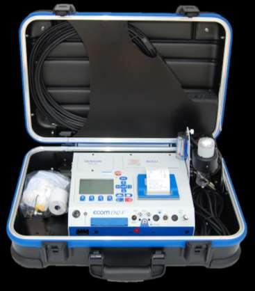
13 7. Analyzer startup 7.1 Carrying case & cooler When opening the case, make sure to pull out and up on the two tabs on the front. After the case is opened, unlock the cooler by pulling out on the knob and swinging the cooler 90deg upward. The cooler must be unlocked before the pump engages. 7.2 Sample line & probe Connect gas sample line, pressure line, and thermocouple as pictured: The fittings are sized so that you cannot switch the gas and pressure lines. Page 13
14 7.3 Analyzer startup The probe must be in fresh air when you start the analyzer! Press the red power button to turn on the analyzer. The main menu is displayed with 6 (or 7) menu options: Gas analysis Averaging Soot Test Data Processing Adjustments Control - Gas analysis : Perform gas analysis (see Chapter 8) - Averaging : Perform averaging test (see Chapter 11) - Soot test : Perform soot test/smoke dot test (see Chapter 10) - Data processing : Save snapshots to internal memory or perform data logging (only displays if MM card is inserted) (see Chapters 6 & 14) - Adjustments : Modify instrument settings (see Chapter 12) - Control : Check operation state of instrument (see Chapter 13) - Diagnostics : Only used with ECOM AK tool To perform measurements, select Gas analysis and confirm with <Enter>. The instruments starts a 1- minute auto-zero phase and the fuel types selection list is displayed. The following fuel types are available: Natural gas Butane Number 4 oil Coal North sea gas Page 14 Propane Number 2 oil Number 6 oil Wood Diesel oil Fuel type Natural gas CO2max A1 B Select:
15 8. Gas Analysis 8.1. Gas analysis display screen After the 1-minute auto-zero phase, the instrument switches over to the measurement mode. The gas measurement values can be viewed on 4 display pages. Press up/down to scroll between the pages. Standby <F1> O2 3.2 % CO % T.Gas 184 C T.Air 20 C BImSchV Edit line items on display <F4> Print values <F2> CO purge pump on/off <F3> Peltier cooler ON/OFF Note: To view readings with O2 correction, see Chapter 8.6 for instructions on how to change the units to O2-corrected values. Pressing <F1> goes to Standby mode which turns the pump off. If you want to change the F1 key, go to Adjustments->Internal->F1 Hotkey. You can set the F1 key to: Soot test, Data processing, View memory, Display values, Fuel type, Efficiency (K), Internal, Adjustments. Press <F2> to print out the values simultaneously to their recording in the intermediate memory. Press <F3> to start the CO purge pump. This dashes out the CO reading on the display and introduces fresh air to the CO sensor to protect it from over ranging Note: The CO purge pump automatically activates when the CO ppm limit is exceeded usually set at 4000ppm. Page 15
16 8.1. Gas analysis display screen (continued) Pressing <F4> goes to Edit mode which allows the user to change the line items on the display screen. In Edit mode, the values on the screen can be changed to what the user wants to see. To change these values, press F4 and you should see the 1 st line start blinking: - select line you would like to change with Up/Down it will blink - select parameter you would like to see with Right/Left - repeat until the display screen shows what you want it to - press F4 to accept changes 8.2 Inserting the probe To control for thermal drift, start the analyzer and let it acclimate to ambient temperature for minutes, then restart the analyzer before testing. O2 3.2 % CO % CO 0 ppm Eff % Losses 7.5 % Exc. air 1.18 T.Gas 184 C T.Air 20 C BImSchV Core stream search Connect the sampling tubing on the instrument to the sample gas inlet. Position the sampling probe in the exhaust channel, so that the thermocouple is fully surrounded with the gas (see below). Gas stream Probe tip Thermocouple hook Page 16
17 8.2 Inserting the probe (continued) Perform the measurement in the core stream of the exhaust gas channel (probe placed in the hottest gas temperature area). A trend indication for T.Gas lets you know whether the temperature is increasing or decreasing so that you can find the core stream. As long as the display shows an up arrow, it means the probe tip is moving towards the core stream center. If a down arrow is shown, it means you have moved the probe away from the core stream and the temperature is decreasing. If no temperature change is shown for at least 3 seconds, the trend indication will disappear. 8.3 Calculations: CO2, Efficiency, Losses, Excess air, & Dew point CO 2, efficiency, losses, excess air and dew point are calculated values. They can only be calculated if realistic values for the basic parameters like O 2 and the temperatures are available. In order for the calculations to appear, the O2 must be below 20.5% and the difference in gas temp and ambient temp must be at least 5 : O 2 < 20.5 % and T.Gas - T.Air > + 5 C The dew point can only be calculated accurately if, in the menu "Adjustments", the current barometric air pressure value has been inputed. If the gas temperature falls below the dew point (between 25 and 65 C), the efficiency will be calculated with condensation. In this case a (K) is displayed after Efficiency. 8.4 Taking a measurement: Ramp up, measure, & purge The analyzer takes a little time to ramp up, which allows for gas transport time and the build-up of a stable electrochemical reaction on the sensors. This time period lasts approx. 1 to 1.5 minute. Be sure to wait until the values are stable. If deviations higher than 2 ppm still occur by the gas values, they can be due to unstable pressure conditions in the exhaust channel. Page 17
18 If the measurement values are stable, press the Save Button (number 6) to transfer the values in the internal memory or F2 to print Printing Press F2 to print the values on the screen. To use the Printer button (number 6 on the keypad), you have to press the Save button (number 7 on the keypad) before pressing the Printer button. Measurement stored in intermediate memory Inserting Text onto the Printout If you want to insert text onto the printout, press Enter while in Gas Analysis, select Insert Text, press up/down to select the line, and press Enter again to start entering text. When done, press F1 to accept the text, then press ESC until you are back in Gas Analysis. Each time you print from now on, the text will appear on the printout. To delete the text, press Enter while in Gas Analysis, select Insert Text, press up/down to select the line, and press Enter again to start editing the text. Press F4 to get the cursor up to the text line, scroll right until the blinking cursor is beyond the last character, then press F2 until all characters are cleared. When done, press F1 to accept the text, then press ESC until you are back in Gas Analysis. No text will print out until the next time you insert text. 8.6 O2 Correction/Reference O2 O2 correction is commonly used by regulatory agencies to normalize CO and NOx values to a specific O2 percent (usually 3% or 15%). This allows for an apples to apples comparison when looking at emissions data from many different pieces of equipment with many different excess air values. Go to Adjustments -> Ref. O2 and enter the desired O2 correction value using the numbered buttons. Page 18
19 Now go to Adjustments -> Units and press up/down or right/left to change the unit to %O2 undiluted. Your units have been changed and you can return to Gas Analysis to view the corrected readings. 9. Draft/Pressure A trend indication for the draft/pressure conditions in the exhaust channel can be viewed during the gas analysis. However, the draft/pressure value will not be on the printout until you zero the sensor. To record a pressure measurement, follow these steps: While in Gas Analysis, scroll through the pages until you get to this one shown below. The pump will turn off. Disconnect the draft hose from the instrument and press F4 to zero the pressure sensor. The sensor is now calibrated. Reattach the draft hose, wait for the reading to appear, and press the Save button (number 6) to record the measurement. Now when you press F2 (whether in this menu or within other Gas Analysis pages), you will see the draft print out along with the gas readings. Pressure Draught hpa Recorded value: hpa 10. Soot test The Soot test allows you to enter up to 3 soot test measurements. Soot test Boiler temp. : 66 C 1.Soot meas. : Soot meas. : Soot meas. : -.- Oil trace : ---- Select : You must first turn on the probe heater so that the sample is maintained above dew point, preventing any condensation in the probe which can affect the filter paper. The filter paper slot is heated up to approx. 70 C. Go to Adjustments / Internal / Probe heating / F1. -Return to Soot test. -Insert a filter paper in the paper slot. Page 19
20 -Select the line 1st. Soot meas.. -Press <Enter> to start the measurement. The analyzer will pull 1.63 liters of sample gas. -Release the filter paper from the probe slot. 10. Soot test (continued) -Compare the greyness to your soot test chart (0-9). -Input the result using the numerical keys and press <Enter>. -Repeat this procedure until all 3 soot tests are completed. The average value will be calculated and automatically stored. -Go back to Gas Analysis and press F2 to print off soot test results. -Go to Adjustments / Internal / Probe heating / F4 to turn off the probe heater. You do not need to input Boiler temp. or oil trace if not needed. Let the probe cool down before putting back into the carrying case. 11. Averaging The averaging feature allows you to collect snapshots in a timed interval and calculates the average over a set time period. For instance, if you want to take 1 measurement per minute over a 5 minute period, you can set up the Averaging test to automate this. 1. Select Averaging within the main menu 2. Select Meas. Time Input total measuring time in minutes or seconds (for seconds, press decimal 1st) 3. Select Scanning Input interval time (for seconds, press decimal 1st) Mean values Start measurement Measurement time Scanning Printer Store Select : For example: If the Meas. Time is 5 minutes and the Scanning time is 60 seconds or 1 minute, the mean value will take into account 5 scans and find the average. Page 20
21 11. Averaging (continued) 4. Select Printer Select No Value to print only the final average values Select Each value to print all recorded snapshots along with the final average Select Each value of 2 to print every other recorded snapshot, etc. 5. Do not select Store. Please leave to default setting. 6. Select Start Measurement Mean value measurement has initiated Press up/down to toggle between mean value and real-time results 7. After the Meas. Time has elapsed, press 6/Printer key to print results 8. Press ESC, select Mean Value, and press F1 to quit mean value calculation 12. Adjustments Additionally to those ecom-en2-f functions described previously, various adjustments can be made in the instrument. From the main menu, select the sub-menu "Adjustments" and confirm with <Enter>. A selection of modifiable parameters, adjustable according to the application, is displayed. Place the cursor on the desired line and press <Enter> to call up or modify the adjustment. The modifiable parameters are: Unit (adjustment with cursor keys): - Calculation of gas concentrations in: Units Ref. O2 Fuel type Air pressu Select Adjustments : Set clock Paper feed Internal - ppm = volume concentration (parts per million) - mg/m 3 = mass concentration per volume unit - mg/kwh (undiluted) = mass concentration per power unit w/ O2 correction - mg/mj (undiluted) = mass concentration per power unit w/ O2 correction Page 21
22 12. Adjustments (continued) - ppm (undiluted) = volume concentration (parts per million) w/ O2 correction - mg/m 3 (undiluted) = mass concentration per volume unit w/ O2 correction Undiluted: Conversion of the gas concentration on selected reference oxygen: - mg/kwh and mg/mj are always calculated on 0% O 2 basis - Conversion formula E ref = E meas * 21 - O 2ref 21 - O 2meas O 2 reference (for ppm und mg/m 3 - Input after pressing <Enter>): - Input of O 2 reference value O 2 ref Fuel type (press <Enter> to access selection list): - Modification of adjusted fuel type (e.g. by measurements at combi-plants) Air pressure (press <Enter> to access menu): - Input of barometric air pressure for dew point calculation Clock set (press <Enter> to access setting menu): - Correction of internal clock with cursor keys Paper feed (press <Enter> to activate paper feed Internal (press <Enter> to open menu): - Further instrument settings: - See next page Page 22
23 12. Adjustments (continued) Printout contrast (0..9) (press <Enter> to access input menu): - Printer contraste adjustment Display contrast (press <Enter> to access input menu): - Display contraste adjustment with cursor keys Key beep (<F1> for YES / <F4> for NO): - The analyzer beeps each time a button is pressed Probe heating (<F1> for YES / <F4> for NO): -Turn on probe heating for the soot test -Turn on probe heating if a large portion of the probe is outside of the exhaust channel to prevent condensation in the probe pipe Language: English (change with <Enter>): - Info about selected language (3 languages selectable) F1 Hotkey (selection after pressing <Enter>): - Modification of adjusted menu the programme will open after pressing <F1> F4 Hotkey (selection after pressing <Enter>): - Modification of adjusted menu the programme will open after pressing <F4> Efficiency (C) (<F1> for YES / <F4> for NO): - Efficiency calculation with or without condensation gain Internal Print contrast Displ. contrast Key beep Language: English Select: F1 Hotkey F4 Hotkey Eff. (C) CO-Automatic USB Bluetooth Pitot-factor Printout CO-Automatic (<F1> for YES / <F4> for NO): - Adjustment for CO purging - YES = CO sensor switchs on after purging automaticaly - NO (default) = CO sensor has to be switched on with <F3> after purging Page 23
24 12. Adjustments (continued) USB (selection after pressing <Enter>): - Press up/down to change baud rate - Press right/left to change protocol Bluetooth (selection after pressing <Enter>): - Press up/down to change baud rate - Press right/left to change protocol With first use of the Bluetooth connection to PC type in password 0000 or 1234! Pitot factor (selection after pressing <Enter>): - Input of Pitot factor for flow rate calculation (standard = 0.93) Printout (selection after pressing <Enter>): - Text input for printout on measurement protocol (8 x 24 characters) - Input the text of line 1 as follows: 1. Activate character selection list with <F4>. 2. Select keyboard type with <F3> (4 different keyboards available). 3. Use the cursor keys to select the desired character (selected character is outlined by black background). 4. Confirm selection while pressing <Enter>. 5. Repeat procedure until desired text is complete. 6. Once input for line 1 is completed, deactivate the characters selection mode with <F4> and move to the second line with the cursor key <Down>. 7. Once all lines have been processed as desired, exit the menu with <ESC>. Page 24
25 13. Control The electrochemical sensors for gas analysis are submitted to a wearing process and do age. They alter their output values along the time depending on the gas concentration, the exposure time and the soiling grade of the sampled gas. The programme monitors the sensors and corrects drifts. But if the drifts and the correlated measurement errors increase, an error message is displayed. In this case the corresponding sensor must be changed by an authorised service centre. The control menu informs about the current status values for the sensors. Further information is also consigned on 2 display pages (use cursor keys to scroll): - accu voltage (charging status); is displayed as a symbol in all menus: Full charge Half charge Empty O mv CO 7 mv Accu 6.09 V - operation hours since last service - total operation hours - date of the next recommended service - phone number of the next service center - software version - serial number - amount of CO switch-offs - error amount Operation hours : 8.45 hrs Total : hrs Next unit check : Service tel. : Further pages: Program version :V Serial no. :EN CO purges : 15 Error counter : 21 Operation hours : 8.45 hrs Total : hrs Next unit check : Service tel. : Further pages: Page 25
26 14. Data Processing In order for this menu to appear, a memory card (32MB to 2GB) must be inserted into the analyzer. Note: This section explains how to save data snapshots to internal memory. For data logging onto a memory card, see 6. Data Logging onto Memory Card Select: Search or create files to save the data snapshot Data processing Select View Memory (M) Format Quit with: ESC DRT <-> PC! Datalogger View: View data files that have been saved Memory (M): Here all stored measurements (sorted by record number) can be viewed. Single measurement results can be called up as follows: - Select desired record number with the cursor keys and confirm with <Enter> - Scroll with the cursor keys - Press <ESC> to exit Date Fuel type :01 Fuel oil :02 Fuel oil :04 Fuel oil :07 Fuel oil :11 Fuel oil :23 Fuel oil :44 Fuel oil :53 Fuel oil Select : Format: If your memory card is not working properly, you may have to reformat. Caution: If you reformat, all files on the memory card will be lost! DRT <-> PC!: Load data: Enables the data import from e.g. rbr software (available on our website See Technical Data at the end of this manual for data format information (please observe the transfer options of your software!). Page 26
27 14. Data Processing (continued) Proceed as follows: -Connect ecom-en2-f and PC via USB cable. -Select Load data and confirm with <Enter>. -Answer the displayed question with YES (<F1>). -Decide if the data recorded can be cancelled (<F1> for YES / <F4> for NO). -Start the data transfer on your PC. Send data: With this function the data records completed with measurement values can be transferred to the PC programme (procedure similar to chapter Load data ). 15. Delta-T Measurement (Option) With the ecom-en2-f a difference temperature measurement is possible. For measurements at pipings (e.g water-in and water-out of heating systems), special temperature sensors are needed, available from your authorised rbr agency. Out of the main menu point "Diagnostics" select the sub-menu "dt measurement" and confirm with <Enter>. The instrument indicates the temperature T1 (sensor at connection Gas temperature ), the temperature T2 (sensor at connection Air temperature ) and the difference between both temperatures (T1 - T2). Press <Memory> to store the result in the intermediate memory. A printout can be started with <Print>. dt measurement T C T C dt 14.1 C Measurement stored in intermediate memory Page 27

28 14. Maintenance Tips Do not use other sensors or feelers from other manufacturers otherwise the TÜV / DIN EN approval will not be valid anymore! To secure the accuracy of your measuring instrument we recommend the annual check by an authorized ecom partner. In the case of strong demand (e.g. permanent several hours of measurement per day, rough conditions etc.) shorter intervals between checks should be selected - please contact your ecom partner. All ecom partners are listed under Service made by service centres non-authorised by rbr Messtechnik GmbH will result in a complete and immediate lost of any warranty! The following advices will be of help for the daily check and maintenance of single parts or assemblies: Fine dust filter Screw off the cover of the condensate trap/gas cooler and check the state of the particle filter. Change it once the filter has a grey colour (= number 2-3 of the soot comparison scale). Fine dust filter Page 28
29 Prefilter The prefilter made of high-grade steel is within the condensate container. It should be cleaned when contamination (with warm water and dry). Unscrew condensate container and prefilter. Assemble after cleaning again in reverse order. Prefilter Sensors The sensors get calibrated with the reference gas fresh air by each switch-on. Their state is permanently checked by the instrument. New sensors age along the operation time because of the wearing of the reagents (oxygen sensor) and due to soiling respectively exceeding concentrations beyond the nominal measurement range (toxic sensors). The output values of the sensors are (menu "Control"): O 2 approx mv Others 0 mv (+/- 150) If an error message is displayed during calibration and cannot be eliminated despite several calibration phases, so the instrument must be checked by a qualified and authorised service centre. The oxygen sensor must show a value of >7000 mv, otherwise it must be changed by an authorised service centre. The CO sensor is protected against exceedings by the internal programme. If the limit value of 4000 ppm is exceeded, a second pump switches on and flows the sensor with fresh air. After sufficient purging time (X behinds CO disappears) the sensor can be reintegrated into the measurement system with <F3> (if you choose Yes at Adjustments / Internal / CO-Automatic the CO sensor switchs to measurement automaticaly). The sensor can also be manually be excluded from the measurement system with <F3>. Page 29

30 Probe and tubing Depending on the frequency of use, probe and tubing should be regularly cleaned in order to release particle deposits and to prevent early wearing due to corrosion. - Release the connections at the instrument and at the probe grip to free the tubing. - Clean it (flow warm water in then dry respectively blow water drops out. - Slightly grease the O-rings of the tubing connections from time to time with acid-free grease. Change printer paper roll - Release the printer cover (press lock downwards). - If necessary, extract the paper rest out of the printer. Hereto select "Adjustments"/"Paper feed"/<enter>). - Remove the plastics tube of the previous roll. - Insert the paper end in the slot under the transport roll (paper roll inner side facing you while inserting the paper). - Convey approx. 3 cm paper thru the printer ("Adjustments"/"Paper feed"/<enter>). - Lay the paper roll in the corresponding hollow. - Insert the paper thru the slot of the printer compartment cover and close the latest. Unlocking printer cover Page 30
31 15. Technical Data Parameter Range Principle O vol-% Electrochemical CO ppm Electrochemical NO (option) ppm Electrochemical NO 2 (option) ppm Electrochemical SO 2 (option) ppm Electrochemical CO% (option) ppm Electrochemical CO CO 2max Calculation T-Gas C NiCr/Ni T-Air C Semi-conductor Differential pressure /- 100 hpa DMS bridge Efficiency % Calculation Losses ,9 % Calculation Excess air 1... Calculation CO undiluted (adjustable ref. O 2 ) Calculated Flue gas dew point Calculated Op. Temp: F Power supply Protocole printer Indication Dim. (W x H x D) Weight Mains power 230 V / 50 Hz~;Accu 6 V / 4,6 Ah integral; 58 mm paper width Printout individually programmable graphic display; backlit 430 mm x 170 mm x 380 mm approx. 7 kg complete with sampling system Subject to technical changes V1.8 / rbr Messtechnik GmbH Am Grossen Teich 2 D Iserlohn Telefon: +49 (0) Telefax: +49 (0) Internet: info@rbr.de Page 31
32 16. FAQ Where do I find important instrument information? How long is the life span of the sensors? Which sensors can I exchange? The instrument shows the error message O 2 sensor 0 mv! The instrument shows the message Check required! The instrument shows the error message T-Gas oder T-Air! The instrument shows wrong or inaccurately CO 2 values! IIn the menu Control all important instrument informations are shown (e.g. accu voltage, sensor values, unit number, next service date, operation hours etc.). With the arrow keys stands you can switch to the second page. The life span depends on the operating hours and the instrument equipment. The life span of the toxic sensors (CO, NO, SO 2, NO 2 ) is affected by high gas concentrations and a not sufficient purging. The life span for these sensors amounts to on the average between 4 and 6 years. The life span of the O 2 sensor is independent of the operating hours and amounts to approx. 2 years. The following sensors are exchangeable: - O 2 sensor - CO sensor (pre-calibrated) - NO sensor (pre-calibrated) - SO 2 sensor (pre-calibrated / only together with CO sensor The sensor must be renewed. This message appears automatically every 12 months or after 250 operating hours. Note: This is a recommendation to let check the instrument. The instrument is however still ready for use. Possible reasons could be: - Cable is broken (at the plug) - T-Air sensor is broken - Thermocouple is broken - Cable is defective Note: The error messages can be ignored at the EN2-F by pressing Enter. Calculations that depents on these temperatures are not implemented. Possible reasons could be: - O 2 is defective (CO 2 values are calculated from the O 2 values) - Pump is not working correctly - Leakage in the gas way - condensate trap / gas cooler is clogged Page 32
33 My instrument cannot be switched on! My instrument does not print! Can I change the printout? - Please check the mains cable - Please check the fuse - Please check mains connection (Plug socket switched on?) - Please load the accumulator min. 8 hours (Accumulator could be over-discharged) Please check whether the printer paper is correctly inserted. The thermal printer writes only on the thermally sensitive side. Please use always the correct paper for the printer, you will prevent defects at the printer. Please make sure that the printer is clean (no chads in the drive). You can change the printout (Menu: Adjustments). Hint: If you have several instruments of the same type, you can locate an error by exchanging the accessories (probe, hose, temperature sensor etc.). If further questions or problems should arise, please contact the next authorised service centre. Page 33
34 19. Calibration Procedure For best results, the calibration gas concentration should be as close to the expected levels of emissions as possible. Because each sensor is linear through a nominal range, one calibration gas concentration can be used for a reasonably wide range of emission levels. Fully charge analyzer: Place unit on charge the night before you plan to use analyzer to ensure full charge of battery. Turn on analyzer and let warm up: Switch on analyzer. Select Gas Analysis on main menu. Select Fuel Type and press OK. Select No for Data Processing (if prompted). Instrument will complete auto-zero sequence. Let the analyzer run for 15 minutes to acclimate to ambient temperature. This is very important, as the accuracy of electrochemical sensors is dependent on a proper temperature setting. Switch off the analyzer and switch back on. Go to Gas Analysis mode. The instrument will complete auto-zero based on the proper temperature. Calibrate your analyzer: 1. Select Control on the main menu. Swipe calibration magnet over the Cal Magnet sticker, located above the ESC button. The analyzer is now in calibration mode. You will see real-time readings on the screen. 2. Connect calibration hose from the regulator to the gas inlet (O2/CO) on the analyzer. a. If you are using an on demand regulator, connect it to the gas bottle and open gas bottle valve completely. The regulator will hold back the flow of gas until connected to the analyzer. b. If you are NOT using an on demand regulator, adjust the flow to match the analyzer pump draw. Page 34
35 19. Calibration Procedure (continued) 3. You must check for air leaks before calibrating. Apply a gas with 0% O2 to check for air leaks (ECOM service dept. uses NO gas balanced in N2). Flow calibration gas for 3 minutes. Check that O2 reading is 0.0%. If it is reading other than 0.0 %, turn off gas and troubleshoot the source of air leak. Do not proceed to calibrate analyzer until air leak is corrected. 4. If there is no air leak, allow gas to flow for another 2 minutes (total of 5 minutes). After the reading has stabilized, press up/down to place the arrow beside the target sensor and press OK to go to input mode. Input concentration of calibration gas using numbers on keypad. Press OK. The sensor has now been calibrated. 5. Allow the gas to flow for another seconds. If it does not drift more than 2% of the span gas, the calibration is steady and you may disconnect the gas. (If it does drift more than 2%, allow the reading to stabilize and reset calibration. If this still doesn t work, call ECOM.) 6. If calibrating more than one sensor, disconnect the regulator and reconnect to the next gas cylinder. Then flow calibration gas for 5 minutes, input calibration setting, & repeat step After all sensors have been calibrated, disconnect gas and allow the analyzer to flush with fresh air for 10 minutes or until readings are below 10 ppm. Questions? Call ECOM at Page 35
36 20. Memory Card Data Description of data record ecom-en2-f with Multi Media Card Format data logger records: J2KDL-xx.csv (separation mark between values = comma) Format punctual measurements: J2KDV.txt (separation mark between values = comma) Column Description Remark / Example A Date DD.MM.YYYY (also US-Version) B Time HH:MM:SS (also US-Version) C O2 in vol.% 0,0-21,0 D CO in ppm E NO in ppm F NO2 in ppm G SO2 in ppm H CO converted* I NO converted* J NO2 converted* K NOX converted* L SO2 converted* M T.Gas in C or F (US-Version with other range in F) N T.Air in C or F 0-99 (US-Version with other range in F) O Draught in hpa 0,00-20,00 P CO2 in vol.% 0,0-25,0 Q Efficiency in % 0,0-120,0 R Losses in % 0,0-100,0 S Excess air > 1,00 T Dew point in C oder F (US-Version with other range in F) U Poisoning index > 0,0 V O2 (gas channel check) in vol.% 0,0-21,0 W CO (gas channel check) in ppm Related to 0,0 vol.% O2 X CO (gas channel check) in ppm Measured value Y O2 (O2 check) in vol.% 0,0-21,0 Z T.Boiler AA T.Sensor 0-99 AB O2 reference 0,0-21,0 AC Unit 0=ppm; 1=mg/m3; 2=mg/kWh; 3=mg/MJ AD Norm N = converted to O2 ref. AE Fuel type number Index acc. to instrument table AF Fuel type text Text acc. to instrument table AG Soot 1 0,0-9,9 AH Soot 1 0,0-9,9 AI Soot 1 0,0-9,9 AJ Oil trace 0=no; 1=yes; AK 20 characters text AL 20 characters text AM 16 characters text AN Serial number AO CO (O2 check) in ppm AP Zug (O2 check) in hpa AQ CxHy AR Number copy data AS T1 (deltat-measurement) AT T2 (deltat-measurement) AU Velocity m/s AV CO Enviroment CH-version = Kind of control AW free CH-version = Load range AX Comment text AY Comment text AZ Comment text BA Comment text BB H2 in ppm CH version = Oil consumption BC H2 converted* CH version = Thermal output BD Sensor 6 in ppm CH version = Operation hours counter BE Sensor 6 converted * CH version = Code Page 36
37 BF dp (velocity) in Pa ,00 BG Air pressure in hpa BH Unit 2 0=ppm; 1=mg/m3; 2=mg/kWh; 3=mg/MJ; 4=ppmN; 5=mg/m3; 6=--- BI CO (Unit 2) BJ NO (Unit 2) BK NO2 (Unit 2) BL NOx (Unit 2) BM SO2 (Unit 2) BN Analogue input 1 BO Analogue input 2 BP Sensor 7 in ppm BQ Meas. gas volume in l/min BR last column 0 * converted to unit (column AC) and converted on O2 ref. (Column AB) when column AD = N Page 37
38 Calibration log Date: Cal gas concentration Sensor reponse after 5 min CO NO NO2 Date: Cal gas concentration Sensor reponse after 5 min CO NO NO2 Date: Cal gas concentration Sensor reponse after 5 min CO NO NO2 Date: Cal gas concentration Sensor reponse after 5 min CO NO NO2 Date: Cal gas concentration Sensor reponse after 5 min CO NO NO2 Page 38
39 Date: Cal gas concentration Sensor reponse after 5 min CO NO NO2 Date: Cal gas concentration Sensor reponse after 5 min CO NO NO2 Date: Cal gas concentration Sensor reponse after 5 min CO NO NO2 Date: Cal gas concentration Sensor reponse after 5 min CO NO NO2 Date: Cal gas concentration Sensor reponse after 5 min CO NO NO2 Page 39
 326-6411 PHONE (770)")
40 RUGGED. RELIABLE. ACCURATE. ECOM AMERICA LTD 1628 OAKBROOK DRIVE GAINESVILLE, GA TOLL FREE (877) PHONE (770) FAX (770) Page 40
Operating Instructions
 Operating Instructions Index Page Important Hints 3 1. Instrument Design 5 2. Remote monitor ecom-r 7 3. Gas Cooler (option) 9 4. Power Supply 10 5. Data Memory 10 6. Instrument Start 11 7. Input or Selection
Operating Instructions
 Operating Instructions Index Page Important Hints 3 1. Instrument Design 5 2. Switch on Instrument 6 3. Choose a storage location (option) 7 4. Gas Analysis 4.1. Measurement Preparations 8 4.2. Gas Analysis
OXY Integral. INTERCON ENTERPRISES INC Tel: Fax: Internet:
 OXY Integral INTERCON ENTERPRISES INC Tel: 800 665 6655 Fax: 604 946 5340 E-Mail: sales@intercononline.com Internet: www.intercononline.com Manual Integral 2006 1 INDEX 2-3 PREFACE 4 INTRODUCTION 5 Principle
OPTIMA 7 - BIOGAS Calibrating the gas sensors SENSOR ADJUSTMENT. Diamond Scientific 625 Peachtree St., Cocoa, Florida /Tel:
 SENSOR ADJUSTMENT The calibration of your OPTIMA 7 should be performed by experienced service personal only! MRU will not be responsible for any misuse or wrong interpretation of this calibration instruction.
Instruction Manual Dräger MSI P7 and MSI P7 plus
 Dräger MSI GmbH Rohrstraße 32 58093 Hagen Tel.: +49-2331 / 9584-0 Fax: +49-2331 / 9584-29 e-mail: info@draeger-msi.de D 923; Edition 2011-01-01 Content 1. General Hints Page 4 2. The Instrument 2.1 Front
Instruction Manual Dräger MSI EM200 + EM200-i
 Dräger MSI GmbH Rohrstraße 32 58093 Hagen Tel.: +49-2331 / 9584-0 Fax: +49-2331 / 9584-29 e-mail: info@draeger-msi.de 5695019; Edition 2012-04-13 Content 1. Reference notes Page 4 1.1 Approvals 1.2 Information
ECOM EN2-F PARTS LIST PART PART NUMBER DESCRIPTION
 ECOM EN2-F PARTS LIST PART PART NUMBER DESCRIPTION Water Trap Filter (10/PK) 3015840G 10/PK - Particulate filter located on top of water trap assembly In-line Smoke Filter Standard(1 EACH) 7118501H 1 EACH
MEGAS 2.0. Gas analysis with direct C-Level Calculation and Bus-Connection. Data sheet
 Data sheet MEGAS 2.0 Gas analysis with direct C-Level Calculation and Bus-Connection Mesa Industrie-Elektronik GmbH Neckarstraße 19, D-45768 Marl info@mesa-gmbh.de +49 (0) 2365-97 45 1-0 +49 (0) 2365-97
ecom-en2-f PARTS LIST PART NUMBER
 ecom-en2-f S LIST Water Trap Filter (10/PK) 3015840G $39.00 10/PK - particulate filter located on top of water trap assembly In-line Smoke Filter Standard(1 EACH) 7118501H $7.00 1 Each - standard 3/4"
Columbus Instruments
 0215-003M Portable O 2 /CO 2 /CH 4 Meter User s Manual Columbus Instruments 950 NORTH HAGUE AVENUE TEL:(614) 276-0861 COLUMBUS, OHIO 43204, USA FAX:(614) 276-0529 1 www.colinst.com TOLL FREE 1-800-669-5011
Using the UltraRAE. Firmware 2.35
 Using the UltraRAE Firmware 2.35 Training Agenda UltraRAE features Setting up the UltraRAE Turning on the UltraRAE Idle Operation RAE-Sep Tubes Prepping for a measurement Taking a measurement Alarm modes
OxyScan Graphic. Operating Instructions. UMS Micro-oxygen sensor 501. Microprocessor instrument
 OxyScan Graphic Operating Instructions UMS Micro-oxygen sensor 501 Microprocessor instrument Introduction Thank you for choosing the UMS Micro Oxygen Sensor 501 - a highly advanced product! Please read
Bante820 Portable Dissolved Oxygen Meter Instruction Manual
 Bante820 Portable Dissolved Oxygen Meter Instruction Manual BANTE INSTRUMENTS CO., LTD Bante820 Portable Dissolved Oxygen Meter 1 Introduction Thank you for selecting the Bante820 portable dissolved oxygen
Bante821 Portable Dissolved Oxygen Meter Instruction Manual
 Bante821 Portable Dissolved Oxygen Meter Instruction Manual BANTE INSTRUMENTS CO., LTD Bante821 Portable Dissolved Oxygen Meter 1 Introduction Thank you for selecting the Bante821 portable dissolved oxygen
Met One E-BAM Particulate Monitor
 STANDARD OPERATING PROCEDURES Met One E-BAM Particulate Monitor AMBIENT AIR MONITORING PROGRAM for the 130 LIBERTY STREET DECONSTRUCTION PROJECT LOWER MANHATTAN DEVELOPMENT CORPORATION 1 Liberty Plaza
BIOGAS COMBUSTION PLANT MAINTENANCE MANUAL
 BIOGAS COMBUSTION PLANT MAINTENANCE MANUAL (PLANT MAINTENANCE MANUAL) Puente Gallego Landfill, Rosario (Argentina) ARIA.BIZ S.A. Montevideo 589, 7 floor 1019 Capital federal Argentina Tel: +54 11 5171
Pegas 4000 MF Gas Mixer InstructionManual Columbus Instruments
 Pegas 4000 MF Gas Mixer InstructionManual Contents I Table of Contents Foreword Part I Introduction 1 2 1 System overview... 2 2 Specifications... 3 Part II Installation 4 1 Rear panel connections...
CONSOLE-320 ENGLISH. 230A: CONSOLE-320 with cable data output Item 230B: CONSOLE-320 with cable + wireless radio data output
 CONSOLE-320 Item 230A: CONSOLE-320 with cable data output Item 230B: CONSOLE-320 with cable + wireless radio data output Table of contents 1. INTRODUCTION...2 1.1 Power supply...2 1.2 Connections...2 1.3
Bante810 Benchtop Dissolved Oxygen Meter Instruction Manual
 Bante810 Benchtop Dissolved Oxygen Meter Instruction Manual BANTE INSTRUMENTS CO., LTD Bante810 Benchtop Dissolved Oxygen Meter 1 Introduction Thank you for selecting the Bante810 benchtop dissolved oxygen
The HumiSys. RH Generator. Operation. Applications. Designed, built, and supported by InstruQuest Inc.
 The HumiSys RH Generator Designed, built, and supported by InstruQuest Inc. Versatile Relative Humidity Generation and Multi-Sensor System The new HumiSys with single or dual RH probes capabilities is
DOscan10 Pocket Dissolved Oxygen Tester Instruction Manual
 DOscan10 Pocket Dissolved Oxygen Tester Instruction Manual BANTE INSTRUMENTS CO., LTD DOscan10 Pocket Dissolved Oxygen Tester 1 Thank you for selecting the DOscan10 pocket dissolved oxygen tester. This
Manual of SF6 Comprehensive Tester
 Manual of SF6 Comprehensive Tester Important Description All the staff taking in charge of the usage or maintenance of this product should carefully read this manual. The same as any other complicated
UNITY 2 TM. Air Server Series 2 Operators Manual. Version 1.0. February 2008
 UNITY 2 TM Air Server Series 2 Operators Manual Version 1.0 February 2008 1. Introduction to the Air Server Accessory for UNITY 2...2 1.1. Summary of Operation...2 2. Developing a UNITY 2-Air Server method
In Response to a Planned Power Outage: PPMS EverCool II Shut Down and Re-start Procedure
 PPMS Service Note 1099-412 In Response to a Planned Power Outage: PPMS EverCool II Shut Down and Re-start Procedure Introduction: Loss of electricity to the PPMS EverCool II should not cause damage to
Technical Data Sheet MF010-O-LC
 Technical Data Sheet MF010-O-LC - 1 - 1. Properties The oxygen measuring system MF010-O-LC determines the oxygen content in gas mixtures up to a temperature of 250 C. It is particularly suitable for the
OPERATOR S MANUAL Ar-Gone Weld Gas Analyzer
 July 2011 OPERATOR S MANUAL Ar-Gone Weld Gas Analyzer WARNING! Before operating this product, read and understand this Operator s Manual. Become familiar with the potential hazards of this unit. Contact
Automatic Isokinetic Sampler. ST5 Evo
 Automatic Isokinetic Sampler ST5 Evo Automatic Isokinetic Sampler ST5 Evo Moreover, in case of pump failure, the CU can work with a spare Dado PU unit or with any pump capable to supply the needed flowrate,
KANE455. Flue Gas Analyser with direct CO 2 measurement. Stock No: October Kane International Ltd
 KANE455 Flue Gas Analyser with direct CO 2 measurement Stock No: 18859-7 October 2012 Kane International Ltd CONTENTS Page No: KANE455 Overview 4 ANALYSER LAYOUT & FEATURES 5-6 1. BATTERIES 7 2. BEFORE
KERN EG/EW Version /02
 E KERN EG/EW Version 1.5 07/02 Operating Instructions Electronic Precision Balances Contents 1 TECHNICAL DATA... 20 2 UNPACKING AND STANDARD ACCESSORIES... 23 3 SETTING UP THE BALANCE... 23 4 EXTERNAL
Appendix D: SOP of INNOVA 1412 Photoacoustic Multi-Gas Monitor. Description and Principle of Operation
 Page 1 of 19 : SOP of INNOVA 1412 Photoacoustic Multi-Gas Monitor Description and Principle of Operation The photoacoustic multi-gas monitor (INNOVA 1412, Innova AirTech Instruments, Denmark) is a highly
RM-80 respiration monitor
 RM-80 respiration monitor User Manual September 18, 2015 0025-003M 950 North Hague Avenue Columbus, Ohio 43204-2121 USA Sales: sales@colinst.com Service: service@colinst.com Phone: (614) 276-0861 Fax:
CF8-W-Disp-CO. User manual. CO 2 / CO sensor with built-in general purpose controller
 User manual CF8-W-Disp-CO CO 2 / CO sensor with built-in general purpose controller General The IAQ-sensor product CF8-W-Disp-CO is used to measure indoor air carbon dioxide and carbon monoxide concentrations.
Hot extractive multi-channel gas analyser for continuous process and emissions monitoring.
 Product Data Sheet CODEL Continuous Emission Monitoring GCEM4100 Extractive Gas Analyser CO, CO2, NO, NO2, SO2, HCL, CH4 & H2O Hot extractive multi-channel gas analyser for continuous process and emissions
SDM-2012 Docking Station Standalone Configuration Operator s Manual
 SDM-2012 Docking Station Standalone Configuration Operator s Manual Part Number: 71-0254RK Revision: P5 Released: 10/5/12 www.rkiinstruments.com Warranty RKI Instruments, Inc. warrants gas alarm equipment
Portable Gas Monitor GX User Maintenance Manual (H4-0050)
") H4E-0050 Portable Gas Monitor GX-8000 User Maintenance Manual (H4-0050) Need of Maintenance and Servicing This gas monitor must be maintained in a normal state at all times to prevent accidents due to
H4E-0050 Portable Gas Monitor GX-8000 User Maintenance Manual (H4-0050) Need of Maintenance and Servicing This gas monitor must be maintained in a normal state at all times to prevent accidents due to
ACV-10 Automatic Control Valve
 ACV-10 Automatic Control Valve Installation, Operation & Maintenance General: The Archer Instruments ACV-10 is a precision automatic feed rate control valve for use in vacuum systems feeding Chlorine,
Atlas 6TM. Indoor Air Quality Monitor Instruction Manual. Measures CO 2, Temperature and Humidity DISTRIBUTED BY
 Atlas 6TM Indoor Air Quality Monitor Instruction Manual Measures C 2, Temperature and Humidity DISTRIBUTED BY INTRDUCTIN Thank you for purchasing this meter. This device measures ppm levels, temperature
JOLLY2. Installation user s manual. 6 different operating modes selectable. version 3.3. DATA TO BE FILLED OUT BY THE INSTALLER (Page 1)
") ENGLISH ENGLISH ENGLISH ENGLISH Installation user s manual Warning! electrical scheme modified JANUARY 2005 version 3.3 JOLLY2 DATA TO BE FILLED OUT BY THE INSTALLER (Page 1) 6 different operating modes
ENGLISH ENGLISH ENGLISH ENGLISH Installation user s manual Warning! electrical scheme modified JANUARY 2005 version 3.3 JOLLY2 DATA TO BE FILLED OUT BY THE INSTALLER (Page 1) 6 different operating modes
FTC130 Transmitter. Operating Manual
 Seite 1 von 11 FTC130 Transmitter Fast Thermal Conductivity Analyzer Operating Manual 1.09KD180724CWI1V05 Messkonzept GmbH Seite 2 von 11 1. Intended Use... 3 2. Description... 4 3. Measuring gases and
Experiment AMe-1: Small Animal Respiratory Exchange Ratio (RER)
") Experiment AMe-1: Small Animal Respiratory Exchange Ratio (RER) Background There are two main sources of energy available for animal metabolism: carbohydrates (CHO) and fats. These molecules are broken
Experiment AMe-1: Small Animal Respiratory Exchange Ratio (RER) Background There are two main sources of energy available for animal metabolism: carbohydrates (CHO) and fats. These molecules are broken
MASSACHUSETTS STATE POLICE CRIME LABORATORY. Certificate of Calibration Procedure for the Alcotest 9510
 MASSACHUSETTS STATE POLICE CRIME LABORATORY Certificate of Calibration Procedure for the Alcotest 9510 Effective Date: May 10, 2017 Page 1 of 23 TABLE OF CONTENTS 1 INTRODUCTION... 3 2 ABBREVIATIONS...
Touch Screen Guide. OG-1500 and OG Part # T011
 Touch Screen Guide OG-1500 and OG-2000 Part # 9000000.T011 Effective 11/2010 External View Internal View 1. Transducer Banks 2. Oxygen Sensor 3. PLC These are the two manifolds with three (3) transducers
A180 DO/BOD/OUR/SOUR Meter Instruction Manual
 A180 DO/BOD/OUR/SOUR Meter Instruction Manual BANTE INSTRUMENTS CO., LTD A180 DO/BOD/OUR/SOUR Meter 1 Introduction Thank you for selecting the A180 multiparameter dissolved oxygen meter. This manual provides
Instruction Manual. Biogas Analyzer InCa Bio 04
 Instruction Manual Biogas Analyzer InCa Bio 04 Instruction Manual InCa Bio 04 contents - IMPORTANT - Refer to the safety intructions before installation begins 2 Manual InCa Bio 04 07-10-10 R2 Table of
We measure it. For gas and water installers. testo hpa. bar
 Pressure measuring instruments For gas and water installers testo 312-2 hpa testo 312-3 testo 312-4 bar C testo 312-2 / testo 312-3 Pressure meters for gas and water fitters testo 312-2 testo 312-2, fine
Pneumatic high-pressure controller Model CPC7000
 Calibration technology Pneumatic high-pressure controller Model CPC7000 WIKA data sheet CT 27.63 Applications Healthcare and avionics industry Industry (laboratory, workshop and production) Transmitter
Pneumatic high-pressure controller Model CPC7000
 Calibration technology Pneumatic high-pressure controller Model CPC7000 WIKA data sheet CT 27.63 Applications Automotive and avionics industry Industry (laboratory, workshop and production) Transmitter
User's Manual. Heavy Duty Dissolved Oxygen Meter. Model
 User's Manual Heavy Duty Dissolved Oxygen Meter Model 407510 Introduction Congratulations on your purchase of Extech's Heavy Duty Dissolved Oxygen / Temperature Meter which simultaneously displays Dissolved
UsER manual for Watersens ph -REDOX
 UsER manual for Watersens -REDOX Cl 8 1 2 6 3 3 7 7 4 4 4 4 Parts List 1 Redox Probe 1 x 2 PH Probe 1 x 5 Tube Weight 2 x 6 Connection Valve 1 x chlorine 3 Chlorine and Pumps 2 x 7 Dosing Valve 2 x 5 5
Instructions for Assembly, Installation, and Operation of the Gas Addition Kit Accessory with the CEM Discover Systems
 Corporation Issued: 5/09 P/N: 600104 Rev. 2 Instructions for Assembly, Installation, and Operation of the Gas Addition Kit Accessory with the CEM Discover Systems The Gas Addition Accessory permits the
Race Screen: Figure 2: Race Screen. Figure 3: Race Screen with Top Bulb Lock
 Eliminator Competition Stand Alone Mode - Instruction Manual Main Menu: After startup, the Eliminator Competition will enter the Main Menu. Press the right/left arrow buttons to move through the menu.
Electronic Commissioning Unit. Instructions
 Electronic Commissioning Unit Instructions 1. The Comdronic AC6 Electronic Commissioning Unit 2. Health and Safety 3. Description of Unit 4. Connection and Set-up Procedure 5. Menu System a. Main Menu
Heavy Duty Dissolved Oxygen Meter
 User's Manual Heavy Duty Dissolved Oxygen Meter Model 407510 Test Equipment Depot - 800.517.8431-99 Washington Street Melrose, MA 02176 FAX 781.665.0780 - TestEquipmentDepot.com Introduction Congratulations
Hot extractive multi-channel gas analyser for continuous process and emissions monitoring.
 Product Data Sheet CODEL Continuous Emission Monitoring GCEM4100 Extractive Gas Analyser CO, CO2, NO, NO2, SO2, HCL, CH4 & H2O Hot extractive multi-channel gas analyser for continuous process and emissions
USER MANUAL. Intelligent Diagnostic Controller IDC24-A IDC24-AF IDC24-AFL IDC24-F IDP24-A * IDP24-AF * IDP24-AFL * IDP24-F * 1/73
 USER MANUAL Intelligent Diagnostic Controller IDC24-A IDC24-AF IDC24-AFL IDC24-F IDP24-A * IDP24-AF * IDP24-AFL * IDP24-F * *) Require software ID: DID-SW-001 1/73 Table of contents 1 General... 3 1.1
Best Practice Guide, Servomex 2700
 For full installations details refer to the. Best Practice Guide, Servomex 2700 Mounting: General Guidelines: Servomex 2700 Control Units and air supplies (utilities units) should, ideally, be mounted
Experiment AMe-1: Small Animal Respiratory Exchange Ratio (RER)
") Experiment AMe-1: Small Animal Respiratory Exchange Ratio (RER) Background There are two main sources of energy available for animal metabolism: carbohydrates (CHO) and fats. These molecules are broken
Experiment AMe-1: Small Animal Respiratory Exchange Ratio (RER) Background There are two main sources of energy available for animal metabolism: carbohydrates (CHO) and fats. These molecules are broken
User manual CF8-D/W-IN
 User manual CF8-D/W-IN General The sensor CF8-D/W-IN is used to measure the carbon dioxide concentration inside incubators. All functions can be modified from a PC with the communication cable. UMA 48
Alcotest Breath Alcohol Screening Device. Operator Instructions for Use. ST _sw.eps
 D Alcotest 6510 Breath Alcohol Screening Device Operator Instructions for Use ST-207-2004_sw.eps Contents Contents................................................. 2 For your safety............................................
Instruction Manual. BZ7002 Calibration Software BE
 Instruction Manual BZ7002 Calibration Software BE6034-12 Index _ Index Index... 2 Chapter 1 BZ7002 Calibration Software... 4 1. Introduction... 5 Chapter 2 Installation of the BZ7002... 6 2. Installation
Flow VA 520. incl. temperature measurement. Intelligent solutions for ac- for compressed air and gases R 1/4 (DN 8) DN 15 R 3/4 (DN 20) DN 25
 DN 15 R 3/4 (DN 20) DN 25") VA 520 incl. temperature R 1/4 (DN 8) DN 15 R 3/4 (DN 20) DN 25 R 1 1/4 (DN 32) DN 40 R 2 (DN 50) Intelligent solutions for ac- for compressed air and gases work according to the approved calorimetric
VA 520 incl. temperature R 1/4 (DN 8) DN 15 R 3/4 (DN 20) DN 25 R 1 1/4 (DN 32) DN 40 R 2 (DN 50) Intelligent solutions for ac- for compressed air and gases work according to the approved calorimetric
Manual Weighingblock VB2 series and Uniscale
 Manual Weighingblock VB2 series and Uniscale Note: At page 8 in this manual you will find a short form instruction. Normally the only instruction shipped together with the Scale. Overview different ranges.
TorMinal. Operating instructions V OCE-Rev.L_EN
 TorMinal Operating instructions 1-138 3800-20310V001-112016-0-OCE-Rev.L_EN Table of contents General Information... 4 Symbols... 4 General safety instructions... 4 Safety information for batteries... 4
STANDARD OPERATING PROCEDURES. Andersen Instruments Federal Reference Method (FRM) Ambient Particulate (PM 10 /PM 2.
 Ambient Particulate (PM 10 /PM 2.") STANDARD OPERATING PROCEDURES Andersen Instruments Federal Reference Method (FRM) Ambient Particulate (PM 10 /PM 2.5 ) Sampler (RAAS) AMBIENT AIR MONITORING PROGRAM for the 130 LIBERTY STREET DECONSTRUCTION
STANDARD OPERATING PROCEDURES Andersen Instruments Federal Reference Method (FRM) Ambient Particulate (PM 10 /PM 2.5 ) Sampler (RAAS) AMBIENT AIR MONITORING PROGRAM for the 130 LIBERTY STREET DECONSTRUCTION
Intelligent SUNTEX DC-5310(RS) Dissolved Oxygen Transmitter
 Dissolved Oxygen Transmitter") Intelligent SUNTEX DC-5310(RS) Dissolved Oxygen Transmitter Overview C % ppm 4~20mA Analog Output ppb Power Supply 100~240 VAC mg/l Dimensions 96 x 96 x 132mm RS-485 Digital Output (for DC-5310-RS only)
Intelligent SUNTEX DC-5310(RS) Dissolved Oxygen Transmitter Overview C % ppm 4~20mA Analog Output ppb Power Supply 100~240 VAC mg/l Dimensions 96 x 96 x 132mm RS-485 Digital Output (for DC-5310-RS only)
CO, NO, NO 2, NO x, SO 2, CH 4, HCl, CO 2 & H ² O. Extractive low cost, low maintenance devices for continuous process and emissions monitoring.
 Product Data Sheet CODEL Continuous Emission Monitoring GCEM 40 Series Extractive Gas Analyser CO, NO, NO 2, NO x, SO 2, CH 4, HCl, CO 2 & H ² O Extractive low cost, low maintenance devices for continuous
Mass Flow Controller (MFC) for Gases
 for Gases") Mass Flow Controller (MFC) for Gases Bypass MFC with capillary technology for nominal flow rates from 5 ml N /min to 15 l N /min Applicable for aggressive gases Compact design and digital communication
Mass Flow Controller (MFC) for Gases Bypass MFC with capillary technology for nominal flow rates from 5 ml N /min to 15 l N /min Applicable for aggressive gases Compact design and digital communication
Model EXAxt AV550G. Averaging Oxygen Analyzer
 Model EXAxt AV550G Averaging Oxygen Analyzer Oxygen Measurement and Flyash Oxygen % vs cell EMF The O2 mation, model AV550, averaging oxygen analyzer was designed with a focus Calibration 1 on practical
better measurement Simply a question of SCHMIDT Flow Sensor SS The cost-effective alternative in pressurised systems up to 10 bars.
 Simply a question of better measurement SCHMIDT Flow Sensor SS 20.261 The cost-effective alternative in pressurised systems up to 10 bars. Compressed air technology Industrial processes A cost analysis
MASK INTEGRITY TEST ACCESSORY (MITA) MODEL 8120
 MODEL 8120") MASK INTEGRITY TEST ACCESSORY (MITA) MODEL 8120 QUICK START GUIDE P/N 6006154, REVISION C MAY 2013 Model 8120 Mask Integrity Tester is patented under U.S. Patent No. 8,312,761. Additional patents are pending.
MASK INTEGRITY TEST ACCESSORY (MITA) MODEL 8120 QUICK START GUIDE P/N 6006154, REVISION C MAY 2013 Model 8120 Mask Integrity Tester is patented under U.S. Patent No. 8,312,761. Additional patents are pending.
Device overview. 6 Breathing circuit connection. Note: When the remote control foot pedal is connected, the manual switch is disabled.
 CoughAssist E70 Quick start guide 1 2 3 4 5 Device overview Starting therapy Modifying therapy settings Monitoring view and icons 6 7 Suggested guidelines for therapy Device menu Mask fitting 1 Device
Table of contents. Table of contents 1. Installation 2. Introduction ( Display, monitor ) 3. Introduction ( Operating elements ) 4
 3. Introduction ( Operating elements ) 4") Table of contents page 1 CONTENTS PAGE Table of contents 1 Installation 2 Introduction ( Display, monitor ) 3 Introduction ( Operating elements ) 4 Introduction ( Result interpretation) 5 Factory default
Table of contents page 1 CONTENTS PAGE Table of contents 1 Installation 2 Introduction ( Display, monitor ) 3 Introduction ( Operating elements ) 4 Introduction ( Result interpretation) 5 Factory default
HumiSys HF High Flow RH Generator
 HumiSys HF High Flow RH Generator Designed, built, and supported by InstruQuest Inc. Versatile Relative Humidity Generation and Multi-Sensor System The HumiSys HF is a high flow version of the previously
Operating Manual. SUPREMA Calibration. Software for Fire and Gas Warning Units. Order No.: /01. MSAsafety.com
 Operating Manual Software for Fire and Gas Warning Units Order No.: 10154656/01 MSAsafety.com MSA Europe GmbH Schlüsselstrasse 12 8645 Rapperswil-Jona Switzerland info.ch@msasafety.com www.msasafety.com
TC65M/15M TEMPERATURE CALIBRATOR USER S MANUAL
 TC65M/15M TEMPERATURE CALIBRATOR USER S MANUAL Thank you for purchasing a Scan-Sense temperature calibrator. The products are manufactured by Scan-Sense AS in accordance with our high quality standards
973-SF 6 Analyzer. Precise and Stable SF 6 Gas Analyzer REFLECTING YOUR STANDARDS
 Precise and Stable SF 6 Gas Analyzer Simultaneous measurement of humidity, SF 6 purity and SO 2 concentration Integrated gas recovery system with automatic pump back Fully automated SF 6 gas testing Fundamental
GasSense NDIR User Manual
 INDEX INDEX... 1 1. OVERVIEW... 2 2. TECHNICAL DATA... 3 3. SPECIFICATIONS... 4 4. PRODUCT DESCRIPTION... 5 4.1 Mechanical details... 5 4.2 Piping... 7 4.3 Connections... 7 5. INSTALLATION... 10 6. CALIBRATION
444C DUAL PERFORMANCE VALUE PACK
 (Chrome) PART NO. 44432 IMPORTANT: It is essential that you and any other operator of this product read and understand the contents of this manual before installing and using this product. SAVE THIS MANUAL
Gas Module for Series GMS800
 Title Page SUPPLEMENTARY OPERATING INSTRUCTIONS Gas Module for Series GMS800 Components Application Information Operating Data Document Information Described Product Product name: Gas Module Basic device:
Operating Instructions Part No
 DIGITAL AUTOMATIC TYRE INFLATOR Operating Instructions Part No. 11.0578 Thank you for selecting this Jamec Pem Automatic Tyre Inflator. Please read this manual before carrying out any installation or service
RAM 4021-DPX Operation Manual
 RAM 4021-DPX Operation Manual Worldwide Manufacturer of Gas Detection Solutions TABLE OF CONTENTS ABL 4021-DPX / RAM 4021-DPX For Your Safety... 3 Description... 3 Setup Mode... 4 Lights/Alarms... 4 Operation...
RAM Operation Manual
 RAM 4021-1 Operation Manual Worldwide Manufacturer of Gas Detection Solutions TABLE OF CONTENTS RAM 4021-1 For Your Safety... 2 Description... 2 Setup Mode... 3 Lights/Alarms... 3 Operation... 4 Calibration...
Scoreboard Operator s Instructions MPC Control
 Scoreboard Operator s Instructions MPC Control Some features on the keyboard overlay may not be included on the particular model being operated. Since 1934 Retain this manual in your permanent files 1/21/2011
When buying one of our prototypes you agree with this!
 This ppo2 display unit is just a prototype, using it is not allowed and not our intension. It is for demonstration only. Be always aware that a device like this can and will show wrong data and that can
HPICAL Operation & Data Logging Procedures. Click spacebar to advance through slides 1
 HPICAL-15000 Operation & Data Logging Procedures Click spacebar to advance through slides 1 WARNING Always wear proper safety equipment when using high pressure equipment. Do not exceed 125 psi air pressure.
Digital Vacuum Regulator
 Temperature Control for Research and Industry Digital Vacuum Regulator User s Manual Model 300 INDEX SECTION PAGE 1. QUICK OPERATING INSTRUCTIONS........................... 3 Safety Notices.................................................
User Manual. asense VAV. CO 2 / temperature sensor with built-in general purpose controller
 Gas and Air Sensors User Manual asense VAV CO / temperature sensor with built-in general purpose controller General The IAQ-sensor product asense VAV is used to measure indoor air carbon dioxide concentration
White Paper. Chemical Sensor vs NDIR - Overview: NDIR Technology:
 Title: Comparison of Chemical Sensor and NDIR Technologies TSN Number: 25 File:\\MII- SRV1\Metron\Bridge_Analyzers\Customer_Service_Documentation\White_Papers\25_G en EGA NDIR vs Chemical Sensor.docx Created
AUTOMATIC TIRE INFLATOR # MW-60, MW-60-4WAY & MW-64HP
 USER MANUEL AUTOMATIC TIRE INFLATOR # MW-60, MW-60-4WAY & MW-64HP TIRE EQUIPMENT MANUFACTURER 1.866.409.RACK WWW.MARTINSINDUSTRIES.COM info@martinsindustries.com PARTS Verify that the following components
Mass Flow Controller (MFC) for Gases
 for Gases") Mass Flow Controller (MFC) for Gases Type 8713 can be combined with... Direct flow measurement by MEMS- Technology for nominal flow rates from 1 ml N /min to 8 l N /min (N 2 ) High accuracy and repeatability
Mass Flow Controller (MFC) for Gases Type 8713 can be combined with... Direct flow measurement by MEMS- Technology for nominal flow rates from 1 ml N /min to 8 l N /min (N 2 ) High accuracy and repeatability
PGA3510 Portable 3-Gas IR Analyzer. Operations Manual
 PGA3510 Portable 3-Gas IR Analyzer Operations Manual Please read, understand, and follow these instructions before operating this equipment. Super Systems, Inc. is not responsible for damages incurred
Standard Operating Procedure Inductively Coupled Plasma Optical Emission Spectrometer (ICP-OES) - Thermo Scientific icap 6300
 - Thermo Scientific icap 6300") Standard Operating Procedure Inductively Coupled Plasma Optical Emission Spectrometer (ICP-OES) - Thermo Scientific icap 6300 The Thermo Scientific icap 6300 Inductively Coupled Plasma Optical Emission
Standard Operating Procedure Inductively Coupled Plasma Optical Emission Spectrometer (ICP-OES) - Thermo Scientific icap 6300 The Thermo Scientific icap 6300 Inductively Coupled Plasma Optical Emission
3 GALLON, OILLESS PANCAKE COMPRESSOR INSTRUCTIONS. Item #31289
 3 GALLON, OILLESS PANCAKE COMPRESSOR INSTRUCTIONS Item #31289 The EASTWOOD 3 GALLON, OILLESS PANCAKE COMPRESSOR, with an Integral Air Regulator, efficiently supplies all compressed air requirements for
Operating instructions for. For visualization of your measurements
 Operating instructions for For visualization of your measurements FermVis operating instructions Important message In the interest of preventing operator errors and incorrect measurement results, you must
200 PSI COMPRESSORS - MODEL NUMBERS
 200 PSI COMPRESSORS - MODEL NUMBERS 380C AIR COMPRESSOR KIT PART NO. 38033 480C AIR COMPRESSOR KIT PART NO. 48043 380C 480C IMPORTANT: It is essential that you and any other operator of this product read
KEM Scientific, Inc. Instruments for Science from Scientists
 KEM Scientific, Inc. Instruments for Science from Scientists J-KEM Scientific, Inc. 6970 Olive Blvd. St. Louis, MO 63130 (314) 863-5536 Fax (314) 863-6070 E-Mail: jkem911@jkem.com Precision Vacuum Controller,
400C & 450C DUAL PERFORMANCE VALUE PACKS
 (Chrome) PART NO. 40013 (Silver) PART NO. 45012 (Chrome) PART NO. 45013 IMPORTANT: It is essential that you and any other operator of this product read and understand the contents of this manual before
GAS ANALYSER OXYBABY 6.0 for O 2. or O 2 /CO 2
 GAS ANALYSER OXYBABY 6.0 for or Cordless hand held oxygen or combined oxygen and carbon dioxide analyser for checking modified atmospheres in food packs. The ideal instrument for portable, faster and accurate
4.0 Audit Procedure for the MetOne SASS Speciation Sampler
 4.0 Audit Procedure for the MetOne SASS Speciation Sampler Table of Contents 4.0 Audit Procedure for the MetOne SASS Speciation Sampler... 1 4.1 Background...4 4.2 Calibration Equipment...4 4.3 Audit Procedure