*TM TECHNICAL MANUAL OPERATOR'S MANUAL FOR BODY ARMOR SET, INDIVIDUAL COUNTERMINE (BASIC)
|
|
|
- Peregrine Cox
- 5 years ago
- Views:
Transcription

1 *TM TECHNICAL MANUAL OPERATOR'S MANUAL FOR BODY ARMOR SET, INDIVIDUAL COUNTERMINE (BASIC) *TM , dated 1 November 2005 superseded TM dated 1 October 2001, including all changes. DISTRIBUTION STATEMENT A. Approved for public release; distribution is unlimited. HEADQUARTERS, DEPARTMENT OF THE ARMY 1 NOVEMBER 2005
2
3 TM WARNING SUMMARY This warning summary contains general safety warnings and hazardous materials warnings that must be understood and applied during operation and maintenance of this equipment. Failure to observe these precautions could result in serious injury or death to personnel. WARNING Ballistic cover and face shield add weight to the helmet. The assembly shifts the balance point forward. A high risk of injury to the neck may be expected when the soldier wearing the helmet, helmet cover, and face shield is subjected to external forces or accelerations such as falls, jumping from heights, vehicular movement over rough terrain, or direct impact to the helmet. WARNING Use of the BASIC with MOPP gear increases the possibility of heat illness. WARNING Ensure the fragmentation protective insert is not folded over inside the vest cover back half. Correct positioning is required to provide maximum available protection. WARNING Be sure to evaluate the fit of the overboots when worn with alternate military footwear before beginning a mission. WARNING The overboot increases the height of your heel and sole. Use caution when walking to avoid tripping or twisting your ankle. a
4 TM WARNING For first aid treatments, refer to FM WARNING Use of Foot Protection System (FPS) increases height of user. For this increased height situation, enhanced awareness of surroundings must be observed. Failure to do so may cause serious injury to personnel. WARNING Use of FPS results in increased foot width. User must take wider steps to avoid tripping or serious injury may result. WARNING Use of the FPS on uneven terrain may cause feet to slide more easily on flat ground. User must walk slowly and take smaller steps on these surfaces. Failure to do so may cause serious injury to personnel. WARNING Use of the FPS on uneven terrain may cause user to lose balance. User must walk with caution on these surfaces. Failure to do so may cause injury to personnel. WARNING The operator must wear protective clothing (leg, chest, arm, face and head protection) in addition to the FPS. Failure to wear protective clothing ensemble may result in serious injury or death to personnel. b
5 TM LIST OF EFFECTIVE PAGES/WORK PACKAGES NOTE: This manual supersedes TM dated 1 October Zero in Change No. column indicates an original page or work package. Original 1 November 2005 Date of issue for revision is: TOTAL NUMBER OF PAGES FOR FRONT AND REAR MATTER IS 14 AND TOTAL NUMBER OF WORK PACKAGES IS 24, CONSISTING OF THE FOLLOWING: Page/WP No. Change No. Page/WP No. Change No. Title (2 pgs) 0 Warning (6 pgs) 0 i - vi (4 pgs) (2 pgs) (4 pgs) 0 Chapter 1 0 Chapter (6 pgs) (2 pgs) (2 pgs) (12 pgs) 0 Chapter (2 pgs) (22 pgs) (4 pgs) (2 pgs) (4 pgs) (8 pgs) (2 pgs) (4 pgs) (2 pgs) 0 Chapter (4 pgs) (6 pgs) (6 pgs) (2 pgs) (4 pgs) (2 pgs) 0 A/B Blank
6
7 *TM HEADQUARTERS DEPARTMENT OF THE ARMY WASHINGTON, D.C., 1 NOVEMBER 2005 TECHNICAL MANUAL OPERATOR'S MANUAL FOR BODY ARMOR SET, INDIVIDUAL COUNTERMINE (BASIC) REPORTING ERRORS AND RECOMMENDING IMPROVEMENTS You can help improve this manual. If you find any mistakes or if you know of a way to improve the procedures please let us know. Mail your letter, DA form 2028 (Recommended Changes to Publications and Blank Forms), located in the back of this manual directly to: Commander, U.S. Army Tank-automotive & Armament Command, ATTN: AMSTA-LC-CECT, Kansas St., Natick, MA You may also submit your recommended changes via electronic mail or by fax. Our fax number is DSN or COM Our address is amssbriml@natick.army.mil. A reply will be furnished to you. *TM , dated 1 November 2005 superseded TM dated 1 October 2001, including all changes. DISTRIBUTION STATEMENT A. Approved for public release; distribution is unlimited. TABLE OF CONTENTS WP Sequence No. WARNING SUMMARY HOW TO USE THIS MANUAL CHAPTER 1 GENERAL INFORMATION, EQUIPMENT DESCRIPTION AND THEORY OF OPERATION General Information WP 0001 Equipment Description and Data. WP 0002 Figure 1. Components of BASIC System Figure 2. Foot Protection System i
8 TM TABLE OF CONTENTS continued WP Sequence No. Figure 3. Sand Pods Table 1. Sizes Theory of Operation WP 0003 Figure 1. BASIC Fragmentation Protection Zones. CHAPTER 2 - OPERATOR INSTRUCTIONS Operation Under Usual Conditions.. WP 0004 Figure 1. Donning the Overboot Figure 2. Fastening the Overboot Buckles Figure 3. FPS Proper Orientation Figure 4. Fastening Buckle Figure 5. Tightening Strap Figure 6. Adjusting the FPS Binding Figure 7. Nylock Nuts and Bolts Removal Figure 8. Adjusting the Upper Binding Figure 9. Adjusting to Accommodate Smaller Boot Figure 10. Fastening the Suspenders Figure 11. Installing Shoulder Pads Onto Suspender Figure 12. Trouser Adjustment Figure 13. Vest Cover Figure 14. Inserting Armor Chest Plate Figure 15. Vest Cover Narrow Elastic Band Figure 16. Donning the Vest Cover Figure 17. Groin Plate Figure 18. Attaching Groin Plate to Vest Cover Figure 19. Rear View of BASIC (Without Arm Protection) Figure 20. Upper and Lower Arm Protectors Figure 21. Upper and Lower Arm Protectors Connected Figure 22. Attaching Arm Protectors to Vest Figure 23. Adjusting Position of Upper Arm Protector Figure 24. Securing Lower Arm Protection Figure 25. BASIC Collar Operation Under Usual Conditions.. WP 0005 Location and Contents of Data Plates/ Decals/ Labels WP 0006 Figure 1. Typical Label ii
9 TM TABLE OF CONTENTS continued WP Sequence No. Figure 2. Typical Label Figure 3. Location of Typical Labels on Helmet Cover Figure 4. Location of Typical Labels on Collar Figure 5. Location of Typical Labels on Inside Vest Cover Front Half Figure 6. Location of Typical Labels on Vest Cover Back Half Figure 7. Location of Typical Labels on Upper Arm Protector Figure 8. Location of Typical Labels on Lower Arm Protector Figure 9. Location of Typical Labels on Groin Plate Carrier Figure 10. Groin Plate Labels Figure 11. Chest Plate Labels Operation Under Unusual Conditions.. WP 0007 Table 1. Temperature Specifications/ Recommended Work Schedules/ Rest Periods/ Water Intake Operation Under Unusual Conditions.. WP 0008 Figure 1. FPS Sandpods Figure 2. Removing Standard Pod Figure 3. Installing FPS Sandpod CHAPTER 3 OPERATOR MAINTENANCE INSTRUCTIONS Equipment/User Fitting Instructions. WP 0009 Table 1. Helmet Sizing Information Table 2. Sizing Information for Protective Overboot Over Combat Boots Table 3. Sizing Information for Protective Overboot Over ICWB Figure 1. Measuring/Sizing for Vest Cover and Color Table 4. Sizing Information for Vest Cover and Collar Figure 2. Measuring/Sizing for Upper/Lower Arm Protectors Table 5. Sizing Information for Upper and Lower Arm Protector iii
10 TM TABLE OF CONTENTS continued WP Sequence No. Figure 3. Measuring/Sizing for Anti- Fragmentation Trousers Table 6. Sizing Information for Anti- Fragmentation Trousers Preventive Maintenance Checks and Services (PMCS). WP 0010 Table 1. Preventive Maintenance Checks and Services (PMCS) Helmet Assembly WP 0011 Figure 1. BASIC Helmet Cover Figure 2. Sliding the Helmet Into the Ballistic Cover Figure 3. Passing the Ends of Chinstrap Through the Buttonholes Figure 4. Helmet Assembly Figure 5. Helmet Assembly continued Figure 6. Helmet Assembly continued Face Shield Disassembly Procedures. WP 0012 Cleaning Instructions.. WP 0013 General Repair Instructions.. WP 0014 Replacing Damaged (FPS) Pods. WP 0015 Figure 1. Changing Damaged Pod Re-assembly of FPS.. WP 0016 Figure 1. Attaching the Legs to the Defector Plate Figure 2. Replacing the T-Nuts in the Hinge Plate Figure 3. Securing the Hinge Plate Figure 4. Attaching the Binding to the Hinge Plate Figure 5. Inserting the Leg/Deflector Assembly Onto Hinge Plate Figure 6. Placing Flat Washer and Attaching Vinyl Cap Figure 7. Attaching the Binding to the Hinge Plate Preparation for Storage. WP 0017 Figure 1. Carry Bag for BASIC Components Figure 2. Folding Trousers Figure 3. Groin Plate iv
11 TM TABLE OF CONTENTS continued WP Sequence No. Preparation for FPS Storage and Transport.. WP 0018 Figure 1. Ankle Pieces (Folded Down) Figure 2. FPS Compact Configuration Figure 3. Interlocking Boots with Travel Strap Figure 4. Carry Strap Wrapped Around FPS Figure 5. Using the Carry Strap for Storage and Movement CHAPTER 4 - SUPPORTING INFORMATION References... WP 0019 Components of End Item/Basic Issue Items Lists. WP 0020 Table 1. Components of End Item List Additional Authorization List.. WP 0021 Table 1. Additional Authorization List Spare Parts List... WP 0022 Figure 1. Spare Parts Expendable and Durable Items List. WP 0023 Table 1. Expendable and Durable Items List Record of Hit WP 0024 v/vi Blank
12
13 TM HOW TO USE THIS MANUAL OVERVIEW This manual contains operating instructions and operator preventive maintenance checks, and services (PMCS) for the Body Armor Set Individual Countermine (BASIC), as well as operator information regarding the Foot Protection System (FPS). This manual is divided into the following major sections: Front Cover. Provides information about the equipment covered by the TM. Warning Summary. Provides a summary of all warnings that apply throughout the manual. Table of Contents. Lists chapters and work packages in order of appearance. Chapter 1. General Information, Equipment Description and Theory of Operation. Provides descriptions, equipment data, and theory of operation information. Chapter 2. Operator Instructions. Provides donning information, data label information, and operating instructions in both usual and unusual conditions. Chapter 3. Operator Maintenance Instructions. Provides fitting instructions, PMCS, maintenance procedures, and preparation for storage and transport. Chapter 4. Supporting Information. Provides reference information, components of the end item information, additional authorization list, spare parts information and expendable and durable item list. vii
14 TM NAVIGATION This TM is in work package format. All of the work packages contained within the TM are listed in the table of contents in the order they appear by chapters. The work package sequence number (e.g. WP 0001) is listed for each work package in the table of contents. The work package sequence number is at the top of each page of the work package and is also a part of the page number for each work package (e.g., WP ). The page numbers appear at the bottom of each page. OPERATION AND MAINTENANCE Operation Before you use the BASIC, familiarize yourself with the donning and doffing instructions (Chapter 2), operator instructions (Chapter 2), and fitting instructions (Chapter 3). Perform the before PMCS procedures (Chapter 3) prior to starting operation. Read and follow the operating instructions contained in chapter 2. Always follow the WARNINGS and CAUTIONS. Perform the PMCS before using the BASIC, while wearing the BASIC during your mission, and after removing the BASIC. Maintenance When you perform maintenance, look over the entire procedure before beginning. Make sure you have the necessary tools and materials. Always observe WARNINGS and CAUTIONS. viii
15 CHAPTER 1 GENERAL INFORMATION, EQUIPMENT DESCRIPTION AND THEORY OF OPERATION FOR BODY ARMOR SET, INDIVIDUAL COUNTERMINE (BASIC)
16
17 TM OPERATOR MAINTENANCE BODY ARMOR SET, INDIVIDUAL COUNTERMINE (BASIC) GENERAL INFORMATION SCOPE This manual covers the basic fitting and use instructions for the Body Armor Set, Individual Countermine (BASIC), hereafter referred to as BASIC. MAINTENANCE FORMS, RECORDS, AND REPORTS Department of the Army forms and procedures used for equipment maintenance will be those prescribed by DA PAM 750-8, Functional Users Manual for the Army Maintenance Management System (TAMMS). REPORTING EQUIPMENT IMPROVEMENT RECOMMENDATIONS (EIR) If your BASIC needs improvement, let us know. Send an EIR. You, the user, are the only one who can tell us what you don't like about your equipment. Let us know why you don't like the design or performance. Put it on an SF 368 (Product Quality Deficiency Report). Mail it to the address specified in DA PAM 750-8, or as specified by the contracting activity. We will send you a reply. LIST OF ABBREVIATIONS/ACRONYMS AP Anti-Personnel BASIC Body Armor Set Individual Countermine BDU Battle Dress Uniform ECWCS Extended Cold Weather Clothing System FPS Foot Protection System ICWB Intermediate Cold/Wet Boot MOPP Mission-Oriented Protection Posture NBC Nuclear, Biological and Chemical (NBC) OTV Outer Tactical Vest PASGT Personnel Armor System for Ground Troops PMCS Preventive Maintenance Checks and Services SAPI Small Arms Protective Insert SCALPS Suit, Contamination Avoidance Liquid Protective TAMMS Total Army Maintenance Management System TTP Tactics, Techniques, and Procedures END OF WORK PACKAGE /2 Blank
18
19 TM OPERATOR MAINTENANCE BODY ARMOR SET, INDIVIDUAL COUNTERMINE (BASIC) EQUIPMENT DESCRIPTION AND DATA EQUIPMENT CHARACTERISTICS, CAPABILITIES, AND FEATURES The BASIC is designed to provide protection to the soldier conducting countermine clearing operations by reducing the effects of blast and fragments from small to medium antipersonnel (AP) mines and booby traps. Although the BASIC enhances the protection to the soldier, the suit will not protect the wearer against the detonation of all AP mines; injury or death can occur from the effects of a detonated mine while wearing the BASIC. The BASIC provides varying levels of ballistic protection to distinct zones of the body and balances the levels of increased protection against the soldier's ability to accomplish countermine tasks. The standard precautions taken by a soldier during minefield clearing operations must still be applied when wearing the BASIC. The BASIC is intended to be worn by soldiers when conducting area clearance countermine operations in accordance with FM and applying appropriate tactics, techniques, and procedures (TTPs). Only the types of boots and clothing listed in WP 0009 should be used with the BASIC components. The BASIC is equipped with straps and hook and pile fasteners that enable the components to be easily removed in an emergency from an injured soldier
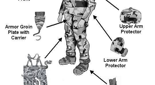
20 TM LOCATION AND DESCRIPTION OF MAJOR COMPONENTS The BASIC is made up of the following ballistic components: a. Helmet Cover (Ballistic) b. Face Shield c. Mine Protective Overboots d. Anti-Fragmentation Trousers (Ballistic) e. Vest Cover (Ballistic) f. Armor Chest Plate (Ballistic) g. Upper Arm Protector (Ballistic) h. Lower Arm Protector (Ballistic) i. Collar (Ballistic) j. Armor Groin Plate with Carrier (Ballistic)


21 TM Helmet Assembly Figure 1. Components of BASIC System
22 TM Foot Protection System (FPS) Spider Boots are available as an additional authorized item. Ankle Piece Lower Binding Upper Binding Leg Standard Pod Deflector Plate Figure 2. Foot Protection System. WARNING The operator must wear protective clothing in addition to the FPS. WARNING Use of FPS increases height of user. WARNING Use of FPS results in increased foot width. Must take care to take wider steps to avoid tripping or serious injury may result. WARNING Use of FPS Spider Boots may cause feet to slide more easily on flat ground
23 TM WARNING Use of FPS on uneven terrain may cause user to lose balance. User must walk with caution on these surfaces CAUTION Limit exposure of FPS to very wet environments. This will reduce the possibility of water seeping into the deflector. The FPS protects the operator by increasing the distance between the foot and a potential charge by 15 to 20 centimeters, by averting part of the charge away from the foot, and by absorbing some of the energy transferred from an anti-personnel mine. Sandpods are also available for use with the FPS. Figure 3. Sandpods
24 TM Table 1. Sizes. COMPONENT SIZES AVAILABLE Helmet Cover Small, Medium, Large Face Shield One size fits all Overboots 5,7,9,11,12 Trousers Small, Medium, Large Vest Cover Small, Medium, Large Armor Chest Plate One size fits all Upper Arm Protector Small, Medium, Large Lower Arm Protector Small, Medium, Large Collar Small, Medium, Large Armor Groin Plate One size fits all Groin Plate Carrier One size fits all FPS Spider Boot One size fits all END OF WORK PACKAGE

25 TM OPERATOR MAINTENANCE BODY ARMOR SET, INDIVIDUAL COUNTERMINE (BASIC) THEORY OF OPERATION This work package discusses theory of operation and protective qualities of the BASIC system. Armor plates are used to achieve the highest level of fragmentation protection for the chest and groin areas. Head area protection is achieved with a combined installation of the standard Personnel Armor System for Ground Troops (PASGT) helmet with a soft ballistic cover. The face shield does not provide the same level of protection provided by the helmet with cover. To provide optimal visual clarity, the face shield is constructed with a clear polycarbonate lens that provides reduced fragmentation protection. The neck, torso, arm and leg areas provide a range of ballistic protection through the use of multiple layers of ballistic materials, which form a strong yet pliable barrier against mine fragments. The feet are protected with component materials designed to deflect blast and fragments away from the feet. Figure 1. BASIC Fragmentation Protection Zones. END OF WORK PACKAGE /2 Blank
26
27 CHAPTER 2 OPERATOR INSTRUCTIONS FOR BODY ARMOR SET, INDIVIDUAL COUNTERMINE (BASIC)
28
 prior to donning the BASIC. Overboots 1.")
29 TM OPERATOR MAINTENANCE BODY ARMOR SET, INDIVIDUAL COUNTERMINE (BASIC) OPERATION UNDER USUAL CONDITIONS DONNING AND ADJUSTMENT This work package contains instructions for donning and adjusting the BASIC. Helmet Ensure helmet assembly is put together (see WP 0011) prior to donning the BASIC. Overboots 1. Be sure you have the correct size overboot for the type and size boot you are wearing, see WP Unfasten the buckles of the overboot and fully extend the tongue. 3. Place your boot into the overboot. Be sure your boot heel is seated at the back of the overboot for a secure fit. Figure 1. Donning the Overboot. 4. Fasten the overboot buckles and tighten the web straps until the overboot fits snugly over your boot

30 TM Figure 2. Fastening the Overboot Buckles. WARNING The overboot increases the height of your heel and sole. Use caution when walking to avoid tripping or twisting your ankle. 5. Walk around briefly then re-adjust the overboot, but do not get it uncomfortably tight. It may be necessary to re-adjust during use. END OF TASK NOTE It is recommended that the user adjust the FPS, take off the FPS, put on trousers, and then put the FPS back on. FPS Putting on the FPS 1. Orient the FPS so that the buckles, when fastened, are toward the outside of the foot
31 TM Figure 3. FPS Proper Orientation. 2. Position the ankle piece vertically and make sure the buckles are detached. 3. Place the foot on the platform. 4. Press down on the tongue and insert the grooved strap into the buckle. Figure 4. Fastening Buckle
32 TM Pull upwards on the outer buckle to tighten the strap. END OF TASK FPS Adjusting the Binding Figure 5. Tightening Strap. 1. Put on the military boots to be worn in conjunction with the FPS. The FPS can be adjusted for the thickness of the military boot and foot length. Thickness of Military Boot Adjustment Foot Length Adjustment Figure 6. Adjusting the FPS Binding. 2. Step onto the platform and position the foot so that the ball of the foot sits just in front of the binding
33 TM If the back of the military boot fits comfortably against the ankle support, no adjustment is necessary. If the fit is too tight or too loose, follow the rest of this procedure. 4. Remove the nylock nuts and bolts, which hold the upper binding and lower binding together. Nylock Nuts and Bolts Figure 7. Nylock Nuts and Bolts Removal. 5. Move the upper binding backward to accommodate a larger boot. Figure 8. Adjusting the Upper Binding
34 TM Move the boot forward to accommodate a smaller boot. Figure 9. Adjusting to Accommodate Smaller Boot. 7. Replace the bolts and tighten the nylock nuts when a comfortable fit has been obtained. END OF TASK Trousers NOTE Assistance may be needed to don and properly adjust the trousers. 1. Be sure you have the correct size trousers, see WP NOTE Trouser donning procedures are best performed while standing. 2. Hold the trousers in front of you with the inside facing you. NOTE A label located on the suspender strap points out the front end, which passes through the center front trouser loops

35 TM Fasten the suspenders so that they will crisscross at the back, and come straight down over the front of each shoulder to the trouser, by passing the ends through the loops on the top edge of the trousers and fastening the hook and loop fasteners. CENTER OPENING Figure 10. Fastening the Suspenders. 4. While holding the trousers in front of you with the inside facing you, pass your head through the center opening and pass your arms through the side openings of the suspenders. 5. Wrap the trousers around your waist and secure with the waist belt
36 TM NOTE Be sure pad is installed with the padded surface toward the shoulder for maximum comfort. 6. Install shoulder pads onto suspenders by, one at a time, unfastening each suspender, sliding the pad into position, and re-fastening the suspender. Figure 11. Installing Shoulder Pads Onto Suspender

37 TM Pull the elastic strap at the end of the groin protector back between the thighs and attach at the center back of the waist belt using the hook and pile fastener. NOTE Cross goes in the back. Fasten Fasten Fasten Fasten Fasten Fasten Figure 12. Trouser Adjustment
38 TM NOTE If trousers are adjusted too low, they will restrict your movements. 8. Adjust the height of the trousers so that the groin protector is placed firmly against the groin area, and where movement is not restricted. NOTE Trouser leg may be cuffed to adjust length before fastening the bottom leg strap. 9. Beginning at the top of your thigh, the assistant fastens the leg straps around the back of the trousers. Complete one leg before fastening the other. 10. Verify trouser length is just below the top edge of the overboot. 11. Walk briefly, then adjust the leg straps so that the trousers fit securely, but do not restrict movement. Additional adjustments may be needed during a mission. END OF TASK Vest Cover WARNING For maximum protection against antipersonnel mines, wear the vest cover with your PASGT Vest or Interceptor Body Armor. The BASIC must be worn with either the Interceptor Body Armor or the PASGT Vest. The vest cover will be worn over either the PASGT vest (with the collar up) or Interceptor Body Armor, Outer Tactical Vest (OTV). If wearing the OTV, assemble your OTV base vest without the collar, throat protector, groin protector, and small arms protective insert (SAPI) plates located in the front and back OTV pockets. The PASGT vest does not require dismantling
39 TM NOTE Assistance may be needed to don and properly adjust the vest cover. 1. Ensure you have the correct size vest cover, refer to WP 0009, and that you have a front and back vest cover half. The front half has a pocket on the outside that is closed by means of a flap with hook and pile fastener to place the chest plate, and a flap, low on the front where the groin plate is attached. The back half has an open pocket on the inside, approximately mid back; the pocket is for the storage of this manual. FRONT HALF BACK HALF Figure 13. Vest Cover. 2. Open the chest plate pocket on the front half at the bottom edge, and insert armor chest plate, with the curve to the front, into the pocket of the vest cover. Secure the chest plate by closing the flap at the bottom of the pocket with the hook and pile fastener

40 TM Figure 14. Inserting Armor Chest Plate. 3. Be sure the fragmentation protective insert is in the back half of the vest cover by opening the bottom edge of the vest cover back half. If not in place, or improperly placed, perform the following steps: a. Open vest cover back half at the bottom edge. b. Separate the protective insert from the vest cover. It is attached from both sides using hook and pile fasteners. NOTE Proper alignment is needed to allow the articulation of the insert and to prevent any folds in the material. c. Position protective insert so that it aligns with the hook and pile fasteners
41 TM WARNING Ensure that the fragmentation protective insert is not folded over inside the vest cover back half. Correct positioning is required to provide maximum available protection. Failure to do so may cause serious injury or death to personnel. d. Check for correct installation, then close the vest cover back half with the hook and pile fasteners. 4. Fasten the vest cover halves together at the shoulder tabs with the hook and pile fasteners. 5. Place your head through the center opening with the chest plate to the front. NOTE Correct position of the vest cover is to have the neckline of the cover at the bottom edge of the PASGT collar or OTV neckline. Vest is properly adjusted when the back half is against the PASGT collar or OTV neckline. 6. Adjust the hook and pile fasteners at each shoulder of the vest cover until the front neckline of the vest cover is at the bottom edge of the PASGT collar or OTV neckline and the back vest cover is against the PASGT collar or OTV neckline. 7. Wrap the narrow elastic band that is attached to the edges of the vest cover back half, around the mid section and under the front half of the vest cover
42 TM Narrow Band Figure 15. Vest Cover Narrow Elastic Band. NOTE Assistance may be required to align the tabs. 8. Fasten the tabs at the sides of the vest cover front half, to the back half using the hook and pile fasteners. 9. Wrap the wide elastic band that is attached to the outside of the vest cover back half over the front of the vest cover front half and secure using the hook and pile fasteners. Figure 16. Donning the Vest Cover. END OF TASK

43 TM Armor Groin Plate The armor groin plate attaches to the outside of the vest cover, below the chest plate. The groin plate is a one size fits all item. NOTE The back of the cloth carrier has two snaps, be sure the outwardly curved section of the groin plate is opposite the snaps. 1. Insert the groin plate into the cloth carrier and close using the hook and pile fasteners. Figure 17. Groin Plate. NOTE There are two rows of snap and pile combinations, an upper and lower position. Position the plate so that it is not too low to impede movement

44 TM Lift the flap on the front of the vest cover and attach the groin plate by means of the hook and pile fasteners and snaps to one of the rows. Be sure the snaps from the cloth carrier to the vest cover are secured to prevent the plate coming loose during operations. 3. Close the vest cover flap over the groin plate using the hook and pile fasteners. Figure 18. Attaching Groin Plate to Vest Cover. 4. Pull the elastic strap that is attached to the bottom of the groin plate carrier back between your legs and attach to the outside of the back vest cover half using the hook and pile fastener. Adjust the slack in the strap so the groin plate does not impede movement
.")
45 TM Figure 19. Rear View of BASIC (Without Arm Protection). END OF TASK


46 TM Arm Protectors The arm protectors are in two pieces, an upper and lower section. Assistance is needed to properly don the arm protectors. LOWER UPPER Figure 20. Upper and Lower Arm Protectors. 1. Be sure you have the correct size arm protectors, see WP Begin with either the right or left set of arm protectors. 3. Connect the lower arm protector to the upper arm protector by passing the strap from the lower arm through the loop at the bottom edge of the upper arm protector and fasten with the hook and loop fastener. Figure 21. Upper and Lower Arm Protectors Connected

47 TM Disconnect the buckle of the strap at the shoulder of the protective vest cover, and loosen the adjustment of the buckle 5. Pass the strap from the vest cover, through the upper loop of the upper arm protector and fasten the buckle. NOTE If upper protector is positioned below elbow crease it will restrict movement. Figure 22. Attaching Arm Protectors to Vest
48 TM Adjust the position of upper arm protector, so that the bottom edge of the upper arm protector is just above the crease of the elbow with the arm bent to approximately 90 degrees. 90 O Figure 23. Adjusting Position of Upper Arm Protector. 7. Fasten the upper protector around the upper arm using the strap and fasten with the hook and loop fastener. NOTE If lower protector is positioned below wrist crease, it will restrict movement

49 TM Loosen the strap that attaches the lower to upper arm protector if necessary to make position adjustments. With the arm bent to approximately 90 degrees, and palm up, position the lower arm protector under the forearm, with the straight edge positioned just above the wrist crease. 9. Fasten the lower protector using the two elastic bands and fasten with the hook and pile fasteners. Reposition the arm protector if necessary. 10. Wrap the ballistic material of the lower arm protector around the forearm and secure using the elastic band with the wide tab and the hook and pile fastener. END OF TASK Figure 24. Securing Lower Arm Protection. Collar The BASIC System collar is worn around the neck over the PASGT or OTV neckline. 1. Ensure you have the correct size collar. See WP Wrap the collar around the neck so that the hook and pile fasten is on the right side of the neck

50 TM Figure 25. BASIC Collar. 3. Fasten the collar using the hook and pile fastener. 4. Position the collar so that it covers the neck to just below the ears, but allows free movement of the neck and chin. END OF TASK Helmet WARNING Ballistic cover and face shield add weight to the helmet. The assembly shifts the balance point forward. A high risk of injury to the neck may be expected when the soldier wearing the helmet, helmet cover, and face shield is subjected to external forces or accelerations such as falls, jumping from heights, vehicular movement over rough terrain, or direct impact to the helmet. Don helmet assembly and secure with the PASGT chinstrap. The face shield is raised and lowered by pressing the ribbed section of the release hinge, and moving the face shield to the desired position. END OF TASK END OF WORK PACKAGE
51 TM OPEARTOR MAINTENANCE BODY ARMOR SET, INDIVIDUAL COUNTERMINE (BASIC) OPERATION UNDER USUAL CONDITIONS DOFFING INSTRUCTIONS This work package contains information about doffing the BASIC. CAUTION Hook and pile fasteners should be reclosed after items are removed to prevent damage to fasteners. NOTE Assistance may be required to remove the BASIC. 1. Close hook and pile fasteners after each item is removed. 2. Remove the PASGT helmet with helmet cover and face shield assembly. 3. Remove collar. 4. Remove lower and upper arm protectors. 5. Remove armor groin plate with carrier. 6. Remove vest cover and PASGT (or OTV) vest. 7. Remove trousers, leaving the suspenders attached. 8. Remove overboots. END OF WORK PACKAGE /2 Blank
52
53 TM OPERATOR MAINTENACE BODY ARMOR SET, INDIVIDUAL COUNTERMINE (BASIC) OPERATION UNDER USUAL CONDITIONS LOCATION AND CONTENTS OF DATA PLATES/ DECALS/ LABELS This work package contains information about the location and contents of the data plates, decals, and labels found on the BASIC. Figure 1. Typical Label
54 TM Figure 2. Typical Label


55 TM Figure 3. Location of Typical Labels on Helmet Cover. Figure 4. Location of Typical Labels on Collar

56 TM Figure 5. Location of Typical Labels on Inside Vest Cover Front Half

57 TM Figure 6. Location of Typical Labels on Vest Cover Back Half


58 TM Figure 7. Location of Typical Labels on Upper Arm Protector. Figure 8. Location of Typical Labels on Lower Arm Protector
59 TM Figure 9. Location of Typical Labels on Groin Plate Carrier

60 TM Figure 10. Groin Plate Labels. Figure 11. Chest Plate Labels. END OF WORK PACKAGE
61 TM OPERATOR MAINTENANCE BODY ARMOR SET, INDIVIDUAL COUNTERMINE (BASIC) OPERATION UNDER UNUSUAL CONDITIONS Cold Weather Conditions (FM ) The BASIC may be worn over the Extended Cold Weather Clothing System (ECWCS) when conditions warrant protection from a cold environment. The BASIC is donned over the ECWCS, which may require the use of larger BASIC component sizes than under normal conditions. Also the protective overboot will not fit over the Extreme Weather overboot. Use the Intermediate Cold/Wet boot (see Table 3, WP 0009). Cold conditions add the risk of cold injuries such as hypothermia, chilblain, trench foot, frostnip, and frostbite. Seek medical attention if any of these conditions occur. When the BASIC is stored under cold conditions, it will act as a heat sink and draw body heat from the user. Additionally, the extra layers may trap moisture close to the body increasing the likelihood of cold related injuries. Cold Stress Prevention 1. Be able to recognize cold weather stress and injuries. 2. When using cold weather gear, keep it clean, wear it in loose layers, and stay dry. 3. Avoid overheating, perspiration will cause loss of insulation value, and the body will cool quicker. 4. If the BASIC has been stored in a cold area, warm it prior to use to prevent a cold-soak/loss of body heat condition. 5. Drink plenty of water. Dehydration reduces work capacity, appetite, and alertness, which can lead to cold stress injuries. 6. Work using the buddy system. Check each other for signs of cold injury. 7. Rotate periods of work based on cold exposure
62 Hot Weather Conditions (FM ) TM Hot conditions add the threat of heat related illness. These include heat cramps, heat rash, heat exhaustion and heat stroke. All of these conditions require medical attention, and heat exhaustion and heat stroke require immediate medical attention. Table 1 contains the recommended work and rest times and recommended water intake. Reduce the risk of heat related illness by: 1. Increase water intake. Intake should be 1 to 1.5 quarts per hour while working, up to 12 quarts per day. 2. Replace salt loss by eating all meals. 3. Rotate periods of work based on heat exposure. 4. When possible work during coolest part of the day
63 TM Table 1. Temperature Specifications/ Recommended Work Schedules/Rest Periods/Water Intake. Temperature ( F) Relative Humidity Water Intake per Hour (qt.)* Hourly Work/Rest Schedule Minutes Maximum Work Time in 24 Hour Cycle Minutes 77 Low-High ¾ 40/ Low- Moderate ( 74.5%) ¾ 40/ High (>75%) 1 30/ Low-High 1 30/ Low- 1 30/ Moderate ( 74.5%) High 1 20/40 80 (>75%) Low-High 1 20/ Low ( 50%) 1 20/ Moderate /50 40 High (>50.5%) >110 Low-High 1.5 NFW** NFW** * Individual requirements will vary by ± 0.25 qt. ** (NFW) No Further Work. Stop Mine Clearing Operations and Remove BASIC
64 TM Nuclear, Biological and Chemical (NBC) Environment The BASIC is donned over the MOPP gear, which may require the use of larger sizes than under normal conditions. Don all components of MOPP gear except for the protective boots. Remove face shield from helmet assembly (WP 0012) since the NBC protective mask interferes with the face shield. WARNING Use of the BASIC with MOPP gear increases the possibility of heat illness. Don BASIC. See WP Don BASIC and Suit, Contamination Avoidance, Liquid Protection (SCALPS) over your overboots. The BASIC P3I can be decontaminated for disposal purposes only and is not to be reused. If exposed to CB agents MOPP IV posture must be maintained until BASIC P3I has been safely disposed (FM 3-5, NBC Decontamination). Water Conditions Working near water, especially near deep water poses additional risk due to the weight of the BASIC. If immersed in deep water, follow these procedures: 1. Remove and discard helmet assembly. 2. If shore, boat, or other means of safety is close (a few feet) swim to the safe location. 3. If step 2 is not possible, drop the chest and groin plate. Remove overboots. Remove the remainder of the BASIC, and form the components into a ball and utilize the flotation available from these components. END OF WORK PACKAGE
65 TM OPERATOR MAINTENANCE BODY ARMOR SET, INDIVIDUAL COUNTERMINE (BASIC) OPERATION UNDER UNUSUAL CONDITIONS INSTALLATION AND USE OF FPS SANDPODS The sandpods for the FPS are molded plastic discs, which can be positioned between the legs and the standard rubber pods of the FPS to allow the operator to work with greater ease in sandy conditions. The sandpods distribute weight placed on the legs over a greater area and help to prevent the FPS from sinking into sandy terrain. Figure 1. FPS Sandpods. 1. Unscrew the standard pod and position the sandpod so that the notch on the underside of the leg fits through the oblong slit in the disc. Standard Pod Oblong Slit Figure 2. Removing Standard Pod
66 TM Replace the standard pod. When the pod is correctly positioned and tightened, the knob should sit in the notch on the underside of the pod. Turn the pod until you the knob fall into place. Always install all four pods. Knob Underside of Pod Figure 3. Installing FPS Sandpod. END OF TASK END OF WORK PACKAGE
67 CHAPTER 3 OPERATOR MAINTENANCE INSTRUCTIONS FOR BODY ARMOR SET, INDIVIDUAL COUNTERMINE (BASIC)
68
69 TM OPERATOR MAINTENANCE BODY ARMOR SET, INDIVIDUAL COUNTERMINE (BASIC) EQUIPMENT/USER FITTING INSTRUCTIONS INITIAL SETUP: Tools/Special Tools Measuring Tape Personnel Required One Five sizing procedures are required for the proper fit of the system. However the Face Shield, Armor Chest Plate, and Armor Groin Plate are one size fits all, and require no sizing procedure. If the predicted size fits poorly, determining the best fitting size by trying an alternate size. Helmet Cover The helmet cover for the PASGT helmet comes in three sizes. Refer to table 1 for the recommended helmet cover size. Table 1. Helmet Sizing Information. PSAGT Helmet Size X-Small and Small Medium Large and X-Large BASIC Helmet Cover Small Medium Large Protective Overboots Over Standard Combat Boot The overboots come in five sizes and are intended to be worn over standard issue combat boots. Some half-sizes and wider widths of combat boots will achieve a better fit by using the larger than specified overboot. If you are unable to buckle the straps of the overboot, select the next larger overboot for use during the mission. If your combat boot heel lifts while walking in the overboot, select the next smaller size overboot. Refer to table 2 for the recommended overboot size
70 TM Table 2. Sizing Information for Protective Overboot Over Combat Boots. Combat Boot Size Protective Overboot Style Protective Overboot Over Intermediate Cold/Wet Boots (ICWB) Due to the thick ICWB sole, the BASIC overboot only fits over an ICWB boot that is one size smaller. Refer to table 3 for the recommended overboot size. Table 3. Sizing Information for Protective Overboot Over ICWB. ICWB Size Protective Overboot Style
71 TM WARNING Be sure to evaluate the fit of overboots when worn with alternate military footwear before beginning a mission. Failure to ensure correct size is worn may result in injury to personnel. The protective overboot may be worn over other standard military footwear when proper fit can be obtained. There are certain types of footwear that the protective overboot cannot be worn over, such as the vapor barrier boot. Be sure that the overboot fits properly before conducting a mission. FPS Spider Boots Spider Boots are one size fits all. Refer to WP 0004 for Donning and Adjustment, and for binding adjustment instructions. Vest Cover and Collar The BASIC vest cover and collar are available in three sizes and are intended to be worn over the basic PASGT vest or the OTV. The collar comes with the vest cover in the same sizes, but may be mixed with other sizes to achieve the best fit. The users chest circumference is measured at the fullest part of the chest. Refer to Table 4 for the recommended vest cover and collar size. Figure 1. Measuring/Sizing for Vest Cover and Collar
 Vest Cover/Collar Size Less than 36 Small 36 42 Medium Greater than 42 Large Upper and Lower Arm Protectors BASIC upper and lower arm protectors come in three sizes.")
72 TM Table 4. Sizing Information for Vest Cover and Collar. Chest Circumference (Inches) Vest Cover/Collar Size Less than 36 Small Medium Greater than 42 Large Upper and Lower Arm Protectors BASIC upper and lower arm protectors come in three sizes. They are intended to be worn over the sleeves of Battle Dress Uniforms (BDU) or over exposed arms when short sleeve garments are worn. A long sleeve garment should be worn to minimize the chafing of the skin on the arms. Predicted sizes from the outseam measurement will be the same for both the upper and lower protectors, however, upper and lower protectors of different sizes may be mixed to achieve a better fit. Sleeve outseam is measured from the top of the shoulder joint, to the wrist using a tape measure. Ensure the arms are hanging to the side and slightly bent when obtaining the measurement. Refer to Table 5 for the recommended arm protector size. Figure 2. Measuring/Sizing for Upper and Lower Arm Protectors
 Arm Protector Size Less than 22 Small 22 24 Medium Greater than 24 Large Anti-Fragmentation Trouser The BASIC Anti-Fragmentation Trouser comes in three sizes.")
73 TM Table 5. Sizing Information for Upper and Lower Arm Protector. Sleeve Outseam (Inches) Arm Protector Size Less than 22 Small Medium Greater than 24 Large Anti-Fragmentation Trouser The BASIC Anti-Fragmentation Trouser comes in three sizes. The Trouser is intended to be worn over BDUs. The Trouser inseam is derived from measuring from the crotch to the ground (or floor) and subtracting 2 inches to derive the inseam measurement. Refer to Table 6 for the recommended trouser size. Figure 3. Measuring/Sizing for Anti-Fragmentation Trousers
74 TM Table 6. Sizing Information for Anti-Fragmentation Trousers. Inseam (Inches) Trouser Size Less than 30 Small Medium Greater than 32 Large END OF WORK PACKAGE
75 TM OPERATOR MAINTENANCE BODY ARMOR SET, INDIVIDUAL COUNTERMINE (BASIC) PREVENTIVE MAINTENANCE CHECKS AND SERVICES (PMCS) INTRODUCTION General Preventive maintenance checks and services (PMCS) are performed to keep the BASIC in operating condition. The checks are used to find, correct, or report problems. Operator is to do the PMCS jobs as shown in the PMCS table. PMCS is to be done before, during and after use of the BASIC. Before you use the BASIC, do the PMCS. During use of BASIC periodically perform PMCS. After you have used the BASIC, perform PMCS. PMCS COLUMN DESCRIPTION ITEM The order the PMCS should be performed and a reference number for maintenance forms. INTERVAL Tells when the check should be performed. ITEM TO BE CHECKED OR SERVICED Tells which item to perform the PMCS procedure on. PROCEDURE Tells the procedure to perform. If item cannot be repaired, it must be replaced. EQUIPMENT NOT READY IF: Tells what conditions render the BASIC unfit to perform the mission
76 TM Table 1. Preventive Maintenance Checks and Services. ITEM NO. INTERVAL ITEM TO BE CHECKED OR SERVICED 1 Before Vest Cover, Trousers, Collar, Overboots, Groin Plate Carrier 2 Before Hook and Pile Fasteners PROCEDURE Check for: Tears, cuts, or snags and soiling. For tears less than 1 inch refer to WP 0014 for repair procedures. If tears are over 1 inch, refer to higher-level maintenance for repair. Soiling refer to WP 0013 for cleaning procedures. Exposure of yellow filler. Lumping or bunching of ballistic materials. Inspect hook and pile fasteners for tearing or damage. Refer damaged hook and pile fasteners to higher-level maintenance for repair. EQUIPMENT NOT READY IF: Cuts or tears are greater than 1 inch in size. Gray or dirty areas on ballistic filler that may conceal cuts or tears. Filler is exposed When lumping and/or bunching cannot be flattened or removed by smoothing by hand. Fasteners are damaged such that they will not fasten securely causing improper fit
77 TM Table 1. Preventive Maintenance Checks and Services - cont. ITEM NO. INTERVAL ITEM TO BE CHECKED OR SERVICED 3 Before Straps/ Elastic Webbing PROCEDURE Inspect straps and elastic webbing for damage. If damaged, refer to higher-level maintenance for repair. EQUIPMENT NOT READY IF: Straps or webbing are damaged and will not function properly causing improper fit. 4 Before Face Shield Inspect for cracks and scratches. Face shield is cracked or scratched such that it is difficult to see clearly through it. 5 Before Ballistic Plates Shake the plate to see if it rattles. Check for individual chips on the black surface coating. Check for cracks. Plate rattles. Chips are greater than 1 inch in diameter. Cracks are greater than 1 inch long or 1/16 inch wide in the inner ballistic material (white)
78 TM Table 1. Preventive Maintenance Checks and Services cont. ITEM NO. INTERVAL ITEM TO BE CHECKED OR SERVICED 6 During Fasteners/ Straps PROCEDURE Inspect for secure fit and proper function of straps/ Fasteners, as well as damage. EQUIPMENT NOT READY IF: Straps or fasteners are damaged such that secure and proper fit cannot be maintained 7 After BASIC Inspect for explosive fragment hits. Fragments are embedded in the ballistic filler (yellow material) or tears, cuts, or soiling from fragment hits are found. 8 After Vest Cover, Trousers, Collar, Overboots, Groin Plate Carrier Check for tears, cuts, or snags. Refer any torn, cut, or snagged items to higher-level maintenance for repair. Tears, cuts, or snags are found
79 TM Table 1. Preventive Maintenance Checks and Services cont. ITEM NO. INTERVAL ITEM TO BE CHECKED OR SERVICED 9 After FPS Spider Boots END OF WORK PACKAGE PROCEDURE Check the binding mechanisms to ensure that they are free from dirt and debris. Check under the hinge plate to ensure the area is free from dirt and debris. Check for worn or damaged pods. Replace a pod when any of the knobs has been completely worn down. EQUIPMENT NOT READY IF: Straps of fasteners are damaged such that secure and proper fit cannot be maintained. Knob is completely worn /6 Blank
80

81 TM OPERATOR MAINTENANCE BODY ARMOR SET, INDIVIDUAL COUNTERMINE (BASIC) HELMET ASSEMBLY INITIAL SETUP: Tools/Special Tools None Materials Required None Personnel Required One References WP 0009 Helmet assembly includes installation of the BASIC helmet cover and face shield. Helmet Cover The BASIC Helmet Cover is installed over the PASGT helmet and is assembled first, before donning the rest of the BASIC system to avoid heat stress. Don the assembled helmet only after you have donned the rest of the BASIC. 1. Open all eight fastening tabs. NOTE Ensure you have the correct size cover (see WP 0009). Figure 1. BASIC Helmet Cover

82 TM Remove and stow standard camouflage cover (not the ballistic helmet cover) from helmet. 3. Slide the helmet into the ballistic cover, starting from the back of the helmet, and pull cover around the brim. Adjust the helmet cover until it overlaps the edge of the PASGT helmet evenly around the brim. Backside of PASGT Helmet Figure 2. Sliding the Helmet Into the Ballistic Cover. Helmet Cover 4. Unsnap the chinstrap from the PASGT helmet. Pass the ends of the chinstrap through the buttonholes of the helmet cover

83 TM Figure 3. Passing the Ends of Chinstrap through the Buttonholes. NOTE Do not fasten the back 2 center tabs. 5. Loop each fastening tab of the helmet cover around the PASGT helmet s fixed web suspension, located behind the headband except for the two back center tabs


84 TM NOTE Figure 4 details installing the PASGT helmet cover over the standard PASGT helmet cloth cover. Headband Figure 4. Helmet Assembly. END OF TASK Face Shield The BASIC Face shield is installed over the PASGT helmet and BASIC Helmet Cover. Assemble the shield to the helmet before donning the rest of the BASIC system to avoid heat stress. Don the assembled helmet with shield only after you have donned the rest of the BASIC. 1. Loosen the black web strap as much as possible while keeping the strap through the buckle. 2. Center the J hooks on the strap, opposite of the shield, approximately two inches apart. 3. In a sitting position, place the PASGT helmet with cover on your legs, with the inside up and the front away from you
, hook the black plastic gutter over the front lip of the helmet, then position the web strap around the helmet, with the")
85 TM Figure 5. Helmet Assembly continued. 4. With the face shield assembly upside down and in the deployed position (down), hook the black plastic gutter over the front lip of the helmet, then position the web strap around the helmet, with the adjusting buckle all the way to one side. See Figure 5, above. 5. Pass the two J hooks through the buttonholes at the back center of the helmet cover and hook them over the edge of the PASGT helmet

86 TM NOTE Figure 6 details J hooks. The PASGT helmet is shown up side down showing the J hooks through the buttonholes at the center of the helmet. Figure 6. Helmet Assembly continued. 6. Pass the back center tabs behind the helmet web strap suspension and attach the strap's hook fastener to the pile fastener on the ballistic cover. 7. Work the strap from the side opposite the buckle through the J hooks so that it is snug and lays flat. 8. Tighten the strap at the buckle while making sure the black plastic gutter remains centered on the front of the PASGT helmet and the seal lies smoothly with no folds of material bunched underneath. END OF TASK END OF WORK PACKAGE
87 TM OPERATOR MAINTENANCE BODY ARMOR SET, INDIVIDUAL COUNTERMINE (BASIC) FACE SHIELD DISASSEMBLY PROCEDURE INITIAL SETUP: Tools/Special Tools None Personnel Required One Removal of Face Shield 1. Loosen strap. 2. Unfasten the two helmet cover tabs at the back of the PASGT helmet. 3. Unhook shield hooks from helmet and pass them through the helmet cover. 4. Unhook front of face shield from the helmet and remove the shield. END OF TASK Remove Helmet Cover 1. Unfasten helmet cover tabs from around the helmet fixed web suspension. 2. Remove helmet cover from the PASGT helmet. END OF TASK END OF WORK PACKAGE /2 Blank
88
89 TM OPERATOR MAINTENANCE BODY ARMOR SET, INDIVIDUAL COUNTERMINE (BASIC) CLEANING INSTRUCTIONS INITIAL SETUP: Tools/Special Tools None Materials Required Brush, Soft Bristle (items 2-4, WP 0023) Cloth, Cleaning (item 1, WP 0023) Detergent, Mild (items 6-7, WP 0023) Measuring Tape (item 10, WP 0023) Rag (item 5, WP 0023) Soap, Mild (item 9, WP 0023) Solvent, Dry Cleaning (item 8, WP 0023) Personnel Required One References None 1. The BASIC items listed below may be cleaned using the following instructions. Helmet Cover Trousers Front and Rear Vest Cover Halves Cloth Carrier for Groin Plate Upper and Lower arm protectors Collar a. Remove Ballistic inserts from front and back vest cover halves and the cloth carrier for the groin plate. b. Remove as much dirt/mud/dust from BASIC material as possible using a brush
90 TM CAUTION Do not use chlorine bleach, yellow soap, cleaning fluids or solvents. Do not launder or dry components of the BASIC in commercial or home type laundry equipment. c. Hand wash in warm water using mild soap or mild detergent. CAUTION Do Not dry in direct sunlight, direct heat, or near an open flame. d. Dry item in shade or indoors. 2. Chest Plate and Groin Plate CAUTION Never use a stiff bristle or wire brush. a. Remove loose dirt and lint from outer surface using a clean cloth or soft bristle brush. CAUTION Do not submerge armor plates in water. b. Heavy grease or oil stains may be pre-spotted with dry cleaning solvent and mild detergent and scrubbed with a soft brush
91 TM c. If needed, plates may be cleaned using a rag or brush dipped in a solution of mild detergent. d. Wipe armor plate(s) with damp cloths until all soap or solvent is removed. CAUTION Do not dry in direct sunlight, direct heat, or near an open flame. e. Wipe plate(s) with dry cloth and allow to air dry. 3. Face Shield. CAUTION Washing face shield without first rinsing may scratch surface. Do not use ammonia, alkaline cleaners, abrasive compounds or solvents. a. Rinse off any dirt/mud/dust for face shield using clean warm water. b. Hand wash item using soft cloth and mild soap or mild detergent solution. c. Rinse with clean warm water until all soap or detergent is removed
92 TM CAUTION Do not rub the polycarbonate face shield. Doing so may scratch the surface. d. Pat the polycarbonate shield with a dry soft cloth to pick up excess moisture, then allow to air dry. 4. Overboots. a. Brush off excess dirt with a soft brush. b. Wash overboot with warm water. 5. Air-dry overboot. CAUTION Do Not dry in direct sunlight, direct heat, or near an open flame. END OF TASK END OF WORK PACKAGE
93 TM OPERATOR MAINTENANCE BODY ARMOR SET, INDIVIDUAL COUNTERMINE (BASIC) GENERAL REPAIR INSTRUCTIONS For repairs not contained herein, turn in for repair. Tears or cuts less than one inch may be temporarily repaired using tape, item 10, WP Tape should extend at least 1/2 inch beyond the ends of the tear or cut. The suit will be referred to higher maintenance after the mission is completed. END OF TASK END OF WORK PACKAGE /2 Blank
94
95 TM OPERATOR MAINTENANCE BODY ARMOR SET, INDIVIDUAL COUNTERMINE (BASIC) REPLACING DAMAGED (FPS) PODS This work package provides instructions for replacing damaged pods on the FPS Spider Boot. Figure 1. Changing Damaged Pod. 1. Unscrew the worn or damaged pod. 2. Remove the pod. 3. Push the replacement pod onto the leg. 4. Screw the pod onto the leg until completely secure. 5. Make sure the knob on the underside of the leg sits in the groove carved into top of the pod. END OF TASK END OF WORK PACKAGE /2 Blank
96
97 TM OPERATOR MAINTENANCE BODY ARMOR SET, INDIVIDUAL COUNTERMINE (BASIC) RE-ASSEMBLY OF FPS This work package provides information to assist in properly re-assembling the FPS following component replacement. Attaching the Legs to the Deflector Plate 1. Insert a 1.25-inch screw through the deflector plate and one leg assembly, with the head facing up. 2. Place a flat washer on the screw on the bottom side of the leg and tighten a nylon locknut onto the screw. 3. Put a vinyl cap over the end of the screw. Repeat for the other screws in that leg and again for the other leg inch Screw Flat Washer Deflector Plate Nylon Locknut Vinyl Cap END OF TASK Figure 1. Attaching the Legs to the Deflector Plate
98 Replacing the T-Nuts in the Hinge Plate TM Fold the hinge plate out so that you can see the bottom of the T-nuts. 2. Pry the T-nut out of the bottom of the hinge plate with a flatblade screwdriver. 3. Press a new T-nut into the hole in the hinge plate, being sure that the flush side is facing the right way. T-Nuts END OF TASK Figure 2. Replacing the T-Nuts in the Hinge Plate. Securing the Hinge Plate 1. Insert a 1-inch screw through the hinge plate with the head facing up. 2. Place a flat washer on the screw on the bottom of the hinge plate and tighten a nylon locknut onto the screw. Repeat for the other screws in the hinge plate
99 TM Hinge Plate 1-inch Screw Flat Washer Figure 3. Securing the Hinge Plate. END OF TASK Attaching the Legs and Deflector to the Hinge Plate 1. Insert two 2.5-inch screws up through the hinge plate using the two holes near the screws holding the hinge plate on. 2. Add a nylon spacer to the end of the screws. 3. Insert two 2.25-inch screws up through the other two holes in the hinge plate and add nylon spacers to those screws. Figure 4. Attaching the Binding to the Hinge Plate
100 TM Turn the leg/deflector plate assembly upside-down (legs facing up and insert the assembly onto the four screws facing up out of the hinge plate. 5. Turn the leg/deflector assembly upside-down (legs facing up) and insert the assembly onto the four screws facing up out of the hinge plate. Figure 5. Inserting the Leg/Deflector Assembly Onto Hinge Plate. 6. Place a flat washer on each screw and tighten a nylon locknut onto each screw. Attach a vinyl cap to each of the screw ends
101 TM Figure 6. Placing Flat Washer and Attaching Vinyl Cap. 7. Place the binding on the hinge plate. Line up the holes in the binding with the T nuts in the hinge plates. Figure 7. Attaching the Binding to the Hinge Plate. END OF TASK END OF WORK PACKAGE /6 Blank
102
103 TM OPERATOR MAINTENANCE BODY ARMOR SET, INDIVIDUAL COUNTERMINE (BASIC) PREPARATION FOR STORAGE INITIAL SETUP: Materials Required Cloth (item 1, WP 0023) Sheet, plastic (item 11, WP 0023) Clean all components (WP 0013) and secure all closures before storing. CAUTION Minimize folding or bunching of ballistic components. Repeated folding in the same location can increase the potential of abrading the ballistic components thus decreasing the item s service life. The BASIC may be stored in a bag/container or Air Force Bag (refer to WP 0024). The following steps provide folding instructions and suggested packing of the Air Force bag. Figure 1. Carry Bag for BASIC Components

104 TM Folding Instructions: Trousers Layer 1 1. Fold lengthwise along crotch seam. Figure 2. Folding Trousers. 2. Then fold crosswise along knee. 3. Place in bottom of storage bag, or container. END OF TASK Armor Groin Plate Layer 2 1. Place armor groin plate in carrier and secure closure. NOTE Closing hook and loop fasteners will eliminate snagging other materials
105 TM Engage groin plate carrier elastic webbing, hook-fastening tape to groin carrier loop fastening tape. Front View Rear View Figure 3. Groin Plate. 3. Place armor groin plate in carrier on folded trouser END OF TASK Vest Cover and Armor Chest Plate Layer 3 1. Place armor chest plate in pocket and secure closure. 2. Check that all other vest cover closures are secure. 3. Lay vest cover with armor plate flat or with slightly rolled lengthwise edges on top of the groin plate. 4. Disconnect upper arm protectors from lower arm protectors. NOTE The ballistic inserts will cushion and protect the face shield visor
106 TM Place (insert) face shield visor section between left and right upper arm protectors and place into one end of bag. 6. Place upper arm protectors and face shield, next to the PASGT helmet. 7. Place lower arm protectors (slightly rolled from engaged closures), helmet cover (folds naturally along lengthwise of center crown), and collar (folds naturally lengthwise along center front and back) on top of the upper arm protectors and face shield. NOTE Positioning the overboots sole-tosole will assist in concentrating any attached dirt and debris to one area 8. Position overboots to have sole-to-sole contact. Place overboots beside the upper arm protectors. 9. Close the bag. 10. If not using Air Force bag, cover components with cloth or plastic sheet. END OF TASK END OF WORK PACKAGE
107 TM OPERATOR MAINTENANCE BODY ARMOR SET, INDIVIDUAL COUNTERMINE (BASIC) PREPARATION FOR FPS STORAGE AND TRANSPORT This work package provides instructions for preparing FPS for storage and movement. 1. Fold down the ankle pieces. 2. Attach the straps over the ankle pieces to keep them in place. Ankle Pieces Figure 1. Ankle Pieces (Folded Down). 3. Position the boots so that the legs interlock in a compact configuration. Figure 2. FPS Compact Configuration
108 TM Place the interlocking boots on the carry strap. Figure 3. Interlocking Boots with Travel Strap. 5. Wrap the carry strap loops around the legs and fasten the buckles. Figure 4. Carry Strap Wrapped Around FPS. 6. Store the FPS in a dry location. END OF TASK
109 TM Using the Carry Strap for Storage and Movement 1. Fold down the ankle supports. 2. Attach the straps over the ankle pieces to keep them in place 3. Position the boots so that the legs interlock in a compact configuration. 4. Wrap the carry strap loops around the legs and fasten the buckles. 5. Store the FPS in a dry location. Figure 5. Using the Carry Strap for Storage and Movement. END OF TASK END OF WORK PACKAGE /4 Blank
110
111 CHAPTER 4 SUPPORTING INFORMATION FOR BODY ARMOR SET, INDIVIDUAL COUNTERMINE (BASIC)
112
113 TM OPERATOR MAINTENANCE BODY ARMOR SET, INDIVIDUAL COUNTERMINE (BASIC) REFERENCES This work package lists all field manuals, forms, technical manuals, and miscellaneous publications referenced in this manual. FIELD MANUALS FM FM 3-5 FM FORMS DA Form 2028 SF 368 TECHNICAL MANUALS TM MISCELLANEOUS PUBS DA PAM MIL-B MIL-B MIL-O Mine/Countermine Operations NBC Decontamination First Aid for Soldiers Recommended changes to Publications and Blank Forms Product Quality Deficiency Report Unit and Direct Support Maintenance Manual for General Repair Procedures for Individual Equipment Functional User's Manual for the Army Maintenance Management System (TAMMS) Boots, Cold Weather, Insulated, Rubber (Wet-Cold: Dry-Extreme Cold) Boots, Intermediate Cold/Wet Overshoes, Men's and Women's, Boot, Combat END OF WORK PACKAGE /2 Blank
114
115 TM OPERATOR MAINTENANCE BODY ARMOR SET, INDIVIDUAL COUNTERMINE (BASIC) COMPONENTS OF END ITEM AND BASIC ISSUE ITEMS LISTS INTRODUCTION Scope This work package lists COEI and BII for the Body Armor Set, Individual Countermine (BASIC) to help you inventory items for safe and efficient operation of the equipment. General The COEI and BII information is divided into the following lists: Components of End Item (COEI). This list is for information purposes only and is not authority to requisition replacements. These items are part of the Body Armor Set, Individual Countermine (BASIC). As part of the end item, these items must be with the end item whenever it is issued or transferred between property accounts. Items of COEI are removed and separately packaged for transportation or shipment only when necessary. Illustrations are furnished to help you find and identify the items. Basic Issue Items (BII). There are no Basic Issue Items for the Body Armor Set, Individual Countermine (BASIC). Explanation of Columns in the COEI List Column (1) National Stock Number (NSN). Identifies the stock number of the item to be used for requisitioning purposes. Column (2) Description, CAGEC, and Part Number. Identifies the Federal item name (in all capital letters) followed by a minimum description when needed. The stowage location of COEI and BII is also included in this column. The last line below the description is the CAGEC (commercial and Government entity code) (in parentheses) and the part number. Column (3) Unit of Issue (U/I). Indicates the count of the item as issued per the National Stock Number shown in column (2). Column (4) Qty Rqr. Indicates the quantity required
 ILLUS NUMBER (2) NATIONAL STOCK NUMBER (NSN) (3) DESCRIPTION, PART NUMBER/ (CAGEC) (4) USABLE ON CODE (5) U/I (6) QTY RQR 1 8470-01-472-1904 Small Helmet Cover, Ballistic 4P613, CY00-002 SMALL 1")
116 TM Table 1. Components of End Item List. (1) ILLUS NUMBER (2) NATIONAL STOCK NUMBER (NSN) (3) DESCRIPTION, PART NUMBER/ (CAGEC) (4) USABLE ON CODE (5) U/I (6) QTY RQR Small Helmet Cover, Ballistic 4P613, CY SMALL Medium Helmet Cover, Ballistic 4P613, CY MEDIUM Large Helmet Cover, Ballistic 4P613, CY LARGE EA 1 EA 1 EA
 ILLUS NUMBER (2) NATIONAL STOCK NUMBER (NSN) (3) DESCRIPTION, PART NUMBER/ (CAGEC) (4) USABLE ON CODE (5) U/I (6) QTY RQR 2")
117 TM Table 1. Components of End Item List continued. (1) ILLUS NUMBER (2) NATIONAL STOCK NUMBER (NSN) (3) DESCRIPTION, PART NUMBER/ (CAGEC) (4) USABLE ON CODE (5) U/I (6) QTY RQR Face Shield 01365, PD/C EA
 ILLUS NUMBER (2) NATIONAL STOCK NUMBER (NSN) (3) DESCRIPTION, PART NUMBER/ (CAGEC) (4) USABLE ON CODE (5) U/I (6) QTY RQR 3 8470-01-472-3445 Small Ballistic Collar 4P613, C9Y00-011 SMALL 3")
118 TM Table 1. Components of End Item List continued. (1) ILLUS NUMBER (2) NATIONAL STOCK NUMBER (NSN) (3) DESCRIPTION, PART NUMBER/ (CAGEC) (4) USABLE ON CODE (5) U/I (6) QTY RQR Small Ballistic Collar 4P613, C9Y SMALL Medium Ballistic Collar 4P613, C9Y MEDIUM Large Ballistic Collar 4P613, C9Y LARGE EA 1 EA 1 EA
119 TM FRONT HALF BACK HALF Table 1. Components of End Item List continued. (1) ILLUS NUMBER (2) NATIONAL STOCK NUMBER (NSN) (3) DESCRIPTION, PART NUMBER/ (CAGEC) (4) USABLE ON CODE (5) U/I (6) QTY RQR Small Ballistic Vest Cover including Kevlar insert in pack piece of vest cover 4P613, CY Medium Ballistic Vest Cover including Kevlar insert in pack piece of vest cover 4P613, CY Large Ballistic Vest Cover including Kevlar insert in pack piece of vest cover 4P613, CY EA 1 EA 1 EA
 ILLUS NUMBER (2) NATIONAL STOCK NUMBER (NSN) (3) DESCRIPTION, PART NUMBER/ (CAGEC) (4) USABLE ON CODE (5) U/I (6) QTY RQR 5 8470-01-472-3152 Small Ballistic Arm Protector, Upper Right Arm 4P613,")
120 TM Table 1. Components of End Item List continued. (1) ILLUS NUMBER (2) NATIONAL STOCK NUMBER (NSN) (3) DESCRIPTION, PART NUMBER/ (CAGEC) (4) USABLE ON CODE (5) U/I (6) QTY RQR Small Ballistic Arm Protector, Upper Right Arm 4P613, CY Medium Ballistic Arm Protector, Upper Right Arm 4P613, CY Large Ballistic Arm Protector, Upper Right Arm 4P613, CY Small Ballistic Arm Protector, Upper Left Arm 4P613, CY Medium Ballistic Arm Protector, Upper Left Arm 4P613, CY Large Ballistic Arm Protector, Upper Left Arm 4P613, CY EA 1 EA 1 EA 1 EA 1 EA 1 EA
121 TM Table 1. Components of End Item List continued. (1) ILLUS NUMBER (2) NATIONAL STOCK NUMBER (NSN) (3) DESCRIPTION, PART NUMBER/ (CAGEC) (4) USABLE ON CODE (5) U/I (6) QTY RQR Small Ballistic Arm Protector, Lower Right Arm 4P613, CY SMALL Medium Ballistic Arm Protector, Lower Right Arm 4P613, CY MEDIUM Large Ballistic Arm Protector, Lower Right Arm 4P613, CY LARGE Small Ballistic Arm Protector, Lower Left Arm 4P613, CY SMALL Medium Ballistic Arm Protector, Lower Left Arm 4P613, CY MEDIUM Large Ballistic Arm Protector, Lower Left Arm 4P613, CY LARGE EA 1 EA 1 EA 1 EA 1 EA 1 EA
 ILLUS NUMBER (2) NATIONAL STOCK NUMBER (NSN) (3) DESCRIPTION, PART NUMBER/ (CAGEC) (4) USABLE ON CODE (5) U/I (6) QTY RQR 7")
122 TM Table 1. Components of End Item List continued. (1) ILLUS NUMBER (2) NATIONAL STOCK NUMBER (NSN) (3) DESCRIPTION, PART NUMBER/ (CAGEC) (4) USABLE ON CODE (5) U/I (6) QTY RQR Body Armor Chest Plate 4P613, CY EA
123 TM Table 1. Components of End Item List continued. (1) ILLUS NUMBER (2) NATIONAL STOCK NUMBER (NSN) (3) DESCRIPTION, PART NUMBER/ (CAGEC) (4) USABLE ON CODE (5) U/I (6) QTY RQR Armor Groin Plate 4P613, CY00-12 EA
 ILLUS NUMBER (2) NATIONAL STOCK NUMBER (NSN) (3) DESCRIPTION, PART NUMBER/ (CAGEC) (4) USABLE ON CODE (5) U/I (6) QTY RQR 9")
124 TM Table 1. Components of End Item List continued. (1) ILLUS NUMBER (2) NATIONAL STOCK NUMBER (NSN) (3) DESCRIPTION, PART NUMBER/ (CAGEC) (4) USABLE ON CODE (5) U/I (6) QTY RQR Armor Groin Plate Carrier 4P613, CY EA
 ILLUS NUMBER (2) NATIONAL STOCK NUMBER (NSN) (3) DESCRIPTION, PART NUMBER/ (CAGEC) (4) USABLE ON CODE (5) U/I (6) QTY RQR 10 8470-01-472-3421 Small Trousers, Anti-Frag 4P613, CY00-004 SMALL 10")
125 TM Table 1. Components of End Item List continued. (1) ILLUS NUMBER (2) NATIONAL STOCK NUMBER (NSN) (3) DESCRIPTION, PART NUMBER/ (CAGEC) (4) USABLE ON CODE (5) U/I (6) QTY RQR Small Trousers, Anti-Frag 4P613, CY SMALL Medium Trousers, Anti- Frag 4P613, CY MEDIUM Large Trousers, Anti-Frag 4P613, CY LARGE PR 1 PR 1 PR
 ILLUS NUMBER (2) NATIONAL STOCK NUMBER (NSN) (3) DESCRIPTION, PART NUMBER/ (CAGEC) (4) USABLE ON CODE (5) U/I (6) QTY RQR 11 8470-01-472-4255 Size 5 - Overboots, Ballistic 4P613, CY00-003 11")
126 TM Table 1. Components of End Item List continued. (1) ILLUS NUMBER (2) NATIONAL STOCK NUMBER (NSN) (3) DESCRIPTION, PART NUMBER/ (CAGEC) (4) USABLE ON CODE (5) U/I (6) QTY RQR Size 5 - Overboots, Ballistic 4P613, CY Size 7 - Overboots, Ballistic 4P613, CY Size 9 - Overboots, Ballistic 4P613, CY Size 11 - Overboots, Ballistic 4P613, CY Size 12 - Overboots, Ballistic 4P613, CY PR 1 PR 1 PR 1 PR 1 PR 1 END OF WORK PACKAGE
127 TM OPERATOR MAINTENANCE BODY ARMOR SET, INDIVIDUAL COUNTERMINE (BASIC) ADDITIONAL AUTHORIZATION LIST (AAL) INTRODUCTION Scope This work package lists additional items you are authorized for the support of the BASIC. General This list identifies items that do not have to accompany the BASIC and that do not have to be turned in with it. These items are all authorized to you by CTA, MTOE, TDA, or JTA. Explanation of Columns in the AAL Column (1) National Stock Number (NSN). Identifies the stock number of the item to be used for requisitioning purposes. Column (2) Description, Part Number/CAGEC. Identifies the Federal item name (in all capital letters) followed by a minimum description when needed. The last line below the description is part number and the Commercial and Government Entity Code (CAGEC) (in parentheses). Column (3) Usable On Code. When applicable, gives you a code of the item you need is not the same for different models of equipment. These codes are identified below: Code N/A Used on Column (4) Unit of Issue (U/I). Indicates the physical measurement or count of the item as issued per the National Stock Number shown in column (1). Column (5) Qty Recm. Indicates the quantity recommended
128 TM Table 1. Additional Authorization List. (1) NATIONAL STOCK NUMBER (NSN) (2) DESCRIPTION, PART NUMBER/ (CAGEC) Foot Protection System Spider Boot (3) USABLE ON CODE (4) U/I (5) QTY RECM pr Air Force Carry Bag, (Kit Bag, Flyers) C 1 END OF WORK PACKAGE
129 TM OPERATOR MAINTENANCE BODY ARMOR SET, INDIVIDUAL COUNTERMINE (BASIC) SPARE PARTS LIST The following parts for the FPS are available for replacement: Item Description Part Number Inch Machine Screw Binding Inch Machine Screw Inch Machine Screw Hinge Plate Assembly MA Prong T-Nut Inch Machine Screw Flat Washer Nylon Locknut Inch Machine Screw Nylon Round Spacer Deflector Plate MD Legs MD Rubber Pod MD Vinyl Cap Carry Strap PL Sand Pond MD
130 TM Figure 1. Spare Parts
131 TM Figure 1. Spare Parts - continued /4 Blank
132
133 TM OPERATOR MAINTENANCE BODY ARMOR SET, INDIVIDUAL COUNTERMINE (BASIC) EXPENDABLE AND DURABLE ITEMS LIST INTRODUCTION Scope This work package lists expendable and durable items that you will need to operate and maintain the Body Armor Set, Individual Countermine (BASIC). This list is for information only and is not authority to requisition the listed items. These items are authorized to you by CTA , Expendable/Durable Items (Except Medical, Class V Repair Parts, and Heraldic Items), or CTA 8-100, Army Medical Department Expendable/Durable Items. Explanation of Columns in the Expendable/Durable Items List Column (1) Item Number. This number is assigned to the entry in the list and is referenced in the narrative instructions to identify the item (e.g., Use brake fluid (item 5, WP 0098). Column (2) Level. This column identifies the lowest level of maintenance that requires the listed item (C = Operator/Crew). Column (3) National Stock Number (NSN). This is the NSN assigned to the item, which you can use to requisition it. Column (4) Item Name, Description, Commercial and Government Entity Code (CAGEC), and Part Number (P/N). This column provides the other information you need to identify the item. The last line below the description is the part number and the Commercial and Government Entity Code (CAGEC) (in parentheses). Column (5) Unit of Measure (U/M). This code shows the physical measurement or count of an item, such as gallon, dozen, gross, etc
134 (1) ITEM NO. TM Table 1. Expendable and Durable Items List. (2) LEVEL (3) NATIONAL STOCK NUMBER (NSN) (4) ITEM NAME, DESCRIPTION, PART NUMBER/ (CAGEC) 1 C Handi Cloth (Fuller Brush Company, Phone: ), W97266/ (80572) 2 C Stain Brush (Fuller Brush Company), W97125/(80572) 3 C Shoe Clean Brush, (Fuller Brush Company), W97204/(80572) 4 C Brush, Handi Scrubber, Fuller Brush Company, W97126/(80572) (5) U/I 5 C Rag ea 6 C Detergent, type II, ea (053H7) 7 C Sour Laundry, sodium fluorosilicate, type I, (Gurtler Chemicals, phone , (0CA58) ea ea ea ea ea
135 TM Table 1. Expendable and Durable Items List - continued (1) ITEM NO. (2) LEVEL (3) NATIONAL STOCK NUMBER (NSN) (4) ITEM NAME, DESCRIPTION, PART NUMBER/ (CAGEC) (5) U/I 8 C Solvent, dry ea cleaning 9 C Soap, mild ea 10 C Tape measure ea (Reliable Sewing Machine Company, phone C Sheet, plastic ea END OF WORK PACKAGE /4 Blank
136
137 TM OPERATOR MAINTENANCE BODY ARMOR SET, INDIVIDUAL COUNTERMINE (BASIC) OPERATOR RECORD OF HIT OPERATOR RECORD OF HIT Name: Rank: Serial #: Unit: BASIC Size: Date of Issue: / / Duty Being Performed When Hit: Hit Caused by (circle): Mine (circle type: Blast Fragmentation) Grenade Booby Trap Mortar Artillery Other (describe): Date of Hit: / / Estimated range from point of detonation: Location of Hit(s) on BASIC System: Continued to Perform Mission (circle one)?: Yes No Was Personal Injury Sustained (circle one)?: Yes No Description of Injury:
138 OPERATOR RECORD OF HIT continued Mail Record of Hit to postal address or responses to electronic mail address: Postal Address: Commander U.S. Army Soldier and Biological Chemical Command ATTN: AMSSB-RIP-RSQ(N) Kansas Street Natick, MA END OF WORK PACKAGE
139 These are the instructions for sending an electronic 2028 The following format must be used if submitting an electronic The subject line must be exactly the same and all fields must be included; however only the following fields are mandatory: 1, 3, 4, 5, 6, 7, 8, 9, 10, 13, 15, 16, 17, and 27. From: Whomever To: Subject: DA Form From: Joe Smith 2. Unit: home 3. Address: 4300 Park 4. City: Hometown 5. St: MO 6. Zip: Date Sent: 19--OCT Pub no: Pub Title: TM 10. Publication Date: 04--JUL Change Number: Submitter Rank: MSG 13. Submitter FName: Joe 14. Submitter MName: T 15. Submitter LName: Smith 16. Submitter Phone: Problem: Page: Paragraph: Line: NSN: Reference: Figure: Table: Item: Total: Text: This is the text for the problem below line 27.
140
141 TM By Order of the Secretary of the Army: PETER J. SHOOMAKER General, United States Army Chief of Staff Official: SANDRA R. RILEY Administrative Assistant to the Secretary of the Army Distribution: To be distributed in accordance with initial distribution number (IDN) requirements for TM
142
143
144
145
146 TM PIN:

147 This fine document... Was brought to you by me: Liberated Manuals -- free army and government manuals Why do I do it? I am tired of sleazy CD-ROM sellers, who take publicly available information, slap watermarks and other junk on it, and sell it. Those masters of search engine manipulation make sure that their sites that sell free information, come up first in search engines. They did not create it... They did not even scan it... Why should they get your money? Why are not letting you give those free manuals to your friends? I am setting this document FREE. This document was made by the US Government and is NOT protected by Copyright. Feel free to share, republish, sell and so on. I am not asking you for donations, fees or handouts. If you can, please provide a link to liberatedmanuals.com, so that free manuals come up first in search engines: <A HREF= Military and Government Manuals</A> Sincerely Igor Chudov Chicago Machinery Movers
TM PMC CREW/OPERATOR DAILY PREVENTIVE MAINTENANCE CHECKLIST FOR IMPROVED OUTER TACTICAL VEST GEN III (IOTV GEN III) NOTICE
 NOTICE") CREW/OPERATOR DAILY PREVENTIVE MAINTENANCE CHECKLIST FOR IMPROVED OUTER TACTICAL VEST GEN III (IOTV GEN III) NOTICE To effectively perform the tasks in this checklist, you must be experienced in using
CREW/OPERATOR DAILY PREVENTIVE MAINTENANCE CHECKLIST FOR IMPROVED OUTER TACTICAL VEST GEN III (IOTV GEN III) NOTICE To effectively perform the tasks in this checklist, you must be experienced in using
MARINES CORPS *TM 08744B-OR/A-PMC-3 ARMY TM PMC-3 CREW/OPERATOR DAILY PREVENTIVE MAINTENANCE CHECKLIST FOR LIGHTWEIGHT HELMET (LWH)
") MARINES CORPS *TM 08744B-OR/A-PMC-3 ARMY TM 10-8470-204-10PMC-3 CREW/OPERATOR DAILY PREVENTIVE MAINTENANCE CHECKLIST FOR LIGHTWEIGHT HELMET (LWH) NOTICE To effectively perform the tasks in this checklist,
MARINES CORPS *TM 08744B-OR/A-PMC-3 ARMY TM 10-8470-204-10PMC-3 CREW/OPERATOR DAILY PREVENTIVE MAINTENANCE CHECKLIST FOR LIGHTWEIGHT HELMET (LWH) NOTICE To effectively perform the tasks in this checklist,
031-COM-1004 Protect Yourself From Chemical And Biological (CB) Contamination Using Your Assigned Protective Mask Status: Approved
 Contamination Using Your Assigned Protective Mask Status: Approved") Report Date: 09 May 2017 031-COM-1004 Protect Yourself From Chemical And Biological (CB) Contamination Using Your Assigned Protective Mask Status: Approved Distribution Restriction: Approved for public
Report Date: 09 May 2017 031-COM-1004 Protect Yourself From Chemical And Biological (CB) Contamination Using Your Assigned Protective Mask Status: Approved Distribution Restriction: Approved for public
BALLISTIC OPTICAL ARMOR (BOA ) GOGGLE
 GOGGLE") USE AND CARE INSTRUCTIONS BALLISTIC OPTICAL ARMOR (BOA ) GOGGLE 2005 GENTEX Corporation Description............................................. 1 Standard Strap Configurations..................................
USE AND CARE INSTRUCTIONS BALLISTIC OPTICAL ARMOR (BOA ) GOGGLE 2005 GENTEX Corporation Description............................................. 1 Standard Strap Configurations..................................
TAL 803 (L) Rev. 4 MSA 2008 Prnt. Spec (EE) Mat Doc
 Rev. 4 MSA 2008 Prnt. Spec (EE) Mat Doc") TAL 803 (L) Rev. 4 MSA 2008 Prnt. Spec. 10000005389(EE) Mat. 10063328 Doc. 10063328 WARNING SUMMARY This warning summary contains general safety warnings and hazardous materials warnings that must be
TAL 803 (L) Rev. 4 MSA 2008 Prnt. Spec. 10000005389(EE) Mat. 10063328 Doc. 10063328 WARNING SUMMARY This warning summary contains general safety warnings and hazardous materials warnings that must be
TECHNICAL MANUAL OPERATOR'S MANUAL FOR ADVANCED COMBAT HELMET (ACH)
") *TM 10-8470-204-10 TECHNICAL MANUAL OPERATOR'S MANUAL FOR ADVANCED COMBAT HELMET (ACH) DISTRIBUTION STATEMENT A. Approved for public release; distribution is unlimited. *This manual supercedes TM 10-8470-204-10,
*TM 10-8470-204-10 TECHNICAL MANUAL OPERATOR'S MANUAL FOR ADVANCED COMBAT HELMET (ACH) DISTRIBUTION STATEMENT A. Approved for public release; distribution is unlimited. *This manual supercedes TM 10-8470-204-10,
ExtendAire TM II. Intermediate Pressure Accessory Kit USER INSTRUCTIONS
 ExtendAire TM II Intermediate Pressure Accessory Kit USER INSTRUCTIONS THIS MANUAL MUST BE CAREFULLY READ AND FOLLOWED BY ALL PERSONS WHO HAVE OR WILL HAVE THE RESPONSIBILITY FOR USING OR SERVICING THIS
Combination Breathing Apparatus
 and Combination Breathing Apparatus ULTRAVUE FACEPIECE TAL 502 (L) Rev. 0 MSA 2005 Prnt. Spec. 10000005389 (I) Mat. 10064385 Doc. 10064385 ULTRAVUE FACEPIECE COMPONENTS Item Part No. Description 800509
TECHNICAL BULLETIN INSTALLATION AND FITTING INSTRUCTIONS FOR M45 MASK THERMOPLASTIC LINER
 TECHNICAL BULLETIN INSTALLATION AND FITTING INSTRUCTIONS FOR M45 MASK THERMOPLASTIC LINER DISTRIBUTION STATEMENT C : Distribution authorized to U.S. Government agencies and their contractors to protect
44in Side Discharge Mower for Wheel Horse XL 440H Lawn Tractors Model No Serial No and Up
 Form No. 5-8 in Side Discharge Mower for Wheel Horse XL 0H Lawn Tractors Model No. 790 Serial No. 5000000 and Up Operator s Manual Register your product at www.toro.com Original Instructions (EN) Contents
SOTR Special Operations Tactical Respirator
 SOTR Special Operations Tactical Respirator OPERATOR S MANUAL FOR INDIVIDUAL RESPIRATORY PROTECTION OPS-CORE 2018 OMM G055-1000 REV. B INTRODUCTION ABOUT YOUR SOTR The Ops-Core Special Operations Tactical
Summary Report for Individual Task 551-8ST-1021 Perform Water Survival Techniques and Procedures Status: Approved
 Report Date: 30 Apr 2012 Summary Report for Individual Task 551-8ST-1021 Perform Water Survival Techniques and Procedures Status: Approved DISTRIBUTION RESTRICTION: Approved for public release; distribution
Pants Fitting should be done with shin pads properly in place. Pant should slightly overlap the top of the shin pad.
 fittinghockeygear When purchasing hockey equipment, the most important aspect to consider is that the equipment is properly fitted. When equipment is not suitably fitted, the player is exposed to injury.
MMR Air Mask With. with Quick-Connect Hose
 MMR Air Mask With with Quick-Connect Hose Upgrade Kits P/N 10025120 Slide to Connect P/N 10050038 Slide to Connect w/ Solid Cover P/N 10038666 Push To Connect P/N 10050037 Push To Connect w/ Solid Cover
LESSON PLAN January TERMINAL OBJECTIVE: Partially supported by this lesson topic: COURSE TITLE: Surface Rescue Swimmer Courses, A
 LESSON PLAN January 2007 COURSE TITLE: Surface Rescue Swimmer Courses, A-050-0500 CLASSIFICATION: Unclassified LESSON TOPIC NUMBER: 4.11 LESSON TOPIC: Dry Suit ALLOTTED LESSON TIME: 0.5 Classroom 2.5 Laboratory
REDMAN SUIT ASSEMBLING AND PACKING INSTRUCTIONS
 ASSEMBLING AND PACKING INSTRUCTIONS RedMan Training Gear Train realistically and you train to survive. RedMan Training Gear empowers law enforcement, corrections, military and security professionals to
Falcon 3 145, 170, 195 and Tandem Owner / Service Manual
 Falcon 3 145, 170, 195 and Tandem Owner / Service Manual January 2007 - Second Edition Removing The Sail From The Airframe And Short Packing The Glider Many maintenance and repair procedures will require
APPENDIX E PATlENT DECONTAMINATION PROCEDURES
 APPENDIX E PATlENT DECONTAMINATION PROCEDURES FM 8-10-4 E-1. Decontaminate a Chemical Agent Litter ination (decon) team. Figure E-1 presents one Patient concept for establishment of the chemical agent
UNITED STATES MARINE CORPS FIELD MEDICAL TRAINING BATTALION Camp Lejeune, NC
 UNITED STATES MARINE CORPS FIELD MEDICAL TRAINING BATTALION Camp Lejeune, NC 28542-0042 FMSO 210 Don Mission-Oriented Protective Posture (MOPP) Gear TERMINAL LEARNING OBJECTIVE 1. Given a CBRN environment,
EQUIPMENT INFORMATION SYSTEM COMPONENTS OPERATOR INSTRUCTIONS
 01 EQUIPMENT INFORMATION SYSTEM COMPONENTS 05 06 07 08 09 11 13 15 OPERATOR INSTRUCTIONS INSERTING BALLISTIC PROTECTION INTO PLATEBAGS 3-BAND SKELETAL CUMMERBUND ATTACHMENT (RELEASABLE) 3-BAND SKELETAL
CBP LPU- 40 Flotation Collar User s Manual
 CBP LPU- 40 Flotation Collar User s Manual January 2015 Capewell Aerial Systems LLC 4298 JEB Stuart Hwy Meadows of Dan, VA 24120 www.aerialmachineandtool.com Phone: 276-952-2006 FAX: 276-952-2231 Table
Restraint Systems for Infants with Special Needs
 TEST METHOD 213.5 Restraint Systems for Infants with Special Needs Revised: Issued: May 2012R October 1997 (Ce document est aussi disponible en français) Table of Contents 1. Introduction... 1 2. Test
8MAY15 US RACK, Inc Falcon Drive, Madera, CA
 8MAY15 US RACK, Inc. - 2850 Falcon Drive, Madera, CA 93637-559-661-3050 INSTRUCTIONS for Bedrail-mounted MOTORCYCLE RACK, Model 2001-4TRA WARNING: Do NOT attempt to install or use this rack without following
APCO ARV CLEAN WATER AIR RELEASE VALVES. Model 50A
 APCO ARV CLEAN WATER AIR RELEASE VALVES Model 50A Instruction D12013 February 2017 Instructions These instructions provide installation, operation and maintenance information for APCO ARV Clean Water Air
Basics for Beginners. An overview of basic hockey equipment and rules
 Basics for Beginners An overview of basic hockey equipment and rules Equipment Basics Right protection Right fit Right price What Goes Where? Order: 1. Shin pads 2. Socks 3. Garter belt 4. Pants 5. Skates
RAPPEL MASTER COURSE
 WARRIOR TRAINING CENTER RAPPEL MASTER COURSE RMPI HANDOUT WHEN THE WILL IS STRONG, EVERYTHING IS EASY FY2015 v 1.2 2 RAPPEL MASTER PERSONNEL INSPECTION Rappel Master Personnel Inspection (RMPI) is performed
KTM OM-2 SPLIT BODY FLOATING BALL VALVES INSTALLATION AND MAINTENANCE INSTRUCTIONS
 Before installation these instructions must be fully read and understood SECTION 1 - STORAGE 1.1 Preparation and preservation for storage All valves should be properly packed in order to protect the parts
Usage and Care Instructions
 SUPERSTAR Student Transportation Add-On Restraint Usage and Care Instructions SUPERSTAR 25-90 lbs. (11.3-40.8 kg) 52 in. (132 cm) tall or less at least 2 years of age *927360* Table Of Contents Store this
TAILS Turnout Gear Sizing Instructions. Get the right fit for comfort and protection beyond measure
 TAILS Turnout Gear Sizing Instructions Get the right fit for comfort and protection beyond measure 2 The Importance of ACCURATE MEASUREMENTS To maximize first responder safety, proper fit of turnout gear
SOUTH LYON FIRE DEPARTMENT Manual of Procedures 403
 PERSONAL PROTECTIVE EQUIPMENT Issued: June 1, 2012 Revised: September 25, 2015 Approved: Chief Mike Kennedy I. SCOPE This procedure applies to all employees required to work in hazardous environments.
On the Go Swing System Instruction Manual
 On the Go Swing System Instruction Manual WARNING READ ENTIRE MANUAL BEFORE USE. THIS SWING IS NOT A TOY. THIS SWING IS ONLY TO BE USED BY TRAINED PERSONNEL, SUCH AS AN OCCUPATIONAL THERAPIST, PHYSICAL
RAVE SUP STAND UP PADDLE BOARD User Guide/Owner s Manual
 RAVE SUP STAND UP PADDLE BOARD User Guide/Owner s Manual ! W A R N I N G This product is not a lifesaving device. Always wear a nationally approved personal floatation device when using this product. Not
BELT DRIVE INDOOR CYCLING BIKE SF-B1712
 BELT DRIVE INDOOR CYCLING BIKE SF-B1712 USER MANUAL IMPORTANT! Read all instructions carefully before using this product. Retain owner s manual for future reference. For customer service, please contact:
USER GUIDE ROLLING WALKERS INSTRUCTIONS FOR USE JANUARY, Maximum User Weight: 170kg (Do not exceed this weight)
") USER GUIDE ROLLING WALKERS INSTRUCTIONS FOR USE JANUARY, 2013 Model Nos: BE07889T Maximum User Weight: 170kg (Do not exceed this weight) Model Nos: BE07890TB Maximum User Weight: 227kg (Do not exceed this
USER GUIDE ROLLING WALKERS INSTRUCTIONS FOR USE JANUARY, 2013 Model Nos: BE07889T Maximum User Weight: 170kg (Do not exceed this weight) Model Nos: BE07890TB Maximum User Weight: 227kg (Do not exceed this
CHAPTER 2 MAINTENANCE
 CHAPTER 2 MAINTENANCE This chapter addresses the proper care of the machine gun to ensure its overall effectiveness and efficient functioning. The information includes the gunner's knowledge in disassembly
ALPS Flotation Collar. User s Manual
 ALPS Flotation Collar User s Manual Capewell Aerial Systems LLC 4298 JEB Stuart Hwy Meadows of Dan, VA 24120 www.aerialmachineandtool.com Phone: 276-952-2006 FAX: 276-952-2231 Table of Contents Section
On the Go Swing System Instruction Manual
 On the Go Swing System Instruction Manual WARNING READ ENTIRE MANUAL BEFORE USE. THIS SWING IS NOT A TOY. THIS SWING IS ONLY TO BE USED UNDER ADULT SUPERVISION. CONSULT WITH A CHILD S THERAPIST ON HOW
LIQUIP DRYBREAK COUPLER. API800 Series MAINTENANCE INSTRUCTIONS
 LIQUIP DRYBREAK COUPLER API800 Series MAINTENANCE INSTRUCTIONS API LOADING COUPLER TO API RP1004 June 2015 Issue: F M:\Product-Info\API8xx\6-Service-Maintenance\API800 MAINTENANCE INSTRUCTIONS 40183.doc
MARIN COUNTY SHERIFF S OFFICE GENERAL ORDER WRAP RESTRAINT POLICY
 MARIN COUNTY SHERIFF S OFFICE GENERAL ORDER CHAPTER 4 - WEAPONS GO-04-09 Page 1 of 3 DATE 04/12/07 WRAP RESTRAINT POLICY When a Deputy deems it reasonable to restrain a violent or potentially violent person
INSTALLATION, OPERATION AND MAINTENANCE GUIDE
 INSTALLATION, OPERATION AND Placement in Pipeline System When installing Process Development & Control s ElastoTITE Elastomer-Hinged Check Valves in a pipeline, a minimum of five pipe diameters should
AIRFRAME HELMET OPERATOR S MANUAL
 AIRFRAME HELMET OPERATOR S MANUAL THIS MANUAL MUST BE CAREFULLY READ BY ALL PERSONS WHO HAVE OR WILL HAVE THE RESPONSIBILITY FOR USING OR MAINTAINING THIS PRODUCT. FAILURE TO USE AND MAINTAIN THE PRODUCT
Fit Testing. C50 APR New Equipment Training Module March 2010 Rev01
 Fit Testing Once all three steps are complete, the mask must be fit tested. This is done using the TSI Portacount Test System Before either of the tests begin, the mask must be set up properly. Fit and
FOLD AND ROLL PLAYBACK TABLE TENNIS TABLE
 OWNER'S MANUAL FOLD AND ROLL PLAYBACK TABLE TENNIS TABLE MODEL NOs. T8268 T8168 Thank you for buying our product. We try hard to ensure that our products are of high quality and free of problems, such
FOLD AND ROLL PLAYBACK TABLE TENNIS TABLE
 OWNER'S MANUAL FOLD AND ROLL PLAYBACK TABLE TENNIS TABLE MODEL NOs. T8269 T8169 Thank you for buying our product. We try hard to ensure that our products are of high quality and free of problems, such
MSA Cairns FIRE HELMET PRODUCT SPECIFICATION
 MSA Cairns FIRE HELMET PRODUCT SPECIFICATION PRODUCT TYPE: Structural Firefighting Helmet PRODUCT MODEL(S): PURPOSE: To supply a uniform, standard product specification for a thermoplastic structural fire
Thanks for shopping with Improvements! 20 Reel Mower with Catcher Item #
 Thanks for shopping with Improvements! 20 Reel Mower with Catcher Item # 411837 To order, call 1-800-642-2112 West Chester, OH 45069 0313 If you have any questions regarding this product, call 1-800-642-2112
IIHF GOALTENDER EQUIPMENT MEASUREMENT STANDARDS
 2017-2018 IIHF GOALTENDER EQUIPMENT MEASUREMENT STANDARDS PREAMBLE These equipment standards are written in the spirit of fair play and are a supplement to the IIHF Rule Book. If at any time the IIHF feels
Quick Start Guide. HANS Device
 Quick Start Guide HANS Device 2018 Pg. 2 The HANS Device Quick Start Guide Welcome - you re ready to use the same technology that protects the world s top racers. Follow these steps to get started. Install
Flat Fold Highchair INSTRUCTION MANUAL. Designed and manufactured to BS EN 14988: 2012 IMPORTANT:
 Flat Fold Highchair INSTRUCTION MANUAL Designed and manufactured to BS EN 14988: 2012 IMPORTANT: Thank you for choosing our product. Please read and understand these instructions before using this flat
#59114 Rola 2-Bike Rack Carrier (Shown Assembled) (A) (C) (B)
 (A) (C) (B)") Use for Parts: #59114 Rola -Bike Rack System #59115 Rola 1-Bike Add-On TOOLS REQUIRED 10mm or 13/3 Socket & Wrench #59114 Rola -Bike Rack Carrier (Shown Assembled) Tray Attachment Hardware: (3) Plastic
Use for Parts: #59114 Rola -Bike Rack System #59115 Rola 1-Bike Add-On TOOLS REQUIRED 10mm or 13/3 Socket & Wrench #59114 Rola -Bike Rack Carrier (Shown Assembled) Tray Attachment Hardware: (3) Plastic
SETTING THE HANDLE HEIGHT ON THE ROLLATOR
 Model No: Maximum User Weight: 10910C (Lightweight) 10928C (Heavy duty) 125kg (20st) (Lightweight) 170kg (27st) (Heavy duty) Height of handles: 780-915mm (30.5-36 ) (Lightweight) 790-930mm (31-36.5 ) (Heavy
LIGHTWEIGHT HELMET (LWH)
") TM-08744B-12&P OPERATOR'S CARE AND USE MANUAL FOR LIGHTWEIGHT HELMET (LWH) 8470-01-560-2866 - X-Small 8470-01-560-3267 - Small 8470-01-560-3076 - Medium 8470-01-560-3270 - Large 8470-01-560-3271 - X-Large
TM-08744B-12&P OPERATOR'S CARE AND USE MANUAL FOR LIGHTWEIGHT HELMET (LWH) 8470-01-560-2866 - X-Small 8470-01-560-3267 - Small 8470-01-560-3076 - Medium 8470-01-560-3270 - Large 8470-01-560-3271 - X-Large
LION ERS Glove System
 USER INSTRUCTION, SAFETY AND TRAINING GUIDE LION ERS Glove System 7200 POE AVE. DAYTON, OHIO 45414 www.lionprotects.com June 2018 IMPORTANT! You must register the warranty on your Gloves. Go to http://www.lionprotects.com/
7130 Lancer Rear Drive Magnetic Commercial Indoor Cycling Bike
 7130 Lancer Rear Drive Magnetic Commercial Indoor Cycling Bike Owner s Manual Made in Taiwan INDEX IMPORTANT SAFETY INFORMATION... 1 EXPLODED DRAWING... 2 PARTS LIST... 3 ASSEMBLY INSTRUCTION... 4-9 USER
CHAPTER 4 ADVANCED GROUND-FIGHTING TECHNIQUES
 (FM 21-150) CHAPTER 4 ADVANCED GROUND-FIGHTING TECHNIQUES After achieving an understanding of the basics of ground fighting, other elements of fighting on the ground are added. These techniques, however,
Instructions. Follow All Instructions Before Assembling Or Using This Product
 Instructions Follow All Instructions Before Assembling Or Using This Product IMPORTANT DO NOT RETURN THIS PRODUCT TO THE RETAIL STORE WHERE PURCHASED. CALL TOLL FREE: (800) 492-9334 WARNING: Improper use
Chapter 9 Accessories for the Kirby Morgan BandMasks
 Chapter 9 Accessories for the Kirby Morgan BandMasks 9.1 Introduction This section provides the manufacturer s advice on how to install KMDSI accessories including the hot water shroud, low pressure inflator
IIHF Goaltender Equipment Measurement Standards
 IIHF Goaltender Equipment Measurement Standards Season 2018/2019 Measurement Guidelines IIHF - November 2018 GENERAL GUIDING PRINCIPLE Philosophy & Fair Play Goaltenders must be adequately protected by
SURFACE SUPPLIED HARNESS
 SURFACE SUPPLIED HARNESS USER S MANUAL REV 4/10 2 Surface Supplied Harness User s Manual Copyright Notice This owner s manual is copyrighted, all rights reserved. It may not, in whole or in part, be copied,
Trampoline & Enclosure Assembly Instructions
 Trampoline & Enclosure Assembly Instructions Safe user weight 250 lbs (115 kg) Version 718602 The information in this document is subject to change without notice. Copyright Springfree Trampoline Inc.
IIHF GOALKEEPER EQUIPMENT MEASUREMENT STANDARDS
 2009-2010 IIHF GOALKEEPER EQUIPMENT MEASUREMENT STANDARDS PREAMBLE These equipment standards are written in the spirit of fair play and are a supplement to the IIHF Rule Book. If at any time the IIHF feels
MODEL # 2014-C FULL BODY HARNESS COMPONENTS. Left Shoulder Strap Right Shoulder Strap. Double Chest Strap. Left Shoulder Strap Right Shoulder Strap
 MODEL # 2014-C FULL BODY HARNESS COMPONENTS Front WARNING WARNING ALWAYS read safety harness instructions before each use. Left Shoulder Strap Right Shoulder Strap Double Chest Strap Left Leg Strap Right
OPERATOR'S AND ORGANIZATIONAL MAINTENANCE MANUAL FOR GRENADES
 ARMY TM 9-1330-200-12 NAVY OP 3833 1st Rev Vol 2 MARINE CORPS TM-1330-12/1A OPERATOR'S AND ORGANIZATIONAL MAINTENANCE MANUAL FOR GRENADES This copy is a reprint which includes current pages from Changes
VERTICAL SURFBOARD CARRIER READ ME! IMPORTANT WARNING!
 VERTICAL SURFBOARD CARRIER ENG RRAC09 30 min READ ME! Thank you for purchasing a Front Runner Vertical Surfboard Carrier. Before you start, take a moment to familiarize yourself with this Fitting Instruction
Instructions. Follow All Instructions Before Assembling Or Using This Product
 Instructions Follow All Instructions Before Assembling Or Using This Product IMPORTANT DO NOT RETURN THIS PRODUCT TO THE RETAIL STORE WHERE PURCHASED. CALL TOLL FREE: (800) 492-9334 WARNING: Improper use
LPU- 40 Flotation Collar
 105 Nutmeg Road South South Windsor, CT 06074 sales@capewell.com P: 860.610.0700 www.capewell.com LPU- 40 Flotation Collar User s Manual List of Revisions or Amendments Date Revision or Amendment 12 January
1.0 - OPENING AND CLOSING THE DOOR
 The purpose of this manual is to provide the user with instructions on how to safely open and close, how to conduct routine maintenance, and how to install the PEI TWINLOCK Closure on a pressure vessel.
Countermine Operations
 Appendix H Countermine Operations Military operations are often conducted in areas where warring factions have left unrecorded mines and minefields scattered across the landscape. In these environments,
RS Important Notes. Contact. Bicycle Maintenance Stand instructions manual. Warranty Period : 1 year (from the date of your purchase)
") Warranty Period : 1 year (from the date of your purchase) RS-1700 Bicycle Maintenance Stand instructions manual (ver.1.2 2016/12) For more details, read the attached "Minoura Limited Warranty Policy" card.
Warranty Period : 1 year (from the date of your purchase) RS-1700 Bicycle Maintenance Stand instructions manual (ver.1.2 2016/12) For more details, read the attached "Minoura Limited Warranty Policy" card.
ALERT SERVICE LETTER
 Citation TITLE ALERT SERVICE LETTER ASL750-35-04 OXYGEN - TRANSMITTAL OF AVOX SYSTEMS SERVICE INSTRUCTION 833-35-01 REVISION D, REPACKING PROCEDURES FOR 289 PASSENGER OXYGEN MASKS EFFECTIVITY MODEL SERIAL
Phalanx Alpha Phalanx Beta and Ultra Elite
 Phalanx Alpha Phalanx Beta and Ultra Elite riot control agent gas masks instructions parts list NIOSH approved for respiratory protection in atmospheres containing CN and CS and particulates under the
INSTRUCTION MANUAL HEAVY-DUTY BEAM TONGS MODEL BT (20, 40, & 60)
") INSTRUCTION MANUAL HEAVY-DUTY BEAM TONGS MODEL BT (0, 0, & 60) MODEL NO. SERIAL NO. VESTIL MANUFACTURING CORP. 999 NORTH WAYNE STREET, P.O. BOX 507, ANGOLA, IN 6703 TELEPHONE: (60) 665-7586 -OR- TOLL FREE
INSTRUCTION MANUAL HEAVY-DUTY BEAM TONGS MODEL BT (0, 0, & 60) MODEL NO. SERIAL NO. VESTIL MANUFACTURING CORP. 999 NORTH WAYNE STREET, P.O. BOX 507, ANGOLA, IN 6703 TELEPHONE: (60) 665-7586 -OR- TOLL FREE
MILLER REVOLUTION REVOLUTION KEY FEATURES. Miller Revolution Key Features. Stand Up D-Ring Spring loaded D-Ring simplifi es snaphook connection.
 MILLER REVOLUTION REVOLUTION KEY FEATURES Thank you for purchasing the Miller Revolution Harness. The Revolution is an all new and totally innovative harness engineered with seven (7) unique components
Maintenance and Repair. AirHawk II Air Mask. Second Stage Regulator. Order No.: /02 Prnt. Spec (I) MSAsafety.
 MSAsafety.") Maintenance and Repair Second Stage Regulator Order No.: 10104241/02 Prnt. Spec. 10000005389(I) MSAsafety.com WARNING! Read this manual carefully before servicing the device. The device will perform as
Maintenance and Repair Second Stage Regulator Order No.: 10104241/02 Prnt. Spec. 10000005389(I) MSAsafety.com WARNING! Read this manual carefully before servicing the device. The device will perform as
Miller Revolution Key Features
 Thank you for purchasing the Miller Revolution Harness. The Revolution is an all new and totally innovative harness engineered with seven (7) unique components and more than eleven (11) key product features.
Installation Manual. Version 12-10
 Installation Manual The products and parts shown herein are to be installed and used adjusted in accordance with these instructions. Any deviation by the buyer, installer, or user from these instructions
TECHNICAL MANUAL OPERATOR S MANUAL, CARTRIDGE, 40-MM: TACTICAL CS, M651 (NSN )
") TM 3-1310-243-10 TECHNICAL MANUAL OPERATOR S MANUAL, CARTRIDGE, 40-MM: TACTICAL CS, M651 (NSN 1310-00-849-2083) HEADQUARTERS, DEPARTMENT OF THE ARMY JANUARY 1975 WARNING Observe all the safety precautions
TM 3-1310-243-10 TECHNICAL MANUAL OPERATOR S MANUAL, CARTRIDGE, 40-MM: TACTICAL CS, M651 (NSN 1310-00-849-2083) HEADQUARTERS, DEPARTMENT OF THE ARMY JANUARY 1975 WARNING Observe all the safety precautions
1. SAFETY 2. PREPARATION 3. FRAME 4. TRANSMISSION 5. DRIVE 6. ROW UNIT 7. OPTIONAL EQUIPMENT
 TABLE OF CONTENTS 1. SAFETY 2. PREPARATION 3. FRAME 4. TRANSMISSION 5. DRIVE 6. ROW UNIT 7. OPTIONAL EQUIPMENT This symbol means: ATTENTION - BECOME ALERT YOUR SAFETY IS INVOLVED. When you see this symbol
MSD901. Industrial Dry Suit User's Manual
 MSD901 Industrial Dry Suit User's Manual Things You Should Know i Application i Configuration ii Maintenance and Care ii Inspection ii Warranty ii Contact CONTENTS Assembly 1 6 The MSD901 Assembly Steps
Butler Tactical Parachute Systems, LLC
 Butler Tactical Parachute Systems, LLC A division of Butler Parachute Systems Group, Inc. TT-600 TETHERED TANDEM BUNDLE DELIVERY SYSTEM PACKING MANUAL (REVISION A ) Page 1 of 62 INTRODUCTION This manual
Vanguard and Vanguard II Helmets
 Vanguard and Vanguard II Helmets WARNINGS, CAUTIONS, AND INSTRUCTIONS THIS BOOKLET MUST BE CAREFULLY READ BY ALL INDIVIDUALS WHO WEAR OR MAINTAIN THIS HELMET, INCLUDING THOSE WHO HAVE ANY RESPONSI- BILITY
DIRECT DRIVE DIXIE DOUBLE SEAMER Model 25D
 OPERATOR'S MANUAL DIRECT DRIVE DIXIE DOUBLE SEAMER Model 25D LUBRICATE DAILY: A. Gears inside gear housing at chuck shaft (1) Oil B. Seam rolls and cam rolls (4) - Oil C. Seam roll levers through gear
Scarborough Fire Department. Personnel Protection Equipment
 Scarborough Fire Department Personnel Protection Equipment All personal protection equipment used in the Scarborough Fire Department meets or exceeds the required standards in NFPA 1500, Standard On Fire
Rapid Survival System
 Rapid Survival System Model W User Manual Emergency Floatation for Moving Water Self Rescue Version 10.02 Contents User Manual... 1 Part 1: Description and Function... 3 Part 2: Package Contents... 3 Part
Before you start! Is iwalk 2.0 right for you?
 Before you start! Is iwalk 2.0 right for you? Physical Abilities Requirements 1. Stair Test Before your injury, could you easily walk up and down stairs at normal speed, without using the hand rail? 2.
3M Liqui-Cel EXF-4x13 and 4x28 Series Membrane Contactors
 Membrane Contactors 3M Liqui-Cel EXF-4x13 and 4x28 Series Membrane Contactors Assembly and Disassembly Instructions 3M.com/Liqui-Cel TABLE OF CONTENTS I. Safety and Warning 3 II. Assembly Parts 4 III.
Sun Salutation Pose #1 Mountain Pose 1
 Sun Salutation Pose #1 Mountain Pose 1 Stand upright with feet together and look straight ahead, hands alongside body and palms forward. Lift abdomen inward and upward. Activate quadriceps and evenly distribute
75 Ton SD Shop Press Operating Instructions
 75 Ton SD Shop Press Operating Instructions MODEL NO. 856SD Hazard Symbols Used in the Manuals This manual includes the hazard symbols defined below when the operations or maintenance job involves a potential
DM-RD (English) Dealer s Manual. ROAD Rear Derailleur RD-9000 RD-6800 RD-5800 RD-4700
 Dealer s Manual. ROAD Rear Derailleur RD-9000 RD-6800 RD-5800 RD-4700") (English) DM-RD0003-09 ROAD Rear Derailleur Dealer s Manual RD-9000 RD-6800 RD-5800 RD-4700 CONTENTS IMPORTANT NOTICE...3 TO ENSURE SAFETY...4 LIST OF TOOLS TO BE USED...6 INSTALLATION...8 Chain length...
(English) DM-RD0003-09 ROAD Rear Derailleur Dealer s Manual RD-9000 RD-6800 RD-5800 RD-4700 CONTENTS IMPORTANT NOTICE...3 TO ENSURE SAFETY...4 LIST OF TOOLS TO BE USED...6 INSTALLATION...8 Chain length...
WARNING! WARNING! ALWAYS WEAR A TMA APPROVED FALL ARREST SYSTEM WHEN USING ANY TREESTAND
 WARNING! You must read and understand all of the following instructions before first use. If you do not, it could result in serious injury up to and including death. Any questions please call 309-691-9653.
Ice Hockey. Equipment Fitting Guide - Fit to Play the Right Way. Brought to you by: follow
 Ice Hockey Equipment Fitting Guide - Fit to Play the Right Way Brought to you by: coachsafely.org www.helmetfitting.com follow us @coachsafely and @Helmetfitting YOUTH AGE GROUPS: 8-and-Under (mite), 10-and-Under
NOTES BEFORE USE BE SURE TO READ THIS MANUAL BEFORE USING THE HELMET. KEEP THE MANUAL IN A SAFE PLACE FOR FUTURE REFERENCE.
 NOTES BEFORE USE BE SURE TO READ THIS MANUAL BEFORE USING THE HELMET. KEEP THE MANUAL IN A SAFE PLACE FOR FUTURE REFERENCE. 01 Chinstraps Chinstraps play an important role under an accident, preventing
ATD LB PRESSURE BLASTER INSTRUCTION MANUAL
 ATD-8402 90LB PRESSURE BLASTER INSTRUCTION MANUAL SAVE THESE INSTRUCTIONS SAFETY INSTRUCTIONS FOR SANDBLASTER 1. Before opening the tank release the air pressure on the sand tank. To do this, turn off
Pectoral Machine. User manual E S S E N T I A L S T R E N G T H
 E L E M E N T and the cable E S S E N T I A L S T R E N G T H User manual 1 and the cable and The identification plate of and manufacturer, affixed on the back panel of the weight stack, gives the following
SENTINEL DRY SUIT LINER MSL600 MSL601
 SENTINEL DRY SUIT LINER MSL600 MSL601 HT0600 (Rev06DEC2011) DO NOT REMOVE PRIOR TO SALE HT0600_MSL600-601_23SEP2015.indd 1 TABLE OF CONTENTS DESCRIPTION... 1 SENTINEL SERIES Dry Suit Liner... 1 SENTINEL
WINCH USER GUIDE WARN 3700 Utility Winch Part Number: 93700
 WINCH USER GUIDE WARN 3700 Utility Winch Part Number: 93700 Your safety, and the safety of others, is very important. To help you make informed decisions about safety, we have provided installation and
DM-RAPD (English) Dealer's Manual. ROAD MTB Trekking. City Touring/ Comfort Bike. SPD-SL Pedal DURA-ACE PD-R9100 ULTEGRA PD-R8000 SM-PD63
 Dealer's Manual. ROAD MTB Trekking. City Touring/ Comfort Bike. SPD-SL Pedal DURA-ACE PD-R9100 ULTEGRA PD-R8000 SM-PD63") (English) DM-RAPD001-01 Dealer's Manual ROAD MTB Trekking City Touring/ Comfort Bike URBAN SPORT E-BIKE SPD-SL Pedal DURA-ACE PD-R9100 ULTEGRA PD-R8000 SM-PD63 CONTENTS IMPORTANT NOTICE... 3 TO ENSURE
(English) DM-RAPD001-01 Dealer's Manual ROAD MTB Trekking City Touring/ Comfort Bike URBAN SPORT E-BIKE SPD-SL Pedal DURA-ACE PD-R9100 ULTEGRA PD-R8000 SM-PD63 CONTENTS IMPORTANT NOTICE... 3 TO ENSURE
DO NOT REMOVE PRIOR TO SALE! OWNER S MANUAL for Model No. 1212
 DO NOT REMOVE PRIOR TO SALE! OWNER S MANUAL for Model No. 1212 IMPORTANT MESSAGE The Stearns Compact Inflatable Lifejacket is a special purpose device intended for use by trained police and/or military
TriPod Safety Coupler Installation & Operating Instructions for Models TP4, TP5, TP6, and TP7
 TriPod Safety Coupler Installation & Operating Instructions for Models TP4, TP5, TP6, and TP7 March 2014 Form FVC097 - Rev03 IMPORTANT: KEEP THIS DOCUMENT WITH THE PRODUCT UNTIL IT REACHES THE END USER.
The Butterfly. Steep Trendelenburg Gel Bean Bag Positioner USE & CARE GUIDELINES DAVID SCOTT COMPANY
 The Butterfly Steep Trendelenburg Gel Bean Bag Positioner DAVID SCOTT COMPANY USE & CARE GUIDELINES David Scott Company 59 Fountain St Framingham, Ma 01702 800.804.0333 508.875.3333 davidscottco.com customerservice@davidscottco.com