Code Compliance Incorporated
|
|
|
- Felicia Page
- 5 years ago
- Views:
Transcription
1 Telephone Facsimile 352/ / REPORT REGARDING CURRENT NATIONAL STANDARDS FOR ENTRAPMENT PREVENTION AND INVESTIGATION OF DUAL-DRAIN, STEVEN S VENT, U-TUBE VENT PIPE, AND FLORIDA VENT PIPE EMBODIMENTS FOR MITIGATION OF SWIMMING POOL AND SPA DRAIN SUCTION ENTRAPMENT ABSTRACT: This investigation was undertaken on behalf of the Pool Safety Consortium, Inc. (PSC). The PSC is a non-profit corporation that is dedicated to educating code enforcement officials regarding pool and spa safety options that meet recognized and accepted national standards. The purpose and scope of this investigation is to examine and expound upon such standards and to evaluate certain piping arrangements known as dual drains, Florida vent pipe, U-Tube vent pipe, and the Steven s vent pipe in order to determine if these embodiments may be relied upon to safely mitigate suction entrapment hazards pursuant to the performance requirements contained within the standards. BACKGROUND: Primary Entrapment Hazards: The industry-wide consensus on the definitions of pool, spa, and wading pool-related entrapment hazards present in these and other recreational bodies of water are identified as follows: 1. Body or limb suction entrapment. A large portion of the body or limb, such as back, stomach, thigh, arm or buttocks is held against a suction outlet as to form a complete seal over the outlet, with or without a cover. 2. Hair entrapment. Long hair is entrained in the flow stream and become knotted, entangled or matted within the outlet cover. 3. Mechanical entrapment. An arm or leg may be trapped where a broken or missing cover/grate is accessible to the bather, or a limb is mechanically lodged in the suction piping. Digits, jewelry, or clothing is entangled, snared, or entrapped in an outlet cover or pool fixture, i.e. ladder, rail, or light. 4. Evisceration. Literally disembowelment. The medical term is prolapse. This occurs when the buttocks seals the suction outlet. Typically, this devastating injury has occurred in shallow water applications, i.e. wading pools or spas. Standards for Entrapment Avoidance: There are two primary sectors that are regulated: 1. State Health Codes cover commercial (public) rules, and; 2. State and Local Building codes cover residential (private) rules for safe pool and spa construction. Therefore, authorities having jurisdiction generally delegate enforcement responsibility for commercial (public) pools to the Department of Health, whereas Building Departments have been given jurisdiction over residential (private) pools and spas. State and local health codes have contained pool and spa safety provisions within the public sector for decades. Entrapments have been largely eliminated within this sector due to the application of water recirculation systems termed, gravity drainage systems or collector tanks. These systems provide recirculation of water within the body of water without using direct pump suction. They utilize drain covers too large to permit a complete seal to be formed against a human body. In addition, flow velocity at the drain cover is limited to flows less than one-andone-half (1-1/2) feet per second. Some state health codes, however, currently permit dual drains as a stand alone method of entrapment avoidance. PO Box Keystone Heights, FL garyduren@msn.com
2 It is within the private sector where most of the known entrapment related deaths have occurred. In the United States of America, public health and safety within the built-environment is based on state and/or local enforcement of model codes. Numerous state and local authorities having jurisdiction adopt one or more model codes published by the International Code Council (ICC), since in most cases state and local governments do not have the financial and/or technical resources to develop minimum safety standards on their own. The ICC models are published once every three years on a recurring basis. At this point in time, authorities having jurisdiction have adopted and are beginning to enforce the 2003 set of I-Code models. The 2004 Supplement to the International Building Code (IBC), Section , 2003 International Residential Code (IRC), Section AG106, and subsequent IBC and IRC editions contain minimum safety requirements for the mitigation of pool and spa drain suction entrapment. These provisions are based upon the United States Consumer Product Safety Commission Publication No IMPORTANT NOTE: The following is provided for nonproprietary educational and reference purposes. Copyright 2004, International Code Council, Inc., Falls Church, VA, 2004 International Residential Code Reproduced with permission. All Rights reserved IRC SECTION AG106 ENTRAPMENT PROTECTION FOR SWIMMING POOL AND SPA SUCTION OUTLETS 1 AG106.1 General: Suction outlets shall be designed to produce circulation throughout the pool or spa. Single outlet systems, such as automatic vacuum cleaner systems, or other such multiple suction outlets whether isolated by valves or otherwise shall be protected against user entrapment. AG106.2 Suction Fittings. All Pool and Spa suction outlets shall be provided with a cover that conforms with ANSI/ASME A M, or a 12"X 12" drain grate or larger, or an approved channel drain system. Exception: Surface skimmers AG106.3 Atmospheric Vacuum Relief System Required. All pool and spa single or multiple outlet circulation systems shall be equipped with atmospheric vacuum relief should grate covers located therein become missing or broken. Such vacuum relief systems shall include at least one approved or engineered method of the type specified herein, as follows: 1. Safety vacuum release system conforming to ASME A , or, 2. An approved gravity drainage system AG106.4 Dual Drain Separation. Single or multiple pump circulation systems shall be provided with a minimum of two (2) suction outlets of the approved type. A minimum horizontal or vertical distance of three feet (3 ) shall separate such outlets. These suction outlets shall be piped so that water is drawn through them simultaneously through a vacuum relief-protected line to the pump or pumps. AG106.5 Pool Cleaner Fittings. Where provided, vacuum or pressure cleaner fitting(s) shall be located in an accessible position(s) at least (6) inches and not greater than twelve (12) inches below the minimum operational water level or as an attachment to the skimmer(s) IRC Section IRC AG 106 and IBC Section (2004 Supplement) are identical. Page 2 of 29
3 The IBC and IRC reference two American National Standards Institute (ANSI)-accredited standards. ASME A M Suction Fittings for Use in Swimming Pools, Wading Pools, Spas and Hot Tubs and ASME A Manufactured Safety Vacuum Release Systems (SVRS) for Residential and Commercial Swimming Pool, Spa, Hot Tub and Wading Pool Suction Systems. The suction fittings covered in the 19.8 Standard are identified for use in swimming pool, wading pool, spa, hot tub, and whirlpool bathtub appliance installations to provide for a maximum degree of safety from body, mechanical, and hair entrapment. Suction fittings are defined as all components including covers and hardware. The 19.8 standard includes performance testing for structural integrity, ultra-violet light resistance, and hair entrapment resistance. SVRS Devices covered under the standard are designed to prevent high vacuum occurrences that cause human body or limb suction entrapment. The standard includes performance requirements for materials, life-cycling, temperature resistance and establishes a vacuum release rule that requires a 15 pound buoyant blocking element to be released from a drain under test within an elapsed time of less than three seconds using one-hundred feet of suction piping and one hundred feet of discharge (return) piping loops. Solutions - Intent of Current Codes: Recirculation of water is necessary for maintaining sanitation in pools of water used for recreational and therapeutic purposes, as many harmful pathogens may be passed via multiple human contacts within the contained waters. Recirculation is accomplished using pumps and a network of piping with inlets and outlets to accomplish the desired turnover for maintaining safe levels of sanitizing agents within such waters. Water has mass and when flowing, velocity. This equals energy. Water is also non-compressible. So there are static and dynamic states and effects that apply to the problem and risk associated with body and limb entrapment. The static conditions relate primarily to the depth of the water (hydrostatic head pressure). The dynamic conditions relate to the velocity of the water, direct verses indirect suction, pressure differentials, pump horsepower, pipe size, and outlet size. The outlets and pressure differentials are of principal concern relating to the potential for body entrapment. The code provides for three distinct methods that are redundant layers for preventing the identified entrapment hazards: 1. The code requires the use of ASME 19.8 covers, or covers equal to or larger than 12 X 12, or approved channel drains. 2. The code requires the use of a vacuum release system when outlets are used for recirculation. This system may be a safety vacuum release system (SVRS) that conforms to the ASME standard or an approved gravity drainage system. 3. When ASME 19.8 covers are used, the code requires at least two of the 19.8 covers to be spaced as required (or to be located on two different planes). Body and limb entrapment is virtually eliminated through the use of gravity drainage [indirectsuction recirculation] systems where flow velocity is required to be less than 1.5 feet per second at the cover/grate or through the use of SVRS for direct suction circulation systems. The potential for body entrapment greatly decreases when a complete seal cannot be formed over a suction outlet cover/grate. Page 3 of 29
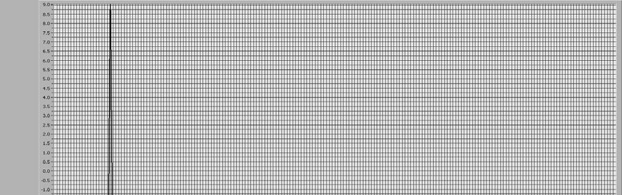
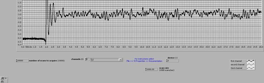
4 Where gravity drainage systems are used together with large size cover/grates which cannot be blocked by the 99-percentile man, or with multiple 19.8 suction outlets that do not mount flat and flush with the mounting surface, or with channel drain systems, or when SVRS is used with multiple 19.8 suction outlets that do not mount flat and flush with the mounting surface; the hazard of body and limb entrapment is properly addressed in the model building codes. The structural tests and fastening requirements included in the ASME 19.8 standard are intended to evaluate the structural integrity of small suction fittings, thereby addressing the problem of broken or missing suction cover/grates. Statistics show that missing or broken grates are one leading cause of body and limb entrapments. The 19.8 standard contains tests intended to reduce the potential of hair entrapment including hair entanglement-resistance performance testing and by establishing maximum allowable flowrates for listed products. The potential for hair entrapment is virtually eliminated by the use of proper fitted bathing caps. Mechanical entrapments cannot be entirely prevented since articles of apparel may become entrapped in covers/grates. Most state health codes address this issue by prohibiting jewelry and loose fitting clothing. Accepted Standards - Conclusions: It is the intent of the IRC and IBC to prevent a single direct suction drain opening from being the sole inlet to the suction side of the pump. Portable spas are not part of a structure and therefore are not required to meet the provisions of the codes. However, above-ground pools that utilize drains for recirculation must meet the anti-entrapment provisions of the codes. There is nothing in the code to imply that drains are required for recirculation. All pools and spas that incorporate direct suction systems must incorporate a system that conforms to the ANSI/ASME A standard. Pools that utilize gravity drainage systems or collector tanks without direct pump suction or pools that do not utilize drains for recirculation do not require the ANSI/ASME A certified/listed systems. INVESTIGATION Specifications and Parameters: The principal performance requirements utilized herein to investigate and evaluate certain purported safety embodiments are contained in the standard: a 15 pound buoyant blocking element must be released from the drain under test within an elapsed time of less than three seconds using one-hundred feet of suction piping and one hundred feet of discharge (return) piping loops. Tests were performed utilizing ½ and 3 horsepower (HP) pumps located 62 inches below the static water level in the test tank. A test stand was constructed as shown in Figure 1 to hold six feet of water over installed dual drains with three feet separating each drain sump. The drain sump under test has an aggregate cross-sectional (open) area of forty-four (44) square inches. A blocking element that is fifteen pounds buoyant is used to simulate an entrapment event pursuant to the standard specification. A full scale, 0-30 inch/hg pressure (vacuum) transducer capable of acquiring fifty readings each second is used to measure the vacuum condition resulting from a simulated blockage. The transducer is located within the sidewall of the sump under test. A data acquisition system is utilized to plot an inverted transposed waveform graph that shows the resulting vacuum condition of the simulated entrapment event over time. All tests were executed numerous times to insure consistency, repeatability, and accuracy of the resulting plots. Page 4 of 29
5 FIGURE 1. - COMPLETE TEST STAND Instrumentation: Calibrated (A2LA) instrumentation used for tests is listed as follows: National Instruments Lab-View Data Acquisition Software v7.1 Honeywell/Sensotec Vacuum Transducer(s) Model No. FPV/E Serial Flow meter - Signet 515 Rotor-X Sensor Model P51530-PO w/ digital indicator # To establish consistency and repeatability a minimum of three consecutive tests were plotted for each embodiment. However, only one representative plot is included in this report. All tests are conducted indoors and at a conditioned room temperature of approximately 73 Degrees F. Dual Drain Investigation: In the following tests dual drains are evaluated utilizing ½ HP and 3HP pumps in accordance with code-referenced standard The pumps are located below the static water level in the test tank. Two inch PVC schedule 40 suction and return piping loops are 100 in developed length. The drains are plumbed so that there is three feet of separation between each drain sump. The drain sump subjected to blockage during test has the cover removed. The other sump has a cover secured in place. See Figure 2. FIGURE 2. - DUAL DRAINS Page 5 of 29


6 1. In the first series of tests dual drains are evaluated using a 3 HP pump. One of the dual drains is closed off via a valve and the recorded flow in gallons per minute (gpm) is 78 gpm. The other dual drain is then blocked. Upon the blockage the resulting vacuum condition is plotted as shown in Figure 3. The differential pressure plotted is 32.9 in/hg. This results in an extended dynamic hold-down force of 719 pounds. FIGURE 3. Note: Initial reading at -6.0 in/hg is due to the water depth and the dynamic losses through the sump. 2. In the second series of tests dual drains are evaluated utilizing a ½ HP pump. One of the dual drains is closed off via a valve and the recorded flow is 46 gpm. The other dual drain is then blocked. Upon the blockage the resulting vacuum condition is plotted as shown in Figure 4. The differential pressure plotted is 31.0 in/hg. This results in an extended dynamic hold-down force of 677 pounds. 3. In the third series of tests dual drains are evaluated utilizing a 3 HP pump. With both of the dual drains open and flowing at 78 gpm the other dual drain is then blocked. Upon the blockage the resulting vacuum condition is plotted as shown in Figure 5. The differential pressure plotted is 3.0 in/hg. This results in an extended dynamic hold-down force of 65 pounds. 4. In the fourth series of tests dual drains are evaluated utilizing a ½ HP pump. With both of the dual drains open and flowing at 46 gpm the other dual drain is then blocked. Upon the blockage the resulting vacuum condition is plotted as shown in Figure 6. The differential pressure plotted is 1.30 in/hg. This results in a dynamic hold-down force of 28 pounds. Page 6 of 29


7 FIGURE 4. FIGURE 5. Page 7 of 29


8 FIGURE 6. Conclusions Dual Drain Investigation: If dual drains were the only means of entrapment prevention relied upon and one of the two drains were to become blocked due to leaves, trash, pool toys or otherwise, then the other drain would have an entrapment force of 719 pounds for a 3 HP pump and 677 pounds for a ½ HP pump. If a small child were to seal one drain, with the opposite drain open and flowing, the holddown force is 65 pounds at 78 gpm and 28 pounds at 46 gpm. Therefore, dual drains as a stand alone method cannot be safely relied upon for entrapment prevention given the potential for drain blockage and excessive dynamic suction forces. Florida Vent Investigation: In the following tests the Florida vent system together with dual drains is evaluated utilizing ½ HP and 3HP pumps in accordance with code-referenced standard The pump is located below the static water level in the test tank. Two inch PVC schedule 40 suction and return piping loops are 100 in developed length. The drains are plumbed so that there is three feet of separation between each drain sump. The drain sump subjected to blockage during the test has the cover removed. The other sump has a cover secured in place. See Figure 7. Page 8 of 29
9 FIGURE 7. FLORIDA VENT SYSTEM W/DUAL DRAINS 1. In the first series of tests the Florida Vent system is evaluated together with dual drains utilizing a 3HP pump. When at rest, the level of water in the vent pipe portion of the Florida vent system is equal to the water level in the test tank, as shown in Figure 7-1. One of the dual drains is closed off via a valve. After starting the 3 HP pump, the water level in the vent is allowed to stabilize and as such the recorded gallon per minute (gpm) flow is 78 gpm. The operating draw-down is at 60 inches, as shown in Figure 7-2. The other dual drain is then blocked. The vent pipe empties and air enters the suction piping, as shown in Figure 7-3. The blocking element failed to release within the required time. The pump was shut off and the element did not release until over one minute had elapsed. The differential pressure plotted is 5.2 in/hg, as shown in Figure 7-4. This results in an extended static differential hold-down force of 114 pounds. FIGURE 7-1 FIGURE 7-2 FLORIDA VENT - AT REST FLORIDA VENT - DRAW DOWN = WATER LEVEL IN VENT AFTER 3 HP PUMP START Page 9 of 29


10 FIGURE 7-3. FLORIDA VENT - BLOCKAGE = WATER LEVEL IN VENT BOTH DRAINS BLOCKED FIGURE In the second series of tests, the Florida Vent system is evaluated together with dual drains utilizing a ½ HP pump. The level of water in the vent pipe portion of the Florida Vent system, when at rest, is equal to the water level in the test tank, as shown in Figure 7-5. One of the dual drains is closed off via a valve. After starting the ½ HP pump the water level in the vent is allowed to stabilize and as such the recorded flow is 44 gpm. The operating draw-down is at 20.5 inches, as shown in Figure 7-6. The other dual drain is then blocked. The vent pipe empties and air enters the suction piping, as shown in Figure 7-7. The blocking element failed to release within the required time. The pump was shut off and the element did not release until over one minute had elapsed. The differential pressure plotted is 5.2 in/hg. This results in an extended static differential hold-down force of 114 pounds, as shown in Figure 7-8. Page 10 of 29
11 FIGURE 7-5. FLORIDA VENT - AT REST FIGURE 7-6. = WATER LEVEL IN VENT AFTER 1/2 HP PUMP START FLORIDA VENT SYSTEM FIGURE 7-7. FLORIDA VENT - BLOCKAGE = WATER LEVEL IN VENT BOTH DRAINS BLOCKED Page 11 of 29


12 FIGURE In the third series of tests the Florida Vent system is evaluated utilizing a 3 HP pump. When at rest, the level of water in the vent pipe portion of the Florida vent system is equal to the water level in the test tank, as shown in Figure 7-9. After starting the 3 HP pump, the water level in the vent is allowed to stabilize and as such the recorded flow is 78 gpm. The operating draw-down is at 27 inches, as shown in Figure With both of the dual drains open and flowing the other dual drain is then blocked. The draw-down upon the blockage is 63 inches, as shown in Figure Upon the blockage the resulting vacuum condition is plotted as shown in Figure The differential pressure plotted is 3.0 in/hg. The result is an extended dynamic hold-down force of 65 pounds. FIGURE 7-9. FIGURE FLORIDA VENT - AT REST FLORIDA VENT - DRAW DOWN = WATER LEVEL IN VENT AFTER 3 HP PUMP START Page 12 of 29


13 FIGURE FLORIDA VENT - BLOCKAGE = WATER LEVEL IN VENT AFTER 1 DRAIN BLOCKED FIGURE In the fourth series of tests the Florida vent system is evaluated utilizing a ½ HP pump. When at rest, the level of water in the vent pipe portion of the Florida vent system is equal to the water level in the test tank, as shown in Figure After starting the 1/2 HP pump, the water level in the vent is allowed to stabilize and as such the recorded flow is 44 gpm. The operating draw-down is at 10 inches, as shown in Figure With both of the dual drains open and flowing the other dual drain is then blocked. The drawdown upon the blockage is 20.5 inches, as shown in Figure Upon the blockage the resulting vacuum condition is plotted as shown in Figure The differential pressure plotted is 1.30 in/hg. This results in an extended hold-down force of 28.0 pounds. Page 13 of 29


14 FIGURE FIGURE = WATER LEVEL IN VENT AFTER 1/2 HP PUMP START FLORIDA VENT - AT REST FLORIDA VENT SYSTEM FIGURE FLORIDA VENT - BLOCKAGE = WATER LEVEL IN VENT AFTER 1 DRAIN BLOCKED FIGURE Page 14 of 29
15 Conclusions Florida Vent System Investigation: If the Florida vent system together with dual drains were the only means of entrapment prevention and one of the two drains were to become blocked due to leaves, trash, pool toys or otherwise, then the other drain has a static differential entrapment force of 114 pounds, at six feet pool depth on a standard eight inch, uncovered sump. If a small child were to seal one drain, with the opposite drain open and flowing, the dynamic hold down force would be 65 pounds at 78 gpm and 28 pounds at 44 gpm. Therefore, The Florida vent system together with dual drains cannot be safely relied upon for entrapment prevention given the potential for excessive dynamic and static hold down forces. U-Tube Vent System Investigation: In the following tests, dual drains are evaluated utilizing ½ HP and 3HP pumps in accordance with code-referenced standard The pumps are located below the static water level in the test tank. Two inch PVC schedule 40 suction and return piping loops are 100 in developed length. The drains are plumbed so that there is three feet of separation between each drain sump. The drain sump subjected to blockage during test has the cover removed. The other sump has a cover secured in place. See Figure In the first series of tests, the U-Tube Vent system is evaluated together with dual drains utilizing a 3HP pump, as shown in Figure 8. One of the dual drains is closed off via a valve. When at rest, the level of water in the vent pipe portion of the U-Tube vent system is equal to the water level in the test tank, as shown in Figure 8-1. After starting the 3 HP pump, the water level in the vent is allowed to stabilize and the recorded flow is 61 gpm. The operating draw-down is at 78 inches, as shown in Figure 8-2. The other dual drain is then blocked. The U-Tube vent pipe empties and air enters the suction piping, as shown in Figure 8-3. The blocking element is released within the required time, as shown in Figure 8-4. FIGURE 8. U-TUBE VENT SYSTEM W/DUAL DRAINS Page 15 of 29
16 FIGURE 8-1. "U" TUBE VENT SYSTEM AT REST TEE IS LOCATED 11" BELOW STATIC WATER LEVEL IN TANK FIGURE 8-2. "U" TUBE VENT SYSTEM DRAW-DOWN FIGURE 8-3. "U" TUBE VENT SYSTEM VENTING Page 16 of 29


17 FIGURE In the second series of tests the U-Tube Vent system is evaluated together with dual drains utilizing a ½ HP pump, as shown in Figure 8. One of the dual drains is closed off via a valve. When at rest, the level of water in the vent pipe portion of the U-Tube vent system is equal to the water level in the test tank, as shown in Figure 8-5. After starting the ½ HP pump the water level in the vent is allowed to stabilize and as such the recorded flow is 44 gpm. The operating drawdown is at 41 inches, as shown in Figure 8-6. The other dual drain is then blocked. FIGURE 8-5. FIGURE 8-6. "U" TUBE VENT SYSTEM AT REST "U" TUBE VENT SYSTEM DRAW-DOWN TEE IS LOCATED 11" BELOW STATIC WATER LEVEL IN TANK Page 17 of 29


18 FIGURE 8-7. "U" TUBE VENT SYSTEM VENTING FIGURE 8-8. The U-Tube vent pipe empties and air enters the suction piping, as shown in Figure 8-7. The blocking is released within the required time, as shown in Figure 8-8. Page 18 of 29
19 3. In the third series of tests the U-Tube Vent system is evaluated together with dual drains utilizing a 3HP pump, as shown in Figure 8. When at rest, the level of water in the vent pipe portion of the U-Tube vent system is equal to the water level in the test tank, as shown in Figure 8-9. After starting the 3 HP pump, the water level in the vent is allowed to stabilize and as such the recorded flow is 72 gpm. The operating draw-down is at 78 inches, as shown in Figure With both of the dual drains open and flowing the other dual drain is then blocked. The U-Tube vent pipe empties and air enters the suction piping, as shown in Figure The blocking element does not release within the required time, as shown in Figure The release time or time to return to zero differential is 3.7 seconds. FIGURE 8-9. FIGURE 8-10 "U" TUBE VENT SYSTEM AT REST "U" TUBE VENT SYSTEM DRAW-DOWN TEE IS LOCATED 11" BELOW STATIC WATER LEVEL IN TANK FIGURE "U" TUBE VENT SYSTEM VENTING Page 19 of 29


20 FIGURE In the fourth series of tests the U-Tube Vent system is evaluated together with dual drains utilizing a ½ HP pump, as shown in Figure 8. When at rest, the level of water in the vent pipe portion of the U-Tube vent system is equal to the water level in the test tank, as shown in Figure After starting the ½ HP pump, the water level in the vent is allowed to stabilize and as such the recorded flow is 42 gpm. The operating draw-down is at 31 inches, as shown in Figure With both of the dual drains open and flowing the other dual drain is then blocked. The U-Tube vent pipe does not vent, as shown in Figure The draw down upon the blockage is 42 inches. However, the blocking element was released within the required time, as shown in Figure FIGURE FIGURE "U" TUBE VENT SYSTEM AT REST "U" TUBE VENT SYSTEM DRAW-DOWN TEE IS LOCATED 11" BELOW STATIC WATER LEVEL IN TANK Page 20 of 29


21 FIGURE "U" TUBE VENT SYSTEM DRAW-DOWN FIGURE Conclusions U-Tube Vent Investigation: The U-Tube vent system together with dual drains performs in accordance with the accepted standards by releasing the blocking element within the required time for the test conditions 1, 2, and 4. The U-Tube vent system with dual drains fails to meet the standard for test condition 3. In all cases, the pumps would not re-prime between each test. The only way to re-prime the pumps was to manually bleed off the air that remained in the suction piping. Note: One of the ½ HP pumps burned-out during the series of tests and had to be replaced. Page 21 of 29
22 Steven s Vent System Investigation: In the following tests, the Steven s vent system together with dual drains is evaluated utilizing ½ HP and 3HP pumps in accordance with code-referenced standard The pump is located below the static water level in the test tank. Two inch PVC schedule 40 suction and return piping loops are 100 in developed length. The drains are plumbed so that there is three feet of separation between each drain sump. The drain sump subjected to blockage during the test has the cover removed. The other sump has a cover secured in place. See Figure 9. FIGURE 9. STEVEN S VENT SYSTEM 1. In the first series of tests the Steven s Vent system is evaluated together with dual drains utilizing a 3HP pump, as shown in Figure 9. One of the dual drains is closed off via a valve. When at rest, the level of water in the vent pipe portion of the Steven s vent system is equal to the water level in the test tank, as shown in Figure 9-1. After starting the 3 HP pump, the water level in the vent is allowed to stabilize and as such the recorded flow is 44 gpm. The operating draw-down is at 10 inches, as shown in Figure 9-2. The other dual drain is then blocked. FIGURE 9-1. FIGURE 9-2. STEVEN'S VENT OPERATING DRAW-DOWN STEVEN'S VENT SYSTEM AT REST COLLECTOR TEE CENTERLINE LOCATED 11" BELOW STATIC WATER LEVEL COLLECTOR TEE CENTERLINE LOCATED 11" BELOW STATIC WATER LEVEL Page 22 of 29


23 FIGURE 9-3. STEVEN'S VENT SYSTEM VENTING COLLECTOR TEE CENTERLINE LOCATED 11" BELOW STATIC WATER LEVEL FIGURE 9-4. The Steven s vent pipe empties and air enters the suction piping, as shown in Figure 9-3. The blocking element is released within the required time, as shown in Figure 9-4. Page 23 of 29
24 2. In the second series of tests the Steven s Vent system is evaluated together with dual drains utilizing a ½ HP pump, as shown in Figure 9. One of the dual drains is closed off via a valve. When at rest, the level of water in the vent pipe portion of the Steven s vent system is equal to the water level in the test tank, as shown in Figure 9-5. After starting the 1/2 HP pump, the water level in the vent is allowed to stabilize and as such the recorded flow is 44 gpm. The operating draw-down is at 6.5 inches, as shown in Figure 9-6. The other dual drain is then blocked. FIGURE 9-5. STEVEN'S VENT SYSTEM AT REST COLLECTOR TEE CENTERLINE LOCATED 11" BELOW STATIC WATER LEVEL FIGURE 9-6. STEVEN'S VENT OPERATING DRAW-DOWN COLLECTOR TEE CENTERLINE LOCATED 11" BELOW STATIC WATER LEVEL FIGURE 9.7. STEVEN'S VENT SYSTEM VENTING COLLECTOR TEE CENTERLINE LOCATED 11" BELOW STATIC WATER LEVEL Page 24 of 29


25 FIGURE 9-8. The Steven s vent pipe empties and air enters the suction piping, as shown in Figure 9-7. The blocking element is released within the required time, as shown in Figure In the third series of tests the Steven s Vent system is evaluated together with dual drains utilizing a 3HP pump, as shown in Figure 8. When at rest, the level of water in the vent pipe portion of the U-Tube vent system is equal to the water level in the test tank, as shown in Figure 9-9. After starting the 3 HP pump, the water level in the vent is allowed to stabilize and as such the recorded flow is 46 gpm. The operating draw-down is at 8 inches, as shown in Figure With both of the dual drains open and flowing the other dual drain is then blocked. The Steven s vent pipe empties and air enters the suction piping, as shown in Figure The blocking element is releases within the required time, as shown in Figure FIGURE 9-9. FIGURE STEVEN'S VENT SYSTEM AT REST STEVEN'S VENT OPERATING DRAW-DOWN COLLECTOR TEE CENTERLINE LOCATED 11" BELOW STATIC WATER LEVEL COLLECTOR TEE CENTERLINE LOCATED 11" BELOW STATIC WATER LEVEL Page 25 of 29


26 FIGURE STEVEN'S VENT SYSTEM VENTING COLLECTOR TEE CENTERLINE LOCATED 11" BELOW STATIC WATER LEVEL FIGURE In the fourth series of tests the Steven s Vent system is evaluated together with dual drains utilizing a ½ HP pump, as shown in Figure 9. One of the dual drains is closed off via a valve. When at rest, the level of water in the vent pipe portion of the Steven s vent system is equal to the water level in the test tank, as shown in Figure 9-13 After starting the 1/2 HP pump, the water level in the vent is allowed to stabilize and as such the recorded flow is 44 gpm. The operating draw-down is at 7.0 inches, as shown in Figure The other dual drain is then blocked. The Steven s vent pipe empties and air enters the suction piping, as shown in Figure The blocking element is releases within the required time, as shown in Figure Page 26 of 29


27 FIGURE FIGURE STEVEN'S VENT SYSTEM AT REST COLLECTOR TEE CENTERLINE LOCATED 11" BELOW STATIC WATER LEVEL STEVEN'S VENT OPERATING DRAW-DOWN COLLECTOR TEE CENTERLINE LOCATED 11" BELOW STATIC WATER LEVEL FIGURE STEVEN'S VENT SYSTEM VENTING COLLECTOR TEE CENTERLINE LOCATED 11" BELOW STATIC WATER LEVEL FIGURE Page 27 of 29
28 Conclusions Steven s Vent System Investigation: The Steven s vent together with dual drains performs within the accepted standards by releasing the blocking element within the required time under all test conditions. Flows are limited based upon piping configuration, pipe sizing, and available draw-down. The system s collector tee is set at 11 which equates to about fifteen pounds of static differential force on a standard 8 round (44 square inch open area) uncovered drain sump. If the collector tee is set below 11 the static differential force may not permit the blocking element to release with the required time. CLOSING STATEMENTS: The 2004/2005 ICC code change cycle was concluded at the Final Action Hearings conducted by the ICC in Detroit, Michigan, during the last part of September and early October of These hearings were the last chance to effect any modifications to the 2006 set of ICC model codes. During the 2004/2005 code change cycle, the Association of Pool and Spa Professionals (APSP) [formally known as the National Spa and Pool Association (NSPI)] submitted code modifications to the International Residential Code (IRC) and the International Building Code (IBC). See International Code Council 2004/2005 Code Development Cycle, Errata to the 2004/2005 Proposed Changes to the International Codes Item RB234-04/05, Part I IRC and Part II IBC The ICC membership rejected the APSP proposals in favor of the current code language shown above. APSP representatives argued that the options delineated in the current IBC/IRC did not address all entrapment hazards, while their proposal did. If the APSP proposals were to have been accepted they would have permitted dual drains and non-standard means as stand alone methods for entrapment mitigation. This report demonstrates that dual drains cannot be safely relied upon for entrapment prevention. The APSP proposals also included anti-entrapment methods that have not demonstrated compliance with the code-referenced standard. APSP representatives have purported to address evisceration in their ICC proposals. The standard contains the following statement: WARNING: Due to the lack of physiological data, it cannot be concluded that a Safety Vacuum Release System will eliminate the potential for disembowelment. Therefore this standard does not purport to address disembowelment safety concerns. APSP did not present any new data to support a claim that their proposals addressed evisceration. Therefore, to date, the issue of evisceration mitigation remains largely unresolved. The reason it continues to be largely unresolved is still due to the lack of physiological data. It is interesting to note, however, that no evisceration injuries or related-deaths have been reported to date where gravity drainage systems are utilized with relatively large covers with flow velocities limited to less than 1.5 feet per second. In many circumstances pool builders and enforcement personnel have relied and are relying on methods of entrapment avoidance that do not meet any accepted performance standard. This may prove to be problematic. This lack of accepted referenced standards for the entrapment protection systems forces enforcement personnel to require engineering for pool and spa recirculation systems. Even though such systems are sealed by an engineer, the pool builder s, the engineer s and enforcement personnel s liability exposure may still exist, should a related loss occur on any non-standard system. The International Codes are developed using the highest standards to maintain integrity of the resulting models and to insure that all materially affected interests have input. To successfully mitigate excessive liability exposure, the minimum performance levels prescribed in the International Code Council s model codes must be adhered to. Page 28 of 29
29 Biography Gary S. Duren is the proponent of record of the ICC anti-entrapment provisions contained within the latest editions of the International Building Code and International Residential Code, IBC Section and ICC Section AG106, respectively; a member of the American Society of Mechanical Engineering (ASME) A112 Committee; ASME Project Team Leader A ; Deputy Project Team Leader ASME A ; Charter member of Florida Building Commission-Plumbing Technical Advisory Committee; and member of the Florida Association of Plumbing, Mechanical and Gas Inspectors Board of Directors; as such, the opinions expressed herein are not to be construed as any official representation of any committee or board above referenced, but are solely an independent analysis provided by contract to the PSC. All Rights Reserved 2005, Inc... May not be used without written permission Page 29 of 29
Understanding and Compliance of the Virginia Graeme Baker Pool & Spa Safety Act
 Understanding and Compliance of the Virginia Graeme Baker Pool & Spa Safety Act Sponsored by the U.S. Consumer Product Safety Commission Presented By: Rick English, Certified Building Professional, CPOI
New England Municipal Building Officials Preventing Drowning and Suction Entrapment through Code Compliance
 New England Municipal Building Officials Preventing Drowning and Suction Entrapment through Code Compliance 2009 International Family of Codes Swimming Pools and Spas 2009 International Building Code 2009
CUSTOMER ASSISTANCE GUIDE BUILDING PERMIT APPLICATION SUBMITTAL REQUIREMENTS
 CUSTOMER ASSISTANCE GUIDE BUILDING PERMIT APPLICATION SUBMITTAL REQUIREMENTS SWIMMING POOLS (IN-GROUND OR ABOVE-GROUND), SPAS AND HOT TUBS (CONTAINS WATER OVER 24 INCHES DEEP) Please read all of the following
ANTI-ENTRAPMENT PLAN
 ANTI-ENTRAPMENT PLAN Anti-Entrapment Plan Presenters: Kevin Jeroncic, Alberta Health Services Wade Goin, Alberta Health Services Kelly Carter, Lifesaving Society Session Objectives Defining Entrapment
Dan Johnson, CBP Swim, Incorporated Lead Dog Aquatic Consulting
 Dan Johnson, CBP Swim, Incorporated Lead Dog Aquatic Consulting APSP/ANSI-7 Writing Committee APSP/ANSI/ICC-15 Writing Committee APSP/ANSI/ICC-5 Writing Committee (Chairman) International Swimming Pool
SWIMMING POOLS/SPAS/HOT TUBS PLAN REVIEW GUIDE SHEET
 SWIMMING POOLS/SPAS/HOT TUBS PLAN REVIEW GUIDE SHEET Sect. 106-748, City Code of Ordinances: Regulations are applicable to both above and inground swimming pools, spas and hot tubs. POOL PLACEMENT Measurement
POOL BARRIER AMENDMENTS & GUIDELINES: APPENDIX G SWIMMING POOLS, SPAS AND HOT TUBS
 SECTION AG101 - GENERAL POOL BARRIER AMENDMENTS & GUIDELINES: APPENDIX G SWIMMING POOLS, SPAS AND HOT TUBS AG101.1 General. The requirements of this appendix shall apply to the design and construction
TITLE XIV POOL AND SPA SAFETY
 Virginia Graeme Baker Pool and Spa Safety Act. 15 USC 8001 note. 15 USC 8001. TITLE XIV POOL AND SPA SAFETY SEC. 1401. SHORT TITLE. This title may be cited as the Virginia Graeme Baker Pool and Spa Safety
COMPLIANCE WITH STANDARDS, REGULATIONS AND ORDINANCES
 INTRODUCTION TO THE BUILDER Your safety and that of your family and friends is of vital concern to all of us. When installed and used properly, swimming pools provide many hours of safe, healthy fun and
The Virginia Graeme Baker Pool and Spa Safety Act. by and does not necessarily represent the views of the Commission.
 The Virginia Graeme Baker Pool and Spa Safety Act This information was prepared by the CPSC staff; it has not been approved This information was prepared by the CPSC staff; it has not been approved by
TOWN OF FARMINGTON DEPARTMENT OF PUBLIC WORKS & DEVELOPMENT SERVICES. Russell M. Arnold Jr., P.E. Director/Town Engineer (860)
") TOWN OF FARMINGTON DEPARTMENT OF PUBLIC WORKS & DEVELOPMENT SERVICES Russell M. Arnold Jr., P.E. Director/Town Engineer (860) 675-2305 BUILDING, ENGINEERING, PLANNING and ZONING DIVISIONS Christopher Foryan,
TOWN OF FARMINGTON DEPARTMENT OF PUBLIC WORKS & DEVELOPMENT SERVICES Russell M. Arnold Jr., P.E. Director/Town Engineer (860) 675-2305 BUILDING, ENGINEERING, PLANNING and ZONING DIVISIONS Christopher Foryan,
MDX² INSTALLATION MANUAL (RETROFIT FIBERGLASS, VINYL & CONCRETE POOLS WITH MDX)
") Only for Pools with an existing MDX sump ANTI-ENTRAPMENT DEBRIS DRAIN MDX² INSTALLATION MANUAL (RETROFIT FIBERGLASS, VINYL & CONCRETE POOLS WITH MDX) Safety compliant according to the Virginia Graeme Baker
Only for Pools with an existing MDX sump ANTI-ENTRAPMENT DEBRIS DRAIN MDX² INSTALLATION MANUAL (RETROFIT FIBERGLASS, VINYL & CONCRETE POOLS WITH MDX) Safety compliant according to the Virginia Graeme Baker
TITLE XIV POOL AND SPA SAFETY
 1 2 4 5 TITLE XIV POOL AND SPA SAFETY SEC. 01. SHORT TITLE. This title may be cited as the Virginia Graeme Baker Pool and Spa Safety Act. SEC. 02. FINDINGS. Congress finds the following: (1) Of injury-related
Swimming Pools, Hot Tubs and Spas
 OLATHE FIRE DEPARTMENT BUILDING CODES 1225 S. Hamilton Circle Olathe, KS 66061 / Main: (913) 971-7900 / Fax: (913) 971-9812 Swimming Pools, Hot Tubs and Spas Definitions: Swimming Pool- Any structure intended
U.S. CONSUMER PRODUCT SAFETY COMMISSION WASHINGTON, D.C November 23, 2004
 U.S. CONSUMER PRODUCT SAFETY COMMISSION WASHINGTON, D.C. 20207 November 23, 2004 Dear Colleague: Since the release of Guidelines for Entrapment Hazards: Making Pools and Spas Safer (guidelines) in January
Chapter 10 SWIMMING POOLS
 4-10-1: COMPLIANCE REQUIRED: Chapter 10 SWIMMING POOLS It shall be unlawful to construct, maintain, install or enlarge any swimming pool in the City except in compliance with the provisions of this Chapter.
GUIDELINE FOR MITIGATING SUCTION HAZARDS IN POOLS
 GUIDELINE FOR MITIGATING SUCTION HAZARDS IN POOLS JUNE 2014 HEALTH AUTHORITY RECREATIONAL WATER COUNCIL Mitigating Suction Hazards in Swimming Pools Main-drains and other suction points in swimming pools
Swimming Pool Requirements
 Swimming Pool Requirements 1. Definitions: Approved Safety Pool Cover. Means a manually or power-operated safety pool cover that meets all of the performance standards of the American Society for Testing
Summary of Substantive Changes between the 2003 and the 2014 editions of ANSI/APSP/ICC 1 American National Standard for Public Swimming Pools
 Summary of Substantive Changes between the 2003 and the 2014 editions of ANSI/APSP/ICC 1 American National Standard for Public Swimming Pools Presented to the IAPMO Standards Review Committee on December
2009 NEW MEXICO SWIMMING POOL, SPA AND HOT TUB CODE
 TITLE 14 CHAPTER 8 PART 3 HOUSING AND CONSTRUCTION PLUMBING CODES 2009 NEW MEXICO SWIMMING POOL, SPA AND HOT TUB CODE 14.8.3.1 ISSUING AGENCY: Construction Industries Division (CID) of the Regulation and
I. Site Information. Pump Information
 California Department of Public Health Compliance Form for Public Pools and Spas Health and Safety Code Sections 116064.1 and 116064.2,> INSTRUCTIONS FOR COMPLETING THE COMPLIANCE FORM Use one form for
VIRGINIA GRAEME BAKER POOL & SPA SAFETY ACT
 VIRGINIA GRAEME BAKER POOL & SPA SAFETY ACT CPSC STAFF S GUIDE TO COMPLYING WITH THE LAW By December 19, 2008, ALL public pool owners/operators must: Install drain covers that meet the ANSI/ASME A112.19.8
Jennifer Hatfield FSPA Government Relations Consultant J. Hatfield & Associates, PL
 Jennifer Hatfield FSPA Government Relations Consultant J. Hatfield & Associates, PL Topics to cover: Pool & Spa Energy Code Requirements Residential Code Requirements Building (Public) Code Requirements
POOL & SPA/HOT TUB APSP STANDARDS AS REFERENCED IN THE 2009 INTERNATIONAL CODES
 POOL & SPA/HOT TUB APSP STANDARDS AS REFERENCED IN THE 2009 INTERNATIONAL CODES APSP Standards: As Referenced in the 2009 International Codes Publication Date: June 2010 ISBN-978-1-58001-662-9 PUBLISHED
NOTICE. SDX HIGH FLOW SAFETY DRAIN For Concrete, vinyl & equalizer pools OWNER S MANUAL & INSTALLATION GUIDE
 NSF/ANSI 50 SDX HIGH FLOW SAFETY DRAIN For Concrete, vinyl & equalizer pools OWNER S MANUAL & INSTALLATION GUIDE VGB 2008 COMPLIANT MDX 2 & SDX DRAINS ARE COMPLIANT WITH THE VIRGINIA GRAEME BAKER ACT 2008.
PUBLIC SPA CHECKLIST. Planning and Building Department City of Mississauga 300 City Centre Drive, 3th Floor Mississauga ON L5B 3C1
 Planning and Building Department City of Mississauga 300 City Centre Drive, 3th Floor Mississauga ON L5B 3C1 PUBLIC SPA CHECKLIST This checklist is prepared for purposes of convenience only. For accurate
NOTICE WARNING MDX-R3 FOR FIBERGLASS POOLS OWNER S MANUAL AND INSTALLATION GUIDE SUBMERGED SUCTION OUTLET FOR MULTIPLE DRAIN USE FOR USE ON FLOOR
 MDX-R3 FOR FIBERGLASS POOLS OWNER S MANUAL AND INSTALLATION GUIDE SUBMERGED SUCTION OUTLET FOR MULTIPLE DRAIN USE FOR USE ON FLOOR SEE SPECIAL INSTRUCTIONS FOR CALIFORNIA ON PAGE 1 Safety compliant according
Installation Operation Maintenance
 682 Seal Cooler New generation seal cooler to meet and exceed the seal cooler requirements stated in the 4th Edition of API Standard 682 Installation Operation Maintenance Experience In Motion Description
Welcome to the PMG Educational Program. Sponsored by:
 Welcome to the PMG Educational Program Sponsored by: www.iccsafe.org/conference #ICCAC18 Today s Presenter Layers of Protection 2018 ISPSC Carvin DiGiovanni Vice President, Technical and Standards Association
G.B. Collins Engineering, P.A. Comments to Proposed Code Modification SW7074-A1
 G.B. Collins Engineering, P.A. Comments to Proposed Code Modification SW7074-A1 I. REFERENCES: CURRENT CODE PROVISIONS Florida Building Code, 5th Edition (2014) Chapter 4 Special Detailed Requirements
WATER HEATER THERMAL EXPANSION TANKS Owner s Manual. Safety Instructions Installation Maintenance Warranty. Models: 2-5 Gallon Capacity
 WATER HEATER THERMAL EXPANSION TANKS Owner s Manual Safety Instructions Installation Maintenance Warranty Models: 2-5 Gallon Capacity Thank You for purchasing this Thermal Expansion Tank. Properly installed
WORCESTER COUNTY HEALTH DEPARTMENT PRE-OPENING GUIDE SEMI PUBLIC POOLS 1. POOL WALLS AND BOTTOM SMOOTH, LIGHT COLORED AND EASILY CLEANABLE. (.
 WORCESTER COUNTY HEALTH DEPARTMENT PRE-OPENING GUIDE SEMI PUBLIC POOLS A. DECKS 1. POOL WALLS AND BOTTOM SMOOTH, LIGHT COLORED AND EASILY CLEANABLE. (.13) 2. LIFELINE IN PLACE AND SECURE AND A 4" MINIMUM
Jackson County Department of Public Health Application to Construct, Install, Remodel or Modify a Public Swimming Pool
 Jackson County Department of Public Health 538 Scotts Creek Rd. Suite 100 Sylva, NC 28779 Tel: 828-586-8994 FAX: 828-586-3493 Shelley Carraway DIRECTOR Jackson County Department of Public Health Application
Information on RESIDENTIAL SWIMMING POOLS
 SECTION 473 (North Cornwall Township Zoning Ordinance page 286) 473.A. Within all Zones swimming pools are permitted accessory uses to a principal residence provided that the applicant has met his/her
RESIDENTIAL SWIMMING POOLS AND SPAS A GUIDE FOR HOMEOWNERS
 RESIDENTIAL SWIMMING POOLS AND SPAS A GUIDE FOR HOMEOWNERS City of Redding 777 Cypress Avenue Redding CA 96001 Telephone: (530) 225-4013 FAX: (530) 225-4360 A Swimming Pool is any body of water 18 inches
APPLICATION FOR A PERMIT TO CONSTRUCT OR ALTER A PUBLIC SWIMMING POOL, SPA POOL, WADING POOL OR FOUNTAIN
 CLACKAMAS COUNTY COMMUNITY HEALTH DIVISION ENVIRONMENT & HEALTH SERVICES APPLICATION FOR A PERMIT TO CONSTRUCT OR ALTER A PUBLIC SWIMMING POOL, SPA POOL, WADING POOL OR FOUNTAIN APPLICATION IS HEREBY MADE
Cynthia Arias Pollution Control Coordinator
 Cynthia Arias Pollution Control Coordinator cynthia.arias@cityofcarrollton.com 972-466-3059 28 cities surveyed 100% were inspecting public and semi-public pools Based on Texas Department of State Health
OIL SUPPLY SYSTEMS ABOVE 45kW OUTPUT 4.1 Oil Supply
 OIL SUPPLY SYSTEMS ABOVE 45kW OUTPUT 4.1 Oil Supply 4.1.1 General The primary function of a system for handling fuel oil is to transfer oil from the storage tank to the oil burner at specified conditions
NOTICE WARNING DANGER SDX2 HIGH FLOW SAFETY DRAIN FOR CONCRETE OWNER S MANUAL MAINTENANCE & INSTALLATION GUIDE. VGB 2008 Compliant
 NSF/ANSI 50 VGB 2008 Compliant MADE IN USA SDX2 HIGH FLOW SAFETY DRAIN FOR CONCRETE OWNER S MANUAL MAINTENANCE & INSTALLATION GUIDE SUBMERGED SUCTION OUTLET FOR SINGLE OR MULTIPLE DRAIN USE FOR USE ON
Mecklenburg County Health Ordinance Rules Governing Residential Swimming Pools
 Mecklenburg County Health Ordinance Rules Governing Residential Swimming Pools Mecklenburg County Health Department 700 N. Tryon Street, Suite 211 Charlotte, North Carolina 28202-2236 Phone (704) 336-5103
MDX-R3 FOR ADJUSTABLE CONCRETE POOLS OWNER S MANUAL AND INSTALLATION GUIDE
 MDX-R3 FOR ADJUSTABLE CONCRETE POOLS OWNER S MANUAL AND INSTALLATION GUIDE SUBMERGED SUCTION OUTLET FOR MULTIPLE DRAIN USE FOR USE ON FLOOR SEE SPECIAL INSTRUCTIONS FOR CALIFORNIA ON PAGE 7 Safety compliant
Air Eliminators and Combination Air Eliminators Strainers
 Description Air Eliminators and Combination Air Eliminator Strainers are designed to provide separation, elimination and prevention of air in piping systems for a variety of installations and conditions.
WORCESTER COUNTY HEALTH DEPARTMENT PRE-OPENING GUIDE RECREATIONAL POOLS 2. DECK AND COPING MUST BE IN GOOD REPAIR AND PROPERLY DRAINED. (.
 A. DECKS WORCESTER COUNTY HEALTH DEPARTMENT PRE-OPENING GUIDE RECREATIONAL POOLS 1. FENCING MUST BE IN GOOD REPAIR. (.21) A. MINIMUM 6 FT FOR MAIN POOL. B. MINIMUM 3 FT FOR WADING POOL SEPARATION FENCE.
Saskatchewan Health S A WHIRLPOOL DESIGN/OPERATIONAL T C H E W STANDARDS. Updated 02/00
 Saskatchewan Health S A S K A T C H E W A N WHIRLPOOL DESIGN/OPERATIONAL STANDARDS Updated 02/00 FOREWORD These standards should be read in conjunction with The Swimming Pool Regulations, 1999. Saskatchewan
BUILDING STANDARDS INFORMATION BULLETIN 17-08
 DEPARTMENT OF GENERAL SERVICES 2525 Natomas Park Drive, Suite 130 Sacramento, California 95833-2936 (916) 263-0916 FAX (916) 263-0959 GOVERNOR EDMUND G. BROWN JR BUILDING STANDARDS INFORMATION BULLETIN
Installation Manual. Model # SF-3W 9/16/03 REV 1. Arch Chemicals, Inc Lower River Road. P.O. Box 800 Charleston, TN PULSAR
 Installation Manual Model # SF-3W Arch Chemicals, Inc. 1200 Lower River Road. P.O. Box 800 Charleston, TN 37310-0800 1-800-4-PULSAR 9/16/03 REV 1 Product Stewardship MAKING THE WORLD A BETTER PLACE Arch
Information Required on Building Permit Applications and Building Plans for the Installation of Swimming Pools, Spas, and Hot Tubs
 CASS COUNTY, MISSOURI BUILDING CODES, ENVIRONMENTAL HEALTH AND ZONING DEPARTMENT 30508 S. West Outer Road, Harrisonville, MO 64701 P- (816) 380-8134 F- (816) 380-8130 Information Required on Building Permit
Office Use Only Fee Paid
 WASHOE COUNTY HEALTH DISTRICT ENVIRONMENTAL HEALTH SERVICES DIVISION 1001 East Ninth Street PO Box 11130 Reno, Nevada 89520 Telephone (775) 328-2434 Fax (775) 328-6176 www.washoecounty.us/health APPLICATION
GWINNETT COUNTY SWIMMING POOL PLAN REVIEW CHECKLIST
 GWINNETT COUNTY SWIMMING POOL PLAN REVIEW CHECKLIST Pool Name: Address: Contractor: Phone: Number of Pools Applied for: GENERAL INFORMATION Plan review paid Pool Piping plan stamped by Design Professional.
The purpose of this brochure is to explain to owners and contractors the City of Burnaby s requirements for private swimming pools.
 Building Information BURNABY PLANNING & BUILDING DEPARTMENT Swimming Pools The purpose of this brochure is to explain to owners and contractors the City of Burnaby s requirements for private swimming pools.
CIPHI 2017 Annual Education Conference
 CIPHI 2017 Annual Education Conference Michael Wu, M. Sc., P.Eng. Public Health Engineer, VCH Jessica Ip, BSc(Hons), MBA, CPHI(C) Senior Environmental Health Officer, VCH Pool Suction Hazards Contents
AS AS Australian Standard. Spa pools. Part 2: Private spas. This is a free 6 page sample. Access the full version online.
 AS 2610.2 2007 AS 2610.2 2007 Australian Standard Spa pools Part 2: Private spas This Australian Standard was prepared by Committee CS-059, Spa Pools. It was approved on behalf of the Council of Standards
Irrigation System Winterization and Pressurization Procedures
 Irrigation System Winterization and Pressurization Procedures Introduction Any time that an irrigation system is filled and pressurized, or when the system is drained and water flushed from the system,
Cover Page for Lab Report Group Portion. Head Losses in Pipes
 Cover Page for Lab Report Group Portion Head Losses in Pipes Prepared by Professor J. M. Cimbala, Penn State University Latest revision: 02 February 2012 Name 1: Name 2: Name 3: [Name 4: ] Date: Section
ROCKDALE COUNTY NEW SWIMMING POOL PLAN REVIEW
 ROCKDALE COUNTY NEW SWIMMING POOL PLAN REVIEW Pool Name: Address: Contractor: Phone: Number of Pools Applied for: The following is a list of facility requirements for opening a public pool. Read each requirement
Chapter 23. Swimming Pools
 Chapter 23 Swimming Pools Part 1 Swimming Pools 23-101. Notification in Writing Required 23-102. Purpose 23-103. Construction Permit and Approval 23-104. Pools Are to Be Surrounded by Fence or Walls 23-105.
Chapter 808 Swimming Pools Ordinance
 CHAPTER 808 SWIMMING POOLS Section Chapter 808 Swimming Pools Ordinance 808.010 Citation of Chapter and Scope 808.020 Definitions 808.025 Aquatic Advisory Board 808.030 Rules and Regulations 808.040 Method
LAKOS Waterworks. PWC Series Sand Separators. Installation & Operation Manual LS-829 (10/12)
") LAKOS Waterworks PWC Series Sand Separators Installation & Operation Manual LS-829 (10/12) Table of Contents Separator Operation... 3 Individual Model Details.... 4 Flow vs. Pressure Loss Chart 4 Installation
LAKOS Waterworks PWC Series Sand Separators Installation & Operation Manual LS-829 (10/12) Table of Contents Separator Operation... 3 Individual Model Details.... 4 Flow vs. Pressure Loss Chart 4 Installation
BERMUDA GUNITE SKIMMER FOR SWIMMING POOLS
 1 1 1 BERMUDA GUNITE SKIMMER FOR SWIMMING POOLS INSTALLATION AND USER S GUIDE Rev. G 6-26-12 IMPORTANT SAFETY INSTRUCTIONS READ AND FOLLOW ALL INSTRUCTIONS SAVE THESE INSTRUCTIONS MASTERTEMP Pool and Spa
Summary of Substantive Changes between the 1999 and the 2014 editions of ANSI/APSP/ICC 3 Permanently Installed Residential Spas
 Summary of Substantive Changes between the 1999 and the 2014 editions of ANSI/APSP/ICC 3 Permanently Installed Residential Spas Presented to the IAPMO Standards Review Committee on January 8, 2018 General:
Dual-Main-Drain Suction-Entrapment Test Report
 International Journal of Aquatic Research and Education Volume 2 Number 3 Article 2 8-1-2008 Dual-Main-Drain Suction-Entrapment Test Report William N. Rowley National Swimming Pool Foundation, info@rowleyinternational.com
Australian Standard. Swimming pool safety. Part 3: Water recirculation systems AS AS
 AS 1926.3 2003 AS 1926.3 Australian Standard Swimming pool safety Part 3: Water recirculation systems This Australian Standard was prepared by Committee CS-034, Safety of Private Swimming Pools. It was
1 Exam Prep NSF/ANSI Tabs and Highlights
 1 Exam Prep NSF/ANSI 50 2015 Tabs and Highlights These 1 Exam Prep Tabs are based on ANSI/NSF 50-2015, Equipment for Swimming Pools, Spas, Hot Tubs and Other Recreational Water Facilities. Each 1 Exam
Introducing the 2015 ISPSC
 Introducing the 2015 ISPSC International Swimming Pool and Spa Code (ISPSC) Goal The goal of this seminar is to highlight the 2015 International Swimming Pool & Spa Code (ISPSC). 2012 ISPSC Introduction
AUTOMATIC (POWERED)POOL SAFETY COVERS AS AN ALTERNATE TO FENCING ONE SIZE DOESN T FIT ALL
POOL SAFETY COVERS AS AN ALTERNATE TO FENCING ONE SIZE DOESN T FIT ALL") AUTOMATIC (POWERED)POOL SAFETY COVERS AS AN ALTERNATE TO FENCING ONE SIZE DOESN T FIT ALL What is the purpose of a pool fencing bylaw? To reduce residential drowning TYPES OF FENCING Perimeter Fencing-
AUTOMATIC (POWERED)POOL SAFETY COVERS AS AN ALTERNATE TO FENCING ONE SIZE DOESN T FIT ALL What is the purpose of a pool fencing bylaw? To reduce residential drowning TYPES OF FENCING Perimeter Fencing-
AC : MEASUREMENT OF HYDROGEN IN HELIUM FLOW
 AC 2010-2145: MEASUREMENT OF HYDROGEN IN HELIUM FLOW Randy Buchanan, University of Southern Mississippi Christopher Winstead, University of Southern Mississippi Anton Netchaev, University of Southern Mississippi
Existing Rule Language Compared to Proposed Rule Language
 Existing Rule Language Compared to Proposed Rule Language MINNESOTA RULES, CHAPTER 4717; REVISOR S ID NUMBER 4442 The following table is a summary of existing and proposed rules. For complete regulations
List of Forms. Form Description Page No. Form Commercial Swimming Pool Discharge Application Form 31-4
 City of Columbia Engineering Regulations PART 31: SPECIFICATIONS FOR COMMERCIAL SWIMMING POOL BACKWASH AND DRAINAGE Table of Contents Paragraph Description Page No. 31.1 General 31-1 31.2 Definitions 31-1
Requirements for Swimming Pools
 Requirements for Swimming Pools A B-100 permit from Northeast District Dept. of Health, a Zoning Permit and a Building Permit are required. An Engineered Stamped plan must be submitted with any permit
BS Series Basket Strainer
 BS Series Basket Strainer Operating, Installation, & Maintenance Manual Corrosion Resistant Fluid and Air Handling Systems. Dated 04-26-12 PRESSURE DROP SIMTECH strainers are engineered to offer the lowest
A112 STANDARDS STATUS REPORT
 A112 STANDARDS STATUS REPORT DESIGNATION & TITLE STATUS RESPONSIBILITY A112.1.2 2012 (R2017) Air Gaps in Plumbing Systems (For Plumbing Fixtures and Water- Connected Receptors) RC #08-1056, PINS #284 LB
CHAPTER XXII SWIMMING POOLS 22 1 CONFORMITY REQUIRED.
 CHAPTER XXII SWIMMING POOLS 22 1 CONFORMITY REQUIRED. 22-1.1 General. Pools used for swimming or bathing shall be in conformity with the requirements of this chapter. However, these regulations shall not
KERN COUNTY PUBLIC HEALTH SERVICES DEPARTMENT ENVIRONMENTAL HEALTH DIVISION
 KERN COUNTY PUBLIC HEALTH SERVICES DEPARTMENT ENVIRONMENTAL HEALTH DIVISION 2700 M Street, Suite 300 Bakersfield, CA 93301 Phone (661) 862-8740 Fax (661) 862-8701 POOL DATA PUBLIC SWIMMING POOL, SPA, WADING
Cover Page for Lab Report Group Portion. Pump Performance
 Cover Page for Lab Report Group Portion Pump Performance Prepared by Professor J. M. Cimbala, Penn State University Latest revision: 02 March 2012 Name 1: Name 2: Name 3: [Name 4: ] Date: Section number:
5. Clearances- Fingerprinting and Training Requirements. 7. Record Keeping and Reporting Responsibilities
 The Office of Children and Family Services Residential Pool Guidelines (Updated 8-6-08) Table of Contents: 1. Regulations Pertinent to Residential Pool Use 2. Operation Requirements 3. Pool Safety Plan
CURRENT REQUIREMENTS FOR SWIMMING POOLS CONTAINED IN THE STATE FIRE PREVENTION AND BUILDING CODE (THE "UNIFORM CODE") (June 2008) Introduction
 (June 2008) Introduction") CURRENT REQUIREMENTS FOR SWIMMING POOLS CONTAINED IN THE STATE FIRE PREVENTION AND BUILDING CODE (THE "UNIFORM CODE") (June 2008) Introduction The State Uniform Fire Prevention and Building Code (the "Uniform
CURRENT REQUIREMENTS FOR SWIMMING POOLS CONTAINED IN THE STATE FIRE PREVENTION AND BUILDING CODE (THE "UNIFORM CODE") (June 2008) Introduction The State Uniform Fire Prevention and Building Code (the "Uniform
Lincoln County Environmental Health Department 302 North Academy Street, Suite B Lincolnton, NC Phone: Fax:
 Lincoln County Environmental Health Department 302 North Academy Street, Suite B Lincolnton, NC 28092 Phone: 704-736-8426 Fax: 704-736-8427 APPLICATION FOR APPROVAL TO CONSTRUCT OR RENOVATE A PUBLIC SWIMMING
Storage Systems and Accessories
 Storage Systems and Accessories High Pressure Air and Inert Gases 4500-6000 PSIG DOT and ASME Cylinders High Pressure Storage Systems If an application requires storage, either in the form of a single
1 & 3 Meter Tower CAT 1M 203R RIGHT MOUNT CAT 3M 203R CAT 1M 203L LEFT MOUNT CAT 3M 203L CAT 1M 203D DUAL MOUNT CAT 3M 203D
 1 & 3 Meter Tower CAT 1M 203R RIGHT MOUNT CAT 3M 203R CAT 1M 203L LEFT MOUNT CAT 3M 203L CAT 1M 203D DUAL MOUNT CAT 3M 203D CAT 1M 203H HEEL MOUNT CAT 3M 203H WARNING CAUTION: DIVING BOARD AND TOWER COMBINATIONS
Installation and commissioning instructions 255 series and 256 series
 Installation and commissioning instructions 255 series and 256 series Table of contents 1 General information... 3 1.1 About these instructions... 3 1.2 About this product... 3 1.3 Appropriate usage...
IMPORTANT SAFETY INSTRUCTIONS READ AND FOLLOW ALL INSTRUCTIONS SAVE THESE INSTRUCTIONS
 Commander Cartridge Filter Operating Procedures IMPORTANT SAFETY INSTRUCTIONS READ AND FOLLOW ALL INSTRUCTIONS SAVE THESE INSTRUCTIONS Table of Contents SECTION I. FILTER INSTALLATION... 1 SECTION II.
FINAL EXPRESS TERMS FOR PROPOSED BUILDING STANDARDS OF THE CALIFORNIA DEPARTMENT OF PUBLIC HELATH
 FINAL EXPRESS TERMS FOR PROPOSED BUILDING STANDARDS OF THE CALIFORNIA DEPARTMENT OF PUBLIC HELATH REGARDING PROPOSED CHANGES TO THE CALIFORNIA BUILDING STANDARDS, ADMINISTRATIVE CODE CALIFORNIA CODE OF
COURSE SYLLABUS. Program for Resource Efficient Communities University of Florida PO BOX Gainesville, FL
 COURSE SYLLABUS Provider: Program for Resource Efficient Communities University of Florida PO BOX 110940 Gainesville, FL 32611-0940 Provider #: 0001129 Course Name: Florida Building Code Advanced Training:
API MPMS Chapter 17.6 Guidelines for Determining the Fullness of Pipelines between Vessels and Shore Tanks
 API MPMS Chapter 17.6 Guidelines for Determining the Fullness of Pipelines between Vessels and Shore Tanks 1. Scope This document describes procedures for determining or confirming the fill condition of
HYDROVEX TTT Membrane Flow Regulator
 HYDROVEX TTT Membrane Flow Regulator INSTALLATION, OPERATION AND MAINTENANCE MANUAL PROJECT EQUIPMENT LOCATION EQUIPMENT DESCRIPTION HYDROVEX TTT REFERENCE N OF THE SUPPLIER MODEL N SERIAL N DATE OF FABRICATION
NO wiring shall be above the pool within 10, measured horizontally, or under a pool within 5, measured horizontally.
 CITY OF PARK RIDGE 505 BUTLER PLACE PARK RIDGE, IL 60068 TEL: 847/ 318-5291 FAX: 847/ 318-6411 TDD:847/ 318-5252 URL:http://www.parkridge.us DEPARTMENT OF COMMUNITY PRESERVATION AND DEVELOPMENT BUILDING
International Swimming Pool and Spa Code (ISPSC ) The goal of this seminar is to highlight the 2015 International Swimming Pool & Spa Code (ISPSC).
 The goal of this seminar is to highlight the 2015 International Swimming Pool & Spa Code (ISPSC).") 2015 ISPSC Overview International Swimming Pool and Spa Code (ISPSC ) Goal The goal of this seminar is to highlight the 2015 International Swimming Pool & Spa Code (ISPSC). 2 Copyright 2016 International
2015 ISPSC Overview International Swimming Pool and Spa Code (ISPSC ) Goal The goal of this seminar is to highlight the 2015 International Swimming Pool & Spa Code (ISPSC). 2 Copyright 2016 International
VIRGINIA GRAEME BAKER POOL & SPA SAFETY ACT
 VIRGINIA GRAEME BAKER POOL & SPA SAFETY ACT CPSC STAFF S GUIDE TO COMPLYING WITH THE LAW By December 19, 2008, ALL public pool owners/operators must: Install drain covers that meet the ANSI/ASME A112.19.8
Installation, Operation, & Maintenance Manual NX Seal Cooler
 Installation, Operation, & Maintenance Manual NX Seal Cooler 1 1. INTRODUCTION 1.1 About this Manual This manual is intended to ensure a safe installation and operation of the NX sealcooler. All involved
Family Swimming Pool Planning Guide
 MAIN (216) 529-6270 FAX (216) 529-5930 housing.building@lakewoodoh.net www.onelakewood.com DIVISION OF HOUSING AND BUILDING 12650 DETROIT AVENUE LAKEWOOD, OHIO 44107 Family Swimming Pool Planning Guide
ANNEX AMENDMENTS TO THE INTERNATIONAL CODE FOR FIRE SAFETY SYSTEMS (FSS CODE) CHAPTER 15 INERT GAS SYSTEMS
 CHAPTER 15 INERT GAS SYSTEMS") Annex 3, page 2 ANNEX AMENDMENTS TO THE INTERNATIONAL CODE FOR FIRE SAFETY SYSTEMS (FSS CODE) CHAPTER 15 INERT GAS SYSTEMS The text of existing chapter 15 is replaced by the following: "1 Application This
Annex 3, page 2 ANNEX AMENDMENTS TO THE INTERNATIONAL CODE FOR FIRE SAFETY SYSTEMS (FSS CODE) CHAPTER 15 INERT GAS SYSTEMS The text of existing chapter 15 is replaced by the following: "1 Application This
ORDINANCE NO AN ORDINANCE OF THE CITY OF FOLSOM AMENDING CHAPTER OF THE FOLSOM MUNICIPAL CODE CONCERNING SWIMMING POOLS, SPAS AND HOT TUBS
 ORDINANCE NO. 1267 AN ORDINANCE OF THE CITY OF FOLSOM AMENDING CHAPTER 14.28 OF THE FOLSOM MUNICIPAL CODE CONCERNING SWIMMING POOLS, SPAS AND HOT TUBS THE CITY COUNCIL OF THE CITY OF FOLSOM HEREBY DOES
Design DSA Steam-Atomized Desuperheater
 Instruction Manual DSA Desuperheater Design DSA Steam-Atomized Desuperheater Contents Introduction............................... 1 Scope of Manual......................... 1 Description..............................
DUAL SUCTION OUTLETS
 ISWG1061 Rev A DUAL SUCTION OUTLETS Contents Product Specific Warnings 2 Recommended system specifications... 5 Installation.... 6 Replacement Parts... 6 Owner s Manual Model No.: WG1061HF2PAK2 and WG1061LV2PAK2
Installation and Operation 370ESP (Electric Single-Point Purger) & 370ESPR (Retrofit Purger)
 & 370ESPR (Retrofit Purger)") IB-77 Installation and Operation 370ESP (Electric Single-Point Purger) & 370ESPR (Retrofit Purger) These installation, operation and technical instructions should be used by experienced personnel as a
IB-77 Installation and Operation 370ESP (Electric Single-Point Purger) & 370ESPR (Retrofit Purger) These installation, operation and technical instructions should be used by experienced personnel as a
CONTROL VALVE SEAT LEAKAGE
 ANSIIFCI 70-2-2006 AMERICAN NATIONAL STANDARD CONTROL VALVE SEAT LEAKAGE \D o N I N I o ~ H U ~ H [/) ~ Fluid Controls Institute, Inc. Spo~sor: Fluid Controls institute, inc. 1300 Sumner Ave Cleveland,
IMPORTANT SAFETY INSTRUCTIONS READ AND FOLLOW ALL INSTRUCTIONS SAVE THESE INSTRUCTIONS
 Warrior D.E. Filter Operating Procedures IMPORTANT SAFETY INSTRUCTIONS READ AND FOLLOW ALL INSTRUCTIONS SAVE THESE INSTRUCTIONS Table of Contents SECTION I. FILTER INSTALLATION... 1 SECTION II. FILTER
product manual HM-4140, HM-4150, HM-4160 HM-4160A HM-4150 Humboldt FlexPanels
 12.09 product manual HM-4140, HM-4150, HM-4160 HM-4160A HM-4150 Humboldt FlexPanels Introduction: This manual covers the installation and operation of Humboldt FlexPanels for Triaxial and Permeability
Compiled by: B Beard. Approved by: SH Carstens. Description of requirements and procedures for compact provers to be used as verification standards.
 1. Scope Description of requirements and procedures for compact provers to be used as verification standards. 2. Reference documents Trade Metrology Act SANS1698 3. Policy A. BASIC REQUIREMENTS Compact
Accu-Tab PowerBase 3070AT by Axiall Corporation
 Accu-Tab PowerBase 3070AT by Axiall Corporation Installation and Operating Instructions The PowerBase 3070AT Chlorinator is NSF STD 50 NSF-Listed for pool applications. ONLY Axiall Corp. Accu-Tab Blue