PIPENET APPLICATIONS MANUAL EXAMPLE 1 TRANSIENT MODULE Rev August 1997 Page 1.1
|
|
|
- Victoria Jenkins
- 6 years ago
- Views:
Transcription
1 PIPENET APPLICATIONS MANUAL EXAMPLE 1 TRANSIENT MODULE Rev August 1997 Page APPLICATION 1: SURGE ANALYSIS IN PRODUCT EXPORT LINE FROM A PETROCHEMICAL PLANT TO A JETTY 1.1 The Problem In our first application we consider an engineering company that had been contracted to design the product export pipeline from Product Storage Tanks in a petrochemical plant to a Jetty into loading tankers. The environmental implications were of major concern in the design because leakage of the product into the sea could have serious consequences. An important aspect of the design was ensuring that pressure surges arising from the closure of valves would not cause damage to the pipework resulting in product spillage. The design of the section under consideration is sketched below. This example illustrates not only how easy it is to predict pressure surges using PIPENET Transient Module, but also how quickly one can appraise a proposed solution to the problem. Most of the techniques used in this simple case are also applicable when solving other problems with PIPENET Transient Module. As this is the first example, the methods used here are discussed in some detail. The objectives of the study are the following: To establish if the pressure surges experienced by the existing valves due to valve closures are below the allowable limit of 25.5 bar G. To investigate the effect of an acumulator in reducing surge pressure The Scenarios Two basic scenarios are considered: Planned Shutdown Figure 1-1 Sketch Of The Engineer's Problem This is an everyday occurrence effected by the closure of shutdown valve HV by a local manual switch or from the control room. In this scenario a number of cases are considered: Two stage valve closure type 1 without an accumulator Two stage valve closure type 1 with an accumulator Two stage valve closure type 2 without an accumulator Two stage valve closure type 2 with an accumulator Single stage valve closure without an accumulator
2 PIPENET APPLICATIONS MANUAL TRANSIENT MODULE Page 1.2 Rev August 1997 Single stage valve closure with an accumulator Emergency Shutdown This is an infrequent occurrence that takes place if the shutdown valve HV fails to close, when the hydraulically operated ERC (Emergency Release Connection) comes into effect. Single stage closure of ERC valve without an accumulator Single stage closure of ERC valve with an accumulator The valve closure patterns Two stage valve closure type 1 (HV-5002): Two stage valve closure type 2 (HV-5002): Single stage closure of valve HV-5002:
3 PIPENET APPLICATIONS MANUAL EXAMPLE 1 TRANSIENT MODULE Rev August 1997 Page Single stage closure of ERC valve: 1.2 The Schematic Diagram The first step is to draw schematic diagrams representing the network in question: Without Accumulator: With Accumulator: At every junction between components or pipes, there is a "flow node" (encircled in the diagrams). Every pump and valve in any network has a single "information node" associated with it (labelled I/1, I/2 or I/3) which will be used to tell PIPENET how the device is to operate during the simulation. Every item in the network and every node must be labelled. The pump includes a nonreturn valve to protect it from flow reversal and so this is inserted between the pump and the first pipe. 1.3 Summary of Data Used Figure 1-2 Schematics Of The Networks When approaching a new problem, it is useful to start by collating all of the required data for each of the components. In this section we will gather and enter all the information that PIPENET needs to perform the simulation. The information entered is stored in four files: the Network Data File (or DAT file), the Pipe Schedule File (or PDF), the Pump Library (PLB) and the Valve Library (VLB). Different applications which use the same pipe schedules, pumps or valves can share the same library files, as the data contained in these files is independent of the application. We shall first set up the setup, then we can enter the supporting libraries, then the network itself.
4 PIPENET APPLICATIONS MANUAL TRANSIENT MODULE Page 1.4 Rev August 1997 All the information which is specific to a particular problem is stored in a Network Data File, or DAT file. This file contains general information, such as what sort of fluid is being used and what units are to be used throughout the simulation. The DAT file also includes information on the connectivity of the network; which components are included in the network and how they are connected to other components in the network. Pipe Data: Size i.d.,mm o.d.,mm Length m Elevation m Fittings k-factor none Young s modulus = 29.6 x 10 6 psi Poisson s ratio = Pipe roughness = mm Fluid Properties: Density = 867 kg/m 3 Viscosity = 33.8 Cp Bulk modulus = 178,400 psi Valve Characteristics (HV-5002, ERC Valve): Pump Data: 1.4 Solving the Problem Valve Position C v (m 3 / s, Pa) x x x x x x x 10-4 Flow Rate (m 3 / s) Pressure/ bar The data concerning the network can be entered in any order, but a consistent strategy is useful, so that no data is omitted. In this example the menu items are dealt with sequentially.
5 PIPENET APPLICATIONS MANUAL EXAMPLE 1 TRANSIENT MODULE Rev August 1997 Page The Init Menu For the example problem the following information must be entered into PIPENET: The Problem Title The first item on the Init menu is Title, which allows the user to define up to four lines of text to describe the problem. This is important as this title information is inserted into the output file, and helps the user to identify one set of results from another. The title for this problem is: Units chosen Transient Module Application Manual Example 1: Lube Base Oil Tanker Loading Problem Planned and Emergency Valve closures PIPENET Transient Module allows the user to specify the units used. This is done by selecting Units from the Init menu. This opens a dialog box which contains a selection of 'radio-buttons' with which the user can select the units he wishes. The following table shows the units chosen for this example. Item Unit Length m Diameter mm Pressure Bar Velocities m/s Flowrate Type volume Flowrate m 3 /hr Density kg/m 3 Viscosity Cp Bulk Modulus psi Volume l Time s Force N Mass kg Temperature C Torque Nm Inertia kg.m 2 (Some of the above units will not be used by the program in this example, but they will still be specified.) Time Controls The user must specify the length of the simulation, and how frequently to output the results. The simulation will be run for 120 seconds in the network with no accumulator, and for 750 seconds in the network with the accumulator, and the Time Step will be calculated by PIPENET. Clearly a longer simulation time and shorter time steps would be required for more detailed analysis. To enter this information, Time should be selected from the Init menu, and the start and stop times set as 0 seconds and 120 seconds or 750 seconds, respectively (depending whether an accumulator is present in the network). At this stage, it may not be obvious how long the simulation should last, but as with all
6 PIPENET APPLICATIONS MANUAL TRANSIENT MODULE Page 1.6 Rev August 1997 variables in PIPENET, if it is found after a simulation that a parameter was wrong it is very easy to change it Fluid properties Accumulator Start Time (s) Finish Time (s) No Yes In order to simulate the system, the following data about the fluid used (in this case Lube base oil, grade 500N) must be given to the program, under Fluid on the Init menu: Quantity Value Density 867 kg/m 3 Viscosity 33.8 Cp Temperature (not used) Bulk Modulus 1.23 GPa Vapour Pressure (not used) The temperature and vapour pressure are not used in this problem, so their values are irrelevant and left at their default values The Libraries Menu The Pipe Schedule The pipe schedule file, or PDF, is where the data on the pipe schedules and materials is stored. PIPENET requires information about the pipes in order to calculate the wave speed. If the necessary data is not available then the PDF can be omitted and an approximate (constant) value for the wavespeed in the pipes given. In PIPENET, pipes are always referred to by their nominal diameter. As only one size of pipe is used in the refinery, much of the data is redundant for this problem. However, as has already been mentioned, private data files are not usually specific to any one problem, but are normally general to a project. Once this data has been entered into a particular file, it can be used whenever pipes from this pipe schedule are involved. In this case, the Pipe Schedule is as follows: Nominal Diameter Internal Diameter External Diameter The pipes are made of steel with the following properties: Roughness mm Young's modulus GPa Poisson's ratio Selecting Pipe Schedule from the Libraries menu opens a dialog box which allows the data for this particular pipe to be entered. The cursor can be moved between the entry boxes by clicking on the appropriate box with the mouse, or by pressing TAB. When all the data has been entered into the dialog box it looks like figure 1-4.
7 PIPENET APPLICATIONS MANUAL EXAMPLE 1 TRANSIENT MODULE Rev August 1997 Page 1.7 Figure 1-4 Clicking on OK accepts this data, and PIPENET checks the data to see if any obvious mistakes have been made. If none is found, the dialog box closes and the name of this pipe schedule is added to the Pipe Schedules listbox. This listbox can now be closed by selecting Close from the menu, or by double clicking on the system menu. If desired, the pipe schedule can be saved before continuing data entry. If the user tries to exit PIPENET or to save a network that uses this schedule, PIPENET will issue a reminder that the schedule has not been saved. Selecting Save As from the File menu opens the Save As dialog box. This can be used to save all of the different types of PIPENET file.

8 PIPENET APPLICATIONS MANUAL TRANSIENT MODULE Page 1.8 Rev August 1997 The Pipe Schedule option enables a Private Data File to be saved. The Directories listbox can be used to move to the directory in which the PDF is to be saved. The name refinery.pdf should be entered into the File Name box and then OK clicked on to save the PDF Valve Characteristics Figure 1-5 The Save As Dialog Box The pressure/flowrate relationship for a valve which is opened by a fraction s can be defined in terms of the flow coefficient C v, where C v Q P and Q is the (volumetric) flowrate through the valve P is the pressure drop across the valve C v is generally a function of s. The pressure/flowrate relationship can also be defined as: where A s 2 k Q s A P is the port area of the valve on which the k-factor is based is the fluid density The value of k, which is known as the velocity headloss, depends on the valve used and is generally a function of s, although it is often taken to be a constant for convenience. The information required by PIPENET Transient Module to model any valve is its C v or k value (as a function of s) and the diameter of the area on which this value is based. Since the function of C v or k against s is often very complex, it is specified approximately in the Valve Library by a series of co-ordinates and gradients on the C v -s or k-s line.
9 PIPENET APPLICATIONS MANUAL EXAMPLE 1 TRANSIENT MODULE Rev August 1997 Page 1.9 A full explanation of the models and definition of the valve types can be found in appendix A2 of the user manual. The valve used in these simulations is the HV-5002, ERC Valve, whose C v -s relationship, taken from manufacturer s data, is as given in section 1.2 (Summary of Data Used). The data is defined by specifying the Flow coefficient C v as a function of s (see previous section). The Libraries menu contains the Valve types menu, from which Flow coefficient C v should be selected. The completed dialog box is shown below. Once again, this library is saved as refinery.vlb. Figure 1-6 The Valve Type Dialog Box After Data Entry Pump Curve Data The pump library is entered and saved in the same way as the pipe schedule. First Pump types is selected from the Libraries menu, which opens the Pump types menu bar. The data for a simple pump will be used. If the coefficients which describe the pump performance curve were known, the Simple (Coefficients Known) option would be selected, which opens the Pump types (Coefficients Known) dialog box (see Figure 1- below). The coefficients can be entered in the
10 PIPENET APPLICATIONS MANUAL TRANSIENT MODULE Page 1.10 Rev August 1997 Quadratic, Linear and Constant boxes to define the pump. In this case, the user does not know suitable quadratic coefficients, so the pump must be defined by entering up to eight points on the pressure-flow curve of the pump by selecting Simple (Coefficients Unknown), and PIPENET calculates the coefficients. Full details of how to do this are given in the User Manual. When the data for the pump curve has been entered, the data is saved in a file named refinery.plb using the File Save As dialog box as before. In summary, the three supporting data files have been entered and saved. PIPENET now has all the necessary information about the three types of component, and can locate the supporting data files for each The View Menu Figure 1-7 The Pump Type Dialog Box After Data Entry We shall write out the information that we need to specify for each of the components in the network. The Pipes Pipe Input Output Diameter Length Elevatio Total n Label Node Node mm m m k-factor none none The pipes are defined in the Pipe Types dialog box, under Init. Note that no pipe linings are used in this example, and so that dialog box can be ignored, and that the diameters given in this table refer to the nominal diameters of the pipes. PIPENET will use the corresponding inner and outer diameters taken from the data given in the PDF. Pipes is selected from the View menu. This opens the list of pipes in the network, which initially looks like Figure 1-8.
11 PIPENET APPLICATIONS MANUAL EXAMPLE 1 TRANSIENT MODULE Rev August 1997 Page 1.11 Figure 1-8 The Pipes List Before Data Entry Pipes can be added to the network by double-clicking on the End of existing pipe data message in the list. PIPENET then displays the Pipe dialog. The information for the first pipe can be entered, so that the dialog box appears as shown below. Figure 1-9 The First Pipe Dialog Box After Data Entry Clicking on the Next button has the same effect as clicking OK, except that a new dialog box is automatically opened ready for the next new pipe. After entering the data for the second pipe OK should be clicked. A summary of the two pipes is now added to the list of pipes. The Pipes list can be left open for reference while other components are being entered, or the window closed by double clicking on the system menu, to keep the desktop tidy.
12 PIPENET APPLICATIONS MANUAL TRANSIENT MODULE Page 1.12 Rev August 1997 The Pump The performance details for the pump are held in the Pump Library. The data for the pump is as follows: Pump Label Input Node Output Node Information Node I/1 The Pumps, Simple option on the View menu works in exactly the same way as the Pipes option. A list of simple pumps currently in the network appears and double-clicking on the End of existing simple pump data opens a dialog box into which the details of the pump listed above can be entered. The Non-return Valve NRTV Label Input Node Output Node The non-return valve in the network can be entered in a similar fashion to the pipes. The Valves The characteristics of the valves are held in the Valve Library. The data for the valves are as follows: Valve Input Output Information Label Node Node Node I/ I/3 The information node of the valves, I/2 and I/3, represents their positions by a number between 0 and 1, where 1 is fully open. The valve position will be set later by an information specification on the information node. The valves in the network can be entered in the same manner as the pipes. The Accumulator The data for the accumulator is as folows: Accumulator Label Input Node Diameter (mm) Height (m) Specifications The details for all of the components in the network have now been entered. The View menu is also used to define other details, such as specifications and output tables.
13 PIPENET APPLICATIONS MANUAL EXAMPLE 1 TRANSIENT MODULE Rev August 1997 Page 1.13 In any network there are nodes where fluid can enter or leave the system. These are called input and output flow nodes, or ionodes. PIPENET Transient Module uses the convention that flow entering the network is positive, and flow leaving the network is negative. Before a simulation can take place, PIPENET requires information regarding the ionodes over the time period considered (i.e. the boundary conditions for the problem). The specifications may be constant, or vary with time (for example, oscillate as a damped sine wave or increase exponentially). Full details are given in the user manual. Note that PIPENET Transient Module requires there to be at least one node with a pressure specification. In this example the input and output flow nodes are those labelled 1 and 9. Node 9 is open to the atmosphere, and so the pressure there is always 0 bar G. Node 1 is a point in the tanker into which the LNG is being pumped, and where the pressure is maintained at 3 bar G. Specification Spec. Ionode Function Value Label Type Label input Pressure 1 Constant 0.0 bar G output Pressure 9 Constant 1.71 bar G The four specifications are now entered; two flow specifications and two information specifications, that were described above. An example of the Specification dialog box is shown in figure Figure 1-10 The Specification Dialog Box Showing The ERC Valve Setting Note that the Specification dialog box automatically changes itself according to which type of specification is being set. The final View menu option used is Output tables. PIPENET allows the user to define which variables he wishes to appear in each output table: Pressures at inlets and outlets of the non-return valve Pressures at inlets and outlets, and setting of the HV-5002 valve
14 PIPENET APPLICATIONS MANUAL TRANSIENT MODULE Page 1.14 Rev August 1997 Pressures at inlets and outlets, and setting of the ERC valve As each of these tables contains variables of a single component, each table can be defined inside a single Simple format dialog box. PIPENET can produce tables which compare variables from several components on one table. This is achieved using the Complex format which is described in the User Manual. Double-clicking on the End of existing output table data line in the Output tables list opens a blank Simple format table. The table title Results for valve HV-5002 is entered in the Table title entry field, then Valve selected from the Component type list. The dialog box then automatically displays a list of pipes in the network and a list of variables associated with that component type. The desired outputs (in this case inlet pressure, outlet pressure and setting) can then be selected. The Next button allows the remaining output tables to be entered in a similar fashion The Check Menu Figure 1-11 The Completed Output Table Dialog Box The check menu contains options to check how the network has been defined, such as checking that every component is connected to some other component. The User Manual lists all the checks that the check menu performs. Selecting All checks allows PIPENET to examine the network. If no errors have been made during data entry, PIPENET displays a message saying that the network passed each of the tests successfully.
15 PIPENET APPLICATIONS MANUAL EXAMPLE 1 TRANSIENT MODULE Rev August 1997 Page The Calculation Menu The calculation menu allows the user to set up how the calculation is performed, and then to carry out the calculation itself. The first three options on this menu allow the user to fine-tune the calculation process. These options are rarely used and can normally be ignored. The Initial state option allows the user to define the flows and pressures in the network at the start of the simulation. For example, the fluid in the system may be at rest before the simulation starts. Alternatively the system may initially be operating in a steady state, or a user-defined state can be used to start the simulation. For full details of these see the user manual. In this case it is assumed that before the valves start to close (i.e. at the start of the simulation) the system is operating in a steady state, and PIPENET will calculate this initial state for us automatically if we allow it a run-in time, starting from its own defaults. The final steady state of the system will also be calculated. In summary, PIPENET will start the simulation in the following way: Starting Point Run-in Time (s) Initial Steady State Calculation Final Steady State Calculation Defaults 2.5 Yes Yes The Output option opens the Calculation output dialog box, which allows the user to define where the output files will be stored. For this simple problem only output tables are to be produced. The entry 'refinery.out' is a suitable output filename and OK should be clicked. Pump and Valve operation and information specifications The other nodes which have specifications associated with them are the information nodes. These are the nodes at which information enters and leaves the system, and in this example they contain information which tells PIPENET how and when devices such as pumps and valves are to operate. In these scenarios the effect of valves closing is being investigated, so we specify that in each case the pump is to work at full speed throughout, while the valve starts fully open and closes according to the closure pattern specified for the scenario. Thus for the pump we have: For the valves we have: Spec. Label Spec. Type Info Node Function Type Value pump I I/1 Constant 1.0 Spec. Spec Info Start Initial Final Powe r Label Type Node Time Value Value HV I/2 0s ERC Valve 8 I/3 0s The Go option starts the calculation. When it is selected, PIPENET initially displays the Calculation Output dialog again, to reaffirm the filenames for the
16 PIPENET APPLICATIONS MANUAL TRANSIENT MODULE Page 1.16 Rev August 1997 results files. Selecting OK starts the simulation. After a brief pause, the Calculator status dialog box appears, which contains a status bar to show how much of the calculation has been completed. When the simulation finishes, a message box appears on the screen to tell the user that the calculation was successful. This message box and the Calculator status dialog box can be dismissed The Output Menu Report from the Output menu allows the user to 'browse' through the output file. He can examine the tables of results and check the maximum and minimum pressures observed during the simulation. 1.5 The Results The focus in this application is on the pressure surges at the valves. Thus we plot results (in the Appendix) showing the pressure at the closing valve (either the HV-5002 or the ERC valve), and the pressure at the inlet and outlet of the non-return valve. As the non-return valve inherently only allows fluid to pass through in one direction, we should expect some interesting results at the point where the pressure wave returning from the closing valve raises the pressure on the outlet of the non-return valve above that at its inlet, resulting in the nonreturn valve shutting until the pressure wave reflects back. Plotting the setting of the valve that closes superimposed on its inlet pressure should facilitate understanding of the effect of the different stages of valve closure on the pressure at that point. 1.6 Analysis of Results and Conclusions In each case, where no accumulator is present, large amplitude oscillations occur (peak to peak about 5 bar G which slowly decrease in amplitude to a steady-state value of between 15 and 18 bar G Where an accumulator is present, these oscillations are eliminated, and a much smoother pressure rise is observed, with small damped oscillations occurring at the outlet of the nonreturn valve. The steady-state pressure in these cases is about 10.5 bar G Thus the presence of the accumulator reduces the steady-state pressures and prevents large oscillations occuring in the network. In all cases, the maximum pressure observed is less than the design pressure of 19.2 bar G Planned Shutdown Two stage valve closure type 1 without accumulator The graphs show that as valve HV-5002 closes the pressure at its inlet rapidly increases, but that where the setting reaches a plateau at s=0.2, a pressure wave is established, and continued when the valve closes fully, resulting in a damped periodic pressure wave with a peak of just over 16 bar G. A similar effect occurs at the non-return valve outlet, which is delayed and out of phase from this first wave.. At the inlet to the non-return valve, however, the pressure remains constant once the valve has closed fully, at just above 12 bar G.
17 PIPENET APPLICATIONS MANUAL EXAMPLE 1 TRANSIENT MODULE Rev August 1997 Page Two stage valve closure type 1 with accumulator Here the inlet pressure inceases slowly up to just below 11 bar G, then remains there after approximately 550 seconds. The inlet and outlet pressures of the non-return valve rise from 8.6 bar G to about 10.5 bar G over the same time period, remaining at the latter value, except that small amplitude oscillations are initiated in the outlet pressure at that point, and slowly damped. The effect of the accumulator has been to eliminate large oscillations in the inlet pressure of the HV-5002 valve and the outlet pressure of the non-return valve, and to reduce the steady-state presures at those points Two stage valve closure type 2 without accumulator In this scenario, oscillations are present again, with a larger amplitude than with the two stage valve closure type 1, but settle to the same value as before. Similarly, delayed oscillations are present in the outlet pressure of the nonreturn valve, but this time appear to be settling towards about 17 bar (higher than before.) Two stage valve closure type 2 with accumulator Here the accumulator has reduced the large amplitude oscillations again, and the steady state pressures reduced to nearly 11 bar G in both cases, but with small ripples occurring at around t=550 seconds Single stage valve closure without accumulator Oscillations are again present in the inlet pressure of valve HV-5002 that are initiated when the valve shuts fully, and delayed in the outlet pressure of the non-return valve. The steady-state outlet pressures of these are about 17.5 bar G, and of the inlet of the non-return valve just over 12 bar G Single stage valve closure with accumulator As we might expect, the large amplitude oscillations are once again damped, and the steady-state outlet pressures reduced Emergency Shutdown Single stage closure of ERC valve without accumulator The largest pressures observed are once again at the peaks of the oscillations, and are about 17 bar G at the outlet of the non-return valve and the inlet of the ERC valve, induced when the valve partially shuts then closes fully Single stage closure of ERC valve with accumulator The same phenomenon as previously observed recurs here; the pressure rises at the valves, then levels out after about 550 seconds, with ripples present at the outlet of the non-return valve.
18 PIPENET APPLICATIONS MANUAL TRANSIENT MODULE Page 1.18 Rev August Planned Shutdown Two stage valve closure type 1 without accumulator 20 Inlet pressure and Setting of valve HV-5002 Inlet pressure of valve HV-5002 Setting of valve HV Pressure/bar G Information Time/seconds 19 Inlet and Outlet pressures of non-return valve Inlet pressure of non-return valve Outlet pressure of non-return valve Pressure/bar G Pressure/bar G Time/seconds
19 PIPENET APPLICATIONS MANUAL EXAMPLE 1 TRANSIENT MODULE Rev August 1997 Page Two stage valve closure type 1 with accumulator 12 Inlet pressure and Setting of valve HV-5002 Inlet pressure of valve HV-5002 Setting of valve HV Pressure/bar G Information Time/seconds 12 Inlet and Outlet pressures of non-return valve Inlet pressure of non-return valve Outlet pressure of non-return valve Pressure/bar G Pressure/bar G Time/seconds
20 PIPENET APPLICATIONS MANUAL TRANSIENT MODULE Page 1.20 Rev August Two stage valve closure type 2 without accumulator 25 Inlet pressure and Setting of valve HV-5002 Inlet pressure of valve HV-5002 Setting of valve 1.0 Pressure/bar G Information Time/seconds 20 Inlet and Outlet pressures of non-return valve Outlet pressure of non-return valve Inlet pressure of non-return valve Pressure/bar G Pressure/bar G Time/seconds
21 PIPENET APPLICATIONS MANUAL EXAMPLE 1 TRANSIENT MODULE Rev August 1997 Page Two stage valve closure type 2 with accumulator 15 Inlet pressure and Setting of valve HV-5002 Inlet pressure of valve HV-5002 Setting of valve HV Pressure/bar G Information Time/seconds 12 Inlet and Outlet pressures of non-return valve Outlet pressure of non-return valve Inlet pressure of non-return valve Pressure/bar G Pressure/bar G Time/seconds
22 PIPENET APPLICATIONS MANUAL TRANSIENT MODULE Page 1.22 Rev August Single stage valve closure without accumulator 25 Inlet pressure and Setting of valve HV-5002 Inlet pressure of valve HV-5002 Setting of valve HV Pressure/bar G Information Time/seconds 25 Inlet and Outlet pressure of non-return valve Outlet pressure of non-return valve Inlet pressure of non-return valve Pressure/bar G Pressure/bar G Time/seconds
23 PIPENET APPLICATIONS MANUAL EXAMPLE 1 TRANSIENT MODULE Rev August 1997 Page Single stage valve closure with accumulator 12 Inlet pressure and Setting of valve HV-5002 Inlet pressure of valve HV-5002 Setting of valve HV Pressure/bar G Information Time/seconds 12 Inlet and Outlet pressures of non-return valve Outlet pressure of non-return valve Inlet pressure of non-return valve Pressure/bar G Pressure/bar G Time/seconds
24 PIPENET APPLICATIONS MANUAL TRANSIENT MODULE Page 1.24 Rev August Emergency Shutdown Single stage closure of ERC valve without accumulator 20 Inlet pressure and Setting of ERC valve Inlet pressure of ERC valve Setting of ERC valve 1.0 Pressure/bar G Information Time/seconds 17 Inlet and Outlet pressures of the non-return valve Outlet pressure of non-return valve Inlet pressure of non-return valve Pressure/bar G Pressure/bar G Time/seconds
25 PIPENET APPLICATIONS MANUAL EXAMPLE 1 TRANSIENT MODULE Rev August 1997 Page Single stage closure of ERC valve with accumulator 1.0 Inlet pressure and Setting of ERC valve Setting of ERC valve Inlet pressure of ERC valve 15 Information Pressure/bar G Time/seconds 12 Inlet and Outlet pressures of non-return valve Inlet pressure of non-return valve Outlet pressure of non-return valve Pressure/bar G Pressure/bar G Time/seconds
26 EXAMPLE 2 THE USE OF PIPENET IN MODELLING PRESSURE SURGES AND LEAKS IN SUBSEA AND ONSHORE PIPELINES Eur. Ing. Dr. Waheed Al-Rafai, ZADCO, United Arab Emirates Dr. Dev Sebastian, Sunrise Systems Ltd, United Kingdom In this paper we present results based on the pioneering work done by ZADCO in pipeline integrity risk management. We believe that this represents a major step achieved by ZADCO in developing techniques for optimising pipeline inspection & maintenance and sets a new worldwide standard. The project concerned with the integrity modelling of the arterial oil pipeline, which is a major asset of ZADCO. ZADCO plan to derive greater value from its pipeline network which is one of its biggest asset covering hundreds of kilometres in the Arabian Gulf. The challenge is to achieve a high level of pipeline integrity, through risk-based approaches which have been gaining attention as a basis for making decisions on inspection & integrity maintenance. Considerable cost savings can be realised when utilising Risk Based Inspection (RBI). For example, RBI techniques generally yield longer inspection intervals compared to time-based inspections are effective in prioritising inspections and can provide the confidence to safely postpone subsea rehabilitation activities. For example, the water content of ZADCO main oil line is expected to increase in the future. This brings with it the risk of significantly increased pressure surges due to increased water cut, even though the valve closure time may remain constant. The use of state-of-the-art techniques developed by ZADCO is invaluable in optimising and planning costly subsea rehabilitation activities, and in quantifying and justifying the benefit of installing a leak detection system in support of improved pipeline operation. The total bill for deferred production and repair caused by subsea pipeline failure can be measured in hundred of millions of dollars. Given that the cost of pipeline failure is of such magnitude, then the use of dynamic modelling should be advocated as an enabling technique for achieving requisite performance. This paper gives an introduction to the role played by the PIPENET software in this application to enable better pipeline integrity and risk management. SUBSEA PIPELINE MODELLING: A pipeline Maximum Allowable Operating Pressure (MAOP) may need to be modified from the original design pressure in some cases. If it is raised above the original design pressure, it will have significant implications on the pipeline integrity and risk which must be evaluated. When an operator increase the pressure, the risk of failure will also increase. Likewise, if it need to be lowered, this would also have a favourable impact on the risk of failure and the corresponding inspection frequency when utilising Risk Based Inspection. PIPENET provide the means to quantify the MAOP requirement for lines that are placed in a service for which they were not originally designed. Pressure, flowrates, velocities, and the composition of the fluid transported change over time from the initial design, whilst corrosion and erosion reduce the pressure containment ability of a pipeline. PIPENET also allow the investigation and limiting the consequences of an accident through designing an appropriate early warning system. Dynamic modelling of pipelines prevent an extreme scenario of risk to an operator who may be steadily increasing the pressure in the pipeline without introducing any mitigation measures. In this example we consider modelling a pipeline which carries oil from an offshore platform to onshore reception facilities. The effect of valve closure and closure time The effect of a pipe rupture weakening by corrosion, the need to transfer greater quantities of oil and an increase in the amount of produced water. By selecting an optimum valve closure time, which is inevitably a compromise between the emergency shutdown requirement and pipeline integrity constraints due to corrosion, the inspection frequency as calculated by Risk Based Inspection and the time to repair the line can also be optimised. The inspection due date for the pipeline is a function of the remnant life of the pipeline which is calculated as the date when the transient pressure containment ability (Maximum Allowable Surge Pressure) of the pipeline equal to the maximum pressure surge in the pipeline. The objective in the second case is to minimise the environmental effect and the waste caused in the event of a subsea pipeline rupture. This is part of conducting a risk analysis in order to ensure that the risk in acceptable. During a leak every second counts and quick response by a leak detection system is critical for improved safety especially for lines handling H 2S-containing fluids. For the purpose of comparison, it was assumed that it would take 15 minutes to detect a leak manually and a further 1 minute to shutdown the pump. On the other hand, with a leak detection system installed, it would take 4 minutes to detect a leak and a further 1 minute to shutdown the pump. The estimated amount of oil which is drained into the sea is an important consideration for contingency planning and the development of an effective Emergency Pipeline Repair System EPRS. For the valve closure surge analysis the network in the schematic form is shown below. The objective in the first case is to determine the relationship between the valve closure time and the maximum pressure with the view of determining the optimum valve closure time. This calculation is particularly important where the integrity demand on the pipeline progressively increases due to 1
27 EXAMPLE 2 The pipeline is approximately 35 km of 200 mm pipe following the profile of the seabed. The lowest point of the pipeline is 80 m below the level of the platform. Oil is pumped by a booster/transfer pump and there is an isolation valve at the end of the pipeline. Consider the following four valve closure cases. 60 sec 120 sec 240 sec 600 sec (quadratic valve closure) In the first scenario, the valve is set to close in 60 sec. The wave speed is 1159 m/sec. The period for the pressure wave to return to the valve after traversing the length of the pipe is 60.4 sec. As this time, which is sometimes referred to as the critical time, is longer than the valve closure time, this scenario is likely to generate the maximum surge pressure. The pressure peak occurs at the lowest point and has a value of 88.9 bar. In the next case we consider a valve closure time of 600 sec with a quadratic pattern. The advantage of quadratic valve closure is the following. Generally, the pressure surge is created during the final stages of valve closure. With quadratic valve closure the valve closes quickly to begin with and slowly during the final moments. So, within a given valve closure time, the effective rate of closure during the critical period is slow. As expected the maximum pressure occurs at the lowest point in the system and reaches a value of 95.3 bar. In the second scenario the valve closure time is increased to 120 sec. One would expect the pressure surge to decrease a little but not very significantly. This is because in a system of this type, the pressure surge can be expected to decrease significantly only after the valve closure time is many times the critical time. As described in the previous paragraph the critical time is the time it takes for the pressure wave emanating from the valve to travel the length of the system and return. The maximum pressure at the lowest point of the system is 69.1 bar. It is difficult to reduce this significantly for the following reason. The closed head of the pump is 57 bar. The additional pressure due to static head is approximately 7 bar. The pressure at the lowest point would therefore be 64 bar even without any pressure surge. The next scenario we consider is the case in which a subsea pipeline ruptures on the seabed. This is potentially a serious hazard from two points of view. In an area like the Arabian Gulf leakage of oil into the sea could be a major disaster. Furthermore, the sheer waste is something an operator has to contend with. One major issue in a matter like this is the analysis of the economics of the system. Is it cost effective to install a leak detection system? It would therefore be of interest to consider two cases. The case in which a leak detection system has been installed. The case in which a leak detection system has not been installed. The maximum pressure again occurs at lowest point in the system and reaches 92.5 bar. As expected this is a little less than the maximum pressure with 60 sec valve closure time but not greatly. In both cases we assume that the leak takes 30 sec to fully develop. The leak itself occurs approximately 15 km downstream of the pump. In the first case the leak is detected 240 sec after it begins and a signal is sent to the pump to stop and the valve to 2
28 close. After receiving the signal to stop, the pump takes 60 sec to wind down. The valve closes in 180 sec after receiving the signal to close. The system schematic and the graphical results are shown below. EXAMPLE 2 We model the case in which both pipelines rupture approximately in the same location. The leak fully develops in 10 secs. The following scenarios are considered. In the first scenario we assume that a leak detection system has been installed which sends a signal to shut down the pumps, within 5 sec of the leak beginning to develop. The pumps themselves take 60 sec to spin down. (Graph 2.1.) In the second scenario we consider the case where a leak detection system has not been installed. The pumps continue to operate normally even after the leak occurs. (graph 2.2.) In the second case we assume that the pump continues to operate and the valve remains open even after the leak starts. The operators manually detect that there has been a leak and the system is shutdown 15 minutes after the leak starts. As expected, the case without the installation of the leak detection system results in a considerably greater environmental impact. In addition what PIPENET can do is to estimate the amount of oil which has leaked into the sea in the above cases. Furthermore, PIPENET can be used to assess the impact of parameters such as the response time of the leak detection system, the spindown time of the pump, the valve closure time and other parameters. Amount of leakage with leak detection system m 3 Amount of leakage without a leak detection system m 3 ONSHORE PIPELINE MODELLING: The second case we consider is an onshore cross-country pipeline system. The system imports oil from three tanks in a tank farm and delivers to two delivery points using two parallel pipelines. The oil is pumped by one pumping station consisting of four pumps, connected in the form of two parallel sets. The parallel pipes have an interconnecting pipe approximately half way along. In both the scenarios there is a rush of oil when the leak occurs. However, in the case where a leak detection system has been installed, the flow rapidly goes down to almost zero. There is a small remaining flowrate because of the static head caused by the oil level in the tanks. In the scenario without the leak detection system, the flowrate through the leak continues at a substantial level. PIPENET can be used to estimate important factors such as the volume of leakage and the impact of parameters which are under the control of the pipeline integrity engineer. CONCLUSION: 3
29 ZADCO has achieved pioneering leadership in the field of developing pipeline integrity risk management techniques. In this paper we have shown how to achieve practical benefits by illustrating the application of this technology in support of pipeline integrity risk management initiatives. This is an important issue in the Arabian Gulf. The dynamic nature of pipeline operations makes the risk picture a complex one. Many lines are placed in a service for which they were not originally designed. Pressure, flowrates, velocities, and the composition of the fluid transported change over time from the initial design. Inspection, maintenance and repair are weather dependent as well and require boats, special equipment and expensive personnel, adding to the costs. Dynamic modelling using PIPENET can allow more informed decisions to be made in order to better manage pipeline assets including reduce wasted efforts in inspection and maintenance. The result of this work is an increase in safety and reliability of operating pipelines at the lowest possible cost. EXAMPLE 2 THE AUTHORS: Dr Waheed Al-Rafai obtained his PhD in Fluid Mechanics in 1990 from LJM University. He worked for Brown & Root Energy Services in the Arabian Gulf, USA and the UK. He now works for ZADCO in the UAE, with responsibility for developing a Pipeline Integrity Risk Management System for an extensive subsea pipeline network. He is a Fellow of the Institution of Mechanical Engineers in London and has a Master of Business Administration degree from Surrey University. He is the author of a number of papers on pipelines and related technologies. Dr Dev Sebastian obtained his PhD in mathematics from Imperial College, London. He also has an MSc in Chemical Engineering. After working for BOC and CADCentre, he is now the Marketing Manager at Sunrise Systems in Cambridge, United Kingdom. He is the author of a number of papers on numerical methods. The authors would like to thank ZADCO for giving permission to present this paper. 4
30 ..!"$#%'&"!"( )+*-,-.0/1 23, B.0/-2C7 *-D E0F FBGIH 2C, @ JIK6LM.. ) C "N O!""P!""#Q( OO& S0T-UWVYX[Z]\+^1_a` b[xcted[fgfgfgfgfgfgfgfgf h[i-jlk<mon?prq;m?s=moi-mot]n?mrucvgvgvgvgvgvgvgv wyxopzmcuo{c ]t]m"}]~]~]~
31 ^ ;^ ]\z_ RZ]UWZ]X[T?X \!\![X#"$"!"!"$"!"!"$"!"!"$"!"!"$"!"!"$"!"%"!"$"!"!"$"!"!"$"!"!"!"$"!"!"$"!"!" "!"!"$"!"!"!"$"!"!"$"!"!"$"!"!"$"!"S0T-UWV XcZ]\&"' ([X )$ T-X *[\zx[t+,-]\zxa` U \$cx.?x0/1 *c\$) U[Tl` U) \![X2"!"$"!"!"$"!"!"$"!"!"$"!"!"$"!"!"$"3"!"!"!"$"!"!"$"!"!"$"!"!"$"!"!"$"!" 45]\$*1 1 *c\$ U 6 7]_//1 X b \![X3)$ T-X3/[_1`/ U. \![X X8, ]\$9;:3/1 *[\!) U[Tl` * 5*1 -, Z]U;, cx[t< \$cx Z]Ua`/1 X[\zX2)$ T-X *[\ XcT=,-]\ Xa`> Z, X8]\ X;.. \![T-U[_: b[uc\$ /1 *c\$*a)yuct \$cx=wx,-]\zxa`b"xct-xa[x[t< C]XA) T-Ua`DcX, :7[UcZ]_a` X?\$*[\! *c\$*)yuct \$cx X8, ]\!45:..,-]\zXa`B *gu[b[\!*9wxe)yt-u1`'[u[z]_1` X W\!*[\! U [X1 b fgfb"f* 5) T-Ua`G,.. \ XIT-X/[T-X]XW\!*[\! C]X?"H;Ua` X U) \$cxi*[\!*i) U[T \![X X8, ]\!45:I,-]\ X1` *J4WZ]U1`/1 X[\zXK* ;K*,]_a`/[\! U;L*C]X b[xcx =4?Z]U[T</[UcT<*[\zXK9\![XK* 5*1 -, L[X[T-X WXcZ]X,,*[T<M" [XN/[T<Y`*[T<O*,]_a`/[\! UP \$*[\\![X X8, ]\!4;:N,-]\zXa` U/[XcT<*[\zXQ,*[\!,)$*[Z]\zU[T< ly. [XIUcbWV X[Z]\! C]X U) \$cxi/[t-u?v X[Z]\R*8\zU Z]U 5, [XcT+\$cXS/[U,, b 1 \!U)(/cT-X,]_[T-XS]_cT<:[X8UcZ]Z]_[T-T<4;: [_ct<4;: \$cxt) U1 1 U45: Z,*]X?U *;A [X[T-X=?X[Z]X,,*cT< T-XcZ]Ua`` X 5` X[\![UB) U[T T-Xc_[Z,4;: ]_[Z,N/cT-X,]_[T-X0d h[,vqwx[p xoi-pyw xot,z h[i<[!v\[zt,] X[pzxoi-pY^W j]s>p!_]m` j]i<acpfb;x5a3mx[nomot]x?i<[zj j]t vdcecfw,g xopzs=j]i<v X_] ]prwyj,hyt j]s>p!_]m` j]i<acpfb;x5a3mx[nomot]x?i<[zj j]t vdcecfw,g xopzs=j]i<v i?*]x U \![X T-X]_1 \$ U)\$cXN, ` _1 *[\! U 5 \![XN) U1 1 U 4;: T-X[Z]U1`` X ;*[\! U 5\*cT-X `*[Xad j j s j _]m"j,k moi<l]j]x?i<zz],v\wk xmg$k m [$a+nmg j,a3mz j,k moi6x W]m?i<[zj,Z j]srnacmon5a+xos=pzm?i0p!_]mapoqacpzmv_]xmarw]i<[$v mz,c _]mz]mmg,] mk xmg!k m[!arv xmz]m"pzj j,w]mot[ t t]jg mapa+p!_]xotonacmon5a k x?no ],VLl]i-mox5t]moi^u<n]~IV\VLk xono ],VLl]i-m?xmt]moi<v wl~vqv x5[ziyi-mgzmox5a3m5xk x5g!k my[!a sz[zpzp mz pzj p!_]m _,[!]q_]m5a3pw]j,[zt]p[ t p!_]mapoqa3p mvqc _]mqz]mgz,] mqk xmg!k]ma$xot,zj]p!_]m?i k xmg$k ma a{_]j],g$z%_]xmk m x nmg j,a3 ]i-m p![!v ml]x5a3mz8j]tp!_]m,a3 ]xmg6i-,gzm5a s=j]i?k]xmg!k m"nmg j,a3 ]i-m"p![$v mapvfa3,llk3monopcpzj xvq[zt,[$v,vrj]srnacmon5a{c
32 j j j j q j j h j u j s 1. INTRODUCTION: _,[$aiw]x?i-p j]sp!_]m i-mmw]j]i-pq[$ain?j]t]nomoi-t]mmzbh^[zp$_gp!_]m i-m5a3,g p!a j]sp!_]m6ap[!v,gzxop$[zj]t,aiw]moi-s=j]i<v mzgj]t p!_]m sz[zi-m5h"x?pzmoi6i<[zt,]qv x5[ztapoqacpzmmv\c -pcnoj]t,ap[!z]moi<a p!_]i-momacnomot]x?i<[zj,apc h[,vqwx[p xoi-pyw xot,z h[i<[!v\[zt,] X[pzxoi-pY^W j]s>p!_]m` j]i<acpfb;x5a3mx[nomot]x rio X_] ]prwyj,hyt j]s>p!_]m` j]i<acpfb;x5a3mx[nomot]x?i<[zj X[mk moi-x5g ap[!v,gzx?p![zj]t,ahymoi-m W]moi-s=j]i<V mzh[zt mox?nm_ j]s p!_]m x5l]j,k m acnomot]xoi<[ j,a{c Ix?t,oj]sAp$_]m ap[!v,g xop![ j]t,a hymoi-m x5[!v m5z8xopracpz,z,oq[ t,]p!_]m mos=s=monop>j]s k xoi<oq[ t,] p!_]m i-mgzm5k xot]p?w]x?i-xmv m?pzmoi<v h^[zp!_p$_]mkq[zm5h j]sra3m5gzmon?p![zt,] xotj,w]p![!v,v k xmg ]mc [j]i m ]x5vqw,gzm5v$j]t]m j]s p$_]m j,llk<m?nop![$k mayhyxmapzj [zt,k macp![$] xopzm p!_]m t]momz s=j]i xot j,k moi<l]j]x?i<z Z],VQW k]xmg!k mc _]m ap[!v,gzxop![ j]t,a h"m?i-mt]j]p j]t,g!oqw]m?i-s=j]i<v mz h[ p!_ p$_]m kq[ mh j]s1macpzx5l,g![!ap_,[zt,] p!_]m"t]mom5z s=j]ira3 ]n5_ xz],vqwk]xmg!k mvfl] ]pcxmg$a3jo[zp!a j,w]p![!v,veap[ ömc _]m8i-m5w]j]i-p+xmg$a3j j] ]p!g$[zt]ma p!_]m8j,l,acmoi<k xop$[zj]t,ah^_,[zn5_sh"m?i-m V xmz]m8x5a x8i-mac,gzp+j]s p$_]m%ap[!v,gzx?p![zj]t,a xot,z Z]maCnoi<[$l]ma+p!_]mW]j,apa{[$l,gzma3j,g ]p![zj]t,a pzj x?t,opac ]i<] mw]i-j,l,gzmv\arh_,[ nm_hymoi-mz,[!acnoj,k m?i-mz,c hy h%x 2. j s Y"h w h[q s _]mpv j,z]m5g!a h_,[ nm_\hymoi-m,acmz pzj W]moi-s=j]i<V p!_,[!a ap[!v,g xop![ j]t\hymoi-mx^w,[$w]m^h^_,[znm_ i-mmw]i-macmot]p$a;p!_]m Z]mW]p!_ hyxop moi1pzjp!_]m n?xm[!apacj]t [zt,gzm?p!vp!_]m sz[zi-mpw],v\w,v[x noxm[$a{acj]t h^_,[zn5_ [!a,acmz pzj%v j,z]mg0p!_]m i<[!acmoiw,[!w]m xot,z p!_]m sz[ of i-mhyxopzm?i$i<[ t,]qv xm[ ts[ p!acmgzszc _]m n?xm[!apacj]tsv j,z]mg pzx5t]ma p$_]m s j xmao[zp!ao[zt,[zp$[zxmgrhyxop moi gzmk]mg+xot,z Z]mop moi<vq[ t]ma$p!_]m p$[!v mo[zp0pzxmt]m5aap j s=,g!g$o\w]i<[!v m p!_]m i<[!acmoiw,[$w]mc _]mz]xopzx,a3m5z s=j]i1p!_]m sz[zi-mw],vqw,a xot,z p!_]m"nox5[!apa3j]t xoi-ma{_]j,hytol]mgzj,hu h[,vqwz]x?pzxru h[,vqw n? ]i<k ma+s=j]i [ i-mmhyxopzm?ir[ s=pcxot,z;j]j,acpzm?i?w],vqw,apc gzj,h i-xop mvfv &_]i h[i-mmapa3 ]i-m5vv'u-h[,vqw xma+p macpzmz j]t ~?wmwl~,x j h - ~]~]} u8h[,vqw j h ~]~]} xma pzm5a3p mz j]t h[i-mapac ]i-mvpv 01/10/98) h[,vqw n?j]t]t]monop$[!kq[zp$o s=j]i6p!_]m [ i-mhyxopzm?i?w],vqw h[,vqwg xml]mg -t,gzm?prt]j,z]m ]p!gzm?prt]j,z]m -t]s=j]i<v x?p![zj]t t]j,z]m h[,vqw oqw]m ~]~]} -
33 s h[,vqwih ~]~]}Ah"x5a,aCmmZI[zt ẍ V x k3j]i<[zp!o'j]sap[!v,g xop![ j]t,a{cgh[,vqw h W] ]i<w]j,acm$j]sapw]j]prn5_]monmt,apc ~]~]} h"x5a,acmz s=j]i$p!_]m b;xm[$a{acj]tz]x?pzxru b;xm[$a{acj]tg xml]mg -t,gzm?prszg j,h t]j,z]m yxmg!k m[zt]s=j]i<v xop![ j]t t]j,z]m b;xm[$a{acj]tg mot,] p!_,vfv b;xm[$a{acj]tz,[ xmv m?pzmoi<c V b;xm[$a{acj]t m5gzmmk x?p![zj]t,vfv -t,[zp$[zxmgcszgz,[$zz]mw]p$_,vfv b;i<[zp$[znox5grszg,[!zz]m5w]p!_,vfv yxmg!k mz,[!acnm_]x?i<] m"noj]mos=sz[zn5[zmot]p Valv mz,[zx5v mop moi<vfvqv tw]iz[zt]nm[!w,g m"p!_]moi-m"xoi-m"p!_]i-m?m apw]mon5[zsz[znox?p![zj]t,a u - j _]m[zt,g mopw]i-mmapa3 ]i-m"p j p!_]mapoqa3p mv[!a+~ol]xoi<u<]qx j _]m"sz[zi-mw],vqwoacpzxoi-p$a+xopw acmon"xot,z xonm_,[zm5k ma+s=,g$gfapw]mom5z xopwnacmon5a _]m"xm[ i0i-m5gzmoxmacmk xmg$k m$j]t p!_]m"noxm[$a{acj]tacpzx?i-p!a+p j j,w]mot xopw acmon"xot,z noj,vqw,g mopzm5a+j,w]mot,[zt,] xopc}acmon j ]X[\zZ, U) \![XN,-]\zXaÈ Q,[U\ U \![XdWX8]\M/*:[X " :
34 j s j j [zi-mow],vqw%w]i<[!v\[zt,] [!a t]t]j,hytpzj l]m xw]j]pzmot]p![ xmg0noxo,acm j]s+ ]t]xononom5w]pzxml,g mpg mk mg!a j]srw]i-ma{ac ]i-ma3 ]i<] m[zt sz[zi-mhyxopzm?i?apoqacpzmmvqapc [zi-mw],v\w,a+xoi-m"p!oqw,[zn?xmg!g$opacpzxoi-p mz ]t,z]m?i0p$h"j nm[zi-n?,vqacpzxot]n?mapc -s6p$_]moi-m[!a+x"sz[zi-m"xot,z,vbx5a+x$i-m5a3,g p!vbp!_]m"sz[zi-m5h"xop moi6i<[zt,]qv x5[ztz]m5w]i-mapa3 ]i<[$a3m5a{c wy ]i<[zt,] i-j] ]p![zt]m"pzm5a3p$aaj]s0p!_]m$sz[ i-mhyxopzmoi?w],vqw,apv h^_,[znm_ xoi-m ] mot]m?i-xmg!g!o nox?i-i<[zmz j] ]prj]t]nom$x h"mom5t,c Yyt,Z]moiRl]j]p$_ p!_]m5a3mynm[ i-no,vqacpzx?t]nomapvfh"x?pzmoih_,[ nm_ i<[$a3m5a i-xmw,[!z,g$o[zt p!_]m^z]i<o i<[$a3m?irw,[!w]m"noj],g$zl]ml]i-j],]q_]p pzj8i-m5a3p[zt,acpzxot]p xot]moj],apg!oj]t noj,vqw,gzm?p![zj]t8j]s W]i<[!VQ[ t,]qc _,[!a [!a g![$t]mg!o p jnoxo,acm xoac,l,a3p xot]p![ xmg?w]i-m5a{ac ]i-m ac ]i<] mv ]t,gzmapa xot m5a3n?xmw]mi-j] ]p m [$aas=j] ]t,z\l,o p!_]mphyxopzm?i<c _,[!a [$a;p$oqw,[znox5g!g!o\w]i-j,kq[!z]mz l,o xot j,k moi<l]j]xoi<z Z],VQẄ k x5g!k mv?h^_,[znm_ [$a$n5gzj,acmz8xos=p moirw]i<[!v\[zt,]%[ t8xov x?t]t]moirh^_,[znm_ h^[!g$g6i-mmz] ]n?m p!_]mqgzmk m5g6j]srw]i-m5a{ac ]i-m ac ]i<] m"pzj x?t xon?nomw]p xml,gzmk xmg ]mc _]mypzi-x5z,[zp![ j]t]xmgv mop$_]j,z j]s>i-m5z] ]nm[zt,] p!_]m^w]i-mapa3 ]i-m^ac ]i<] m"x?pcp$_]m"m?t,z j]sw],v\wow]i<[$vq[zt,]o[!a l,o,ap[zt,] xot j,k moi<l]j]x?i<z\z],vqw k xmg!k m5c p p!_,[!a W]j,[ t]pm[ t p![$v mp$_]mj,k m?i<l]j]xoi<z\z],v\w\k xmg$k m ap[ mp[!aat]j]p t]t]j,hyt,c-p[$a W,gzxop s=j]i<vz]j]m5a t]j]prm,_,[!l,[zpac ]i<] mw]i-j,l,gzmv\a{c\xcj,vf[zphyxmarz]m?nm[!z]mz pzj t]t]j,hyt p!_]x?pcp$_]m..
35 j s j j j X q j j b s X s j j j s j sz[zt,z xac,[zp xml,gzm^ap[ myxot,z nmgzj,ac ]i-myp![!v m"s=j]i>p!_]m"j,k moi<l]j]xoi<zoz],vqwok xmg!k m5vfh_,[ nm_hyj],g!z p!_]motol]m",a3mzo[zt p!_]m"i<[zt,]qv xm[ztoap[!v,gzx?p![zj]t noxmg no,gzx?p![zj]t,apc t\acmg monop$[zt,] p$_]mj,w]p![$v,vtk xmg!k I m ap[ m5vrp$h"j noj]t]szg![ nop![ t,] s=xon?pzj]i<a _]xmk mpzjql]m l]xmg xot]nom5z,c-s p!_]m k xmg$k m^[$a pzj]j a{v xmg!g$vh^_]mot p$_]mi<[$a{[ t,]qhyxopzm?i i-moxon5_]ma [zp$vcp$_]moi-m noj],g!z\l]mpap[!] t,[zsz[ noxot]p Z]monom5gzmoi-x?p![zj]t\h_,[ nm_qhyj],g!z i-mac,gzpm[zt x^_,[$]q_qw]i-mmapac ]i-m^ac ]i<] mc%` _,[!gzmyp!_,[$a a3 ]i<] m^hyj],g!z t]j]pl]myxma _,[$]q_ xma p$_]m"n?xmacmh^_]moi-myp!_]m?i-m[$a t]j j,k moi<l]j]xoizz Z],V\W k x5g!k mv [zp+noj],g$z acp![$g!g l]m ]t]x?nonom5w]pzxml,g$oy_,[$]q_,c-s$p!_]m%k x5g!k m%[!a pzj]j l,[!] x?t]j]p!_]moi W]i-j,l,gzm5V VQ[$]q_]p(l]m mot]n?j] ]t]pzmoi-m5z,c-sap!_]m k xmg!k m nmgzj,ac ]i-m p![$v m\[$ayp$_]m\acxmv mv>xot,zp!_]m szgzj,h i-xopzm\[!ayp!_]m acxmv m5vcxpgzxoiz] moik x5g!k mnoj],g!z\w]j]pzmot]p![ xmg!g$oo[zt]n?i-moxmacmp!_]m W]i-mapa3 ]i-m ac ]i<] mc _,[$a [!a l]mon?xo,a3mp!_]mszgzj,hgi-x?pzm hyj],g!z p mot,z pzj l]m Z]m?nommg moi-xopzm5z\v j]i-m,[zn5t,g!oqz] ]i<[ t,] p!_]m sz[zt]xmg V j,v mot]p!aaj]sk x5g!k m nmgzj,ac ]i-mc g xoi<] moi k xmg$k m hyj],g!z j]s=s=m?ix apv xmg$gzmoii-m5a{[$a3p xot]nom5v ]q[$k mot p!_]m6a3x5v m szg j,h i-xopzm xot,zp!_]m szgzj,h i-xop mdhyj],g!z mon?i-moxmacmv j]i-ma{g j,hg$opz] ]i<[ t,] p!_]m[zt,[ p![zx5gfacpzx5] ma+j]sk xmg!k m"nmg j,a3 ]i-m5c d _]m"j,k moi<l]j]x?i<zz],v\wk xmg$k m [$a+xmapac,v mz pzj n5gzj,acm$s=i-j,v wn pzj }]~Oa3m?noj]t,Z,ar[zt xmg!gap[!v,gzxop![ j]t,a{c Case X[nomot]x?i<[zjyw X[nomot]x?i<[zj } X[nomot]x?i<[zj X[nomot]x?i<[zj X[nomot]x?i<[zjn X[nomot]x?i<[zj "x5g!k mb u<g![ p V\[zt,vfl]xoi<x h[mox5t h[i-mapac ]i-mvfl]xoi v Graphs j]t]mu<h^[zp!_ "x?no ],Vl]i-moxmt]m?i<x wc wc,c j]t]mu-t]jyxon? ],Vl]i-moxmt]moi<x },c wc },c,c 101.9,c wc,c,c ,c wc,c,c n,c wc n,c,c ,c wc,c,c am,w]mon?pzmz p$_]moi-m [!ax nmgzm?xoi j,w]p![$v,vka{[ m s=j]i p!_]mk x5g!k m i-mw]i-macmot]pzm5z6l,o6[zp!anb s=xonopzj]i<c _]m v j,w]p![$v,vgk x5g!k mqh"j],g$z8noj]i-i-mmapw]j]t,z8pzj8xqb k xmg ]m j]s }]~]~]~ u<g![ p V\[zt,v?l]xoi<x<c _]mok x5gz ]m j]srb s=j]i+p!_]m v v xon?pz ]xmgqk xmg!k m [!a ]t,t]t]j,hyt,c [j]ip!_,[$a'i-m?xmacj]t,vp$_]m xml]j,k m6k xmgz ]m6[!a,acmz s=j]ixmg$g p$_]m ac,l,a3m ]mot]p simulations. 3. _]m"xml]j,k mk x5gz ]ma+s=j]irb C u<g![ p V\[zt,vfl]xoi<x v m,w]i-m5a{acmzo[ztoyx ]t,[ p!a+xoi-map_]j,hytl]mg j,h u C v u<yx]qw,vqvfw,ap[!x j s Yyh ` q X Xb q j ^s u _]macpzxoi-pc,w xot,zap_] ]pz]j,h"t j]s6p$_]m g xoi<] macpa{oqacpzm5v[!a+xw]j]pzmot]p$[zxmgacj] ]i-nom"j]srw]i-mapac ]i-ma3 ]i<] m5c wy ]i<[zt,] acpzx?i-p0,w p$_]m sz[zi-m5h"x?pzmoi1i<[ t,]qv xm[ t noj],g$z l]mpz]m5w]i-mapa3 ]i<[$a3m5z,vl]mon?xo,acm p$_]m sz[zi-mw],vqw,a _]xmk m t]j]p W]i<[!V mz p!_]mi<[!acmoi^w,[!w]mxot,zl]m]] ]tiz]mg$[!k moi<[ t,]ih"x?pzmoi<c a x i-mac,gzp j]syp!_,[$a p!_]mn_,[$]q_]moiw]xoi-p$a j]syp!_]m apoqa3p mv%n?j],g!z m,w]moi<[ mot]nomnoxmkq[zp$oya3m5w]xoi-xop$[zj]t,c ` _]mot p!_]m sz[ i-m W],VQW,a i-m W]i-mapaC ]i<[!acm p!_]m apoqacpzmv%p!_]m nox5kq[zp!ohyj],g!z n?j,g!gzx5w,a3mvbn?i-moxop$[zt,] x_,[!],_w]i-mapac ]i-m Z] ]m"pzj p!_]m[!v\w,gzj,ap[zj]t m?s=s=monop!c - _]m$i-mmacpzi<[ nop![ j]t j]i<[ sz[znom W,gzx?pzm [zt p!_]m [zt]p moi-noj]t]t]mon?p![zt,] g![ t]m [!av j,z]m5g!gzm5z l,o a{w]m?nm[zszoq[ t,]^[ p!ab s=xonop j]i<c-t v p!_]miap[!v,g xop![ j]t,ä [zp[!a8xmapac,v mz p!_]xop"p$_]m szg j,h [!a8noj]t]p i-j,g!gzm5z l,o x'i-m5a3p i<[znop$[zj]t j]i<[ sz[znomsw,gzx?pzms[zt p!_]m [zt]p moi-noj]t]t]m?nop![ t,] g$[zt]mvax?t,zsacjip!_]m b [!a xmapa3,v mz pzjsl]m8x8noj]t,acpzx?t]prk xmgz ]m5c _]moi-m [$a xmg$a3j x8n5_]monmt v
36 j j j j j j j j k xmg$k mo[zt p!_]mo[ t]pzmoi-n?j]t]t]monop![ t,]%g![ t]mol]mop$h"m?mot8p!_]mqa3m?xohyxopzm?ira{oqacpzm5v xot,z8p$_]m sz[zi-mqh"x?pzmoira{oqacpzm5vqc _]m j]s;p!_,[$ag$[zt]mq[$a"p jnt]momw p$_]m sz[zi-m5h"xop moi i<[zt,]nv xm[ tna{oqacpzm5v W]i-mapaC ]i<[!acmznh^_]mot8p!_]m sz[zi-mow],v\w,a xoi-m"t]j]phyj]i<t,[zt,]qc purpose _]m^b j]s>p!_]m"j]i<[zsz[ nomw,gzxop m [ p!acmmgzs[!a+nox5gzno,g xopzmz xma+s=j,g$gzj,h^a{c hyxmaxmapac,v mz pzj l]m g![ p V\[zt h^_]mot p!_]m W]i-mapaC ]i-m gzj,apa [!a }dl]xoi<c nox5gzno,g xopzmz xma+s=j,g$gzj,h^awu C v = 433/sqrt(2) = (USgpm,psi) _,[$ark xmgz ]m[$a+xmapa3,v mz p jl]m"noj]t,acpzxot]p$c _]m"szgzj,h i-xop m$p$_]i-j],]q_ p$_]m$j]i<[ sz[znomw,gzx?pzm _]m'noj]i-i-mapw]j]t,z,[zt,] b h"x5a ]~,c }Ou<g![ p V\[zt,vel]x?i<x _]m i-i-m5a{w]j]t,z,[ p!hyjbz]mgz,] t,] m b a{oqacpzm5vqah_,[ nm_gs=j]i<v apc _]mz]mg,] mapoqacpzmv\a_]x5k mp$_]ms=j,g!g j,h[ t,] apoqa3p mv co v noj]i-i-m5a{w]j]t,z,[ t,]pb v a+x?i-m$x5g!acjap_]j,h"tol]mgzj,hu C v = 2958/sqrt(8.437) = (USgpm,psi) C v = 2257/sqrt(8.542) = (USgpm,psi) = }?wc } p$_]m hyj]i<a3p noxmacm acnomot]x?i<[zjgxoi-m xmg!acjbv j,z]m5g!gzmzg,a{[zt,] p!_]m wl~?w,c Ou<g![ p V\[zt,vfl]xoi<x },c }Ou<g![ p V\[zt,vfl]xoi<x Z]m5V xot,z,a xot,zp!_]m = j]i6p$_]macxmt]myj]sap[!vqw,g$[znm[ p!o[ p[!a xmapa3,v mz p$_]xop[p!_]mz]mgz,]]m apoqacpzmv\a+noxotol]m V j,z]mg!g mz x5arg![ t]moxoirk xmg!k m5a h^[zp!_ F p!_]m"xml]j,k m"nm_]x?i-xonopzm?i<[!acp![zn"szgzj,h noj]mos=sz[zn5[zmot]p$a{c _]mw,[!w]m5h"j]i<toz]xopzx[$ara{_]j,hyt[ t p$_]m$s=j,g$gzj,h^[zt,] p xml,gzmcu h[!w]mgzxml]m5g-t,w] ]pct]j,z]m ]p!w] ]pct]j,z]m w^[zxmv m?pzmoi<vfv\v 6m?t,] p!_,vfv = ~,c n,cen v gzm5k xop![ j]t,vfv
37 j j j X Y j s j w n j b s X j c _]mk xmg$k ma+,acmzo[zt p$_]m ap[!v,gzxop$[zj]t,a+xoi-mz]macnoi<[$l]mzol]mgzj,hu yxmg!k m i-mw]i-mmacmot]p!a p!_]m"j,k moi<l]j]xoi<zoz],vqwok xmg!k m5c-t n?xmacma h^_]moi-m$p!_]m?i-m [$aaxot j,k moi<l]j]xoi<zz],vqwk xmg!k m5v [zpcnmg j,a3m5a+xopcp!_]mw]i-mmacnoi<[$l]mz n5gzj,ac ]i-m$p$[!v m"s=j]i0p$_]m$j,k]moi<l]j]xoi<zoz],vqwk x5g!k mc yxmg!k m5a i-m5w]i-mmacmot]p!ayp!_]m j]i<[zsz[zn?mqw,gzxop ma^[zt p!_]m\[zt]pzm?i-noj]t]t]mon?p![zt,] g$[zt]mql]m?p!hymomot p$_]mqacmoxohyxop moirapoqa3p mv xot,z p!_]m"sz[zi-mhyxop moi?apoqacpzmv\c -p_]xma+xb j]s]~,c }Ou<g![zp VQ[ t,vfl]xoi<x0x5a+noxmg no,gzx?pzmz xml]j,k mc yxmg!k m5a w x?t,z } i-mw]i-mmacmot]p p!_]m j,w]m?i-xop![ j]t j]s;p!_]mqz]m5gz,] moapoqacpzmv\a{c },c }Ou<g![ p V\[zt,vfl]xoi<x6xma+nox5gzno,gzx?pzmmZ xml]j,k m v _]m[ irb _]mw],vqw no ]i<k m5arh"m?i-m$p$_]m acxmv m$x5a+p!_]j,acm",a3m5z[ztow],vqwow]i<[!vq[zt,]ap[!v,g xop![ j]t,c _]m"i-mmac,gzp$a+xoi-mac,vqv xoiz[!a3m5z[ t p!_]m"s=j,g!g j,h[ t,] pzx5l,gzmru Case X[nomot]x?i<[zj X[nomot]x?i<[zj X[nomot]x?i<[zj X[nomot]x?i<[zj 10 X[nomot]x?i<[zj 11 "x?no ],V size j]t]m l]i-mox5t]moi n]~vqv Hwl},cenV\V n]~vqv Hwl~VQV n]~vqv,c },nv\v n]~vqv Hwl~VQV hcm?xmt hci-m5a{ac ]i-mv wymmg,] myxmg$k m W]mot,[ t,] p![$v mv a3m?n v k xmg ]ma"xoi-mhwl~?w,c 8xot,Z Graphs bar czwc ,czwc,c,c ,czwc,c,c wl~,czwc ;xmacmz j]t p!_]m"x5l]j,k m$i-m5a3,g p!apv p$_]m"s-j,g$gzj,h^[zt,] i-monoj,v\v mot,z]xop$[zj]t,a+x?i-m V xmz]mru _]mz]mmg,] mk xmg!k m[!arv xmz]m"pzj j,w]mot[ t t]jg mapa+p!_]xotonacmon5a k x?no ],VLl]i-mox5t]moi^u<n]~IV\VLk xono ],VLl]i-m?xmt]moi<v wl~vqv x5[ziyi-mgzmox5a3m5xk x5g!k my[!a sz[zpzp mz pzj p!_]m _,[!]q_]m5a3pw]j,[zt]p[ t p!_]mapoqa3p mvqc w ` 4. j ` q X Xb q ^s u Xoqa3p mva{_] ]pz]j,hyt[$a+xmg!acj x W]j]p mot]p![ xmgcnoxmacm"s=j]i?w]i-mapac ]i-m ac ]i<] mc Case X[nomot]x?i<[zjywl} X[nomot]x?i<[zjyw X[nomot]x?i<[zjyw wymg,] m k x5g!k m"nmgzj,ac ]i-m"p![$v mvfacmon h[moxmt h[i-mapa3 ]i-m5v l]x?i -p[!a+i-m?noj,vqv m?t,z]mz p!_]moi-mos=j]i-m"p$_]xopcp!_]mz]mgz,] mk xmg$k m"nmgzj,ac ]i-m"p![!v m [$a+t]jgzm5a{a p!_]xotonacmon n,c q b s j X1u w,wczwc wl},c wc Graphs w,c wc w,c wc wl~,c,c w,wc,c wl},c,c w,c,c w,c,c
38 i?*]x U \![X T-X]_1 \$ U)\$cXN, ` _1 *[\! U 5 \![XN) U1 1 U 4;: T-X[Z]U1`` X ;*[\! U 5\*cT-X `*[Xad j j s j _]m"j,k moi<l]j]x?i<zz],v\wk xmg$k m [$a+nmg j,a3mz j,k moi6x W]m?i<[zj,Z j]srnacmon5a+xos=pzm?i0p!_]mapoqacpzmv_]xmarw]i<[$v mz,c _]mz]mmg,] mk xmg!k m[!arv xmz]m"pzj j,w]mot[ t t]jogzmapa+p!_]x?tnacmon5a k x?no ],VLl]i-mox5t]moi^u<n]~IV\VLk xono ],VLl]i-m?xmt]moi<v wl~vqv x5[ziyi-mgzmox5a3m5xk x5g!k my[!a sz[zpzp mz pzj p!_]m _,[!]q_]m5a3pw]j,[zt]p[ t p!_]mapoqa3p mvqc _]mqz]mgz,] mqk xmg!k]ma$xot,zj]p!_]m?i k xmg$k ma a{_]j],g$z%_]xmk m x nmg j,a3 ]i-m p![!v ml]x5a3mz8j]tp!_]m,a3 ]xmg6i-,gzm5a s=j]i?k]xmg!k m"nmg j,a3 ]i-m"p![$v mapvfa3,llk3monopcpzj xvq[zt,[$v,vrj]srnacmon5a{c j]pzmru-p _]xmaal]mom?tpxmapa3,v m p!_]i-j],]q_]j] ]p p!_]xop p!_]m m,[!acp![zt,] W]i<[$VQ[zt,] x?i-i-xot,] mv mot]p!a j,w]moi-x?pzm acxop![$a3s=x?nopzj]i<[$g!oqc-tqw]x?i-p![zn?,gzxoi([zp_]x5a l]momot xmapa3,v mz p$_]xop[xot j,k m?i<l]j]xoi<zqz],vqwok x5g!k myj]s>xot xmw,w]i-j,w]i<[zx?pzm ap[ m_]xma l]momoto[zt,acpzxmg!g mz,c
39 ' SULTS
40
41
42
43
44
45
46
47
48
49
50
51
52
53
54
55
56
57
58
59
60
61
62
63
64 EXAMPLE 4 SUNRISE SYSTEMS LIMITED Page 1 of 1 Ely Road Tel. +44 (0) Transient Module Waterbeach FAX +44 (0) CONFIDENTIAL Cambridge info@sunrise-sys.com Created by DN, 25 September, 2002 CB5 9QZ Web K:\Utskrifter\Pipenet\Transient Examples\Pump Trip Check Valve Model Example 4.doc Waterhammer Effects Caused by Pump Shutdown Introduction Pumps are usually protected against flow reversal by some type of check valve. In the event of a pump shutdown, the valve attached to the pump closes when the flow starts reversing. The closing of the check valve can be very fast, thus causing pressure surges in the pipe network. The aim of this study is to determine the effect of the valve parameters on the pressure surges. To this end the valve is represented by PIPENET s Inertial Check Valve, which can be adjusted to model a real valve by a number of user-defined parameters. A number of different scenarios are looked at in order to determine in which circumstance the worst waterhammer occurs. This example is motivated by an engine cooling system on a barge. Its main components are 8 pumps in parallel that feed into a common header pipe. This pipe feeds 7 heat exchanger assemblies, again in parallel. Each of these consists of one high temperature cooler and one low temperature cooler. The outlet of the heat exchangers is feed into a common discharge main and from there the water is released into the sea via a discharge pipe. Scenarios In normal operation 7 pumps are running while one is on stand-by. Three scenarios are investigated: 8 pumps are running and one is shut down. 7 pumps are running and one is shut down. Both of these scenarios are examined in Case 1. At the start of this simulation all 8 pumps are running, then one is shut down and the system is allowed to settle. At this point the normal state of operation is reached and now another pump is shut down. The shutdown of the second pump represents a situation in which one pump fails during normal operation. There are a number of parameters affecting the magnitude of the pressure surge. Some of these have been investigated: Mass of the valve door (Simulations 1A and 1B) Damping of the valve door (Simulations 1A, 1C and 1D) Pump shutdown time (not shown)
65 EXAMPLE 4 SUNRISE SYSTEMS LIMITED Page 2 of 2 Ely Road Tel. +44 (0) Transient Module Waterbeach FAX +44 (0) CONFIDENTIAL Cambridge info@sunrise-sys.com Created by DN, 25 September, 2002 CB5 9QZ Web K:\Utskrifter\Pipenet\Transient Examples\Pump Trip Check Valve Model Example 4.doc C v value of the valve (not shown) The shutdown of the complete system is also of interest. This is considered in Case 2: 8 pumps are running and all are shut down simultaneously An overview of the system as it is represented in PIPENET is shown in Figure 1. The 7 heat exchanger groups are modelled using Pipes 30 to 36. The pressure drop across the heat exchangers is represented by an additional K- Factor that has been determined by PIPENET to match the pressure drop/flowrate specification of the heat exchanger Figure 1: PIPENET Schematic Representation of the Cooling System Management Summary This study uses PIPENET Transient Module simulations to assess the magnitude of pressure surges caused by the shutdown of one or more pumps. The pumps are protected against flow reversal by check valves, which close in the event of pump shutdown. The way in which these check valves close determines the magnitude of the pressure surge and whether or not there is any risk of pipe breakage. There are a number of parameters both of the valves and of the overall system that determine the pressure surge. To highlight the benefits of using PIPENET for analysing the dynamic phenomenon of waterhammer two of these parameters have been chosen in Case 1:
66 EXAMPLE 4 SUNRISE SYSTEMS LIMITED Page 3 of 3 Ely Road Tel. +44 (0) Transient Module Waterbeach FAX +44 (0) CONFIDENTIAL Cambridge info@sunrise-sys.com Created by DN, 25 September, 2002 CB5 9QZ Web K:\Utskrifter\Pipenet\Transient Examples\Pump Trip Check Valve Model Example 4.doc The mass of the valve door. It is shown that increasing the weight of the valve door reduces the peak pressure. The damping of the valve door. A small amount of damping turns out to be worse than none at all, whereas a large amount of damping reduces the pressure peak at the price of increasing the reverse flow through the valve. In Case 2, the analysis of the simultaneous shutdown of all pumps shows that this situation does not pose any risk of pipe breakage.
67 EXAMPLE 4 SUNRISE SYSTEMS LIMITED Page 4 of 4 Ely Road Tel. +44 (0) Transient Module Waterbeach FAX +44 (0) CONFIDENTIAL Cambridge info@sunrise-sys.com Created by DN, 25 September, 2002 CB5 9QZ Web K:\Utskrifter\Pipenet\Transient Examples\Pump Trip Check Valve Model Example 4.doc Case 1: Shutdown of Pump 1 and Pump 2 In this example all 8 pumps are operating to start with. Then Pump 1 is shut down, which leaves the system in its normal state of operation with 7 pumps running at the same time. At this point Pump 2 shuts down, a situation which might occur in the event of a pump failure. Parameters of Simulation 1A The parameters of the first set of simulations are Pump shutdown within 2 seconds, represented by a linear change of the pump setting. Mass of the valve door: 20 kg C v value of the valve: 3000 m 3 /h/bar ½ No damping of the valve door. List of Figures The following variables are shown: INPUT DATA Figure 2: Setting of Pump 1 and Pump 2 RESULTS COMPUTED BY PIPENET Figure 3: Valve Door Angle of Valve 1 and Valve 2 Figure 4: Flowrate of Valve 1 and Valve 2 Figure 5: Outlet Pressure of Valve 1 Figure 6: Outlet Pressure of Valve 2 Figure 7: Inlet Pressure of the Discharge Pipe (Pipe 43) Figure 8: Flowrate at the Inlet of the Discharge Pipe (Pipe 43)
68 EXAMPLE 4 SUNRISE SYSTEMS LIMITED Page 5 of 5 Ely Road Tel. +44 (0) Transient Module Waterbeach FAX +44 (0) CONFIDENTIAL Cambridge info@sunrise-sys.com Created by DN, 25 September, 2002 CB5 9QZ Web K:\Utskrifter\Pipenet\Transient Examples\Pump Trip Check Valve Model Example 4.doc Summary of the Results The shutdown of Pump 1 leads to the closure of Valve 1. This causes a pressure peak at the outlet of Valve 1 due to the sudden stopping of the reverse flow across this valve. The pressure peak is almost 5 bar G. In principle the same happens at the shutdown of Pump 2, but the pressure peak is lower at just over 4 bar G in this case. Setting of Pump 1 and Pump 2 Setting of pump 2 Setting of pump Setting Pump 1 Pump Time /seconds Figure 2: Setting of Pump 1 and Pump Valve Door Angle of Valve 1 and Valve 2 Valve door angle of inertial check val 2 Valve door angle of inertial check val 1 80 Angle/deg Valve 1 Valve Time /seconds Figure 3: Valve Door Angle of Valve 1 and Valve 2
69 EXAMPLE 4 SUNRISE SYSTEMS LIMITED Page 6 of 6 Ely Road Tel. +44 (0) Transient Module Waterbeach FAX +44 (0) CONFIDENTIAL Cambridge info@sunrise-sys.com Created by DN, 25 September, 2002 CB5 9QZ Web K:\Utskrifter\Pipenet\Transient Examples\Pump Trip Check Valve Model Example 4.doc 1000 Flowrate of Valve 1 and Valve 2 Inlet flowrate of inertial check val 2 Inlet flowrate of inertial check val 1 Flowrate/cu.m/hr Valve 1 Valve Time /seconds Figure 4: Flowrate of Valve 1 and Valve 2 6 Outlet Pressure of Inertial Check Valve 1 Closure of Valve 1 5 Pressure/bar G 4 3 Closure of Valve Time /seconds Figure 5: Outlet Pressure of Valve 1
70 EXAMPLE 4 SUNRISE SYSTEMS LIMITED Page 7 of 7 Ely Road Tel. +44 (0) Transient Module Waterbeach FAX +44 (0) CONFIDENTIAL Cambridge info@sunrise-sys.com Created by DN, 25 September, 2002 CB5 9QZ Web K:\Utskrifter\Pipenet\Transient Examples\Pump Trip Check Valve Model Example 4.doc 4 Outlet Pressure of Inertial Check Valve 2 Closure of Valve 2 Closure of Valve 1 Pressure/bar G Time /seconds Figure 6: Outlet Pressure of Valve Pressure at the inlet of the Discharge Pipe Pressure/bar G Time /seconds Figure 7: Pressure at the Inlet of the Discharge Pipe
71 EXAMPLE 4 SUNRISE SYSTEMS LIMITED Page 8 of 8 Ely Road Tel. +44 (0) Transient Module Waterbeach FAX +44 (0) CONFIDENTIAL Cambridge info@sunrise-sys.com Created by DN, 25 September, 2002 CB5 9QZ Web K:\Utskrifter\Pipenet\Transient Examples\Pump Trip Check Valve Model Example 4.doc 6000 Flowrate at the Inlet of the Discharge Pipe Flowrate/cu.m/hr Time /seconds Figure 8: Flowrate at the Inlet of the Discharge Pipe
72 EXAMPLE 4 SUNRISE SYSTEMS LIMITED Page 9 of 9 Ely Road Tel. +44 (0) Transient Module Waterbeach FAX +44 (0) CONFIDENTIAL Cambridge info@sunrise-sys.com Created by DN, 25 September, 2002 CB5 9QZ Web K:\Utskrifter\Pipenet\Transient Examples\Pump Trip Check Valve Model Example 4.doc Parameters of Simulation 1B The only parameter that has been changed is the weight of the valve door. It is now set to 100kg Pump shutdown within 2 seconds, represented by a linear change of the pump setting. Mass of the valve door: 100 kg C v value of the valve: 3000 m 3 /h/bar ½ No damping of the valve door. For ease of comparison, the same variables as in Simulation 1A are shown: List of Figures INPUT DATA Figure 2: Setting of Pump 1 and Pump 2 RESULTS COMPUTED BY PIPENET Figure 9: Valve Door Angle of Valve 1 and Valve 2 Figure 10: Flowrate of Valve 1 and Valve 2 Figure 11: Outlet Pressure of Valve 1 Figure 12: Outlet Pressure of Valve 2 Figure 13: Inlet Pressure of the Discharge Pipe (Pipe 43) Figure 14: Flowrate at the Inlet of the Discharge Pipe (Pipe 43) Summary of the Results The heavier valve doors of the Inertial Check Valves in this example result in a reduced pressure surge as compared to Simulation 1A. The reason for this is the initially faster closing of the valve but a lower angular velocity of the door as the valve shuts. There is also a slightly reduced reverse flow before the closure of the valve.
73 EXAMPLE 4 SUNRISE SYSTEMS LIMITED Page 10 of 10 Ely Road Tel. +44 (0) Transient Module Waterbeach FAX +44 (0) CONFIDENTIAL Cambridge info@sunrise-sys.com Created by DN, 25 September, 2002 CB5 9QZ Web K:\Utskrifter\Pipenet\Transient Examples\Pump Trip Check Valve Model Example 4.doc Valve Door Angle of Valve 1 and Valve 2 Valve door angle of inertial check val 2 Valve door angle of inertial check val Angle/deg. 40 Valve 1 Valve Time /seconds Figure 9: Valve Door Angle of Valve 1 and Valve Flowrate of Valve 1 and Valve 2 Inlet flowrate of inertial check val 2 Inlet flowrate of inertial check val Flowrate/cu.m/hr Valve 1 Valve Time /seconds Figure 10: Flowrate of Valve 1 and Valve 2
74 EXAMPLE 4 SUNRISE SYSTEMS LIMITED Page 11 of 11 Ely Road Tel. +44 (0) Transient Module Waterbeach FAX +44 (0) CONFIDENTIAL Cambridge info@sunrise-sys.com Created by DN, 25 September, 2002 CB5 9QZ Web K:\Utskrifter\Pipenet\Transient Examples\Pump Trip Check Valve Model Example 4.doc 3.5 Outlet Pressure of Inertial Check Valve 1 Closure of Valve Pressure/bar G Closure of Valve Time /seconds Figure 11: Outlet Pressure of Valve Outlet Pressure of Inertial Check Valve 2 Closure of Valve 1 Pressure/bar G Closure of Valve Time /seconds Figure 12: Outlet Pressure of Valve 2
75 EXAMPLE 4 SUNRISE SYSTEMS LIMITED Page 12 of 12 Ely Road Tel. +44 (0) Transient Module Waterbeach FAX +44 (0) CONFIDENTIAL Cambridge info@sunrise-sys.com Created by DN, 25 September, 2002 CB5 9QZ Web K:\Utskrifter\Pipenet\Transient Examples\Pump Trip Check Valve Model Example 4.doc Pressure at the Inlet of the Discharge Pipe Pressure/bar G Time /seconds Figure 13: Pressure at the Inlet of the Discharge Pipe (Pipe 43) 6000 Flowrate at the Inlet of the Discharge Pipe Flowrate/cu.m/hr Time /seconds Figure 14: Flowrate at the Inlet of the Discharge Pipe (Pipe 43)
76 EXAMPLE 4 SUNRISE SYSTEMS LIMITED Page 13 of 13 Ely Road Tel. +44 (0) Transient Module Waterbeach FAX +44 (0) CONFIDENTIAL Cambridge info@sunrise-sys.com Created by DN, 25 September, 2002 CB5 9QZ Web K:\Utskrifter\Pipenet\Transient Examples\Pump Trip Check Valve Model Example 4.doc Parameters of Simulation 1C In this simulation the mass of the valve doors has been changed back to 20 kg and damping of the valve door has been introduced. Pump shutdown within 2 seconds, represented by a linear change of the pump setting. Mass of the valve door: 20 kg C v value of the valve: 3000 m 3 /h/bar ½ Damping of the valve door: 200 Nm/(rad/s) For easy comparison, the same variables as in Simulation 1A are shown: List of Figures INPUT DATA Figure 2: Setting of Pump 1 and Pump 2 RESULTS COMPUTED BY PIPENET Figure 15: Valve Door Angle of Valve 1 and Valve 2 Figure 16: Flowrate of Valve 1 and Valve 2 Figure 17: Outlet Pressure of Valve 1 Figure 18: Outlet Pressure of Valve 2 Figure 19: Inlet Pressure of the Discharge Pipe (Pipe 43) Figure 20: Flowrate at the Inlet of the Discharge Pipe (Pipe 43) Summary of the Results Introducing damping of the valve door results in a much increased pressure surge as compared to Simulation 1A. The reason for this is the slower response of the valve, which allows a substantial reverse flow before it actually closes. However, some damping might be required to prevent damage to the valve.
77 EXAMPLE 4 SUNRISE SYSTEMS LIMITED Page 14 of 14 Ely Road Tel. +44 (0) Transient Module Waterbeach FAX +44 (0) CONFIDENTIAL Cambridge info@sunrise-sys.com Created by DN, 25 September, 2002 CB5 9QZ Web K:\Utskrifter\Pipenet\Transient Examples\Pump Trip Check Valve Model Example 4.doc 100 Valve Door Angle of Valve 1 and Valve 2 Valve door angle of inertial check val 2 Valve door angle of inertial check val 1 80 Valve 2 Angle/deg Valve Time /seconds Figure 15: Valve Door Angle of Valve 1 and Valve Flowrate of Valve 1 and Valve 2 Inlet flowrate of inertial check val 2 Inlet flowrate of inertial check val 1 Valve 2 Flowrate/cu.m/hr Valve Time /seconds Figure 16: Flowrate of Valve 1 and Valve 2
78 EXAMPLE 4 SUNRISE SYSTEMS LIMITED Page 15 of 15 Ely Road Tel. +44 (0) Transient Module Waterbeach FAX +44 (0) CONFIDENTIAL Cambridge info@sunrise-sys.com Created by DN, 25 September, 2002 CB5 9QZ Web K:\Utskrifter\Pipenet\Transient Examples\Pump Trip Check Valve Model Example 4.doc 20 Outlet Pressure of Inertial Check Valve 1 Closure of Valve 1 Pressure/bar G Closure of Valve Time /seconds Figure 17: Outlet Pressure of Valve 1 20 Outlet Pressure of Inertial Check Valve 2 Closure of Valve 2 15 Pressure/bar G 10 5 Closure of Valve Time /seconds Figure 18: Outlet Pressure of Valve 2
79 EXAMPLE 4 SUNRISE SYSTEMS LIMITED Page 16 of 16 Ely Road Tel. +44 (0) Transient Module Waterbeach FAX +44 (0) CONFIDENTIAL Cambridge info@sunrise-sys.com Created by DN, 25 September, 2002 CB5 9QZ Web K:\Utskrifter\Pipenet\Transient Examples\Pump Trip Check Valve Model Example 4.doc 1.0 Pressure at the Inlet of the Discharge Pipe Closure of Valve Pressure/bar G Closure of Valve Time /seconds Figure 19: Pressure at the Inlet of the Discharge Pipe (Pipe 43) 6000 Flowrate at the Inlet of the Discharge Pipe Flowrate/cu.m/hr Time /seconds Figure 20: Flowrate at the Inlet of the Discharge Pipe (Pipe 43)
80 EXAMPLE 4 SUNRISE SYSTEMS LIMITED Page 17 of 17 Ely Road Tel. +44 (0) Transient Module Waterbeach FAX +44 (0) CONFIDENTIAL Cambridge info@sunrise-sys.com Created by DN, 25 September, 2002 CB5 9QZ Web K:\Utskrifter\Pipenet\Transient Examples\Pump Trip Check Valve Model Example 4.doc Parameters of Simulation 1D In this simulation the damping of the valve door has been increased drastically. Pump shutdown within 2 seconds, represented by a linear change of the pump setting. Mass of the valve door: 20 kg C v value of the valve: 3000 m 3 /h/bar ½ Damping of the valve door: 1000 Nm/(rad/s) For easy comparison, the same variables as in Simulation 1A are shown, except for the outlet pressure of Valve 2, as this valve does not close within the simulation interval. List of Figures INPUT DATA Figure 2: Setting of Pump 1 and Pump 2 RESULTS COMPUTED BY PIPENET Figure 21: Valve Door Angle of Valve 1 and Valve 2 Figure 22: Flowrate of Valve 1 and Valve 2 Figure 23: Outlet Pressure of Valve 1 Figure 24: Inlet Pressure of the Discharge Pipe (Pipe 43) Figure 25: Flowrate at the Inlet of the Discharge Pipe (Pipe 43) Summary of the Results Increasing the amount of damping as compared to Simulation 1C reduces the pressure surge to level below that of even Simulation 1A. This comes at the prize of substantial reverse flow for about 3 seconds. The pressure surge due to the closure of Valve 2 is outside the simulation interval in this example.
81 EXAMPLE 4 SUNRISE SYSTEMS LIMITED Page 18 of 18 Ely Road Tel. +44 (0) Transient Module Waterbeach FAX +44 (0) CONFIDENTIAL Cambridge info@sunrise-sys.com Created by DN, 25 September, 2002 CB5 9QZ Web K:\Utskrifter\Pipenet\Transient Examples\Pump Trip Check Valve Model Example 4.doc 100 Valve Door Angle of Valve 1 and Valve 2 Valve door angle of inertial check val 2 Valve door angle of inertial check val 1 Valve 2 80 Angle/deg Valve Time /seconds Figure 21: Valve Door Angle of Valve 1 and Valve Flowrate of Valve 1 and Valve 2 Inlet flowrate of inertial check val 2 Inlet flowrate of inertial check val 1 Valve 2 Flowrate/cu.m/hr Valve Time /seconds Figure 22: Flowrate of Valve 1 and Valve 2
82 EXAMPLE 4 SUNRISE SYSTEMS LIMITED Page 19 of 19 Ely Road Tel. +44 (0) Transient Module Waterbeach FAX +44 (0) CONFIDENTIAL Cambridge info@sunrise-sys.com Created by DN, 25 September, 2002 CB5 9QZ Web K:\Utskrifter\Pipenet\Transient Examples\Pump Trip Check Valve Model Example 4.doc 4.0 Outlet Pressure of Inertial Check Valve 1 Closure of Valve Pressure/bar G Time /seconds Figure 23: Outlet Pressure of Valve Pressure at the Inlet of the Discharge Pipe -0.2 Pressure/bar G Time /seconds Figure 24: Pressure at the Inlet of the Discharge Pipe (Pipe 43)
83 EXAMPLE 4 SUNRISE SYSTEMS LIMITED Page 20 of 20 Ely Road Tel. +44 (0) Transient Module Waterbeach FAX +44 (0) CONFIDENTIAL Cambridge info@sunrise-sys.com Created by DN, 25 September, 2002 CB5 9QZ Web K:\Utskrifter\Pipenet\Transient Examples\Pump Trip Check Valve Model Example 4.doc 6000 Flowrate at the Inlet of the Discharge Pipe Flowrate/cu.m/hr Time /seconds Figure 25: Flowrate at the Inlet of the Discharge Pipe (Pipe 43)
84 EXAMPLE 4 SUNRISE SYSTEMS LIMITED Page 21 of 21 Ely Road Tel. +44 (0) Transient Module Waterbeach FAX +44 (0) CONFIDENTIAL Cambridge info@sunrise-sys.com Created by DN, 25 September, 2002 CB5 9QZ Web K:\Utskrifter\Pipenet\Transient Examples\Pump Trip Check Valve Model Example 4.doc Case 2: Shutdown of All Pumps Simultaneously In this example all 8 pumps are operating to start with. Then all of them are shutdown in exactly the same way as Pump 2 was shut down in Case 1. Parameters of Simulation 2 The parameters of this set of simulations are Pump shutdown within 2 seconds, represented by a linear change of the pump setting. Mass of the valve door: 20 kg C v value of the valve: 3000 m 3 /h/bar ½ No damping of the valve door. List of Figures The following variables are shown: INPUT DATA Figure 26: Setting of All Pumps RESULTS COMPUTED BY PIPENET Figure 27: Valve Door Angle of Valve 1 Figure 28: Flowrate of Valve 1 Figure 29: Outlet Pressure of Valve 1 Figure 30: Inlet Pressure of the Discharge Pipe (Pipe 43) Figure 31: Flowrate at the Inlet of the Discharge Pipe (Pipe 43) Summary of the Results The shutdown of all valves does not cause any significant water hammer. The flow stops gently allowing the valves to close relatively slowly. Some oscillations occur after the closure of all valves due pressure waves being reflected at the inlets and outlets of the system.
85 EXAMPLE 4 SUNRISE SYSTEMS LIMITED Page 22 of 22 Ely Road Tel. +44 (0) Transient Module Waterbeach FAX +44 (0) CONFIDENTIAL Cambridge info@sunrise-sys.com Created by DN, 25 September, 2002 CB5 9QZ Web K:\Utskrifter\Pipenet\Transient Examples\Pump Trip Check Valve Model Example 4.doc The pump shutdown time of all the pumps in this simulation is the same as that of Pump 1 in Simulations 1A 1D. The simulation time is reduced to 6 seconds as there is no other event is this case. In this simulation only the pressure and flowrate of Valve 1 is shown. This is representative of all valves as they close simultaneously. 1.0 Setting of All Pumps 0.8 Setting Time /seconds Figure 26: Setting of All Pumps (1-8) 80 Valve Door Angle of Inertial Check Valve 1 60 Angle/deg Time /seconds Figure 27: Valve Door Angle
86 EXAMPLE 4 SUNRISE SYSTEMS LIMITED Page 23 of 23 Ely Road Tel. +44 (0) Transient Module Waterbeach FAX +44 (0) CONFIDENTIAL Cambridge info@sunrise-sys.com Created by DN, 25 September, 2002 CB5 9QZ Web K:\Utskrifter\Pipenet\Transient Examples\Pump Trip Check Valve Model Example 4.doc 800 Flowrate of Inertial Check Valve 1 Flowrate/cu.m/hr Time /seconds Figure 28: Flowrate of Valve Outlet Pressure of Inertial Check Valve Pressure/bar G Time /seconds Figure 29: Outlet Pressure of Valve 1
87 EXAMPLE 4 SUNRISE SYSTEMS LIMITED Page 24 of 24 Ely Road Tel. +44 (0) Transient Module Waterbeach FAX +44 (0) CONFIDENTIAL Cambridge info@sunrise-sys.com Created by DN, 25 September, 2002 CB5 9QZ Web K:\Utskrifter\Pipenet\Transient Examples\Pump Trip Check Valve Model Example 4.doc 0.2 Pressure at the Inlet of the Discharge Pipe 0.1 Pressure/bar G Time /seconds Figure 30: Pressure at the Inlet of the Discharge Pipe 6000 Flowrate at the Inlet of the Discharge Pipe 5000 Flowrate/cu.m/hr Time /seconds Figure 31: Flowrate at the Inlet of the Discharge Pipe
88 EXAMPLE 4 SUNRISE SYSTEMS LIMITED Page 25 of 25 Ely Road Tel. +44 (0) Transient Module Waterbeach FAX +44 (0) CONFIDENTIAL Cambridge info@sunrise-sys.com Created by DN, 25 September, 2002 CB5 9QZ Web K:\Utskrifter\Pipenet\Transient Examples\Pump Trip Check Valve Model Example 4.doc Conclusion The simulations presented show that PIPENET is a useful tool for designing and analysing pipe networks. The effect of parameter changes can be assessed quickly and easily and dangerous designs can be avoided. Furthermore, it is possible to tune system parameters for optimal performance. The results of this brief study are: It was shown that an increase of valve door mass leads to a reduction in the magnitude of the pressure surge caused by the shutdown of a single pump. (Comparison of Simulation 1A with Simulation 1B) A small amount of damping of the valve door can cause dangerously high pressure surges. (Comparison of Simulation 1A with Simulation 1C) Conversely, a heavily damped valve door reduces the magnitude of the pressure surge, albeit at the price of substantial reverse flow. This leads to the conclusion that there is an optimal amount of damping for the best performance. (Comparison of Simulation 1C with Simulation 1D) In this problem the shutdown of all pumps simultaneously does not pose any risk of waterhammer as the flow subsides gently in this case. There are no pumps left operating to generate the pressure that is needed for the rapid closure of the Inertial Check Valves. (Comparison of Simulation 1A with Simulation 2)
89


90


91

92

93 PIC017 PID190 PCV017 PCV190 FCV190
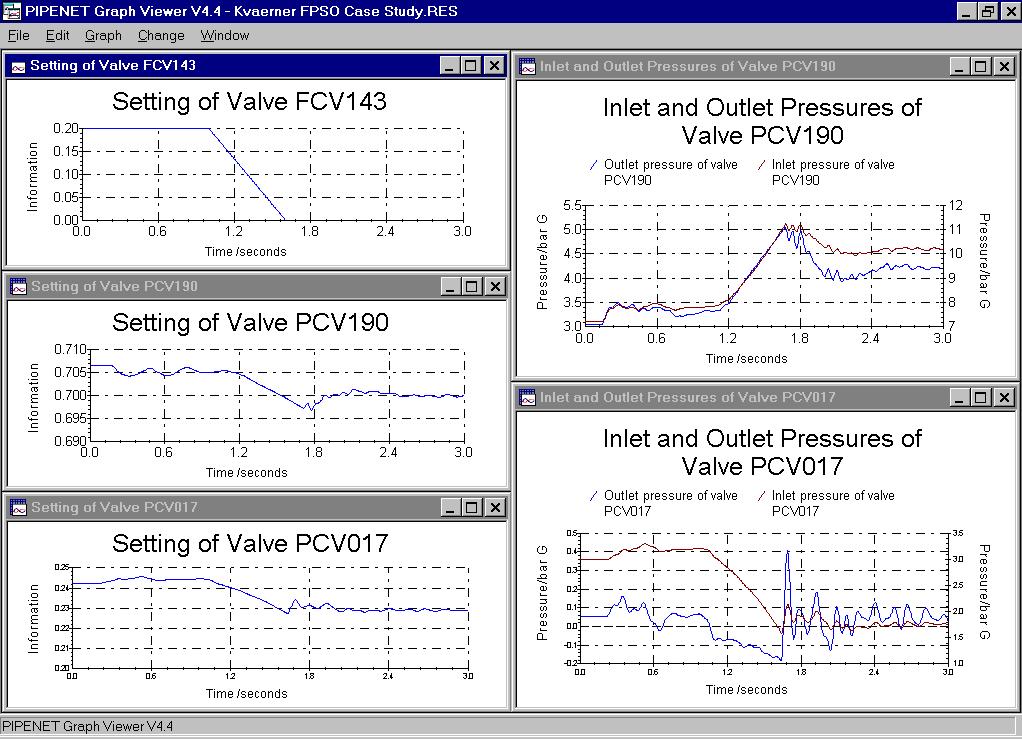
94
JETTY LOADING SYSTEM
 Application Bulletin Process Industry PIPENET Transient Module Case Study JETTY LOADING SYSTEM BACKGROUND The modelling of loading systems is a major application for PIPENET VISION Transient Module. Loading
UNIQUE ADVANTAGES OF PIPENET
 UNIQUE ADVANTAGES OF PIPENET TRANSIENT MODULE Sunrise Systems Limited Section 1: Unique Advantages of the leading hydraulic analysis software engineers prefer to use: PIPENET s schematic design is unique.
PIG MOTION AND DYNAMICS IN COMPLEX GAS NETWORKS. Dr Aidan O Donoghue, Pipeline Research Limited, Glasgow
 PIG MOTION AND DYNAMICS IN COMPLEX GAS NETWORKS Dr Aidan O Donoghue, Pipeline Research Limited, Glasgow A model to examine pigging and inspection of gas networks with multiple pipelines, connections and
Tutorial. BOSfluids. Relief valve
 Tutorial Relief valve The Relief valve tutorial describes the theory and modeling process of a pressure relief valve or safety valve. It covers the algorithm BOSfluids uses to model the valve and a worked
1.2 Example 1: A simple hydraulic system
 Note: It is possible to use more than one fluid in the Hydraulic library. This is important because you can model combined cooling and lubrication systems of a library. The hydraulic library assumes a
Pigging as a Flow Assurance Solution Avoiding Slug Catcher Overflow
 Pigging as a Flow Assurance Solution Avoiding Slug Catcher Overflow Aidan O'Donoghue, Pipeline Research Limited, Glasgow, UK This paper sets out to provide an initial method of assessing the bypass requirements
Journal of Applied Fluid Transients, Vol 1-1, April 2014 (3-1)
") Modeling and Field Verification Study of Air Slam Conditions on kalanit Pipeline System By Yiftach Brunner & Sathish Kumar ir valves are integral part of long water transmission mains and are essential
Modeling and Field Verification Study of Air Slam Conditions on kalanit Pipeline System By Yiftach Brunner & Sathish Kumar ir valves are integral part of long water transmission mains and are essential
CENTER PIVOT EVALUATION AND DESIGN
 CENTER PIVOT EVALUATION AND DESIGN Dale F. Heermann Agricultural Engineer USDA-ARS 2150 Centre Avenue, Building D, Suite 320 Fort Collins, CO 80526 Voice -970-492-7410 Fax - 970-492-7408 Email - dale.heermann@ars.usda.gov
OLGA. The Dynamic Three Phase Flow Simulator. Input. Output. Mass transfer Momentum transfer Energy transfer. 9 Conservation equations
 서유택 Flow Assurance The Dynamic Three Phase Flow Simulator 9 Conservation equations Mass (5) Momentum (3) Energy (1) Mass transfer Momentum transfer Energy transfer Input Boundary and initial conditions
Pipeline Flooding, Dewatering and Venting Dr Aidan O'Donoghue, Pipeline Research Limited, Glasgow, Scotland
 Pipeline Flooding, Dewatering and Venting Dr Aidan O'Donoghue, Pipeline Research Limited, Glasgow, Scotland Abstract Flooding, cleaning, gauging, dewatering and venting of offshore oil and gas pipelines
This portion of the piping tutorial covers control valve sizing, control valves, and the use of nodes.
 Piping Tutorial A piping network represents the flow of fluids through several pieces of equipment. If sufficient variables (flow rate and pressure) are specified on the piping network, CHEMCAD calculates
Fail Operational Controls for an Independent Metering Valve
 Group 14 - System Intergration and Safety Paper 14-3 465 Fail Operational Controls for an Independent Metering Valve Michael Rannow Eaton Corporation, 7945 Wallace Rd., Eden Prairie, MN, 55347, email:
1 PIPESYS Application
 PIPESYS Application 1-1 1 PIPESYS Application 1.1 Gas Condensate Gathering System In this PIPESYS Application, the performance of a small gascondensate gathering system is modelled. Figure 1.1 shows the
OIL AND GAS INDUSTRY
 This case study discusses the sizing of a coalescer filter and demonstrates its fouling life cycle analysis using a Flownex model which implements two new pressure loss components: - A rated pressure loss
VALVE CRITICALITY MODELING
 Casey, R., Boulos, P., Orr, C., and Bros, C. (2008). Valve Criticality Modeling. Eighth Annual ASCE Water Distribution Systems Analysis Symposium, Cincinnati, Ohio, August 27-30, 2006: pp. 1-8. VALVE CRITICALITY
Instruction Manual. Pipe Friction Training Panel
 Instruction Manual HL 102 Pipe Friction Training Panel 100 90 80 70 60 50 40 30 20 10 HL 102 Instruction Manual This manual must be kept by the unit. Before operating the unit: - Read this manual. - All
UNIT 15 WATER HAMMER AND SURGE TANKS
 UNT 15 WATER HAMMER AND SURGE TANKS Structure 15.1 ntroduction Objectives 15.2 Water Hammer 15.2.1 Expression for Rise in Pressure 15.3 Rapid Acceleration of Flow 15.4 Surge Tanks 15.5 Summary 15.6 Keywords
CHEMICAL ENGINEERING LABORATORY CHEG 239W. Control of a Steam-Heated Mixing Tank with a Pneumatic Process Controller
 CHEMICAL ENGINEERING LABORATORY CHEG 239W Control of a Steam-Heated Mixing Tank with a Pneumatic Process Controller Objective The experiment involves tuning a commercial process controller for temperature
Experiment 8: Minor Losses
 Experiment 8: Minor Losses Purpose: To determine the loss factors for flow through a range of pipe fittings including bends, a contraction, an enlargement and a gate-valve. Introduction: Energy losses
CONTROL VALVE TESTING
 The optimal functioning of the Control valve not only exists of sufficient body & seat tightness, but more important, the total "performance" of the valve and its controls! For an accurate and reliable
MITIGATING PIPE AND RISER HYDRAULIC PIPELINE ISSUES WITH THE I-RISER PLUS
 24 TH July 2013 MITIGATING PIPE AND RISER HYDRAULIC PIPELINE ISSUES WITH THE I-RISER PLUS Vern Costelow Business Development Consultant AWMA Water Control Solutions INTRODUCTION Surface irrigation is still
CVEN 311 Fluid Dynamics Fall Semester 2011 Dr. Kelly Brumbelow, Texas A&M University. Final Exam
 CVEN 311 Fluid Dynamics Fall Semester 2011 Dr. Kelly Brumbelow, Texas A&M University Final Exam 8 pages, front & back, not including reference sheets; 21 questions An excerpt from the NCEES Fundamentals
INTEGRITY, SAFETY AND EFFICIENCY IN LNG TRANSFER IMPACT OF EMERGENCY SHUTDOWN AND RELEASE OPERATIONS
 INTEGRITY, SAFETY AND EFFICIENCY IN LNG TRANSFER IMPACT OF EMERGENCY SHUTDOWN AND RELEASE OPERATIONS Evert van Bokhorst Frank Driessen Erik Nennie David Remans Jan Smeulers TNO Technical Sciences Delft,
Tube rupture in a natural gas heater
 Tube rupture in a natural gas heater Dynamic simulation supports the use of a pressure safety valve over a rupture disk in the event of a tube rupture HARRY Z HA and PATRICK STANG Fluor Canada Ltd A fast
Transient Analyses In Relief Systems
 Transient Analyses In Relief Systems Dirk Deboer, Brady Haneman and Quoc-Khanh Tran Kaiser Engineers Pty Ltd ABSTRACT Analyses of pressure relief systems are concerned with transient process disturbances
2600T Series Pressure Transmitters Plugged Impulse Line Detection Diagnostic. Pressure Measurement Engineered solutions for all applications
 Application Description AG/266PILD-EN Rev. C 2600T Series Pressure Transmitters Plugged Impulse Line Detection Diagnostic Pressure Measurement Engineered solutions for all applications Increase plant productivity
Best Practice RBI Technology Process by SVT-PP SIMTECH
 Best Practice RBI Technology Process by SVT-PP SIMTECH We define the best practice in RBI as a proactive technology process which is used to formally and reliably optimise the inspection efforts for each
Courses of Instruction: Controlling and Monitoring of Pipelines
 Courses of Instruction: Controlling and Monitoring of Pipelines Date December 2010 Dr. Peter Eschenbacher Partner Angergraben 4 85250 Altomünster Germany Tel. +49-(0)8254 / 99 69 57 Fax +49-(0)8254 / 99
RESIDENTIAL WATER DISTRIBUTION
 RESIDENTIAL WATER DISTRIBUTION This case study demonstrates the steady-state simulation of the fresh water (drinking water) reticulation system in a small village. WATER RETICULATION Page1 WATER RETICULATION
AKTA pure 25 New Owner s Intro
 AKTA pure 25 New Owner s Intro The exercise below will give a quick demonstration of how easy and intuitive the AKTA pure 25 will be for you in demonstrating downstream processing to your students. Steps
Cover Page for Lab Report Group Portion. Head Losses in Pipes
 Cover Page for Lab Report Group Portion Head Losses in Pipes Prepared by Professor J. M. Cimbala, Penn State University Latest revision: 02 February 2012 Name 1: Name 2: Name 3: [Name 4: ] Date: Section
Modeling a Pressure Safety Valve
 Modeling a Pressure Safety Valve Pressure Safety Valves (PSV), Pressure Relief Valves (PRV), and other pressure relieving devices offer protection against overpressure in many types of hydraulic systems.
PRESSURE SURGES IN PIPELINES
 CHAPTER 4 PRESSURE SURGES IN PIPELINES 4.1 FEATURES OF PRESSURE SURGE In the past, water engineers were facing problems with repeated pipe bursts, failing seals etc. They termed the cause of failure as
Inprocess Operator Training Programme
 2016 Inprocess Operator Training Programme ABSORPTION COLUMN These exercises are intended to provide an understanding of absorption columns and the fundamental principles they use to eliminate pollutants
Dynamic Simulation for T-9 Storage Tank (Holding Case)
") Dynamic Simulation for T-9 Storage Tank (Holding Case) CASE 1: 19,642 Kg/Hr (Holding: 52 o C), No Liquid Draw Workshop Description Estimation of vapor flow rate coming out from the T-9 tank for holding
Dynamic Simulation for T-9 Storage Tank (Holding Case) CASE 1: 19,642 Kg/Hr (Holding: 52 o C), No Liquid Draw Workshop Description Estimation of vapor flow rate coming out from the T-9 tank for holding
Workshop 1: Bubbly Flow in a Rectangular Bubble Column. Multiphase Flow Modeling In ANSYS CFX Release ANSYS, Inc. WS1-1 Release 14.
 Workshop 1: Bubbly Flow in a Rectangular Bubble Column 14. 5 Release Multiphase Flow Modeling In ANSYS CFX 2013 ANSYS, Inc. WS1-1 Release 14.5 Introduction This workshop models the dispersion of air bubbles
σ = force / surface area force act upon In the image above, the surface area would be (Face height) * (Face width).
 * (Face width).") Aortic Root Inflation Introduction You have already learned about the mechanical properties of materials in the cantilever beam experiment. In that experiment you used bending forces to determine the Young
Aortic Root Inflation Introduction You have already learned about the mechanical properties of materials in the cantilever beam experiment. In that experiment you used bending forces to determine the Young
44 (0) E:
 E:") FluidFlow Relief Valve Sizing Handbook Flite Software 2016 Flite Software N.I. Ltd, Block E, Balliniska Business Park, Springtown Rd, Derry, BT48 0LY, N. Ireland. T: 44 (0) 2871 279227 E: sales@fluidflowinfo.com
FluidFlow Relief Valve Sizing Handbook Flite Software 2016 Flite Software N.I. Ltd, Block E, Balliniska Business Park, Springtown Rd, Derry, BT48 0LY, N. Ireland. T: 44 (0) 2871 279227 E: sales@fluidflowinfo.com
SHELL FLAGS INSPECTION CASE STUDY
 SHELL FLAGS INSPECTION CASE STUDY J. Nonemaker, Solution Engineer, ROSEN T. Steinvoorte, Business Development, ROSEN R. Subramanian, Pipelines & Subsea Technical Support Engineer, Shell U.K. Limited Introduction
Tirpur Area Water Supply Project A Report on Transient Modeling Study
 y February 2008 1 of 81 y INTRODUCTION: The report presents results from a transient modeling study conducted on the clear water transmission main of Tirpur Areas Water Supply Project, Tamilnadu, India.
The API states the following about tube rupture for a shell-and-tube heat exchangers:
 Tutorial This tutorial describes the theory and modeling process of a tube rupture event using the special element type Rupture element in BOSfluids. It covers the algorithm BOSfluids uses to model the
Ammonia Synthesis with Aspen Plus V8.0
 Ammonia Synthesis with Aspen Plus V8.0 Part 2 Closed Loop Simulation of Ammonia Synthesis 1. Lesson Objectives Review Aspen Plus convergence methods Build upon the open loop Ammonia Synthesis process simulation
Characterizers for control loops
 Characterizers for control loops By: F. G. Shinskey (May 1999) Introduction Commercial controllers such as the PID series (proportional, integral, derivative, and their combinations) are linear devices
OCTOBER 2017 ISSUE Page 1 of 7
 Field testing is performed on fully assembled pipelines for the purpose of determining pipeline acceptability. Following visual acceptance of joints and pipeline components, pressure pipelines in their
LOW PRESSURE EFFUSION OF GASES revised by Igor Bolotin 03/05/12
 LOW PRESSURE EFFUSION OF GASES revised by Igor Bolotin 03/05/ This experiment will introduce you to the kinetic properties of low-pressure gases. You will make observations on the rates with which selected
RIGID RISERS FOR TANKER FPSOs
 RIGID RISERS FOR TANKER FPSOs Stephen A. Hatton 2H Offshore Engineering Ltd. SUMMARY Recent development work on the subject of dynamic rigid (steel pipe) risers demonstrates that their scope of application
Drilling Efficiency Utilizing Coriolis Flow Technology
 Session 12: Drilling Efficiency Utilizing Coriolis Flow Technology Clement Cabanayan Emerson Process Management Abstract Continuous, accurate and reliable measurement of drilling fluid volumes and densities
Technical Standards and Legislation: Risk Based Inspection. Presenter: Pierre Swart
 Technical Standards and Legislation: Risk Based Inspection Presenter: Pierre Swart Agenda Change in Legislation. Where RBI fits in. Application to implement RBI. RBI concepts. Elements of an RBI analysis.
VISIMIX TURBULENT. HEAT TRANSFER PROCESS IN A SEMIBATCH REACTOR
 VISIMIX TURBULENT. HEAT TRANSFER PROCESS IN A SEMIBATCH REACTOR WITH HEAT CONSUMPTION. The example below was specially designed to demonstrate VisiMix capabilities in simulation of heat transfer processes
UNITY 2 TM. Air Server Series 2 Operators Manual. Version 1.0. February 2008
 UNITY 2 TM Air Server Series 2 Operators Manual Version 1.0 February 2008 1. Introduction to the Air Server Accessory for UNITY 2...2 1.1. Summary of Operation...2 2. Developing a UNITY 2-Air Server method
Exercise 3. Power Versus Wind Speed EXERCISE OBJECTIVE DISCUSSION OUTLINE. Air density DISCUSSION
 Exercise 3 Power Versus Wind Speed EXERCISE OBJECTIVE When you have completed this exercise, you will know how to calculate the power contained in the wind, and how wind power varies with wind speed. You
The Protection of Silos From Over. Pressurisation During Filling
 SHAPA Technical Bulletin No.11 The Protection of Silos From Over Pressurisation During Filling Page 1 of 8 August 2005 The Protection of Silos From Over Pressurisation During Filling By James Duggleby,
A review of best practices for Selection, Installation, Operation and Maintenance of Gas meters for Flare Applications used for Managing facility
 A review of best practices for Selection, Installation, Operation and Maintenance of Gas meters for Flare Applications used for Managing facility mass balance and compliance 1. What, When and Why? 2. Flare
Vibration and Pulsation Analysis and Solutions
 1 Vibration and Pulsation Analysis and Solutions Brian Howes, M.Sc., P.Eng. Beta Machinery Analysis Ltd. Problems created by excessive vibration in machinery can have serious economic impact. Frequently
Cover Page for Lab Report Group Portion. Pump Performance
 Cover Page for Lab Report Group Portion Pump Performance Prepared by Professor J. M. Cimbala, Penn State University Latest revision: 02 March 2012 Name 1: Name 2: Name 3: [Name 4: ] Date: Section number:
LABORATORY EXERCISE 1 CONTROL VALVE CHARACTERISTICS
 Date: Name: LABORATORY EXERCISE 1 CONTROL VALVE CHARACTERISTICS OBJECTIVE: To demonstrate the relation between valve stem position and the fluid flow through a control valve, for both linear and equal
FIRE PROTECTION. In fact, hydraulic modeling allows for infinite what if scenarios including:
 By Phil Smith, Project Manager and Chen-Hsiang Su, PE, Senior Consultant, Lincolnshire, IL, JENSEN HUGHES A hydraulic model is a computer program configured to simulate flows for a hydraulic system. The
Lab 4: Root Locus Based Control Design
 Lab 4: Root Locus Based Control Design References: Franklin, Powell and Emami-Naeini. Feedback Control of Dynamic Systems, 3 rd ed. Addison-Wesley, Massachusetts: 1994. Ogata, Katsuhiko. Modern Control
Author s Name Name of the Paper Session. Positioning Committee. Marine Technology Society. DYNAMIC POSITIONING CONFERENCE September 18-19, 2001
 Author s Name Name of the Paper Session PDynamic Positioning Committee Marine Technology Society DYNAMIC POSITIONING CONFERENCE September 18-19, 2001 POWER PLANT SESSION A New Concept for Fuel Tight DP
The benefits of the extended diagnostics feature. Compact, well-proven, and flexible
 ABB MEASUREMENT & ANALYTICS TECHNICAL INFORMATION PositionMaster EDP300 Extended Diagnostics Compact, well-proven, and flexible The benefits of the extended diagnostics feature The PositionMaster EDP300
SUMMARY PROBLEMS CAUSED BY BACKFLOW IN PIPE SYSTEMS.
 Page 1 of 11 SUMMARY There are many problems derived from a reverse flow in a piping system. A solution presented in this paper is the WaStop inline check valve. The paper aims to explain some of the important
The University of Hong Kong Department of Physics Experimental Physics Laboratory
 The University of Hong Kong Department of Physics Experimental Physics Laboratory PHYS2260 Heat and Waves 2260-1 LABORATORY MANUAL Experiment 1: Adiabatic Gas Law Part A. Ideal Gas Law Equipment Required:
LOW PRESSURE EFFUSION OF GASES adapted by Luke Hanley and Mike Trenary
 ADH 1/7/014 LOW PRESSURE EFFUSION OF GASES adapted by Luke Hanley and Mike Trenary This experiment will introduce you to the kinetic properties of low-pressure gases. You will make observations on the
CASE STUDY. Elvington To Brayton Barff Air valve replacement Program
 CASE STUDY Elvington To Brayton Barff Air valve replacement Program Vent-O-Mat Anti-Shock Air valves have helped Yorkshire Water reduce maintenance costs, reduces surge and improve flows in their trunk
Heat Pump Connections and Interior Piping
 Job Sheet 3 Heat Pump Connections and Interior Piping OBJECTIVES In this job sheet, you will observe how the presence of air in the ground loop affects the geothermal heat pump performance. You will also
Using the CONVAL software for the petrochemical plant control valves checking. Case study
 Using the CONVAL software for the petrochemical plant control valves checking. Case study C. Patrascioiu, G. Stamatescu, C. Lazar Abstract In the paper there are presented the researches into field of
SPE The paper gives a brief description and the experience gained with WRIPS applied to water injection wells. The main
 SPE 102831 Online Water-Injection Optimization and Prevention of Reservoir Damage Bjørn Øyvind Bringedal, Svein Arne Morud, Nicolas Alexander Hall, ABB; Gary Huseman, Shell Copyright 2006, Society of Petroleum
UNIVERSITY OF WATERLOO
 UNIVERSITY OF WATERLOO Department of Chemical Engineering ChE 524 Process Control Laboratory Instruction Manual January, 2001 Revised: May, 2009 1 Experiment # 2 - Double Pipe Heat Exchanger Experimental
Module No. # 01 Lecture No. # 6.2 HAZOP (continued)
") Health, Safety and Environmental Management in Petroleum and Offshore Engineering Prof. Srinivasan Chandrasekaran Department of Ocean Engineering Indian Institute Of Technology, Madras Module No. # 01
Health, Safety and Environmental Management in Petroleum and Offshore Engineering Prof. Srinivasan Chandrasekaran Department of Ocean Engineering Indian Institute Of Technology, Madras Module No. # 01
BLOCKAGE LOCATION THE PULSE METHOD
 BLOCKAGE LOCATION THE PULSE METHOD Presented by John Pitchford Pitchford In-Line Author James Pitchford ABSTRACT Pipeline blockages can result from a number of different mechanisms: wax or solid hydrates
Float Valve Function and Design Considerations
 Float Operated Inlet Control Valves Their Ins and Outs Ian McCrone Chairman, Association of Tank and Cistern Manufacturers How often are you confronted with problems associated with Float Operated Level
APPLYING VARIABLE SPEED PRESSURE LIMITING CONTROL DRIVER FIRE PUMPS. SEC Project No
 APPLYING VARIABLE SPEED PRESSURE LIMITING CONTROL DRIVER FIRE PUMPS SEC Project No. 1803007-000 November 20, 2006 TABLE OF CONTENTS I. ABSTRACT...1 II. INTRODUCTION...1 III. HISTORY...2 IV. VARIABLE SPEED
Every things under control High-Integrity Pressure Protection System (HIPPS)
") Every things under control www.adico.co info@adico.co Table Of Contents 1. Introduction... 2 2. Standards... 3 3. HIPPS vs Emergency Shut Down... 4 4. Safety Requirement Specification... 4 5. Device Integrity
Every things under control www.adico.co info@adico.co Table Of Contents 1. Introduction... 2 2. Standards... 3 3. HIPPS vs Emergency Shut Down... 4 4. Safety Requirement Specification... 4 5. Device Integrity
2 FUSION FITTINGS FOR USE WITH POLYETHYLENE PRESSURE PIPES DESIGN FOR DYNAMIC STRESSES
 Industry Guidelines Part 2 FUSION FITTINGS FOR USE WITH POLYETHYLENE PRESSURE PIPES DESIGN FOR DYNAMIC STRESSES ISSUE 5.1 Ref: POP10B 15 MAR 2010 Disclaimer In formulating this guideline PIPA has relied
NORDCALC Introduction... 2 Registration... 2 Flow Calculations tab Torque Calculation & Actuator Mounting Data tab... 21
 NORDCALC User Guide Table of Contents NORDCALC Introduction... 2 Registration... 2 Flow Calculations tab... 5 Calculating the gas flow rate for gaseous medium... 6 Calculating the pressure drop for gaseous
Modelling of the Separated Geothermal Water Flow between Te Mihi flash plants
 Proceedings World Geothermal Congress 2015 Melbourne, Australia, 19-25 April 2015 Modelling of the Separated Geothermal Water Flow between Te Mihi flash plants Kevin Koorey, Kim Harwood and Norman Lawgun
International Journal of Technical Research and Applications e-issn: , Volume 4, Issue 3 (May-June, 2016), PP.
, PP.") DESIGN AND ANALYSIS OF FEED CHECK VALVE AS CONTROL VALVE USING CFD SOFTWARE R.Nikhil M.Tech Student Industrial & Production Engineering National Institute of Engineering Mysuru, Karnataka, India -570008
DESIGN AND ANALYSIS OF FEED CHECK VALVE AS CONTROL VALVE USING CFD SOFTWARE R.Nikhil M.Tech Student Industrial & Production Engineering National Institute of Engineering Mysuru, Karnataka, India -570008
Unsteady Flow in Pipes
 The Islamic University of Gaza Faculty of Engineering Civil Engineering Department Hydraulics - ECIV 3322 Chapter 4 Unsteady Flow in Pipes Water Hammer Phenomenon in pipelines A sudden change of flow rate
Risks Associated with Caissons on Ageing Offshore Facilities
 Risks Associated with Caissons on Ageing Offshore Facilities D. Michael Johnson, DNV GL, Peter Joyce, BG Group, Sumeet Pabby, BG Group, Innes Lawtie, BG Group. Neil Arthur, BG Group, Paul Murray, DNV GL.
AC : MEASUREMENT OF HYDROGEN IN HELIUM FLOW
 AC 2010-2145: MEASUREMENT OF HYDROGEN IN HELIUM FLOW Randy Buchanan, University of Southern Mississippi Christopher Winstead, University of Southern Mississippi Anton Netchaev, University of Southern Mississippi
The Discussion of this exercise covers the following points:
 Exercise 5-3 Wet Reference Leg EXERCISE OBJECTIVE Learn to measure the level in a vessel using a wet reference leg. DISCUSSION OUTLINE The Discussion of this exercise covers the following points: Measuring
OIL SUPPLY SYSTEMS ABOVE 45kW OUTPUT 4.1 Oil Supply
 OIL SUPPLY SYSTEMS ABOVE 45kW OUTPUT 4.1 Oil Supply 4.1.1 General The primary function of a system for handling fuel oil is to transfer oil from the storage tank to the oil burner at specified conditions
Fluid Flow. Link. Flow» P 1 P 2 Figure 1. Flow Model
 Fluid Flow Equipment: Water reservoir, output tubes of various dimensions (length, diameter), beaker, electronic scale for each table. Computer and Logger Pro software. Lots of ice.temperature probe on
SIDRA INTERSECTION 6.1 UPDATE HISTORY
 Akcelik & Associates Pty Ltd PO Box 1075G, Greythorn, Vic 3104 AUSTRALIA ABN 79 088 889 687 For all technical support, sales support and general enquiries: support.sidrasolutions.com SIDRA INTERSECTION
Hydraulic and Economic Analysis of Real Time Control
 Hydraulic and Economic Analysis of Real Time Control Tom Walski 1, Enrico Creaco 2 1 Bentley Systems, Incorporated, 3 Brian s Place, Nanticoke, PA, USA 2 Dipartimento di Ingegneria Civile ed Architettura,
INSTRUMENT INSTRUMENTAL ERROR (of full scale) INSTRUMENTAL RESOLUTION. Tutorial simulation. Tutorial simulation
 INSTRUMENTAL RESOLUTION. Tutorial simulation. Tutorial simulation") Lab 1 Standing Waves on a String Learning Goals: To distinguish between traveling and standing waves To recognize how the wavelength of a standing wave is measured To recognize the necessary conditions
Lab 1 Standing Waves on a String Learning Goals: To distinguish between traveling and standing waves To recognize how the wavelength of a standing wave is measured To recognize the necessary conditions
Gas Injection for Hydrodynamic Slug Control
 Proceedings of the IFAC Workshop on Automatic Control in Offshore Oil and Gas Production, Norwegian University of Science and Technology, Trondheim, Norway, May 3 - June, ThB.4 Gas Injection for Hydrodynamic
Multiple Pressure Booster Systems With Variable Speed Controller Type BL
 Multiple Pressure Booster Systems With Variable Speed Controller Type BL General Characteristics - Single or multistage pumps - Horizontal or vertical mounting - Total head 30m ~ 250m - Material construction:
Gerald D. Anderson. Education Technical Specialist
 Gerald D. Anderson Education Technical Specialist The factors which influence selection of equipment for a liquid level control loop interact significantly. Analyses of these factors and their interactions
Selecting Maintenance Tactics Section 4
 ARE 24 Facilities Maintenance Management Prepared By: KAMAL A. BOGES # 2321 November 2 nd, 2003 Selecting Maintenance Tactics Section 4 Uptime Strategies for Excellence in Maintenance Management By: John
LNG TANDEM OFFLOADING A KEY ENABLING TECHNOLOGY TO MAKE LNG PRODUCTION OFFSHORE HAPPEN
 LNG TANDEM OFFLOADING A KEY ENABLING TECHNOLOGY TO MAKE LNG PRODUCTION OFFSHORE HAPPEN Fabrice Dumortier 1, Jean-Pierre Queau 1, Jean-Robert Fournier 2 1. SBM Offshore 2. SBM Offshore Keywords: 1. LNG;
FLUID POWER FLUID POWER EQUIPMENT TUTORIAL ACCUMULATORS. This work covers part of outcome 2 of the Edexcel standard module:
 FLUID POWER FLUID POWER EQUIPMENT TUTORIAL ACCUMULATORS This work covers part of outcome 2 of the Edexcel standard module: UNIT 21746P APPLIED PNEUMATICS AND HYDRAULICS The material needed for outcome
ISO INTERNATIONAL STANDARD
 INTERNATIONAL STANDARD ISO 10770-3 First edition 2007-10-15 Hydraulic fluid power Electrically modulated hydraulic control valves Part 3: Test methods for pressure control valves Transmissions hydrauliques
INHERENTLY SAFER DESIGN CASE STUDY OF RAPID BLOW DOWN ON OFFSHORE PLATFORM
 INHERENTLY SAFER DESIGN CASE STUDY OF RAPID BLOW DOWN ON OFFSHORE PLATFORM Volton Edwards bptt Angus Lyon DNV Energy Alastair Bird DNV Energy INTRODUCTION A term now in common usage within the oil & gas
Modelling of Pressurised Pipes within InfoWorks ICM and CS
 Modelling of Pressurised Pipes within InfoWorks ICM and CS 1. Introduction Correctly modelling pressurised pipes, variously described as forcemains or rising mains, can be one of the more difficult aspects
How to Optimize the Disposal System With Staggered Analysis Using BLOWDOWN Technology. Jump Start Guide
 How to Optimize the Disposal System With Staggered Analysis Using BLOWDOWN Technology Jump Start Guide Problem Statement In this guide, you will be introduced to the tools in BLOWDOWN that can be used
Control Strategies for operation of pitch regulated turbines above cut-out wind speeds
 Control Strategies for operation of pitch regulated turbines above cut-out wind speeds Helen Markou 1 Denmark and Torben J. Larsen, Risø-DTU, P.O.box 49, DK-4000 Roskilde, Abstract The importance of continuing
WATER HYDRAULIC HIGH SPEED SOLENOID VALVE AND ITS APPLICATION
 WATER HYDRAULIC HIGH SPEED SOLENOID VALVE AND ITS APPLICATION Akihito MITSUHATA *, Canghai LIU *, Ato KITAGAWA * and Masato KAWASHIMA ** * Department of Mechanical and Control Engineering, Graduate school
John Gurden, J P Kenny Ltd Onshore Pipeline and the Landfall Valve Installation (LVI) Design. Knowledge of the Corrib Onshore Pipeline Project
 Design. Knowledge of the Corrib Onshore Pipeline Project") STATEMENT OF EVIDENCE ABP Ref. No: PL16.GA0004 John Gurden, J P Kenny Ltd Onshore Pipeline and the Landfall Valve Installation (LVI) Design Qualifications and Experience 1. My name is John Gurden and I
STATEMENT OF EVIDENCE ABP Ref. No: PL16.GA0004 John Gurden, J P Kenny Ltd Onshore Pipeline and the Landfall Valve Installation (LVI) Design Qualifications and Experience 1. My name is John Gurden and I
Boyle s Law: Pressure-Volume Relationship in Gases
 Boyle s Law: Pressure-Volume Relationship in Gases The primary objective of this experiment is to determine the relationship between the pressure and volume of a confined gas. The gas we will use is air,