Simple Dew Point Control Aspen Plus v10
|
|
|
- Rosamund Nash
- 6 years ago
- Views:
Transcription
1 Steps are presented to set up a simulation in Aspen Plus v8.8 to model a simple dew point control system consisting of: Gas chiller Flash separator Liquid stabilizer with gas recycle & compression Product gas compression Simple propane refrigeration loop When the simulation is set up the overall PFD should look like the figure to the right. Simple Dew Point Control Aspen Plus v10 Basis A gas plant is processing 100 MMscfd (dry basis) to produce a spec pipeline gas as well as a pipeline raw mix liquid product (Y Grade). The following are known conditions for the feedstock and specification for the products: The composition of the feed gas is shown in the following Component Mol% table. The gas enters the plant at 400 psia & 120 F. The gas is nearly saturated with water at the inlet conditions, 48 lb water per MMscf dry gas. The produced pipeline gas should have a gross heating value between 905 to 1050 Btu/scf 1 & a hydrocarbon dew point no higher than 15 F. The produced pipeline gas should be delivered to the pipeline at 1000 psia and no higher than 120 F. The produced liquids shall be exported via pipeline & stabilized to have a TVP (true vapor 100 F no greater than 103 psia. N CO C C C i C n C i C n C n C n C n C n C A propane refrigeration loop will be used to provide the chilling duty. The condenser will operate at 120 F. The minimum approach temperature within the chiller will be 10 F. Air coolers will be used to cool gases & liquids to 120 F. Create new simulation file When running under Windows 10 you can start the program from Start, the all programs list, Aspen Plus, Aspen Plus V10. When the program opens choose the new button. there are several templates 1 If the gross heating value spec cannot be achieved set the chilled separator to the lowest reasonable temperature when using a simple propane chilling loop, 30 F. Rev January 9, 2018


2 that can be chosen. Select the Gas Processing option in the left hand column & chose the Gas Processing with English Units template. Press Create. Save as you go One of the things you ll want to do is to save your files as you go. The first time you go to the Save As option you ll have several formats from which to choose. There are advantages to save as the Aspen Plus Backup (BKP) format the files tend to be smaller & less likely to become corrupted. For this problem let s use the name Simple Dew Point Control V10. Define the Components & the Property Models Specify components, fluid property packages, & crude oil assays The first step is to add a set of pure chemical species to represent the gas & water phases. When you open a new file the default screen should be the Component Specifications form. (If not, press Rev January 9, 2018
 W will want to add the following pure components: water, nitrogen, carbon dioxide, methane, ethane, propane, i butane, n butane, i pentane, n pentane, n")

3 the Specifications item under Components in the left hand column.) W will want to add the following pure components: water, nitrogen, carbon dioxide, methane, ethane, propane, i butane, n butane, i pentane, n pentane, n hexane, n heptane, n octane, & n nonane. One of the direct ways to do this is to press Find & use the search form to find the desired components. The following forms show a search for H2O; key phrases can be used with the Equals or Contains options to find all components. For each succeeding compound you will be asked to replace one of the compounds or add to the list; choose add to the list. Rev January 9, 2018

4 When you start adding the other components you have an extra question to answer, whether to add or replace the current component. You will probably want to choose Add until you ve added all of your components. There are various tricks for finding groups of compounds. For example, by searching for n Alkanes that contain ethane you can get the light hydrocarbons. You can select & add all as a group. Rev January 9, 2018


5 After finding all of the components you should have a list that looks similar to the following form. Rev January 9, 2018

6 Aspen Plus will retrieve information about each component & also create a Component ID for this simulation. You are free to change these IDs to match your personal desires. For example, you can change the ID for METHA 01 to C1 by doubling clicking on that text item; after changing the text value & pressing enter Aspen Plus will verify that you want to Rename the component & replace that component with something else. This can be done for all of the components to create (IMHO) more reasonable IDs. Rev January 9, 2018

7 Another issue is the order that the components may have been extracted. I have a personal preference for a list in the order of water, light gas components, & then the hydrocarbons in increasing carbon number order. This is not the current order. You can change the order by pressing the Reorder button & then using the up & down arrows to put components in your preferred order. The next step would normally be to pick a fluid property package. However, when we chose the Gas Processing option when we created the simulation the Peng Robinson equation of state method was chosen as the default. We can see this by selecting Methods & Specifications in the left hand column. Notice that the Base Method is PENG ROB. We will keep this default selection. Rev January 9, 2018

8 There may still be items to be addressed before we can enter the Simulation section (you can tell this if there is a symbol in the left hand column). To find out what needs to be done click the button. You may get a form that allows us to modify values for the Peng Robinson binary interaction coefficients. If you get this, do not change any of the values. Rev January 9, 2018

. An Heater, CHILLER A Flash3 separator, COLDSEP.")
9 Now when you press the (Next) button the program should show you that you can go on to the next step. Select Go to the Simulation environment & press OK. Set up & Solve the Flowsheet Gas Chilling & Separation When you activate the simulation environment & you ll see a blank flowsheet. We will want to create a feed stream & attach it to a Heater. The outlet will be attached to a three phase flash separator. Ensure that the model Palette is visible. If it is not, press the View tab & click Model Palette. A shortcut key is to press F10. Place the following units on the flowsheet: A Heater, COMBINE. (You may want to choose one of the squares for its icon instead of a heat exchanger). An Heater, CHILLER A Flash3 separator, COLDSEP. As shown in the BFD above, connect the units with mass streams DRYFEED, FEEDWATR, WETFEED, CHILLED, COLDVAP, COLDLIQ, & COLDWATR as well as the Heat stream Q CHILLR. (Remember that stream names can only be 8 characters in length & will always be capitalized.) Rev January 9, 2018
; you do not need to make sure the numbers add to 1, the program will normalize as appropriate.")
. Enter the pressure & the temperature.")
10 Double click on the DRYFEED stream to open up the entry forms to specify composition & conditions. Ensure that the Flash Type is Temperature & Pressure. Enter the flowrate with a Mole basis & use the MMscfd units. Use Mole frac for the composition (dry basis, i.e., no water); you do not need to make sure the numbers add to 1, the program will normalize as appropriate. We want to do the same thing for the water portion of the feed represented by the stream FEEDWATR. Double click on the FEEDWATR stream to open up the entry forms for this stream. Enter 4,800 lb/day using the Mass basis (to represent the 48 lb/mmscf water content). Enter the pressure & the temperature. Since this is pure water you can specify the composition either using Mass Frac or Mole Frac. Rev January 9, 2018

.")

11 We mix together the separate DRYFEED & FEEDWATR streams to define the wet feed to the gas plant. Normally we would do this with a Mixer operation, but instead we re going to do it with a Heater to be able to specify the actual temperature of the wet feed. Double click on COMBINE to open the input form. Specify the 120 F outlet Temperature. Specify the Pressure as 400 psia (we could have specified a zero to denote a zero pressure drop but specifying the actual pressure gives us a single point of control for the inlet pressure). Pull down the Valid phases list & choose Vapor Liquid FreeWater. We now want to model the gas side of the chiller. We will ultimately use a different operation to model both the process & coolant sides of the exchanger, but here we ll just model the process feed side with a Heater. Double click on CHILLER. For now specify the Pressure as 0 psia (to signify a zero pressure drop). Pull down the Valid phases list & choose Vapor Liquid FreeWater. For now let s specify the outlet Temperature as 15 F (the spec value for the dew point of the produced gas in the pipeline). Finally, let s specify the operation for the cold separator. Double click on COLDSEP. Set the Flash Type as Duty & Pressure. Specify the Pressure as 0 psia (to signify a zero pressure drop) & the Duty as 0 MMBtu/hr (to signify adiabatic operation). Pressing Next shows that all of the required specifications have been made. Press OK to run the simulation. A tab for the Control Panel should open up & indicate that the simulation has run successfully. (Notice that there is a warning concerning the number of phases in the COMBINE block; since no free water should form from this operation this can be ignored.) Rev January 9, 2018


12 What are some of the results? We can get an overview by posting summary conditions on the flowsheet. Click on Stream Results in the Modify tab of the ribbon. Select Temperature, Pressure, Mass flow rate, & Heat/Duty. Press OK. Now these numbers are posted on the flowsheet. Rev January 9, 2018


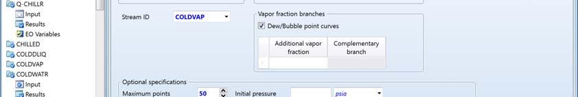
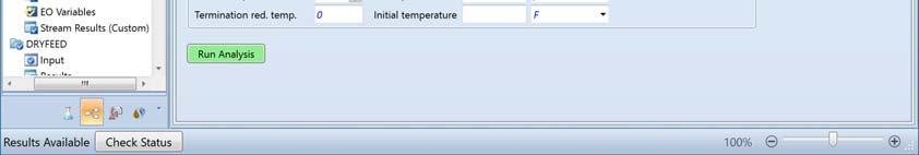
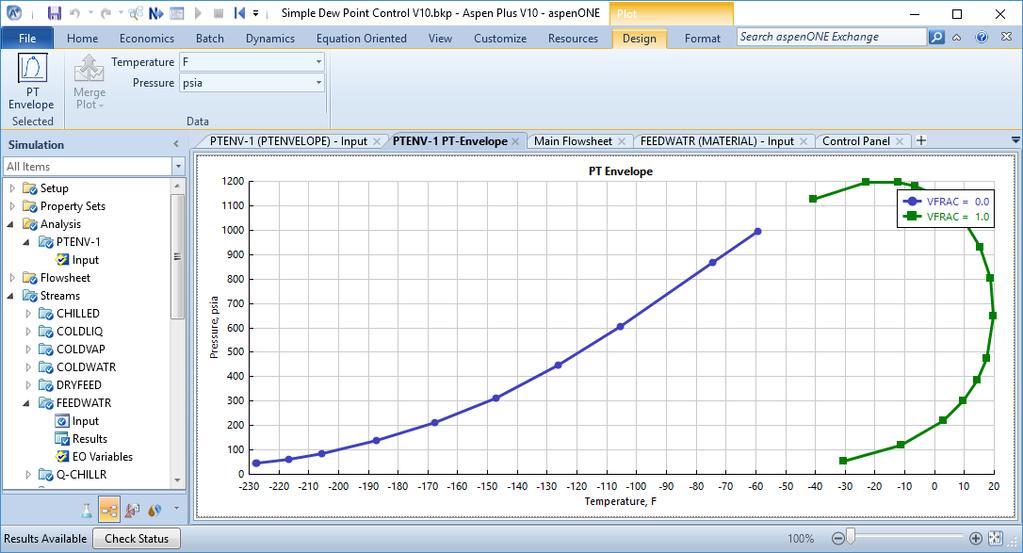
13 Notice that all values are calculated for the streams out of COLDSEP are at 15 F. This means that the vapor out of the separator, COLDVAP, is at its dew point at 15 F. This makes the pipeline s dew point spec, right? No, not really. But how would we know this? We can look at the phase envelope for COLDVAP to determine if the vapor will have a minimum dew point temperature at all pressures it is likely to experience in the pipeline. Click on stream COLDVAP; in the ribbon under the Home tab select the pulldown list Stream Analysis & select PT Envelope. Make sure the Stream ID is COLDVAP. Press Run Analysis. You will see a phase diagram showing the bubble point & dew point curves; from the diagram you can see that the cricondentherm is about 20 F. Select the Results for PTENV 1 in the left hand column; from the table of values you can see that the highest temperature (essentially the cricondentherm) is 19.8 F. This occurs at 647 psia. Rev January 9, 2018


14 Rev January 9, 2018


15 The pressure at which the cricondentherm occurs is very much in the possible range of pipeline operating pressures. Since the gas in the pipeline will experience pressures lower than the inlet s 1000 psia, it is appropriate to use the cricondentherm as the controlling value for this spec. And since the temperature is 20 F, this gas does not make this spec. For now we ll use trial and error to determine an appropriate temperature for the cold separator. Note that if we specify the temperature out of CHILLER as 9 F we get a cricondentherm of COLDVAP of just under 15 F. Have we met the heating value spec? We can determine this by making use of the built in net & gross heating values & adding to the stream report. Expand the Setup item in the left hand tree structure of the Simulation items. Under Property Sets create a New set called HEATVALS. Edit that property set & add the properties QVALGRS & QVALNET. (For reasons to be noted later, make sure that QVALGRS is the first in the list.) Rev January 9, 2018


16 Now we can rerun the simulation & look for the Results for COLDVAP. Go to the bottom of the stream report & click on <add properties>. Toward the bottom of the list click on both HEATVALS properties & click OK. At the bottom of the Edit Stream Property Template form press OK. Now when you look at the stream report for COLDVAP you ll see the gross & net heating values. Rev January 9, 2018
17 The bad news is that even though the net & gross heating values are calculated & reported at the bottom of the list these values are in mass units, not the scf molar units that we really want. We ll have to do some unit conversions using the Mass flow & Mole flow values: HHV Btu lb hr lb hr day MMscf 6 scf day MMscf Btu scf This value is too high & will require more heavy hydrocarbons be removed. But before we focus on this let s add additional processing to stabilize the liquid formed (since this will involve recycling back the evolved gas). Liquid Stabilization Determination of liquid s TVP value The next step is to determine if the produced liquid will make the TVP spec of 103 psia. Let s add a Heater TVPCALC on to COLDLIQ & use it to determine the bubble point pressure at 100 F. Set the Vapor fraction to 0 (to correspond to a liquid fraction of exactly 1). Rev January 9, 2018


18 Run the simulation. There are various ways to check for the calculated vapor pressure; let s look at the stream Results for LIQUID. This shows that the TVP is 654 psia, much higher than the desired 103 psia. We can look at the composition to see the problem the amount of methane is roughly the same as the ethane & propane. This is much too high for a Y grade NGL liquid mix. How can we see the mole fractions? These are part of the stream report, but you may have to press the + sign on the Mole Fractions option to exapand the list. Rev January 9, 2018

 Double click on STAB. Set the number of ideal stages to 11.")
19 Set up the Stabilizer column We can process the high pressure liquid in a stripping column to remove these light ends. Let s add two units in between the cold separator & the TVP calculation: A Valve, VLV 001 A PetroFrac STRIP column, STAB. Connect with material streams FLSHDLIQ, STABGAS, & STABLIQ as shown above. Double click on VLV 100. Specify the Outlet Pressure as 200 psia. Now let s define the stabilizing column as a 11 stage column with a kettle reboiler. (Remember that the reboiler will act as the 11 th stage, so there are only 10 stages in the column itself.) Double click on STAB. Set the number of ideal stages to 11. Specify None Top Feed for the Condenser but a Kettle as the Reboiler type. We need give an estimate for the rate either out the top or bottom of the column. Roughly 6900 lb/hr is being fed to the column; if ¾ of this is stripped off as volatile gas then the bottoms flow should be about 1,500 lb/hr. Rev January 9, 2018

.")
20 Let s look at the Streams tab. The information should already have been specified for the product streams. Ensure that the feed to the column goes to the top stage, 1. By specifiying Above Stage then any vapor that might be created by flashing through the inlet nozzle of the tower will not contact the other fluids on the top stage but rather only mix with the vapor from the top stage. Let s look at running the tower at 200 psia with a negligible pressure drop. Specify 200 for both the top & bottom stage pressure. We can now run the simulation. Looking at the process flow diagram we can see that the column operates with a temperature of 416 F. But, the liquid produced has a TVP at 100 F of only 3 psia (as seen from the results for TVPCALC). This is much lower than it needs to be. Rev January 9, 2018
.")
.")
21 One of the reasons for using a PetroFrac column is that it is relatively easy to specify operating conditions on the column. Let s specific 200 F as the reboiler temperature. Select Design Specifications in the left hand column & press the New button. Select Stage temperature as the Type & assign it to the reboiler (the last stage, 11). Set the value to 200 (the default units being used are F). On the Vary tab select the Bottoms Flow Rate as the adjusted variable. Now when we rerun the column we see that the reboiler temperature is, indeed, 200 F, but the TVP at 100 F is 68 psia (still lower than necessary). We could adjust the tower s design spec by trail and error, but that would be inconvenient as we make other changes that affect the column operation. However, we can add a flowsheet level design spec to vary the reboiler temperature to make this spec. Select Design Specs under Flowsheeting Specs in the left hand column. Create a new spec, DS TVP. First, we ll define the target variable under the Define tab. Create a new variable TVP & associate it with the pressure of the LIQUID stream (i.e., the calculated bubble point pressure at 100 F). Next, specify the value on the Spec tab. Rev January 9, 2018

22 Finally, we need to specify the reboiler s temperature as the variable to vary. This is not straightforward to define since it is itself a design spec for the PetroFrac block. For the Block STAB specify VALUE as the Variable; this keyword signifies that we are modifying something that has been defined as a Design Spec. Specify that it is the first of STAB s design specs (and it happens to be the only one, too) by specifying 1 for the value of ID1. Now the tricky part, defining upper & lower limits for the iterations. If we were operating the column at 103 psia then the reboiler would be at 100 F this would make a reasonable lower limit. At elevated pressures then the reboiler temperature would be higher. We already know that 200 F is too high, but this would make a reasonable upper limit. Not too tricky. The tricky part has to do with the units even though we are working with temperature units of F we must specify the Lower & Upper values in Aspen Plus s intrinsic units, Kelvin. The values of 100 F & 200 F are approximately 311 K & 366 K, Rev January 9, 2018

23 respectively; these are the values specified for these limits. Finally, specify reasonable fractional values for the perturbation & maximum step sizes, 0.1 & 0.5, respectively. Now we can rerun the simulation. The summary in the flowsheet shows that operating the reboiler at 166 F will give a liquid that has a 103 psia TVP at 100 F. What does the stabilized liquid look like? Doubleclick on STABLIQ & select Results in the left hand column. (Remember to expand any list of values that you want to examine.) Note that there is essentially no methane & very little ethane all of this material has been stripped out into the overhead vapor stream. Rev January 9, 2018
24 Let s look at how much gas has been stripped out. Double click on STABGAS. Look under the Results area (expanding the lists as necessary & adding the heating values). Notice that this gas has very high concentrations of methane & ethane (about 90 mol%). But could this be directly produced as pipeline gas? Select Properties. Note that the HHV is too high, 1466 Btu/scf (as calculated from the gross heating value, mass flowrate, & molar flowrate). More than likely it won t make the dew point spec either. There s not a lot of it compared to the COLDVAP but it won t make the properties of the total produced gas any better. Recycle of Recovered Gas One might ask why we didn t include a condenser on the stabilizer column. A condenser would allow us to wash the propane & heavier (C3+) back down the column & out with the Stabilized Liquid. We can effectively get this effect by reconfiguring the process to recycle the recovered gas from the stabilizing column upstream of CHILLER. However, since the recovered gas is produced at a lower pressure, it must be compressed to a higher pressure consistent with the original feed gas. Let s add two units: Rev January 9, 2018


25 A Compr, RECCOMP A Mixer, RECMIX. Connect with material streams RECGAS & TOTAL and add the work stream W RECCMP. Note that the icon for RECCOMP has been flipped on the PFD shown above. This done by right clicking on RECCOMP, selecting Rotate Icon, & then Flip Horizontal. Double click on RECCOMP. Set the Type to Isentropic. Select Discharge Pressure & set its value to 400 psia. Set the Isentropic efficiency to 0.75 (a reasonable default adiabatic value). Run the simulation. Note that there is a recycle stream but Aspen Plus sets it up automatically without anything special being done. If one was to check the Control Panel you d see that it took 5 iterations to converge this recycle. Rev January 9, 2018
 so the composition of COLDVAP does not change by much. We can rerun & check PTENV 1 to see that the cricondentherm is still about 14.4 F, making spec.")
26 How has adding the recycle gas affected the final results? There is not a great deal of Recycled Gas being mixed with the fresh feed (1,063 lb/hr vs. 218,257 lb/hr) so the composition of COLDVAP does not change by much. We can rerun & check PTENV 1 to see that the cricondentherm is still about 14.4 F, making spec. But we would expect the produced gas to also have a similar higher heating value & it will be above the spec. Let s look at the new Results for COLDVAP & calculate the gross heating values on an scf molar unit basis: HHV Btu lb hr lb hr day MMscf 6 scf day MMscf Btu scf Rev January 9, 2018

.")
27 This HHV is higher than the spec value. We can try to decrease the HHV by reducing the temperature of CHILLER. Let s lower this temperature to the lowest limit reasonable for a simple propane chilling loop, 30 F. Reducing this temperature does shift more of the heavy ends out of the produced gas & the HHV is lower. However, the HHV of CHILLED is still too high, 1152 Btu/scf (as calculated using the values below & the equation above). Unfortunately, this is pretty much the best we can do when using a chilled single stage flash separation unit. Calculator Block for HHV in Molar Units Notice that we have had to do side calculations for the heating value in units of Btu/scf since the value is reported in mass units. We can add a calculator block to do this calculation for us. Since this value is only for reporting purposes we will write its value to the Control Panel. In the left hand tree structure expand the Flowsheeting Options category & select Calculator. Press the New button. Give it the name GASHHV. Now we ll pull in the value for Btu/lb gross heating value as GROSS, lb/hr mass flowrate as MASS, & MMscf/day molar flowrate as MOLES. Creating the flowrate variables is straightforward the Reference Type is Stream Var, selected the MIXED substream, & Rev January 9, 2018


28 choose MASS FLOW AND MOLE FLOW as appropriate. The gross heating value is a little more complicated. Here the Reference Type is Stream Prop you have to select a defined Prop Set. We ve defined HEATVALS as both the gross and net heating values. Aspen Plus will use the first value for its calculations (but will give warnings that it is doing so). If you want to eliminate the warning then create a new property set with just the gross heating value, QVALGRS. Let s enter the statement for the calculation as a couple Fortran statements. The variable HHV will be calculated with the first statement & written to the Contol Panel with the second. (Don t make the WRITE statement more complicated than this unless you have a Fortran compiler on your computer; this is simple enough that Aspen Plus will interpret the code with its own capabilities.) Finally, we will specify when to calculate the value by specifying each of the internal variable as Input variables. So, this calculator block will be recalculated every time one or more of these variables has changed. Now when you run the simulation you can check the Control Panel & find the HHV in the proper units. Rev January 9, 2018
29 Prevention of Freezing in DPC Separator The inlet feed gas is nearly water saturated at the entry to the process. When the water drops out of the gas phase when it is cooled there is a potential for freezing in the CHILLER & COLDSEP. A typical technique to prevent ice or hydrate formation is to inject ethylene glycol (EG) upstream of the CHILLER. An aqueous solution of EG has the ability to suppress the formation of ice. In it s pure state EG has a freezing point of 8 F, but aqueous solutions have freezing points that are lower. Notice from the chart on the right 1 one may get freezing protection to 30 F or lower by maintaining a EG concentration in water of 85 wt% to 50 wt%. What are the appropriate concentrations to consider for our process? We would like to make sure that there is freezing protection for the entire concentration range before & after the water is absorbed. We want protection not only at the process temperature but also the coldest temperature at the tube wall. This means we have to protect below the 30 F process temperature but to the coolant temperature of 40 F or lower. Based on these considerations we will want a concentrated EG solution of 83 wt% (protection to 40 F, the coldest tube temperature expected in CHILLER). This should be injected at a sufficient rate so that it will be diluted to no lower than 80 wt% (protection to 50 F) 2. To be able to add an EG solution we must add ethylene glycol to the component list. Return to the Properties section. Select Components to view the component list. Press Find, enter glycol in the Contains box, & press Find Now. The component ETHYLENE GLYCOL should be in the middle of the list; select & press Add selected compounds. Press the Add button. Double click the Component ID to change ETHYL 01 to EG. Reorder to put EG between H2O & N2. 1 Engineering and Operating Guide for DOWTHERM SR 1 and DOWTHERM 4000 Inhibited Ethylene Glycol based Heat Transfer Fluids, Dow Chemical technical publication, ttrans/pdfs/noreg/ pdf&fromPage=GetDoc 2 Note that even though we could try to operate in the region of lower glycol concentrations (60 wt% diluted to 55 wt%) the normal practice is to operate in the higher concentration range; if excess water comes in with the gas then the higher concentrations actually get better freeze protection, not worse. Rev January 9, 2018

.")
30 Return to the Simulation section. Let s add a stream for the ethylene glycol, EG, into the RECMIX. Double click on the stream EG. Specify the compostion as 83 wt% EG & 17 wt% H2O. Under the State variables set the pressure to 400 psia & its temperature to 60 F (typical for underground storage; we ll find out a more reasonable temperature later). For now set the mass flow rate to 5,333 lb/hr (this should make the Cold Water stream about 80 wt% glycol). Rev January 9, 2018


31 Run the simulation. Double click on COLDSEP & select Stream Results so we can look at the effect of adding the glycol. Looking at the mass fractions the split of the glycol between the oil, gas, & water phases look very reasonable. But look at the temperatures the temperature of the streams out of COLDSEP are about 1 different than that coming in (even though they should be the same). The temperature issue can be resolved by going back to the CHILLER specifications & change the Valid phases to Vapor Liquid_DirtyWater. Now rerun the simulation. The temperature discrepancy has disappeared. Propane Refrigeration Loop The next detail we can is a refrigeration loop to be able to cool the feed & recycle gases to CHILLER. We will not actually add a loop but rather a sequential set of operations that are broken open after the condenser. Add the following equipment to the flowsheet: A Heater, CHILL C A Compr, REFCOMP A Heater, REFCOND A Valve, VLV REF. Rev January 9, 2018


32 In addition, add a dummy Heater, NET LOOP, to calculate the low & high pressures for the saturated vapor & liquid conditions. This will be useful for determining & feeding forward various process conditions. There are two issues with modeling this refrigeration loop in Aspen Plus that will require some advanced setup. We don t know the flowrate of the propane refrigerant since it will increase or decrease to balance the heat load in the chiller. We don t know the pressure out of the compressor, only that the effluent from the condenser will be at a set temperature. Let s create the stream REFVAP that represents the propane refrigerant at the outlet of the chiller. Set its composition as 100% C3. Set its Flash Type to Temperature & Vapor Fraction, the Temperature to 40 F, & the Vapor fraction to 1 (to represent a saturated vapor). We don t know the flowrate for the refrigerant. For now, set its Total flow rate to 100 lb/hr. Let s really start the loop calculations for the saturated liquid out of the refrigerant s condenser, stream HPLIQ. We ll specify the conditions out of the dummy Heater NET LOOP as saturated vapor at 120 F. Rev January 9, 2018


33 Now we want to specify the pressure drop across VLV REF. We don t really know what this pressure is though well, we kinda do, since we ve calculated the pressure when we defined stream REFVAP, but we don t have that information available to us yet. So for now, let s just assume that the pressure is 10 psia; we ll adjust this to the correct value later. Next, let s set the conditions for the cold side of the chiller, CHILL C. We want the refrigerant to leave as saturated vapor at 40 F. But we also know the duty required by the process side, the heat stream Q CHILLR. In actual operation we would vary the refrigerant flowrate to be able to provide this amount of cooling from the vaporization across the refrigerant s side of this chiller. But we can t set that via CHILL C. The way we re going to model this is to: specify the outlet conditions for stream REFVAP 2 (temperature & phase condition), let Aspen Plus calculate the enthalpy change associated with the given flowrate, and figure out a residual amount of heat needed (represented by heat stream Q RESID) above & beyond that calculated in Q CHILLR. So, set the operating conditions for CHILL C as a Flash Type of Vapor Fraction & Temperature with the Temperature as 40 F (to match REFVAP) & the Vapor fraction of 1 (to denote a saturated vapor). Now let s compress this refrigerant. We know the pressure via the calculation for stream HPLIQ but we can t directly access it. So, we ll temporarily set a discharge pressure. Specify the Type of Compressor to Isentropic. Set a reasonable default efficiency to For now, set the Discharge Pressure to 150 psia. Rev January 9, 2018


34 Let s set the conditions for the refrigerant s condenser, REFCOND. As we set the calculations for HPLIQ we will be cooling the refrigerant to a saturated liquid state at 120 F. So we specify a Flash Type of Vapor Fraction & Temperature with the appropriate values. Specifying Vapor fraction of 0 denotes a saturated liquid. Now we can run the simulation & examine the results. We see that there are a couple discrepancies with the specifications on the operation of this refrigeration loop: The outlet pressure of VLV REF is slightly low & does not match up with the pressure required to give a saturated vapor in REFVAP 2. It should be about 16 psia. The outlet pressure on REFCOMP is not high enough to match up with the required pressure to give a saturated liquid like that in HPLIQ. It should be about 244 psia. The flowrate is much too low since the vaporization of the refrigerant in CHILL C absorbs an insignificant amount of the heat from Q CHILLR. Almost all Q CHILLR s heat passes through to Q RESID. Let s first take care of the temperature & pressure discrepancies. We could run the simulation, examine the results, and manually update the outlet conditions for REFCOMP & VLV REF. Instead, let s look at how we can transfer this information programmatically using Transfer blocks. First, let s talk about a direct method that we ultimately will not use: We can transfer the pressure of REFVAP to the outlet of VLV REF in a feed forward manner using a Transfer block. Expand Flowsheeting options in the left hand tree structure & select Transfer; press the New button & specify the name TRN P. In the From tab specify the pressure from REFVAP as the information to the transferred. In the To tab right click on Variable Number & select New; then specify this as the reference pressure out of VLV REF. Rev January 9, 2018


35 This normally is an easy & direct method to copy values from one unit to another in a feed forward manner. However, we want to transfer multiple variables, each of which would require their own Transfer statement. We can also do this with a single Calculator block. Select the Calculator item under Flowsheeting Options in the left hand tree structure. Press the New button & name the calculator block REFLOOP. Let s define variables: TLOW & PLOW for the temperature & pressure consistent with the refrigerant at the chiller outlet, stream REFVAP. THIGH & PHIGH for the temperature & pressure consistent with the refrigerant at the condenser outlet, stream HPLIQ. PVLV for the pressure out of valve VLV REF (variable P Out)& into the chiller. TCHILL for the temperature out of the exchanger CHILL C (variable TEMP). PCMP for the discharge pressure from the compressor REFCOMP (variable PRES). TCND for the temperature out of the exchanger REFCOND (variable TEMP). Rev January 9, 2018

.")
36 Now we can use a set of Fortran statements to equate the pressures & temperatures from REFVAP & HPLIQ to the blocks downstream of these initial stream calculations. Finally, let s set the stream variables as imported variables & the block variables as exported variables. (The order is not important.) One advantage to using a calculator block to set these values is that we can incorporate offsets to the block variables. For example, if there is a non zero pressure drop in the condenser REFCOND then we could include that in setting the REFCOMP s discharge pressure (as something like PCMP = PHIGH + DELTAP). Now when we re run the simulation we can see that the pressures are matched up. We also need to adjust the flowrate in the refrigeration loop to balance the heat represented in Q CHILLR; we can do this using a Design Spec to make the residual heat stream Q RESID to be zero. Rev January 9, 2018


37 Expand Flowsheeting Options in the left hand tree structure & create a new Design Spec DS FLOW. Define a Variable RESIDUAL as the heat stream Q RESID. Go to the Spec tab & set THE Target value for RESIDUAL as 0 with a Tolerance of 0.1. On the Vary tab specify the adjustable variable as the mass flowrate in REFVAP. To keep this general allow a Lower limit of 0; for now let s assume the Upper limit to be 500,000 lb/hr. Rev January 9, 2018

38 Now when we re run the simulation we see that the actual refrigerant flowrate is 276,668 lb/hr of propane & requires 79,963 hp for the compressor. Product Compression The final step in this simple simulation is to add compression for the final product gas. Add to the flowsheet the unit: A Compr, PRODCOMP Connect using material stream PRODGAS & work stream W PRDCMP. Double click on PRODCOMP to set up its parameters. Specify the Type of Compressor to Isentropic. Set a reasonable default efficiency to For now set the Discharge Pressure to 1000 psia. Run the simulation. Rev January 9, 2018
39 Note that outlet temperature is less than 120 F, so a final cooler is not needed to be able to introduce this gas into the pipeline. Additional detail to the Flowsheet There many details that can be added to this flowsheet. In particular we will add detail for regenerating the EG. Ethylene Glycol Regeneration The initial flowsheet assumes that 83 wt% ethylene glycol (EG) can be made available to the process. This EG is not a fresh feed, but rather it is recirculated after the water picked up in COLDSEP is stripped out. We will be adding the following major operations to regenerate the EG are: a stripping column with a reboiler & partial condenser. Use the RADFRAC FRACT1 unit. a cross exchanger to recover heat from the stripped EG. Use an MHeatX unit. a pump to bring the lean EG up to the injection pressure. Use the PUMP unit. Connect streams as shown in the figure above. Use the existing stream COLDWATR to connect to EGHX. For now, let s not close off the EG recycle but rather create a new stream for the pump outlet, EG RETRN. Rev January 9, 2018

 and the Bottoms Rate as 5333 lb/hr (the rate specified for the EG recycle stream).")
 & specify Above Stage.")
40 Let s define the EG stripper, EGSTRIP. Double click on this module; on the first tab set: Keep the Equilibrium Calculation type. Set the number of stages to 4. This will create one stage for the reboiler, one for the condenser, & 2 stages within the column itself. Set the condenser type to Partial Vapor. Set the Valid Phases to Vapor Liquid. Estimate the Reflux Ratio as 0.15 (by mole) and the Bottoms Rate as 5333 lb/hr (the rate specified for the EG recycle stream). These will only be used as estimates & will ultimately be replaced by other design specs on the column. Click on the Streams tab. Set the RICHEG feed stream to stage 3 (the bottom stage representing a tray) & specify Above Stage. EG strippers operate near atmospheric condition to keep the reboiler temperatures as low as possible. We ll first assume a zero pressure drop across the column. Set the Stage 1 / Condenser Pressure to 1 atm & all pressure drops to zero. Rev January 9, 2018

.")

41 Even though we ve given an approximate specification on the bottom of this stripper (i.e., the bottoms rate) what we really want to specify glycol concentration (83 wt%). Let s expand the Specifications item in the left hand tree structure, select Design Specifications, & add a New spec. Set the Mass purity as Base this purity as fraction EG out of an H2O & EG mixture (Components tab). Finally, this spec will be applied to the LEANEG stream. Rev January 9, 2018


42 To achieve this spec we must adjust the reboiler operation. Under Specifications click Vary & create a New item. Select Bottoms rate as the Type. Put in fairly tight bounds on this flowrate use lower & upper bounds of 5000 to 5500 lb/hr. Let s define the cross exchanger that will preheat the cold water/eg feed and recover heat from the lean glycol as hot stripper bottoms. By the way you ve attached the streams you should have COLDWATR as the COLD side inlet stream & LEANEG as the HOT. Let s ignore pressure drops for now, so keep the Pressure values as 0. We d like to start the calculations without creating a heat based recycle loop, so, let s specify the outlet temperature for the COLD side as 200 F. (This should allow the duty required to be passed on to the HOT side in a feed forward manner.) We must finish specifying the pump for the EG return before we can run the simulation. Specify the Discharge pressure as 400 psia (to match up the other inlet pressures) & the pump efficiency as Rev January 9, 2018

43 Let s run the simulation & look at the overall results for the EG stripping section. One thing we can see is that the vapor off of EGSTRIP is a little higher than expected, 215 F. We would expect it to be closer to 212 F if it was nearly pure water. Let s look at the compositions of the top & bottom streams from EGSTRIP. Double click on EGSTRIP & select the Stream Results option in the left hand tree structure. Expand the Mass Fractions item. Note that the bottom stream LEANEG is as expected, 83 wt% EG with minimal amounts of hydrocarbon components. But the overhead WATERVAP has about 2 wt% EG in it; this represents a loss that (1) needs to be made up in the process & (2) needs to be accounted for when discharging to the environment. Further tuning of the EG Stripper operation could be performed to reduce the amount of EG lost to WATERVAP. Let s also look at the return temperature of the lean EG, EG RETRN. Notice that the pump outlet is 1 F. This is notable for two reasons: This is lower than the initial spec that the ethylene glycol would be entering at 60 F. EGHX actually allows us to get too cold by recovering too much refrigeration in the COLDWATR stream. In fact, this temperature may actually be too low. Typical return temperatures should be 40 to 55 F. This higher temperature could be directly specified in EGHX; BUT as soon as you change the spec from one on the outlet of the hot side to one on the cold side you set up a Rev January 9, 2018
44 recycle loop. But you can manually reduce the temperature of THE RICHEG stream until the temperature of EG RETRN rises above 40 F. Reducing the spec from 200 F to 160 F will do this. Optimizing Process The basic process has now been set up. Note that there are three major power users: Product Gas Compressor 4,024 hp Recycle Gas Compressor 112 hp Refrigeration Compressor 7,963 hp In addition there are two major heat users: Stabilizer s reboiler 3. 3 MMBtu/hr EG stripper s reboiler 0.5 MMBtu/hr. A question for optimization can any of these streams be reduced to reduce the operating expense for the process? Some thoughts: Most of these values are dependent on the operating conditions of COLDSEP. This sets the amount of gas that needs to be recompressed, the amount of light ends to the STAB that need to be stripped off, compressed, & recycled back, and the amount of water absorbed & regenerated in EGSTRIP. The big operating cost and one that can be addressed with further design is the power needed for the refrigeration loop. There are two ways that this could be done: o We could try to recover the refrigeration from the cold streams from COLDSEP. By doing so there would be less refrigeration duty needed, reducing the power requirement for REFCOMP. Also, by warming COLDLIQ before going to STAB the amount of reboiler duty will also be reduced. However, note that by increasing the temperature of the gas before PRODCOMP the required power in this compressor will increase, possibly negating the majority of the power savings. o We could increase the number of refrigeration stages of compression with associate recycle of the intermediate gases from the intermediate stage economizers. It is typical that a two stage system can save about 20% of the power required by the refrigeration system. Rev January 9, 2018
INTEROFFICE MEMORANDUM MODIFICATIONS TO DEW POINT CONTROL PROCESS
 INTEROFFICE MEMORANDUM TO: FROM: SUBJECT: NEW ENGINEER I.M. ANOLDGUY MODIFICATIONS TO DEW POINT CONTROL PROCESS DATE: JANUARY 10, 2017 We are looking to make modifications to our initial design for a DPC
1 PIPESYS Application
 PIPESYS Application 1-1 1 PIPESYS Application 1.1 Gas Condensate Gathering System In this PIPESYS Application, the performance of a small gascondensate gathering system is modelled. Figure 1.1 shows the
By: Eng. Ahmed Deyab Fares - Mobile:
 Distillation Column 1 Workshop Separation of light products is present in any Hydrocarbons operations. In this module, a column will be modeled to separate Light and heavy components from each other using
Separation of Acetone-Water with Aspen HYSYS V8.0
 Separation of Acetone-Water with Aspen HYSYS V8.0 Liquid-Liquid Extraction with 3-Methylhexane as the Solvent 1. Lesson Objectives Learn how to build an extraction and solvent recovery flowsheet. Learn
Ammonia Synthesis with Aspen Plus V8.0
 Ammonia Synthesis with Aspen Plus V8.0 Part 2 Closed Loop Simulation of Ammonia Synthesis 1. Lesson Objectives Review Aspen Plus convergence methods Build upon the open loop Ammonia Synthesis process simulation
Process Modeling using UniSim Design
 Process Modeling using UniSim Design 4526/UDS-100 2009 Honeywell All rights reserved. UniSim is a U.S. registered trademark of Honeywell International Inc 4526.R380.02 Copyright The information in this
DSTWU A Shortcut Distillation Model in Aspen Plus V8.0
 DSTWU A Shortcut Distillation Model in Aspen Plus V8.0 1. Lesson Objectives Learn how to use DSTWU to start distillation column design. Learn the strengths and limitations of shortcut methods 2. Prerequisites
Dynamic Simulation for T-9 Storage Tank (Holding Case)
") Dynamic Simulation for T-9 Storage Tank (Holding Case) CASE 1: 19,642 Kg/Hr (Holding: 52 o C), No Liquid Draw Workshop Description Estimation of vapor flow rate coming out from the T-9 tank for holding
Dynamic Simulation for T-9 Storage Tank (Holding Case) CASE 1: 19,642 Kg/Hr (Holding: 52 o C), No Liquid Draw Workshop Description Estimation of vapor flow rate coming out from the T-9 tank for holding
Removing nitrogen. Nitrogen rejection applications can be divided into two categories
 Removing nitrogen Doug MacKenzie, Ilie Cheta and Darryl Burns, Gas Liquids Engineering, Canada, present a comparative study of four nitrogen removal processes. Nitrogen rejection applications can be divided
16. Studio ScaleChem Calculations
 16. Studio ScaleChem Calculations Calculations Overview Calculations: Adding a new brine sample Studio ScaleChem can be used to calculate scaling at one or more user specified temperatures and pressures.
A NEW PROCESS FOR IMPROVED LIQUEFACTION EFFICIENCY
 WHITE PAPER A NEW PROCESS FOR IMPROVED LIQUEFACTION EFFICIENCY Author(s): Adam Jones and Grant Johnson, Costain Natural Resources First published: GPAE, September 2014 www.costain.com A New Process for
Figure Vapor-liquid equilibrium for a binary mixture. The dashed lines show the equilibrium compositions.
 Another way to view this problem is to say that the final volume contains V m 3 of alcohol at 5.93 kpa and 20 C V m 3 of air at 94.07 kpa and 20 C V m 3 of air plus alcohol at 100 kpa and 20 C Thus, the
Analysis and Modeling of Vapor Recompressive Distillation Using ASPEN-HYSYS
 Computer Science Journal of Moldova, vol.19, no.2(56), 2011 Analysis and Modeling of Vapor Recompressive Distillation Using ASPEN-HYSYS Cinthujaa C. Sivanantha, Gennaro J. Maffia Abstract HYSYS process
Dynamics and Control of Chemical Processes Solution to Lab #8 Shutdown of C4-C5 separation section
 Prof. Davide Manca Politecnico di Milano Dynamics and Control of Chemical Processes Solution to Lab #8 Shutdown of C4-C5 separation section RUN A DISTILLATION COLUMN USING HYSYS/UNISIM IN DYNAMIC MODE
Chapter 7 Single Point Calculations
 Chapter 7 Single Point Calculations Objectives By this point we have learned a great deal about the thermodynamics of the OLI Software and the internal workings of the simulation engine. We have also learned
This portion of the piping tutorial covers control valve sizing, control valves, and the use of nodes.
 Piping Tutorial A piping network represents the flow of fluids through several pieces of equipment. If sufficient variables (flow rate and pressure) are specified on the piping network, CHEMCAD calculates
DISTILLATION POINTS TO REMEMBER
 DISTILLATION POINTS TO REMEMBER 1. Distillation columns carry out physical separation of liquid chemical components from a mixture by a. A combination of transfer of heat energy (to vaporize lighter components)
MODELLING OF REGENERATION IN TEG NATURAL GAS DEHYDRATION UNITS
 MODELLING OF REGENERATION IN TEG NATURAL GAS DEHYDRATION UNITS Aalborg University Esbjerg Oil and Gas Technology Master Thesis, Spring Semester 2017 MODELLING OF REGENERATION IN TEG NATURAL GAS DEHYDRATION
CALCULATING THE SPEED OF SOUND IN NATURAL GAS USING AGA REPORT NO Walnut Lake Rd th Street Houston TX Garner, IA 50438
 CALCULATING THE SPEED OF SOUND IN NATURAL GAS USING AGA REPORT NO. 10 Jerry Paul Smith Joel Clancy JPS Measurement Consultants, Inc Colorado Engineering Experiment Station, Inc (CEESI) 13002 Walnut Lake
Optimizing Effective Absorption during Wet Natural Gas Dehydration by Tri Ethylene Glycol
 IOSR Journal of Applied Chemistry (IOSRJAC) ISSN : 2278-5736 Volume 2, Issue 2 (Sep-Oct. 212), PP 1-6 Optimizing Effective Absorption during Wet Natural Gas Dehydration by Tri Ethylene Glycol Khan, Mohd
FlashCO2, CO2 at 23 $/ton
 FlashCO2, CO2 at 23 $/ton A cost effective solution of capturing CO2 from Steam Methane Reforming (SMR) Hydrogen production plants by the FlashCO2 process Introduction to a cost effective solution Driven
New low temperature technologies of natural gas processing
 New low temperature technologies of natural gas processing Salavat Imaev, Vasily Borisov, Sergey Bordachev, ENGO Engineering, Ltd. Abstract Over the past 10 years a number of companies have been working
Title: Choosing the right nitrogen rejection scheme
 Title: Choosing the right nitrogen rejection scheme Authors: Nicolas Chantant, Paul Terrien, Sylvain Gérard (Air Liquide Global E&C Solutions) Abstract: Nitrogen Rejection Units (NRU) are used to extract
Manual for continuous distillation
 Manual for continuous distillation 1. Week 1: Objectives: Run the column at total reflux. When steady state is reached, take the sample from the top and bottom of the column in order to determine the overall
DEHYDRATION OF ACID GAS PRIOR TO INJECTION Eugene W. Grynia, John J. Carroll, Peter J. Griffin, Gas Liquids Engineering, Calgary, Canada
 DEHYDRATION OF ACID GAS PRIOR TO INJECTION Eugene W. Grynia, John J. Carroll, Peter J. Griffin, Gas Liquids Engineering, Calgary, Canada Acid gas is a mixture of hydrogen sulfide and carbon dioxide, with
Distillation Design The McCabe-Thiele Method
 Distillation Design The McCabe-Thiele Method Distiller diagam Introduction Using rigorous tray-by-tray calculations l is time consuming, and is often unnecessary. One quick method of estimation i for number
Training Fees 4,000 US$ per participant for Public Training includes Materials/Handouts, tea/coffee breaks, refreshments & Buffet Lunch.
 Training Title GAS CONDITIONING & PROCESSING Training Duration 5 days Training Venue and Dates Gas Conditioning & Processing 5 07 11 April, 2019 $4,000 Dubai, UAE Trainings will be conducted in any of
Fit for Purpose Compositional Input for Allocation Using Equations of State Thomas Hurstell, Letton Hall Group
 UPM 15030 Fit for Purpose al Input for Allocation Using Equations of State Thomas Hurstell, Letton Hall Group Abstract Methods are presented to develop compositional input for use in allocation systems
Heat of Vaporization with Aspen Plus V8.0
 Heat of Vaporization with Aspen Plus V8.0 1. Lesson Objectives Learn how to calculate heat of vaporization using the Flash2 block in Aspen Plus Understand the impact of heat of vaporization on distillation
Column Design Using Mass Transfer Rate Simulation
 Column Design Using Mass Transfer Rate Simulation by Ralph H. Weiland and John C. Dingman Optimized Gas Treating, Inc, 15638 Whitewater Lane Houston, TX 77079, U.S.A. info@ogtrt.com Presented at the 80
Structured packing use in fluid catalytic cracker (FCC)
") Reprinted from: March 1993 issue, p. 77-81. Used with permission. FCC main fractionator revamps Structured packing can influence unit pressure profiles and increase capacity Differential pressure S. W.
Reprinted from: March 1993 issue, p. 77-81. Used with permission. FCC main fractionator revamps Structured packing can influence unit pressure profiles and increase capacity Differential pressure S. W.
PREPARING SOLUBILITY DATA FOR USE UPDATING KEY RESOURCES BY THE GAS PROCESSING INDUSTRY:
 PREPARING SOLUBILITY DATA FOR USE Mapping Midstream s Future 2012 GPA Convention BY THE GAS PROCESSING INDUSTRY: UPDATING KEY RESOURCES Darryl Mamrosh and Kevin Fisher Trimeric Corporation Jeff Matthews
44 (0) E:
 E:") FluidFlow Relief Valve Sizing Handbook Flite Software 2016 Flite Software N.I. Ltd, Block E, Balliniska Business Park, Springtown Rd, Derry, BT48 0LY, N. Ireland. T: 44 (0) 2871 279227 E: sales@fluidflowinfo.com
FluidFlow Relief Valve Sizing Handbook Flite Software 2016 Flite Software N.I. Ltd, Block E, Balliniska Business Park, Springtown Rd, Derry, BT48 0LY, N. Ireland. T: 44 (0) 2871 279227 E: sales@fluidflowinfo.com
Basic Autoclave #1 Ideal Gas Law, Inert Gas
 11. Autoclaves 40 Overview An autoclave is a high pressure, high temperature hydrometallurgy unit with carefully controlled conditions. In this chapter, we will simulate an autoclave using two different
Chapter 14 Coal Boiler Flue Gas Scrubber II
 Chapter 14 Coal Boiler Flue Gas Scrubber II The Application The following case study is a continuation of the base case scenario created previous chapter. The base case scenario contained four process
VERIFYING GAS CHROMATOGRAPH OPERATION AT CUSTODY TRANSFER LOCATIONS Murray Fraser Daniel Measurement & Control
 VERIFYING GAS CHROMATOGRAPH OPERATION AT CUSTODY TRANSFER LOCATIONS Murray Fraser Daniel Measurement & Control Houston, Texas ABSTRACT The on-line gas chromatograph (GC) has been widely used for natural
Vapor Recovery from Condensate Storage Tanks Using Gas Ejector Technology Palash K. Saha 1 and Mahbubur Rahman 2
 37 Journal of Chemical Engineering, IEB Vapor Recovery from Condensate Storage Tanks Using Gas Ejector Technology Palash K. Saha 1 and Mahbubur Rahman 2 Abstract 1 Bibyana Gas Field 2 Department of Petroleum
Workshop 302-compressor-anti-surge
 Workshop Objectives Workshop 302-compressor-anti-surge Illustrate how to create a simple anti-surge control on a compressor Workshop Description Flowsheeet: A feed stream at 1 bar with methane, ethane
Application Worksheet
 Application Worksheet All dimensions are nominal. Dimensions in [ ] are in millimeters. Service Conditions Medium Through Valve: Required C v : Temperature Maximum: Minimum: Normal: Flow Maximum: Minimum:
PE096: Overview of Gas Processing Technology
 PE096: Overview of Gas Processing Technology PE096 Rev.001 CMCT COURSE OUTLINE Page 1 of 6 Training Description: This course is designed for a broad audience and is participative and interactive, utilizing
PTRT 2470: Petroleum Data Management 3 - Facilities Test 4 (Spring 2017)
") Use scantron to answer all questions PTRT 2470: Petroleum Data Management 3 - Facilities Test 4 (Spring 2017) 1. The term dehydration of natural gas means A. addition of water vapor B. removal of water
Use scantron to answer all questions PTRT 2470: Petroleum Data Management 3 - Facilities Test 4 (Spring 2017) 1. The term dehydration of natural gas means A. addition of water vapor B. removal of water
OIL AND GAS PROCESSES AND EMISSIONS
 OIL AND GAS PROCESSES AND EMISSIONS This document provides a brief description of oil and gas activities, equipment and expected pollutants from those equipment types. The emissions processes are discussed
1. A pure substance has a specific volume of 0.08 L/mol at a pressure of 3 atm and 298 K. The substance is most likely:
 Name: September 19, 2014 EXAM 1 P a g e 1 1. A pure substance has a specific volume of 0.08 L/mol at a pressure of 3 atm and 298 K. The substance is most likely: a. Liquid b. Gas c. Supercritical Fluid
PURE SUBSTANCE. Nitrogen and gaseous air are pure substances.
 CLASS Third Units PURE SUBSTANCE Pure substance: A substance that has a fixed chemical composition throughout. Air is a mixture of several gases, but it is considered to be a pure substance. Nitrogen and
CHE 306 Stagewise Operations
 CHE 306 Stagewise Operations Fall 2010 Introduction ti to Column Distillation Instructor: Dr. Housam Binous KFUPM, Dhahran 1 Over 90% of separations are done using distillation Over 40 000 distillation
PETROLEUM ENGINEERING 310 FIRST EXAM. September 22, 2000
 Session: Name: PETROLEUM ENGINEERING 310 FIRST EXAM September 22, 2000 Do all your work on the test paper and the space provided for the answer, do no write on the back. Grading will be based on approach
Gas Turbine Performance Analysis
 Gas Turbine Performance Analysis Gas turbines may seem too complicated or overwhelming at first glance, but for regular field monitoring on a relative basis, it is not all that difficult. A regular check
ERTC PETROCHEMICAL Conference 20 st -22 nd February 2002, Amsterdam, The Netherlands
 Reprint from Presentation at ERTC PETROCHEMICAL Conference 20 st -22 nd February 2002, Amsterdam, The Netherlands and ARTC PETROCHEMICAL Conference 11 th 13 th March 2002, Bangkok, Thailand Sulzer Chemtech,
Pump-Fan-Compressor Sizing
 Pump-Fan-Compressor Sizing Introduction This program determines the fluid transportation characteristics of dominant pipeline process systems containing no loops. In addition, it determines the yearly
Focus on VOC Emissions Reduction Using an Oxygen Based Inerting Control System For Inert Gas Blanketing of Chemical Process Vessels
 Inerting Control Systems by NTRON PROCESS ANALYZER DIVISION of NEUTRONICS INC. EXTON. PA. 19341 RJN Rev. A June 2001 Focus on VOC Emissions Reduction Using an Oxygen Based Inerting Control System For Inert
Journal of Chemical and Pharmaceutical Research, 2016, 8(5): Research Article
: Research Article") Available online www.jocpr.com Journal of Chemical and Pharmaceutical Research, 2016, 8(5):567-578 Research Article ISSN : 0975-7384 CODEN(USA) : JCPRC5 Investigation and Optimization of Gas Dehydration
Available online www.jocpr.com Journal of Chemical and Pharmaceutical Research, 2016, 8(5):567-578 Research Article ISSN : 0975-7384 CODEN(USA) : JCPRC5 Investigation and Optimization of Gas Dehydration
Gas Gathering System Modeling The Pipeline Pressure Loss Match
 PETROLEUM SOCIETY CANADIAN INSTITUTE OF MINING, METALLURGY & PETROLEUM PAPER 2005-230 Gas Gathering System Modeling The Pipeline Pressure Loss Match R.G. MCNEIL, P.ENG. Fekete Associates Inc. D.R. LILLICO,
T H E R M O P T I M CALCULATION OF MOIST GAS FROM EXTERNAL CLASSES VERSION JAVA 1.5 R. GICQUEL MARCH 2007
 1 T H E R M O P T I M CALCULATION OF MOIST GAS FROM EXTERNAL CLASSES VERSION JAVA 1.5 R. GICQUEL MARCH 2007 2 CONTENTS CALCULATIONS OF MOIST GAS IN THERMOPTIM... 3 INTRODUCTION... 3 METHODS AVAILABLE IN
Teknologi Pemrosesan Gas (TKK 564) Instructor: Dr. Istadi (http://tekim.undip.ac.id/ staf/istadi )
 Instructor: Dr. Istadi (http://tekim.undip.ac.id/ staf/istadi )") Teknologi Pemrosesan Gas (TKK 564) Instructor: Dr. Istadi (http://tekim.undip.ac.id/ staf/istadi ) Email: istadi@undip.ac.id Course Syllabus: (Part 1) 1. Definitions of Natural Gas, Gas Reservoir, Gas
Teknologi Pemrosesan Gas (TKK 564) Instructor: Dr. Istadi (http://tekim.undip.ac.id/ staf/istadi ) Email: istadi@undip.ac.id Course Syllabus: (Part 1) 1. Definitions of Natural Gas, Gas Reservoir, Gas
EXAM # 2. First Name Last Name CIRCLE YOUR LECTURE BELOW: INSTRUCTIONS
 CIRCLE YOUR LECTURE BELOW: First Name Last Name Div. 1 08:30 am Prof. Chen Div. 2 11:30 am Prof. Braun EXAM # 2 INSTRUCTIONS 1. This is a closed book examination. You are allowed to have two single sheets
Armfield Distillation Column Operation Guidelines
 Armfield Distillation Column Operation Guidelines 11-2016 R.Cox Safety SAFETY GLASSES ARE REQUIRED WHEN OPERATING THE DISTILLATION COLUMN Wear gloves when mixing alcohol feedstock The column will become
SUPERSONIC GAS TECHNOLOGIES
 SUPERSONIC GAS TECHNOLOGIES Vladimir Feygin, Salavat Imayev, Vadim Alfyorov, Lev Bagirov, Leonard Dmitriev, John Lacey TransLang Technologies Ltd., Calgary, Canada 1. INTRODUCTION The 3S technology is
NORDCALC Introduction... 2 Registration... 2 Flow Calculations tab Torque Calculation & Actuator Mounting Data tab... 21
 NORDCALC User Guide Table of Contents NORDCALC Introduction... 2 Registration... 2 Flow Calculations tab... 5 Calculating the gas flow rate for gaseous medium... 6 Calculating the pressure drop for gaseous
0B Glycol Dehydration as a Mass Transfer Rate Process. Nathan A. Hatcher, Jaime L. Nava & Ralph H. Weiland Optimized Gas Treating, Inc.
 0B Glycol Dehydration as a Mass Transfer Rate Process Nathan A. Hatcher, Jaime L. Nava & Ralph H. Weiland Optimized Gas Treating, Inc. Sugar Land, TX ABSTRACT Glycol dehydration is a process that presents
How to use the PBM Flow Calculator Spreadsheet (V2.04)
") How to use the PBM Flow Calculator Spreadsheet (V2.04) o Navigate to the F:\Common\ENGINEERING\Common Design Calculations folder o o Open PBM FLOW CALC 2.04.xlsm On the title page, the version, version
How to use the PBM Flow Calculator Spreadsheet (V2.04) o Navigate to the F:\Common\ENGINEERING\Common Design Calculations folder o o Open PBM FLOW CALC 2.04.xlsm On the title page, the version, version
PETROLEUM & GAS PROCESSING TECHNOLOGY (PTT 365) SEPARATION OF PRODUCED FLUID
 SEPARATION OF PRODUCED FLUID") PETROLEUM & GAS PROCESSING TECHNOLOGY (PTT 365) SEPARATION OF PRODUCED FLUID Miss Nur Izzati Bte Iberahim Introduction Well effluents flowing from producing wells come out in two phases: vapor and liquid
PETROLEUM & GAS PROCESSING TECHNOLOGY (PTT 365) SEPARATION OF PRODUCED FLUID Miss Nur Izzati Bte Iberahim Introduction Well effluents flowing from producing wells come out in two phases: vapor and liquid
UNITY 2 TM. Air Server Series 2 Operators Manual. Version 1.0. February 2008
 UNITY 2 TM Air Server Series 2 Operators Manual Version 1.0 February 2008 1. Introduction to the Air Server Accessory for UNITY 2...2 1.1. Summary of Operation...2 2. Developing a UNITY 2-Air Server method
A NOVEL APPROACH TO ETHANE REFRIGERANT EXTRACTION FOR GREENFIELD LNG PLANTS
 A NOVEL APPROACH TO ETHANE REFRIGERANT EXTRACTION FOR GREENFIELD LNG PLANTS Derek Hodges Woodside Energy Ltd Christiane Kerber Linde AG ABSTRACT The first start of a Greenfield Propane-Mixed Refrigerant
Simulation and Economic Optimization of Vapor Recompression Configuration for Partial CO2 capture
 Simulation and Economic Optimization of Vapor Recompression Configuration for Partial CO2 capture Lars Erik Øi 1 Erik Sundbø 1 Hassan Ali 1 1 Department of and Process, Energy and Environmental Technology,
Natural Gas Gathering
 Natural Gas Gathering Course No: R04-002 Credit: 4 PDH Jim Piter, P.E. Continuing Education and Development, Inc. 9 Greyridge Farm Court Stony Point, NY 10980 P: (877) 322-5800 F: (877) 322-4774 info@cedengineering.com
HOW TO MANAGE VAPORIZATION IN AN ANALYTICAL SYSTEM By Dean Slejko and Tony Waters
 HOW TO MANAGE VAPORIZATION IN AN ANALYTICAL SYSTEM By Dean Slejko and Tony Waters If the analyzer in your analytical system requires gas but your sample is liquid, the only option is to convert the liquid
FRAC FLUIDS AND WATER USAGE Evaluating The Commercial Viability and Success In Using Water-Free Fracs
 FRAC FLUIDS AND WATER USAGE Evaluating The Commercial Viability and Success In Using Water-Free Fracs Overview of Presentation BlackBrush Oil & Gas Natural Gas Liquids (NGLs) as frac fluid. Advantages
Laser Spectrometers for Online Moisture Measurement in Natural Gas. Ken Soleyn GE M&C
 Laser Spectrometers for Online Moisture Measurement in Natural Gas Ken Soleyn GE M&C ken.soleyn@ge.com Introduction TDLAS (Tunable Diode Lase Absorption Spectroscopy) Moisture Analyzers have become the
Inprocess Operator Training Programme
 2016 Inprocess Operator Training Programme ABSORPTION COLUMN These exercises are intended to provide an understanding of absorption columns and the fundamental principles they use to eliminate pollutants
TABLE OF CONTENT
 Page : 1 of 22 Project Engineering Standard www.klmtechgroup.com KLM Technology #03-12 Block Aronia, Jalan Sri Perkasa 2 Taman Tampoi Utama 81200 Johor Bahru Malaysia S) TABLE OF CONTENT SCOPE 2 VESSELS
COPYRIGHT. Reservoir Fluid Core. Single Phase, Single Component Systems. By the end of this lesson, you will be able to:
 Single Phase, Single Component Systems Learning Objectives Reservoir Fluid Core Single Phase, Single Component Systems By the end of this lesson, you will be able to: Define terms used to describe the
University of Cincinnati
 Mapping the Design Space of a Recuperated, Recompression, Precompression Supercritical Carbon Dioxide Power Cycle with Intercooling, Improved Regeneration, and Reheat Andrew Schroder Mark Turner University
Olympus Production Contour Plot
 Olympus Production Contour Plot Overview An alternative to the Scale Scenario calculation is the Contour Diagram. The conditions defined in the Scale Scenario are specific to production locations (wellhead,
Quantitative Analysis of Hydrocarbons by Gas Chromatography
 Quantitative Analysis of Hydrocarbons by Gas Chromatography Introduction Gas-liquid chromatography (GLC) accomplishes a separation by partitioning solutes between a mobile gas phase and a stationary liquid
Transient Analyses In Relief Systems
 Transient Analyses In Relief Systems Dirk Deboer, Brady Haneman and Quoc-Khanh Tran Kaiser Engineers Pty Ltd ABSTRACT Analyses of pressure relief systems are concerned with transient process disturbances
Dynamic Simulation and Control of Vapor Recompression Column
 The 7 th International Chemical Engineering Congress & Exhibition (IChEC 2011) Kish, Iran, 21-24 November, 2011 Dynamic Simulation and Control of Vapor Recompression Column Hojjat Dehghani, Mohammad Ali
Analysis of Various Flow Schemes for Sweetening with Amines
 Page 1 of 16 Analysis of Various Flow Schemes for Sweetening with Amines LILI LYDDON, Bryan Research & Engineering, Inc., Bryan, Texas HUNG NGUYEN, Bryan Research & Engineering, Inc., Bryan, Texas ABSTRACT
GLOSSARY OF TERMS. Adiabatic Compression Compression process when all heat of compression is retained in the gas being compressed.
 GLOSSARY OF TERMS Absolute pressure Total pressure measured from absolute zero i.e. a perfect vacuum. As a practical matter, gauge pressure plus atmospheric pressure. Absolute temperature Temperature measured
LOW PRESSURE EFFUSION OF GASES revised by Igor Bolotin 03/05/12
 LOW PRESSURE EFFUSION OF GASES revised by Igor Bolotin 03/05/ This experiment will introduce you to the kinetic properties of low-pressure gases. You will make observations on the rates with which selected
Optimization of Separator Train in Oil Industry
 Optimization of Separator Train in Oil Industry Pawan jain a M.E. Petroleum Engineering, Maharashtra Institute of Technology, Pune-411038 ---------------------------------------------------------------------***---------------------------------------------------------------------
AKTA pure 25 New Owner s Intro
 AKTA pure 25 New Owner s Intro The exercise below will give a quick demonstration of how easy and intuitive the AKTA pure 25 will be for you in demonstrating downstream processing to your students. Steps
--- III. itti A. on_ coo. & EP Department DOCUMENT NO: WOC-HSE-ST Section H005 Hydrates
 --- III itti A. on_ coo WOC LP & EP Department WOC HSE Standards Manual DOCUMENT NO: WOC-HSE-ST-0001 Section H005 Hydrates REV ISSUE PREPARED BY REVIEWED BY APPROVED BY ISSUE DATE 044 /- 6 WO Executive
EDUCTOR. principle of operation
 EDUCTOR principle of operation condensate and mixing eductor s are designed to mix two liquids intimately in various proportions in operations where the pressure liquid is the greater proportion of the
CHEMICAL ENGINEERING LABORATORY CHEG 239W. Control of a Steam-Heated Mixing Tank with a Pneumatic Process Controller
 CHEMICAL ENGINEERING LABORATORY CHEG 239W Control of a Steam-Heated Mixing Tank with a Pneumatic Process Controller Objective The experiment involves tuning a commercial process controller for temperature
Protective Atmospheres, Measurement Technologies and Troubleshooting Tools
 Protective Atmospheres, Measurement Technologies and Troubleshooting Tools Furnace atmospheres are critical to meet metallurgical specifications defined by control processes. The makeup of a furnace s
Basic concepts of phase behavior
 Basic concepts of phase behavior 1) Single component system. Ethane is taken as an example for single component system. Ethane exists as gas phase at ordinary conditions. At other than ordinary conditions,
Fundamentals of Turboexpanders Basic Theory and Design
 Fundamentals of Turboexpanders Basic Theory and Design Edited Date: September 16, 2015 Presented By: Mr. James Simms Simms Machinery International, Inc. 2357 A Street Santa Maria, CA 93455 U.S.A. About
Example: Calculate the density of methane at 50 psig and 32 ⁰F. H.W. In previous example calculate the density of methane in gm/m 3.
 Gas density Because the density of a substance is defined as mass per unit volume, the density of gas (ρ g ), at given temperature and pressure can be derived as follows: If P in psia, T in ⁰R and R =
Operating Instructions
 Operating Instructions Preparation for Start-up 1. If the computer system is logged off, log into the computer system. Log into the operator account on the computer. Please ask your TA for username and
Feedstocks & Products Properties & Specifications
 Feedstocks & Products Properties & Specifications Topics Natural gas characterization Composition Characterization qualifiers Gas & liquid products Composition Other properties 2 Natural gas characterization
Practical Guide. By Steven T. Taylor, P.E., Member ASHRAE
 ractical Guide The following article was published in ASHRAE Journal, March 2003. Copyright 2003 American Society of Heating, Refrigerating and Air- Conditioning Engineers, Inc. It is presented for educational
University of Cincinnati
 Mapping the Design Space of a Recuperated, Recompression, Precompression Supercritical Carbon Dioxide Power Cycle with Intercooling, Improved Regeneration, and Reheat Andrew Schroder Mark Turner University
Two-Stage Linear Compressor with Economizer Cycle Where Piston(s) Stroke(s) are Varied to Optimize Energy Efficiency
 Stroke(s) are Varied to Optimize Energy Efficiency") Purdue University Purdue e-pubs International Compressor Engineering Conference School of Mechanical Engineering 2006 Two-Stage Linear Compressor with Economizer Cycle Where Piston(s) Stroke(s) are Varied
Purdue University Purdue e-pubs International Compressor Engineering Conference School of Mechanical Engineering 2006 Two-Stage Linear Compressor with Economizer Cycle Where Piston(s) Stroke(s) are Varied
Pegas 4000 MF Gas Mixer InstructionManual Columbus Instruments
 Pegas 4000 MF Gas Mixer InstructionManual Contents I Table of Contents Foreword Part I Introduction 1 2 1 System overview... 2 2 Specifications... 3 Part II Installation 4 1 Rear panel connections...
METHOD 25A - DETERMINATION OF TOTAL GASEOUS ORGANIC CONCENTRATION USING A FLAME IONIZATION ANALYZER
 1250 METHOD 25A - DETERMINATION OF TOTAL GASEOUS ORGANIC CONCENTRATION USING A FLAME IONIZATION ANALYZER 1.0 Scope and Application. 1.1 Analytes. Analyte CAS No. Sensitivity Total Organic Compounds N/A
Experimental Analysis on Vortex Tube Refrigerator Using Different Conical Valve Angles
 International Journal of Engineering Research and Development e-issn: 7-067X, p-issn: 7-00X, www.ijerd.com Volume 3, Issue 4 (August ), PP. 33-39 Experimental Analysis on Vortex Tube Refrigerator Using
Agilent 490 Micro GC Natural Gas Analyzer
 Agilent 490 Micro GC Natural Gas Analyzer User Manual Agilent Technologies Notices Agilent Technologies, Inc. 2012 No part of this manual may be reproduced in any form or by any means (including electronic
Autoclave Calculations
 Autoclave Calculations Introduction An autoclave is a high pressure, high temperature hydrometallurgy unit with carefully controlled conditions. From an OLI Software perspective, it is an isochoric (constant
S-CO 2 Brayton Recompression Loop Design and Control
 S-CO 2 Brayton Recompression Loop Design and Control 1) Background 2) Recommended Design Features 3) Modeling Strategy IST Model Changes Transient Results Prepared by: Mike Hexemer Advanced Concepts Knolls
Sandy Hook #1: Produced Water Volume Inversion
 Brine evaporates Gas condenses Sandy Hook #1: Produced Water Volume Inversion Overview This chapter discusses the common client application of producing gas at a low water cut. In these cases, the production