Designers And Manufacturers Of Specialised Flexible Products and Buoyancy Systems. ISO 9001:2008 Certificate Number GB09/77978
|
|
|
- Rosa Bailey
- 6 years ago
- Views:
Transcription


1
2 Scholle Europe Limited T/A J.W.Automarine The enclosed text and drawings are protected by copyright and are the property of Scholle Europe Limited. They may not be copied, published or used for any purpose other than that for which they were supplied, except with the written permission of Scholle Europe Limited. Designers And Manufacturers Of Specialised Flexible Products and Buoyancy Systems ISO 9001:2008 Certificate Number GB09/77978 Manufactured and Tested in accordance with IMCA D016 Rev. 3 Guidelines Registration Number VAT Registration Number GB Enterprise Way, Fakenham, Norfolk, NR21 8SN, England. Telephone: 44 (0) Fax: 44 (0) E.mail: sales@jwautomarine.co.uk Website:


3 FORERUNNERS OF THE LIFTING BAG. A forerunner of the lifting bag although it was not recognized as such at the time. Spaldings Bell of 1775, with a top compartment H, into which air could be admitted by valve A, or released by the operation of valve G, hence changing the buoyancy of the device overall. The invention won a 20 guinea award. An early print showing the manner in which surface vessels were employed to offer tidal lift to a wreck, in this case, the Man O War Royal George, sunk at Spithead in August 1782, which proved unsuccessful in this and in many other instances. The Mary Rose for example, in August 1545, when Venetian salvors, then considered to be the most skilled in the world, employed the Jesus of Lubeck and the Samson, each of 700 tons, to raise the wreck but failed. This was not surprising since the wreck lay over on her starboard side at an angle of 60º. The best insight to the development of both buoyancy and diving, which are naturally linked, is to be found in the archives of the British Patents Office, in London. Here are preserved details of all the patents registered since the early 1600 s Many of the early ones are completely lacking any detail of how the device was supposed to work, and indeed, probably many of them never did.


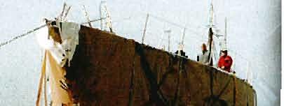
4 William Kemps specifications for a rigid lifting device of 1835, the forerunner of the modern flexible bag. The Wreck of the Earl Grey in 1847, with lifting caissons attached and inflated, ready for recovery. The wreck of the Earl Grey, 1847, supported by floatation bags being towed the 20 miles to Burnham, by the steamer Fly.
5 BASIC THEORY THE THEORY OF LIFTING BAGS Safe and effective utilization of lifting bags underwater requires both the operator and the diver to have a basic understanding of certain physical laws, and the ability to make calculations relevant to pressure, volume, buoyancy etc. Without prior consideration to the weight of the object to be lifted, or the volume and number of lifting bags to be utilized, there can be no guarantee of success. Although most divers will have a certain basic appreciation of the Laws of Physics relevant to diving, i.e. Archimedes principle relating to buoyancy; absolute pressure; hydrostatic pressure and Boyles law, they may not have experience of relating these to practice, therefore a brief summary will not be out of pace. ARCHIMEDES PRINCIPLE This explains the nature of buoyancy and why certain objects become heavier on being removed from underwater. The principle states that any object, whether wholly or partially submersed in a liquid experiences an upward thrust equal to the weight of the liquid displaced. The buoyancy of an immersed object can therefore be calculated by subtracting the weight of the object from the weight of the displaced liquid. If the weight of the object is less than the weight of the displaced liquid, then the object is said to have positive buoyancy, and it will float. Should the two weights turn out to be exactly equal, then the object is said to have neutral buoyancy, which means that to have negative buoyancy, or to sink, the weight of the object must be greater than the liquid it displaces. The buoyant force of a liquid is dependent on its density, which is its mass per unit volume. Fresh water, with a density or mass of lbs per cubic ft (1000 kg/m 3 ), offers less upward thrust than salt water, which has a density of lbs per cubic ft (1024 kg/m 3 ). Hence somewhat less buoyancy is required to lift an object in the sea than the same object would require if it was submerged in a river or lake. If this is applied to a practical problem, then consider a solid block of steel, measuring 12 x 12 x 12 inches, i.e. 1 cubic foot. From a table of weights, it can be established that 1 cubic foot of steel weighs 485 lbs in air. Should this block now be completely submerged in salt water it would displace 1 cubic foot of water, which we already know weighs lbs (or 64 lbs to the nearest decimal point) (29 kg) per cubic foot. Hence with an upward force of 64 lbs the weight of the steel is now only 421 lbs (191 kg) (485 lbs - 64 lbs). In a fresh water situation the same block would have a negative buoyancy of lbs (191.7 kg), and hence is slightly heavier. Although a very simple example this serves to illustrate the need, in the best interests of safety and efficient salvage operations, to be aware of what is required to be lifted, and hence the capacity of the lifting bag necessary. HYDROSTATIC PRESSURE Hydrostatic pressure results from the weight of water acting on a submerged object: as with atmosphere above the surface, it is equal in all directions at a specific height or depth. This underwater pressure increases at the uniform rate of 14.7 lbs per square inch (1.013 bar) for every 33 ft (10 m) of depth, which equals lbs per sq. in. for every foot of descent in salt water and lbs per sq. in. in fresh water ( bar/m in fresh water or bar/m in salt water). When using lifting bags it is important to remember that whilst air is being fed inside them, there will be pressure differential due to the bags physical dimensions, and that each bag has its own designed working pressure, no matter at what depth it is being used.
6 ABSOLUTE PRESSURE Absolute pressure exerted on a submerged body is the sum of the atmospheric pressure and the hydrostatic pressure. Normal atmospheric pressure at sea level is accepted as being 14.7 psi (1.013 bar), therefore the absolute pressure at a depth of 60 ft (18.3 m) of seawater is as follows: a) Hydrostatic pressure is 60 x psi = 26.7 psi (1.84 bar) b) Atmospheric pressure at sea level = 14.7 psi (1.013 bar) c) Therefore absolute pressure is = 41.4 psi (2.853 bar) Absolute pressure may be expressed as atmospheres absolute, i.e. at (c) or as pressure in pounds per square inch absolute or psi (c). Having considered the various pressure effects on a lifting bag depth, it is now necessary to look at the result of bringing that bag to the surface, still inflated. All divers are aware of the dangers of holding ones breath during ascent, which can result in a ruptured lung as the expanding air seeks a form of escape; the same basic physics applies to a lifting bag on ascent, and for the same reasons the diver must ascend at a controlled rate, exhaling or venting as he goes up, so the lifting bag must be vented, otherwise it will burst. BOYLES LAW Boyles Law states that at a constant temperature, the volume of any gas will vary inversely with the absolute pressure, whilst the density will vary directly with the pressure. In simpler terms, the pressure increases, the volume will decrease, and as the pressure decreases (as when returning to the surface), so the volume of gas will expand. Whilst the density and temperature are important considerations in scientific work, for practical salvage purposes, they can be ignored, and we need only be concerned with the matter of contraction and expansion as the depth alters. If we consider how Boyles Law relates to a 1 tonne lifting bag, with a capacity of 35 cubic feet(1 m 3 ) of air, first at the surface and submerged, the basic formula for a practical use is: V1 = (P1 x V2) / P2 where: V1 = The air capacity of the bag at 1 atmosphere absolute (14.7 psi). V2 = Resultant volume in cubic feet. P1 = Starting pressure in psi (a). P2 = New pressure in psi (a). What will happen to the volume of the bag if it is now taken from the surface to a depth of 60 ft (18.3 rn) in sea water? Firstly, calculate the absolute pressure relevant to the maximum depth, i.e: 60 x = 41.4 psi (a) or 18.3 x = 2.85 bar Resultant volume at depth = 14.7 x 35 or = x = cubic feet = m³
7 If the lifting bag were completely full of air at the same depth of 60 ft of seawater, what volume would have been vented off as a result of the decreasing pressure on returning to the surface? Resultant volume at surface = 41.4 x 35 or = 2.85 x = 105 cubic feet =2.81m 3 Hence the volume vented off is the resultant volume at the surface, minus the bag capacity, i.e.: Volume to be vented = or = = 70 cubic feet = 1.81 m 3 A useful rule-of-thumb is to remember that the 35 cubic feet of air is required to lift 1 ton (long) or 2240 lbs. i.e.: 2240 lbs = 35 ft 3 64 PRACTICAL CONSIDERATIONS With some appreciation of the basic physics and calculations involved, let us now consider a theoretical problem in more detail: Assume that there is a piece of wreckage at the depth of 75 ft in the sea, which is to be raised. The basic information required is necessary in order to answer the following four questions: a) What is the net in water weight of the wreckage? b) What is its displacement? c) What number and volume of lifting bags are necessary? d) What minimum volume of air will be necessary? Assume that the estimated mass of the wreckage is 9 tons (long), and that the material is steel. Now convert the estimated mass into lbs: 9 x 2240 = 20160lbs Also determine, from the given table of Densities of Material, the density of steel measured in lbs/ft 3 : Density of steel = 485 lbs/ft 3 a) Gross weight in lbs in air = Displacement in ft 3 Density of Material = ft 3 Displacement in ft 3 x wt of 1 ft 3 seawater = Buoyancy force (in lbs) ft 3 x 64 lbs/ft 3 = 2,660 lbs
8 Therefore the in water weight = = lbs NB: This in water weight is only estimated, since it is difficult to obtain an accurate measurement of weight of irregular objects underwater. b) In water weight of item in lbs = total displacement to achieve neutral buoyancy. = ft 3 Wt of 1 ft 3 seawater in lbs c) Lift in tons = displacement(ft³) = vol to lift 1 ton in ft³ 35 Therefore to render the lift neutrally buoyant only, it would be necessary to apply tons. To achieve positive buoyancy, 8 tons of lift would be a reasonable calculation, depending on the geometry of the lift. Of the 8 tons of lift at least 1 ton would be used as buoyancy control (see comments later). Note that tons represents 97.65% of the 8 tons of lift available, therefore 2.35% or 421 lbs would represent the positive buoyancy. i.e tons tons = x 2240 lbs 421 lbs divided by 64 lbs lifting capacity of 6.58 ft 3 d) (i) Absolute pressure in atmospheres and psi: =421 lbs 75 ft depth x lbs/ft change = 48 psi (a) 48 psi (a) 14.7 psi = Atm (a) (ii) Total volume of air required to inflate lifting bags representing 8 tons at 75 ft depth 8 tons x 35 ft 3 x Atm(a) = 914ft 3 Since a compressor would be required to supply this volume of air, assume a supply capacity of 75 ft 3 per minute, then it will take approximately 12 minutes to inflate, but allowing a 1/3 increase for flow loss in the hose, then the time taken to inflate will be: ft 3 min = minutes x 0.33 = 4.05 minutes Total time = = or 17 minutes.
9 AIR REQUIREMENTS FOR LIFTING BAGS Using the rule of thumb, already mentioned, that it takes 35ft 3 of air to lift 1 ton, it follows that a 3 ton lifting bag would require: 35 x 3 = 105ft 3 air [at 1 Atm (a)] However, with a pressure relief valve fitted, which ensures that the internal pressure is maintained at 2 psi above ambient, then more than 105 ft 3 will be required. Since 2 psi is 13.6 % of 1 atmosphere: ( psi) x 100 = 13.6% Thus, for a 3 ton bag with a relief valve, the revised volume of air necessary is: 105 x = 9.28 ft 3 Considering a more practical problem; what calculations are necessary to use the 3 ton totally enclosed air bag at a depth of 50 ft in seawater with a compressor of 50 ft 3 per mm available? a) Absolute pressure depth: ft = 83 ft. b) Atmospheres absolute: = 2.5 atm c) Air required for 3 ton bag: 35 x 3 = 105 ft 3. d) 2 psi over-pressure = atm. e) Total air required to operate relief valves at one atmosphere absolute: = ft 3. f) Total air required at 50 ft: 105 x = ft 3. g) Compressor time to fill bag: cfm = 4.70 mins. h) Air flow loss in hose: 4.70 x = mins. i) Total time to fill bag: = 6.27 mins. A major advantage of the totally enclosed lift bag is the ease with which surface towing can be achieved with the bags still fitted, this may eliminate the use of a crane barge for example, and hence greatly reduce the cost of a contract. EXAMPLE Whilst the previous example was calculated in imperial units, it may be necessary to be familiar with the same sort of calculations based on metric units. The following two examples show the working for both imperial and metric units. What is the weight of a block of concrete measuring 46 x 30 x 23 cm (18 x 12 x 9 in) in air? What will its weight be when it is submerged in saltwater?
10 IN AIR In Metric Units W =pv p = 2323 kg/m³ V = 46 x 30 x 23 cm³ Convert to metres³ In Imperial Units W =pv (see density table) p = 145 lb/ft³ V = 18 x 12 x 9 in³ Convert to feet³ = 46 x 30 x 23 = 18 x 12 x = m³ = ft³ W = 2323 kg/m³ x m³ W = 145 lb/ft³ x ft³ = kg = lbs UNDERWATER Wsub = V (po pw) V = m³ po = 2323 kg/m³ (from table) pw = 1026 kg/m³ (from table) Wsub = V (po pw) V = ft³ po = 145 lbs/ft³ (from table) pw = lbs/ft³ (from table) = x ( ) = x (150 64) = 41.2 kg = lbs Having looked quite closely at the theoretical aspects of this subject, let us now consider the practical application, and the first consideration must be how much positive buoyancy is required in a lift? One of the major problems associated with the buoyant recovery system is controlling the ascent velocity once the actual lift has commenced. This is particularly true of collapsible lifting bags for a number of reasons. If the load is less than the bag capacity, ascent will commence before the bag has reached its maximum displacement. As it ascends, the gas will expand within the airbag, hence increasing its net buoyancy, which in turn will increase the ascent rate. Therefore it is important to use a bag fitted with a pressure relief valve. It is most important to select bags with a lifting capacity equal to the load, with possibly a smaller bag or crane assistance to provide the positive buoyancy control required. In any event, the ascent rate should never exceed 2-3 feet per second. What might be the result of too fast an ascent rate?
11 Should a lifting bag rise at a rate faster than 10 feet per second, a phenomena known as a velocity-head may develop on the top surface, in which the force due to the upward motion reacts against the top face, forming a pressure head, deforming the bag and causing it to become unstable. In an extreme situation this may cause the bag to dump air, lose buoyancy and thus let the load return to the bottom. The ascent rate is therefore vital to the successful outcome of any lifting project. Accurate estimation of acceleration and final ascent speed is more difficult than the previous calculations. Initial acceleration is given by the total lift force divided by the total payload mass. In this case, in addition to the payload itself, the mass includes an unknown quantity of entrained or trapped water. The final ascent speed is determined by the total lift force; which is in turn determined by the shape and drag area of the lift bag and payload combination. The form of the equation is: Lift Force = Mass x Acceleration + Pressure Drag + Friction Drag Lift Force = M x Acc x p x V 2 x [Cp x Al + Cf x A2] Where: M = Total mass (including added mass of water) Acc = Acceleration p = Water density Cp = Pressure or Form Drag coefficient - an empirical constant A1 = Cf = Horizontal area presented by payload and lift bags Friction Drag coefficient -a part empirical constant which also includes viscosity A2 = Surface area in contact with flow Accurate selection of bag capacity for precise acceleration and speed control is difficult because of the uncertainty in estimates of M, Cp and Cf; and also possibly A1 and A2. A rule of thumb, which has been found to give satisfactory results, and avoid excessive ascent speeds is to provide a lift force which is not more than 20% greater than the payload in-water weight.
12 TABLE OF DENSITIES OF THE MORE COMMON MATERIALS Material kg/m 3 lb/ft 3 Aluminium Asphalt Brass Brick, common Bronze Cement, Portland Cement, Portland (set) Chalk Clay (wet) Coal (anthracite) Coal (bituminous) Coke Concrete masonry Copper ore Corn (bulk) Glass Gravel Iron, cast Kerosene Lead Limestone Manganese ore Mortar, rubble Nitrates (loose) Oils, mineral Paper Petroleum, crude River mud Sand Sandstone Steel Tin Zinc
13 VOLUME OF AIR REQUIRED BY STANDARD RANGE BAGS AT DEPTHS Ambient Pressure ats Depth m SPD1, M1 litres SPD2, M2, T2C litres M5, T5C litres M10, T10C litres PR1, T1, TARB1 litres PR1V, PR1VM litres PR2, T2 litres PR3, T3 litres PR5, T5 litres PR10, T10 litres PR20, T20 litres PR35, T35 litres TO CONVERT MULTIPLY BY Atmospheres to feet of water Atmospheres to pounds per square inch Bars to atmosphere Bars to lbs per square inch Cubic feet to cubic metres Cubic feet of water to lbs Cubic feet to gallons Cubic metres to cubic feet Fathoms to feet 6.00 CONVERSION TABLE TO CONVERT MULTIPLY BY Feet to metres Feet of water to atmospheres Feet of water to lbs per square inch Kilograms to tons Pounds to kilograms Pounds of water to cubic feet Pounds per square inch to atmospheres Pounds per square inch to feet of water Tons to kilograms
14 PLANNING, MOBILISATION AND IMPLEMENTATION Each phase of the lifting operation should be planned in advance, discussed with the personnel involved, and in particular the divers who will be carrying out most of the work. In the task of lifting and recovery, no matter how small the operation, the importance of planning cannot be over emphasized, but in order to achieve the best results, full details of the work must be available. The following is a short list of the basic information required for a typical salvage recovery task: 1) An exact location of the object to be recovered: i.e. Decca or Hi-Fix position; visual transit marks; sextant angles; object is already buoyed or marked on the surface. Appropriate chart position: echo sounder trace etc. 2) The attitude of the object on the bottom. 3) The nature of the seabed on which the object rests. Is it such that the object may be part buried? Is there any overburden, sitting etc, which may affect break-out of the object, and will any prior water jetting or airlifting be necessary before recovery? 4) The nature of the object itself: are there any plans or drawings available which will help establish its centre of gravity, capacity of hollow spaces or internal compartments and materials used in construction? 5) The age and structural strength of the object: its potential stability afloat or on the surface and its ability to withstand a surface tow or wave action. 6) Is any strengthening required underwater prior to the lift, or can any particular part or parts be moved in a separate lift to reduce the weight of the main lift? 7) If the object is a vessel, is it carrying any cargo, fuel oil, hazardous materials etc? 8) What suitable attachment points are available for lifting? 9) What is the depth of water involved, tidal rise and fall, tidal stream, shipping movements, seabed obstructions such as sewer outfalls, telegraph cable, moorings, pipelines etc? 10) Within whose jurisdiction, from a maritime point of view, does the area come? Will it be necessary to have a notice to mariners warning issued for the area during work? 11) What particular safety or health precautions are going to be required for a) surface workers b) the divers 12) Is there any doubt over the ownership of the object? Is there likely to be any clash with local authority for any reason? 13) What arrangements are necessary regarding disposal of the object once it has been raised? At what point in the salvage operation do my responsibilities cease? 14) What local knowledge or assistance is there? 15) What is the weather pattern for the area on average, for the period being considered for lifting? 16) What personnel will be required, what equipment, how many lifting bags and from when to when? 17) Insurance. Who pays if it goes wrong?
15 Experience has shown that the following parts or points on a vessel are of sufficient strength to be used to assist a buoyant lift: a) Hawser pipes, but on steel vessels only. b) Scupper holes, but on steel vessels only. c) Propeller shafts. d) Rudder posts. e) Portholes or scuttles, depending on their position and on steel vessels only. f) Engine mountings. g) Anchor windlass and cargo winches. h) Propeller shaft A frames and brackets. i) Gantries, Samson posts and derrick mountings. LOW TEMPERATURE OPERATION Although the fabric used for the manufacture of the air bag has a temperature operating range of-40 C to 100 C, when using the air bags at -40 C it is s trongly recommended that the air bags are not unfolded until they are totally submerged in the water.
16 ENCLOSED CYLINDRICAL TYPE BAGS RIGGING & INSTALLATION When used correctly to lift a load, and with all the pressure relief valves operating, this type of bag is particularly suitable for shallow water due to its low profile and shallow draught. A major problem with the parachute type bag is the danger of air loss on the surface, this problem has been overcome by the totally enclosed bag. These are fitted with one or more pressure relief valves, set to maintain a differential of 2 psi. These valves are extremely important to the successful operation of these bags, and their failure may cause a bag to rupture on or below the surface. Maintenance of the valves is therefore most important after use. The valves should be tested and valve diaphragms seen to be free to operate. For inflation, totally enclosed bags are generally fitted with ball type valves with lever handles. Great care is necessary in rigging to ensure that these handles do not foul the rigging lines, straps or samples. The number of lifting points, pressure relief and inlet/outlet valves fitted are dependant on the size of the bag. When using lifting bags with multiple lifting points, it may be necessary to consider a lifting beam or strongback to distribute the lift, hence minimizing bag distortion. It is important to use totally enclosed bags with a total capacity slightly in excess of the load to be lifted. Always remember that a fully inflated lifting bag is not intended for a free unloaded flight to the surface. The rapidly expanding air may overwhelm the pressure relief valves, causing the bag to rupture, in which case it is possible that the remaining buoyancy will allow the load to sink, and in a tide way, the load may drift to the bottom some distance away and even be lost. The pressure relief valves specified and used by J W Automarine Ltd will dump approximately 1.7 ft 3 of air per second, or 103 ft 3 per minute. Since the pressure relief valve is adjusted to maintain an internal pressure of 2 psi above ambient, the working pressure of these bags is 2 psi. When rigging and installing totally enclosed air bags it is most important to ensure that they are operated in the horizontal plane, +/- about 5º. Should they be inclined at more than 5 excessive tension will be placed on the cradle strap and securing panels to such an extent that the straps could tear away from the air bag. TOTALLY ENCLOSED AIR BAGS SHOULD NEVER BE RIGGED IN THE VERTICAL POSITION. It is also most important to ensure that the various anchor points are kept the same distance apart and not tethered together on the same pick up point. Should it not be possible to achieve this, it is recommended that a steel liftbeam or strongback be used (see drawings section), with the airbag being connected to the various anchor points on the lifting beam and the load connected to the two lower anchor points. It is important to ensure that when the lifting bags are attached, they are trimmed and set correctly, each half-filled whilst a last check is made, after which they should be completely filled. Do not fill all the bags at one end together, but distribute the lift evenly around the object. When on the surface, an additional amount of buoyancy, equal to one third of that already used should be added as a safety factor, before commencing any sort of towing operation. There is a requirement for some basic seamanship and an understanding of breaking strains when rigging lifting bags, which will certainly involve rope, wire and possibly chain, webbing slings, shackles, stoppers, hooks, thimbles and the like. When dealing with any natural or synthetic rope, wire or chain, each has a safe working limit (S.W.L) which is greatly influenced by the manner in which it is used. For instance, the minimum bending radius of most rope and cable is its diameter x 3, therefore, to pass a steel cable through a hole in a piece of steel plate 3/8 thick, and shackle it to a 5 ton lifting bag, is asking for trouble. The wire will then have been reduced in strength by about 50%, and when the load is applied, will part, leaving the bag free to head for the surface. If the bags have to be anchored in this manner, then wood packing strips will help increase the diameter of the bend, alternatively increase the cable size to compensate or use a chain with appropriate size shackles instead of wire. In the same way, splices greatly reduce the strength of wire and rope, and knots and hitches in rope weaken its SWL by as much as 60 to70%.
17 GENERAL HINTS ON THE USE OF TOTALLY ENCLOSED AIR BAGS The following notes are relevant: a) When rigging and installing totally enclosed air bags it is most important to ensure that they are operated in a horizontal plane. Should they be inclined at more than 5, excessive tension will be placed on the cradle strap and securing panels to such an extent that the straps could tear away from the air bag. TOTALLY ENCLOSED AIR BAGS SHOULD NEVER BE RIGGED IN THE VERTICAL POSITION b) Always use a total lifting force at least equal to the weight of the load, but remember too little will not lift, too much may cause the load to ascend out of control or even be lost. c) Place the bags as to minimise stress differentials. Uneven lifting stress may well cause physical damage to the load as well as endanger the divers. Attach and inflate bags methodically when used in groups or clusters to avoid one forcing another to collapse. d) Do not allow a load to ascent at a rate faster then 2-3 feet per second. e) Bags should be inflated evenly on the load to prevent rolling or tipping. f) Use extreme caution when employing excess buoyancy to break-out a load initially. g) When attached to the underside of a load, great care is necessary to ensure that airbags are not pinched or strangled as for example by the bilge of a vessel. In such cases, air will not be free to pass to all the bags, hence reducing the potential lift. h) Towing speed should be kept to 2-3 knots depending on sea state. Exceeding this recommended speed could cause pressure build up in front of the bag and reduce volume. i) After use, whether in salt or fresh water, the bags should be washed off, lightly scrubbed if necessary to remove mud, oil, tar etc, then hung up to dry. Inspect all the lifting strops carefully. Damaged straps or fastenings may govern the success or failure of the next task. It is almost impossible to avoid some damage, and straps showing exceptional ware should be replaced (refer to Inspection & Repair Section).
18 OPEN BOTTOM PARACHUTE TYPE BAGS (M & PR RANGE). RIGGING AND INSTALLATION This type of unit is ideal for deep salvage, being open bottomed the expansion of air on ascent is exhausted from the bottom of the bag. Each unit is fitted with lanyard operated dump valves, and for the models PR3 - PR35, ¾ inlet valve. Air inlet assemblies are fitted as standard and are optional for the remaining M and PR models. All units are supplied with single point lifting shackles are immediately ready for use. As with totally enclosed units, it is important to ensure that the total capacity is only slightly in excess of the load being lifted. When rigging a series of bags, ensure that a balance is achieved and that the fixing points are strong enough to take the load of the lifting capacity of the unit being used. GENERAL HINTS ON THE USE OF OPEN BOTTOM PARACHUTE TYPE LIFT BAGS The following notes are relevant: a) Always use a total lifting force at least equal to the weight of the load, but remember, too little will not lift, too much may cause the load to ascend out of control or even be lost. b) Place the bag so as to minimize stress differentials. Uneven lifting stress may well cause physical damage to the load, as well as endanger divers. Attach and inflate bags methodically when used in groups or clusters to avoid one forcing another to collapse. c) Do not allow a load to make a free ascent at a rate faster than 2-3 feet per second. d) Bags should be inflated evenly on the load to prevent rolling or tipping. e) Use extreme caution when employing excess buoyancy to break-out a load initially. f) After use, whether in salt or fresh water, the bags should be washed off, lightly scrubbed if necessary to remove mud, oil, tar etc, then hung up to dry. Inspect all of the lifting straps carefully. Damaged straps or fastenings may govern the success or failure of the next task. It is almost impossible to avoid some damage, and straps showing exceptional wear should be replaced (refer to Inspection & Repair section).
19 UNDERWATER LIFTING BAG GENERAL USERS GUIDE This is not comprehensive but is intended to assist an operator employing lifting bags by mentioning some of the basic principles. 1. Study the problem carefully and log all the available information to build up a complete picture of the situation. Where applicable include: a) Weight, dimensions and stability of the object to be raised. b) Type of construction and suitable attachment points for bags. c) Depth of water. d) Accessibility. e) Tidal predictions. f) Weather predictions, especially winds. g) Intended disposal of raised object and where responsibility of it lies. 2. Estimate the weight, obtaining as much information as possible from builders and drawings etc, allowing for additions and/or modifications which may have been made to the original object. 3. From the above assess the type and number of bags required. For shallow lifts, and where a tow is anticipated, totally enclosed bags may be used, but in most cases the parachute type is preferable. Use the minimum amount of lift necessary to achieve the desired result as this will avoid excessive ascent rates. The strength and number of fixing points and the stability of the object may dictate the number of bags to use. 4. To calculate the amount of air required add the displacement of all the bags used together and multiply by the absolute pressure at the depth of the object expressed in atmospheres. Relate this to compressor output and allow about 30% loss in the air lines and you can assess the inflation time. 5. Plan the operation in detail taking all the above data into account and if possible ensure that all personnel involved have a copy of your program. NOTES 1 Avoid unduly high ascent rates as forces are produced which can distort the shape of the bag and induce instability, which, in extreme cases, may cause air dumping and consequent buoyancy loss. 2 When using totally enclosed bags it is essential that they are secured in such a way that they remain horizontal throughout the lifting operation. If they deviate the air will migrate to the higher end of the bag causing deformation and loss of efficiency. 3 All lifting bags in J.W.Automarine s standard range are supplied with carefully designed harness straps of adequate strength and suitable shackles. They are also equipped with hose couplings, inlet, relief and dump valves where appropriate. 4 Care should be exercised in all lifting operations both above and below water -check and double check everything! 5 When they are securely attached, partially inflate the bags prior to commencing the lift. This ensures that all straps are correctly positioned and the bags assume their shape. After which the bags are fully inflated for the final ascent.
20 INSPECTION AND REPAIR CONTENTS INSPECTION OF TOTALLY ENCLOSED LIFT BAGS 1.0 INSPECTION OF PARACHUTE LIFT BAGS 2.0 INSPECTION OF TEST PLUGS 3.0 INSPECTION OF WEBBING SLINGS 4.0 INSPECTION OF SHACKLES AND MASTER LINKS 5.0 HOT AIR GUN REPAIR PROCEDURE 6.0 SAFE WORKING LOAD TEST 7.0
21 CODE OF PRACTICE FOR THE INSPECTION, REPAIR AND CERTIFICATION OF UNDERWATER LIFTING BAGS TO SAFE WORKING LOAD STANDARDS. This inspection procedure should be carried out at 6 monthly intervals. 1.0 TOTALLY ENCLOSED LIFT BAGS General Inspection 1.01 Select a clean and dry environment with good lighting. Ensure the lifting bag is free from dirt and grease and is generally in a clean condition With a totally enclosed lift bag, fully inflate until the pressure relief valves vent and air can be felt coming through all the valves. It may be necessary where more than one valve is installed to cover or temporarily plug one valve in order to get all the valves to vent. This is purely due to slight variances in the valve spring retention settings and will not adversely affect the performance of the air bag. Should a pressure relief valve prove defective replace immediately with manufacturers approved parts. Similarly, the inlet valve should be inspected, and any damage repaired using manufacturers replacement parts. Particular attention should be paid to the areas around both the inlets and pressure relief valves. Any sign of wear should be repaired immediately by the manufacturer When fully inflated carefully inspect the main bag skin and strap panels for any tears, abrasions or cuts. If necessary, soapy liquid can be used to identify leaks around any slightly damaged areas. Small tears, abrasions or cuts can be repaired using a standard hot air welding technique. Where there are any larger cuts, leaks or abrasions in excess of 4 long the bag should be returned to the manufacturer for factory repair IMPORTANT. Should a cut or tear go across and sever or partially sever a welded seam the bag should be withdrawn from service immediately and returned to the manufacturer for assessment and factory repair Slightly deflate the air bag and inspect the webbing straps. Inspect the webbing in accordance with section 4.0 of this manual Inspect any shackles and master links in accordance with section 5.0 of this manual Any hot gun repairs are to be conducted in accordance with section 6.0 of this manual. 2.0 PARACHUTE TYPE LIFTING BAGS 2.1 To inspect parachute type lifting bags the following equipment will be necessary: a) Test plug TB - PR2, PR3 and PR5 b) Test plug TBI - M5, M10, PR1 and PR1V c) Test plug TB2 - PR10 PR20 d) Test plug TB3 - PR Lay out the parachute bag in clean, well lit area. Remove the main lifting shackle(s) to allow easier fitting of test plug and place the test plug into the mouth of the bags and inflate using a suitable compressor. Make sure that the test plug inflates evenly and locks itself into the mouth of the bag. Continue inflating until the lift bag is fully inflated CAUTION! Because the PR type lifting bags do not have pressure relief valves extreme caution should be used to ensure that the bag is not over inflated. Once the bag has formed its shape and is firm to the touch the compressed air should be turned off prior to the beginning of the inspection procedure and only turned on again for topping up purposes should the air bags being inspected become too soft to handle. Under no circumstances should the air bags be left unattended during the primary inflation sequence.
22 2.04 Carry out the inspection procedure as per 1.0 of this manual, as applicable. 3.0 TEST PLUG 3.01 Close attention should be given to the general condition of the test plug. It is possible that the plug may fail if damage has occurred so as to weaken the structure of the test plug. For inspection and repair instructions refer to sections 1.0 and 6.0 of this standard. 4.0 INSPECTION OF WEBBING SLINGS The webbing straps should be inspected using the following guidelines as contained in BS EN :2000 Flat lifting Slings : 4.1 i) Slings should be examined throughout their length for surface chafe, cross or longitudinal cuts in webbing, cuts or chafe damage to the selvedges, or any damages to the stitching, eyes or end fittings. ii) The effect of the chafe on the fabric surface is variable, but some loss of strength should be expected. Any substantial chafe, particularly localized, should be viewed critically. Local abrasion, as distinct from general wear, may be caused by the passage of the sling over sharp edges under tension and may cause a serious loss of strength. iii) Chemical attack is indicated by local weakening or softening of the material in the webbing so that surface fibres can be plucked off, as a powder in extreme cases. iv) Cuts, particularly at the selvedge, will result in a serious loss of strength. A sling so affected should be taken out of service immediately. v) Seams should not be allowed to deteriorate Where required additional inspection may be necessary as listed below: i) Lay the sling on a flat surface in a well lit area. ii) Examine both sides of the sling. iii) Endless slings must be examined over whole length. iv) The inside of sling eyes should be examined with particular care. v) All equipment should be examined by one person only Sling Damage Polyester webbing slings lose strength either from fair wear and tear or physical damage due to misuse, thereby reducing the safety factor. If at all in doubt the sling must be discarded and a new replacement fitted. On inspection of a sling it should be possible to recognise the early signs of strap deterioration, so that wherever possible, the cause can be analyzed and corrective action initiated to prevent further damage and ultimate failure TYPICAL CAUSES AND RESULTS Friction damage I - Burning Overloading or wrong positioning of sling is the most frequent cause of this damage. When the webbing is pulled quickly over or along even smooth edges of very heavy goods, the heat created is so great that it melts the surface of the webbing. This damage is usually across the whole width of the webbing. The surface of the web will be hard and brittle to touch and will shine, easily reflecting light. The best way to examine the extent of the damage is to fold the webbing to see the extent of the burning. The sling should always be replaced.
23 Friction damage II - Cutting Cuts result from unprotected sharp edges on the sling. The damage is similar to that of burning except that the cut may be clean or matted and soft in appearance. Examination for the extent of damage is the same for burning. It is common for a cut to be combined with surface burning, the sling should always be replaced Friction damage III - Wear Damage from wear arises in localized areas only caused by dragging along the ground. A scuffed surface will appear in patches. If the scuffing is severe and whole threads are broken, the sling should always be replaced Impact damage I - Unbroken load bearing threads Usually the longitude threads burst out from the middle or sides. If they are unbroken, there is no loss of strength. The threads can catch and break if left unattended, but they are easily repaired Impact damage II - Broken load bearing threads Since the load bearing threads are broken, the strength of the webbing has decreased, very often at a higher degree than corresponds with the number of broken threads. It is imperative to replace this sling Sling eye damage - Webbing burst at edges This damage is nearly always caused by using a hook with a radius smaller than the webbingwidth. The sling should always be replaced Strop eye damage - Burst leather protection This damage only occurs when the SWL has been exceeded. The leather protection is easily repaired but close inspection of the rest of the sling is imperative Seam and stitch damage Particular attention should be paid to the condition of the sewn joints and seams. Where there is any identification of loose or torn stitching then the webbing straps should be replaced with manufacturers replacement part Chemical damage The deleterious effect of chemicals on polyester of polyamide slings is difficult to judge. Some cannot be seen until in an advanced stage of deterioration. If there is the slightest doubt, the sling must be replaced. 5.0 INSPECTION OF SHACKLES AND MASTER LINKS Examine all shackles and master links for mechanical damage. Pay attention to all screw threads. Where there is any sign of wear or damage then the complete shackle or master link should be replaced. 6.0 HOT AIR GUN PROCEDURE The general procedure for using a hot air gun is as follows: 6.01 Lay out air bag in clean dry and well lit conditions Select or cut a patch from the material supplied in the repair kit. To make an effective repair the patch should overlap by a minimum of 80mm (3 inches) around the damaged area Adjust the heat setting on the base of the hot air gun and switch on. Allow the gun to heat up thoroughly. The recommended setting for the heavy fabric is between 7 and 9.
24 6.04 Do some test welds to fine tune the heat setting. When pulling apart, one layer of PVC should pull off leaving the polyester weave uncovered Clean the area to be patched as thoroughly as possible. A general PVC cleaning solvent should be used. Position roller in the centre of the patch (see fig 1). Lift one edge and slide gun between patch and bag surface up to position of roller. Maintaining a firm and even pressure on the roller, draw the gun carefully to the edge of patch while steadily following with the roller. Work this principle until the whole patch has been welded, always working from centre to edge. Care should be taken not to allow the nozzle to come into contact with the bag. Localized burning will result. When the repair has been completed, heat edge of patch with gun, angling head of roller at approximately 45 degrees to chamfer the edge of patch to give a smooth finish. Patches welded on the outside of the bag are generally found to be adequate, however where the patching area is restricted on the outside of the bag, a second patch inside is essential The hot air gun can be used for any splits/holes up to 8 or 200mm long, larger damage should be referred back to the manufacturer, especially where tears or cuts sever or partially sever any main seam or where size of the patch is restricted by valves, anchor tabs etc. Hot air gun patches should extend no less than 80mm all the way round a repair for maximum strength. 7.0 SAFE WORKING LOAD TEST 7.01 To test the air bag to safe working load limits a suitable gantry or crane will be required together with a good water supply and load cell or gauge calibrated and certified to a recognized standard. Ensure test equipment is suitable for the loading required Suspend the air bag and load cell/gauge from the gantry and gradually fill with water to the required amount. During the filling process carry out a final inspection of the airbag to ensure there are no further leaks in the air bag skin and all the webbing straps, links and shackles come under tension in the correct fashion and are not twisted. RECOMMENDATIONS FOR THE STORAGE OF LIFTING BAGS. 1) After use, the airbags should be washed in soapy water using a mild detergent. They should then be washed down with clean water to remove any remaining detergent. 2) After cleaning and prior to the next use, all airbags should be inspected as per the Inspection & Repair Section of this manual. 3) All airbags should be stored in a cool dry place, away from direct sunlight.
25 DRAWINGS HOT AIR GUN REPAIR PROCEDURES LIFTBAG INSPECTION CHECKLIST 5 TONNE LIFTING BEAM T5 TOTALLY ENCLOSED LIFTING BAG 10 TONNE LIFTING BEAM T10 TOTALLY ENCLOSED LIFTING BAG PR5 OPEN BOTTOM PARACHUTE LIFTING BAG PR1 OPEN BOTTOM PARACHUTE LIFTING BAG M10 OPEN BOTTOM PARACHUTE LIFTING BAG M25 OPEN BOTTOM PARACHUTE LIFTING BAG LARGE DUMP VALVE ASSEMBLY A10 DUMP VALVE ASSEMBLY A10 RELIEF VALVE ASSEMBLY A6 DUMP VALVE ASSEMBLY 3/4" BALL VALVE ASSEMBLY
26
27
28
29
30
31
32
33
34
35
36
37 C A If In Doubt ASK! A B B C C D D E E F F G G Dimensions In MM File Name H Tolerance Material H J Drawn SBG Sig SCHOLLE EUROPE LTD t/a J.W. Automarine Present. This article and drawing is protected by copyright and is the property of Scholle Europe Ltd. It may not be copied, published or used for any purpose other than for which it has been supplied, except with the written permission of Scholle Europe Ltd. Revisions Issue Date SCHOLLE EUROPE LTD. t/a Enterprise Way Fakenham,Norfolk,NR21 8SN,England Telephone. Fakenham(01328) Fax. . Fakenham(01328) sales@jwautomarine.co.uk Client R R J Scale 3:1 K ON A1 Checked Title Drawing No Sheet No Issue No Date K A10 Manual Dump Valve

38 Fakenham(01328) If In Doubt ASK! A A B B C C D D E E F F G G File Name Dimensions In MM H Tolerance Material H J Drawn SBG Sig C SCHOLLE EUROPE LTD t/a J.W. Automarine Present. This article and drawing is protected by copyright and is the property of Scholle Europe Ltd. It may not be copied, published or used for any purpose other than for which it has been supplied, except with the written permission of Scholle Europe Ltd. Revisions Issue Date SCHOLLE EUROPE LTD. t/a Enterprise Way Fakenham,Norfolk,NR21 8SN,England Telephone. Fakenham(01328) Fax. . sales@jwautomarine.co.uk Client R R J Scale 3:1 K ON A1 Checked Title Drawing No Sheet No Issue No Date K A10 Pressure Relief Valve 2 P.S.I
39 A If In Doubt ASK! A B B C C D D E E F F G G Dimensions In MM File Name H Tolerance Material H J Drawn SBG C SCHOLLE EUROPE LTD t/a J.W. SCHOLLE EUROPE LTD. Automarine Present. This article t/a and drawing is protected by R copyright and is the property of Scholle Europe Ltd. It may not be copied, published or used for any purpose other than for which it has been supplied, except with the written permission of Scholle Europe Ltd. Enterprise Way Fakenham,Norfolk,NR21 8SN,England Sig Revisions Issue Date Telephone. Fakenham(01328) Fax. . Fakenham(01328) sales@jwautomarine.co.uk Client R J Scale 3:1 K ON A1 Checked Title Drawing No Sheet No Issue No Date K A6 Manual Dump Valve
40 A If In Doubt ASK! A B ITEM NO. PART NUMBER DESCRIPTION QTY /4" Skin Fitting /4" Ball Valve /4" Camlok Hosetail /4" Camlok Adaptor 1 B C /4" Locknut 1 C D D E 3 E 4 F F G G 5 Dimensions In MM File Name H Tolerance Material H J 2 Drawn SBG Sig C SCHOLLE EUROPE LTD t/a J.W. Automarine Present. This article and drawing is protected by copyright and is the property of Scholle Europe Ltd. It may not be copied, published or used for any purpose other than for which it has been supplied, except with the written permission of Scholle Europe Ltd. Revisions Issue Date SCHOLLE EUROPE LTD. t/a Enterprise Way Fakenham,Norfolk,NR21 8SN,England Telephone. Fakenham(01328) Fax. . Fakenham(01328) sales@jwautomarine.co.uk Client R R J Scale K 1 1:1 ON A1 Checked Title Drawing No Sheet No Issue No Date K 3/4" BSP Ball Valve Assembly
41 Guidance on the Use of Underwater Air Lift Bags 1 SCOPE 1.1 This guidance addresses the initial and periodic examination, testing, certification and maintenance of underwater type bags (cylindrical totally enclosed, closed and open parachute) used to lift submerged objects. 1.2 This guidance also addresses the operational use of open parachute type lift bags and the safety precautions that should be taken during their use. 1.3 This guidance does not apply to water-filled bags used as water weights for testing of other equipment. 2 OBJECTIVES The objectives of this document are to provide clear guidance on: i) Fitness for purpose; ii) iii) Examination and testing criteria; Maintenance, which should be carried out to ensure the continuing integrity of each bag, as far as is possible, between its periodic tests; v) Operational guidance; vi) Safety precautions to be taken into consideration during their use. 3 DEFINITIONS DMA dead man anchor or independent anchor point which, after assessment, is a suitable point from which to restrain the load. Dump Line this is attached to the dump valve inside the lift bag and is used for fine control and deflation of the bag buoyancy by the diver. Inverter Line this is attached to the top of an open parachute bag. Its purpose is to invert the bag if it becomes detached from the load being lifted. Restraining or Hold-back Line this is provided to restrain or hold back the positive buoyancy of the lift bag. It should be attached in such a way as to prevent an uncontrolled ascent of the load being lifted. It should be fitted between the load being lifted and a fixed point. 4 BACKGROUND 4.1 In some countries, national regulations require the initial and periodic examination, testing and certification of all items of lifting equipment. In 1993 IMCA published guidance note AODC 063 Underwater Air Lift Bags. Until AODC 063 was published, there was no guidance available specific to the air lift bags used in the underwater industry. This guidance document has
42 subsequently been updated three times, with the last update IMCA D 016 Rev.2 Underwater Air Lift Bags being published in May IMCA D 016 Rev. 2 (and the previous updated documents) based the testing of the rigging used the underwater air lift bags on the criteria defined in IMCA D 018 Code of Practice on the Initial and Periodic Examination, Testing and Certification of Diving Plant and Equipment (Ref.1), with additional information included specific to underwater air lift bags. 4.3 The normal criteria for testing of lifting equipment is to subject it to an overload test greater than its safe working load (SWL), but in the case of underwater air lift bags this is not currently considered to be reasonably practicable. However, this overload test should be taken into consideration in the design calculations. 5 NEW EQUIPMENT 5.1 Whilst this guidance does not address design and manufacturing standards, generally the onus is on the manufacturer and/or supplier of equipment to ensure that their product is fit for the purpose for which it is to be used and can be used safely. 5.2 The manufacturer/supplier should provide the purchaser with the following information and certification: i) The factor of safety to which the underwater air lift bag is designed. Usually the minimum factor of safety is 5:1 of its safe working load (SWL). (The test criteria for webbing strops is 7:1); ii) iii) iv) The design has been type tested to the stated SWL (using the factor of safety in (i) above); The bag supplied conforms to the type test; Adequate information about the use for which the underwater air lift bag has been designed; v) Details of maintenance requirements; vi) The capacity stated for the size should be plus 0% / minus 5% in fresh water. 5.3 The bag and its individual detachable lifting components, e.g. strops, rings and shackles, should each be suitably marked or labeled with a unique serial number and it s SWL. The lift bag should be supplied with a certificate stating the unique serial number, the manufacturing standard, its SWL and listing the component parts supplied with the bag. 5.4 Open parachute type bags must be fitted with a suitable attachment point at or near the crown to allow an inverter line to be attached to the top of the bag. Since bags up to 50kg SWL are not normally manufactured with an inverter line, in such cases they should be used in conjunction with a restraining line. 5.5 Totally enclosed lift bags should be fitted with relief valves. These should be tested before use and set to maintain an internal pressure sufficient to fully inflate the bag to which they are fitted.
43 5.6 A historical record for each bag should be established and become part of the planned maintenance system (PMS). 6 INITIAL & PERIOD EXAMINATION, TESTING & CERTIFICATION The categories of competent person appropriate to carry out examination, test and certification of equipment are defined in Appendix 1. Examination and test criteria are defined in Appendix 2. 7 OPERATIONAL CONSIDERATIONS 7.1 Underwater air lift bags are not just a handy tool, but also a major piece of lifting equipment and must be treated as such. They differ from conventional lifting equipment in that the loading comes from the up thrust generated by the volume of water displaced when the bags are filled with air. 7.2 As they cannot be over inflated, lift bags will not normally lift loads which are significantly greater than their designed safe working load. (The parachute type has an open bottom and when full the air spills out. The enclosed type has a relief valve that releases air when the internal pressure is approximately 13.8 kpa (2 PSI) over ambient pressure). However, it is possible for the rigging to be subjected to additional snatch loads. These can be imposed in various ways, some examples are given below: i) When the bag is used in water depths shallow enough for wave action to cause snatching and rapid changes in the dynamic loading; ii) When the bag has lifted up the load and the top of the bag is on the surface and therefore exposed to wave action; iii) iv) v) When the lift bag is incorrectly rigged; When the lift bag becomes snagged, breaks free and induces a snatch load on the webbing strops or attachment points; When the lift is assisted by a crane and there is movement on the vessel causing changes in the dynamic loading. These additional loads should be provided for in the 5:1 safety factor, discussed in paragraph 5.2 (i) 7.3 Allowance should be made for the fact that sometimes more than one lift bag is attached to the same lift point and, therefore, there will be contact between the bags. 7.4 Incorrect rigging can also cause the SWL to be exceeded on attachment points due to the uneven distribution of the load. For example, where strops of different length are used, the load imposed on the shortest strop may be in excess of the design factor and could result in failure. It is essential that no lift bag be used that has modified or replacement components which are not approved by the manufacturer. 7.5 A suitable inverter line must be fitted to parachute type bags and attached to a point on the top of the bag. This inverter line should be long enough to attach to the load being lifted, to permit the bag to invert and release the air should there be a failure of any part of the securing rigging of the bag. It should be strong
44 enough to resist the snatch load caused by a rapidly ascending bag, bearing in mind that a longer inverter line will allow the bag to achieve a greater upwards velocity and, hence, will create a larger snatch load. Since bags up to 50 kg SWL are not normally manufactured with an inverter line, in such cases they should be used in conjunction with a restraining line. 7.6 A suitable restraining line should be fitted between the load being lifted and DMA or other subsea structure that is not part of the load being lifted (see 8.7). This line should be arranged in such a way to resist a snatch load caused by a rapidly ascending load and to stop an uncontrolled ascent. The restraining line should not be attached to other adjacent subsea equipment or structures which could themselves be damaged or cause hazard in the event of a failure. Consideration should be given to the material selected for use as the restraining line as it may be subjected to snatch loading. Consideration should be given to the length of the restraining line to avoid unnecessary slack. OPERATIONAL GUIDANCE A sketch illustrating a typical example of subsea rigging of parachute bags is shown at Appendix IV. 8.1 Before lift bags are used in underwater engineering tasks, a proper assessment of the task to be performed should be made. This assessment should include: (i) Calculations of the weight to be lifted or moved; (ii) Calculations of the size of the lift bag and type (enclosed or open) required: (iii) Calculations, where possible, to determine the centre of buoyancy and centre of gravity should be made so that steps can be taken to prevent the object being lifted spinning or turning over; (iv) The number of lift bags required; (v) The positioning and attachment of the lift bag; (vi) Calculated safety factors for all of the above. (vii) Determining the category of lift to be carried out as this will determine the need for a restraining line and also the identification of a suitable point for the inverter line. Note 1 If the weight of the object to be lifted or moved is unknown, or the object is buried in the mud, the load can only be estimated. Precautions should be taken before the lift bags are attached to ensure that when they are inflated control of the load is not lost. The restraining line from the top of the bag, if secured to the load itself would perform its function should the lift bag attachment fail. It would not however prevent the load from going up in an uncontrolled fashion if the bag was accidentally over inflated. For this reason, the restraining line should normally be connected to an independent anchor point (see 8.7). Note 2 Extreme care should be taken when using lift bags to overcome seabed suction or free mechanically locked or snagged equipment. A hold back strop and anchor should be available which is heavier than the up thrust created by the lift bag. This can be achieved by placing Dead Man Anchors (DMA) in the vicinity of the object and attaching slings from the object to the DMA. Note 3 Only open bottom bags should be used where any form of ascent is planned or possible, such as vessel salvage or raising objects from the seabed. Fully enclosed bags should not be used for this purpose.
45 Note 4 Historically, there have been cases where the significant variations between the stated and actual capacities have been found, in some cases up to 20%. 8.2 Once the size/type and number of lift bags has been determined by the task specific assessment, then the bag(s) will need to be inspected before use for the following: (i) (ii) (iii) (iv) (v) A check of the serial numbers on all of the components with the number of the certificate. A check of the test date on the certificate. Visual inspection of all components, even if the lift bags are new. Visual inspection of the webbing strops and the stitching on the bags. The dump valve at the top of the parachute bags should be checked to ensure that it is clean and can operate freely. The line attached to the dump valve should be checked to ensure that it is attached correctly and will operate the valve when pulled. Note 5 It is recommended that these lines are made of different materials and of different sizes so as to be readily distinguishable from other lines that may be present (vi) (vii) With parachute type bags, the restraining line should be checked to ensure that it is attached to the specified inverter line attachment point of the bag so that the bag will invert should there be a failure of any part of the attached rigging. With enclosed lift bags, the relief valve should be checked to ensure that it is free and clean. 8.3 When closed lift bags are used care should be taken to ensure that they are never attached in the vertical position or can rotate into the vertical position. The manufacturer s instructions, where available, should be followed. 8.4 If it is found, during the task specific assessment, that the lift points cannot be distributed evenly along the load, a spreader bar should be used with pad eyes at equal distances on top for the lift bag slings to be attached. There should also be pad eyes on the bottom of the spreader bar to enable slings to be attached to the load. Note 6 If spreader bars are used, test certificates will be required and the safe working load marked on the bar. 8.5 If the load capacity has been estimated, it may be necessary to provide residual lift capacity. In such cases, it may be preferable to use a series of small lift bags, rather that large ones. 8.6 The use of dead man anchors (DMAs) should be included in the taskspecific assessment prior to commencing operations that involve air lift bags. The in-water weight of any DMA should be sufficient so that the combined weight of the load and any DMA is greater than the total lift force applied by the lift bag, thus preventing the possibility of an uncontrolled ascent of the load to the surface.
46 8.7 In normal circumstances the restraining line should be attached to an independent anchor point. However, there will be circumstances when the restraining line may be attached to the load, e.g. to reduce the in water weight of a trencher on a soft seabed, when the use of an independent anchorage is impracticable. This latter arrangement can only be applied when there is no possibility of the added buoyancy overcoming the weight of the load, and thereby creating a hazardous situation. 8.8 The air hose used to inflate the air bag should not be tied off to the air bag during inflation. 8.9 The selection of bags and inflation sequence should ensure that, during sub sea inflation prior to lift, the number of bags which are partially filled at any one time is minimised. In practical terms this means that each bag should be inflated to full capacity before commencing the inflation of the next The dump valve should be fitted with a dump line to enable it to be operated by the diver from a safe location. In some cases it may be necessary to extend the line to allow the diver to be in a safe position. This aspect should be taken into consideration when planning the work. Both the dump line and any extension should be of an easily identifiable colour and distinguishable from any other nearby line Weather conditions should be taken into consideration prior to the deployment of lift bags. Current and visibility as well as the water depth should also be considered When deploying two divers at one time on a project, the visibility in the area the divers are to work should be taken into consideration. Poor visibility could be an additional hazard for the divers and should be taken into account when doing the risk assessments The procedures should reflect the number of divers working on the same job. Strict controls should be in place to ensure that lift bags are not inflated or deflated until both divers have been informed and each knows where the other and their umbilicals are in relation to the work area. The supervisor must not give the order to inflate or deflate the bags until the divers are ready. 8 MAINTENANCE 9.1 Before use, all bags should be examined by a competent person. If any defects or out-of-date certification are found, the bag should not be used until repaired ad/or re-tested. 9.2 Lift bags should be washed after use with fresh water and any grease or oil removed. 9.3 The dump valve on parachute type bags should be cleaned and dried and lightly powdered with French chalk. 9.4 The relief valve on enclosed lift bags should be cleaned and lightly powdered with French chalk.
47 9.5 Once cleaned, the bag should be laid out so that it is fully extended. Fully enclosed bags should be fully inflated for inspection by a competent person. 9.6 The competent person should mark and record any defects in the historical log for that particular bag. 9.7 Any repairs should be carried out in accordance with the manufacturer s instructions. When repairs are completed, they must be entered into the log for that bag. 9.8 When repaired or ready for storage the lift bags should be checked to confirm they are dry, rolled up (not folded) and stored in a clean dry place. 9.9 An example checklist for use prior to using a lift bag and after maintenance is provided at Appendix3. 10 TRAINING 10.1 Personnel involved in the use of underwater lift bags should have a basic knowledge of the following: (i) Archimedes Principle (ii) Hydrostatic Pressure (iii) Absolute Pressure (iv) Boyles Law With an understanding of these four aspects, personnel should be more aware of what can be accomplished by the use of lifting bags, the dangers that are present and the need for caution and strict controls Training should take place to make sure that personnel have a basic knowledge of the four subjects listed above Training should be given in accordance with the manufacturer s instructions, where appropriate, and should include but not be limited to: (i) (ii) (iii) (iv) (v) Storage, examination and testing if lift bags. The deployment and rigging of lift bags. The correct way to attach the inverter line used to invert the bag. The correct way to use the dump valve and the precautions to be taken before using it. Cleaning and maintenance of lift bags after use. 11 REFERENCES 1. IMCA D018` Code of Practice on the Initial and Periodic Examination, Testing and certification of Diving Plant and Equipment`
48 APPENDIX 1 CATEGORIES OF COMPETENT PERSONS* Category 1 a diving or lift support supervisor duly appointed by the diving contractor. Category 2 a technician, certified Class 1 Chief Engineer, or other person, all specialising in such work who may be an employee of an independent company, or an employee of the owner of the equipment (unless specific legal restrictions apply), in which case his responsibilities should enable him to act independently and in a professional manner Catergory 3 normally a classification society or insurance company surveyor, but who maybe an in-house Chartered Engineer (unless legal restrictions apply), or a person of similar standing Category 4 manufacturer or supplier of the equipment, or a company specialising in such work which has, or has access to, all the necessary testing facilities. * as defined in IMCA DO18 Code of Practice for the Initial and Periodic Examination, Testing and Certification of Diving Plant and Equipment
49 Sample Check List For use prior to using a lifting bag and after maintenance. LIFTING BAG CHECK LIST APPENDIX III Customer: Serial No: Date: Certification No: Work Load Limit (SWL): Manufacturer: for ROV use for Diver use Accepted Not Accepted Comments Web Sling Lifting Bag Leak Test Tag Break in Seam Break in Bearing Threads General Condition. Master Line Shackle Ball Valve ROV use Dump Valve Diver use Fabric Restraining Line Attachment Point Dump Valve Line Colour Air 2.0 P.S.I. Preservation Dry & talc Completed New Test Comments Repair Conducted Web Sling Bag Fabric Bag Valve Water Test Leak Test Leak Test Check Conducted By: Authorised Technician.
50


51
Technical Diving Equipment. Lifting Equipment
 ing Equipment JW AUTOMARINE BUOYANCY SYSTEMS Pommec is official agent for all JW Automarine products for the Benelux. Founded in 1972, J.W. Automarine of Fakenham, Norfolk, has established its worldwide
PHYS 101 Previous Exam Problems
 PHYS 101 Previous Exam Problems CHAPTER 14 Fluids Fluids at rest pressure vs. depth Pascal s principle Archimedes s principle Buoynat forces Fluids in motion: Continuity & Bernoulli equations 1. How deep
In the liquid phase, molecules can flow freely from position to position by sliding over one another. A liquid takes the shape of its container.
 In the liquid phase, molecules can flow freely from position to position by sliding over one another. A liquid takes the shape of its container. In the liquid phase, molecules can flow freely from position
In the liquid phase, molecules can flow freely from position. another. A liquid takes the shape of its container. 19.
 In the liquid phase, molecules can flow freely from position to position by sliding over one another. A liquid takes the shape of its container. In the liquid phase, molecules can flow freely from position
Marine Kit 4 Marine Kit 4 Sail Smooth, Sail Safe
 Marine Kit 4 Marine Kit 4 Sail Smooth, Sail Safe Includes Basic ship Terminologies and Investigation Check list Index 1. Ship Terminology 03 2. Motions of a Floating Body...09 3. Ship Stability.10 4. Free
PETERSEN 161-SERIES HIGH PRESSURE LIFTING AIR BAGS OPERATING INSTRUCTIONS WARNING!
 PETERSEN 161-SERIES HIGH PRESSURE LIFTING AIR BAGS OPERATING INSTRUCTIONS WARNING! Read and understand instructions before using Petersen Plugs. Failure to comply may result in property damage, serious
POWER LIFT LOW PRESSURE LIFTING BAGS. Instructions for use
 POWER LIFT LOW PRESSURE LIFTING BAGS Instructions for use The system of WEBER-HYDRAULIK low pressure lifting bags of the 0.5 and 1.0 bar series is used particularly for rescuing persons captured in various
GOM Diving Safety Work Group
 GOM Diving Safety Work Group COMMITTEE WORK GROUP Underwater Lift bags July 15, 2014 DISCLAIMER This US GOM DSWG document is not meant to be all inclusive, and not every rule and regulation is contained
Irrigation &Hydraulics Department lb / ft to kg/lit.
 CAIRO UNIVERSITY FLUID MECHANICS Faculty of Engineering nd Year CIVIL ENG. Irrigation &Hydraulics Department 010-011 1. FLUID PROPERTIES 1. Identify the dimensions and units for the following engineering
BANKSMAN / SLINGER. 1. What is the smallest size diameter of synthetic rope allowed for use as a hand held tagline?
 BANKSMAN / SLINGER 1. What is the smallest size diameter of synthetic rope allowed for use as a hand held tagline? A. 16mm B. 10mm C. 12mm 2. What is the maximum temperature that a webbing sling can be
GLS New Technology Rising to the Challenge of Subsea lifting. Subsea 2012 Paddy Collins
 GLS New Technology Rising to the Challenge of Subsea lifting Subsea 2012 Paddy Collins Introductions Aubin Design, Develop and Supply own chemical technical technology Cement and Stimulation Pipeline products
CORPORATE SAFETY MANUAL
 CORPORATE SAFETY MANUAL Procedure No. 32-0 Revision: Date: May 2005 Total Pages: 10 PURPOSE To provide general guidelines for the inspection of all ropes, chains, cables, slings, etc. used for personnel
SECOND ENGINEER REG III/2 NAVAL ARCHITECTURE
 SECOND ENGINEER REG III/2 NAVAL ARCHITECTURE LIST OF TOPICS A B C D E F G H I J Hydrostatics Simpson's Rule Ship Stability Ship Resistance Admiralty Coefficients Fuel Consumption Ship Terminology Ship
Rapid Response Shelters. Rubber Product Manual
 Rapid Response Shelters Rubber Product Manual 1 Index Technical Data Parts List Materials List Operational Instructions Packing Maintenance & Procedures Repairs & Storage 3 4 5 6 8 10 11 WARNING: Carefully
TECHNICAL DATA. Q = C v P S
 Page 1 of 13 1. DESCRIPTION The Viking 6 Model G-6000 Dry Valve Riser Assembly consists of a small profile, light weight, pilot operated valve that is used to separate the water supply from the dry sprinkler
You may order this publication from WCB Publications and Videos, Please quote ordering number BK60.
 The following material is the property of the Workers Compensation Board of British Columbia and may not be reproduced by those outside of B.C. For those within British Columbia, this material may only
Inflatable Packer Single & Double. Single & Double Packer Dimension. Wireline Packer. Water Testing Packer (WTP) Packer
 Packer") Inflatable Packer Single & Double Single & Double Packer Dimension Wireline Packer Water Testing Packer (WTP) Packer Packer Working Pressure & Depth Chart Packer Water Hand Pump Packer Air Driven Pump
Inflatable Packer Single & Double Single & Double Packer Dimension Wireline Packer Water Testing Packer (WTP) Packer Packer Working Pressure & Depth Chart Packer Water Hand Pump Packer Air Driven Pump
THE OWNER'S MANUAL IS IN TWO VOLUMES: VOLUME 2 TECHNICAL SPECIFICATIONS - ASSEMBLY PROCEDURE ZODIAC
 CAUTION NOTICE: CAREFULLY READ THIS MANUAL BEFORE OPERATING YOUR BOAT. THIS OWNER S MANUAL IS IN TWO VOLUMES THAT MUST BE KEPT TOGETHER. THE OWNER'S MANUAL IS IN TWO VOLUMES: - VOLUME 1 DEALS WITH OPERATING
GENERAL GUIDELINES FOR PROPER RIGGING PRACTICES AND INSPECTION & REMOVAL CRITERIA FOR SLINGS PER OSHA
 GENERAL GUIDELINES FOR PROPER RIGGING PRACTICES AND INSPECTION & REMOVAL CRITERIA FOR SLINGS PER OSHA 1910.184 SAFE OPERATING PRACTICES -.Whenever any sling is used, the following practices shall be observed:
"RIGGING SAFETY IN CONSTRUCTION ENVIRONMENTS"
 PRESENTER'S GUIDE "RIGGING SAFETY IN CONSTRUCTION ENVIRONMENTS" Part of the "CONSTRUCTION SAFETY KIT" Series Quality Safety and Health Products, for Today...and Tomorrow OUTLINE OF MAJOR PROGRAM POINTS
INSTALLATION, OPERATION AND SERVICE MANUAL ABS AIR BAG LIFT
 INSTALLATION, OPERATION AND SERVICE MANUAL ABS AIR BAG LIFT P.O. Box 1058 1058 West Industrial Avenue Guthrie, OK 73044-1058 405-282-5200 FAX: 405-282-8105 www.autoquip.com Item # 830ABS Version 1.0 07/2001
Eaton Filtration, LLC
 Eaton Filtration, LLC 900 Fairmount Avenue, Elizabeth, NJ 07207 Phone: 908-787-1000 Fax: 908-351-7893 E-Mail: filtration@eaton.com Web: www.filtration.eaton.com Installation, Operation & Service Manual
Appendix 11-B Anchor Handling Systems, Set Up and Handling
 Revision History Revision Date Section Changes Number 1 Sept 1 Permanent Chaser Pendant (PCP) Drawing updated 2018 2 Pennant Buoy System Drawing updated 3 Working Wire/Chaser Termination on Drawing updated
Exercise 2-3. Flow Rate and Velocity EXERCISE OBJECTIVE C C C
 Exercise 2-3 EXERCISE OBJECTIVE C C C To describe the operation of a flow control valve; To establish the relationship between flow rate and velocity; To operate meter-in, meter-out, and bypass flow control
Technical Briefing Note
 Technical Briefing Note Subject Date Issued Revision Glossary of Terms 14th Nov 2017 Rev 3 The purpose of this Technical Briefing Note is to provide a glossary of terms commonly used in fall injury prevention
Donaghys Winch Ropes. Handling & Installation Guide
 Donaghys Winch Ropes Handling & Installation Guide September 2015 Choosing the right rope for the job It is important to choose the right rope for the job. Donaghys specialise in custom designing ropes
CRANE WITH WINCH USE AND MAINTENANCE MANUAL. Code Rev. Release MD /03
 CRANE WITH WINCH Code Rev. Release MD.0.097 0 06/03 USE AND MAINTENANCE MANUAL CONTENTS 1 FOREWORD page 3 1.1 Description of the crane with winch page 3 2 USE OF THE CRANE WITH WINCH page 3 2.1 General
Lifting Slings. Before equipment use, please read this operation manual carefully. Serial Number: Date Purchased:
 Lifting Slings OPERATION MANUAL This operation manual is intended as an instruction manual for trained personnel who are in charge of installation, maintenance, repair etc. Before equipment use, please
TECHNICAL DATA 3 MODEL G-3000 DRY VALVE RISER ASSEMBLY
 Page 1 of 13 1. DESCRIPTION The Viking 3 Model G-3000 Dry Valve Riser Assembly is equipped with a small profile, light weight, pilot operated valve that is used to separate the water supply from the dry
User Instructions 1789 Parapet Wall Anchor
 User Instructions 1789 Parapet Wall Anchor This manual is intended to meet the Manufacturer Instructions as required by ANSI Z359.1 and should be used as part of an employee training program as required
PNEUMATIC MEDIUM PRESSURE HEAVY LIFTING BAGS
 PLEASE READ AND UNDERSTAND THIS MANUAL BEFORE USING SAVA LIFTING BAGS PNEUMATIC MEDIUM PRESSURE HEAVY LIFTING BAGS & INFLATION ACCESSORIES SAFETY, OPERATION AND MAINTENANCE INSTRUCTIONS NON-COMPLIANCE
Air Eliminators and Combination Air Eliminators Strainers
 Description Air Eliminators and Combination Air Eliminator Strainers are designed to provide separation, elimination and prevention of air in piping systems for a variety of installations and conditions.
USER S INSTRUCTION MANUAL FOR THE INSTALLATION, OPERATION & MAINTENANCE OF THE GUARDIAN TEMPORARY HORIZONTAL LIFELINE SYSTEM
 USER S INSTRUCTION MANUAL FOR THE INSTALLATION, OPERATION & MAINTENANCE OF THE GUARDIAN 04630 TEMPORARY HORIZONTAL LIFELINE SYSTEM 1 WARNING This is a design compatible component for a comprehensive Guardian
Inspection & Maintenance
 PERSONAL FALL ARREST EQUIPMENT Inspection & Maintenance This article addresses the requirements of OSHA1926.502(d)(21), which states that personal fall arrest systems shall be inspected prior to each use
DIVING PHYSICS EXAMPLE QUESTIONS
 DIVING PHYSICS EXAMPLE QUESTIONS PLEASE NOTE: 1 bar = 10 Meter in Salt water 1 bar = 10.2 Meter in Fresh water. Will be GIVEN to you for calculations. 10m in Salt water = 1 bar 10m in Fresh water = 0.98
Pontoon Slide Owner s Manual
 Pontoon Slide Owner s Manual Introduction Water sports can be safe and fun for all levels of enthusiasts. The Owner s Manual is presented to enhance your enjoyment of the sport. It is intended to alert
Eaton Filtration, LLC
 Eaton Filtration, LLC 900 Fairmount Avenue, Elizabeth, NJ 07207 Phone: 908-787-1000 Fax: 908-351-7893 E-Mail: filtration@eaton.com Web: www.filtration.eaton.com Installation, Operation & Service Manual
Density. Chapters 12-14: Phases of Matter. Example: Density. Conceptual Check. Springs 2/27/12. Mass Density vs. Weight Density
 Chapters 12-14: Phases of Matter Density Sequence of increasing molecule motion (and kinetic energy) Solid Liquid Gas The densities of most liquids and solids vary slightly with changes in temperature
Stevpris installation
 chaser Stevpris deployment for MODUs Introduction Typical methods for deployment and retrieval of Stevpris anchors with an anchor handling vessel (AHV) are described, focusing on the use of chasers for
TECHNICAL DATA. Q= Cv S
 Page 1 of 13 1. DESCRIPTION The Viking 4 inch Model G-4000 Dry Valve Riser Assembly consists of a small profile, light weight, pilot operated valve that is used to separate the water supply from the dry
TECHNICAL DATA Q = C. v P S. 2 Model G-2000 Dry valve. Page 1 of 13
 Page 1 of 13 1. Description The Viking 2 Model G-2000 Dry Valve Riser Assembly consists of a small profile, light weight, pilot operated valve that is used to separate the water supply from the dry sprinkler
Chapter 2 Hydrostatics and Control
 Chapter 2 Hydrostatics and Control Abstract A submarine must conform to Archimedes Principle, which states that a body immersed in a fluid has an upward force on it (buoyancy) equal to the weight of the
SECTION PRESSURE TESTING OF PIPING
 SECTION 15044 PRESSURE TESTING OF PIPING PART 1 - GENERAL 1.01 DESCRIPTION A. Scope of Work: This section specifies the leakage and pressure testing of piping. B. Testing Records: PART 2 - PRODUCTS 2.01
Vacutrans Instructions
 Vacutrans Instructions EMPIRE ABRASIVE EQUIPMENT COMPANY 2101West Cabot Blvd. Langhorne, Pa 19047 215-752-8800, FAX 215-752-9373 Web Site: www.empire-airblast.com ASSEMBLY DETAIL Your Vacutrans unit has
Evacuation Raft. Product Manual
 Evacuation Raft Product Manual MFC International 2017 1 Index Technical Data / Capacity Parts Parts List Materials List Operational Instructions Packing Storage Maintenance & Test Procedures Repairs 3
TEST SPECIFICATION NYT-909-C
 748 Starbuck Ave, Watertown, NY 13601 Phone: +1-315-786-5200 Engineering Fax: +1-315-786-5673 TEST SPECIFICATION NYT-909-C CODE OF TESTS FOR TESTING "AB" TEST RACK P/N 702546 & 702612 ISSUE NO. 5 1.0 THE
M S I C R A N E S C A L E
 2 M E A S U R E M E N T S Y S T E M S I N T E R N A T I O N A L Table of Contents Forward...3 Safe Operating Guidelines...4 Operating Suggestions...4 Handling Hoist Motion...4 Safe Loading and Rigging
BC Shackle. Made in the China. Alloy Steel Anchor Shackle. Instructions for handling and use - Please read in full before using this device
 BC Shackle Made in the China Alloy Steel Anchor Shackle Instructions for handling and use - Please read in full before using this device Index 1.) Introduction 2.) Warnings / General Use Guidelines 3.)
PHYSICS - CLUTCH CH 17: FLUID MECHANICS.
 !! www.clutchprep.com INTRO TO DENSITY LIQUIDS and GASES are types of. So we use the term to refer generally to both Liquids AND Gases. The DENSITY of a material is a measure of how tight the molecules
. In an elevator accelerating upward (A) both the elevator accelerating upward (B) the first is equations are valid
 both the elevator accelerating upward (B) the first is equations are valid") IIT JEE Achiever 2014 Ist Year Physics-2: Worksheet-1 Date: 2014-06-26 Hydrostatics 1. A liquid can easily change its shape but a solid cannot because (A) the density of a liquid is smaller than that of
IIT JEE Achiever 2014 Ist Year Physics-2: Worksheet-1 Date: 2014-06-26 Hydrostatics 1. A liquid can easily change its shape but a solid cannot because (A) the density of a liquid is smaller than that of
RB70 Automatic Diluent Valve Maintenance Manual. Version 1.1 November 2006 Written by Tino de Rijk. Page 1 of 23
 RB70 Automatic Diluent Valve Maintenance Manual Version 1.1 November 2006 Written by Tino de Rijk Page 1 of 23 Table of Contents 1. Introduction... 3 2. ADV diagram and parts list (Pre June 2006)... 4
Premium PowerPoint Presentation. Rigging Review
 Premium PowerPoint Presentation Rigging Review Chapter 1 Hoisting Safety Review: What about the CG Symmetrical vs. Asymmetrical Balanced and Unbalanced Lifting Lug Hooks Angle Deformation Safety Gates
CONTENTS AIRBERTH OWNER S MANUAL I 3
 CONTENTS 1 Introduction...4 2 Suitable Mooring Locations...5 3 Operating Procedures...6 3.1 Safety Checklist...6 3.2 Store your Boat with AirBerth...7 3.3 Launch your Boat with AirBerth...8 3.4 Hull Rinsing
PLEASE READ AND UNDERSTAND THIS MANUAL BEFORE USING LIFTING BAGS
 PLEASE READ AND UNDERSTAND THIS MANUAL BEFORE USING LIFTING BAGS PNEUMATIC HIGH PRESSURE HEAVY LIFTING BAGS SAFETY, OPERATION AND MAINTENANCE INSTRUCTIONS NON-COMPLIANCE WITH INSTRUCTIONS AND WARNINGS
Description: 2 pcs PF2555CTN Delivery: March 3 rd CONTACT:
 Manual - NoreqFender Customer: Kristiansund Taubåtservice AS Project name: Our project no.: 10-1092 Your P.O. no: Description: 2 pcs PF2555CTN Delivery: March 3 rd ----------------------------------------------------------------
The purpose of this training is to give field technicians awareness training and guidelines on potential hazards they may encounter in the field.
 Purpose The purpose of this training is to give field technicians awareness training and guidelines on potential hazards they may encounter in the field. Fall Protection and Prevention JELD-WEN Field Employees
Inflatable Dock Slide Owner s Manual
 Inflatable Dock Slide Owner s Manual Introduction Water sports can be safe and fun for all levels of enthusiasts. The Owner s Manual is presented to enhance your enjoyment of the sport. It is intended
ROPES. Material Nylon. Construction 8 12 strand, plaited Measure Metric U.S.
 Catenary curve moorings are rigged from a combination of sinking and buoyant ropes. The properties of each rope perform specific functions or impart specific features to the mooring. As more than 90 per
Rubber Dock Hose care, Use & Maintenance
 Rubber Dock Hose care, Use & Maintenance Prepared by: Thomas J. Wise VP Corporate Development Contents Revised - July. 2014 1. Novaflex Rubber Dock Hose Testing & Inspection Program 1.1 Introduction -
Pontoon Slide Owner s Manual
 Pontoon Slide Owner s Manual WWW.RAVESPORTS.COM Copyright 2018 All rights reserved. No part of this publication may be reproduced or transmitted in any form or by any means, electronic or mechanical, including
Instructions for Dual Retractable Web lanyards Type 1. Instructions for E6 Energy Absorbing Y, Bypass Lanyards. For Worker Mass Range of 90 to 175 kg
 P.O. Box 3026 Sherwood Park Alberta T8H 2T1 Phone: (780) 464-7139 Fax: (780) 464-7652 e-mail: inquiries@ safetydirect.ca Web site: www.safetydirect.ca Instructions for Dual Retractable Web lanyards Type
Spilt body Flange ball valve. TC-205MFF-PN1640 User Manual English Version. Document No: TC-205MFF-PN1640.Ur-manual. Date: 2007/04/2617. Version: 1.
 Spilt body Flange ball valve TC-205MFF-PN1640 Series PED Category I,II TC-205MFF-PN1640 User Manual English Version Use for company in Europe who will place the product on the market, please amend which
INSTRUCTIONS FOR THE USE OF LONG LENGTH AND SPLICED HOSES
 ContiTech Rubber Industrial Kft. Hose Technical Department HANDLING Page: 1/6 Date: 31.07.2008 Invalidate the document TKO AS1 rev.3 INSTRUCTIONS FOR THE USE OF LONG LENGTH AND SPLICED HOSES Prepared by:
PHYSICS. Light: Sound:
 PHYSICS Light: The speed of light changes as it passes through different things such as air, glass and water. This affects the way we see things underwater with a diving mask. As the light passes through
P&P HORIZONTAL LIFELINE USERS OPERATING INSTRUCTIONS
 V1 04/16 P&P HORIZONTAL LIFELINE USERS OPERATING INSTRUCTIONS 0086 89/686/EEC Supplied by P&P Safety Limited P&P Safety Limited 131 New John Street, Aston, Birmingham B6 4LD Tel: +44 (0) 121 359 4561 (Sales)
AP Physics B Ch 10 Fluids. MULTIPLE CHOICE. Choose the one alternative that best completes the statement or answers the question.
 Name: Period: Date: AP Physics B Ch 10 Fluids 1) The three common phases of matter are A) solid, liquid, and vapor. B) solid, plasma, and gas. C) condensate, plasma, and gas. D) solid, liquid, and gas.
USE OF REELS IN DIVING
 USE OF REELS IN DIVING There have been several different types of reel developed for both commercial and recreational use. This guide is compiled to aid in the use of reels in two distinct techniques,
User Instructions 1790 Rail Anchor
 User Instructions 1790 Rail Anchor This document is intended to meet the Manufacturer s Instruction requirements as stated by ANSI Z359.1, and should be used as part of an employee training program as
Guide to Documentation and Marking Part 5 Lifting Accessories, Slings
 Guide to Documentation and Marking Part 5 Lifting Accessories, Slings Document reference LEEA 059-5 version 1 dated 31.07.14 Introduction. This guide is aimed at manufacturers, distributors and users of
Fiber Cable Puller with Tuf-Lugger lite
 7 OPERATING INSTRUCTION MANUAL Fiber Cable Puller with Tuf-Lugger lite Copyright 2015 DCD Design & Manufacturing Ltd. Revision 1.0 IMPORTANT SAFETY INSTRUCTIONS READ ALL INSTRUCTIONS BEFORE USING The Fiber
1.0 Purpose: To provide guidelines for selection, usage, inspection and rejection of rigging equipment
 Orignal Issue Date : 28-10-10 Date of Revision: Page- - 1-1.0 Purpose: To provide guidelines for selection, usage, inspection and rejection of rigging equipment (Slings & Ropes) 2.0 Reference: 3.0 Associated
PRESSURE TANKS HANDLING & INSTALLATION INSTRUCTIONS INSTALLATION MANUAL CONTROL VALVES
 PRESSURE TANKS HANDLING & INSTALLATION INSTRUCTIONS CONTROL VALVES INSTALLATION MANUAL TABLE OF CONTENTS Receiving & Handling 3 Basic Handling Continued 4 Approved Lifting Methods 5 Installing Pressure
TITAN FLOW CONTROL, INC.
 PREFACE: This manual contains information concerning the installation, operation, and maintenance of Titan Flow Control (Titan FCI) Simplex Basket Strainers. To ensure efficient and safe operation of Titan
GENERAL SAFETY NOTICE
 GENERAL SAFETY NOTICE ActSafe wants to share the outcome of recent investigations in rope damaging incidents. We want to heighten the users awareness that poor operation can potentially lead to rope damages
BRAKE WINCH RUP 503-[T/BT] EQUIPMENT FOR LIFTING LOADS. AT 053-[T/BT] xx
![BRAKE WINCH RUP 503-[T/BT] EQUIPMENT FOR LIFTING LOADS. AT 053-[T/BT] xx](/thumbs/88/115945274.jpg "BRAKE WINCH RUP 503-[T/BT] EQUIPMENT FOR LIFTING LOADS. AT 053-[T/BT] xx") Reference number: BRAKE WINCH RUP 503-[T/BT] EQUIPMENT FOR LIFTING LOADS DESIGNATED USE The brake winch RUP 503-[...]T series is a load lifting / lowering device. Device is equipped with safety brake for
Reference number: BRAKE WINCH RUP 503-[T/BT] EQUIPMENT FOR LIFTING LOADS DESIGNATED USE The brake winch RUP 503-[...]T series is a load lifting / lowering device. Device is equipped with safety brake for
FLOATING AND SINKING
 NAME SCHOOL INDEX NUMBER DATE FLOATING AND SINKING 1. 1994 Q5a P2 (a) State Archimedes s principal (1 mark) 2. 1996 Q29 P1 A solid copper sphere will sink in water while a hollow copper sphere of the same
OPERATIONS SEAFARER CERTIFICATION GUIDANCE NOTE SA MARITIME QUALIFICATIONS CODE. Ratings: Able Seafarer Deck
 Page 1 of 7 Compiled by Approved by Chief Examiner Syllabus Committee:22 November 2011 OPERATIONS SEAFARER CERTIFICATION GUIDANCE NOTE SA MARITIME QUALIFICATIONS CODE Ratings: Page 2 of 7 1. Contribute
Section 16B. Fall Protection. Falls are the second leading cause of death in the workplace. Factors contributing to falling incidents:
 Section 16B. Fall Protection Falls are the second leading cause of death in the workplace. Factors contributing to falling incidents: 1. Personal factors Lack of concentration. Use of medication. Poor
8012, 8018 & ,000 LB. CAPACITY HOOK-TYPE CABLE SHEAVES
 OPERATION, SERVICE AND PARTS INSTRUCTION MANUAL 80, 808 & 804 8,000 LB. CAPACITY HOOK-TYPE CABLE SHEAVES Read and understand this material before operating or servicing this sheave. Failure to understand
Simulating Microgravity with Buoyancy A Space School Lesson Plan
 ASTRONAUT TRAINING...UNDERWATER Simulating Microgravity with Buoyancy A Space School Lesson Plan by Bill Andrake, Swampscott Middle School Swampscott, Massachusetts Science Lesson: Buoyancy - Based on
F13.11 PARALLEL HINGES F13 PROJECT-OUT WINDOWS AND TOP HUNG WINDOWS
 F13 PROJECT-OUT WINDOWS AND TOP HUNG WINDOWS F13.11 01.06.2018 Waregemstraat 5-9870 Zulte - Belgium - T. +32 9 388 88 81 - F. +32 9 388 88 21 - commercial@sobinco.com - www.sobinco.com CONTENTS 1. General...F13.11.03
Chapter 13 Fluids. Copyright 2009 Pearson Education, Inc.
 Chapter 13 Fluids Phases of Matter Density and Specific Gravity Pressure in Fluids Atmospheric Pressure and Gauge Pressure Pascal s Principle Units of Chapter 13 Measurement of Pressure; Gauges and the
operation WARNING! Operator must read and understand instructions here and on sling prior to use.
 SLINGS S-17880, S-17881 S-17882, S-17883 S-17884, S-17885 operation WARNING! Operator must read and understand instructions here and on sling prior to use. Safe Operating Practices Inspect slings prior
Pontoon Slide Owner s Manual
 Pontoon Slide Owner s Manual www.ravesports.com Table of Contents Introduction... 2 Safety rules and information... 3 Boat compatibility guide.5 Assembling and using your Pontoon Slide... 6 Cleaning and
Module 2, Add on Lesson Depth Sensor. Teacher. 90 minutes
 Module 2, Add on Lesson Depth Sensor 90 minutes Teacher Purpose of this lesson Investigate the relationship between pressure and depth Construct a sensor to measure the depth of water Graph data and reason
Reliance Industries, LLC Operating instructions for the / Bolt-on D-Ring Anchorage. Model # 3071
 Reliance Industries, LLC Operating instructions for the 3071-1 / 3071-2 Bolt-on D-Ring Anchorage Model # 3071 Reliance Industries, LLC PO Box 140008 Denver, CO 80214 Ph. (800) 488-5751 Ph. (303) 424-8650
Inflatable Stretcher. Product Manual
 Inflatable Stretcher Product Manual MFC International 2017 1 Index Technical Data / Capacity Parts Parts List Materials List Operational Instructions Packing Storage Maintenance & Test Procedures Repairs
Installation, operation & maintenance manual - original version
 Installation, operation & maintenance manual - original version AVK gate valves for water and wastewater Series 01, 02, 06, 12, 15, 18, 20, 26, 32, 33, 36, 38, 50, 55 and 636 COPYRIGHT AVK GROUP A/S 2018
Science 8 Chapter 9 Section 1
 Science 8 Chapter 9 Section 1 Forces and Buoyancy (pp. 334-347) Forces Force: anything that causes a change in the motion of an object; a push or pull on an object balanced forces: the condition in which
Hydrostatics Physics Lab XI
 Hydrostatics Physics Lab XI Objective Students will discover the basic principles of buoyancy in a fluid. Students will also quantitatively demonstrate the variance of pressure with immersion depth in
4WD ACCESSORIES. Equaliser strap INSTRUCTION MANUAL W 2 AFTER SALES SUPPORT. AUS YEAR WARRANTY
 4WD ACCESSORIES Equaliser strap INSTRUCTION MANUAL AFTER SALES SUPPORT AUS 1300 883 104 W 2 www.4x4tough.com.au sales@4x4tough.com.au MODEL: 16-50061 PRODUCT CODE: 53716 09/2016 1 YEAR WARRANTY Contents
An introduction to Rigging for Trail Work
 An introduction to Rigging for Trail Work Give me a lever long enough and a prop strong enough, I can single handed move the world. Archimedes The purpose of this seminar is to provide a hands-on introduction
Proof load is the load applied in performance of a proof test. Proof test is a nondestructive tension test performed by the sling manufacturer or an
 1910.184 Slings (a) Scope. This section applies to slings used in conjunction with other material handling equipment for the movement of material by hoisting, in employments covered by this part. The types
Appointed person Note: It is recommended that you read the Supporting Information page before you read this factsheet.
 Appointed person Note: It is recommended that you read the Supporting Information page before you read this factsheet. Planning and regulatory requirements (Regulatory requirements) The role or duties
Page 1
 Contents: 1. Thrust and Pressure 2. Pressure in Fluids 3. Buoyancy 4. Why objects sink or Float when placed on surface of water? 5. Archimedes Principle 6. Relative Density Learning Objectives: The students
STEEL TRENCH SHIELDS DW MODELS
 STEEL TRENCH SHIELDS DW MODELS 3330 S. SAM HOUSTON PKWY E. HOUSTON, TEXAS 77047 Phone: 713.943.0750 Toll Free: 800.231.6662 Fax: 713. 943.8483 COPYRIGHT, U.S.A., SPEED SHORE CORPORATION, 2009 April 16,
ENERGY BLADE 3K4. Energy Blade Installation Instructions
 ENERGY BLADE 3K4 Energy Blade Installation Instructions 1 Contents General information 2 Scope of these instructions 2 Product information 2 Designated use 3 Warranty 3 Safety instructions 4 Assembly and
IMPORTANT: RECEIVING INSTRUCTIONS:
 Instruction Sheet Sidewinder Mechanical Bender IMPORTANT: RECEIVING INSTRUCTIONS: Visually inspect all components for shipping damage. If any shipping damage is found, notify carrier at once.shipping damage
The SDS Skip. Subsea Deployment Systems Ltd.
 The SDS Skip SUBSEA SKIP An alternative to enhance the recovery of structures, spool pieces, mattresses etc. during decommissioning work Can be used to transport complex structures or spool pieces to field
Gas Welding Hoses and connections, the weak link
 Gas Welding Hoses and connections, the weak link By Leif Andersen, Technical Product Manager Welding, WSS Regulators with flashback arrestors and the shank with its welding or cutting attachment are made