University of Miskolc. Faculty of Earth Science and Engineering. Department of Petroleum Engineering. Title
|
|
|
- Juliana Blankenship
- 5 years ago
- Views:
Transcription

1 University of Miskolc Faculty of Earth Science and Engineering Department of Petroleum Engineering Title Drilling Mud Performance in Hole Cleaning of Well PRP-620A in Angola Author's name: Mário Camove Jacinto Fayenda Department supervisor: Szabó Tibor, PhD Miskolc, November 2017
 (46) 565-078 e-mail: turzoz@kfgi.uni-miskolc.")
2 MISKOLCI EGYETEM Műszaki Földtudományi Kar KŐOLAJ ÉS FÖLDGÁZ INTÉZET UNIVERSITY OF MISKOLC Faculty of Earth Science & Engineering PETROLEUM AND NATURAL GAS INSTITUTE : H-3515 Miskolc-Egyetemváros, Hungary : (36) (46) turzoz@kfgi.uni-miskolc.hu BS Thesis Assignment for Mário Camove Jacinto Fayenda Title of Thesis: Drilling Mud Performance in Hole Cleaning of Well PRP-620A in Angola Main tasks: Introduction of the used drilling fluid systems The main parameters affecting on hole cleaning Analyse the hole cleaning efficiency and the hydraulics of the given well Conclusions, recommendations Faculty Advisor: Tibor Szabó, PhD Deadline of submission. 27 November Zoltán Turzó, PhD Head of Institute
3 Institutional verification paper for thesis submit for BSc students in specialization oil and natural gas Student name: Mário Camove Jacinto Fayenda Neptun-code: BS92FU Title of thesis: Drilling Mud Performance in hole cleaning of well PRP-620A in Angola Originality statement I, Mário Camove Jacinto Fayenda hereby declare and certify with my signature under my criminal and disciplinary responsibility as the student of the Faculty of Earth Science and Engineering at the University of Miskolc that this thesis was my own work. I complied with the regulations of the Act LXXVI of 1999 on copyrights and with the requirements of thesis writing in the University. In the thesis only the references listed in the literature were used. Literal or reworded quotations have clearly been marked as references. I declare that the electronically uploaded and paper-based documents are concurrent. By signing this declaration, I acknowledge that the University of Miskolc refuses to accept the thesis and may initiate a disciplinary procedure against me if I am not the sole creator or an infringement of copyright in the thesis can be proved. Refusing to accept a thesis and initiating a disciplinary procedure is without prejudice to any other (civil, legal, criminal, legal) consequences of copyright infringement. Miskolc, 27 November 2017 Statement of the Department Supervisor Student signature I, the undersigned Tibor Szabó, agree / disagree with the submitting of the thesis. 1) Miskolc 27 November 2017 The thesis is submitted Miskolc, 04 December Signature of the supervisor Administration of the Petroleum and Natural Gas Institute 1 The unchosen part should be marked with strikethrough. The thesis can be submitted with the disapproval of the Supervisor or the Industrial Advisor. This verification paper with the necessary signatures must be attached in the original thesis after the thesis assignment. 2 This paragraph can be erased in the absence of an Industrial Advisor.
4 Preface With the enclosure of this thesis comes to an end my bachelor program in the University of Miskolc. It leads to a BSc degree in Oil and Gas Engineering. I am truly grateful to my supervisor Szabó Tibor who gave me the opportunity to work on this stipendium thesis work. His great support and vision throughout the thesis period I highly appreciate. Moreover, I appreciate his openness toward me, I was welcomed at any time of the day and days of the week, I thank his patience and availability always willing to give an advice and tell me the next step forward. Honestly, I wish this work could continue in some other manner because in this ending semester I have become quite an expert in this part of drilling Engineering which is really important to the Oil and Gas industry. And of course I am not thinking of ending this section without thanking my dearest girlfriend Rosaria Augusto and family specially my parents for their support and encouragement. Last but not least to all my friends and my 4 course mates, my heart says thank you for being more than colleagues but brothers throughout these years. 4
5 TABLE OF FIGURES 1. Figure 1 page Figure 2.page Figure 3.page Figure 4. page Figure 5.page Figure 6. page Figure 7.page 45 5
6 ABBREVIATIONS ECD API CCI TR ROP TI RF AF PV Equivalent circulation density American Petroleum Institute Carrying capacity index Transport Ratio Rate of penetration Transport index Rheology factor Angle factor Plastic viscosity (cp) YP Yield point (2/100 lb ft ) Cc v A IF WBM OBM LSRV POM LCM BHHP Cuttings concentration Velocity Area (2 ft) Jet impact force Water based Mud Oil based Mud Low shear rate viscosity Polyoxymethylene Lost Circulation Material Bit Hydraulic Horse Power BHA-OH Bottom Hole Assembly-Open Hole 6
7 CONTENT TABLE 1. INTRODUCTION DRILLING FLUIDS Mud Types Basic Mud Ingredients Clear Fluids Mud (Slurries) Factors Affecting Drilling Mud Selection Properties of the Drilling Mud FUNCTIONS OF THE DRILLING MUD Remove Cuttings from the Well Controlling Formation Pressures Suspend and Release Cuttings Seal Permeable Formations Maintain Wellbore Stability Minimize Formation Damage Cool, Lubricate and Support the Bit and Drilling Assembly Transmit Hydraulic Energy to Tools and Bit Ensure Adequate Formation Evaluation Control Corrosion Facilitate Cementing and Completion Minimize Impact on the Environment HOLE CLEANING GUIDELINES FOR EFFICIENT HOLE CLEANING Hydraulics optimization on Well PRP-620A Well PRP-620A Main issues on well PRP-620A report WELL ISSUE ANALYSIS A SET OF BEST PRACTICES RECOMMENDED CONCLUSION Further recommendations References Appendices
8 1. INTRODUCTION Due to world s energy demand increment, ultra deep, extended reach, and highly deviated wells are being drilled in order to correspond this demand. Yet, one of the major difficulties in highly deviated and extended reach wells is the issue of hole cleaning during the drilling operation. In Angola 18 of the 31 blocks are in the deep and ultra-deep waters of the Congo basin, and the blocks 19 and 24 in the deep waters of the Kwanza and Benguela basins. This circumstantial working condition highlights the demands for good and efficient hole cleaning procedures. Therefore the key to a successful drilling operation relies upon integrating optimum drilling fluid properties with best drilling practices. Drilling fluid or MUD is a mixture of liquids and chemicals that allow the drilling and completion of a well. Drilling mud performs numerous functions that help make this possible. In this present thesis a special analysis will be taken on the efficiency of the drilling fluids in hole cleaning services of the Angolan wells in particular well PRP-620A, operated by Total. 8
9 2. DRILLING FLUIDS According to the Schlumberger glossary we can define drilling fluid as being any of a number of liquid and gaseous fluids and mixture of fluids and solids (as solid suspensions, mixtures and emulsions of liquids, gases and solids) used in operations to drill boreholes into the earth. In general the nickname drilling mud is more common although some prefer to reserve the term drilling fluid to more sophisticated and well-defined Muds. The classification of drilling fluids has been attempted in many ways, often producing more confusion then insight, therefore in this record we will have a much shorter and clear view over this very important fluids to the oil industry. 2.1 Mud Types Many different types of drilling fluid systems (muds) are used in drilling operations. Basic drilling fluid systems are usually converted to more complex systems as a well is deepened and the wellbore temperature and/or pressure increases. There are several types of drilling mud according [13] to need, they are: Gases (Air, Gas, N2) Clean Fluids (Water, Brine, Oil) Mud (Slurries) -WBM -Invert Emulsions (OBM, ACCOLADE, etc) 2.2 Basic Mud Ingredients Due to its numerous functions [13] Drilling mud is generally made of: Viscosifiers (+ suspension agents) Thinners (+ deflocculants) Filtration Control / Wall Cake Builders Control clay swelling, eg KCl, Glycol ph control (acid / alkali) 9
10 Weighting agents, eg. Barite, salts etc. 2.3 Clear Fluids Clear fluids (no suspended solids) drill faster than mud (contain suspended solids) Fresh water used onshore Seawater used offshore Brines used for high density & to inhibit clay swelling 2.4 Mud (Slurries) Mud consists of base fluid + suspended solids When the base Fluid is water the Mud is called Water based Mud (WBM) When the base fluid is oil the Mud is called Oil Based Mud (OBM) this mud can be made of diesel or mineral oil synthetic (Ester / Olefin) Water-based Mud In this kind of Mud water is the continuous or external phase and the products are soluble or activated by the water. The water may come from the sea, freshwater or brackish water depending on the availability and the system to e used. Vertical well can try water-based mud, but it is less economical than horizontal wells for extracting shale gas. There are two categories of water-based fluids Non-dispersed or floccullated fluids Dispersed or deflocculated fluids According to the literature [13] Dispersed means that thinners are added to scatter chemically the bentonite (clay) and reactive drilling solids to prevent them from building up. In this kind of mechanism, drilling fluids penetrates the cuttings and dissolve it into solution, this mechanism can be efficient for cleaning some hole sections. Non-Dispersed means that the clay particles are not free to find their own dispersed equilibrium in the water phase. In this system the entire cuttings must be removed from 10
11 the well mechanically. Inhibited means that the fluid contains inhibiting ions such as Alkaline metals (Calcium, Potassium), Chlorine or a polymer which prevent the development of the breaking down of the clays by charge association. Inhibited non-dispersed fluids contain inhibiting ions in the continuous phase, however they do not utilize chemical thinners or dispersants. Non-inhibited dispersed fluids do not contain inhibiting ions in the continuous phase, but they do rely on phosphates, lignosulfonate and lignite as thinners and dispersants to achieve control of the fluids' rheological properties. Non-Inhibited means that the fluid contains no additives that inhibit hole problems. Non-inhibited - non-dispersed fluids do not contain inhibiting ions such as potassium (K + ), chloride (Cl - ) or calcium (Ca 2+ ) in the continuous phase and do not make use of chemical thinners or dispersants that affect control of rheological properties. Inhibited dispersed contain inhibiting ions such as calcium (Ca 2+ ) or potassium (K + ) in the continuous phase and rely on chemical thinners or dispersants, such as those listed above to control the fluids rheological properties. Both systems are well used in high angle hole cleaning, as a rule of thumb the best is not to get caught in the middle of a highly dispersive and highly inhibitive system. Water based mud advantages Cheaper than oil based mud Non-flammable Environmentally stable Disadvantages of Water based mud 1. Water-based mud can swell shale formation, a brittle mineral, collapse boreholes and impact drilling outcome in the drilling operations; 2. Gases produced among shale cracks whose non-organic part is possbly aqueous wetting phase can be easily displaced by water, offsetting the well loggings. 3. Water-based mud can easily block the layers of very low permeability and influence the capability. Oil-based Mud Two Categories All-oil Drilling Fluids 11
12 These systems do not contain water in their formulation. In practice, while [3] drilling they incorporate small amounts of water from the formation and cuttings. Most will tolerate only very little water and rarely contain more than 5% water. Quite often these systems, are used to core productive intervals. Invert emulsions typically oil/water emulsions These contain oil (or synthetic) as the external or continuous phase and water (brine) as the internal phase of the emulsion. They can be sub classified in two separate categories: a) Conventional. These are tight and very stable emulsions that have zero API (100 psi) fluid loss. b) Relaxed-filtrate. These are slightly less stable emulsions purposefully run with higher HTHP filtrates than conventional invert emulsion muds. OBM Advantages Best inhibition of clay swelling Best high density & low density mud Reusable (no bacterial degradation) Best thermal stability Best lubricity OBM Disadvantages More expensive than WBM Combustible (base oil may be flammable) Environmental liability (toxicity, biodegradability) Disposal of mud & oil coated cuttings 2.5 Factors Affecting Drilling Mud Selection Several key factors affect the selection of drilling fluid system(s) for a specific well. [6]The most cost-effective drilling fluid for a well or interval should be based on the following criteria: Application 12
13 Surface interval, intermediate interval, production [3] interval, completion method, production type. Geology Shale type, sand type, permeability, other formation types. Makeup water Type of water, chloride concentration, hardness concentration. Potential problems Shale problems, bit/bottom-hole Assembly (BHA) balling, stuck pipe, lost circulation, depleted sands, rig/drilling equipment, remote location, limited surface capacity, mixing capabilities, mud pumps, solids-control equipment. Contamination Solids, cement, salt, anhydrite/gyp, acid gases (CO 2, H2 S ). Drilling data Water depth, hole size, hole angle, torque/drag, drilling rate, mud weight, maximum temperature. 2.6 Properties of the Drilling Mud Properties of drilling fluids have a significant effect on hole cleaning. Cuttings settle rapidly in low-viscosity fluids (water, for example) and are difficult to circulate out of the well. It is difficult to specify exact ranges for mud properties such as the plastic viscosity [10], yield point and gel strengths due to the wide range of applications. Many variables affect the value of these properties including the base oil s properties; temperature; the type, size and concentration of solids; oil:water ratio; brine concentration; and the overall stability of the mud. Determining whether these properties are in the correct range for a given mud weight depends heavily on the fluid properties needed for the well conditions. The viscosity and rheological: most drilling muds are thixotropic, [6] which means they gel under static conditions. This characteristic can suspend cuttings during pipe connections and other situations when the mud is not being circulated. 13
14 Generally, higher-viscosity fluids improve cuttings transport. High-density fluids aid hole cleaning by increasing the buoyancy forces acting on the cuttings, helping to remove them from the well. Compared to fluids of lower density, high-density fluids may clean the hole adequately even with lower annular velocities and lower rheological properties. However, mud weight in excess of what is needed to balance formation pressures has a negative impact on the drilling operation; therefore, it should never be increased for hole-cleaning purposes. High yield point and gel [6] strengths are needed for carrying capacity in largediameter holes, but these properties may not be desirable in small-diameter holes with mud of the same weight. Plastic viscosity should be maintained at minimum values to optimize bit hydraulics and penetration rates. If the plastic viscosity trends upward over a period of time without increases in the mud weight, it usually indicates that fine solids are building up in the mud. Increases in the volume percent solids even from weight material will increase the plastic viscosity. Decreases in the oil:water ratio (higher water content) will increase the plastic viscosity. Yield point and gel strengths are governed by two requirements. The first is the need to maintain sufficient thixotropy (gel structure) to suspend weight material and cuttings, plus provide carrying capacity. The second requirement is to minimize annular pressure losses and Equivalent Circulating Densities (ECDs). The allowable solids content depends on the oil:water ratio, the water-phase density and the volume and specific gravity of the solids. Solids are abrasive, and they increase the cake thickness, plastic viscosity, pressure losses, the need for chemical treatments and the likelihood of water wetting the solids. The alkalinity (POM) of an oil base [6] mud is an indication of the excess lime in the mud. The Polyoxymethylene of a conventional controlled filtrate system should be maintained above 2.5 cm3 of 0.1 N sulfuric acid. The emulsion may become unstable if the POM [6] of a conventional system falls below 2.5 for an extended period of time. The POM is normally maintained at 1 to 2 cm3 of 0.1 N sulfuric acid in relaxed filtrate systems to buffer against acid gases. 14
15 3. FUNCTIONS OF THE DRILLING MUD Though the order of importance is determined by well conditions and current operations, the most common drilling fluid functions are: Though the order of importance is determined by well conditions and current operations, the most common drilling fluid functions are: 1. Remove cuttings from the well. 2. Control formation pressures. 3. Suspend and release cuttings. 4. Seal permeable formations. 5. Maintain wellbore stability. 6. Minimize reservoir damage. 7. Cool, lubricate, and support the bit and drilling assembly. 8. Transmit hydraulic energy to tools and bit. 9. Ensure adequate formation evaluation. 10. Control corrosion. 11. Facilitate cementing and completion. 12. Minimize impact on the environment. 3.1 Remove Cuttings from the Well As drilled cuttings are generated by the bit, they must be removed from the well. To do so, drilling fluid is circulated down the drillstring and through the bit, entraining the cuttings and carrying them up the annulus to the surface. Cuttings removal (hole cleaning) is a function of cuttings size, shape and density combined with Rate of Penetration (ROP); drillstring rotation; and the viscosity, density and annular velocity of the drilling fluid. Velocity. 15
16 Generally, higher annular velocity improves cuttings removal. Yet, with thinner drilling fluids, high velocities may cause turbulent flow, which helps clean the hole but may cause other drilling or wellbore problems. Slip velocity is the rate at which a cutting settles in a fluid. The slip velocity of a cutting is a function of its density, size and shape, and the viscosity, density and velocity of the drilling fluid. If the annular velocity of the drilling fluid is greater than the slip velocity of the cutting, the cutting will be transported to the surface. The net velocity at which a cutting moves up the annulus is called the transport velocity. In a vertical well: Transport velocity = Annular velocity slip velocity Cuttings transport in high-angle and horizontal wells is more difficult than in vertical wells. As annular velocity moves perpendicularly to slip velocity so does not act to counteract particles slippage. The mud has to move cuttings along fast enough that they can t accumulate as they drop out of the flow stream and form a cutting s bed. The annular velocity for deviated wells is generally higher than vertical wells Borehole instability is another potential problem, particularly in the bends sections of the hole. So mud weight and it s interactivity with the formation minerals should be carefully looked. Drillstring rotation. Higher rotary speeds also aids hole cleaning [11] by introducing a circular component to the annular flow path. This fluid movement picks the cuttings up and carries them into the flow regime on the top of the hole, without this viscous coupling hole cleaning in a laminar flow environment is reduced dramatically. When possible, drillstring rotation is one of the best methods for removing cuttings beds in high-angle and horizontal wells. 16
17 3.2 Controlling Formation Pressures As mentioned earlier, a basic drilling fluid function is to control formation pressures to ensure a safe drilling operation. Typically, as formation pressures increase, drilling fluid density is increased with barite to balance pressures and maintain wellbore stability. This keeps formation fluids from flowing into the wellbore and prevents pressured formation fluids from causing a blowout. The hydrostatic pressure is the pressure exerted by the drilling fluid column while [13] static (not circulating) and is a function of the density (mud weight) and True Vertical Depth= Depth (ft) x Density (ppg) x Under circulating conditions the effective pressure is increased by the pumping pressure. This forms the Equivalent Circulating density (ECD): ECD = Density (ppg) + Ann Press Loss / Depth x Normal formation pressures vary from a pressure gradient of psi/ft (equivalent to 8.33 lb/gal freshwater) in inland areas to psi/ft (equivalent to 8.95 lb/gal) in marine basins. The density of drilling fluid may range from that of air (essentially 0 psi/ft), to in excess of 20.0 lb/gal (1.04 psi/ft). The mud weight used to drill a well is limited by the minimum weight needed to control formation pressures and the maximum mud weight that will not fracture the formation. In practice, the mud weight should be limited to the minimum necessary for well control and wellbore stability. 17
18 3.3 Suspend and Release Cuttings Drilling mud must suspend drill cuttings, weight materials and additives under a wide range of conditions, yet allow the cuttings to be removed by the solids-control equipment. Drill cuttings that settle during static conditions can cause bridges and fill, which in turn can cause stuck pipe or lost circulation. Weight material which settles is referred to as sag and causes a wide variation in the density of the well fluid. Sag occurs most often under dynamic conditions in high-angle wells, where the fluid is being circulated at low annular velocities. High concentrations of drill solids are detrimental to almost every aspect of the drilling operation: Primarily drilling efficiency and ROP. They increase the mud weight and viscosity, which in turn increases maintenance costs and the need for dilution. They also increase the horsepower required to circulate, the thickness of the filter cake, the torque and drag, and the likelihood of differential sticking. Drilling fluid properties that suspend cuttings must be balanced with those properties that aid in cuttings removal by solids-control equipment. [10]Cuttings suspension requires highviscosity, shear thinning thixotropic properties, while solids-removal equipment usually works more efficiently with fluids of lower viscosity. For effective solids control, drill solids must be removed from the drilling fluid on the first circulation from the well. If cuttings are recirculated, they break down into smaller particles that are more difficult to remove. One easy way to determine whether drill solids are being removed is to compare the sand content of the mud at the flow line and at the suction pit. 18
19 3.4 Seal Permeable Formations Permeability refers to the ability of fluids to flow through porous medium. When the mud column pressure is greater than formation pressure, mud filtrate will invade the formation, and a filter cake of mud solids will be deposited on the wall of the wellbore. Drilling fluid systems should be designed to deposit a thin, low-permeability filter cake on the formation to limit the invasion of mud filtrate. This improves wellbore stability and prevents a number of drilling and production problems. Potential problems related to thick filter cake and excessive filtration include: Tight hole conditions; Poor log quality; Increased torque and drag; Stuck pipe; Lost circulation; Formation damage. In highly permeable formations with large pore throats, hole mud may invade the formation, depending on the size of the mud solids. For such situations, bridging agents must be used to block the large openings so the mud solids can form a seal. To be effective, bridging agents must be about [6] one-half the size of the largest opening. Bridging agents include calcium carbonate, ground cellulose and a wide variety of seepage-loss or other fine lost-circulation materials. 3.5 Maintain Wellbore Stability Wellbore stability is a complex balance of mechanical (pressure and stress) and chemical factors. The chemical composition and mud properties must combine to provide a stable wellbore until casing can be run and cemented. 19
20 Regardless of the chemical composition of the fluid and other factors, the weight of the mud must be within the necessary range to balance the mechanical forces acting on the wellbore (formation pressure, wellbore stresses related to orientation and tectonics). Wellbore instability is most often identified by a sloughing formation, which causes tight hole conditions, bridges and fill on trips. This often makes it necessary to ream back to the original depth. (Keep in mind these same symptoms also indicate hole cleaning problems in high-angle and difficult-to-clean wells.) Wellbore stability is greatest when the hole maintains its original size and cylindrical shape. Once the hole is eroded or enlarged in any way, it becomes weaker and more difficult to stabilize. Sands that are poorly consolidated and weak require a slight overbalance to limit wellbore enlargement and a good-quality filter cake containing bentonite to limit wellbore enlargement. In shales, if the mud weight is sufficient to balance formation stresses, wells are usually stable at first. With water-base muds, chemical differences cause interactions between the drilling fluid and shale, and these can lead (over time) to swelling or softening. So the drilling mud helps to provide reactive formation stability for example in: Clay and Shale Most borehole instability is due to reactive clay swelling Reactive clay absorbs water from drilling fluid Water absorption = Hydration Reactive clays swell when they reabsorb water Clay swelling causes tight hole Reactive clays may disperse into the mud This causes hole washout and deteriorating mud properties (density, viscosity, filtration control, solids). Various chemical inhibitors or additives can be added to help control mud/shale interactions. 20
21 3.6 Minimize Formation Damage Protecting the reservoir from damage that could impair production is a big concern. Any reduction in a producing formation s natural porosity or permeability is considered to be formation damage. This can happen as a result of plugging by mud or drill solids or through chemical (mud) and mechanical (drilling assembly) interactions with the formation. Frequently, formation damage is reported as a skin damage value or by the amount of pressure drop that occurs while the well is producing (drawdown pressure). The type of completion procedure and method will determine which level of formation protection is required. For example, when a well is cased, cemented and perforated, the perforation depth usually allows efficient production, even if near-wellbore damage exists. Conversely, when a horizontal well is completed with one of the openhole methods, a reservoir drill-in fluid specially designed to minimize damage is required. 3.7 Cool, Lubricate and Support the Bit and Drilling Assembly Considerable frictional heat is generated by mechanical and hydraulic forces at the bit and where the rotating drillstring rubs against the casing and wellbore. Circulation of the drilling fluid cools the bit and drilling assembly, transferring this heat away from the source, distributing it throughout the well. Bit cooling is Critical for the extended life of the bit. In addition to cooling, drilling fluid lubricates the drillstring, further reducing frictional heat. Bits, mud motors and drillstring components would fail more rapidly if it were not for the cooling and lubricating effects of drilling fluid. 21
22 Oil- and synthetic-base muds lubricate better than most water-base muds, but lubricants can be added to water-base muds to improve them. On the other hand, water-base muds provide more lubricity and cooling ability than air or gas. Indications of poor lubrication are: high torque and drag, abnormal wear, and heat checking of drillstring components. But be aware that these problems can also be caused by severe doglegs and [6] directional problems, bit balling, key seating, poor hole cleaning and incorrect bottom-hole assembly design. 3.8 Transmit Hydraulic Energy to Tools and Bit Hydraulic energy can be used to maximize ROP by improving cuttings removal at the bit. It also provides power for mud motors to rotate the bit and for Measurement While Drilling (MWD) and Logging While Drilling (LWD) tools. Hydraulics programs are based on sizing the bit nozzles properly to use available mud pump horsepower (pressure or energy) to generate a maximized pressure drop at the bit or to optimize jet impact force on the bottom of the well. Hydraulics programs are limited by the available pump horsepower, pressure losses inside the drillstring, maximum allowable surface pressure and optimum flow rate. Nozzle sizes are selected to use the available pressure at the bit to maximize the effect of mud impacting the bottom of the hole. This helps remove cuttings from beneath the bit and keep the cutting structure clean. In shallow wells, sufficient hydraulic horsepower usually is available to clean the bit efficiently. Because drillstring pressure losses increase with well depth, a depth will be reached where there is insufficient pressure for optimum bit cleaning. This depth can be extended by carefully controlling the mud properties. 22
23 3.9 Ensure Adequate Formation Evaluation Accurate formation evaluation is essential to the success of the drilling operation, particularly during exploration drilling. The chemical and physical properties of the mud affect formation evaluation. The physical and chemical wellbore conditions after drilling also influence formation evaluation. During drilling, the circulation of mud and cuttings is monitored for signs of oil and gas by technicians called mud loggers. They examine the cuttings for mineral composition, paleontology and visual signs of hydrocarbons. This information is recorded on a mud log that shows lithology, ROP, gas detection and oil-stained cuttings plus other important geological and drilling parameters. All of the formation evaluation methods [2] (Electric wireline logging, Sidewall coring, Formation Testing (FT) and DrillStem Testing) are affected by the drilling fluid. For example, if the cuttings disperse in the mud, there will be nothing for the mud logger to evaluate at the surface. Or, if cuttings transport is poor, it will be difficult for the mud logger to determine the depth at which the cuttings originated. Excessive mud filtrate can flush oil and gas from the near-wellbore region, adversely affecting logs and FT or DST samples. Muds that contain high potassium ion concentrations interfere with the logging of natural formation radioactivity. High or variable filtrate salinity can make electrical logs difficult or impossible to interpret Control Corrosion Drillstring and casing components that are in continual contact with the drilling fluid are susceptible to various forms of corrosion. Dissolved gasses such as oxygen, carbon dioxide and hydrogen sulfide can cause serious corrosion problems, both at the surface and downhole. Generally, low ph aggravates corrosion. 23
24 Therefore, an important drilling fluid function is to keep corrosion to an acceptable level. In addition to providing corrosion protection for metal surfaces, drilling fluid should not damage rubber or elastomer goods. Where formation fluids and other downhole conditions warrant, special metals and elastomers should be used. Corrosion coupons should be used during all drilling operations to monitor corrosion types and rates. Mud aeration, foaming and other trapped-oxygen conditions can cause severe corrosion damage in a short period of time. Chemical inhibitors and scavengers are used when the corrosion threat is significant. Chemical inhibitors must be applied properly. Corrosion coupons should be evaluated to tell whether the correct chemical inhibitor is being used and if the amount is sufficient. This will keep the corrosion rate at an acceptable level. Hydrogen sulfide can cause rapid, catastrophic drillstring failure. It is also deadly to humans after even short periods of exposure and in low concentrations. When drilling in high H 2 S environments, elevated ph fluids, combined with a sulfidescavenging chemical like zinc, should be used Facilitate Cementing and Completion The drilling fluid must produce a wellbore into which casing can be run and cemented effectively and which does not impede completion operations. Cementing is critical to effective zone isolation and successful well completion. During casing runs, the mud must remain fluid and minimize pressure surges so that fracture-induced lost circulation does not occur. Running casing is much easier in a smooth, in-gauge wellbore with no cuttings, cavings or bridges. The mud should have a thin, slick filter cake. To cement casing properly, the mud must be completely displaced by the spacers, flushes and cement. Effective mud displacement requires that the hole should be near-gauge and the mud must have low viscosity and low, 24
25 non-progressive gel strengths. Completion operations such as perforating and gravel packing also require a near-gauge wellbore and may be affected by mud characteristics Minimize Impact on the Environment Eventually, [2] drilling fluid becomes a waste product, and must be disposed of in accordance with local environmental regulations. Fluids with low environmental impact that can be disposed of near the well are the most desirable. In most countries, local environmental regulations have been established for drilling fluid wastes. Water-base, oilbase, non-aqueous and synthetic-base fluids all have different environmental considerations, and no single set of environmental characteristics is acceptable for all locations. This is due mainly to the changing, complex conditions that exist around the world the location and density of human populations, the local geographic situation (offshore or onshore), high or low rainfall, proximity of the disposal site to surface and underground water supplies, local animal and plant life, and more. 25

26 4. HOLE CLEANING One of the primary functions of the drilling fluids is to maintain the hole clean by means of controlling the excessive setting of the cutting s bed hydraulically for the success of the drilling operation. When the drill string is moved axially along the wellbore, large bottom-hole assembly elements such as drill bit and stabilizers tend to plow the cuttings bed, thereby causing the formation of plugs of cuttings which give rise to high over pulls, loss of circulation, continuous need for operations such as back-reaming, and STUCK PIPE. To reduce the likelihood of these costly hole problems occurring, it is necessary to minimize the height of the cuttings bed which forms while drilling. Therefore the aim of this section is to understand, prevent & solve hole cleaning problems while drilling. Figure 1: own source Cause : Drilled cuttings settle down on the low side of the hole, & form a cuttings bed.the cuttings bed slides Escalading factors : Hole angle > 40.Drilling with a down hole motor & no rotation High rop, low pump rate, increased torque & drag, erratic pump pressure & low cutings returns. INDICATIONS : Likely when pooh, possible while drilling. Increased over-pull on trips, circulating pressure restricted or possible. PREVENTIVE ACTION : Monitor trend indicators. Control Rop. Maintain mud properties, circulate at optimum rate, and maximize sting rotation. Circulate 26 bottoms up with string rotation before pooh. Establish an o/pull limit, high density/low vis sweeps.
![The hole [1] cleaning regime can be divided into three distinctive environment: Vertical hole sections which generally ranges from about 0 to 30 degrees The next section ranges from 30 degrees up to](/docs-images/81/83121948/images/27-1.jpg "about 65 degrees And the final section is from above 65 degrees of inclination Each of these environments requires a different set of rules for effective hole cleaning.")
27 The hole [1] cleaning regime can be divided into three distinctive environment: Vertical hole sections which generally ranges from about 0 to 30 degrees The next section ranges from 30 degrees up to about 65 degrees And the final section is from above 65 degrees of inclination Each of these environments requires a different set of rules for effective hole cleaning. Vertical holes certainly has it s challenges but from a hole cleaning perspective it s the easiest to clean. Normally vertical hole cleaning is accomplished by plug flow of a drilling fluid that is designed to suspend the cuttings when the pumps are shut off, the cuttings in this case has thousands of meters to fall before it reaches bottom, fluid rheology is generally the key factor for effective hole cleaning in this section. Figure 2: Downhole circulation Google picture As the increases over 30 degrees [12] new challenges begin to come into play as we can see on the following image: Figure 3: The M-I Drilling Fluids Engineering Manual,
![Cuttings that once had thousands of meters to [9] fall now reach bottom on a matter of inches, pipe that was once concentric in the wellbore, is now laying on the low side of the hole, and fluid that](/docs-images/81/83121948/images/28-0.jpg "was flowing all around the pipe, now primarily flows on the top of the hole.")
28 Cuttings that once had thousands of meters to [9] fall now reach bottom on a matter of inches, pipe that was once concentric in the wellbore, is now laying on the low side of the hole, and fluid that was flowing all around the pipe, now primarily flows on the top of the hole. One phenomenon of the cuttings behavior in angled wellbores called boycott settling shown in previous image shows the clarified layer along the upper side and the slump along the lower side of the tube. This boycott settling causes some particles to move upward with the flow stream, others are momentarily suspended while still others form a bed along the bottom of the hole and slump opposite to the direction of the flow. As the well inclination reaches about 65 degrees, the cuttings will stop sliding down hole, now instead of large cuttings bed forming in the well, a long and more evenly distributed cuttings bed will develop. Very large volumes of cuttings can exist in these hole sections. Figure 4: The M-I Drilling Fluids Engineering Manual, 2001 Water in turbulent flow at 200 ft/min in a fully eccentric horizontal annulus can efficiently clean the hole. The same water at 45 degrees also in a fully eccentric annulus does not clean this interval at the same annular velocity. The net movement of the cuttings is downward clearly showing that effective hole cleaning in one interval, does not necessarily translate in effective hole cleaning in the next interval of the same well. In horizontal wells the annular velocity moves perpendicularly to the slip velocity so does not act to counteract particle slippage, therefore the mud has to move the cuttings along 28
29 fast enough so that they cannot accumulate as they drop out of the flow stream and form a cuttings bed. As the annular velocity for deviated wells is generally higher than vertical wells, borehole instability is also another problem, particularly in the bends section of the hole, so mud weight and it s interactivity with the formation minerals should be looked carefully. According to the M.I manual two different approaches are used for the difficult holecleaning situations found in high-angle and horizontal wellbores: a) The use of shear-thinning, thixotropic fluids with high Low-Shear Rate Viscosity (LSRV) and laminar flow conditions. Examples of these fluid types are biopolymer systems. Such drilling fluid systems provide a high viscosity with a relatively flat annular velocity profile, cleaning a larger portion of the wellbore cross section. This approach tends to suspend cuttings in the mud flow path and prevent cuttings from settling to the low side of the hole. b) The use of a high flow rate and thin fluid to achieve turbulent flow. Turbulent flow will provide good hole cleaning and prevent cuttings from settling while circulating, but cuttings will settle quickly when circulation is stopped. This approach works by keeping the cuttings suspended with turbulence and high annular velocities. It works best with low-density, unweighted fluids in competent (not easily eroded) formations. The effectiveness of this technique can be limited by a number of factors, including large hole size, low pump capacity, increased depth, insufficient formation integrity, and the use of mud motors and downhole tools that restrict flow rate. Optimal hole cleaning refers to the efficient removal of drill cuttings during drilling, for this condition to hold, many factors must be in place. To efficiently transport cuttings out of the hole, the transporting medium (drilling fluid) must be able to suspend the solid particles; also, there must be enough energy in the form of motion to push the solids out of the hole. 29
30 An essential element of high-angle hole cleaning that needs to be understood is the fact that if cuttings are flowing over the shale shaker, the hole is being cleaned, the question now becomes, how fast are we cleaning the hole? Are we generating cuttings into the hole faster than we are getting them out? And is there a way that we can measure this? The first step towards answering theses questions is to define the elements that affect efficient hole cleaning: Cutting size Drill pipe eccentricity Cutting density and mud weight Hole size and hole angle Rheology of circulation fluid Drill pipe rotation Multi-phase flow effect Hole cleaning pills Rotary speed Fow rate Cuttings bed properties Washouts Wellbore instability We can disturb the cuttings by applying turbulent flow or pipe movement, although to disturb the cuttings efficiently we should combine: High rotary speed Pipe eccentricity Mud rheology This can be done by applying three major recommendations: First, promote rotary drilling as far as possible than sliding, but when sliding operations are necessary for trajectory control a special attention is requested. Second, use the maximum hydraulic capacity (pump flow rate) available considering the well bore constraints or stability, optimize the Mud Velocity. Third, establish a strategy to choose the optimal combinations for Hole Cleaning practices 30
31 Most of the hole cleaning takes place across the drill pipe tube where: High rotary speed and the viscous coupling between the drillstring fluid and the drill pipe cause the fluid to spin around the pipe. This fluid movement picks the cuttings up and carries them into the flow regime on the top of the hole, without this viscous coupling hole cleaning in a laminar flow environment is reduced dramatically. In order to maintain this viscous coupling a 6 rpm reading = (1,1 to 1,5) x hole size (in inches) is recommended to ensure the energy transfer from the pipe to the fluid and then to the cuttings. The better the transfer of energy to the cuttings, the better the hole cleaning. Hurdle speeds for pipe rotation for hole sizes of 9-7/8 and up applied a minimum of 120 rpm and a maximum of 180 rpm are usually efficient regardless of hole size, drill pipe size or drilling fluid type, at these speed significant amount of cuttings flow over the shakers is generally observed. Flow rate moves [9] along the top side of the hole and acts as the conveyor belt moving cuttings out of the wellbore. Fluid rheology acts to create a viscous coupling with the drill pipe, it further acts to help to suspend the cuttings momentarily in the flow regime, it also has to provide hole cleaning in the lower angle portion of the wellbore. [10] Getting the right combination of these critical parameters and then keeping them on a desired range throughout the drilling process requires full time attention to detail. 31
32 5. GUIDELINES FOR EFFICIENT HOLE CLEANING To effectively clean the hole it is essential to combine the good drilling fluid properties with the best drilling practices, therefore the following section will offer some guidelines for good hole cleaning. Well design Predicting hole cleaning problems is critical to effective well planning for high angle wells. [8] A list of drilling variables is given as a reference to plan and design a well to choose optimal parameters to avoid hole cleaning. Avoid S well designs with middle section greater than 40 Assume cuttings beds cased hole >40 open hole >35 Consider rotary steerable tools when difficult wells profile are planned For uninhibited drilling fluids in directional wells - Hole cleaning is critical Use 3D well plots to highlight critical sections Hole cleaning integral part of stuck pipe avoidance Use well bore stability models plus dielectric constant measurement to predict mud weight requirement - avoid hole collapse.( rock mechanic study is mandatory ) Adjust mud motor or Turbine ( nozzles ) for the optimum flow rate to improve hole cleaning Drilling fluids design Hole cleaning considerations when using OBM s versus WBM : Drilling cuttings removal is more critical when using OBM s for 3 main reasons : The apparent cutting density is higher, cuttings being less wetted and swelled than with WBM 32
33 It is difficult to modify the rheological profile : PV are higher with invert oil based mud because firstly brine droplets act like solids particles and secondly solids go only in the oil phase A good inhibition is provided by these muds. With WBM, a significant part of the drilled formation is degraded in very fine colloidal particles. With OBM s however, cuttings are more mechanically intact and by the way bigger quantity must be removed from the hole. A close monitoring of the cuttings is required to notice any variations in the size and the amount of cuttings during a critical section. In order to recommend all classic techniques for hole cleaning (High flow rate, high denspill / Low vis pill etc. Recommendations : Rheology: Mud rheology defined as 6 rpm range not yield point, an increase of low end rheology is very effective in enhancing deviated hole cleaning. Mud Weight: Lifting capacity of the mud is improved by increasing the mud weight. Depending on flow rate, YP should lie in the range A yield stress in the range will assist hole cleaning, if attainable. Rules of Thumb : Hole size < 3 RPM reading < 1.5 Hole size. Transport Index : 2 x Fann 3 - Fann 6 > 10 ( ref. study ERD Artep Project) Under downhole conditions: Rheological properties are reduced and fluid rheology should be closely examined. Hydraulic considerations PWD / ECD monitoring Maximum allowable ECD and maximum allowable Standpipe Pressure will dictate the maximum flow rate - this can be modelled using ECDELF. If a flow rate of 4000 to
34 L/min in 17 1/2" i.e. is not feasible, then pipe rotation plus hole cleaning sweeps will be required to minimise or clean out cuttings beds while drilling. [7] A lot will depend on whether the hole remains in gauge. If the hole washes out, then cuttings bed formation will occur at a higher flow rate. If rapid rates of penetration are anticipated, controlled drilling is likely to be required to prevent overloading of the annulus (and exceeding ECD limits) an overloading the shale shakers with potential for loss of whole mud. During periods of sliding / orientation (if required), it is recommended that sufficient time is allocated to rotating the drillstring while circulating prior to making a connection. This will assist in lifting any cuttings from the low side of the hole and transporting them away from the region of the BHA, reducing the risk that they may slide downhole during the connection sticking the drillstring. Tripping Procedures Circulating Clean When circulating clean, the drill string should be rotated at least one single off bottom, ideally at a minimum of rpm, and reciprocated. Circulating to clean up the hole must be carried out at drilling flow rate to be effective. Deviation Circulation Required 0-10 degrees 1.5 x bottoms-up degrees 1.7 x bottoms-up degrees 2.5 x bottoms-up The bottoms up factors only apply to that section of the hole that is at that particular angle. Thus to determine the actual time, the deviation of the wellbore along its entire length must be considered. If the string contains a motor, the first stand should be pulled off bottom to avoid undercutting the well-bore. 34
35 Back Reaming It is recommended that back-reaming only be undertaken if absolutely necessary. It should not be performed as a matter of course as it can result in well bore instability. The first course of action if the hole is tight should be to attempt to pump out. Only if this is not possible should back-reaming be undertaken. It is preferable to take the time to properly clean the hole before beginning the trip out. While pumping out or back-reaming, it is recommended that the circulation rate is maintained as near to normal circulation rate as possible. If this is not done, any cuttings bed is merely moved back up the hole by the top stabiliser until a point is reached where the bed packs off around it. An additional consequence of a slow pump rate whilst backreaming may be the inducement of barite sag. Pumping out of the hole to above the sands would assist in avoiding a pack-off which might result in damaging weak sands and possibly causing losses and hole problems. If feasible, use of 6 5/8 and 5 1/2 drill pipe will allow a higher flow rate in this and the previous section, ECD permitting. Wiper trips help disturb cuttings beds further up the hole When tripping out of the hole care must again be taken to avoid dragging cuttings bed accumulations up the well bore where they may pack-off around the BHA. Close attention must be paid to the torque and drag plots. This will give a good indication of the rate of cuttings bed development. When pumping out of the hole, use of maximum allowable pump rate is encouraged, less than this and the assembly will only be lubricated over any cuttings bed, effectively packing the cuttings and increasing the drag during the next trip in the hole. Prior to tripping, if any concern exists in regard to hole cleanliness, consideration should be given to pumping a high weight pill while on bottom. This is especially important if no pills have been pumped during the section drilled. Returns of all such pills at the shakers should be monitored to gauge their effectiveness. 35


36 Figure 5: Own source Cuttings bed packing off around BHA 36
![6. Hydraulics optimization on Well PRP-620A Figure 6 Circulating system, [Hussain Rabia well engineering and construction] 1.](/docs-images/81/83121948/images/37-0.jpg "The pressure losses should be determined in the whole system (pump pressure is the sum of those losses) 2.")
37 6. Hydraulics optimization on Well PRP-620A Figure 6 Circulating system, [Hussain Rabia well engineering and construction] 1. The pressure losses should be determined in the whole system (pump pressure is the sum of those losses) 2. The calculation method is known: one for laminar flow and other for turbulent flow If the actual flowing velocity is higher than the critical velocity the flow is turbulent if not, laminar Pressure losses should be calculated: a. In the surface system (using surface equipment type; E) b. In the drillpipe c. In the BHA d. At the bit s nozzles e. In the open hole annulus, BHA-OH f. In the open hole annulus, drillpipe-oh g. In the cased hole annulus 37
38 SURFACE SYSTEM PRESSURE LOSSES Based on rig type E constant Surface equipment type Value of E Imperial units Metric units 1 2.5x x x x x x x x10-6 Average velocity in pipe: =24.5 Q ID 2 Critical velocity in pipe: BINGHAM PLASTIC FLUID MODEL PIPE FLOW =97 PV+ 97 (PV ) Laminar pressure loss equation in pipe: = L + L Turbulent pressure loss equation in pipe: = Average velocity in the annulus: = 24.5 h 2 2 BINGHAM PLASTIC FLUID MODEL ANNULAR FLOW Critical velocity in the annulus: = [ ( h ) 2 ] ( h ) 38
39 Laminar pressure loss equation in the annulus: = L + L ( h ) ( h ) Turbulent pressure loss equation in the annulus: n and K determination: = ( h ) 3 ( h + ) 1.8 POWER LAW FLUID MODEL GENERAL EQUATION = 3.32 log = = = LAST STEP: PRESSURE LOSS AT THE BIT & NOZZLES Pressure equation: = = Nozzle velocity: = Nozzle s area: = 0.32 _ [ h 2 ] Nozzle size in multiples of 32: = 32 4 = [1 h] 3 32 Impact force: = 58 39
40 NOZZLE OPTIMIZATION FOR MAX. BHHP = n [ ] n+1 %power at bit= P bit /P s Using c =, where K=0.01for the actual flow rate determination and n=1, 86 c = = [gpm] TFA= 0,009.Q. 13/P bit NOZZLE OPTIMIZATION FOR MAX. IF = n [ ] n+2 %power at bit= P bit /P s Using c =, where K=0.01for the actual flow rate determination and n=1, 86 c = = [gpm] TFA= 0,009.Q. 13/P bit Well PRP-620A Data Data from WELL PRP-620A Well geometry Mud density : 9.43 ppg Bit diameter: 9 ½ Pump flow rate Q : gpm Drill collar (6 ¾ x 2 ½ ) 1000 ft Max. pump pressure (Pst): bars Drill pipe (5, 19.5 lb/ft): ID: 5 Plastic viscosity (PV): 26 cp Casing (9 1/2, 47 lb/ft): ID: 9 1/2 Yield point (YP): 22 lb/100 ft2 Casing shoe: 3000 m Surface circulation system 1. type Bottomhole: 4590 m The following calculation and optimization in this thesis were done on the last section of the well on the open hole and the last casing shoe. 40
41 An excel sheet of the calculation is available in the appendix of this thesis work Data WOB [ton] DCLavg [m] 9.4 NP Steel [lb/cf] 35 MW [kg/l] 1.12 Wdc [lb/ft] Icn [ ] BF Drill Collar ID [in] 3.2 OD [in] 6.75 Drill Pipe ID [in] 5 OD [in] 5 7/8 41
42 ACTUAL HYDRAULICS ON WELL PRP-620A PP [bar] 105 Q [gpm] Rig type PV [cp] 26 YP [lb/100ft^2] 22 Surface pressure losses Psurf [bar] Drill pipe velocities [ft/min] PIPE PRESSURE LOSSES Drill collar velocities [ft/min] Average V Average V Critical V Critical V Length [m] 4470 Lenght [m] 120 Drill pipe Pressuse losses Drill collar Pressuse losses Flow tipe Laminar Flow tipe Turbulent Ploss [psi] Ploss [psi] 0 Ploss [bar] Ploss [bar] 0 Pipe Ploss [bar] ANNULAR PRESSURE LOSSES Length OH [m] 1590 IDoh [in] 9.5 Lanu OH-DP [m] 1590 Idcasing [m] Lanu CSG-DP [m] /47# 9 7/ /47# 9 7/ /53.5# 9 7/9 0 OPEN HOLE Drill pipe velocities Drill collar velocities [ft/min] [m/min] [ft/min] [m/min] Average V Average V Critical V Critical V Lenght [m] Lenght [m]
43 Drill pipe Pressuse losses Drill collar Pressuse losses Flow tipe Laminar Flow tipe Laminar Ploss [psi] Ploss [psi] Ploss [bar] Ploss [bar] Annular OH Ploss [bar] CASED HOLE Annulus Annulus [ft/min] [m/min] [ft/min] [m/min] Average V Average V Critical V Critical V Lenght [m] 3000 Lenght [m] 0 Drill pipe Pressuse losses Drill collar Pressuse losses Flow tipe Laminar Flow tipe Laminar Ploss [psi] Ploss [psi] 0 Ploss [bar] Ploss [bar] 0 Annular CH Ploss [bar] BHHP IF[lbf] Pc [bar] Optimized values for the Maximal BHHP and Impact Force NOZZLE OPTIMIZATION FOR MAXIMAL BHHP n 1.86 Pbit [bar] k 0.01 Pc [bar] Qn [gpm] Vn [ft/min] At [sqin] dn [1/32in] NOZZLE SIZE SIZE 1 SIZE 2 SIZE 3 TFA HHP HSI [HP/sqin] IF lbf 43
44 The optimal values show that the rig hydraulics in well PRP-620A is within the interval of the optimum conditions. Since there is not considerable deviation from our standard, which proves that the optimization procedures illustrated in this thesis work are scientifically correct and can be applied in other well hydraulic planning and optimization. 44

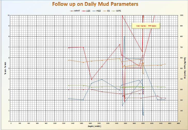
45 7. Well PRP-620A PRP-620A is a vertical well located in the north of Angola, in the Cabinda Province. It s operated by Total in the field location PAZFLOR. It has a water depth of 634 m and started drilling in June 2013 and produce from January It has a TVD of 1887 and total depth of 4590m. It has been proven to be a prosperous well where oil was found at m and m TVD and gas at m. For a much clear insight a well structure picture is illustrated in the appendix B. Figure 7- Angolan Oil fields Google picture 45
46 8. Main issues on well PRP-620A report Hole Cleaning /pit cleaning/ Hydraulics / Cleaning Pills / Hole Stability * Drilled out cement and shoe track at 2991m, working out string to reach pocket at 3001m string installing all attempt to continue drill junk at shoe and erratic pressure, attempt to establish rotation and circulation with difficulties pack off at junk string at 2988m to 2997m. Tried several attempts no success while wait for instructions, circulated at 1000 l/min and 600 l/min. Run clean out BHA but experienced same difficulties with pressure increase and junks at shoe and POOH same. Run milling BHA to bottom, attempted to mill at obstruction part of shoe without circulating to 2991m still high pressure increase. Run to bottom without circulation to 3010m, no progress every attempt pressure trapped in the string while milled to 3015m and pull out. Run 8.5" bit and drilled to m, difficult to keep drilling and pull out for cement plug#2. During scrapping time pumped 5m 3 of weighted pill (Baracarb-25 kill mud@1.50sg, circulated bottom's up observed insignificant traces of cement at shale shakers, flow checked and pulled out of hole. Loss Circulation Prevention / Curing loss Circulation No losses recorded for use of LCM during drilling, running casing and cementing job. Environment / Waste Management During drilling out cement all cement cuttings were skipped and sent to shore for further treatment. All effluents from the centrifuges lined up on active or Vortex were recovered into cutings skips and sent to shore for treatment. * 38 cuttings skip filled while drilling (23 while drilling formation, 12 while drilling shoe track, 2 while doing wiper trip) 46
47 * All formation cuttings were processed thru Verti-G then dumped to sea with a maximum of 2.29% OOC (average= %) which falls below the 5% minimum recommendable by TOTAL, for environmental. 9. WELL ISSUE ANALYSIS In well PRP-620A a present issue of Hole cleaning and hydraulic raised into a larger problem. They could not drill from 2991, 3 m to 3015 m because of the excessive WOB which supposedly damaged the casing leading to junk accumulation. This junk is usually moving so it creates a lot of difficulty for the drill bit to progress and sand was packing off around this area leading to the erratic pressure increase as reported. The total stoppage of circulation also might have influenced in the difficulty to mill out, they could have reduced it only. Usually for the milling procedure to be successful it has to be done with the controlled parameters such as 30 to 40 RPM 10 to 15 K lbf of WOB This was not observed in the report. Finally as we see in the well structure picture in the Appendix B, the minimum fracturing pressure at the shoe is 1,44 sg EMW/RT, not the same as the pressure at the top of the section which was 1,39 sg EMW/RT. So as they encountered this new pressure they should have increased the Mud weight in order to even this increase in pressure, which they did later but the problem had already escalated. 9.1 A Set of Best Practices Recommended It is better to turn the BHA as highly as possible than circulating fast (rotating the pipes improves greatly the transport of the cuttings, even at low flow rate, and a couple low Q/rotation high induces less constraint at the bore hole than high Q/rotation low) 47
48 It is better to have a thin mud but with LER high (low end rheology = Fann 6 & 3 rpm), than a viscous one with low LER. This greatly improves the carrying capacities and reduces the risk of sagging of the weighting agent (essentially for barite). As a rule of thumb, always try to maintain under down hole conditions: 1 x hole diameter drilled < Fann 6 & 3 rpm s < 1.5 x hole drilled Yield Stress = low shear rate YP = 2 x Fann 3 Fann 6 hole diameter drilled The rheology of the mud has to be optimised WHERE IT IS NECESSARY to transport the cuttings (hence under the bottom hole conditions P & T). Big pipes are better than small ones (the annulus velocity needed being lower) It is a lot better to generate small cuttings in low quantities, than big ones in high quantity. In other words, control the ROP and avoid the ROP peaks if possible, and avoid the bore hole disturbances (rock mechanics study) It is more profitable to spend some hours to clean efficiently, than spending days to try to solve a problem. So: optimise trips and cleaning circulations (frequency and procedures). Trying to minimise the length of the deviation range is a must. Consequently: optimise the well profile whenever possible. Always maximise the open section between hole and the BHA elements, in order to reduce the risks of pack off or stuck pipes events. A young cuttings bed is easier to remove than an old one. This bed must be detected ASAP thanks to the permanent monitoring of: torque, weights and tractions-sow, PUW, FRW, pressures, and quantities of cuttings returning to surface. It is essential to have a reserve in terms of traction and torque (in the event of a stuck pipe incident). Therefore: optimise the rig capacities, the mechanical characteristics of the BHA, the friction coefficient of the fluid. Good hole cleaning does not just happen, it requires a commitment from both office and the rig teams and a clear understanding of the down hole environment. 48
49 10. CONCLUSION Drilling mud plays a vital role in balancing formation pressure, lubricating and cooling bit on drilling processing. Due to its high cost and severe pollution to local environment, circulation and reutilization of drilling mud has been adopted by most of drilling companies. When pumped from downhole, the drilling mud carries massive solids that mainly consist of cuttings from crushed rocks and bentonite and barite added for better performance. Hole cleaning and hydraulics are crucial to design and drilling of vertical, directional and horizontal wells, and can limit the reach of many wells especially for wells with long horizontal reach and angle greater than 60 degrees. This work concentrated on studying field data and thereby develop models and best practices for efficient hole in general and more specifically on well PRP 620A. From the extensive research and reviews done in this present work the following conclusions have been drawn: An increase in annular velocity improves hole cleaning, regardless of the flow regime. Hole-cleaning capacity in laminar flow is improved by elevated low shear-rate viscosity and gel strengths. Turbulent flow is effective in high-angle, small diameter intervals in competent formations. Drill pipe rotation improves hole cleaning but it is more effective in viscous Mud. Hole-cleaning and well bore instability are best corrected by changing the mud weight. Due to the scarcity of reliable sources of information and the lack of proper software at the University site further performance curves and figures regarding the hole cleaning efficiency could not be developed in this thesis work. Finally, a set of best practices is given in the results section of this thesis. 49
50 10.1 Further recommendations For future projects on the matter I would recommend further studies to the models presented in this thesis, either as a thesis work or a further research work, with more sophisticated software to verify the models apart from the use of field data for verification which has been done in this work. 50
51 References 1. Chenevert, Martin E., and Reuven Hollo, TI-59 Drilling Engineering Manual, PennWell Publishing Company, Tulsa, Crammer Jr., John L. Basic Drilling Engineering Manual, PennWell Publishing Company, Tulsa, Manual of Drilling Fluids Technology, Baroid Division, N.L. Petroleum Services, Houston, Texas, Mud Facts Engineering Handbook, Milchem Incorporated, Houston, Texas, World Oil 2004 Drilling, Completion and Workover Fluids The M-I Drilling Fluids Engineering Manual, API, Rheology and Hydraulics of Oil-Well Drilling Fluids. 2006(Fifth Edition). 8. Adari, R.B., et al., Selecting Drilling Fluid Properties and Flow Rates For Effective Hole Cleaning in High-Angle and Horizontal Wells, in SPE Annual Technical Conference and Exhibition. 2000, Copyright 2000, Society of Petroleum Engineers Inc.: Dallas, Texas. 9. Walker, S. and J. Li, The Effects of Particle Size, Fluid Rheology, and Pipe Eccentricity on Cuttings Transport, in SPE/ICoTA Coiled Tubing Roundtable. 2000, Society of Petroleum Engineers: Houston, Texas. 10. Saasen, A. and G. LÃ klingholm, The Effect of Drilling Fluid Rheological Properties on Hole Cleaning, in IADC/SPE Drilling Conference. 2002, Copyright 2002, IADC/SPE Drilling Conference: Dallas, Texas. 11. Bassal, A.A., The effect of drill pipe rotation on cuttings transport in inclined wellbores. Thesis, Saasen, A., Hole Cleaning During Deviated Drilling - The Effects of Pump Rate and Rheology, in European Petroleum Conference. 1998, Society of Petroleum Engineers: The Hague, Netherlands. 13. Hassain Rabia, well engineering and construction. 2002

52 Appendices Appendix A 52

53 Appendix B 53

54 Appendix C 54

55 Appendix D 55

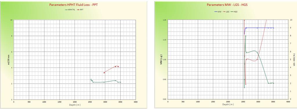
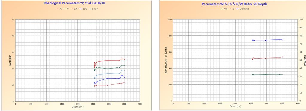
56 Appendix E Mud rheological parameters in well PRP-620A 56

57 57
58 58
59 59
60 60
W I L D W E L L C O N T R O L FLUIDS
 FLUIDS Fluids Learning Objectives You will learn about different fluids that can be used in well control. You will become familiar with the characteristics and limitations of fluids. You will learn general
W I L D W E L L C O N T R O L PRESSURE BASICS AND CONCEPTS
 PRESSURE BASICS AND CONCEPTS Pressure Basics and Concepts Learning Objectives You will be familiarized with the following basic pressure concepts: Defining pressure Hydrostatic pressure Pressure gradient
DUO-SQUEEZE H LCM Mixing Tables and Operating Procedures
 BAROID DUO-SQUEEZE H LCM Mixing Tables and Operating Procedures Prepared for: Prepared by: Submitted by: Submittal Date: All Customers Sharath Savari, Donald L. Whitfill Halliburton January 2014 1 Copyright
Operations planning for optimal hole cleaning
 Operations planning for optimal hole cleaning Rev 1.0 14 th March 2004. Technical comments? info@kingdomdrilling.co.uk Page 1 Table of contents Operations planning for optimal hole cleaning... 1 Table
WILD WELL CONTROL WARNING SIGNS OF KICKS
 WARNING SIGNS OF KICKS Warning Signs of Kicks Learning Objectives You will learn the warning signs that indicate the well may be kicking: Warning signs of kicks False kick indicators You will also learn
Float Equipment TYPE 925/926
 Type 925 Float Collar Plunger Valve Float Equipment For less demanding well conditions, such as shallower depths or lower pressures, Top- Co offers economical float equipment certified to API RP 10F category
BaraShield -664 LCM Standard Field Application Procedure
 BaraShield -664 LCM Standard Field Application Procedure Prepared for: Prepared by: Submitted by: Submittal Date: All Customers Sharath Savari, Donald L. Whitfill Halliburton March 2016 1 Copyright 2011
Chapter 5 HORIZONTAL DRILLING
 Chapter 5 HORIZONTAL DRILLING Chapter 5 How much money am I about to put on the table for a horizontal well? Did I do sufficient planning? Keys to Successful Horizontal Wells Multi-disciplined teams working
Drilling Efficiency Utilizing Coriolis Flow Technology
 Session 12: Drilling Efficiency Utilizing Coriolis Flow Technology Clement Cabanayan Emerson Process Management Abstract Continuous, accurate and reliable measurement of drilling fluid volumes and densities
Squeeze Cementing. Brett W. Williams Cementing Technical Advisor January 2016 Tulsa API Meeting
 Squeeze Cementing Brett W. Williams Cementing Technical Advisor January 2016 Tulsa API Meeting Definition Squeeze Cementing is the process of applying hydraulic pressure to force or squeeze a cement slurry
Debris Management Drilling Tools
 Debris Management Drilling Tools Protecting BHA components during well construction Remove drilling debris from the wellbore before it creates expensive problems. Debris commonly causes downhole tool failure,
APPENDIX A1 - Drilling and completion work programme
 APPENDIX A1 - Drilling and completion work programme Information about the well and drilling To the extent possible, the international system of units (SI) should be adhered to, and the drilling programme
Casing Design. Casing Design. By Dr. Khaled El-shreef
 Casing Design By Dr. Khaled El-shreef 1 Casing Design CONTENTS Function of Casing Casing Types & Tools Strength Properties Casing Specification Casing Design 2 1 RUNNING AND CEMENTING CASING Reasons for
DRILLSCENE PROACTIVE DRILLING DECISIONS
 DRILLSCENE PROACTIVE DRILLING DECISIONS RISE TO THE CHALLENGE OF REAL-TIME DRILLING CONTROL Today s oil and gas drilling operations present significant technical challenges in remote locations and increasingly
BaraBlend -665 LCM Standard Field Application Procedure
 BAROID BaraBlend -665 LCM Standard Field Application Procedure Prepared for: Prepared by: Submitted by: Submittal Date: All Customers Sharath Savari, Donald L. Whitfill Halliburton Apr 2016 1 Copyright
SIMULATION OF A RE-ENTRY WITH CASING DRILLING UNDER HPHT CONDITIONS Gabriella Federer-Kovacs 1. Introduction
 Simulation of a re-entry with casing drilling under HPHT conditions SIMULATION OF A RE-ENTRY WITH CASING DRILLING UNDER HPHT CONDITIONS Gabriella Federer-Kovacs 1. Introduction Due to the ongoing depletion
PowerDrive X6. Rotary Steerable System for high-performance drilling and accurate wellbore placement
 Rotary Steerable System for high-performance drilling and accurate wellbore placement The PowerDrive X6 RSS maintains control under the most difficult conditions, bringing the benefits of rotary steerable
DAY ONE. 2. Referring to the last question, what mud weight would be required to BALANCE normal formation pressure?
 DAY ONE 1. Normal formation pressure gradient is generally assumed to be: A..496 psi/ft B..564 psi/ft C..376 psi/ft D..465 psi/ft 2. Referring to the last question, what mud weight would be required to
Type 967 Diamond Broaching Type 968 Sidewinder reamer shoe
 Type 965 float collar Type 966 float shoe 1. GENERAL INFORMATION & RECOMMENDATIONS Type 967 Diamond Broaching Type 968 Sidewinder reamer shoe Type 969 Sidewinder reamer shoe Float Equipment Top-Co Float
float equipment OPERATING MANUAL TYPE 505/506 Float Equipment 1. INFORMATION & RECOMMENDATIONS Float Equipment
 Contents 1. GENERAL INFORMATION & RECOMMENDATIONS 1 2. INSTALLATION FLOAT EQUIPMENT 2 2.1 PRE-USE FIELD INSPECTION 2 2.2 POSITION FLOAT ON CASING STRING 3 3. RUNNING OF FLOAT EQUIPMENT 3 3.1 CIRCULATION
Chapter 8: Reservoir Mechanics
 PTRT 1472: Petroleum Data Management II Chapter 8: Reservoir Mechanics - Reservoir drives Types of Natural Gas Reservoir Fluids Natural gas is petroleum in a gaseous state, so it is always accompanied
Hydro-Mech Bridge Plug
 Manual No: 0620000303 Revision: F Approved By: Quality Engineer Date: 2014-9-9 Hydro-Mech Bridge Plug DESCRIPTION: Map Hydro-Mech Bridge Plug is hydraulically actuated and mechanically set. Compact, with
1997 Drillers Stuck pipe Handbook
 1997 Drillers Stuck pipe Handbook 1997 Guidelines & Drillers Handbook Credits written by Colin Bowes & Ray Procter with graphics by Sedco Forex Project Steering & Review Team Dave Ringrose Dick Lancaster
ECD Reduction Tool. R. K. Bansal, Brian Grayson, Jim Stanley Control Pressure Drilling & Testing
 ECD Reduction Tool R. K. Bansal, Brian Grayson, Jim Stanley Control Pressure Drilling & Testing Drilling Engineering Association, Fourth Quarter Meeting November 20, 2008 1 Presentation outline Description
Along-string pressure, temperature measurements hold revolutionary promise for downhole management
 Along-string pressure, temperature measurements hold revolutionary promise for downhole management IT S WIDELY KNOWN that the majority of stuck pipe incidents occur while pulling out of hole. If we can
Perforation Design for Well Stimulation. R. D. Barree Barree & Associates LLC
 Perforation Design for Well Stimulation R. D. Barree Barree & Associates LLC Typical Shaped Charge Primer charge Main explosive charge Case or container Detonating cord groove ¾ point of initiation Liner
Moyno ERT Power Sections. Operational Guidelines
 Moyno ERT Power Sections Operational Guidelines Moyno ERT Power Section Operational Guidelines Index 1. Introduction... 3 2. ERT Performance Graph Interpretation... 3 3. Elastomer Compression (Fit) Recommendations...
Coal Bed Methane (CBM) Permeability Testing
 Permeability Testing") Coal Bed Methane (CBM) Permeability Testing WTN Network Meeting April 28-29, 2011 ExxonMobil Exploration / Well Testing Team CBM Flow Characteristics Flow mechanism Gas desorbs when pressure drops below
Coal Bed Methane (CBM) Permeability Testing WTN Network Meeting April 28-29, 2011 ExxonMobil Exploration / Well Testing Team CBM Flow Characteristics Flow mechanism Gas desorbs when pressure drops below
Understanding pressure and pressure
 CHAPTER 1 1-1 PRESSURE BASICS Remember to think downhole. The concepts provided in this section cover the foundations for good well control. Understanding pressure and pressure relationships is important
Construction Dewatering
 Construction Dewatering Introduction The control of groundwater is one of the most common and complicated problems encountered on a construction site. Construction dewatering can become a costly issue
Extended leak off testing
 Extended leak off testing Rev: 1.0 03/01/01 Purpose To ensure minimal operational time and risk exposure to personnel, process, production and equipment. The following extended leak off test procedures
SILDRIL System Engineering Guidelines
 SILDRIL System Engineering Guidelines SILDRIL is an inhibitive system formulated with soluble silicate to achieve maximum shale inhibition. The primary shale inhibitor in the system is the Silicate, which
Worked Questions and Answers
 Worked Questions and Answers A Learning Document for prospective Candidates For the Rotary Drilling Well Control Test Programme Copyright, IWCF June 2000 Revision No.1, November 2000 IWCF 2000 page 1 of
Section 2 Multiphase Flow, Flowing Well Performance
 Section 2 Multiphase Flow, Flowing Well Performance Multiphase Vertical Flow When producing an oil or gas well, the flow of the fluids up the tubing will be in most cases be 2 phase, liquid and gas. The
OCEAN DRILLING PROGRAM
 BIH OCEAN DRILLING PROGRAM www.oceandrilling.org Scientifi c Application Packers A packer is an inflatable rubber element that inflates to seal the annular space between the drill string and the borehole
PRODUCTION AND OPERATIONAL ISSUES
 PRODUCTION AND OPERATIONAL ISSUES Dr. Ebrahim Fathi Petroleum and Natural Gas Engineering Department West Virginia University Audience and Date March 2, 2016 Summary Production and Operational Issues Shale
The Lean Profile: A step change in dnlling performance
 European Geothermal Conference Basel 99 September 28-30, 1999 - Basel, Switzerland. Proceedings, Volume 2 The Lean Profile: A step change in dnlling performance by A. Calderoni, A. Ligrone & C. Molaschi
Open water, Riserless Drilling fundamentals
 Open water, Riserless Drilling fundamentals By Peter Aird Synopsis This document illustrates open water drilling operations, to emphasise operational and engineering considerations that need to be combined
FREQUENTLY ASKED QUESTIONS
 What are some applications in which you ve successfully used this product? New Completions - Stage by Stage Diversion Between Frac plugs for Intra-Stage Diversion Replace Frac Plugs with Perf PODs - Full
Study Guide IADC WellSharp Driller and Supervisor
 Times to Flow Check: Before pulling out of the hole Before pulling BHA into the BOP When bit is pulled into the casing Increase in cuttings at shakers with same ROP On connections Upon abnormal trip tank
Step-Rate Formation Integrity Test Method for Geothermal Wells
 GRC Transactions, Vol. 41, 2017 Step-Rate Formation Integrity Test Method for Geothermal Wells William M. Rickard, Ozgur Balamir and Ernesto Rivas Geothermal Resource Group, Inc. services@geothermalresourcegroup.com
ARTICLE. Overcome casing integrity issues in your plug-and-perf operations
 ARTICLE Overcome casing integrity issues in your plug-and-perf operations CONTENT A challenge to plug-and-perf success 3 Causes of casing restrictions 9 How extended-range frac plugs keep operations moving
R.K. Bansal, Weatherford; P.A. Bern, BP Exploration; Rick Todd, Weatherford; R.V. Baker, BP America; Tom Bailey, Weatherford
 AADE-07-NTCE-69 A Downhole Tool for Reducing ECD R.K. Bansal, Weatherford; P.A. Bern, BP Exploration; Rick Todd, Weatherford; R.V. Baker, BP America; Tom Bailey, Weatherford Copyright 2007, AADE This paper
CTB3365x Introduction to Water Treatment
 CTB3365x Introduction to Water Treatment D4b Aeration Doris van Halem Did you know that there are not just gasses in your glass of sparkling coke, but also in the tap water you drink? Welcome to the water
DB Bridge Plug. Features. Benefits. Applications
 DB Bridge Plug The WELLFIRST Premium Cast Iron Bridge Plug designed to run on electric line. Rated between 2000-10000-psi differential, and 300 F from above and below. Features Field Proven Design Constructed
OPERATING MANUAL DOUBLE ACTING DRILLING INTENSIFIER HYDRAULIC TYPE
 Page 1 of 8 OPERATING MANUAL DOUBLE ACTING DRILLING INTENSIFIER HYDRAULIC TYPE Size Series 6.50" 478 Reviewed And Approved By: Signature: Initials: Date: Page 2 of 8 Section OPERATING MANUAL DOUBLE ACTING
PTRT 1471: Exploration and Production I. Chapter 6: Drilling and Well Completion
 PTRT 1471: Exploration and Production I Chapter 6: Drilling and Well Completion Well Planning Drilling is a major investment (over $100m for offshore) Planning is aimed at maximizing investment Wells are
RULES OF THE OIL AND GAS PROGRAM DIVISION OF WATER RESOURCES CHAPTER DRILLING WELLS TABLE OF CONTENTS
 RULES OF THE OIL AND GAS PROGRAM DIVISION OF WATER RESOURCES CHAPTER 0400-52-06 DRILLING WELLS TABLE OF CONTENTS 0400-52-06-.01 Drilling Equipment 0400-52-06-.03 Casingheads 0400-52-06-.02 Blowout Prevention
Hydraulic Optimization Worksheet for MS Excel All Versions subsequent to 5.0
 Hydraulic Optimization Worksheet for MS Excel All Versions subsequent to 5.0 1. Introduction. 2. Data Input. Header. Bit Information. Mud Information. Casing Program. P.D.M./Turbine. Drill String Design.
Why Do Not Disturb Is a Safety Message for Well Integrity
 Why Do Not Disturb Is a Safety Message for Well Integrity Presented at the Practical Well Integrity Conference 9-10 December, 2014 in Houston By Ron Sweatman, Principal Advisor, Reservoir Development Services,
SCORPION HIGH-QUALITY, FULLY COMPOSITE PLUGS
 SCORPION HIGH-QUALITY, FULLY COMPOSITE PLUGS A DIFFERENT KIND OF ENERGY COMPANY Nine Energy Service isn t your typical oilfield services company. Our success stems from a culture driven by performance
Inflatable Packer Single & Double. Single & Double Packer Dimension. Wireline Packer. Water Testing Packer (WTP) Packer
 Packer") Inflatable Packer Single & Double Single & Double Packer Dimension Wireline Packer Water Testing Packer (WTP) Packer Packer Working Pressure & Depth Chart Packer Water Hand Pump Packer Air Driven Pump
Inflatable Packer Single & Double Single & Double Packer Dimension Wireline Packer Water Testing Packer (WTP) Packer Packer Working Pressure & Depth Chart Packer Water Hand Pump Packer Air Driven Pump
A hose layline contains important information for specifying the replacement assembly: manufacturer, hose trade name, working pressure and hose ID.
 CONTENTS Introduction Pressure Pressure Drop Temperature Rating Bend Radius Conclusion Additional Information SIDEBAR: Understanding Hydraulic Hose Reinforcement INTRODUCTION Hydraulic hose has a finite
SURFACE CASING SELECTION FOR COLLAPSE, BURST AND AXIAL DESIGN FACTOR LOADS EXERCISE
 SURFACE CASING SELECTION FOR COLLAPSE, BURST AND AXIAL DESIGN FACTOR LOADS EXERCISE Instructions Use the example well data from this document or the powerpoint notes handout to complete the following graphs.
Restoring Fluid Flow in Tubing Strings
 Restoring Fluid Flow in Tubing Strings Andrew Roth, Product Manager Fike Corporation Fike Hydraulic Tubing Drains (HTD) for use with deep hole drilling tools, downhole devices and other oil and off shore
Bridge Plugs, Ball Drop & Caged Ball Plugs For Zone Isolation
 Bridge Plugs, Ball Drop & Caged Ball Plugs For Zone Isolation ADVANTAGE composite bridge plug, caged ball and ball drop (flow thru) frac plug provide a means to isolate multiple zones during high pressure
HydroPull. Extended-Reach Tool. Applications
 Extended-Reach Tool HydroPull This tool incorporates a cycling valve that momentarily interrupts the flow to create water-hammer pressure pulses inside coiled or jointed tubing used in horizontal well
SYSTEMIC APPROACH TO MINIMIZE STUCK PIPE INCIDENTS IN OIL WELLS
 Journal of Al Azhar University Engineering Sector Vol. 11, No. 38, January, 2016, 255-264 SYSTEMIC APPROACH TO MINIMIZE STUCK PIPE INCIDENTS IN OIL WELLS H. Abd Elsalam 1, Y. ElNady 2, T. Elfakharany 2
North American sealing solutions Bridge Plug Ball Drop Frac Plug Caged Ball Frac Plug
 North American sealing solutions Bridge Plug Ball Drop Frac Plug Caged Ball Frac Plug The North American Sealing Solutions composite bridge plug, caged ball and ball drop (flow thru) frac plug provide
Cased-Hole Logging Environment
 Cased-Hole Logging Environment 2 Planning a Production Logging Job Planning is an important part of a production logging job. Frequently these jobs can only be done in safety during daylight. Thus, the
Testing Services Overview
 2 Jet Research Center JRC Jet Research Center Perforating Center of Excellence Testing Services Overview API RP19B Testing Advanced Testing Operational Testing API RP19B Testing The American Petroleum
FORMATION TESTER MOBILITY. Lachlan Finlayson, Chief Petrophysicist Petrofac Engineering & Production Services Engineering Services Consultancy
 FORMATION TESTER MOBILITY Lachlan Finlayson, Chief Petrophysicist Petrofac Engineering & Production Services Engineering Services Consultancy 1 Introduction Petrofac Formation Testers Pretest Procedure
Perforating Center of Excellence TESTING SERVICES OVERVIEW
 Perforating Center of Excellence TESTING SERVICES OVERVIEW Jet Research Center (JRC) is the leader in energetic research and testing for the oil and gas industry. Since introducing jet perforators for
Representing EXAMINERS REPORT AND PROPOSAL FOR DECISION STATEMENT OF THE CASE
 OIL AND GAS DOCKET NO. 03-0231502 THE APPLICATION OF JOHNSON SANFORD OPERATING COMPANY TO AMEND ITS PERMIT TO DISPOSE OF OIL AND GAS WASTE BY INJECTION INTO A POROUS FORMATION PRODUCTIVE OF OIL OR GAS,
IMPROVING PLANT AERATION USING GAS INFUSION TECHNOLOGY
 IMPROVING PLANT AERATION USING GAS INFUSION TECHNOLOGY AERATION IN WASTEWATER Municipal sewer collection systems-odor Mgmt. Lift and transfer stations Lagoons / Retention Ponds BOD / COD treatment Enhanced
Bioreactor System ERT 314. Sidang /2011
 Bioreactor System ERT 314 Sidang 1 2010/2011 Chapter 2:Types of Bioreactors Week 4 Flow Patterns in Agitated Tanks The flow pattern in an agitated tank depends on the impeller design, the properties of
Well Testing Plan. New York Marginal Well Study. Introduction. I. Tests to be Conducted. II. Testing Procedures
 Well Testing Plan New York Marginal Well Study Introduction The Independent Oil and Gas Association of New York, Inc. (IOGANY) has been awarded funding for a Marginal Well Testing Program from the New
Advanced Applications of Wireline Cased-Hole Formation Testers. Adriaan Gisolf, Vladislav Achourov, Mario Ardila, Schlumberger
 Advanced Applications of Wireline Cased-Hole Formation Testers Adriaan Gisolf, Vladislav Achourov, Mario Ardila, Schlumberger Agenda Introduction to Cased Hole Formation tester Tool specifications Applications
6-3/4 DUAL PORTED PBL BYPASS SYSTEM (Applicable to sizes 6-1/4 & 6-1/2 also)
") RECEIVING PBL AT RIG SITE TITLE: Operating Instructions for -3/4 PBL -3/4 DUAL PORTED PBL BYPASS SYSTEM (Applicable to sizes -1/4 & -1/2 also) OPERATING INSTRUCTIONS 1. On receipt of PBL Bypass Tools at
RECEIVING PBL AT RIG SITE TITLE: Operating Instructions for -3/4 PBL -3/4 DUAL PORTED PBL BYPASS SYSTEM (Applicable to sizes -1/4 & -1/2 also) OPERATING INSTRUCTIONS 1. On receipt of PBL Bypass Tools at
Dilution-Based Dual Gradient Well Control. Presented at the 2011 IADC Dual Gradient Workshop, 5 May 2011 by Paul Boudreau, Dual Gradient Systems LLC
 Dilution-Based Dual Gradient Well Control Presented at the 2011 IADC Dual Gradient Workshop, 5 May 2011 by Paul Boudreau, Dual Gradient Systems LLC In this very short presentation, we will Review Dilution-based
WELL SCAVENGER. Versatile wellbore clean-up tool for the most demanding operations
 WELL SCAVENGER Versatile wellbore clean-up tool for the most demanding operations WELL SCAVENGER: A versatile wellbore cleanup tool for flowrestricted applications The inability to recover wellbore debris
For Establishing and Maintaining Your Spa using PROtech Spa Chemicals
 Spa Care For Establishing and Maintaining Your Spa using PROtech Spa Chemicals QUICK START Add water up to the level recommended by the manufacturer of your spa and let the pump circulate for at least
RIH intermediate section casing in Bazian-1 exploration oil well
 Energy and Sustainability V 559 RIH intermediate section casing in Bazian-1 exploration oil well A. K. Darwesh Petroleum Engineering Department, Engineering Faculty, Koya University, Kurdistan Abstract
Blowout during Workover Operation A case study Narration by: Tarsem Singh & Arvind Jain, OISD
 1. Introduction An incident of gas leakage from a well took place during workover operations. Subsequently, the gas caught fire on the fourth day in which twelve persons were injured. Two contract workers,
Lecture 8&9: Construction Dewatering
 Arab Academy for Science, Technology & Maritime Transport Colleague of Engineering & Technology Construction & Building Engineering CB 523 Methods and Equipment for Construction 1 Lecture 8&9: Construction
AADE 01-NC-HO-08. Copyright 2001 AADE National Drilling Technical Conference
 AADE 01-NC-HO-08 Planning and Field Validation of Annular Pressure Predictions Gregory Mullen, Chakravarthy Singamsetty, William Dye, Baker Hughes, INTEQ Drilling Fluids, Danny Ledet, Andrew Rawicki, Todd
New generation of solid expandable liners help give operators a jump on trouble zones
 New generation of solid expandable liners help give operators a jump on trouble zones By Pat York, Weatherford SINCE SOLID EXPANDABLE technology has gained credibility as an effective contingency option,
IWCF Equipment Sample Questions (Combination of Surface and Subsea Stack)
") IWCF Equipment Sample Questions (Combination of Surface and Subsea Stack) 1. Given the volumes below, how much hydraulic fluid will be required to carry out the following operations (no safety margin)?
IWCF Equipment Sample Questions (Combination of Surface and Subsea Stack) 1. Given the volumes below, how much hydraulic fluid will be required to carry out the following operations (no safety margin)?
Permeability. Darcy's Law
 Permeability Permeability is a property of the porous medium that measures the capacity and ability of the formation to transmit fluids. The rock permeability, k, is a very important rock property because
1 Scope... 2 Functions of cementing float equipment... 3 Definitions... 4 Calibration... 5 Test Categories... 6 General...
 American Petroleum Institute Contents Page 1 Scope... 2 Functions of cementing float equipment... 3 Definitions... 4 Calibration... 5 Test Categories... 6 General... 7 Apparatus and Materials... 8 High-temperature/high-pressure
Rig Math. Page 1.
 Page 1 The Calculator and Main Keyboard Display Numerical 10-key pad used for entering numerical values Trigonometric Functions These keys will be used where wellbore angle is an issue These are the keys
Coal and Water Protection. PADEP: Well Plugging & Subsurface Activities Division Bureau of Oil and Gas Planning & Program Management
 Coal and Water Protection PADEP: Well Plugging & Subsurface Activities Division Bureau of Oil and Gas Planning & Program Management Review of Applicable Regulations & Laws Coal protective casing: A string
Drilling fluid rheology at challenging drilling conditions an experimental study using a 1000 bar pressure cell
 Drilling fluid rheology at challenging drilling conditions an experimental study using a 1000 bar pressure cell Anja Torsvik, Velaug Myrseth, and Harald Linga SINTEF Petroleum, Department of Drilling and
TECHNICAL BENEFITS OF CJS / RAISE HSP. Technical Advantages
 TECHNICAL BENEFITS OF CJS / RAISE HSP Technical Advantages The HSP is designed for low- to mid- volume applications at flow rates of 1 cubic meter to 30 c. m per day. The benefits are in the details. The
Inflatable Packers for Grouting 11/10/00
 Introduction Inflatable Packers for Grouting 11/10/00 Inflatable packers are frequently used for grout injection in geotechnical applications for structural reinforcement and/or water-proofing of foundations,
Designing a Model Rocket
 Designing a Model Rocket Design Components In the following pages we are going to look at the design requirements for a stable single stage model rocket. From the diagram here you can see that the rocket
Practice Exam IADC WellSharp Driller and Supervisor
 Workover & Completion Day 4 1. In a workover operation of a shut in well a Lubricator is being used together with a Wireline BOP / Wireline Valve. Which Barrier is classified as the Primary Barrier? A.
Perforating Options Currently Available in Horizontal Shale Oil and Gas Wells. Kerry Daly, Global BD Manager- DST TCP
 MENAPS 2013 Perforating Options Currently Available in Horizontal Shale Oil and Gas Wells Kerry Daly, Global BD Manager- DST TCP MENAPS 13-17 WELL FLOW MANAGEMENT TM Scope/ Contents: MENAPS 13-17 Study
Mix and Flow of Matter Unit Test. For each of the following hazardous products match the correct WHMIS symbol
 /40 Student Name Class Section 1.1 WHMIS For each of the following hazardous products match the correct WHMIS symbol 1 Flammable A. 2 Corrosive B. 3 Dangerously Reactive C. Section 1.2 The Many Uses of
COGCC OPERATOR GUIDANCE MECHANICAL INTEGRITY TEST GUIDANCE: PRACTICES AND PROCEDURES
 COGCC OPERATOR GUIDANCE MECHANICAL INTEGRITY TEST GUIDANCE: PRACTICES AND PROCEDURES DOCUMENT CONTROL: Created Date: May 06, 2013 Last Updated Date: September 15, 2015 Last Updated By: Stuart Ellsworth
Air and Gas Drilling
 Air and Gas Drilling Air and Gas Drilling It is a technique in which the more common drilling fluids, (water or mud) are replaced by highly compressible Air or Natural gas. But Compressibility makes pressure
A Novel Approach to Capitalize WITSML Data in Geospatial Platform for Realtime Monitoring and Risk Assessment
 A Novel Approach to Capitalize WITSML Data in Geospatial Platform for Realtime Monitoring and Risk Assessment Dr. Sethupathi Arumugam PhD Principal Consultant Biswa Ranjan Patra Principal Consultant Shebi
2-7/8 TRIPLE PORTED PBL BYPASS SYSTEM
 RECEIVING PBL AT RIG SITE TITLE: Operating Instructions for 2-7/8 Triple Port PBL 1-10-201 2-7/8 TRIPLE PORTED PBL BYPASS SYSTEM OPERATING INSTRUCTIONS 1. On receipt of PBL Bypass Tools at Rig site, the
DFT Valves. Selecting Control Valves
 DFT Valves Selecting Control Valves Evaluating Process Conditions in Control Valve Selection A one-size-fits-all approach is not the best way to go about choosing the proper control valve for a particular
APPLYING VARIABLE SPEED PRESSURE LIMITING CONTROL DRIVER FIRE PUMPS. SEC Project No
 APPLYING VARIABLE SPEED PRESSURE LIMITING CONTROL DRIVER FIRE PUMPS SEC Project No. 1803007-000 November 20, 2006 TABLE OF CONTENTS I. ABSTRACT...1 II. INTRODUCTION...1 III. HISTORY...2 IV. VARIABLE SPEED
BLACK HILLS PLATEAU PRODUCTION COMPANY
 BLACK HILLS PLATEAU PRODUCTION COMPANY DRILLING PROGRAM Homer Deep Unit 9 11CH SHL: 300 FNL, 200 FWL, NWNW Sect. 9 T8S R98W BHL: 1350 FSL, 2100 FEL NWSE Sect. 15 T8S R98W Garfield & Mesa Counties, Colorado
Fundamentals Of Petroleum Engineering PRODUCTION
 Fundamentals Of Petroleum Engineering PRODUCTION Mohd Fauzi Hamid Wan Rosli Wan Sulaiman Department of Petroleum Engineering Faculty of Petroleum & Renewable Engineering Universiti Technologi Malaysia
Coiled Tubing string Fatigue Management in High Pressure Milling Operation- Case Study
 Coiled Tubing string Fatigue Management in High Pressure Milling Operation- Case Study Abstract: Paper Presenter: Ebrahim Rabbani 1 e.rabbani@mehranservices.com Ebrahim Rabbani, Danial Davoodi 2, Fatemeh
EDUCTOR. principle of operation
 EDUCTOR principle of operation condensate and mixing eductor s are designed to mix two liquids intimately in various proportions in operations where the pressure liquid is the greater proportion of the
GEOTHERMAL WELL COMPLETION TESTS
 GEOTHERMAL WELL COMPLETION TESTS Hagen Hole Geothermal Consultants NZ Ltd., Birkenhead, Auckland, New Zealand. ABSTRACT This paper reviews the measurements that are typically made in a well immediately