Portable Pressurized Infusion Pump. and. Air Compressor. Operating and Service Manual
|
|
|
- Carol May
- 5 years ago
- Views:
Transcription
1 Portable Pressurized Infusion Pump and Air Compressor Operating and Service Manual Model # s: PIP-6-4SS PIP-6-6SS PIP-6-8SS PIP-6-10SS PIP-6-12SS PIP-6-14SS PIP-6-16SS PIP-6-18SS PIP-6-20SS PIP-6-22SS PIP-6-24SS P4-F-210 P4-F Mui Scientific 145 Traders Blvd. E., Unit #33-34 Mississauga, Ontario, Canada L4Z 3L3 Tel: (905) Toll Free: (800) Fax: (905) mail@muiscientific.com Website: EC REP Advena Ltd. Pure Offices, Plato Close, Warwick, CV34 6WE, United Kingdom Manual P4-J-201, May 11, 2016 Federal law (U.S.) restricts the sale of this device to, or by the order of physician.


2 READ ENTIRE MANUAL BEFORE OPERATING THIS PUMP 2
3 Table of Contents SECTION 1 INTRODUCTION 1.1 INTRODUCTION FIGURES... 5 SECTION 2 DESCRIPTION OF PUMP 2.1 PHYSICAL DESCRIPTION GENERAL REQUIREMENTS... 8 SECTION 3 INITIAL INSTALLATION 3.1 INITIAL UNPACKING ASSEMBLY OF PUMP... 9 SECTION 4 PREPARATION PROCEDURES 4.1 FILLING THE WATER RESERVOIR CONNECTING AIR COMPRESSOR ADJUSTING WATER RESERVOIR PRESSURE FILLING PUMP AND TRANSDUCERS WITH WATER CALIBRATION OF RECORDING SYSTEM FUNCTIONAL CHECK- PINCH TEST NORMAL OPERATION BEFORE AND DURING THE STUDY POST STUDY: DAILY BLOW-DRY SHUT-DOWN PROCEDURE SECTION 5 TROUBLESHOOTING 5.1 FUNCTIONAL TROUBLESHOOTING WITH THE PINCH TEST CALCULATION OF PRESSURE RISE RATE SECTION 6 SERVICE: MAINTENANCE 6.1 OPTION A: STERILIZATION OF PUMP PARTS OPTION B: HIGH-LEVEL DISINFECTION CARE AND CLEANING OF THE PUMP SECTION 7 AIR COMPRESSOR 7.1 AIR COMPRESSOR FIGURES DRYING THE DESICCANT SECTION 8 PUMP PARTS LIST 8.1 PUMP PARTS LIST
4 Section 1 Introduction 1.1 INTRODUCTION This Portable Pressurized Infusion Pump is part of the motility system used for intraluminal manometric studies of the gastrointestinal tract, such as pressure measurement of muscular contractions or resting tone inside the esophagus, stomach, bile duct, small intestine, anus, rectum, or colon. Other components of this system include a set of pressure transducers, a motility catheter, and a computerized data processing system or a chart recorder. The pump uses regulated compressed air to deliver sterilized water through very small bore tubing in the resistors to the motility catheter. The pressurized water from each resistor is connected to a pressure transducer and then passes through one lumen of the multi-lumen catheter to that lumen s single opening into the esophagus of the patient. The pressure changes in the esophagus are transmitted through this fluid path back to the externally mounted transducer; i.e. the water serves as a pressure - transmission medium. Each lumen of the motility catheter is connected to its own pressure transducer and all the pressure transducers are connected to a computerized recording system or a strip chart recorder. The pressure profile of the multi-channel tracing provides useful diagnostic data for evaluation of the normal or abnormal motor function of the gastrointestinal tract. Similar applications include pressure measurements for oropharygeal, esophageal, stomach, intestinal, colonic, anorectal and biliary motility studies. This pump is designed to operate at a constant pressure rather than at a constant flow rate. It maintains a pre-set hydraulic pressure (5-15 psi) at the water reservoir regardless of the flow. At 15 psi (776 mm Hg) the pump provides a high static hydraulic pressure background to ensure a high pressure rise rate as well as recording accuracy and repeatability. It can record fast pressure changes such as in the upper esophageal sphincter. The small bore of the resistor tube also ensures a very low infusion rate. During a motility study, the actual flow rate varies due to the varying amount of obstruction caused by muscle contractions. The pressure rise rate of the pump, measured as pressure change per unit of time (i.e. mm Hg/sec or cm H2O/sec), varies directly with the water reservoir pressure. A higher water reservoir pressure will result in a higher pressure rise rate but also a higher flow rate. To achieve measurement accuracy, the pressure rise rate of the recording system must exceed the actual physiological rise rate of the organ. The upper esophageal sphincter has the highest muscular contraction rate of the gastrointestinal tract. A study of this organ requires the highest pressure rise rate of the recording system, 400 mm Hg/sec. The recommended water reservoir pressure of 15 psi (pounds per square inch) will achieve a pressure rise rate of 400 mm Hg/sec. The main purpose of reducing the water reservoir pressure from 15 to 5 psi is to reduce the infusion rate from 0.6 to 0.2 ml/min. The lower water reservoir pressure and lower pressure rise rate still permit reliable measurement accuracy on those organs that have a lower physiological contraction rate. The pump allows the operator to change the water reservoir pressure for different physiological applications in order to optimize the pressure rise rate and flow rate. An infusion rate table (Table 1, Section 4.3) is provided to enable an estimate of the total volume of water infused into the patient in a given period of time. 4


5 1.2 FIGURES Figure 1 Front View 5
6 Figure 2 Side View 6
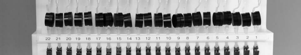
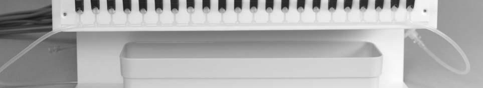
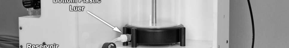
7 Section 2 Description of Pump 2.1 PHYSICAL DESCRIPTION The black hose from the air compressor is connected to the red quick-connect on the right side of the pump. The pressurized air can be regulated with the manually adjustable pressure regulator. The air compressor pressurizes the water reservoir, which delivers pressurized water to a manifold, and then connects to a set of compact resistors. The compact resistors connect to the bottom of the transducers, located on the top of the pump, which connects to the multi-lumen motility catheter. The pressurized air is regulated with a manually adjustable regulator. This sets the final pressure in the water reservoir. The Supply Pressure gauge (right side) shows the pressure from the external air supply. The Driving Pressure gauge (left side) shows the pressure in the water reservoir. (Refer to Figures 1 and 2 in Section 1.2). The water reservoir is removable, simply resting between the black pegs, which sits atop the control box. The chamber float acts as a barrier to minimize air absorption into the water. The lid of the water reservoir is removable to facilitate filling and cleaning. The blue pinch clamp (or 2-way stopcock) on the Reservoir Outflow Control Device at the bottom of the water reservoir provides the main on/off control of the water flow to the manifold. The outlet of the manifold is connected to the compact resistors which connect to the bottom of the transducers. The 2-way stopcock at the bottom of the transducers function as individual shut-offs for each of the transducers. The pigtails of the motility catheter are connected to the top of each transducer (Refer to Figure 2 in Section 1.2). 7
8 2.2 GENERAL REQUIREMENTS CAUTION: This pump must only be used in a medical setting under the medical supervision of a physician who has received professional training in gastrointestinal manometry. The pump should be positioned at approximately the same height as the patient s bed. The height of the transducers should be level with the height of the patient s stomach. This will minimize the hydrostatic pressure artifact on the transducer and on the recording. CAUTION: No electrical equipment should be located beneath the pump. Some water from the catheter is likely to drip down during the procedure. A danger of electric shock could result. Use only sterilized irrigation or distilled water in the water reservoir. Never use tap water as it contains minerals which can cause blockages in tubing and/or can support bacterial growth. Electrical requirements for Air Compressor Unit (if included): (a) 115 Volt Model: A grounded, hospital grade, 115 Volt, 60 Hz, 15A electrical outlet is required. The pump is rated at 2A. Hospital grade power cord with IEC plug is included. (b) 220 Volt Model: A grounded, hospital grade, 220 Volt, 50 Hz electrical outlet is required. The pump is rated at 2A. Hospital grade power cord with female IEC plug is required. CAUTION: Duty cycle: Maximum 5 minutes out of 120 minutes. The inlet pressure rating: 117kPa 373kPa. 8
9 Section 3 Initial Installation 3.1 INITIAL UNPACKING Remove any remaining packing material. Place the main pump assembly on a table. Unpack the following: Calibration rod (with 2 tubes and 2 thumb screws) Water collection tray Compact resistors Water reservoir Reservoir outflow control device 3.2 ASSEMBLY OF PUMP Attach the accessories in the following order (refer to Figures 1 & 2 in Section 1.2): Place the calibration rod against the left back of the pump and secure the rod to the pump using the 2 thumb screws provided. Slide the calibration tubes onto the upper and lower holders on the rod. Place the water collection tray in the left bottom tray holder. Remove the channel number label strip from the top of each transducer bar by unscrewing the 4 thumb screws on top. Slide a transducer downward into each transducer holder, folding the cord upwards behind the transducer to fit in the groove of the transducer bar and hang over the top into the cable box. Secure transducers in place by replacing the channel number label strip and securing with the thumb screws on top. Connect the cord from each transducer to the cables that leads to your computer motility system. Attach the compact resistors to the bottom of the transducers (female luer) and to the top of the water manifold (male luer). Place the water reservoir onto the top housing of the pump so the bottom plastic luer sits in between the two pegs on the left. Connect the reservoir outflow control device from the connector at the bottom of the water reservoir to the right end of the water manifold. Connect the black hose from the pressure regulator to the metal quick-connect on the lid of the water reservoir. Push the two metal fittings together until they snap into the latched position. Connect the black compressor hose to the red quick-connect on the right side of the pump. Push the two metal fittings together until they snap into the latched position. 9
10 Section 4 Preparation Procedures 4.1 FILLING THE WATER RESERVOIR Ensure that the blue pinch clamp (or the 2-way stopcock) on the reservoir outflow control device is in the OFF position. Ensure the 2-way stopcocks below the transducers are open. Unscrew the knob of the water reservoir and remove the lid and round float by tipping the water reservoir on its side. Ensure that the inside of the water reservoir is clean. Fill three-quarters full with sterilized irrigation or sterilized distilled water only. Replace the float in the water reservoir to avoid any bubbles being trapped under the float. CAUTION: Never use the pump without the float in the water reservoir. Air bubbles will form at the transducer and will reduce the pressure rise rate and the accuracy of measurement. Replace the lid and screw the knob back on and tighten securely. Ensure the bottom plastic luer located at the bottom of the water reservoir is connected. Ensure the top metal quick-connect located on the lid of the water reservoir is connected by pushing the two metal fittings together until they snap into the latched position. 4.2 CONNECTING COMPRESSOR Attach the black extension tube from the compressor to the red quick-connect on the right side of the pump. Push the two metal fittings together until they snap into the latched position. (NOTE: pump will not be pressurized until air compressor is turned ON)
11 4.3 ADJUSTING WATER RESERVOIR PRESSURE To select water reservoir pressure for optimal recording accuracy of pressure rise rate for your recording site or organ, refer to Table 1 and adjust the water reservoir pressure accordingly. CAUTION: Do not set water reservoir pressure higher than 15 psi. Patient will receive excessive water. Table 1. Water Reservoir Pressure Selection vs Infusion Rate/Pressure Rise Rate RECORDING APPROXIMATE RECOMMENDED MINIMUM SITE INFUSION WATER RESERVOIR PRESSURE RISE (ORGAN) RATE PRESSURE RATE WITH COMPACT pound/square inch AT CATHETER RESISTORS (kpa) OPENING ml/min mm Hg/sec UES (103) 400 Esophagus (103) 400 Stomach (103) 400 Small Bowel (35) 60 Bile Duct (35) 60 Colon (35) 60 Table 2. Pressure Conversion Chart Psi cm of H 2 O mm of Hg kpa
12 4.4 FILLING PUMP AND TRANSDUCERS WITH WATER Ensure the water collection tray is placed under the transducers to catch any water that may drip out. Ensure the blue pinch clamp (or 2-way stopcock) on the reservoir outflow control device is in the OFF position. Ensure all 2-way stopcocks below the transducers are open. After the water reservoir pressure has been adjusted to the desired level (usually 15 psi), open the blue pinch clamp (or 2-way stopcock) on the reservoir outflow control device leading into the right side of the water manifold. Allow 2-3 minutes for the water pressure to purge any air inside the compact resistors. Ensure the water is flowing out of the top of the transducers and no trapped air bubbles are in the transducers. Attach the motility catheter to transducers. Fill the catheter with water and flush out any remaining air bubbles. The pump system is now filled with water and ready for a functional check. 4.5 CALIBRATION OF RECORDING SYSTEM Refer to the manufacturer s instructions for your computerized data processing system. Follow the recommended calibration procedure. Use of Hydrostatic Calibration System (0-50 cm H 2 O or 0-68 cm H 2 O) With pump ON and water dripping, slide catheter into the bottom calibration tube. The bottom calibration tube is fixed to the same height as the transducers. This position simulates 0 cmh 2 O or 0 mmhg pressure. Select low calibration on computer or adjust baseline on recorder to 0 cmh 2 O or 0 mmhg position for each channel. Slide catheter into the top calibration tube. This position generates 68 cmh 2 O pressure or 50 mmhg (or 50cm H 2 O). Select high calibration on computer, or adjust the recorder to 68 cmh 2 0 or 50 mmhg (or 50cm H 2 O) for each channel. The pump is now calibrated and in stand-by mode ready for a study. 12
13 4.6 FUNCTIONAL CHECK- PINCH TEST It is recommended that this pinch test be performed routinely at the beginning of each motility study. This test confirms that the entire system is functioning properly, including the pump, the transducers, and the recording system, and gives a permanent record of the functional performance of the system. This pinch test is also useful during a study whenever the clinical tracing is abnormally inactive and the performance of the system is in question. Run the recording program as you normally would for a motility study. Set the recording system pressure amplitude as you would for a study. Firmly pinch the motility catheter for several seconds at a point immediately above the transducer and release it. The pressure tracing should respond immediately with a virtually vertical rise to the full-scale pressure amplitude as set. This response confirms that the entire system is functioning properly, with no leakage or major trapped air bubbles in the system. If poor response, troubleshoot before beginning study. Refer to Section 5.1 Functional Troubleshooting with the Pinch Test, for detailed explanations of unsatisfactory pressure tracings, and to Section 5.2 for Calculation of Pressure Rise Rate. Repeat this test for all channels. The pump is now in standby mode ready for calibration. 4.7 NORMAL OPERATION BEFORE AND DURING THE STUDY Check that there is sufficient water in the reservoir to complete the study. Refill the water reservoir if necessary. The Driving Pressure gauge should be set at the desired level (usually 15 psi). The motility catheter should be firmly attached to the stopcocks on the top of the transducers and all air bubbles should have been flushed out. Calibrate the recording system if necessary (Refer to Section 4.5 Calibration of Recording System, and see instructions from the manufacturer of the computer system). Make sure that all the tracings are at 0 pressure (baseline position). Run the computer as for a motility study. Set the baseline tracing to 0. This establishes the true hydrostatic baseline of 0 pressure. With the pump ON, all tracings should show an increase from the baseline of 2-10 mm Hg. This is known as the infusion artifact. It is caused by friction and restriction of the water flow passing through the catheter. If an abnormally high infusion artifact occurs, blockage may have occurred within the motility catheter. (Refer to Figure 3 below). Set the infusion baseline tracing to 0 again. This is the infusion baseline, the baseline pressure with the infusion artifact removed. This is the baseline to be used for the study. Pinch Test: Pinch the motility catheter immediately above the transducer and observe a 13
14 sharp rise in the tracing. Repeat the pinch test for all channels. If the tracing does not rise sharply full-scale (refer to Figure 4 below), the pump and/or computerized recording system are not functioning properly. Troubleshoot the problem before proceeding with the study (Section 5.1 Functional Troubleshooting with the Pinch Test). If the tracings are acceptable, the motility catheter can be placed into the holding tray directly below the water manifold until the patient is ready for insertion, or it can be immediately inserted into the patient. You can repeat the pinch test again, or start the motility procedure according to your protocol. Figure 3 - Infusion Artifact Figure 4 Pinch Test: Normal and Slow Pressure Rise Rate 14
15 4.8 POST STUDY: DAILY BLOW-DRY SHUT-DOWN PROCEDURE Release all pressure in the pump system by disconnecting and reconnecting the metal quick-connect on the water reservoir lid several times until the pressure in both gauges on the control box (and the gauge on the compressor, if included) drop to zero. Empty all the water in the water reservoir. Reconnect the empty water reservoir and pressurize by reconnecting the metal quick-connect on the water reservoir lid. Open all valves and stopcocks. Flush the whole system with air for 5 minutes or until no more water is dripping out of the transducers. Disconnect and reconnect the water reservoir metal quick-connect several times and depressurize the pump system. Remove empty water reservoir. Store dry with lid off. Store pump system dry with all stopcocks and valves open. CAUTION: Do not leave any water in the pump system or water reservoir overnight. Retained water in the pump system may cause the growth of bacteria to unacceptable potable water standards. SERVICE MAINTENANCE According to clinical standards, the water in the water reservoir has to meet the acceptable levels of potable water. The proven method to keep bacterial levels down is to store the pump tubing system dry when not in use. The drying protocol alone can maintain the daily sterilized irrigation water within acceptable potable water standards. 15
16 Section 5 Troubleshooting 5.1 FUNCTIONAL TROUBLESHOOTING WITH THE PINCH TEST When the tracing following the pinch test does not rise sharply to full-scale deflection, the system is not functioning properly. If only one tracing is affected, the problem is most likely to be in the individual compact resistor, the transducer, or the motility catheter. If all channels are affected, then the problem is probably with the water reservoir, or the recording system. A. No pressure rise in recording Possible causes: Supply Pressure or Driving Pressure is abnormal: -if the Supply Pressure gauge is zero check the connection of the black hose, and that the compressor is turned ON. -check that the Driving Pressure gauge reads 15 psi (or the desired setting) Top quick-connect to water reservoir is disconnected or water reservoir is not pressurized: -make sure that the metal quick-connect on the side of the water reservoir lid is connected properly. Push the metal connector together hard, until it snaps. Bottom plastic luer to water reservoir is disconnected: -reconnect the bottom plastic luer. Blue pinch clamp (or 2-way stopcock) on reservoir outflow control device to water manifold to compact resistor/transducer/motility catheter is closed: -open pinch clamp (or 2-way stopcock) to correct the problem Transducer malfunction: -if any individual channel has a poor or no response rate, then there could be a transducer malfunction. -interchange the transducer of a poor response channel, with one from a channel that is responding properly to confirm malfunction. Recording system malfunction: -if all channels have no response, then the possible cause is a recording system malfunction. - troubleshoot following manufacturer s instructions B. Slow pressure rise in recording Possible causes: Air bubbles in fluid path: -carefully inspect for air bubbles in system. If in doubt, flush system thoroughly. Leakage in fluid path: -carefully inspect all luer connections for leakage of water. Tighten all connections; replace any components that leak. Wipe all luer connections dry and wait again. 16
17 Supply Pressure gauge too low, i.e. 1-2 psi: -if the Driving Pressure is less than 15 psi (or desired setting), turn the pressure regulator control knob clockwise to increase the pressure output from the regulator to the water reservoir. -if the pressure on the Supply Pressure gauge is less than 15 psi (or desired setting of Driving Pressure), ensure the air hose is properly connected and that there is proper air flow through the system. Blocked compact resistor (in channels with slow rise rate): - remove any blocked compact resistors, attach the flush support tool (if available) around the silicone luer, and flush them using a 1cc syringe filled with sterilized irrigation water. If any compact resistors are still blocked repeat flushing with isopropyl alcohol, or replace them. -check that the 2-way stopcocks on the bottom of the transducers are in fully open position. -disconnect the catheter from the transducers. Observe water dripping from each transducer. Leaking or blocked catheter: -connect the catheter to the transducer and lay it horizontally on top of the transducers. -the artifact should be similar for all channels. -any channel that has an unusually low infusion artifact is likely to have a leaking lumen or valve connection. Repair or replace leaking component. -any channel that has an unusually high infusion artifact is likely to be blocked in that lumen of the catheter. Remove the catheter, place it in a basin of hot water, and flush the channel with a small syringe and hot water until the channel is cleared. 17
18 5.2 CALCULATION OF PRESSURE RISE RATE The pressure rise rate is defined as the pressure rise rate in mmhg or cmh 2 O per second. Run the recording system at a high speed such as 15 mm/sec in order to capture a one-second slope. With infusion on, block the opening of the motility catheter with your finger to create a rise in pressure. The pressure tracing in the figure rises from 0 mmhg at the beginning of the rise to 410 mmhg at the 1-second mark. The pressure rise rate is therefore (410)/(1)=410 mmhg/sec. Figure 5 - Calculation of Pressure rise rate 18
19 Section 6 Service Maintenance 6.1 OPTION A: STERILIZATION OF PUMP PARTS W ater Reservoir: Release all pressure in the pump system by disconnecting and reconnecting the metal quick-connect on the water reservoir lid several times until the pressure in both gauges on the control box (and the gauge on the compressor, if included) drop to zero. Disconnect the Outflow Control Device from the bottom of the water reservoir. Unscrew the knob on the lid to empty all the water in the water reservoir. The water reservoir can now be sterilized with ETO gas. CAUTION: Do not use alcohol to clean the water reservoir. Alcohol may cause cracks in the water reservoir material. Out flow Control Device, Compact Resistors, and Water Manifold: Remove the outflow control device from the pump system by unscrewing from the bottom of the water reservoir and the right-end of the water manifold. Disconnect the compact resistors from the bottom of the transducers, and from the top of the water manifold. Gently remove the water manifold (with the blue pinch clamps) from the valve deck. The outflow control device, compact resistors, and water manifold can now be sterilized with an autoclave. o Immerse the components in a basin of warm water and mild detergent. o Flush detergent solution through all components. o Rinse and flush components with clean water. o Pat dry outside of components and flush with air. o Package the compact resistor, silicone reservoir outflow main tube and manifolds for autoclaving, and autoclave without delay at 134 o C for five minutes at 206 kpa or 30 psi, with a total cycle time of 30 minutes to allow for warm up and cool down time. o Store in a dry and clean place at room temperature, or reinstall onto pump. 19
20 6.2 OPTION B: HIGH-LEVEL DISINFECTION High-level disinfection of the pump should be done at regular intervals monthly is recommended or prior to Billiary motility. CAUTION: Do not use alcohol to clean the water reservoir. Alcohol may cause cracks in the water reservoir material. Do not use any disinfectant or solution in the fluid path of the pump which is incompatible with the following materials: silicone, acetal, acrylic, Buna-N, epoxy adhesive, polycarbonate, high-density polypropylene, polyurethane, TFE, Brass-Nickel, PEEK, polyvinylchloride. Confirm compatibility of the disinfectant with the disinfectant manufacturer before use. Mui Scientific is not liable for any damage to the pump, or harm to patients or personnel, caused by improper use of a disinfectant or procedure. Clinical evaluations have verified the following disinfectants for use: Cidex OPA Sporox II Korsolex Extra A disinfectant which is compatible with flexible endoscopes will be compatible with this portable pressurized infusion pump. High-level Disinfecting Procedure Step 1: Purge system with air (approx 5-10 minutes) (skip Step 1 when starting with a dry pump) Depressurize system by disconnecting and reconnecting the metal quick-connect on the water reservoir lid several times until the pressure in both gauges on the control box (and the gauge on the compressor, if included) drop to zero. Empty the water reservoir. Reconnect the empty water reservoir and reconnect the metal quick-connect to the water reservoir lid to pressurize. Purge the whole system with 15 psi air for 5-10 minutes, or until no more water is dripping out of the ends of the resistors. Step 2: Fill system with disinfectant (approx 50 minutes; includes 30 minutes disinfectant soaking time) Disconnect and reconnect the water reservoir metal quick-connect several times and depressurize the system. Fill water reservoir 1/3 full with disinfectant and swirl within water reservoir to rinse all 20
21 surface area (including underside of lid) Replace lid and reconnect water reservoir to outflow control device, and to top quick-connect to pressurize. Perfuse at 15 psi through pump tubing system for 20 minutes, allowing the disinfectant to drip out through the ends of the resistors into the water collection tray. Allow the disinfectant to sit within the system for the additional length of time recommended by the disinfectant manufacturer (30 mins or longer is common for high-level disinfection). S tep 3: Purge system with air again Depressurize by disconnecting and reconnecting the water reservoir metal quick-connect several times. Empty water reservoir. Reconnect empty water reservoir and reconnect the metal quick-connect to pressurize Purge system with 15 psi air for 20 minutes or until no more disinfectant is dripping out of the ends of the resistors. S tep 4: Rinse system with sterilized irrigation water (approx 25 minutes) Disconnect and reconnect the water reservoir metal quick-connect several times and depressurize system. Remove water reservoir. Rinse with sterilized irrigation water, Fill water reservoir 1/3 with sterilized irrigation water. Replace lid and reconnect water reservoir to outflow control device, and to top metal quick-connect to pressurize. Perfuse at 15 psi for 20 minutes to rinse disinfectant. S tep 5: Purge system with air again (for storage or immediate use) Depressurize by disconnecting and reconnecting the water reservoir metal quick-connect several times. Empty water reservoir. Reconnect empty water reservoir to outflow control device, and top metal quick-connect. Purge tubing system with 15 psi air for 20 minutes, or until no more water is dripping out of the compact resistors. Disconnect water reservoir metal quick-connect to depressurize. Replace used transducers with new transducers. Reconnect compact resistors to new transducers. F or storage: Remove empty water reservoir and store dry with lid off. For immediate use: Fill water reservoir with fresh sterilized irrigation water and continue with start-up procedure. 21
22 6.3 CARE AND CLEANING OF THE PUMP Use a soft cloth moistened slightly with water and mild soap to wipe down any spots that may accumulate on the outside of the pump. Wipe off any soap residue with sterilized irrigation water. Rinse out the water reservoir with fresh clean water and wipe out using a soft cloth. DO NOT USE ALCOHOL. 22


23 Section 7 Air Compressor 7.1 AIR COMPRESSOR FIGURES Figure 9 Front view of Air Compressor Figure 10 Back view of Air Compressor 23


24 Figure 11 Interior of Air Compressor 24
25 Figure 12 Electrical Schematic Figure 13 Electrical Compartment 25
26 7.2 DRYING THE DESICCANT If the color of the entire drying cylinder is dark green, it indicates that the desiccant has absorbed excessive amounts of moisture from the air, and it must be regenerated. The length of time before the desiccant needs to be regenerated will vary, depending on the operating environment and the frequency of pump use. The desiccant may last several years before regeneration is needed. To Regenerate Desiccant: Remove the lid of the air compressor housing. Remove the drying cylinder from the air compressor. Unscrew the cylinder cap by hand, or using the black plastic wrenches provided (see diagram below). Pour out the granules on a tray and spread evenly, one granule deep. Heat the granules for 5 hours at 125 C (250 F) in a conventional oven. When all the water has been driven out, the granules will be orange again. To ensure maximum effectiveness of desiccant, do not regenerate more than five times. Cool the desiccant in a tight container before refilling the drying cylinder. Pre-dry the felt filters at 100 C for 30 minutes before assembly of the drying cylinder. Reassemble the drying cylinder and connect to the air compressor. Pressurize the air compressor and check that the cap of the drying cylinder is on tightly, with no leakage. Reconnect to the pump. Figure 14 Method for opening drying cylinder 26
27 Section 8 Parts List 8.1 PUMP PARTS LIST All Pump Models Description Compact Resistor Reservoir 1000ml with fittings Outflow Control Device Silicone Water Manifold Water Collection Tray (Large) Calibration system (0-50 cm H 2 O) Calibration system (0-68 cm H 2 O) Air Compressor (115V) Air Compressor (220V) Regulator Control Box Drying Cylinder Subassembly Desiccant Orange (1 pack) Part Number P4HRECO60 P4-A-RES1 P4-B-602 P4-C-310 P4-D-401 P4-H-631 P4-H-620 P4-F-210 P4-F-211 P4-CONBOX P4-F-411 P4-F Channel Model ONLY Description PVB Transducer Water Reservoir 500mL with fittings Open-Flow Male Connect with O-Ring Silicone Reservoir outflow Main Tube Assembly 2-Way Stopcock Flushing Connecting Tube 3 Transducers Reservoir Draining Tube with 2-Way Stopcock Silicone Reservoir Outflow Main Tube Only 3-Gang Metal Manifold Water Filter 20 Microns C-clamp for IV Pole Water Collection Tray (Medium) Part Number P4-D-222T P4-A-RES P4-C-551 P4-B-601 P4-C-601 P4-H-304 P4-H-306 P4-B-601X P4-C-305 P4-C-545X P4-P-503 P4-D
28 Description Disinfectant Flushing and Draining Tool Kit Flushing Connecting Tube Set for 3 Transducers 1X Reservoir Draining Tube with 2-Way Stopcock Part Number P4-S-005 Autoclaving Components Kit 3X Compact Resistors 0.60mL/min 1X Stainless Steel Manifold 1X Silicone Reservoir Outflow Main Tube Only P4-S
MARK III Manometric Perfusion Pump Ve rtical Deck
 MARK III Manometric Perfusion Pump Ve rtical Deck Dentsleeve International Ltd. Manufactured by Mui Scientific 45 Traders Blvd. East, Unit 33-34 Mississauga, Ontario, CANADA L4Z 3L3 Tel: (905) 7-888 Fax:
Installation of Your SprayMaster System
 Installation of Your SprayMaster System 1. At the installation site, remove all equipment from the corrugated box and the polyethylene drum and replace the drum lid. Check the picture to identify each
WELLS JOHNSON HIGH VOLUME CANISTERS
 WELLS JOHNSON HIGH VOLUME CANISTERS USER MANUAL DISASSEMBLY OF HARVESTING CANISTERS Please follow the instructions provided to disassemble 5L, 3L, 2L, and 1L, 250mL and 500mL harvesting canisters. 1. Unscrew
Endo-Flush Order # ZUTR30004 OPERATION MANUAL. Zutron Medical, LLC W 98 th St #40-27 Lenexa, KS Phone Fax
 OPERATION MANUAL Zutron Medical, LLC 17501 W 98 th St #40-27 Lenexa, KS 66219 Phone 877-343-5873 Fax 913-967-5944 ZUT-Lab-004-30004 REV. 03312017 Table of Contents 2 Introduction 1. Intended Use 2. Labels,
Instruction Manual Updated 7/26/2011 Ver. 2.2
 4-Unit Model MB HTHP Filter Press #171-50-4: 115-Volt #171-51-4: 230-Volt Instruction Manual Updated 7/26/2011 Ver. 2.2 OFI Testing Equipment, Inc. 11302 Steeplecrest Dr. Houston, Texas 77065 U.S.A. Tele:
TJF-Q180V Cleaning and Disinfection Checklist
 TJF-Q180V Cleaning and Disinfection Checklist TJF-Q180V Cleaning and Disinfection Checklist This checklist is used to evaluate and confirm if cleaning and disinfection of the TJF-Q180V has been performed
TJF-Q180V Cleaning and Disinfection Checklist
 TJF-Q180V Cleaning and Disinfection Checklist TJF-Q180V Cleaning and Disinfection Checklist This checklist is used to evaluate and confirm if cleaning and disinfection of the TJF-Q180V has been performed
Flexi-pro Aerosol Delivery System (FADS) Manual
 Manual") 603-000-010 Flexi-pro Aerosol Delivery System (FADS) Manual Troubleshooting Troubleshooting Problem Solution Problem Solution About Flexi-pro Aerosol Delivery System is able to adapt to a variety of traditional
603-000-010 Flexi-pro Aerosol Delivery System (FADS) Manual Troubleshooting Troubleshooting Problem Solution Problem Solution About Flexi-pro Aerosol Delivery System is able to adapt to a variety of traditional
Helium-Oxygen Blender
 Helium-Oxygen Blender Service Manual Model No. PM5400 Series PM5500 Series (shown) SAVE THESE INSTRUCTIONS 300 Held Drive Tel: (+001) 610-262-6090 Northampton, PA 18067 USA Fax: (+001) 610-262-6080 www.precisionmedical.com
Assembly Drawing: W-311B-A01, or as applicable Parts List: W-311B-A01-1, or as applicable Special Tools: , , &
 REDQ Regulators Model 411B Barstock Design Powreactor Dome Regulator OPERATION AND MAINTENANCE Contents Scope..............................1 Installation..........................1 General Description....................1
Installation, Operation, and Maintenance Manual
 Installation, Operation, and Maintenance Manual Welker The information in this manual has been carefully checked for accuracy and is intended to be used as a guide for the installation, operation, and
Welker Sampler. Model GSS-1. Installation, Operation, and Maintenance Manual
 Installation, Operation, and Maintenance Manual Welker Sampler Model GSS-1 The information in this manual has been carefully checked for accuracy and is intended to be used as a guide to operations. Correct
The NAMIC Dream Kit. Single Operator Control. Reduce Contrast Waste. Less Force to Inject. Compensator * Manifold. How the Compensator Manifold Works:
 Dream Kit The NAMIC Dream Kit Single Operator Control. Reduce Contrast Waste. Less Force to Inject. For more than 40 years, NAMIC * Fluid Management products have been providing cardiologists, technicians
Operation and Maintenance Manual for GENTEC Model 881VR Continuous/Intermittent Digital Suction Regulators
 Operation and Maintenance Manual for GENTEC Model 881VR Continuous/Intermittent Digital Suction Regulators Genstar Technologies Co., Inc. 4525 Edison Avenue Chino, CA 91710 USA TEL 909-0-272 FAX 909-0-485
UltRo Dual Flow Reverse Osmosis Water System
 UltRo Dual Flow Reverse Osmosis Water System Congratulations on this great investment to your health. **IMPORTANT NOTE BEFORE YOU BEGIN** We recommend you call your local friendly plumber to ensure proper
Instruction Manual for Configura Cushionair Portable Pump
 Instruction Manual for Configura Cushionair Portable Pump Fitted with battery powered pump, suitable for Configura Portable chairs V E R S I O N O N E M A Y 2 0 1 6 Contents Introduction 3 Set up of Cushionair
TECHNICAL DATA. Q = C v P S
 Page 1 of 13 1. DESCRIPTION The Viking 6 Model G-6000 Dry Valve Riser Assembly consists of a small profile, light weight, pilot operated valve that is used to separate the water supply from the dry sprinkler
PRO SINK -R 1 and 2. Dilution system CONTENTS
 PRO SINK -R 1 and 2 Dilution system CONTENTS 1.0 Product description 2 2.0 Warnings.. 3 3.0 Installation procedure 4 4.0 Plumbing connections 4 5.0 Technical features.. 5 6.0 Maintenance... 6 7.0 Troubleshooting......6
FOR INSTALLING CO 2 BLENDER KIT (P/N IN BEER SYSTEM
 IMI CORNELIUS INC One Cornelius Place Anoka, MN 55303-623 Telephone (800) 238-3600 Facsimile (612) 22-326 INSTALLATION INSTRUCTIONS FOR INSTALLING CO 2 BLENDER KIT (P/N 111612000 IN BEER SYSTEM SECONDARY
TECHNICAL DATA CAUTION
 Page 1 of 6 1. DESCRIPTION The Viking Model D-2 Accelerator is a quick-opening device, with an integral anti-flood assembly, used to increase the operating speed of a differential type dry pipe valve.
IMPORTANT SAFETY INSTRUCTIONS READ AND FOLLOW ALL INSTRUCTIONS SAVE THESE INSTRUCTIONS
 Warrior D.E. Filter Operating Procedures IMPORTANT SAFETY INSTRUCTIONS READ AND FOLLOW ALL INSTRUCTIONS SAVE THESE INSTRUCTIONS Table of Contents SECTION I. FILTER INSTALLATION... 1 SECTION II. FILTER
LRS(H)4 Pressure-Reducing Regulator User Manual
4 Pressure-Reducing Regulator User Manual") LRS(H)4 Pressure-Reducing Regulator User Manual Read the complete manual before installing and using the regulator. 2 Safe Product Selection When selecting a product, the total system design must be considered
LRS(H)4 Pressure-Reducing Regulator User Manual Read the complete manual before installing and using the regulator. 2 Safe Product Selection When selecting a product, the total system design must be considered
ATD LB PRESSURE BLASTER INSTRUCTION MANUAL
 ATD-8402 90LB PRESSURE BLASTER INSTRUCTION MANUAL SAVE THESE INSTRUCTIONS SAFETY INSTRUCTIONS FOR SANDBLASTER 1. Before opening the tank release the air pressure on the sand tank. To do this, turn off
CART FOR CENTURION 1500+
 CART FOR CENTURION 1500+ Operation & Maintenance Manual www.ameriwater.com 800-535-5585 AmeriWater 3345 Stop 8 Rd. Dayton, OH 45414 98-0161 Rev A Contents 1. GENERAL INFORMATION... 1 1.1. Features...
User's Manual. MixRite TF 10. Edition 05.08
 User's Manual MixRite TF 10 Edition 05.08 1 Tefen MixRite TF 10 fertilizer and chemicals Injector Congratulations on your purchase of one of Tefen s high quality products. To get the best results from
INSTRUCTION MANUAL. January 23, 2003, Revision 0
 INSTRUCTION MANUAL Model 810A In-Vitro Test Apparatus for 310B Muscle Lever January 23, 2003, Revision 0 Copyright 2003 Aurora Scientific Inc. Aurora Scientific Inc. 360 Industrial Parkway S., Unit 4 Aurora,
Multi-Probe Sampling System User Guide & Manual
 Multi-Probe Sampling System User Guide & Manual Rev. 06/05/12 Part #22200012 Table of Contents CHAPTER 1: SYSTEM DESCRIPTION... 2 FUNCTION AND THEORY... 3 SYSTEM COMPONENTS... 4 CHAPTER 2: SYSTEM INSTALLATION...
OPERATION MANUAL NTF-15
 OPERATION MANUAL NTF-15 Nitrogen Tire Filling Valve Stem Caps (Qty=200) Order P/N 436075 RTI Technologies, Inc 10 Innovation Drive York, PA 17402 800-468-2321 www.rtitech.com 035-81235-00 (Rev B) TABLE
OPERATION MANUAL NTF-60 Plus
 OPERATION MANUAL NTF-60 Plus Nitrogen Tire Filling Valve Stem Caps (Qty=200) Order P/N 436075 RTI Technologies, Inc 10 Innovation Drive York, PA 17402 800-468-2321 www.rtitech.com 035-81264-00 (Rev A)
Standard. Standard. Venepuncture Arm. Light. Part No: Brown. Part No: Black. Part No: 00332
 Setup Guide Standard Standard Light. Part No: 000 Brown. Part No: 00 Black. Part No: 00 Part No: 065-964 Issue, June 0 0 Limbs & Things For more skills training products visit limbsandthings.com Limbs
TECHNICAL DATA. Q= Cv S
 Page 1 of 13 1. DESCRIPTION The Viking 4 inch Model G-4000 Dry Valve Riser Assembly consists of a small profile, light weight, pilot operated valve that is used to separate the water supply from the dry
GETZ EQUIPMENT INNOVATORS PART NO.: 9G59554 MODEL: MS 36 SC-R HYDROSTATIC TEST PUMP
 GETZ EQUIPMENT INNOVATORS PART NO.: 9G59554 MODEL: MS 36 SC-R HYDROSTATIC TEST PUMP LIMITED WARRANTY Getz Equipment Innovators warrants its products, and component parts of any product manufactured by
Installation Instructions
 Installation Instructions COLONY SOFT 7.0 Centerset Lavatory Faucet 7.0 with Speed Connect Drain Congratulations on purchasing your American Standard faucet with the Speed Connect drain, a features found
RD(H)20/25 Pressure-Reducing Regulator User Manual
20/25 Pressure-Reducing Regulator User Manual") RD(H)20/25 Pressure-Reducing Regulator User Manual Read the complete manual before installing and using the regulator. 2 Safe Product Selection When selecting a product, the total system design must be
RD(H)20/25 Pressure-Reducing Regulator User Manual Read the complete manual before installing and using the regulator. 2 Safe Product Selection When selecting a product, the total system design must be
Installation and Use Manual
 Installation and Use Manual EMASMB & LMASMB Surface Mount Bottle Filling Stations Model EMASMB IMPORTANT THIS IS AN INDOOR APPLICATION ONLY! ALL SERVICE TO BE PERFORMED BY AN AUTHORIZED SERVICE PERSONNEL.
RS(H)10,15 USER MANUAL. Read the complete manual before installing and using the regulator.
10,15 USER MANUAL. Read the complete manual before installing and using the regulator.") RS(H)10,15 USER MANUAL Read the complete manual before installing and using the regulator. WARNING INCORRECT OR IMPROPER USE OF THIS PRODUCT CAN CAUSE SERIOUS PERSONAL INJURY AND PROPERTY DAMAGE. Due to
RS(H)10,15 USER MANUAL Read the complete manual before installing and using the regulator. WARNING INCORRECT OR IMPROPER USE OF THIS PRODUCT CAN CAUSE SERIOUS PERSONAL INJURY AND PROPERTY DAMAGE. Due to
OPERATING INSTRUCTIONS
 OPERATING INSTRUCTIONS Tempe Pressure Cell June 1995 Fig. 1a 1400 Tempe Pressure Cells with 3cm cylinders and 6cm cylinders) mounted on the Tempe Cell Stand Fig. 1b Disassembled 1400 Tempe Pressure Cell
Hydraulic Punch Drivers
 SERVICE MANUAL 7804SB / 7806SB Quick Draw 7704SB / 7706SB Quick Draw Flex Quick Draw Hydraulic Punch Drivers Serial Codes AHJ and YZ Read and understand all of the instructions and safety information in
Radnoti Liver Perfusion System
 Radnoti Liver Perfusion System 130003 Offset Offset Gain Gain Radnoti 2006 Description Qty Part # A Base only, for 4-bar stand 1 159950-B4 B Stabilizer Bar only, for 4-Bar stand 2 159950-C4 C Rod 24 Long
SILENTAIRE TECHNOLOGY
 SILENTAIRE TECHNOLOGY 8614 Veterans Memorial. Houston, Texas 77088 832/327-7452 800/972-7668 Fax: 832/327-0668 E-mail: silentaire@silentaire.com Thank you and congratulations on the purchase of your OILLESS
LRS(H)4 USER MANUAL. Read the complete manual before installing and using the regulator.
4 USER MANUAL. Read the complete manual before installing and using the regulator.") LRS(H)4 USER MANUAL Read the complete manual before installing and using the regulator. WARNING INCORRECT OR IMPROPER USE OF THIS PRODUCT CAN CAUSE SERIOUS PERSONAL INJURY AND PROPERTY DAMAGE. Due to the
LRS(H)4 USER MANUAL Read the complete manual before installing and using the regulator. WARNING INCORRECT OR IMPROPER USE OF THIS PRODUCT CAN CAUSE SERIOUS PERSONAL INJURY AND PROPERTY DAMAGE. Due to the
SomnoSuite FAQ. Setup. Calibration 4. What are the calibration requirements for the SomnoSuite? Settings
 SomnoSuite FAQ V1.3 January 2015 Setup 1. How do I connect the SomnoSuite to my oxygen source? 2. Is there a way to speed up the downward movement of the pusher block when setting the empty position? 3.
PRS(TC)4,8 USER MANUAL. Read the complete manual before installing and using the regulator.
4,8 USER MANUAL. Read the complete manual before installing and using the regulator.") PRS(TC)4,8 USER MANUAL Read the complete manual before installing and using the regulator. WARNING INCORRECT OR IMPROPER USE OF THIS PRODUCT CAN CAUSE SERIOUS PERSONAL INJURY AND PROPERTY DAMAGE. Due to
PRS(TC)4,8 USER MANUAL Read the complete manual before installing and using the regulator. WARNING INCORRECT OR IMPROPER USE OF THIS PRODUCT CAN CAUSE SERIOUS PERSONAL INJURY AND PROPERTY DAMAGE. Due to
OPERATING INSTRUCTIONS
 OPERATING INSTRUCTIONS Air Entrainment Meter ELE International Chartmoor Road, Chartwell Business Park Leighton Buzzard, Bedfordshire, LU7 4WG England phone: +44 (0) 1525 249200 fax: +44 (0) 1525 249249
Hallowell EMC 2000 and 2002 Veterinary Ventilator Set-up, Use, and Troubleshooting
 Hallowell EMC 2000 and 2002 Veterinary Ventilator Set-up, Use, and Troubleshooting This is a quick reference for setting up, using, and troubleshooting the Hallowell EMC 2000 and 2002 Small Animal Ventilator.
3 GALLON, OILLESS PANCAKE COMPRESSOR INSTRUCTIONS. Item #31289
 3 GALLON, OILLESS PANCAKE COMPRESSOR INSTRUCTIONS Item #31289 The EASTWOOD 3 GALLON, OILLESS PANCAKE COMPRESSOR, with an Integral Air Regulator, efficiently supplies all compressed air requirements for
INSTRUCTION MANUAL FOR MODEL 7360V VERTICAL CURING CHAMBER Revision E May
 INSTRUCTION MANUAL FOR MODEL 7360V VERTICAL CURING CHAMBER Revision E May 2015 98-0520 S/N 2001 N. Indianwood Ave. Tulsa, Oklahoma 74012 U.S.A. TEL: (918) 250-7200 FAX: (918) 459-0165 E-mail: chandler.sales@ametek.com
KJ4000 Operating Instructions & Parts Manual NSN
 KJ4000 Operating Instructions & Parts Manual NSN 1025-01-473-7710 Mandus Group Ltd. KJ4000 Operators Manual Date: 3 Jan. 2002 TABLE OF CONTENTS General Safety Instructions...Page 1 Operator Instructions...Page
RHPS Series RD(H)F40 User Manual. Read the complete manual before installing and using the regulator.
F40 User Manual. Read the complete manual before installing and using the regulator.") RHPS Series RD(H)F40 User Manual Read the complete manual before installing and using the regulator. 2 WARNING Before removing a regulator from the system for service, you must depressurize system purge
RHPS Series RD(H)F40 User Manual Read the complete manual before installing and using the regulator. 2 WARNING Before removing a regulator from the system for service, you must depressurize system purge
TECHNICAL DATA 3 MODEL G-3000 DRY VALVE RISER ASSEMBLY
 Page 1 of 13 1. DESCRIPTION The Viking 3 Model G-3000 Dry Valve Riser Assembly is equipped with a small profile, light weight, pilot operated valve that is used to separate the water supply from the dry
Instruction Manual LIMITED 1 YEAR WARRANTY. Hydraulic Punch Driver Read this material before using this product.
 Instruction Manual Hydraulic Punch Driver 902-483 LIMITED 1 YEAR WARRANTY We make every effort to assure that its products meet high quality and durability standards, and warrant to the original purchaser
SRI Model H2-40 Hydrogen Generator Operation and Maintenance Nov 2006
 Nov 2006 Place the H2-40 on a benchtop surface which will not be damaged by water in the event of a leak. Fill a bottle with clean water. Tapwater is OK in most large cities, but bottled drinking water
SUMMITTM 400 & 600. Natural Gas Barbecues. Step-By-Step Guide
 SUMMITTM 400 & 600 Natural Gas Barbecues Step-By-Step Guide W E B E R W E B E R W E B E R W E B E R Summit 400 NG Summit 600 NG CANADIAN GAS ASSOCIATION R A P P R O V E D WARNING: Follow all leak check
AUTOVENT 4000 VENTILATOR
 OVERVIEW AUTOVENT 4000 Only properly trained and approved Escambia County Bureau of Public Safety Paramedics are to use the AutoVent 4000 ventilator manufactured by LSP to transport patients already on
O P E R A T O R S M A N U A L
 Danville Materials a Zest Anchors, LLC company 2875 Loker Avenue East Carlsbad, CA 92010 (1)760-743-7744 From the pioneers in dental air abrasion. www.zestdent.com PrepStart H 2 O TM O P E R A T O R S
PROPORTIONING VALVE. Model 150 INSTRUCTION MANUAL. March 2017 IMS Company Stafford Road
 PROPORTIONING VALVE Model 150 INSTRUCTION MANUAL March 2017 IMS Company 10373 Stafford Road Telephone: (440) 543-1615 Fax: (440) 543-1069 Email: sales@imscompany.com 1 Introduction IMS Company reserves
accidents which arise due to non-observance of these instructions and the safety information herein.
 3 GALLON PANCAKE COMPRESSOR Model: 50959 CALIFORNIA PROPOSITION 65 WARNING: You can create dust when you cut, sand, drill or grind materials such as wood, paint, metal, concrete, cement, or other masonry.
TECHNICAL DATA Q = C. v P S. 2 Model G-2000 Dry valve. Page 1 of 13
 Page 1 of 13 1. Description The Viking 2 Model G-2000 Dry Valve Riser Assembly consists of a small profile, light weight, pilot operated valve that is used to separate the water supply from the dry sprinkler
2 GALLON TWIN STACK AIR COMPRESSOR W/ HOSE REEL
 2 GALLON TWIN STACK AIR COMPRESSOR W/ HOSE REEL Model: 52024 CALIFORNIA PROPOSITION 65 WARNING: You can create dust when you cut, sand, drill or grind materials such as wood, paint, metal, concrete, cement,
Operating Instructions Foreline Trap Right Angle and Inline
 Operating Instructions Foreline Trap Right Angle and Inline Part No.: V795023 Revised: March 2018 Price: $10.00 Contents 1. INTRODUCTION......................1 2. UNPACKING.........................2 3.
STANDARD OPERATING PROCEDURES DIVISION OF COMPARATIVE MEDICINE UNIVERSITY OF SOUTH FLORIDA
 STANDARD OPERATING PROCEDURES DIVISION OF COMPARATIVE MEDICINE UNIVERSITY OF SOUTH FLORIDA SOP#: 1157.1 Date Issued: 05/14 Date Revised: 5/15 Page 1 of 6 TITLE: SCOPE: RESPONSIBILITY: PURPOSE: SurgiVet
TSE Blood Pressure Monitor Invasive series
 TSE Blood Pressure Monitor Invasive 209100series For Invasive Measurements in Laboratory Animals 2 Specifications subject to change without notice USA / Canada / Mexico Phone 1-989-698-3067 Fax 1-989-698-3068
SPECIFICATIONS TABLE Maximum Air Pressure 115 PSI Air Tank Capacity 20 Gallons
 SPECIFICATIONS TABLE Maximum Air Pressure 115 PSI Air Tank Capacity 20 Gallons Air Flow Capacity 6.2 CFM at 40 PSI 5.2 CFM at 90 PSI Motor 2.5 HP Working / 4 HP Peak 120 Volt / 60 Hz / 13 A / 1-Phase Required
ABRASIVE REGULATOR II
 ABRASIVE REGULATOR II 13096 Abrasive Regulator II TABLE OF CONTENTS 1 Introduction... 1 2 Abrasive Regulator... 2 2.1 Regulator Installation... 2 Location... 2 Attaching the Regulator to the Machine...
GM Series Dual-Block Multi-Function Gas Control Valves
 Installation Sheets Manual 121 Gas Combustion Combination Controls and Systems Section G Technical Bulletin GM Issue Date 0297 GM Series Dual-Block Multi-Function Gas Control Valves Figure 1: GM Series
CPR MEDICAL DEVICES INC. OPERATING MANUAL FOR RESUSCITATOR
 CPR MEDICAL DEVICES INC. OPERATING MANUAL FOR OXYLATOR FR-300 RESUSCITATOR Symbols used in the Operating Manual for the Oxylator FR-300 and/or on the Oxylator FR-300 unit: WARNING! Do not use grease or
Manual Solvent Purification System. Innovative Technology, Inc.
 Innovative Technology, Inc. 2 New Pasture Road, Newburyport, MA 01950-4054 USA Email: Info@gloveboxes.com TEL: +1 978 462 4415 FAX: +1 978 462 3338 Manual Solvent Purification System Copyright Innovative
MODEL 1329 Tank Gauge
 SERVICE INSTRUCTIONS FOR PETRO-METER 1329 GAUGE SERVICE INSTRUCTIONS MODEL 1329 Tank Gauge www.petro-meter.com Petro-Meter 1329 series Service Instructions HOW TO DETERMINE IF A PETRO-METER IS IN GOOD
VECTA DELUXE SENSORY DISTRACTION STATION INSTRUCTION MANUAL
 VECTA DELUXE SENSORY DISTRACTION STATION INSTRUCTION MANUAL SET UP INSTRUCTIONS Read Instructions First The Vecta is a mobile cart that allows you to take the Multi-Sensory experience from room to room.
SPECIFICATIONS Type: Twin stack, single phase Tank: 4 gallon Air Output: PSI; PSI Max PSI: 125 PSI HP: 1.
 2 GALLON TWIN STACK AIR COMPRESSOR Model: 9526 DO NOT RETURN TO STORE. Please CALL 800-348-5004 for parts and service. CALIFORNIA PROPOSITION 65 WARNING: You can create dust when you cut, sand, drill or
AC1810 / AC1810-A TECHNICAL SPECIFICATIONS. Operating Pressure psi ( kgs/cm²) [AC1810] Displacement. Net Weight
![AC1810 / AC1810-A TECHNICAL SPECIFICATIONS. Operating Pressure psi ( kgs/cm²) [AC1810] Displacement. Net Weight](/thumbs/83/88369739.jpg "AC1810 / AC1810-A TECHNICAL SPECIFICATIONS. Operating Pressure psi ( kgs/cm²) [AC1810] Displacement. Net Weight") Technical Specifications Operating Instructions Maintenance Information Troubleshooting Guide Parts Diagrams AC1810 / AC1810-A THE EVOLUTION OF PERFECTION CAUTION: Before attempting to use or service this
Technical Specifications Operating Instructions Maintenance Information Troubleshooting Guide Parts Diagrams AC1810 / AC1810-A THE EVOLUTION OF PERFECTION CAUTION: Before attempting to use or service this
Model Air Caddy Orig TABLE OF CONTENTS
 92-0919 Orig. 020201 Model 75-0114 Air Caddy TABLE OF CONTENTS CUSTOMER MESSAGE Inside Front Cover SAFETY PRECAUTIONS 3 GENERAL DESCRIPTION 6 SPECIFICATIONS 7 MAINTENANCE 9 INSTALLATION AND OPERATION 11
!!!! SERVICE MANUAL PRESSURE POT 2 GALLON. Service Manual: LT Washington St 931 Progress Ave., #7
 EXEL North America, Inc. EXEL Industrial Canada, Inc. 1310 Washington St 931 Progress Ave., #7 West Chicago, IL 60185 Scarborough ONT, M1G 3V5 Ph : (800) 573 5554 Ph : (800) 450 0655 Fx : (800) 664 1511
ORB-400 BUBBLE/HAZE MACHINE. Item ref: UK User Manual
 ORB-400 BUBBLE/HAZE MACHINE Item ref: 160.462UK User Manual Caution: Please read this manual carefully before operating Damage caused by misuse is not covered by the warranty Introduction Thank you for
Standard. Bag & Stand Advanced Venepuncture Arm. Light. Part No: Brown. Part No: Black. Part No: 00442
 Setup Guide Bag & Stand Advanced Standard Light. Part No: 00440 Brown. Part No: 0044 Black. Part No: 0044 Part No: 065-0 Issue, May 0 0 Limbs & Things For more skills training products visit limbsandthings.com
INFLATOR TDUX-IT-16 AND GAS CYLINDER E
 INFLATOR TDUX-IT-16 AND GAS CYLINDER E7512-0160 Operating manual Inflator TDUX-IT-16 together with the special gas cylinder E7512-0160 is specifically designed for inflating TDUX duct seals. The inflator
ACRYLIC FLOW METERS 0-30, 0-70 & LPM
 ACRYLIC FLOW METERS 0-30, 0-70 & 0-120 LPM ASSEMBLY INSTRUCTIONS & INSTRUCTIONS FOR USE R219P86 (0-120LPM) R219P87 (0-70LPM) R219P88 (0-30 LPM) R138P11 Rev. D TABLE OF CONTENTS: 1.0 PRODUCT OVERVIEW...1
SC505 Sof Care Inflator. Operating Instructions and Service Manual
 SC505 Sof Care Inflator Gaymar Industries, Inc. 10 Centre Drive Orchard Park, NY 14127 Toll Free +1 800.828.7341 + 1 716.662.2551 Fax +1 800.993.7890 Outside USA +1 716.662.8636 Outside USA Fax +1 716.662.0730
ABRASIVE REGULATOR II
 ABRASIVE REGULATOR II 13096 Abrasive Regulator II TABLE OF CONTENTS Contact Information and Customer & Technical Service... 1 1 Introduction... 1 2 Abrasive Regulator... 1 Description:... 1 2.1 Regulator
Cover Page for Lab Report Group Portion. Head Losses in Pipes
 Cover Page for Lab Report Group Portion Head Losses in Pipes Prepared by Professor J. M. Cimbala, Penn State University Latest revision: 02 February 2012 Name 1: Name 2: Name 3: [Name 4: ] Date: Section
Installation Operation Maintenance. Bermad Level Control Valve with Modulating Horizontal Float Pilot valve One Way Flow IOM.
 Bermad Level Control Valve with Modulating Horizontal Float Pilot valve One Way Flow Model: FP 450-80 Installation Operation Maintenance PAGE 1 OF 5 1. Safety First BERMAD believes that the safety of personnel
5 Gallon Pressure Pot with HVLP Spray Gun and Hose
 California Air Tools 5 Gallon Pressure Pot with HVLP Spray Gun and Hose Model No. 365 Technical Data Type of feed.pressure Maximum pressure in the tank... 0,413Mpa (60PSI) Working pressure in the tank.0,
Techcon Systems TS1258 Pressure Pot
 Techcon Systems TS1258 Pressure Pot User Guide TABLE OF CONTENT 1. SAFETY. 3 1.1 Intended Use 3 1.2 Safety Precaution 3 2. CERTIFICATE OF COMFORMANCE 4 3. FEATURES. 5 4. SPECIFICATIONS 5 5. INSTALLATION
G196 Series BASOTROL Redundant Combination Gas Valve with Manual Shutoff Valve
 Installation Instructions Issue Date March 13, 2013 G196 Series BASOTROL Redundant Combination Gas Valve with Manual Shutoff Valve Application The G196 valves are suitable for use with natural gas, Liquefied
Air-Oxygen Blender. Service Manual. Model No. PM5200 Series PM5300 Series (shown)
") Service Manual Model No. PM5200 Series PM5300 Series (shown) SAVE THESE INSTRUCTIONS 300 Held Drive Tel: (+001) 610-262-6090 Northampton, PA 18067 USA Fax: (+001) 610-262-6080 www.precisionmedical.com
Service Manual Model No. PM5200 Series PM5300 Series (shown) SAVE THESE INSTRUCTIONS 300 Held Drive Tel: (+001) 610-262-6090 Northampton, PA 18067 USA Fax: (+001) 610-262-6080 www.precisionmedical.com
Research Grade Blood Pressure Transducer User's Manual
 Research Grade Blood Pressure Transducer User's Manual Research Grade Blood Pressure Transducer, 110 VAC/60 Hz MA1 60-3002 Research Grade Blood Pressure Transducer, 220 VAC/50 Hz MA1 60-3003 WEEE/RoHS
Techcon Systems TS1254 Pressure Pot
 Techcon Systems TS1254 Pressure Pot User Guide Copyright OK International, Inc. TABLE OF CONTENT 1. SAFETY. 3 1.1 Intended Use 3 1.2 Safety Precaution 3 2. FEATURES. 5 3. SPECIFICATIONS 4 4. INSTALLATION
Installation Instructions
 Installation Instructions COLONY SOFT 7.0 Single Control Lavatory Faucet with Speed Connect Drain Congratulations on purchasing your American Standard faucet with the Speed Connect drain, a feature found
IMPORTANT SAFETY INSTRUCTIONS READ AND FOLLOW ALL INSTRUCTIONS SAVE THESE INSTRUCTIONS
 Commander Cartridge Filter Operating Procedures IMPORTANT SAFETY INSTRUCTIONS READ AND FOLLOW ALL INSTRUCTIONS SAVE THESE INSTRUCTIONS Table of Contents SECTION I. FILTER INSTALLATION... 1 SECTION II.
Cavitron DualSelect. Introduction ENGLISH. Directions For Use. Cavitron DualSelect Dispensing System ENGLISH 1
 ENGLISH Cavitron DualSelect Dispensing System Directions For Use Please read carefully and completely before operating unit. Introduction Cavitron DualSelect Dispensing System Congratulations. Your purchase
GILMONT ACCUCAL FLOWMETERS
 OPERATING MANUAL GILMONT ACCUCAL FLOWMETERS 28W092 Commercial Ave. Barrington, IL U.S.A. 60010-2392 (847) 381-4888 (847) 381-7053 (Fax) 800-962-7142 www.barnant.com e-mail: barnant@barnant.com A-1299-0766
INSTALLATION INSTRUCTIONS
 EDGEMERE CENTERSET LAVATORY FAUCET INSTALLATION INSTRUCTIONS 708.0 Thank you for selecting American Standard... the benchmark of fine quality for over 00 years. To ensure that your installation proceeds
SILENTAIRE TECHNOLOGY
 SILENTAIRE TECHNOLOGY General User and Maintenance Instructions Thank you and congratulations on the purchase of your PANTHER, the leader in the industry of portable air compressors. The PANTHER is built
Operation Manual Guillotine Cutter RC-5
 Operation Manual Guillotine Cutter RC-5 Technical Specifications General Safety/Operating Instructions Using the Guillotine Cutter/Crimper Blade Change Instructions Maintenance Instructions This is a detailed
OPERATOR S MANUAL HOTLINE 3 Blood and Fluid Warmer
 l OPERATOR S MANUAL - HOTLINE 3 Blood and Fluid Warmer < HL-390-38 6 s l HOTLINE 3 Blood and Fluid Warmer < HL-390-38 OPERATOR S MANUAL PN 4534013EN Rev. 002 s G e n e r a l I n f o r m a t i o n HOTLINE
PR4 Installation, Operation & Maintenance Instructions (DOT Certification Included)
") PR4 Installation, Operation & Maintenance Instructions (DOT Certification Included) March 2006 Form FVC 054 Rev. 6 KEEP THIS DOCUMENT WITH THE PRODUCT UNTIL IT REACHES THE END USER. The Passive - R4 device
PR4 Installation, Operation & Maintenance Instructions (DOT Certification Included) March 2006 Form FVC 054 Rev. 6 KEEP THIS DOCUMENT WITH THE PRODUCT UNTIL IT REACHES THE END USER. The Passive - R4 device
User Instruction Manual
 User Instruction Manual 4500 psi Air Compressor Ver 2, 1.18 Contents Parts Included...3 Assembly Instructions...3-5 Operation Instructions...6-7 Oil Change Intervals...8 Air Filter Replacement...9 Setting
BioAerosol Nebulizing Generator. Operation and Maintenance User Manual
 BioAerosol Nebulizing Generator Operation and Maintenance User Manual INTRODUCTION The BANG or BioAerosol Nebulizing Generator is a unique nebulizer for the generation of aqueous aerosols at a low air
PANACEA P200 STAINLESS STEEL USER MANUAL
 Basic Features Stainless Steel body with 1.75 outside diameter. Will fit into wells down to 2 (schedule 80). Has an internal chamber volume of 200mL. Maximum depth below ground surface of 3000ft. Other
product manual HM-4140, HM-4150, HM-4160 HM-4160A HM-4150 Humboldt FlexPanels
 12.09 product manual HM-4140, HM-4150, HM-4160 HM-4160A HM-4150 Humboldt FlexPanels Introduction: This manual covers the installation and operation of Humboldt FlexPanels for Triaxial and Permeability