CLASSIFICATION OF AREAS FOR ELECTRICAL INSTALLATIONS AT HYDROCARBON PROCESSING AND HANDLING FACILITIES
|
|
|
- Nicholas Lucas
- 5 years ago
- Views:
Transcription

1 << Back Home Next >>
2 2 OISD STD First Edition September, 1996 Amended Edition 2001 FOR RESTRICTED CIRCULATION ONLY CLASSIFICATION OF AREAS FOR ELECTRICAL INSTALLATIONS AT HYDROCARBON PROCESSING AND HANDLING FACILITIES Prepared by : COMMITTEE ON CLASSIFICATION OF AREAS FOR ELECTRICAL INSTALLATIONS OIL INDUSTRY SAFETY DIRECTORATE 7 TH FLOOR, NEW DELHI HOUSE 27, BARAKHAMBA ROAD NEW DELHI
3
4 ii NOTE OISD publications are for use in the oil and gas industry under Ministry of Petroleum and Natural Gas. These are the property of Ministry of Petroleum and Natural Gas and shall not be reproduced or copied or loaned or exhibited to others without written consent from OISD. Though every effort has been made to assure the accuracy and reliability of the data contained in these documents, OISD hereby expressly disclaims any liability or responsibility for loss or damage resulting from their use. These documents are intended only to supplement and not to replace the prevailing statutory requirements. ii
5 FOREWORD The Oil industry in India is more than 100 years old. Because of various collaboration agreements, a variety of international codes and standards have been in vogue. Standardisation in design philosophies, operating and maintenance practices at a national level was hardly in existence. This, coupled with feedback from some serious accidents that occurred in the recent past in India and abroad, emphasised the need for the industry to review the existing state-of-the-art in designing, operating and maintaining oil and gas installations. With this in view, the Ministry of Petroleum and Natural Gas in 1986 constituted a Safety Council assisted by Oil Industry Safety Directorate (OISD) staffed from within the industry in formulating and implementing a series of self regulatory measures aimed at removing obsolescence, standardising and upgrading the existing standards to ensure safer operations. Accordingly OISD constituted a number of committees of experts nominated from the industry to draw up standards and guidelines on various subjects. The present document on Classification of Areas for Electrical Installations at Hydrocarbon Processing and Handling Facilities was prepared by the committee on Classification of Areas for Electrical Installations. This document is based on the accumulated knowledge and experience of industry members and the various national and international codes and practices. It is hoped that the provision of this document, if implemented objectively, may go a long way to improve the safety and reduce accidents in Hydrocarbon Processing & Handling Facilities.Suggestions for amendments to this document should be addressed to: The Co-ordinator, Committee on Classification of Areas for Electrical Installations, OIL INDUSTRY SAFETY DIRECTORATE 7 th Floor, New Delhi House 27, Barakhamba Road New Delhi iii
6 iv COMMITTEE ON CLASSIFICATION OF AREAS FOR ELECTRICAL INSTALLATIONS NAME ORGANISATION LEADER Shri U. P. Singh MEMBERS Shri V. P. Sharma Shri S. M. Gotawadekar Shri M. Bhaskara Rao Shri H. K. Sarsar Bongaigaon Shri J. K. Jha Shri S. Asokan Shri T. S. Adhicary Smt. Nisha Peeosh Guha MEMBER COORDINATOR Shri Anujit Ghatak Indian Oil Corpn. Ltd. New Delhi Engineers India Ltd. New Delhi Hindutan Petroleum Corpn Ltd. Mumbai Hindutan Petroleum Corpn Ltd. Visakh Bongaigaon Refineries & Petrochemicals Ltd. Oil Industry Safety Directorate, New Delhi Madras Refineries Limited. Madras Oil & Natural Gas Corporation Ltd. Dehradun Engineers India Ltd. New Delhi Oil Industry Safety Directorate, New Delhi In addition to the above, several other experts from oil industries contributed on the preparation, review and finalisation of this document. iv
7 CLASSIFICATION OF AREAS FOR ELECTRICAL INSTALLATIONS CONTENTS Section Description 1.0 INTRODUCTION 1.1 Background 1.2 Need for Area Classification 2.0 SCOPE 3.0 DEFINITION 3.1 Adequately ventilated 3.2 Flash Point 3.3 Ignition Temperature 3.4 Hazardous Area 3.5 Hazardous (Flammable) Atmosphere 4.0 CLASSIFICATION OF PRODUCTS 4.1 General 4.2 Flammable substances and vapour 4.3 Gas groups 5.0 CLASSIFICATION OF HAZARDOUS AREAS 5.1 General 5.2 Area Classification 5.3 Areas not classified 6.0 EXTENT OF HAZARDOUS AREA 6.1 General considerations 6.2 Heavier than Air Gases and Vapours than air gases 6.3 Lighter than Air Gases and Vapours 7.0 REFERENCES 8.0 ANNEXURES v
8
9 OISD - STD CLASSIFICATION OF AREAS FOR ELECTRICAL INSTALLATIONS 1.0 INTRODUCTION 1.1 BACKGROUND With the rapid growth of the petroleum industry, the risk associated with the processing, handling & storage of highly flammable gases, vapours & liquids has increased tremendously.it is often necessary to use electricity in some form or the other in such high risk locations and consequently the need to assess and classify these hazardous areas assume great importance. When the electrical equipment is to be installed in or around a hazardous area, it is frequently possible by taking care in the layout of the installations to locate much of the equipment in less hazardous or non-hazardous area and thus reduce the number of special equipment required. Alternatively, they should be designed, installed and maintained in accordance with measures recommended for the area in which the apparatus is located. 1.2 NEED FOR AREA CLASSIFICATION Hazardous areas are classified to assist selection of electrical equipment which will be safe as well as cost effective. While classifying an area the probability of release of flammable liquids or vapours in sufficient quantity to constitute an explosive or ignitable mixture must be considered. The question of whether such release is likely to occur during normal operation, or only as a result of an unusual occurance or abnormal conditions, must also be determined. 2.0 SCOPE This standard is applicable to classification of hazardous areas for electrical installations in onshore processing, storage and transportation facilities handling flammable liquids, vapours or gases including gas/oil gathering and processing stations but excluding drilling rigs and wellhead installations. 3.0 DEFINITIONS 3.1 ADEQUATELY VENTILATED Adequately ventilated is defined as a ventilation (Natural or Artificial) which is sufficient to prevent the accumulation of significant quantities of vapour air mixtures in concentration above 25% of their Lower Explosive (Flammable) Limit (LEL). 3.2 FLASH POINT The minimum temperature at which the liquid gives so much vapour that this vapour, when mixed with air, forms an ignitable mixture and gives a momentary flash on application of a small pilot flame under specified conditions of test. 3.3 IGNITION TEMPERATURE The lowest temperature at which ignition occurs in a mixture of explosive gas and air when the method specified in IS: is followed. 3.4 HAZARDOUS AREA An area shall be deemed to be a hazardous area, where (i) Petroleum having flash point below 65 C or any flammable gas or vapour in a concentration capable of ignition is likely to be present. (ii) Petroleum or any flammable liquid having flash point above 65 C is likely to be refined, blended, handled or stored at or above its flash point. 3.5 HAZARDOUS (FLAMMABLE) ATMOS- PHERE An atmosphere containing any flammable gas or vapour in a concentration capable of ignition. 3.6 SOURCE OF RELEASE A source of release is a point or location from which a gas, vapour, mist or liquid may be released into the atmosphere so that a hazardous atmosphere could be formed. 3.7 FLAMMABLE SUBSTANCE (i) Flammable Gas or Vapour or vapour
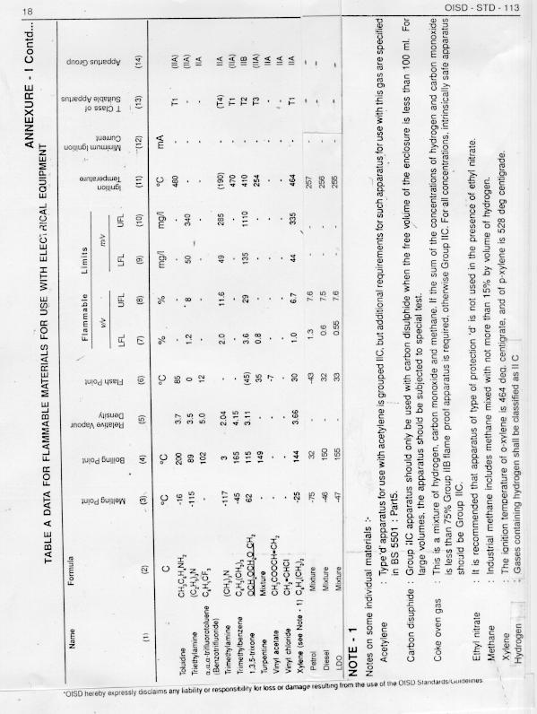
10 2 (ii) which, when mixed with air in certain proportions will form an hazardous atmosphere. Flammable Liquid A liquid capable of producing a flammable vapour, gas or mist under any foreseeable operating conditions. (iii) Flammable Mist Droplets of flammable liquid, dispersed in air, so as to form a hazardous atmosphere. 3.8 TEMPERATURE CLASS A system of classification by which an electrical apparatus is allocated temperature classes according to its maximum surface temperature. 3.9 IGNITION SOURCE Source of ignition is any electrical installation operating at energy levels sufficient to release incendiary energy. NOTE: In any installation irrespective of size there may be numerous sources of ignition apart from those associated with electrical sources. Precautions may be necessary to ensure safety but guidance in this aspect is outside the scope of this standard NORMAL OPERATIONS Normal operation of a plant or installation includes start-up and shut down operations also INCENDIARY ENERGY Hot particle energy sufficient to ignite a specific ignitible mixture PROTECTED FIRED VESSEL Any fired vessel that is provided with equipment (such as flame arrestors, forced draft burners with safety controls and spark arrestors) designed to eleminate the air intake & exhaust as sources of ignition PRESSURISED ROOM A room which has been made safe by pressurising or purging with a plenum of safe atmosphere by maintaining a minimum of 25 Pa overpressure than that of surrounding atmosphere with all door and windows closed. 4.0 CLASSIFICATION OF PRODUCTS 4.1 GENERAL Three basic conditions must be satisfied for the occurence of fire or explosion as indicated below. (i) (ii) A flammable gas or vapour must be present. It must be mixed with air or oxygen in the proportions required to produce a flammable or ignitible mixture. (iii) There must be an ignition source of this mixture. The potential source of ignition is electrical installation operating at energy level sufficient to release incendiary energy. While analysing any potential hazard, the quantity of the substance that might be liberated, its physical characteristics and the natural tendency of vapours to disperse in the atmosphere should be cosidered in detail. 4.2 FLAMMABLE SUBSTANCES & VAPOURS Flammable substances, the potential release of which must be considered in area classification for electrical insallations, include flammable gases, liquefied petroleum gases (LPG) and vapours of flammable liquids Flammable Gases Flammable gases commonly encountered include methane and its mixture with small quanities of low-molecular weight hydrocarbons. These gases are generally lighter than air. Hydrogen because of its unique properties, shall be given special consideration. Flammable gases released from an opening of given size will dissipate rapidly because of their low relative density and will not usually affect as wide an area as the liquefied petroleum gases Liquefied Petroleum Gas Liquefied Petroleum gases include propanes, propylenes, butanes, butylenes and their mixtures having relative densities from 1.5 to approximately 2.0 times more than that of air. Vapour pressure of these gases exceed 2.81 kg/cm2 at 37.8 degree C.
11 OISD - STD These gases in their liquefied state are highly volatile and have low boiling temperature so that they readily pick up heat creating large volumes of vapour. They should be treated very conservatively in considering the extent of areas affected, since the heavy vapours travel along the ground for long distances if air currents do not assist diffusion Flammable Liquids Flammable liquids vary in volatility and have a flash point below 93 degree C. These are divided into three classes as follows on the basis of volatility. CLASS A : Flammable liquids having flash point below 23 degree C. CLASS B : Flammable liquids having flash point 23 degree C and above but below 65 degree C. CLASS C : Flammable liquids having flash point 65 degree C & above but below 93 degree C. The saturated vapours of these flammable liquids at atmospheric pressure & ambient temperature are generally heavier than that of air and tend to settle at lower levels. Class A liquids may produce large volumes of vapour when released in appreciable quantities to the open. Class B liquids are heavier and less volatile than Class A but flash point is at or slightly below normal ambient air temperatures. At normal storage temperatures such liquids release vapour slowly and are hazardous only near the surface of the liquid. At elevated temperatures Class B liquids approach the characteristics of Class A liquids in respect of vapour release. Class C liquids include a broad range from cleaner s solvent to heavy fuel oil in commercial grades. The degree of hazard is low because the rate of vapour release is nil at normal ambient temperatures of handling and storage. When vapours from heated Class C products in process area released to the atmosphere, the chance of ignition by electrical equipment is not as great as in case of Class A or Class B liquids because vapours either condense rapidly or ignite spontaneously. Normally Class A and Class B liquids will produce vapours considered to be in flammable range for electrical design purposes. Class C liquids should be considered as producing flammable vapours when handled, processed or stored under such conditions that the temperature of the liquid, when released to the atmosphere, would exceed its flash point. 4.3 GAS GROUPS (APPARATUS GROUP) All gases normally encountered in industry are categorised into Group-I and Group-II gases. Group-I gases are those which are found in the coal mining industry and are not covered in this standard. Basis of classifying gases & vapours into various groups shall be as per IS Group-II gases have been further subdivided into three main representative subgroups namely Group-IIA, Group-IIB, and Group-IIC in the increasing order of their explosiveness. The representative gas for each of these subgroups being propane, ethylene and hydrogen respectively. It should be noted that apparatus subgrouping is normally applied specifically to the technique of flame proof enclosure and to the limiting energy levels of the intrinsic safety type of protection. Apparatus certified for a particular subgroup may be used with gases allocated to a lower subgroup subject to consideration of temperature classification. A table having the properties of a few flammable gases, vapours and liquids and apparatus subgroup is attached (Refer Table 'A' in Annexure - I). 5.0 CLASSIFICATION OF HAZARDOUS AREA 5.1 GENERAL Areas classified herein cover both temporarily and permanently installed facilities under normal operations in which abnormal conditions may exist for which practical protection is possible. The standard does not cover a major catastrophe against which practical protection is impossible. All hazardous areas containing ignitable and explosive mixtures are classified. The term abnormal is used in a limited 3
12 4 sense. Catastrophic in this context is applied, for example to the rupture of process vessel or a pipeline. Area classification norms do not apply to catastrophic failures that are beyond the concept of abnormality in this code. Normal operation is intended to be the situation that all plant equipment is operating within its design parameters and includes start up and shut down operation. Minor releases of flammable material may be part of normal operation but leakage which entail repair or shut down are not part of normal operation. The heavier than air vapours are not as easily dissipated in the atmosphere as the lighter than air vapour. Also lighter than air gas or vapour will rise in a comparatively still atmosphere whereas heavier than air gas or vapour will tend to sink and may thereby spread some distance horizontally at a low level. 5.2 AREA CLASSIFICATION To determine the type of electrical installation appropriate to a particular situation, the hazardous areas have been classified into three zones namely zone - 0, zone - 1 and zone - 2 according to the probability of the presence of hazardous atmosphere Zone - 0 An area in which a flammable atmosphere is present continuously or is likely to be present for long periods. Examples are vapour space above closed process vessels, storage tanks or closed containers, areas containing open tanks of volatile, flammable liquids etc Zone-1 Area in which an explosive gas/mixture is likely to occur in normal operation. Zone-1 locations may be distinguished when any of the following conditions exist : - Flammable gas or vapour concentration is likely to exist in the air under normal operating conditions. - Flammable atmospheric concentration is likely to occur frequently because of maintenance, repairs or leakage. - Failure of process, storage or other equipment is likely to cause an electrical system failure simultaneously with the release of flammable gas or liquid. - Flammable liquid or vapour piping system containing valves, meters, screwed or flanged fittings is in an inadequately ventilated area. - The area below the surrounding elevation or grade is such that flammable liquids or vapours may accumulate therein. The zone-1 classification typically includes: i) Imperfectly fitted peripheral seals of floating-roof tanks. ii) iii) iv) Inadequately ventilated pump rooms for volatile, flammable liquids. Interiors of Sample Retention Room/ Cabinet as part of quality control laboratories, refrigerators and freezers in which volatile flammable materials are stored in lightly stoppered or easily breakable containers. API Separators v) Oily waste water sewer/basins vi) Zone-2 LPG cylinder filling and cylinder evacuation area. vii) Areas in the immediate vicinity of vents and filling hatches. Areas in which an explosive gas/air mixture is not likely to occur in normal operation and if it occurs it will exist only for a short time. Zone-2 locations may be distinguished when any one of the following conditions exist: - The system handling flammable liquid or vapour is in an adequately ventilated area and is so designed and operated that the explosive or ignitable liquids, vapours or gases will normally be confined within closed containers or closed systems from which they can escape only during abnormal conditions such as accidental failure of a gasket or packing. - The flammable vapours can be conducted to the location as through trenches,
13 OISD - STD pipes or ducts. - Locations adjacent to Zone-1 areas. - In case positive mechanical ventilation is used, the failure or abnormal operation of ventilating equipment can permit atmospheric vapour mixtures to build up to flammable concentrations. 5.3 AREAS NOT CLASSIFIED In general, the following locations where flammable petroleum gases and volatile liquids are processed, stored, or handled are not classified. These areas are considered safe from the point of view of electrical installation. (a) Areas where the piping system is without valves, fittings, flanges or similar appurte-nances. (b) Areas where flammable liquids or vapours are transported only in suitable containers of vessels. (c) Areas where permanent ignition sources are present like areas where combustion occurs, for example flare tips, flare pits and other open flames. (d) Enclosed premises in which a plenum or purging stream of safe atmosphere is continuously maintained, so that no opening therein may be a point of ingress of gas or vapours coming from external source of hazard. (e) Gas turbine installation meeting requirements of Annexure-II (f) Diesel Generator room / shed having adequate ventillation. (g) Oil/gas fired boilers installation: Consideration should be given, however, to potential leak sources in pumps, valves etc. or in waste product and fuel lines feeding flame or heat producing equipment to avoid installing electrical devices which could then become primary ignition sources for such leaks. NOTE: (i) (ii) A protected fired vessel is not considered a source of ignition and the surrounding area is classified the same as for a hydrocarbon pressure vessel. The area around the fired components and exhaust outlets of unprotected fired vessels need not be classified from the standpoint of electrical equipment. (iii) The area around a flare tip or a flare pit need not be classified from the stand point of installation of electrical equipment. (iv) Electrical equipment may be exposed to flammable gas during a purge cycle of a fired heater or furnace thereby requiring protecting measures as applicable. 6.0 EXTENT OF HAZARDOUS AREA 6.1 GENERAL CONSIDERATIONS Properties of Flammable Materials A complete knowledge of the physical properties of the flammable materials involved is essential for classifying a hazardous area. Properties of primary interest from an ignition standpoint are: (a) Relative density (b) Flammable limits (c) Flash point (d) Volatility (e) Ignition temperature (f) Ignition energy Some of these characteristics have a direct influence on the degree and/or extent of hazardous areas while the others affect the design of electrical equipment (a) Where a gas or vapour is released into the atmosphere having a relative density less than one, the lighter vapour will rise in a comparatively still atmosphere. A vapour density greater than one, that is heavier than-air indicates the gas or vapour will tend to sink, and may thereby spread over some distance horizontally at a lower level. The latter effects will increase with compounds of greater relative vapour density. Note: In process industries, the boundary between compounds which may be considered lighter-than-air is set at a relative vapour density of This limit is chosen so as to provide a factor
14 6 of safety for those compounds whose densities are close to that of air, and where movement may not therefore be predicted without a detailed assessment. (b) The lower the lower flammable limit the larger may be the extent of the hazardous area. (c) A flammable atmosphere cannot exist if the flash point is significantly above the relevant maximum temperature of the flammable liquid. The lower the flash point, the larger may be the extent of the hazardous area. (d) Boiling point can be used for comparing the volatility of flammable liquids. The more volatile a liquid and the lower will be its flash point, the more closely it approxi-mates a flammable gas. (e) Ignition temperature and ignition energy of a flammable gas or vapour affect the design of electrical apparatus for hazardous areas so that these do not present an ignition risk Factors Affecting Extent of Hazard In adition to the properties of flammable materials involved, following factors need to be considered for determining the degree and extent of hazardous area while applying the guidelines given in this document. (a) The extent of a hazardous area may increase with increasing temperature of process liquid provided the temperature is above the flash point. It should be noted that the liquid or vapour temperature after the release may be increased or decreased by the ambient temperature or other factors e.g. a hot surface. NOTE: Some liquids such as certain halogenated hydrocarbons do not possess a flash point although they are capable of producing a flammable atmosphere; in these cases, the equilibrium liquid temperature corresponding to saturated concentration at lower flammable limit should be compared with the relevant maximum liquid temperature. (b) For flammable liquids, the concentration of the released vapour is related to the vapour pressure at the relevant maximum liquid temperature. The lower the initial boiling point the greater the vapour pressure for given liquid temperature and hence the greater concentration of vapour at the release source resulting in greater extent of hazardous area. (c) The extent of hazardous area may increase with increasing rate of release of flammable material. (d) Due to an improved dilution for release of flammable gases, vapours and/or mists in the air, the extent of hazardous area may decrease if, with constant release velocity increases above that which causes turbulent flow. (e) Air currents may substantially alter the outline of the limits of potential hazard. A very mild breeze may serve to extend the area in those directions to which vapours might normally be carried. However, a stronger breeze may so accelerate the dispersion of vapours that the extent of potentially hazardous area would be greatly reduced. (f) With an increased rate of ventilation, the extent of hazardous area may be reduced. The extent may also be reduced by an improved arrangement of the ventilation system. (g) Obstacles e.g. dykes, walls may impede the ventilation and thus may enlarge the extent. On the other hand, they may limit the movement of a cloud of an explosive gas atmosphere and thus may reduce the extent. (h) Elevated or depressed sources of release will alter the areas of potential hazards. (i) For vapour released at or near ground level, the areas where potentially hazardous concentrations are most likely to be found are below ground, those at ground are next most likely, and as the
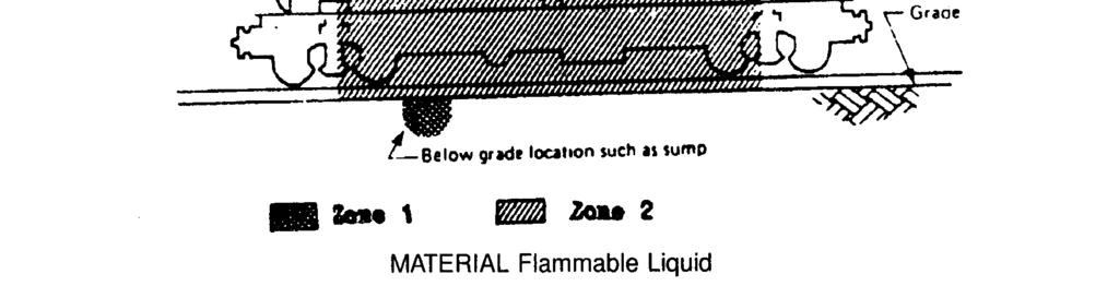
15 OISD - STD height above ground increases, the potential hazard decreases. Note: For lighter-than-air gases the opposite is true, there being little or no potential hazard at the below ground and greater potential hazard above ground While OISD standard 118 : Layout for Oil & Gas Installations indicates interdistances between various facilities, OISD-113 refers to distances pertaining to classification of areas for electrical installations. 6.2 HEAVIER THAN AIR GASES & VAPOURS Open Air Situations Figures 1 and 2 illustrate the situation when a source of hazard which may give rise to a hazardous atmosphere only under abnormal conditions is loctated in the open air. The hazardous area should in this case be classified as Zone 2. For heavier-than-air gases and vapours the classified hazardous area shall extend vertically 8 m above the source of hazard and horizontally 16 m in all directions from the source of hazard. Beyond 8 m from the source of the hazard in the horizontal plane the vertical extent of the Zone 2 area may be reduced to 8 m above ground level If there is a possibility of large release of volatile products, the Zone 2 area may be further extended horizontally beyond 16 m up to 32 m with a height of 0.63 m In case of petroleum pipelines where wellmaintained valves, fittings, and meters of a pipeline system transporting petroleum (crude oil, products, and gases) are installed in wellventilated situations or in a pit, the extent of the Zone 2 area above ground may be reduced to 4 m in all directions from the possible source of hazard, although the pit itself should be classified as Zone 1 area. Note: Any trench or pit below ground level and located within the area defined above should be classified as Zone 1 area. NOTES: 1. If the source of hazard gives rise to a hazardous atmosphere under normal operating conditions, the area described in as Zone 2 should be classified as Zone In the event of an enclosed premises not containing a source of hazard but situated within either a Zone 1 or Zone 2 area the inside of the premises should be classified as Zone 1 unless separated from the outside hazardous area by a fire wall Enclosed Premises and surrounding areas Zone 2 Classification - Figure 3 illustrates the situation when a source of hazard which may give rise to a hazardous atmosphere under abnormal conditions is located within enclosed premises. The whole of the inside of the building should be classified as Zone 1, as rapid dispersal of hazardous atmosphere may not be expected due to lack of ventilation The Zone 2 area shall extend 16 m horizontally from the source of hazard and 8 m vertically from the ground level. If the area covered above does not contain the area 3 m past the perimeter of the building, the Zone 2 area shall be extended in such a way that this area is covered. In case of unpierced vapourtight walls, the area 3 m past perimeter need not be considered within Zone 2 area If there is a possibility of large release of volatile products, Zone 2 area may be further extended horizonally beyond 16 m up to 32 m with height of 0.63 m. NOTE - Any trench or pit below ground level and located within the area defined should be classified as Zone 1 area Zone 1 Classification - If the source of hazard within the enclosed premises gives rise to hazardous atmosphere under normal conditions, the area within the building should be classified as Zone 1 and the area described in & as Zone 2 should be classified as Zone When the building has a ridge type roof with ventilators and not a sealed roof as shown in Fig. 3, special consideration is necessary in 7
16 8 connection with the vertical extent of the hazardous area. Fig.8 : Source of hazard located outside the enclosure with one side open Storage Tanks Figure 4 illustrates the classification of the area surrounding a floating-roof tank under normal operating conditions. The space above the roof and within the shell of the tank should be classified as Zone The area surrounding the tank should be classified as Zone 2. It shall extend vertically 3 m above the tank or shall be horizontally 3 m from it. If there is a dyke on one side of the tank, Zone 2 area should extend up to the dyke, the vertical extension from the ground level being the same as the height of the dyke In addition, the area extending 1.6 m beyond the shell top in all outward directions shall be considered as Zone 1 area In the case of fixed-roof tanks, the area surrounding the tank shown in Fig 4 as Zone 2 should be classified as Zone 1. However, in case of fixed roof tanks which breathe into closed system and not to atmosphere (during filling/emptying ), area surrounding the tank shall be classified as Zone - 2, as shown in Fig - 4. NOTE - Any trench or pit below ground level and located within the area defined should be classified as Zone 1 area. 6.3 LIGHTER THAN AIR, GASES AND VAPOURS Figures 5, 6, 7 and 8 detail the extent of hazardous area for a source of hazard located in open air for following situations: Fig.5 Fig.6 Fig.7 : Point of hazard in the air. : Source of hazard located inside enclosed premises with restricted ventilation(openings on top & bottom). : Source of hazard located inside enclosed premises with restricted ventilation(openings on sides). 6.4 For typical installation encountered in plants handling oil and gas, area classification for certain additional cases is given in the following figures. Fig.9 - Cooling tower handling process cooling water. Fig Tank car/tank truck loading unload-ing via open system. Fig 11 - Tank car/tank truck loading via closed system. Fig 12 - Drum dispensing installation. Fig 13 - Vent installation. Fig 14 - Ball or pig launching or receiving installation in a nonenclosed adequately ventillated area. Fig 15 - Enclosed premises with internal source of release. Fig 16 - Storage for cryogenic liquids. Fig 17 - Separators, Dissolved Air Floatation (DAF) Units, and Biological Oxidation (BIOX) Units. 7.0 REFERENCES i) IS 5571 Guide for Selection of Electrical Equipment for Hazardous Area ii) iii) iv) IS 5572 Classification of Hazardous Areas (other than mines) having Flammable Gases & vapours for Electrical Installations IS 9570 Classification of Flammable Gases or Vapours with Air according to their Maximum Experiment Safe Gaps and Minimum Igniting Current IS Code of Practice for the Selection, Installation and Maintenance of Electrical Apparatus for Use in Potentially Explosive Atmospheres v) IS General Requirements for Electrical
17 OISD - STD Apparatus for Explosive Gas Atmos-pheres ix) API RP 500 Classification of locations for Electrical Installations in Petroleum Refineries SP-30 (BIS) National Electric Code x) Oil Mines Regulations vi) The Petroleum Rules 1976 vii) NFPA 497A Recommended Practice for Classification of Class I Hazardous (Classified) Location for Electrical Installations in Chemical Process AreaS xi) NFPA 30 Flammable and Combustible Liquids Code xii) NFPA 45 Standard on Fire Protection for Laboratories Using Chemicals viii)
18 10
19 OISD - STD
20 12
21 OISD - STD
22 14
23 OISD - STD
24 16
25 OISD - STD
26 18
27 OISD - STD ANNEXURE - II GAS TURBINE INSTALLATIONS A-1 INTRODUCTION A-1.1 This Annex applies to gas fired turbine installations. A-1.2 If the turbine is equipped with an acoustic hood or other enclosure containing parts of the fuel gas system, this enclosure should be defined as the turbine hood. A-1.3 If the turbine, with or without a turbine hood, is located in an enclosed area, this area should be defined as the turbine room. A-2 AREA CLASSIFICATION OF THE TURBINE ROOM A-2.1 In order to classify the turbine room as non hazardous, the following requirements should both be fulfilled: a) The turbine room should be adequately ventilated that is at least 12 air changes per hour with proper ventilation patterns. The ventilation system should be arranged so that an over-pressure of at least 50 Pa (0.5 mbar) is maintained in the turbine room with respect to the inside of the turbine hood and any surrounding classified areas with openings to the turbine room. A pressure switch should be installed in order to give an alarm if the differential pressure drops below 50 Pa (0.5 mbar). b) The fuel gas pipe to each turbine hood should have no more than one pair of flanges inside the turbine room. All other requirement as valves, connections, filters, drip pot, etc, have to be located either : outside the turbine room inside an enclosure separately ventilated inside the turbine hood provided a special ventilation of turbine hood inside turbine hood, provided a special fuel gas supply arrangement as described in A-4 A-2.2 The turbine room may be classified as Zone 1 or Zone 2 if the arrangement is not in compliance with the requirements stated in A- 2.1 or due to other sources of hazard outside the turbine hood. The turbine or any associated equipment including exhaust piping, should not have a surface temperature above 200 C or above 80 percent of the ignition temperature for the actual gas/air mixture in the classified area without special precautions. A-3 VENTILATION OF THE TURBINE ROOM A-3.1 The turbine hood for a gas fired turbine should be adequately ventilated with respect
28 20 OISD - STD to the removal of heat from the machinery and dilution of flammable gas. The air should be taken from non-hazardous area. A-3.2 If the area outside the turbine hood is classified as non-hazardous, the ventilation system should be arranged so that an under-pressure of at least 50 Pa (0.5 mbar) is maintained inside the turbine hood with respect to the outside. This differential pressure may be the combined effect of the under-pressure inside the turbine hood and the over-pressure in the turbine room. A-3.3 If the area outside the turbine hood is Zone 2 and the turbine hood contains any source of ignition such as a surface with temperature above 200 C, or above 80 percent of the ignition temperature for the actual gas/air mixture the ventilation system of the turbine hood should be arranged so that an over-pressure of at least 50 Pa (0.5 mbar) is maintained inside the hood with respect to the outside. A-3.4 In both situations described above a pressure switch should be installed in order to give an alarm and shutdown after time delay if the differential pressure drops below 50 Pa (0.5 mbar). A-3.5 The number of leakage sources under the turbine hood should be kept to a minimum. However, a manufacturer may require some leak-prone equipment to be located inside the turbine hood. The number of air changes required depends upon the probable sources of leakage, the surface temperature of the machine, etc. Examples are given in A-4. A-3.6 As an alternative to ventilation of the turbine hood during shutdown of the turbine. Halon may be injected. A-3.7 Provided electrical equipment inside the hood which does not meet zone requirement, the turbine hood should be pre-purged with at least 5 air changes before starting the turbine or energizing any electrical equipment not suitable for Zone 1 area. A-3.8 The fan used for pre-purging should meet Zone 1 and should be equipped with a starter suitable for Zone 1 or a starter in an area remaining non-hazardous during shutdown. A-4.1 The combination of ventilation, fuel gas system arrangement, temperature on exposed surfaces, electrical equipment inside the turbine hood, etc, should be considered to evaluate the safety of the turbine hood. The safety principles will be elucidated by some of the most common turbine/turbine hood designs. A-4.2 No Exposed Surface of the Turbine Inside the Hood will have a Temperature Above 200 C During Operation. Provided the ventilation system provides at least 12 air changes per hour, the hood should be considered as adequately ventilated. The area inside the hood will be regarded as zone 2 area and accordingly all equipment inside the hood have to meet Zone 2 requirement. The equipment which has to be alive after a shut down or stop of ventilation of the hood, should meet Zone 1 requirement. This for instance applies to trace heater, post lubrication pumps etc. The post lubrication pumps should be supplied from emergency power sources to operate after a shutdown in order to prevent overheating of the bearings. Overheating may ignite flammable vapour or gas inside the hood. A-4.3 The Turbine has Exposed Surfaces with Temperature Above 200 C If the actual flammable gas ignition temperature can be tested and a statement can be made that the surface temperature of the turbine will not exceed 80 percent of the ignition tempe-rature, the same situation as described in A-4.2 above exists. A-4.4 The Turbine has exposed Surfaces with Temperature above 80 Percent of the Ignition Temperature of the Actual Flammable Gas or the Electrical Equipment inside the Hood which will be Alive as the Turbine is Running does not meet Zone 2 Requirement The hood then should be ventilated with sufficient number of air changes per hour to make a highly efficient dilution of any hazardous gas leakage inside the hood. The required ventilation rate depends on the leakage A-4 AREA CLASSIFICATION OF THE TURBINE HOOD
29 OISD - STD sources inside the hood and should be sufficient to keep the internal atmosphere below an average of 20 percent of the lower explosion limit. Ninety air changes per hour is regarded as a minimum. In addition to the normal ventilation system a 100 percent spare stand-by fan supplied from a continuous power source should be provided. If the ordinary ventilation fails the spare fan should be automatically activated and an alarm be given in the control room. As an alternative to ventilation of the turbine-hood during shutdown of the turbine, HALON may be injected. A-4.5 During a shut-down, the turbine hood may be classified as non-hazardous due to special arrangement of the fuel gas supply system. A system called Block and Bleed is described on Fig. 2. A shut down signal will close valve No. 1 and open valve No. 2. The three way valve will open from the gas distribution manifold to the flare. The fuel gas lines within the turbine room and the turbine hood will then be depressurized. The probability of gas escape inside the hood may then be regarded as minor. In case of a leak only small quantities of gas will escape. This arrangement does not reduce the requirements to ventilation while the turbine is running. A-5 DETECTION OF ESCAPED GAS A-5.1 Gas detectors should be installed inside the turbine hood. Normally, the turbine should shut down if gas is detected inside the hood. A-5.2 The location of the detectors should be chosen with special care being aware of possible gas pockets, air flow patterns, etc. A-5.3 Concerning ventilation arrangement, several alternatives exist in case of a shut down due to gas detection inside the hood. a) The ventilation of the turbine hood continues until hot surfaces have been cooled to a temperature below 80 percent of the ignition temperature of the gas-air mixture which is present. The ventilation system that will be in operation after a shut down should be supplied from an emergency power source with sufficient capacity. b) The ventilation stops and inert gas (for example Halon) is released upon detection of gas inside the hood. Other alternatives may be considered depending on the actual installation. A-6 ADDITIONAL RECOMMENDATIONS A-6.1 The shut down of ventilation system should correspond to the fire and gas detection system and the fire extinction system installed in the turbine hood and turbine room. Accordingly, other arrangements than those described in this standard may give an equivalent level of safety. A-6.2 Ventilation and combustion air should be taken from non-hazardous areas.
30 22 OISD - STD ANNEXURE - III
31 OISD - STD

32 24 OISD - STD Note 3
33 OISD - STD
34 26 OISD - STD - 113

35 OISD - STD


36 28 OISD - STD - 113

37 OISD - STD
38 30 OISD - STD - 113
39 OISD - STD
40 32 OISD - STD - 113
41 OISD - STD
42 34 OISD - STD Notes : 1. The extent of the classified areas shown shall be modified as required by the proximity ofother potential sources of release of nearby obstructions. Such as dikes or hills, that would impede dispersal of vapors. Distances given are for typical refinery installations : they must be used with judgement. With consideration given to all factors discussed in the text. 2. This dimension usually varies from 3 m to 8 m dependent on the volume of the volatiles. 3. Applies to open top tanks or basins. 3. Distance above top of basin tank. Extend to grade for basns or tanks located above ground. Figure 17 SEPARATORS, DISSOLVED AIR FLOATION (DAF) UNITS, AND BIOLOGICAL OXIDATION (BIOX) UNITS
43 <<Back Home Next >>
EXPLOSIVE ATMOSPHERES - CLASSIFICATION OF HAZARDOUS AREAS (ZONING) AND SELECTION OF EQUIPMENT
 AND SELECTION OF EQUIPMENT") EXPLOSIVE ATMOSPHERES - CLASSIFICATION OF HAZARDOUS AREAS (ZONING) AND SELECTION OF EQUIPMENT OVERVIEW ASSESSING THE RISK RELATIONSHIP BETWEEN FIRES AND EXPLOSIONS CLASSIFYING HAZARDOUS AREAS INTO ZONES
EXPLOSIVE ATMOSPHERES - CLASSIFICATION OF HAZARDOUS AREAS (ZONING) AND SELECTION OF EQUIPMENT OVERVIEW ASSESSING THE RISK RELATIONSHIP BETWEEN FIRES AND EXPLOSIONS CLASSIFYING HAZARDOUS AREAS INTO ZONES
TABLE OF CONTENT
 Page : 1 of 12 Project Engineering Standard www.klmtechgroup.com KLM Technology #03-12 Block Aronia, Jalan Sri Perkasa 2 Taman Tampoi Utama 81200 Johor Bahru Malaysia TABLE OF CONTENT SCOPE 2 REFERENCES
ANNEX AMENDMENTS TO THE INTERNATIONAL CODE FOR FIRE SAFETY SYSTEMS (FSS CODE) CHAPTER 15 INERT GAS SYSTEMS
 CHAPTER 15 INERT GAS SYSTEMS") Annex 3, page 2 ANNEX AMENDMENTS TO THE INTERNATIONAL CODE FOR FIRE SAFETY SYSTEMS (FSS CODE) CHAPTER 15 INERT GAS SYSTEMS The text of existing chapter 15 is replaced by the following: "1 Application This
Annex 3, page 2 ANNEX AMENDMENTS TO THE INTERNATIONAL CODE FOR FIRE SAFETY SYSTEMS (FSS CODE) CHAPTER 15 INERT GAS SYSTEMS The text of existing chapter 15 is replaced by the following: "1 Application This
SECTION 2 APPLICATION OF FUNDAMENTALS
 SECTION 2 APPLICATION FUNDAMENTALS ENVIRONMENTAL CONDITIONS IN NEC CLASS I HAZARDOUS LOCATIONS Section II covers a great number of illustrations which can be applied directly to a hazardous area under
PSSI 36 General Confined Spaces, Tunnels, Culverts and Similar Spaces
 1. SCOPE This document now includes provision for safe access to cable tunnels and culverts previously covered in PSSI 37 which is now withdrawn. The term Confined Space is defined in the Confined Spaces
API RECOMMENDED PRACTICE 500 THIRD EDITION, DECEMBER 2012 ERRATA, JANUARY 2014
 Recommended Practice for Classification of Locations for Electrical Installations at Petroleum Facilities Classified as Class I, Division 1 and Division 2 API RECOMMENDED PRACTICE 500 THIRD EDITION, DECEMBER
ESCONDIDO FIRE DEPT TRAINING MANUAL Section Truck Module Page 1 of 5 Utilities Gas Emergencies Revised
 Truck Module Page 1 of 5 GAS EMERGENCIES Introduction Natural gas and Liquid Propane Gas (LPG) are flammable gases. Many households and commercial buildings utilize these gases for everything from heating
PART II RULES FOR THE CONSTRUCTION AND CLASSIFICATION OF VESSELS IDENTIFIED BY THEIR MISSIONS TITLE 104 CARRIAGE OF DANGEROUS GOODS
 PART II RULES FOR THE CONSTRUCTION AND CLASSIFICATION OF VESSELS IDENTIFIED BY THEIR MISSIONS TITLE 104 CARRIAGE OF DANGEROUS GOODS SECTION 7 ELECTRICITY CHAPTERS A APPROACH B DOCUMENTS, REGULATIONS AND
DSEAR-Classification of Hazardous Areas (Zoning) and Selection of Equipment
 and Selection of Equipment") OHSS: Classification of Hazardous areas (Zoning) and selection of equipment Guidance 202 DSEAR-Classification of Hazardous Areas (Zoning) and Selection of Equipment Contents Overview... 2 Assessing the
OHSS: Classification of Hazardous areas (Zoning) and selection of equipment Guidance 202 DSEAR-Classification of Hazardous Areas (Zoning) and Selection of Equipment Contents Overview... 2 Assessing the
Fires and Explosions: What You Need to Know to Prevent Them
 Fires and Explosions: What You Need to Know to Prevent Them CSChE PSM Symposium Edmonton, Alberta 2007 Gerry Phillips, GC Phillips Consulting Ltd. Norman Nibber, Independent Risk Control Objectives Understand
Focus on VOC Emissions Reduction Using an Oxygen Based Inerting Control System For Inert Gas Blanketing of Chemical Process Vessels
 Inerting Control Systems by NTRON PROCESS ANALYZER DIVISION of NEUTRONICS INC. EXTON. PA. 19341 RJN Rev. A June 2001 Focus on VOC Emissions Reduction Using an Oxygen Based Inerting Control System For Inert
Inerting System Design for Medium Speed Vertical Spindle Coal Pulverizers TABLE OF CONTENTS
 Inerting System Design for Medium Speed Vertical Spindle Coal Pulverizers The PRB Coal Users Group plans to develop a Design Guide for Mill Inerting as an aid to users when designing a mill inerting system.
API MPMS Chapter 17.6 Guidelines for Determining the Fullness of Pipelines between Vessels and Shore Tanks
 API MPMS Chapter 17.6 Guidelines for Determining the Fullness of Pipelines between Vessels and Shore Tanks 1. Scope This document describes procedures for determining or confirming the fill condition of
Session #: Selection of Explosion Protected Equipment for Hazardous Locations
 Abstract Session #: (Arial 16) Selection of Explosion Protected Equipment for Hazardous Locations Pieter Coetzee Explosion Prevention Consultant Registered person How can we mitigate the risks of explosions
ENGINEERING STANDARD FOR HAZARDOUS AREA ORIGINAL EDITION DEC. 1994
 ENGINEERING STANDARD FOR HAZARDOUS AREA ORIGINAL EDITION DEC. 1994 This Standard is the property of Iranian Ministry of Petroleum. All rights are reserved to the owner. Neither whole nor any part of this
Class 2 Gases Learning Tool
 Class 2 Gases Learning Tool This work has been produced by DGL (Aust) Pty Ltd This Learner s Guide is about the skills and knowledge required to store and warehouse Class 2 Gases at DGL (Aust) facilities.
TABLE OF CONTENTS PART 2 - CONFINED SPACES
 May 11, 2006 TABLE OF CONTENTS PART 2 - CONFINED SPACES Page DEFINITIONS... 2-1 GENERAL... 2-2 RESPONSIBILITIES... 2-2 HAZARD ASSESSMENT AND WORK PROCEDURES... 2-3 IDENTIFICATION AND ENTRY PERMITS... 2-3
ISO INTERNATIONAL STANDARD. Small craft Liquefied petroleum gas (LPG) systems
 systems") INTERNATIONAL STANDARD ISO 10239 Second edition 2008-02-15 Small craft Liquefied petroleum gas (LPG) systems Petits navires Installations alimentées en gaz de pétrole liquéfiés (GPL) Reference number ISO
INTERNATIONAL STANDARD ISO 10239 Second edition 2008-02-15 Small craft Liquefied petroleum gas (LPG) systems Petits navires Installations alimentées en gaz de pétrole liquéfiés (GPL) Reference number ISO
AIDGC PRESENTATION MARCH 2006 HAZARDOUS AREAS STANDARDS & CLASSIFICATION
 AIDGC PRESENTATION MARCH 2006 HAZARDOUS AREAS STANDARDS & CLASSIFICATION Jeff Strath Principal Engineer Paterson Flood Engineers Pty Ltd www.pfe.com.au INTRODUCTION This presentation provides an overview
2.9 GENERAL REQUIREMENTS FOR GROUP I
 2.9 GENERAL REQUIREMENTS FOR GROUP I Group I represents closed sources of hazard that contain Class I flammable products with lighter-than-air gases or vapors located outdoors that are sufficiently ventilated
Chapter 7. Coal Cargoes. Properties and Characteristics 7.1
 Chapter 7 Coal Cargoes This chapter, and all of the chapters in Part 2, should be read in conjunction with the booklet Carrying Solid Bulk Cargoes Safely (Reference 16), published by Lloyd s Register/UK
U. S. OIL & REFINING CO. M A T E R I A L S A F E T Y D A T A S H E E T
 U. S. OIL & REFINING CO. M A T E R I A L S A F E T Y D A T A S H E E T Page 1 of 5 MIXED BUTANE MSDS No. 611100 Revised 8/10/98 U. S. OIL & REFINING CO. EMERGENCY ASSISTANCE: 3001 Marshall Ave. COMPANY:
RESOLUTION A.567(14) adopted on 20 November 1985 REGULATION FOR INERT GAS SYSTEMS ON CHEMICAL TANKERS
 adopted on 20 November 1985 REGULATION FOR INERT GAS SYSTEMS ON CHEMICAL TANKERS") INTERNATIONAL MARITIME ORGANIZATION A 14/Res.567 16 January 1986 Original: ENGLISH ASSEMBLY - 14th session Agenda item lo(b) IMO RESOLUTION A.567(14) adopted on 20 November 1985 THE ASSEMBLY, RECALLING
INTERNATIONAL MARITIME ORGANIZATION A 14/Res.567 16 January 1986 Original: ENGLISH ASSEMBLY - 14th session Agenda item lo(b) IMO RESOLUTION A.567(14) adopted on 20 November 1985 THE ASSEMBLY, RECALLING
Section 1.3: PRESSURE VESSEL COMPONENTS AND SYSTEMS AND COMPRESSED GAS CYLINDERS
 Section 1.3: PRESSURE VESSEL COMPONENTS AND SYSTEMS AND COMPRESSED GAS CYLINDERS TABLE OF CONTENTS Page A. Regulations, Standards and References 1.3-2 B. Scope 1.3-2 C. Design Features for the Storage
METHOD 21 - DETERMINATION OF VOLATILE ORGANIC COMPOUND LEAKS. 1.2 Scope. This method is applicable for the
 1151 METHOD 21 - DETERMINATION OF VOLATILE ORGANIC COMPOUND LEAKS 1.0 Scope and Application. 1.1 Analytes. Analyte Volatile Organic Compounds (VOC) CAS No. No CAS number assigned 1.2 Scope. This method
PSM TRAINING COURSES. Courses can be conducted in multi-languages
 Courses can be conducted in multi-languages One set of hardcopy course notes will be sent to client for printing and distribution to course participants. The courses will be held at the client s training
RESOLUTION MSC.397(95) (adopted on 11 June 2015) AMENDMENTS TO PART A OF THE SEAFARERS' TRAINING, CERTIFICATION AND WATCHKEEPING (STCW) CODE
 (adopted on 11 June 2015) AMENDMENTS TO PART A OF THE SEAFARERS' TRAINING, CERTIFICATION AND WATCHKEEPING (STCW) CODE") RESOLUTION MSC.397(95) (adopted on 11 June 2015) THE MARITIME SAFETY COMMITTEE, RECALLING Article 28(b) of the Convention on the International Maritime Organization concerning the functions of the Committee,
RESOLUTION MSC.397(95) (adopted on 11 June 2015) THE MARITIME SAFETY COMMITTEE, RECALLING Article 28(b) of the Convention on the International Maritime Organization concerning the functions of the Committee,
Safety in Petroleum Industry
 Chemical ( Industrial ) Disaster Management Conference, Bangalore 30 January 2014 Safety in Petroleum Industry Refineries and Petrochemical plants are highly energyintensive Handle highly inflammable and
Cryogenic Storage of Ammonia
 Cryogenic Storage of Sachin D Chavan Abstract Gases such as ammonia, chlorine, LPG, propane, propylene, ethane, ethylene etc need to be stored at low temperatures. Cryogenic storage of such fluids is a
DSEAR- Storage, Use and handling of gas cylinders guidance.
 OHSS: Storage, Use and handling of gas cylinders guidance 202 DSEAR- Storage, Use and handling of gas cylinders guidance. Contents Introduction... 2 General recommendations for storage, use and handling....
Rules for Classification and Construction Ship Technology
 I Rules for Classification and Construction Ship Technology 1 Seagoing Ships 9 Oil Recovery Vessels Edition 1993 The following Rules come into force on 1st September, 1993. The respective latest edition
Dow s New Practice for Locating Temporary Portable Buildings. P. Partridge 9/29/05 UNRESTRICTED - May be shared with anyone Slide 1
 Dow s New Practice for Locating Temporary Portable Buildings P. Partridge 9/29/05 UNRESTRICTED - May be shared with anyone Slide 1 Dow guidelines issued following the explosion at BP s Texas City facility
LIQUEFIED PETROLEUM GAS (LPG) AND NATURAL GAS (NG) - FIRE PREVENTION ISSUES
 AND NATURAL GAS (NG) - FIRE PREVENTION ISSUES") p. 53-62, DOI 10.2478/v10281-012-0012-y LIQUEFIED PETROLEUM GAS (LPG) AND NATURAL GAS (NG) - FIRE PREVENTION ISSUES Seamus MURPHY 1 Review article Abstract: Key words: In this paper it is proposed to identify
p. 53-62, DOI 10.2478/v10281-012-0012-y LIQUEFIED PETROLEUM GAS (LPG) AND NATURAL GAS (NG) - FIRE PREVENTION ISSUES Seamus MURPHY 1 Review article Abstract: Key words: In this paper it is proposed to identify
Dangerous Substances & Explosive Atmospheres Regulation 2002 The Basics. Richard Cowen Dip SH, Dip RSA, CMIOSH, MIIRSM, FRSPH, GI Fire E
 Dangerous Substances & Explosive Atmospheres Regulation 2002 The Basics Richard Cowen Dip SH, Dip RSA, CMIOSH, MIIRSM, FRSPH, GI Fire E DSEAR Regulations 2002 Sets minimum requirements for the protection
Installation of Ballast Water Management Systems
 (Sept 2015) (Rev.1 May 2016) Installation of Ballast Water Management Systems 1. Application In addition to the requirements contained in BWM Convention (2004), the following requirements are applied to
 Title of Paper Interpretation of IP15 in Process Plant Design: a Commonsense Approach ---------------------------------------------------------------------------------------------------------------------------
Guidance on room integrity testing and its interpretation
 Guidance Note Guidance on room integrity testing and its interpretation Guidance on room integrity testing and its interpretation 1. SCOPE... 6 2. INTRODUCTION AND BACKGROUND... 6 2.1. DEVELOPMENT OF INTEGRITY
FLAMMABLE GASES AND FLAMMABLE CRYOGENIC FLUIDS
 CHAPTER 35 FLAMMABLE GASES AND FLAMMABLE CRYOGENIC FLUIDS SECTION 3501 GENERAL 3501.1 Scope. The storage and use of flammable gases shall be in accordance with this chapter. Compressed gases shall also
Process Safety Management Of Highly Hazardous Chemicals OSHA 29 CFR
 Process Safety Management Of Highly Hazardous Chemicals OSHA 29 CFR 1910.119 PSM - Definition Not all refining hazards are caused by the same factors or involve ve the same degree of potential damage.
INTERNATIONAL ASSOCIATION OF CLASSIFICATION SOCIETIES. Interpretations of the. IGF Code
 INTERNATIONAL ASSOCIATION OF CLASSIFICATION SOCIETIES s of the IGF Code CONTENTS GF1 Test for gas fuel tank s high level alarm Rev.1 July 2017 GF2 Ship Steel Protection against Liquefied Gas Fuel (Part
BASF Flash Fire FRC Assessment Tool
 BASF Flash Fire FRC Assessment Tool Introduction The assessment tool offered in this document was developed to assist BASF manufacturing units in evaluating the potential for flash fire occurrence and
UNIVERSITY OF BATH HEALTH & SAFETY STANDARD Confined Spaces
 UNIVERSITY OF BATH HEALTH & SAFETY STANDARD Confined Spaces Version Number Version 1 Date of Approval 20 th December 2016 Review Date Three years from acceptance by the UHSC Author & Lead Aims Scope Relevant
Drum / cylinder handling
 Page 1 of 8 Drum / cylinder handling This Technical Measures Document covers the storage and handling of toxic and flammable substances in drums and cylinders and refers to relevant codes of practice and
SAFETY MANUAL FOR FLAMMABLE PRODUCT TRANSFER
 SAFETY MANUAL FOR FLAMMABLE PRODUCT TRANSFER SUPPLIMENT TO eom IMPORTANT READ THIS MANUAL BEFORE PRODUCT INSTALLATION, OPERATION, INSPECTION & MAINTENANCE Tougher and more rigid guidelines are being established
Module 6. Tightness Testing
 Module 6 Tightness Testing IGE / UP / 1B New Tightness Testing Procedure Covers pipework up to 35mm and installation volumes of 0.035m3 Objectives By the end of Module 6, Tightness Testing and Direct Purging
TABLE OF CONTENT
 Page : 1 of 11 Project Engineering Standard www.klmtechgroup.com KLM Technology #03-12 Block Aronia, Jalan Sri Perkasa 2 Taman Tampoi Utama 81200 Johor Bahru Malaysia TABLE OF CONTENT SCOPE 2 REFERENCES
Inerted Vessels: Preventing Hazards Caused by Gas Buoyancy
 Inerted Vessels: Preventing Hazards Caused by Gas Buoyancy 2008 Mary Kay O Connor O Process Safety Center International Symposium College Station, Texas Tuesday, October 28, 2008 presented by Russell A.
SAFETY MANUAL PURGING, VENTING & DRAINING PROCEDURE TABLE OF CONTENTS 1. INTRODUCTION SCOPE DEFINITIONS PROCEDURE...
 Page 1 of 11 TABLE OF CONTENTS 1. INTRODUCTION... 2 2. SCOPE... 2 3. DEFINITIONS... 2 4.... 3 5. RESPONSIBILTIES... 10 6. REFERENCES... 10 7. ATTACHMENTS... 11 8. APPENDICES... 11 Rev. Issue Date Amendment
GUIDANCE FOR MANAGING THE RISKS ASSOCIATED WITH END OF LIFE LPG VEHICLES
 GUIDANCE FOR MANAGING THE RISKS ASSOCIATED WITH END OF LIFE LPG VEHICLES NSW QUAD BIKE SAFETY IMPROVEMENT PROGRAM SNAPSHOT 2016 17 Disclaimer This publication may contain information about the regulation
TECHNICAL DATA MAINTENANCE AIR COMPRESSOR MODEL G-1
 Dry 131h 1. DESCRIPTION The Viking Model G-1 Maintenance Air Compressor is an electric motor-driven, aircooled, single-stage, oil-less compressor. The unit is equipped with a check valve and provides a
NZQA registered unit standard version 3 Page 1 of 6
 Page 1 of 6 Title Report on the integrity of explosion-protected electrical apparatus in explosive atmospheres Level 3 Credits 3 Purpose This unit standard covers the explosion-protection aspects of plant
This document is meant purely as a documentation tool and the institutions do not assume any liability for its contents
 1999L0092 EN 27.06.2007 001.001 1 This document is meant purely as a documentation tool and the institutions do not assume any liability for its contents B DIRECTIVE 1999/92/EC OF THE EUROPEAN PARLIAMENT
Describe Flammable Gas Measurement
 Training Module Describe Flammable 100% 90% C 80% No Combustion 70% 60% 50% 40% 30% 20% UEL B Combustion No Combustion 10% 0% LEL A Human Development HDC Human Development All rights reserved. No part
GUIDELINES ON SAFETY MANAGEMENT SYSTEMS FOR HOT WORK AND ENTRY INTO ENCLOSED SPACES
 OIL COMPANIES INTERNATIONAL MARINE FORUM GUIDELINES ON SAFETY MANAGEMENT SYSTEMS FOR HOT WORK AND ENTRY INTO ENCLOSED SPACES The OCIMF mission is to be the foremost authority on the safe and environmentally
LIVE STEAMERS GAS FIRING CODE OF PRACTICE GAS FIRING OF AMBSC BOILERS AUSTRALIAN ASSOCIATION OF
 GAS FIRING Document control This document consists of the following sections with the version dates shown. Sections 1 to 9 dated: 07 April 2012 This document consists of 12 pages (including cover). Authoring,
Remark: When calling at especially tank cleaning installations located outside the yard area, a certificate of call is not required.
 1 Annex 1 Safety regulations for certain activities on vessels with tanks for oil, etc. (TANK REGULATIONS) Drawn up in accordance with section 29 of act no. 226 of 11 June 1954 on general protection of
KENYA STANDARD KS 2386: PART 8: 2018 Emergency procedure guide- Transport (Road, Rail) Part 8: Gases
 Part 8: Gases") KENYA STANDARD KS 2386: PART 8: 2018 Emergency procedure guide- Transport (Road, Rail) Part 8: Gases No copying of this standard without KEBS permission except as permitted by copyright law TECHNICAL COMMITTEE
KENYA STANDARD KS 2386: PART 8: 2018 Emergency procedure guide- Transport (Road, Rail) Part 8: Gases No copying of this standard without KEBS permission except as permitted by copyright law TECHNICAL COMMITTEE
ZUERCHER TANK REGULATORS PRINCIPLES OF TANK VENTILATION
 Why Inertisation (blanketing) of Tanks? General Tank inertisation or blanketing is required in many applications where products or liquids stored in the tank are processed and/or filled into and emptied
MAGB HEALTH and SAFETY GROUP Working In Confined Spaces
 MAGB HEALTH and SAFETY GROUP Working In Confined Spaces SCOPE: This document represents best practice advice available and considered pertinent after consultation within the membership and incorporating
Cal/OSHA T8 CCR 1536 Cal/OSHA T8 CCR 4799 Cal/OSHA T8 CCR 4845 Cal/OSHA T8 CCR 4848
 Cal/OSHA Gas Systems for Welding GAS WELDING Cal/OSHA T8 CCR 1536 Cal/OSHA T8 CCR 4799 Cal/OSHA T8 CCR 4845 Cal/OSHA T8 CCR 4848 When performing gas welding, the following precautions, work procedures,
Safe management of industrial steam and hot water boilers A guide for owners, managers and supervisors of boilers, boiler houses and boiler plant
 Health and Safety Executive Safe management of industrial steam and hot water boilers A guide for owners, managers and supervisors of boilers, boiler houses and boiler plant Background Accidents involving
PUBLIC COMPANY ORLEN LIETUVA OCCUPATIONAL HEALTH AND SAFETY PROCEDURE BDS-12 USE OF PORTABLE GAS ANALYZERS I. GENERAL
 PUBLIC COMPANY ORLEN LIETUVA APPROVED BY Deputy Director of Quality, Labor Safety and Environmental Control Director 30 November 2017 Order No TV1(1.2-1)-457 OCCUPATIONAL HEALTH AND SAFETY PROCEDURE BDS-12
Air Eliminators and Combination Air Eliminators Strainers
 Description Air Eliminators and Combination Air Eliminator Strainers are designed to provide separation, elimination and prevention of air in piping systems for a variety of installations and conditions.
Welding, Cutting, and Brazing
 Welding, Cutting, and Brazing Hazards of Welding Operations Fire hazards Metal splatter Electric shock Explosion hazards Released gases Radiant energy Where would these hazards be found on oil and gas
CHAPTER 6 VENTILATION REQUIREMENTS
 CHAPTER 6 VENTILATION REQUIREMENTS A. General When there is no air movement, a flammable gas or vapor released to the atmosphere will spread in all directions. With air movement, the flammable gas or vapor
COMPRESSED GASES CHAPTER 53
 CHAPTER 53 COMPRESSED GASES SECTION 5301 GENERAL 5301.1 Scope. Storage, use and handling of compressed gases in compressed gas containers, cylinders, tanks and systems shall comply with this chapter, including
1.8 INDUSTRIAL PROCESS WEIGHING IN HAZARDOUS AREAS
 1.8 INDUSTRIAL PROCESS WEIGHING IN HAZARDOUS AREAS EXPLOSION PROTECTION In addition to the type approval and certification of industrial weighing systems concerned with accuracy, equipment that is also
FIRE AND EXPLOSION HAZARD MANAGEMENT
 FIRE AND EXPLOSION HAZARD MANAGEMENT Toolbox Talk Practical Applications (Part 2) Setting the standard in oil and gas safety 1 WHAT SHOULD I KNOW ABOUT FIRES AND EXPLOSIONS» One-size-fits-all solution
CITY AND COUNTY OF DENVER CR&CF RISK UNIT Compressed Gas Safety Standard
 CITY AND COUNTY OF DENVER CR&CF RISK UNIT 65.5.11 Compressed Gas Safety Standard 1.0 Introduction 2.0 Scope This standard has been developed to protect all City and County of Denver employees and contractors
RESOLUTION MSC.365(93) (adopted on 22 May 2014) AMENDMENTS TO THE INTERNATIONAL CONVENTION FOR THE SAFETY OF LIFE AT SEA, 1974, AS AMENDED
 (adopted on 22 May 2014) AMENDMENTS TO THE INTERNATIONAL CONVENTION FOR THE SAFETY OF LIFE AT SEA, 1974, AS AMENDED") RESOLUTION MSC.365(93) THE MARITIME SAFETY COMMITTEE, RECALLING Article 28(b) of the Convention on the International Maritime Organization concerning the functions of the Committee, RECALLING ALSO article
RESOLUTION MSC.365(93) THE MARITIME SAFETY COMMITTEE, RECALLING Article 28(b) of the Convention on the International Maritime Organization concerning the functions of the Committee, RECALLING ALSO article
Pressure Equipment Directive (PED) 97/23/EC Page 033 of 124
 97/23/EC Page 033 of 124") Pressure Equipment Directive (PED) 97/23/EC Page 033 of 124 13.7 Pressure Equipment Directive (PED) 97/23/EC 1 The Pressure Equipment Directive (PED) 97/23/EC applies to the design, manufacturing and conformity
Pressure Equipment Directive (PED) 97/23/EC Page 033 of 124 13.7 Pressure Equipment Directive (PED) 97/23/EC 1 The Pressure Equipment Directive (PED) 97/23/EC applies to the design, manufacturing and conformity
RULES PUBLICATION NO. 119/P
 RULES PUBLICATION NO. 119/P PERIODIC SURVEYS OF FUEL INSTALLATIONS ON SHIPS OTHER THAN LIQUEFIED GAS CARRIERS UTILIZING GAS OR OTHER LOW FLASH POINT FUELS 2019 January Publications P (Additional Rule Requirements)
The evolution of the Ex-proof flame path
 April 2017 The evolution of the Ex-proof flame path As written in previous dissertation, the most critical part of a flameproof enclosure 'Ex d' is the flame path. Although the Standards are divided into
Periodic Survey of Fuel Installations on Ships other than Liquefied Gas Carriers utilizing gas or other low flash point fuels
 (Jan 2017) Periodic Survey of Fuel Installations on Ships other than Liquefied Gas Carriers utilizing gas or other low flash point fuels CONTENTS 1. Application 2. Special Survey 2.1 Schedule 2.2 Scope
Hot Work Practice. Operations Health & Safety. Safe Work Management. Occupational Safety. Manager, Central Health & Safety. H&S Programs & Projects
 Operations Health & Safety Hot Work Practice Program H&S Discipline Content Owner Custodian Document Number Safe Work Management Occupational Safety Manager, Central Health & Safety H&S Programs & Projects
Flammability Chart. Gas Formula Ignition
 Leak Detection 101 Investigating a leak is simplified if you know the basics. By J. Scott Kleppe Sensit (J and N Enterprises, Inc.) Every day new gas services are added to provide economical energy to
Lessons Learnt Case Report
 Lessons Learnt Case Report Flash Fire in Confined Space August 2009 RBA-LLCR-006 Contents Page 1. Introduction 1 2. Summary of Events 1 3. Findings 2 4. Analysis 6 5. Conclusion 7 6. Recommendations 8
MATERIAL SAFETY DATA SHEET SPRAY 'N' LIFT/LABEL REMOVER AUGUST Distributor's name and address
 MATERIAL SAFETY DATA SHEET AUGUST 2000 SECTION I GENERAL INFORMATION Distributor's name and address PerfectData Corporation 110 West Easy Street Simi Valley, California 93065-1689 (805) 581-4000 PRODUCT
(b) Venting or flaring shall only be authorized by the Commission under the following circumstances:
 Venting or flaring shall only be authorized by the Commission under the following circumstances:") Chapter 3, Section 39. Authorization for Flaring and Venting of Gas. (a) Venting or flaring must be in accordance with Commission requirements to prevent waste as specified in W.S. 30-5-101(a)(i)(G), 102(a),
Chapter 3, Section 39. Authorization for Flaring and Venting of Gas. (a) Venting or flaring must be in accordance with Commission requirements to prevent waste as specified in W.S. 30-5-101(a)(i)(G), 102(a),
NZQA registered unit standard version 3 Page 1 of 7. Plan electrical installations for explosive atmospheres
 Page 1 of 7 Title Plan electrical installations for explosive atmospheres Level 5 Credits 8 Purpose This unit standard is intended for use in the training and assessment of people who work with electrical
Intrinsic safety 101 hazardous locations
 Intrinsic safety 101 hazardous locations Protection methods, containment, segregation, and prevention By Robert Schosker This article answers the question, Why worry about hazardous locations? The area
Working in Gas Hazard Areas
 / Health & Safety OPERATIONS STANDARDS Ref.: Aperam Safety ST 012 Working in Gas Hazard Areas Issue: 15.05.2012 Vers.: v0 Rev.: AM Safety ST 012 v1.2 08.05.2012 Working in Gas Hazard Areas Controlled Updated
Label 2.2: Non-flammable, Non-toxic gas 1. IDENTIFICATION OF THE SUBSTANCE/PREPARATION AND OF THE COMPANY/UNDERTAKING
 Page 1 of 5 Label 2.2: Non-flammable, Non-toxic gas 1. IDENTIFICATION OF THE SUBSTANCE/PREPARATION AND OF THE COMPANY/UNDERTAKING Trade name : NITROGEN, REFRIGERATED LIQUID (N2) MSDS Nr : LNS101 Use :
Having reviewed the Law on Constructional Organisation of Buildings promulgated by Legislative Decree No.(13) of 1977, as amended,
 of 1977, as amended,") MINISTRY OF LABOUR MINISTERIAL ORDER NO.(15) OF 2014 WITH RESPECT TO PROTECTING WORKERS FOR THE HAZARDS OF HIGHLY FLAMMABLE LIQUIDS AND LIQUEFIED PETROLEUM GASES AT ESTABLISHMENTS AND WORKSITES The Minister
MINISTRY OF LABOUR MINISTERIAL ORDER NO.(15) OF 2014 WITH RESPECT TO PROTECTING WORKERS FOR THE HAZARDS OF HIGHLY FLAMMABLE LIQUIDS AND LIQUEFIED PETROLEUM GASES AT ESTABLISHMENTS AND WORKSITES The Minister
National Fire Protection Association. 1 Batterymarch Park, Quincy, MA Phone: Fax:
 National Fire Protection Association 1 Batterymarch Park, Quincy, MA 02169-7471 Phone: 617-770-3000 Fax: 617-770-0700 www.nfpa.org M E M O R A N D U M TO: FROM: NFPA Technical Committee on Electrical Equipment
PRAGMATIC ASSESSMENT OF EXPLOSION RISKS TO THE CONTROL ROOM BUILDING OF A VINYL CHLORIDE PLANT
 PRAGMATIC ASSESSMENT OF EXPLOSION RISKS TO THE CONTROL ROOM BUILDING OF A VINYL CHLORIDE PLANT L.P. Sluijs 1, B.J. Haitsma 1 and P. Beaufort 2 1 Vectra Group Ltd. 2 Shin-Etsu (contact details: Vectra Group
PROPERTY & ESTATES GROUP
 PROPERTY & ESTATES GROUP SAFE WORKING PROCEDURE 2-17-04 WORKING IN CONFINED SPACES Purpose of Document This document describes SRUC s policy and procedure for working in confined spaces. It applies to
Applications Note: Use of "pentane equivalent" calibration gas mixtures
 Introduction The gas that is used to verify accuracy is every bit as important as the detector itself when it comes to worker safety. Choosing (and using) the right mixture is critical to the success of
Atmospheric Hazards. Hazardous Atmosphere 3/29/2017. Oxygen deficiency and enrichment Flammable gases and vapors Toxic contaminants
 2017 Wisconsin Safety Council Safety & Health Conference, Presentation by Tim Gackle, OSHA Training Institute April 11, 2017 Atmospheric Hazards Oxygen deficiency and enrichment Flammable gases and vapors
SAFETY IN CONFINED SPACES AND HEALTH SAFETY EXPLOSION HAZARD - TOXIC HAZARD
 a five page issue revision of 1-1995 When paints containing solvents are applied in enclosed or confined spaces, two hazards can exist, explosion and toxicity and precautions must be taken to eliminate
TYPICAL TOXIC GAS SYSTEM INSPECTION VIOLATIONS
 TYPICAL TOXIC GAS SYSTEM INSPECTION VIOLATIONS The following is a list of typical violations often found by inspectors and a generic solution. You can use this list to improve the safety of your facility,
General Inspection Guidance for Waste Management Units Requiring Air Emission Controls Under RCRA Air Standard Subpart CC
 United States Environmental Protection Agency RCRA Programs Branch Region IV Atlanta, GA CAA/RCRA Air Rules 27 November 2000 General Inspection Guidance for Waste Management Units Requiring Air Emission
When you complete this module you will be able to: Describe procedures needed to enter into, or work safely in confined spaces.
 Confined Space Entry Learning Outcome When you complete this module you will be able to: Describe procedures needed to enter into, or work safely in confined spaces. Learning Objectives Here is what you
Refrigerant R170 - ETHANE
 Material Safety Data Sheet Refrigerant R170 - ETHANE Revision 09/04 1 CHEMICAL PRODUCT AND COMPANY IDENTIFICATION Advanced Gas Technologies 1401 Stauffer Road Palm, PA 18070 Telephone Number: (215) 541-4116
Hot Work Program. University of Wisconsin-Platteville Reviewed 4/2016
 Hot Work Program University of Wisconsin-Platteville Reviewed 4/2016 The purpose of the Hot Work Program is to establish safety procedures for employees, contractors, and subcontractors engaging in any
COAL MINES TECHNICAL SERVICES, GAS DETECTION RELATED SERVICES FOR MINES RESCUE
 COAL MINES TECHNICAL SERVICES, GAS DETECTION RELATED SERVICES FOR MINES RESCUE Peter Mason Manager, Coal Mines Technical Services, a division of Mines Rescue Pty Ltd, Australia ABSTRACT The NSW Mines Rescue
PRACTICAL EXPERIENCES IN THE PRODUCTION OF INSULATION FOAMS WITH HYDROCARBON BLOWING AGENT IN DEVELOPING AND DEVELOPED COUNTRIES
 PRACTICAL EXPERIENCES IN THE PRODUCTION OF INSULATION FOAMS WITH HYDROCARBON BLOWING AGENT IN DEVELOPING AND DEVELOPED COUNTRIES R I S T O O J A L A, U N I D O F O A M S E C T O R C O N S U LTA N T SAFETY
Vision Painting Inc Safety Management System
 Abrasive Blasting 1. PURPOSE The purpose of this program is to provide training and qualification guidelines for the safe operation of Abrasive Blasting. The Safety Officer is responsible for facilitating
Bauman Machine Inc. COMPRESSED GAS CYLINDER SAFETY
 Bauman Machine Inc. COMPRESSED GAS CYLINDER SAFETY Many industrial and laboratory operations require the use of compressed gases for a variety of different operations. Compressed gases present a unique
Working Environment Safety Assessment
 For your own safety and/or safety of your workforce, and to improve the efficiency of your business practices, you should be aware of, and be up to date with, the key safety issues and good practices relevant