Eksigent MicroLC 200 Plus System. Operator Guide
|
|
|
- Constance Elliott
- 5 years ago
- Views:
Transcription
1 RUO-IDV B September 2014
2 This document is provided to customers who have purchased AB Sciex equipment to use in the operation of such AB Sciex equipment. This document is copyright protected and any reproduction of this document or any part of this document is strictly prohibited, except as AB Sciex may authorize in writing. Software that may be described in this document is furnished under a license agreement. It is against the law to copy, modify, or distribute the software on any medium, except as specifically allowed in the license agreement. Furthermore, the license agreement may prohibit the software from being disassembled, reverse engineered, or decompiled for any purpose. Warranties are as stated therein. Portions of this document may make reference to other manufacturers and/or their products, which may contain parts whose names are registered as trademarks and/or function as trademarks of their respective owners. Any such use is intended only to designate those manufacturers' products as supplied by AB Sciex for incorporation into its equipment and does not imply any right and/or license to use or permit others to use such manufacturers' and/or their product names as trademarks. AB Sciex warranties are limited to those express warranties provided at the time of sale or license of its products and are AB Sciex s sole and exclusive representations, warranties, and obligations. AB Sciex makes no other warranty of any kind whatsoever, expressed or implied, including without limitation, warranties of merchantability or fitness for a particular purpose, whether arising from a statute or otherwise in law or from a course of dealing or usage of trade, all of which are expressly disclaimed, and assumes no responsibility or contingent liability, including indirect or consequential damages, for any use by the purchaser or for any adverse circumstances arising therefrom. For research use only. Not for use in diagnostic procedures. The trademarks mentioned herein are the property of AB Sciex Pte. Ltd. or their respective owners. Eksigent is a division of AB Sciex, LLC. AB SCIEX is being used under license AB Sciex Pte. Ltd. AB Sciex Pte. Ltd. Blk 33, #04-06 Marsiling Ind Estate Road 3 Woodlands Central Indus. Estate SINGAPORE of 140 RUO-IDV B D G
3 Contents Chapter 1 Foreword About this Guide Symbols and Conventions Safety Instructions Qualified Personnel Equipment Use and Modification Regulatory Compliance Symbols and Labels System Disposal (Waste Electrical and Electronic Equipment) Related Documentation Technical Support Chapter 2 Introduction System Description Accessory Options Chapter 3 Using the System The Example Experiment Guidelines for Sample Preparation Perform a Run Using the Analyst Software Verify the Analyst Software Hardware Profile Load the Mobile Phases Flush the Injection Valve Enable the Column Oven Equilibrate the Create the LC Methods Create the Acquisition Methods and the Batch Submit the Batch Monitor the Run Perform a Run Using the Eksigent Control Software Turn on the System Prepare the Create the LC Methods Create the Run Table Start the Run Monitor the Run Chapter 4 Routine Maintenance Basic Maintenance Schedule Dispose of Waste Inspect the System Maintenance Procedures for the Pump Purge Mobile Phases Replace the Pump Seal Rinse Re-initialize the Pressure Transducers Calibrate Flowmeters RUO-IDV B D G 3 of 140
4 Contents Check Flow Stability Maintenance Procedures for the Injection Valve Replace the Injection Port Fitting Replace the Sample Loop Replace the Injection Valve Rotor Seal Replace the Injection Valve Pod Plumb the Injection Valve Install the Electrode and Grounding Assembly for the Ion Source ESI Electrode Assemblies Maintenance Procedures for the Turbo V Ion Source Electrode Backflush the Electrode Sonicate the Electrode Maintenance Procedures for the Autosampler Replace the Wash Solvents Set the Temperature for the Stack Holder Replace the Autosampler Fuse Test the DLW System Verify the DLW Actuator Replace the Syringe Barrel Replace the Syringe Plunger Replace the Syringe Needle Configure the Autosampler Configure the Tray Holder Position Configure the Wash Station Position Configure the Injector Waste Position Configure the Injection Port Position Configure the Needle Penetration Depth Configure the Autosampler Tray Type Adjust the Needle Penetration into the Sample Vial Modify the Calibration Method for an AB SCIEX TripleTOF System Create the LC Method for the Calibration Method Template Update the Calibration Method Template Transfer System Settings to a Different Computer Troubleshooting a Move to a New Computer Store the System Chapter 5 Troubleshooting Troubleshooting Overview Testing Fluid Connections Troubleshooting Tables Appendix A Principles of Operation Microfluidic Flow Control How the MFC System Works Calculating the Flow Rate Pressure Required to Generate a Gradient Dynamic Flow Control Guidelines for Micro UHPLC Methods Flow Rate and Injection Volume Electrodes and Tubing of 140 RUO-IDV B D G
5 Contents Dynamic Load and Wash The DLW Process Communicating with the DLW Autosampler Method Parameters for the Autosampler Method Autosampler Method, Step-by-Step Parameters and Values in the Autosampler Method Appendix B System Specifications Appendix C Spare Parts and Accessories View and Order Spare Parts System Accessory Kit Consumables Kit Upgrade Kit Replacement Parts Revision History Index RUO-IDV B D G 5 of 140
6 Contents 6 of 140 RUO-IDV B D G
7 l Foreword 1 About this Guide This guide is intended for laboratory technicians who are responsible for control and day-to-day maintenance of the Eksigent MicroLC 200 Plus system. It is assumed that the user of this guide is familiar with standard laboratory terminology. Note: Read the safety instructions and the rest of this guide before using the Eksigent MicroLC 200 Plus system. Symbols and Conventions The following conventions are used throughout the guide. Table 1-1 Pictorial Caution: Symbols and Descriptions Description The danger sign warns about a hazard. It calls attention to a procedure or practice which, if not adhered to, could results in injury or loss of life. Do not proceed beyond a danger sign until the indicated conditions are fully understood and met. The warning sign denotes a hazard. It calls attention to a procedure or practice which, if not adhered to, could result in severe injury or damage or destruction of parts or all of the equipment. Do not proceed beyond a warning sign until the indicated conditions are fully understood and met. The caution signal word denotes a hazard. It calls attention to a procedure or practice which, if not adhered to, could result in damage or destruction of parts or all of the equipment. Do not proceed beyond a caution sign until the indicated conditions are fully understood and met. The tip sign signals relevant information. Read this information, as it might be helpful. The note sign signals additional information. It provides advice or a suggestion that may support you in using the equipment. This symbol indicates that the waste of electrical and electronic equipment must not be disposed as unsorted municipal waste and must be collected separately. Please contact an AB SCIEX field service employee for information concerning the decommissioning of equipment. RUO-IDV B D G 7 of 140
8 Foreword Safety Instructions The following safety instructions apply to the Eksigent MicroLC 200 Plus system: WARNING! Personal Injury Hazard: Use of this equipment in a manner not approved by the manufacturer may inhibit its safety protection. Caution: Potential System Damage! Changes or modifications to this unit not expressly approved by the manufacturer could void the instrument warranty and render the system inoperable. WARNING! Electrical Shock Hazard: Only use fuses of the type and current rating specified. Do not use repaired fuses or by-pass the fuse holder. WARNING! Electrical Shock Hazard: The supplied power cord must be used with a power outlet containing a protective ground contact. WARNING! Biohazard: When replacing tubing or fittings on the Eksigent MicroLC 200 Plus system, exposure to solvents may occur. It is therefore recommended that appropriate safety procedures be followed and personal protective equipment be used, according to the applicable Safety Data Sheets supplied by the solvent vendor. WARNING! Electrical Shock Hazard: Do not change the external or internal grounding connections. Tampering with or disabling these connections could create a safety hazard and/or damage the system. The instrument, as shipped, is properly grounded in accordance with normal safety regulations. WARNING! Electrical Shock Hazard: Do not turn the system on if you suspect that it has incurred any kind of electrical damage. Instead, disconnect the power cord and evaluate the system. WARNING! Electrical Shock Hazard: Electrical damage may have occurred if any part of the system shows visible signs of damage, exposure to liquids or of having been transported under severe stress. WARNING! Electrical Shock Hazard: Continue to exercise caution as capacitors inside the system may still be charged even after the system has been turned off. WARNING! Electrical Shock Hazard: Disconnect power cords from the power supply before attempting any type of maintenance. 8 of 140 RUO-IDV B D G
9 Foreword WARNING! Electrical Shock Hazard: The combination of the pump and autosampler with a LC/MS system may require additional safety measures as described by AB SCIEX. Refer to the mass spectrometer Safety Guide or System User Guide for instructions for the safe grounding on the LC/MS system. WARNING! Electrical Shock Hazard: Use a grounding cable connected between the injection valve's sample loop and an appropriate grounding point at the LC/MS source. This supplementary grounding will reinforce the safety configuration specified by AB SCIEX. Caution: Potential System Damage: Damage can result if the system is stored for prolonged periods under extreme conditions (for example, subjected to heat, water, etc.) WARNING! Environmental Hazard: Do not allow flammable and/or toxic solvents to accumulate. Follow a regulated, approved waste disposal program. Never dispose of flammable and/or toxic solvents into a municipal sewage system. Caution: Potential System Damage: To avoid damaging electrical parts, do not disconnect an electrical assembly while power is applied to the system. Once the power is turned off, wait approximately 30 seconds before disconnecting an assembly. Caution: Potential System Damage: The system contains a number of sensitive electronic components that may be damaged if exposed to excessive line voltage fluctuations and/or power surges. WARNING! Puncture Hazard: To avoid injury during operation, keep hands and loose objects away from the autosampler arm and syringe assembly. WARNING! Personal Injury Hazard: Use caution when working with any polymeric tubing under pressure: Always wear proper eye protection when near pressurized polymer tubing. Do not use polymer tubing that has been severely stressed or kinked. Do not use polymer tubing, in particular PEEK or DuPont Tefzel tubing, with tetrahydrofuran (THF), dimethylsulfoxide (DMSO), chlorinated organic solvents, concentrated mineral acids, such as nitric, phosphoric or sulfuric acids, or any related compounds. WARNING! Puncture Hazard: Do not operate the autosampler without the safety shield properly installed. Caution: Potential System Damage: An on-board lithium battery maintains the autosampler firmware when the instrument is turned off. It should only be replaced by a factory-authorized service engineer. RUO-IDV B D G 9 of 140
10 Foreword Caution: Potential Data Corruption: When you use the HTC-xt PAL autosampler for chromatographic analyses and observe a change in the retention of a particular compound, the resolution between two compounds or peak shapes, immediately determine the reason for the changes. Do not rely on the analytical results until the cause of the change is determined. Qualified Personnel After installing the system, the Field Service Employee (FSE) uses the Customer Familiarization Checklist to familiarize the customer on system operation, cleaning, and basic maintenance. Only AB SCIEX qualified personnel shall install, operate, and maintain the equipment. Equipment service shall only be conducted by AB SCIEX FSEs. Contact an AB SCIEX FSE for more information. Equipment Use and Modification Use the system indoors in a laboratory that complies with the environmental conditions recommended in the Site Planning Guide. If the system is used in an environment or in a manner not prescribed by AB SCIEX, the protection provided by the equipment can be impaired. Unauthorized modification or operation of the system may cause personal injury and equipment damage, and may void the warranty. Contact an AB SCIEX representative for more information on servicing the instrument. Regulatory Compliance This system complies with the standards and regulations listed in this section. Applicable labels have been affixed to the system. For more information, see the Declaration of Conformance included with the system. Canada Europe Safety CAN/CSA C22.2 No Electromagnetic Compatibility EN Class A and EN Safety EN WEEE 2002/96/EEC USA Safety UL International Electromagnetic Compatibility CISPR 11 Class A, IEC Safety IEC of 140 RUO-IDV B D G
.")

11 Foreword Symbols and Labels Table 1-2 Labels on the External Labels Definition WARNING: Use only the original power supply. Caution: Risk of needle-stick puncture. Caution or Refer to the. WARNING: Flush Gas. Refer to the Operator Guide for instructions on using a purge gas with the stack cooler. Do not dispose of equipment as unsorted municipal waste (WEEE). Direct Current A V V-A Amperes (current) Volts (voltage) Volts - Amperes (power) System Disposal (Waste Electrical and Electronic Equipment) Do not dispose of system components or subassemblies, including computer parts, as unsorted municipal waste. Follow local municipal waste ordinances for proper disposal provisions to reduce the environmental impact of WEEE (waste, electrical, and electronic equipment). To make sure that you safely dispose of this equipment, contact an FSE for instructions. European Union customers: Contact a local AB SCIEX Customer Service office for complimentary equipment pick-up and recycling. RUO-IDV B D G 11 of 140
12 Foreword Related Documentation PAL Installation and Operation User Manual contains detailed information about the autosampler. Printed and electronic copies are included. Eksigent Control Software User Guide installed with the Eksigent control software Analyst Software Getting Started Guide or System User Guide installed with the Analyst software Technical Support AB SCIEX and its representatives maintain a staff of fully-trained service and technical specialists located throughout the world. They can answer questions about the instrument or any technical issues that may arise. For more information, visit the web site at 12 of 140 RUO-IDV B D G

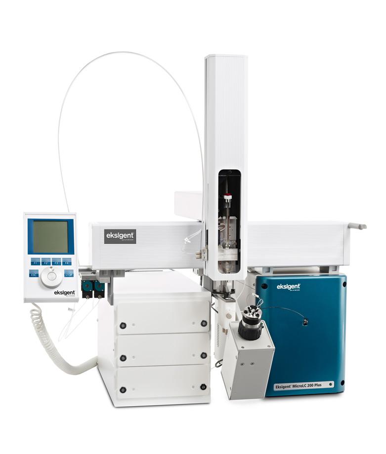
13 Introduction 2 The benefits of micro high-pressure liquid chromatography (HPLC) high sensitivity, fast separations and reduced solvent consumption can be achieved with careful attention to certain key operating procedures. There are subtle but important differences between liquid chromatography separations performed using 300 µm or 500 µm ID columns and those using 2.1 mm ID columns. This manual describes the basic operation and critical parameters to consider for routine and robust operation of the Eksigent MicroLC 200 Plus system. System Description Figure 2-1 The system includes: Binary gradient pumping system, with two flow rate configurations: 5 µl/min to 50 µl/min 20 µl/min to 200 µl/min Eksigent control software Eksigent system accessory kit, with three sample loops (2 µl, 5 µl, and 10 µl) a column, fittings, and other supplies (refer to System Accessory Kit on page 129) CTC Analytics HTC-xt PAL autosampler, including: 3-drawer cooling stack holder (additional options available) RUO-IDV B D G 13 of 140
14 Introduction Dynamic load and wash feature (DLW) (refer to Dynamic Load and Wash on page 111) PAL Loader software Object Manager software User documentation Column oven Accessory Options Depending upon the system you purchase, your system will have either: Column oven mounting kit (PN ) or AB SCIEX mass spectrometer interface kit (PN ), including: 65 µm stainless steel electrode (PN ) Column oven mounting kit (PN ) Clamp and rod assembly (PN ) Grounding kit (PN ) MS interface cable (PN ) 14 of 140 RUO-IDV B D G
15 Using the System 3 This chapter offers a brief tutorial on the use of the Eksigent MicroLC 200 Plus system, using either the Analyst software or the Eksigent control software. The procedures described in this chapter assume the system has already been properly installed and initialized. The Example Experiment The experiment consists of two samples, each injected three times on the 5 cm HALO fused-core C18 column installed with the system. The sample runs are followed by one injection of a blank sample (50:50 water:acetonitrile) to flush the electrode. The instructions below assume a 2 µl sample loop is installed on the system and the column is heated to 35 C. The mobile phases are water and acetonitrile. The aqueous channel for the pump (Channel A) will be filled with Mobile Phase A. The organic channel (Channel B) will be filled with Mobile Phase B, shown in Table 3-1. Table 3-1 Mobile Phases for the Example Experiment Mobile Phase Mixture Channel Mobile Phase A 100% water:0.1% formic acid Channel A Mobile Phase B 100% acetonitrile:0.1% formic acid Channel B Each run is one minute and has a gradient from 90% to 10% water, except for the final run to flush the electrode, which is 20 minutes and is isocratic 50% water and 50% acetonitrile. Guidelines for Sample Preparation For the best results with the Eksigent MicroLC 200 Plus system, follow the guidelines below for sample preparation. The flow path can clog if samples contain too much particulate matter. Use HPLC- or MS-grade solvents at all times. Avoid the use of non-volatile salts and buffers such as CHAPS, phosphate, TRIS, HEPES and perchlorates. These additives will foul the electrospray source and mass spectrometer orifice. Avoid overloading the column with sample. For 0.3 mm and 0.5 mm ID columns use <12 µg of material For 1 mm ID columns use <50 µg of material AB SCIEX recommends pre-filtering samples with 0.45 µm pore filters to avoid particulate contaminants which may cause clogging. If needed, centrifuge all samples at RPM for 5 minutes to remove dust and particulates from the sample solution. If sample filtration is not sufficient, the following techniques can be used: Protein precipitation (for biological samples) RUO-IDV B D G 15 of 140
16 Using the System Liquid-liquid extraction Solid-phase extraction Addition of an in-line filter or guard column to the flow path (refer to Table C-4 on page 132 for part numbers) Perform a Run Using the Analyst Software The following instructions walk through the example experiment using the Analyst software. Use these instructions when using the mass spectrometer and the Eksigent MicroLC 200 Plus system as an integrated system. These instructions assume you are familiar with the Analyst software. For more information, refer to the Analyst Software Getting Started Guide or the System User Guide, available from the Start menu. Complete the following steps in the order they appear: 1. Verify the Analyst Software Hardware Profile. 2. Load the Mobile Phases. 3. Flush the Injection Valve. 4. Enable the Column Oven. 5. Equilibrate the. 6. Create the LC Methods. 7. Create the Acquisition Methods and the Batch. 8. Submit the Batch. 9. Monitor the Run. Verify the Analyst Software Hardware Profile The active hardware profile must include the autosampler and the Eksigent control software to perform a run using the Analyst software. The FSE should configure your system for you, but if you are using a different computer or have uninstalled the Analyst software, the hardware profile may not be correct. 1. Start the Analyst software. 2. On the Navigation bar, under Configure, double-click Hardware Configuration. 16 of 140 RUO-IDV B D G

17 Using the System 3. In the Hardware Configuration Editor dialog, click each hardware profile to open it and locate a profile that contains a mass spectrometer, the autosampler, and the Eksigent control software as shown in Figure 3-1. Figure 3-1 Hardware Profile Configured for the Eksigent MicroLC 200 Plus System If an appropriate profile does not exist, create a profile as described in Create a Hardware Profile on page If the profile does not have a green check to the left, click Activate Profile. RUO-IDV B D G 17 of 140
 do the following: a.")
18 i Using the System The active profile appears with a check, the Eksigent control software launches and the Eksigent control software Acquisition window appears (Figure 3-2). Figure 3-2 Acquisition Window, Showing the LC Methods Button If the Acquisition window does not appear (indicating that the Eksigent control software did not start) do the following: a. Close the Analyst software. b. Select Start > Programs > Eksigent > Driver Configuration. c. Uninstall, and then reinstall the Analyst software drivers. d. Restart the Analyst software. Note: Do not start the Eksigent control software manually. Instead, allow the Analyst software to start the Eksigent control software. (When the Eksigent control software is launched independently, the LC Methods button appears as Run Manager.) 18 of 140 RUO-IDV B D G
.")
.")
19 Using the System Create a Hardware Profile 1. Click New Profile to open the Create New Hardware Profile dialog (Figure 3-3). Figure 3-3 Create New Hardware Profile Dialog 2. Type a name for the profile in the Profile Name field. 3. Add the autosampler. a. Click Add Device to open the Available Devices dialog (Figure 3-4). Figure 3-4 Available Devices Dialog, Showing Autosamplers RUO-IDV B D G 19 of 140

20 Using the System b. Select Autosampler in the Device Type list, click AutoSampler CTC PAL and then click OK. c. Click Setup Device to open the CTC PAL dialog (Figure 3-5). d. Type a volume in the Valve Loop Volume field. e. Click Configure and select the appropriate COM port. f. Click OK. Figure 3-5 Note: A 2 µl loop should be installed on the system. Enter a value between 5 µl and 100 µl in this field. The value is logged in the data file but does not affect the run. Future releases of the Analyst software will support smaller loop volumes (for example, 2 µl). CTC PAL Dialog 4. Click Add Device to add the Eksigent control software. a. Select Software Application in the Device Type list, then click Software Application <not configured>. b. Click OK. c. Click Setup Device to open the Software Application Settings dialog (Figure 3-6). d. Click Eksigent 1 and then click OK. 20 of 140 RUO-IDV B D G

21 Using the System Figure 3-6 Software Application Settings Dialog 5. Click Add Device to add the mass spectrometer. a. Select Mass Spectrometer in the Device Type list. b. Click the appropriate mass spectrometer in the list and then click OK. Tip! The correct instrument is usually highlighted in the list. 6. Click OK to save the profile and close the Create New Hardware Profile dialog Load the Mobile Phases For additional information about mobile phases for the Eksigent MicroLC 200 Plus system, refer to Recommendations for Mobile Phases on page Pour new mobile phase into the bottles, then insert the mobile phase transfer tubing and filters. 2. Specify the mobile phase information in the Eksigent control software. a. Click System > Mobile Phases to open the Mobile Phases dialog (Figure 3-7). b. For Binary Mixture A (mobile phase A), do not make any changes. c. For Binary Mixture B (mobile phase B), select Acetonitrile in the lower list and type 100 in the % field. d. (Optional) Type any comments in the Comments/Modifiers fields. RUO-IDV B D G 21 of 140
.")

22 Using the System Figure 3-7 Mobile Phases Dialog Settings for the Example Experiment 3. Purge the pumps a minimum of 20 times. a. Click More to display additional options in the dialog. b. In the Purge Settings section, select the pumps to be purged and set purge cycles to 20 (Figure 3-8). Figure 3-8 Note: If a mobile phase that is not listed in the Mobile Phases dialog is required for your experiment, either select a mobile phase from the list with a very similar viscosity or add a new one. Refer to Use a Custom Mobile Phase for instructions. Purge Settings Section of the Mobile Phases Dialog c. Click Purge Now. The pumps begin to execute purge cycles. While the pumps are purging, make sure the mobile phases are pulled through the mobile phase tubing to the pumps. d. Locate the waste tubing of the pumps being purged (the waste tubes are clear plastic tubing and emerge from the rear of the pump). After about 8 purges, the mobile phase should be purged through the waste tubing. 4. Flush the system. a. In the Flush Settings section, type 500 µl for the Total Volume (Figure 3-9). b. Set the Flush Flowrate based the configuration: Type 50 µl/min for the low-flow configuration. Type 100 µl/min for the high-flow configuration. 22 of 140 RUO-IDV B D G
23 Using the System Figure 3-9 Flush Settings Section of the Mobile Phases Dialog Settings for High-flow Configuration c. Connect one end of a length of 1/32 inch OD tubing to the mobile phase outlet on the front of the pump and insert the other end in a waste vial. Caution: Potential System Damage: Make sure that no LC columns are connected before proceeding with this operation. Flushing the system with a column connected could over-pressure the system and create leaks. d. Click Flush Now. e. When the flush sequence ends, click OK to close the dialog. Recommendations for Mobile Phases Mobile phases should be compatible with the following materials: 316L stainless steel, PTFE, FEP, PEEK, sapphire, glass, and fused silica. Some compatible solvents include water, acetonitrile, methanol, ethanol, n-propanol, isopropanol, hexane, heptane. Use a Custom Mobile Phase Some experiments require a mobile phase other than those available in the Eksigent control software. Add a custom mobile phase in the Mobile Phases dialog. Also, if you are using a mixture of two solvents in one bottle, create a custom mobile phase for the mixture. Required Materials Calibration kit (with 100 µl and 200 µl pipettes) (PN ) 1. Click System > Mobile Phases to open the Mobile Phases dialog. 2. Click More to show more options in the dialog (Figure 3-10). RUO-IDV B D G 23 of 140

24 Using the System Figure 3-10 Mobile Phases Dialog Expanded 3. In the Mobile Phase Change section, click Create New Fluid to open the Flowmeter Calibration dialog. 4. Follow the steps in the Flowmeter Calibration dialog. Adding a custom mobile phase includes performing a flowmeter calibration. For the calibration, select the calibration pipette based on the system configuration: Low-flow configuration 100 µl High-flow configuration 200 µl Flush the Injection Valve Flush the valve when the column is not connected to prevent introducing any contaminants from the valve to the column. 1. Make sure that the column is not connected. 2. Click System > Direct Control in the Eksigent control software to open the Direct Control dialog (Figure 3-11). Tip! You can also open the Direct Control dialog by clicking (Direct Control) in the Acquisition window. 3. In the Pump Direct Control section, select the Conserved Flow option and set both A (%) and B (%) to Set the Total flowrate to 20 µl/min. 24 of 140 RUO-IDV B D G

25 Using the System Figure 3-11 Direct Control Dialog 5. Click Start. 6. In the Valve Direct Control section, alternate clicking Load Position and Inject Position, waiting ~ 10 seconds between each click. 7. Perform step 6 twice more. 8. Click Load Position, then click Stop. Enable the Column Oven The temperature of the column compartment can be regulated, with a maximum temperature of 80 C. 1. Connect the column. Tip! When reconnecting the column, follow the tips in Best Practices for Working with PEEKsil Tubing on page 62 to prevent crushing the PEEKsil tubing and potentially clogging the system. 2. Click System > Direct Control in the Eksigent control software to open the Direct Control dialog. 3. In the Column Oven/Heater section, type 35 in the Setpoint field (Figure 3-12). RUO-IDV B D G 25 of 140
26 Using the System Figure 3-12 Direct Control Dialog Column Oven/Heater Section 4. Click Start. The oven will come to temperature quickly, however the column can take up to 30 minutes to stabilize to the oven temperature. Note: Do not operate the oven for an extended period of time without closing the compartment. Equilibrate the 1. Make sure that the LC column is connected. 2. Click System > Direct Control in the Eksigent control software to open the Direct Control dialog (Figure 3-13). 3. In the Pump Direct Control section, select the Conserved Flow option and set A (%) to 90 and B (%) to 10. This is the mobile phase composition used for equilibration. 4. Set the Total flowrate based on the configuration: 26 of 140 RUO-IDV B D G
27 Using the System Type 50 µl/min for the low-flow configuration Type 150 µl/min for the high-flow configuration. Figure 3-13 Direct Control Dialog Settings for High-flow Configuration 5. Click Start to begin equilibration. 6. Allow the system to equilibrate for approximately 10 minutes, then click Stop. 7. Click Close. Note: To avoid conflicts with the Analyst software after the system has equilibrated, be sure to click Stop to end pumping and then close the Direct Control dialog. Create the LC Methods An LC method contains the conditions used for separating the sample, including flow rate, flow mode, and mobile phase gradient. The Eksigent MicroLC 200 Plus system has two flow modes: Conserved you set the concentration and total flow rate and the system calculates the flow rate for each mobile phase. Independent you set the flow rate for each mobile phase and the system calculates the total flow rate. For the example experiment, two LC methods are required, a gradient for separating the sample and an isocratic method for flushing the system at the end of the batch or sequence. RUO-IDV B D G 27 of 140

28 Using the System Create the Separation Method This section creates a gradient LC method called Analysis Test. 1. Click LC Methods to display the LC Method Settings dialog. 2. In the Name box, type Analysis Test as the name for the method, and then click Save. 3. In the Column Information section, specify the values as shown in Figure Figure 3-14 LC Methods Settings Dialog Summary Tab 28 of 140 RUO-IDV B D G

29 Using the System 4. Click Run Conditions tab and specify the values shown in Figure Figure 3-15 LC Method Settings Dialog Run Conditions Tab The duration of the flow in the Flush the column for field should allow to 3 to 5 column volumes to pass through the system between runs. Depending on your experiment, a greater volume may be required. When the Stabilize column temperature check box is selected, the run does not begin until the column reaches the specified temperature ±0.1 C. There are four modes of sample injection. They differ in whether the sample loop stays in-line during the acquisition and how much of the contents of the sample loop is transferred to the column. None the sample valve does not actuate during the acquisition. Standard the sample valve moves to the inject position when acquisition begins and returns to the load position when acquisition ends. The sample loop remains in the flow path during acquisition. Metered the valve switches to the inject position when acquisition starts and the specified volume of sample is delivered to the column by the LC pumps at the specified flow rate. After the specified volume is injected, the sample valve switches to the load position, removing the sample loop from the flow path. RUO-IDV B D G 29 of 140

30 Using the System The minimum injection volume (in nanoliters) is given by 2.5 x Q, where Q is the flow rate. Use metered injection when the sample loop volume is larger than the volume to be injected on the column. With metered injection, the large sample loop doesn t add any extra dead-volume, preventing extra-column broadening. Rapid the valve operates as during metered injection, except the LC pumps increase the flow rate during the injection in order to inject the sample quickly and prevent broadening. Note: AB SCIEX does not recommend metered or rapid injection for quantitative experiments. 5. Click Gradient Table to set the flow mode, the gradient parameters, and the flow rate (Figure 3-16). Figure 3-16 LC Method Settings Dialog Gradient Table Tab 6. (Optional) To set additional events, such as valve switching and peak parking, type a Time and then select an event from the list in the Event cell. 30 of 140 RUO-IDV B D G

31 Using the System 7. Click Gradient Profile to view a graphical representation of the gradient (Figure 3-17). Figure 3-17 LC Method Settings Dialog Gradient Profile Tab The last two steps in the method allow for the weaker solvent to flow through the sample loop before the next sample is injected. Alternately, specify the gradient and event information in this tab: a. Click the blue line to add a time point. b. Drag the point to the mobile phase % for that time. The % for the other mobile phase adjusts automatically. c. (Optional) Edit the % or min field to describe the change more exactly. d. (Optional) Right-click the gradient profile to set additional events. Click and drag the event right or left to change its time. 8. Click Save, then click OK. RUO-IDV B D G 31 of 140
32 Using the System Create the Electrode Flush Method This section creates an LC method that is used to flush the ESI electrode after the samples have been run. The method flushes the system for 20 minutes with a 50:50 mixture of mobile phases A and B. 1. Click LC Methods to display the LC Method Settings dialog. 2. In the Name box, type a name for the method, such as Electrode Flush and then click Save. 3. Click Run Conditions tab and specify the values shown in Figure Figure 3-18 LC Method Settings Dialog Run Conditions Tab 32 of 140 RUO-IDV B D G
.")
33 Using the System 4. Click Gradient Table to set the flow mode, the gradient parameters, and the flow rate (Figure 3-19). Figure 3-19 LC Method Settings Dialog Gradient Table Tab RUO-IDV B D G 33 of 140

34 Using the System 5. Click Gradient Profile to view a graphical representation of the gradient (Figure 3-20). Figure 3-20 LC Method Settings Dialog Gradient Profile Tab 6. Click Save, then click OK. Create the Acquisition Methods and the Batch The instructions below assume familiarity with the Analyst software. For more information, press F1 to view the help or refer to the Analyst Software Getting Started Guide or the System User Guide available from the Start menu or the Customer Reference DVD. For the example experiment, two acquisition methods are needed, one for the samples and one to flush the electrode after the samples have been run. Create the Acquisition Method for the Sample Data 1. On the Navigation bar, under Acquire, double-click Build Acquisition Method to create the acquisition method. 2. Select the mass spectrometer method. a. In the Acquisition Method window, click Mass Spec. 34 of 140 RUO-IDV B D G

35 Using the System b. Specify the parameters for the mass spectrometer acquisition. c. Click Edit Parameters to set the Source/Gas parameters. The parameters appropriate for micro-lc are different than for conventional liquid chromatography. Use the values in Figure 3-21 as a starting point and determine more optimal settings. Figure 3-21 Initial Values for Source/Gas Parameters Table 3-2 For flow rates between 5 µl/min and 30 µl/min, these settings should be close to optimal. For higher flow rates, the temperature, curtain gas, GS1, and GS2 are typically higher, and the ion spray voltage is lower. Refer to Table 3-2 for suggested values. Source/Gas Parameters for 5 µl/min to 200 µl/min Flow Rates Parameter Suggested Ranges Curtain Gas (CUR) 10 to 30 Ion Source Gas 1(GS1) 15 to 40 Ion Source Gas 2 (GS2) 15 to 50 Temperature (TEM) 150 to 400 Ion Spray Voltage (ISV) 4500 to 5000 Tip! Higher temperatures can lead to clogged electrodes on the mass spectrometer. As appropriate, use lower temperatures for your experiments. RUO-IDV B D G 35 of 140

36 Using the System d. Click OK to save the source and gas parameters. 3. Select the autosampler method. a. In the Acquisition Method window, click CTC PAL Autosampler. Figure 3-22 CTC Autosampler Basic Properties Tab in the Acquisition Method Window, Showing microlc200-injection-rev B b. Select microlc200-injection-rev B in the Available Cycles list. Refer to Autosampler Method on page 115 for more information about the method. Note: The autosampler method installed with the Eksigent MicroLC 200 Plus system may have a different name than listed above. Use the most recent autosampler method supplied by AB SCIEX. 4. Set parameters for the autosampler method. a. Select 100ulDLW in the Syringe list. b. In the Injection Volume field, type 10. Refer to About the Volumes in the Autosampler Method on page 38. c. In the Cycle Arguments table, type 1 for both Front Volume and Rear Volume. d. In the Cycle Arguments table, select Wash2 for Second Wash Solvent. 36 of 140 RUO-IDV B D G
 are shown in Table 3-3.")
37 Using the System Table 3-3 Note: When entering values less than 1, the Cycle Arguments table does not accept a zero before the decimal point. To enter a number less than 1, type a period and then the number. The parameters for this method (after making the edits above) are shown in Table 3-3. Parameters for the Autosampler Method Parameter Value Parameter Value Airgap Volume (µl) 1 Valve Clean Time 1 (s) 5 Front Volume (µl) 1 Needle Clean Time 1 (s) 2 Rear Volume (µl) 1 Second Wash Solvent Wash2 Sample Aspirate Speed (µl/s) 2 Needle Clean Time 2 (s) 2 Pullup Delay (ms) 500 Valve Clean Time 2 (s) 5 Num of Wash1 PreDips 1 Replicate Count 1 Num of Wash2 PreDips 0 Final Wash Solvent Wash1 Inject to LCVlv1 0 or 1 Final Cleans 0 Injection Speed (µl/s) 1 Final Needle Clean Time (s) 2 Needle Gap for Vlv Cleans (mm) 0 Final Valve Clean Time (s) 5 First Wash Solvent Wash1 5. Select the LC Method. a. In the Acquisition Method window, click Eksigent 1 (Figure 3-23). Figure 3-23 Acquisition Method Selecting the LC Method RUO-IDV B D G 37 of 140
38 Using the System b. In the Software Application Properties tab, click... (Browse) to view the available LC methods. c. Click Analysis Test and then click Open. 6. Click File > Save, type Example Method for the name of the method. Create the Acquisition Method for Flushing the Electrode This method is used at the end of the batch to flush the electrode. Use the method above as a starting point with the following changes: 1. Select the mass spectrometer method created above. 2. Click File > Save As and type Electrode Flush Method for the name of the method. 3. Edit the mass spec parameters to lower the source temperature. a. In the Acquisition Method window, click Mass Spec. b. Click Edit Parameters to set the Source/Gas parameters. c. In the Temperature (TEM) field, type 75. d. Click OK to save the source and gas parameters. 4. Select the LC Method. a. In the Acquisition Method window, click Eksigent 1. b. Click... (Browse) to view the available LC methods. c. Click Electrode Flush and then click Open. 5. Click File > Save. About the Volumes in the Autosampler Method Figure 3-24 CTC Autosampler Basic Properties Tab, Detail 1 2 Item Description 1 Loop Volume field 2 Injection Volume field The Loop Volume fields (item 1) indicates the volume of the sample loop installed on the injection valve. This number is entered during installation, when the Analyst software hardware profile is created. These volumes are not used in the method. The Injection Volume field (item 2) is the volume aspirated by the autosampler needle for loading in the loop. The recommended volume for this field is 2 to 5 times the sample loop volume. 38 of 140 RUO-IDV B D G
. Create the Acquisition Batch 1.")
39 Using the System For standard injection mode, the volume of the sample injected on the column is determined by the volume of the sample loop. For other injection modes, the volume of the sample injected on the column is specified in the Sample Injection section of the LC Method Settings dialog (Figure 3-15). Create the Acquisition Batch 1. On the Navigation bar, under Acquire, double-click Build Acquisition Batch to create the Acquisition Batch. 2. Specify the required information in the Samples tab of the Batch Editor window. a. In the Set field, type Test Table and then click Add Set. b. Click Add Samples and add a sample named Control with Number set to 3. c. Repeat step b and add a second sample named 10 minutes. d. Select Example Method (the acquisition method you created above) in the list in the Acquisition section (Figure 3-25). Figure 3-25 Acquisition Section Selecting the Acquisition Method e. For each sample in the table, click Plate Code and select VT54 from the list (Figure 3-26). Figure 3-26 Sample Table Selecting the Plate Code 3. Add the blank sample for the flushing the electrode. a. Click Add Samples and add a sample named Flush with Number set to 1. b. Select Electrode Flush Method (the method created above) in the list in the Acquisition section. c. Click Plate Code and select VT54 from the list. Submit the Batch 1. Place the sample vials in positions 1 and 2 of tray 1 of the autosampler. 2. Place a vial containing the blank (50:50 water:acetonitrile) in position Click the Submit tab of the Batch Acquisition dialog, then click Submit to add the samples to the queue. RUO-IDV B D G 39 of 140
 to equilibrate the Eksigent MicroLC 200 Plus system and the mass spectrometer. 6. When the equilibration is finished, click (Start Sample) to begin the run.")
40 Using the System Figure 3-27 Batch Acquisition Dialog Submit Tab 4. Click (View Queue) in the toolbar to open the Queue Manager (Local) dialog. 5. Click (Equilibrate) to equilibrate the Eksigent MicroLC 200 Plus system and the mass spectrometer. 6. When the equilibration is finished, click (Start Sample) to begin the run. Monitor the Run View the LC chromatogram and spectral data in Explore mode in the Analyst software. View flow rate and pressure information in the Acquisition window of the Eksigent control software (Figure 3-35 and Figure 3-36). 40 of 140 RUO-IDV B D G
41 Using the System Perform a Run Using the Eksigent Control Software The following instructions demonstrate an example experiment using the Eksigent control software independently from the Analyst software. Use these instructions when: the Eksigent MicroLC 200 Plus system is not connected to a mass spectrometer (you are using a different type of detector) or you are using the mass spectrometer as a standalone detector Complete the following steps in the order they appear: 1. Turn on the System. 2. Prepare the. 3. Create the LC Methods. 4. Create the Run Table. 5. Start the Run. 6. Monitor the Run. For more information, refer to the Eksigent Control Software User Guide, installed with the software. Turn on the System 1. If the system is not already on, turn on the power switch on the autosampler power supply. 2. Turn on the computer and start the Eksigent control software. Tip! For more information about the Eksigent control software, click Help > Help. Prepare the 1. Load the mobile phases. Refer to Load the Mobile Phases on page Flush the injection valve. Refer to Flush the Injection Valve on page Enable the column oven. Refer to Enable the Column Oven on page Equilibrate the system. Refer to Equilibrate the on page 26. RUO-IDV B D G 41 of 140

42 Using the System Create the LC Methods 1. In the Acquisition window of the Eksigent control software, click Run Manager. 2. In the Run Manager window, click LC Methods. 3. Follow the instructions in Create the Separation Method on page 28, starting with step 2 to create an LC method named Analysis Test. 4. Follow the instructions in Create the Electrode Flush Method on page 32 to create an LC method named Electrode Flush. Create the Run Table The run table links an autosampler method, an LC method, and an analysis method to a sample vial and tray. You can also add descriptive information related to the sample or analysis. Each row in the run table represents one sample injection (unless the Replicates cell is >1). Autosampler methods contain the parameters used for loading the sample into the injection valve and for rinsing the autosampler syringe and injection port. The autosampler method used below is optimized for the DLW option on the autosampler. 1. Click Edit > Erase Table to create a new run table. 2. Click File > Save As, type Test Table in the File name field, and then click Save to create a template for a new run table. The name of the run table appears in the upper left corner of the window (Figure 3-28). Figure 3-28 Run Manager Window, Showing Table Name 3. Specify the information for the first injection of the first sample. a. In the first line of the run table, double-click the Autosampler Method cell and select microlc200-injection-rev B from the list (Figure 3-29). Note: The autosampler installed with the Eksigent MicroLC 200 Plus system may have a different name than listed above. Use the most recent autosampler method supplied by AB SCIEX. 42 of 140 RUO-IDV B D G
 Type information in the Sample ID or Comments cells. The first line should look like Figure 3-30.")
43 Using the System Figure 3-29 Run Manager Window, Showing Autosampler Method Selection The software automatically sets Tray and Vial to 1. b. Double-click the LC Method cell and select Analysis Test. c. Type Control in the Sample Name cell. d. (Optional) Type information in the Sample ID or Comments cells. The first line should look like Figure Figure 3-30 Run Manager Window, Showing One Injection 4. (Optional) Review the method. a. Click Autosampler Methods to open the Autosampler Method Editor dialog. b. Select the method in the Filename list. c. Click Cancel to close the dialog without saving changes. RUO-IDV B D G 43 of 140

44 Using the System Note: AB SCIEX recommends that you do not edit autosampler methods. 5. Create the other injections. a. Click Seq #1, and then right-click and select Copy. b. Highlight the rows 2 through 6 rows, right-click and select Paste. 6. Edit injections 3 to 6 to change the vial and sample information for the second sample. a. Double-click the Vial cell in row 4, then select 02 from the list. b. Click another cell, then click the Vial cell in row 4 again. c. Click and drag the small black box down two rows to change the vial from 01 to 02 (Figure 3-31). Figure 3-31 Detail of Run Table, Showing Drag Handle d. Click the Sample Name cell in row 4 and type 10 minutes. e. Click and drag the Sample Name cell to replace Control with 10 minutes. The table should look like Figure The yellow circle around vial 2 in the Current Tray section indicates the vial which is selected in the run table. Figure 3-32 Run Manager Window, Showing Multiple Injections 7. Add a row for the blank. a. Copy the last row and paste it into row 7 in the table, b. Change the value in the Vial cell to of 140 RUO-IDV B D G
 in position 3.")
45 Using the System c. Double-click the LC Method cell and select Electrode Flush. d. Type Blank in the Sample Name cell. 8. Click File > Save to save the run table. Start the Run 1. Place the sample vials in positions 1 and 2 of tray 1 of the autosampler. 2. Place a vial containing the blank (50:50 water:acetonitrile) in position In the run table, select the Run check box column header to queue all injections to be run (Figure 3-33). Clear the check box for any injection you do not want to run. Figure 3-33 Run Manager Window Run Column Header Check Box 4. In the Run Sequence section (Figure 3-34) click Start. Figure 3-34 Run Manager Window Run Sequence Section After the flow rate has stabilized, sample injection begins. After all of the samples have been injected, the system is flushed for 20 minutes. Monitor the Run View Run Status in the Run Manager Window During a run, the color of the row in the run table indicates the status: White the run can be started Light green equilibrating Dark green running RUO-IDV B D G 45 of 140
46 Using the System Red stopped Yellow an error occurred Gray completed Stop a Run in the Run Manager Window 1. Click to stop the run. 2. To start again, either: Click (Reset) to clear the status of every row in the run table, and then click to start the run again at the first row in the run table or Click to start the run again, beginning at the next row in the run table. View Run Status in the Acquisition Window While the run is in progress, the Acquisition window can display the specified flow profiles for mobile phases A and B as well as their actual flow rates (Qa and Qb) (Figure 3-35). Figure 3-35 Acquisition Window, Showing Flow Profiles Status bars at the top right of the window display the actual flow rate for pump A (Qa) and pump B (Qb) in nl/min, and pressure for pump A (Pa), pump B (Pb) and the column (Pc) (Figure 3-36). Right-click the status bars to display a menu where you can customize the status bar display. 46 of 140 RUO-IDV B D G
47 Using the System Figure 3-36 Status Bars for Flow Rate and Pressure Status information such as %A, %B, and Time Remaining are also displayed at the bottom of the screen during the run. Use the Control Buttons During a Run Table 3-4 shows the buttons available in the Acquisition window. Table 3-4 Click... Acquisition Window Control Buttons To... Pause the run. The system is maintained with its current conditions indefinitely until the run is stopped or resumed. To resume the run, click (Resume). Change the run duration. Select the number of minutes to extend or shorten the run. You can add time indefinitely but you cannot shorten the run to less than the original run time in the LC method. Stop the run. The run stops and the pumps reset. View a dialog containing information about the sample run and other acquisition information saved with the data file. Zoom in on a Trace (Not available during a run) Open the Direct Control dialog. Use this dialog to change the mobile phase composition, flow rate, valve position, and column oven temperature when the system is not performing a run. To zoom in on a particular area of the plot, click and drag a box around the area of interest to enlarge that area of the plot. To zoom back out, right-click and select Zoom Out or Back. RUO-IDV B D G 47 of 140
48 Using the System Add or Remove Traces from the Acquisition Window 1. In the Acquisition window, click System > Appearance Settings to open the Appearance Settings dialog (Figure 3-37). Figure 3-37 Appearance Settings Dialog 2. Select the items to view in the plot and, optionally, set the colors for the traces. 3. Click OK to save the changes and close the dialog. 48 of 140 RUO-IDV B D G
49 Routine Maintenance 4 This chapter describes procedures to maintain the Eksigent MicroLC 200 Plus system. Basic Maintenance Schedule Dispose of Waste Inspect the System Maintenance Procedures for the Pump Maintenance Procedures for the Injection Valve Maintenance Procedures for the Turbo V Ion Source Electrode Maintenance Procedures for the Autosampler Configure the Autosampler Modify the Calibration Method for an AB SCIEX TripleTOF System Transfer System Settings to a Different Computer Store the System Caution: Potential System Damage: There are no user serviceable components or assemblies inside the Eksigent MicroLC 200 Plus pump. Service of any internal parts or assemblies should be completed by a trained Field Service Employee (FSE). Basic Maintenance Schedule To ensure reliable performance, the following procedures should be performed at the specified interval. Table 4-1 Routine Maintenance for the Maintenance Procedure Inspect the System Re-initialize the Pressure Transducers Verify the DLW Actuator Replace the Injection Port Fitting Backflush the Electrode Calibrate Flowmeters Dispose of Waste Modify the Calibration Method for an AB SCIEX TripleTOF System Plumb the Injection Valve Purge Mobile Phases Replace the Autosampler Fuse Frequency Weekly Weekly Weekly Quarterly As needed As needed As needed As needed As needed As needed As needed RUO-IDV B D G 49 of 140
50 Routine Maintenance Table 4-1 Routine Maintenance for the (Continued) Maintenance Procedure Frequency Replace the Injection Valve Pod As needed Replace the Injection Valve Rotor Seal As needed Replace the Pump Seal Rinse As needed Replace the Sample Loop As needed Replace the Syringe Barrel As needed Replace the Syringe Needle As needed Replace the Syringe Plunger As needed Replace the Wash Solvents As needed Set the Temperature for the Stack Holder As needed Sonicate the Electrode As needed Transfer System Settings to a Different Computer As needed Test the DLW System As needed Dispose of Waste Properly dispose of the contents of any effluent waste in an appropriate chemical waste container. WARNING! Environmental Hazard: Always follow appropriate safety procedures and local requirements when handling or disposing of waste chemicals. Refer to the Safety Data Sheets for the mobile phases for more information. Inspect the System 1. Inspect the waste and wash reservoirs for evidence of biological growth or precipitation. 2. Lower one of the mobile phase bottles to the table, then loosen the fitting at the rear of the pump to check for flow restriction in the DLW frit. If the liquid flows back into the bottle by gravity the frit is not plugged. You should be able to see the liquid/air interface move backwards through the clear tubing. 3. Repeat step 2 with the other mobile phase. 4. Check the injection port fitting and tighten or replace as needed (refer to Replace the Injection Port Fitting on page 57). The fitting should be dry. Check the fit by sliding a spare needle in and out of the fitting. It should be snug but able to move. 5. Check the tightness of the syringe plunger. 50 of 140 RUO-IDV B D G

51 Routine Maintenance If the plunger moves easily, replace it (refer to Replace the Syringe Plunger on page 74). 6. Visually inspect the system fluidics and electronic connectors. Look for evidence of fluid leaks by inspecting all fluid connections. Look for dried deposits that may indicate a slow leak. As needed, tighten any loose connections. 7. Identify and correct the source of any leaks. If a fluidic connection is broken, replace the fitting and re-flush the system. Inspect the new connection to make sure that no leaks are present. Maintenance Procedures for the Pump This section contains the following procedures for the pump: Purge Mobile Phases on page 51 Replace the Pump Seal Rinse on page 52 Re-initialize the Pressure Transducers on page 52 Calibrate Flowmeters on page 54 Purge Mobile Phases After changing the mobile phase bottle(s) or if the system has been idle for a week or more, purge the old mobile phase from the system. 1. Make sure the column is not connected. 2. In the Eksigent control software, click System > Mobile Phases, then click More to display additional options in the dialog. Figure 4-1 Mobile Phase Change Section of the Mobile Phases Dialog Settings for High-flow Configuration 3. Purge the mobile phases. a. In the Purge Settings section, select the Side A or Side B check box as appropriate. b. Specify a minimum of 20 purge cycles. c. Click Purge Now. RUO-IDV B D G 51 of 140
52 Routine Maintenance 4. Flush the system. a. In the Flush Settings section, type 500 µl for the Total Volume. b. Set the Flush Flowrate based the configuration: Type 50 µl/min for the low-flow configuration. Type 100 µl/min for the high-flow configuration. c. Connect one end of a length of 1/32 inch OD tubing to the mobile phase outlet on the front of the pump and insert the other end in a waste vial. Caution: Potential System Damage: Make sure that no LC columns are connected before proceeding with this operation. Flushing the system with a column connected could over-pressure the system and create leaks. d. Click Flush Now. 5. Click OK to close the Mobile Phases dialog. 6. Reconnect the column. Replace the Pump Seal Rinse As needed, discard the pump seal rinse (in the small bottle on top of the pump) and replace with new solvents. Use a 50:50 mixture of water and a common alcohol such as methanol, ethanol, or propanol and fill the bottle 2/3 full. Re-initialize the Pressure Transducers Note: Before re-initializing the pressure transducers, open the pump outlet to ensure that there is no residual pressure on the outlet of the pump. Attempting to re-initialize the pressure transducers while there is still residual pressure on the pump will lead to inaccurate flow rates. 1. Stop the system flow. 2. Loosen the outlet fitting of the pump to release all of the residual pressure. 3. Click System > Hardware Diagnostics. 4. On the Flow Calibration tab, select the Re-Initialize Transducers check box. 52 of 140 RUO-IDV B D G

53 Routine Maintenance Figure 4-2 Hardware Diagnostics Dialog Flow Calibration Tab 5. Click Start Diagnostics. A warning appears that this procedure should only be performed if there is no residual pressure on the pump. 6. Make sure that the pump outlet is open, and then click OK. A status dialog indicates that re-initialization is in progress. 7. When the system displays that it is at ambient pressure, click OK. 8. When re-initialization is finished, exit the Hardware Diagnostics dialog and return to the Acquisition window. RUO-IDV B D G 53 of 140

54 Routine Maintenance Calibrate Flowmeters Calibrating flowmeters consists of measuring the velocity of a liquid front in a tube of known diameter. Measure the flow rate to determine if the flowmeters need calibration. Note: Make sure the system has been purged, flushed, and the pressure transducers re-initialized before proceeding with flowmeter calibration. Failure to do so will result in poor performance of the system. Required Materials Calibration kit (with 100 µl and 200 µl pipettes) (PN ) Autotuning assembly (PN ) External timer Different configurations of the Eksigent MicroLC 200 Plus system have different flow rates and require different pipettes for calibration (Table 4-2). Table 4-2 Calibration Pipette Specifications Measure the Flow Rate High-flow Configuration ( µl/min) Calibrated pipette volume 200 µl 100 µl Calibration flow rate 100 µl/min 25 µl/min 1. Connect the flow calibration assembly to the pump using the autotuning assembly. a. Disconnect the tubing from the pump outlet. b. Connect the autotuning assembly to the pump. c. Insert the free end of the autotuning assembly into the silicone tubing on the calibration pipette (Figure 4-3). Refer to Table 4-2 to select the correct pipette for the system configuration. Figure 4-3 Low-flow Configuration (5-50 µl/min) Calibration Pipettes 100 µl (Top) and 200 µl (Bottom) 2. Using the Direct Control dialog, measure the time to fill the pipette with the volume specified in Table 4-2. For either configuration, the expected time is 240 seconds. A range of 230 to 250 seconds is acceptable. 3. Do one of the following: 54 of 140 RUO-IDV B D G

55 Routine Maintenance If the flow is within an acceptable range, the flowmeters do not need calibration.disconnect the autotuning assembly and reconnect the original tubing between the pump and the injection valve. If the flow is not in the acceptable range, proceed to Calibrate the Flowmeters. Calibrate the Flowmeters 1. If needed, connect the flow calibration assembly to the pump (refer to step 1 on page 54). 2. Click System > Hardware Diagnostics. 3. Click Calibrate Flowmeter Ch 1 to open the Flowmeter Calibration wizard. 4. In Step 1, verify that the Mobile Phases are correct and click Next (Figure 4-4). Figure 4-4 Flowmeter Calibration Wizard Step 1 If the mobile phases are not correct, click Cancel and make the necessary changes in the Mobile Phases dialog. Repeat these steps. 5. In the Flowmeter Calibration wizard, set the pipette size (Figure 4-5). For the high-flow configuration select 200 µl/division. For the low-flow configuration select 100 µl/division. Figure 4-5 Set the Flowmeter Calibration Pipette Size High-flow Configuration 6. Click Next to start the flow in channel A. 7. In Step 3, specify the appropriate Volume (Figure 4-6). For the high-flow configuration type 200. For the low-flow configuration type 100. RUO-IDV B D G 55 of 140

56 Routine Maintenance Figure 4-6 Set the Flowmeter Calibration Volume 8. Bring the liquid front to the black line on the pipette and then click Start to begin the timer. Figure 4-7 Example of Flow Direction High-flow Pipette 9. When the fluid front reaches the end of the pipette, click Stop. 10. Click Next. 11. Repeat this procedure to calibrate the channel B flowmeter. 12. Click Finish. 13. Do one of the following: If the calibration passed, repeat the Measure the Flow Rate procedure to determine if the flow rate is within acceptable bounds. If the calibration failed, check for leaks, verify the settings in the Mobile Phases dialog are correct for the solvents in use, and purge and flush the system, then repeat the calibration. If the calibration fails again, contact AB SCIEX Technical Support. 14. Disconnect the autotuning assembly and reconnect the original tubing between the pump and the injection valve. Check Flow Stability The Check Flow option in the Hardware Diagnostics dialog should not be used. The test was developed for earlier versions of the Eksigent MicroLC 200 Plus system and the results are no longer meaningful. Maintenance Procedures for the Injection Valve This section contains the following procedures for the injection valve: Replace the Injection Port Fitting on page 57 Replace the Sample Loop on page 57 Replace the Injection Valve Rotor Seal on page 58 Replace the Injection Valve Pod on page of 140 RUO-IDV B D G
57 Routine Maintenance Plumb the Injection Valve on page 61 Install the Electrode and Grounding Assembly for the Ion Source on page 64 ESI Electrode Assemblies on page 65 Replace the Injection Port Fitting Required Materials Injection port fitting (PN ) Spare needle (PN ) 1. Remove the fitting in port Replace the fitting (Figure 4-8) and tighten until finger-tight. Figure 4-8 Injection Port Fitting 3. Insert the spare needle into the fitting port 3 and slide it in and out. 4. Tighten the fitting until the needle is snug but can still move in and out of the fitting. 5. Follow the steps in Configure the Needle Penetration Depth on page 80 to check and, if necessary, set the needle penetration depth. Replace the Sample Loop The sample loop (2 µl) is pre-installed and is located between ports 1 and 4 on the HTC-xt PAL autosampler valve (Figure 4-11 on page 61). If you suspect a clog, you can change the sample loop. Required Materials Sample loop (PN ) Tightening tool (PN ) 2 nuts (PN ) 2 ferrules (PN ) 1. Remove the loop. 2. Connect the new loop to port 1 on the injection valve of the autosampler using the tightening tool and one of the nuts and ferrules. 3. Connect the other end of the loop to port 4 with the other nut and ferrule. RUO-IDV B D G 57 of 140
 Remove the sample loop and any tubing connected to the injection valve: 2. Remove the valve stator and rotor seal. a. Use a 9/64 inch Allen key to remove the three Allen screws from the top of the valve stator.")
58 Routine Maintenance Replace the Injection Valve Rotor Seal Required Materials 9/64 inch Allen key Injection valve rotor seal (PN ) Replace the valve rotor seal if the valve leaks or doesn t hold pressure. 1. (Optional) Remove the sample loop and any tubing connected to the injection valve: 2. Remove the valve stator and rotor seal. a. Use a 9/64 inch Allen key to remove the three Allen screws from the top of the valve stator. b. Lift off the stator and set it aside. c. (Optional) Lift off the black plastic alignment cylinder and set it aside. d. Remove the rotor seal. The rotor seal consists of a black disk in a silver case. Note: It may be possible to lift out the rotor seal without removing the alignment cylinder. Figure 4-9 Injection Valve Top View, with Stator Removed 1 2 Item Description 1 Rotor seal 2 Alignment cylinder 58 of 140 RUO-IDV B D G
59 Routine Maintenance 3. Install the new rotor seal. a. Place the new rotor seal on the valve, seating it on the three pins. b. Replace the black plastic alignment cylinder on the valve, rotating as needed to seat it. c. Replace the stator and tighten the Allen screws. d. If needed, re-plumb the injection valve. Refer to Plumb the Injection Valve on page 61 for detailed instructions. Replace the Injection Valve Pod Required Materials Tightening tool (PN ) Tightening tool (PN ) Injection valve pod (PN ) 1. Remove the sample loop and any tubing connected to the injection valve, 2. Remove the pod from the acutator. a. Unscrew the black ribbed retaining nut that holds the pod in the actuator. Do not use a wrench. The retaining nut should only be tightened and loosened by hand. b. Pull the pod from the actuator. 3. Replace the pod. Note: The position of the pod does not matter when installing. a. Insert the new pod into the actuator. The pod union will make contact with the spline in the actuator. b. Press lightly and rotate the pod until the pod slips further into the actuator and the pin contacts the actuator. c. Continue to rotate the pod until the pin is seated in the notch in the actuator, then push it in (Figure 4-10). d. Replace the retaining nut and tighten by hand. RUO-IDV B D G 59 of 140

60 Routine Maintenance Figure 4-10 Valve Pod Side View, Showing Pin in Notch 4. Re-plumb the injection valve. Refer to Plumb the Injection Valve on page 61 for detailed instructions. 60 of 140 RUO-IDV B D G
 and Fittings and Tools (Right) 1 2")


61 Routine Maintenance Plumb the Injection Valve Figure 4-11 Injection Valve Plumbing with Grounding Assembly (Left) and Fittings and Tools (Right) Item Description Part Number 1 Injection port Injection valve waste tube assembly Gold-colored fittings (and ferrules) for all ports on injection valve except number 3 Nuts Ferrules RUO-IDV B D G 61 of 140
62 Routine Maintenance Item Description Part Number 4 One of the following: 2 µl PEEKsil loop 5 µl PEEKsil loop 10 µl PEEKsil loop Mixer-to-valve assembly Gray PEEKsil tubing, 50 µm ID, 1/32 inch OD, 30 cm (If needed to accommodate laboratory layout, use 50 cm.) (30 cm) (50 cm) 7 Black PEEK fitting (If necessary, use tool PN ) µm HALO fused C18 column, 0.5 mm x 50 mm Gray PEEKsil tubing, 50 µm ID, 1/32 inch OD, 5 cm or Orange PEEKsil tubing, 25 µm ID, 1/32 inch OD, 5 cm (Use for flows < ~20 µl/min) (For systems without the in-line filter, use 10 cm of tubing between the column and the electrode.) Grounding assembly In-line filter Red PEEK nonconducting fitting (use for <5000 psi only) (see note below) 13 One of the following (see note below): 65 µm ID electrode (Available separately) 50 µm ID electrode (Available separately) 25 µm ID electrode (Use for flows <~20 µl/min.) 14 Tool for PEEK fittings (PN ) Note: When connecting the 65 µm ID electrode, use a red PEEK fitting (item 12) immediately before the electrode. For the 25 µm ID and 50 µm ID electrodes, use either the red fitting or a black PEEK fitting (item 7). Best Practices for Working with PEEKsil Tubing Never cut PEEKsil tubing. Cutting PEEKsil tubing can result in small particles of cut glass entering the flow path, leading to plugged tubing and electrodes. When connecting PEEKsil tubing: a. Connect the tubing on the end farther from the mass spectrometer first. 62 of 140 RUO-IDV B D G
63 Routine Maintenance b. Turn on the pump and allow liquid to flow through the tubing to flush out any particulate matter. c. Allow flow for ~30 seconds before making the next connection. Don t overtighten connections to PEEKsil tubing. Overtightening can damage tubing and lead to plugged tubing. Instead, tighten fittings until finger-tight, turn on the pump and check for solvent at the fitting. If there is a leak, tighten the fitting about 1/16 turn at a time until there are no more leaks. Step-by-Step Instructions for Plumbing the Injection Valve 1. Loosely install the fittings in the ports. For port 3, use item 1 in Figure For all other ports, use nuts and ferrules (item 3). 2. Connect the waste tube assembly (item 2). a. Attach the tubing to port 2. b. Bend the metal around the valve spill collar so that it holds the clear tubing below the valve and will not get caught by movement of the autosampler. c. Connect the other end of the tubing to the upper port on the front of the wash station (Figure 4-11 on page 61). 3. Install the mixer-to-valve assembly (item 5) in port 6. Leave the other end of the assembly free, for installation to the pump outlet later. 4. Install the sample loop (item 4) into ports 1 and 4, using a 3/16 inch wrench. 5. Connect the column. a. Install 30 cm of 50 µm ID tubing, 1/32 inch OD PEEKsil tubing (item 6) in port 5. Tip! If necessary to accommodate the laboratory layout, longer tubing can be used, but make the length of the tubing from the valve to the column as short as possible. b. Connect the other end of the tubing to the column inlet using a black PEEK fitting (item 7). 6. Connect the column outlet to the in-line filter (item 11) and the in-line filter to the electrode. a. For each connection, use 5 cm of 1/32 inch OD PEEKsil tubing (item 9). Flow rates > ~20 µl/min 50 µm ID tubing (PN ) Flow rates < ~20 µl/min 25 µm ID tubing (PN ) b. Connect the other end of the tubing to the electrode, using the appropriate fitting: 25 µm and 50 µm ID electrodes black PEEK fitting (PN ) (item 7). 65 µm ID electrodes red PEEK fitting (PN ) (item 12). RUO-IDV B D G 63 of 140
64 Routine Maintenance WARNING! Electrical Shock Hazard: For the 65 µm ID electrode, use the red fitting to prevent the risk of an electrical shock. Do not use conductive fittings such as the high-pressure carbon-filled black fittings. 7. Place the column in the column oven. 8. Cut a piece of the foam block (PN , from the column oven kit) and place it in the column heater on top of the column. Install the Electrode and Grounding Assembly for the Ion Source WARNING! Electrical Shock Hazard: Do not bypass the grounding union connection. The grounding union provides grounding between the mass spectrometer and the sample introduction device. Based on the planned flow rates for the system, install the appropriate electrode assembly in the Turbo V ion source probe. Table 4-3 Suggested Electrode, Based on Flow Rate Flow Rate (µl/min) Electrode 5 to µm ID (PN ) 20 to µm ID (PN ) 20 to µm ID (PN ) Note: The upper limit for flow rate is ultimately determined by the pressure limits of the system and the column. 1. Replace the existing spring with the one provided with the electrode. 2. Insert the electrode into the central shaft of Turbo V probe in the same manner as the standard larger ID Turbo V electrode. 3. Tighten the black screw cap on the probe and adjust as needed to extend the electrode tip 1 mm to 2 mm past the probe tip. 4. Clip one end of the black grounding cable (PN ) to the grounding point on the ion source. 5. Clip the other end to the appropriate location for the electrode. 25 µm and 50 µm ID electrodes clip to the grounding union on the probe 65 µm ID electrode clip to the column in the column oven 6. Close the column oven. 64 of 140 RUO-IDV B D G
65 Routine Maintenance ESI Electrode Assemblies Figure 4-12 shows the plumbing and connections for ESI electrode assemblies. Figure 4-12 ESI Probe Plumbing 25 µm ID Electrode (Left) and 50 µm and 65 µm ID Electrodes (Right) RUO-IDV B D G 65 of 140
66 Routine Maintenance Maintenance Procedures for the Turbo V Ion Source Electrode This section contains the following procedures: Backflush the Electrode on page 66 Sonicate the Electrode on page 69 Backflush the Electrode If the electrode is plugged, backflush the electrode using the Eksigent MicroLC 200 Plus pump. Required Materials Stainless steel hex union (PN ) Flared sleeve (PN ) 2 PEEK fittings (PN ) 1. Remove the column from the flow path and connect the tubing with a union. a. Loosen the black PEEK fitting from the upstream end of the column. b. Remove the 1/32 in OD PEEKsil tubing from the column and connect it to the stainless steel hex union (item 3 in Figure 4-13) using the fitting. Figure 4-13 Components for Connecting the System to Backflush the Electrode Item Description 1 1/32 in OD PEEKSil tubing 2 PEEK fittings 3 Stainless steel hex union 4 Flared sleeve 5 Electrode assembly c. Insert the sleeve (item 4) into a black PEEK fitting. Insert the sleeve with the flared end of the sleeve at the rear of the fitting. d. Insert the probe tip (item 5) into the sleeve using the flare as a guide. 66 of 140 RUO-IDV B D G

67 Routine Maintenance The first time the sleeve is used, make sure that the sleeve is pushed as far as possible into the union. After the first use, the sleeve will remain in the fitting. e. Tighten the fitting into the union so that the probe tip is snug. 2. Start the pumps. a. Select System > Direct Control in the Eksigent control software to open the Direct Control dialog. Figure 4-14 Direct Control Dialog b. Select Monitor Baseline to monitor pressure while backflushing. c. Specify the flowrate to be 5 µl/ml. d. Specify A and B so the solvent pumped is mostly organic. e. Click Start. Caution: Potential System Damage: Do not allow the pressure to exceed psi. Stop the pump if the pressure is greater than psi. 3. Monitor the baseline in the Acquisition window. If necessary, configure the window so that Pc appears in the plot. a. Select System > Appearance Settings. b. In the Appearance Settings dialog, select the Column (Pc, psi) check box in the Pressure section. c. Click OK. RUO-IDV B D G 67 of 140
 and pump until either the probe backpressure is reduced and stable or for 20 minutes, which ever comes first.")

68 Routine Maintenance Figure 4-15 Appearance Settings Dialog Pressure Section 4. Increase the flowrate, up to the maximum for the instrument s configuration (below) and pump until either the probe backpressure is reduced and stable or for 20 minutes, which ever comes first. High-flow configuration 200 µl/min Low-flow configuration 50 µl/min Tip! Each time the pump restrokes, the Eksigent control software displays the error log. Minimize the window to hide it. Figure 4-16 Acquisition Window, Showing Pressure Drop The pump can be left unattended and be allowed to restroke repeatedly to dislodge the plug. The pressure fluctuations due to restroking or changing flow rate will aid in dislodging the blockage. If necessary the probe can be inserted into an ultrasonic bath while backflushing. 68 of 140 RUO-IDV B D G
69 Routine Maintenance 5. Click Stop. If the pressure dropped, the plug has been dislodged. Remove the union and reconnect the column into the flow path. If the pressure is still high, follow the procedure below to sonicate the electrode. Sonicate the Electrode Sonicate the electrode only if backflushing did not remove the plug. Required Materials Sonicator Beaker Acetone, methanol, ethanol, or warm water 1. Remove the electrode from the system. 2. Place the tip of the electrode in the beaker then add enough solvent to cover the tip and then a bit more. Sonicate for 10 minutes. 3. Replace the electrode in the source and flush the electrode a second time. Maintenance Procedures for the Autosampler This section contains the following procedures for the autosampler and the DLW: Replace the Wash Solvents on page 69 Set the Temperature for the Stack Holder on page 70 Replace the Autosampler Fuse on page 70 Test the DLW System on page 71 Verify the DLW Actuator on page 72 Replace the Syringe Barrel on page 73 Replace the Syringe Plunger on page 74 Replace the Syringe Needle on page 75 Replace the Wash Solvents As needed, replenish the wash solvents in the 1 L glass bottles on top of the pump, using: Water with 0.1% formic acid Acetonitrile (or other organic solvent) with 0.1% formic acid RUO-IDV B D G 69 of 140

.")
70 Routine Maintenance Set the Temperature for the Stack Holder The temperature setting for the stack holder is shown on the front of the stack holder power supply. Change the temperature if the default is not applicable. Figure 4-17 Stack Holder Power Supply Control Panel 1. Press P for less than two seconds. SP1 is displayed. 2. Press the Up and Down arrows to reach the desired temperature. 3. Press P again to set the temperature. Replace the Autosampler Fuse Required Materials 6.3 A 250 VAC 5 mm x 20 mm fuse 1. If the system is not already off, turn off the power switch on the autosampler power supply. 2. Remove the fuse from the back of the Z arm of the autosampler (Figure 4-18). Figure 4-18 HTC-xt PAL Autosampler Z-Arm Rear View 1 Item Description 1 Fuse 3. Replace the fuse. 4. Power up the system. 70 of 140 RUO-IDV B D G

71 Routine Maintenance Test the DLW System Required Materials Short beaker or other container to catch wash solvent during the test 10 ml or 20 ml graduated cylinder Note: This test procedure requires the use of water as the wash solvent. Organic solvents typically have lower viscosities and higher flow rates, resulting in final volumes that are different than those below. Figure 4-19 Outlet Tubing to Z-arm Connection 1. Verify the wash solvent is delivered at the dynamic load and wash (DLW) pump outlet. a. Disconnect one of the two outlet tubings from the Z-arm (Figure 4-19) and place it into the beaker. b. Using the keypad terminal, select Menu > Utilities > Wash Station > 1 (or 2) > MovtoWash (F3) > ActValve (F2) to start the pump. c. Wait 30 seconds and measure the volume of the collected liquid using the graduated cylinder. The cylinder should contain approximately 10 ml. RUO-IDV B D G 71 of 140
72 Routine Maintenance If there is <10 ml in the cylinder, the pumps are not working or the solvent lines are restricted. If there is >10 ml in the cylinder, go to step Verify the wash solvent is delivered at the needle. a. Reconnect the outlet tubing to the Z-arm. b. Disconnect the corrugated tubing from the barbed fitting on the bottom of the wash station. c. Place the beaker under the barbed fitting to catch the outflow. d. Using the keypad terminal, select Menu > Utilities > Wash Station > 1 (or 2) > MovtoWash (F3) > ActValve (F2) to start the pump. e. Wait 30 seconds, then press Deact Valve (F3) > Esc to stop the pump. f. Measure the volume of the collected fluid. The cylinder should contain approximately 8 ml. If there is >8 ml in the graduated cylinder, the DLW system is working correctly. If there is less than ~8 ml, the flow is restricted somewhere in the flow path. Check the following: Verify there is no crimped or pinched tubing in the flow path and make sure that flow reaches the tan PEEK fitting at the DLW actuator. Verify the connections to the sample loop are not leaking. Verify the white Teflon needle seal is correctly inserted and the needle is installed correctly. If the needle has been previously bent and then straightened, install a new needle. Repeat step d through step f. 3. Repeat step 1 and step 2 for the tubing for the other outlet. Verify the DLW Actuator The DLW actuator is the valve associated with the DLW option for the HTC-xt PAL autosampler. It is located in the syringe holder assembly on the Z-arm. 1. Make sure the syringe needle is over the waste or in a wash position. 2. On the keypad terminal, select Menu (F1). 3. Turn the outside circular button clockwise to position the cursor over Utilities and press Enter. This displays the service menu. 4. Select Wash Station > Wash Press F2 to turn on wash pump 1 and open the valve. 6. Press Enter. Verify the blue LED on the syringe holder is lit. If liquid does not flow out of the syringe, check the fluidic and electronic connections. The blue LED to the right of the syringe indicates that power is supplied to the actuator. 72 of 140 RUO-IDV B D G
73 Routine Maintenance Replace the Syringe Barrel Note: It is critical that syringes be primed before beginning sample preparation. Prime every syringe manually before inserting it into the autosampler. After insertion, flush the syringe. Required Materials Syringe barrel (PN ) T6 Torx driver 1. On the keypad terminal, select Menu > F1 Chang Syr. The injection unit moves to a location convenient for accessing the syringe and needle. 2. Remove the syringe barrel. a. Unscrew the knurled nuts at the top and bottom of the syringe b. Lift the syringe up and out to remove it. 3. Prepare the new syringe barrel (Figure 4-20). a. Manually move the plunger to the stop position. b. Pull the plunger backward slightly backwards to release a slight amount of pressure from the plunger tip. c. Install the plunger holder and tighten the Allen screw firmly. Figure 4-20 Inserting the Plunger Holder in the Syringe Barrel 4. Replace the syringe barrel (Figure 4-21). a. Screw the prepared syringe barrel into the holder. Hold the syringe barrel at the lower metal mount while tightening the syringe. b. Move the plunger up (plunger holder) until the thread of the screw catches the thread of the plunger bushing. c. Tighten the screw to fix the plunger holder. d. Tighten the holding screw to secure the syringe holder position. RUO-IDV B D G 73 of 140

74 Routine Maintenance. Figure 4-21 Connecting the Syringe Plunger Holder 5. Insert the syringe needle tip into the lower needle guide, then move the needle back up to the needle holder and tighten firmly. 6. Press F4 Home. The plunger moves down until it hits the mechanical stop. This position is stored as the syringe s zero volume position. The injection unit then returns to the home position. 7. Select Menu > Utilities > Syringe > F2 Clean Syr to flush the syringe. Replace the Syringe Plunger Required Materials Syringe plunger (PN ) 1. On the keypad terminal, select Menu > F1 Chang Syr. The injection unit moves to a location convenient for accessing the syringe and needle. 2. Remove plunger holder and syringe barrel. 3. Pull out the plunger. 4. Flush barrel with alcohol to remove debris and act as a lubricant for the plunger. 5. Carefully insert the new plunger into the syringe barrel. 6. Replace the plunger holder and syringe barrel. 74 of 140 RUO-IDV B D G

75 Routine Maintenance Replace the Syringe Needle After the needle is replaced, the needle penetration depth on the autosampler must be reset. Required Materials Needle and Teflon seal (PN ) 1. Select Menu > F1 Chang Syr. The injection unit moves to a location convenient for accessing the syringe and needle. 2. Loosen the knurled needle retaining nut and remove the needle. 3. Prepare the new needle. a. Insert the needle into the Teflon seal. Sometimes the hole in the seal contains a burr, Teflon residue from the seal (Figure 4-22). Figure 4-22 Teflon Needle Seal Clean Seal (Left) and Seal with Burr (Right) b. If necessary, remove any burrs created by the insertion. Remove the seal from the needle and use the long end of the needle to push the burr out. Be careful not to scratch the seal. RUO-IDV B D G 75 of 140


76 Routine Maintenance Figure 4-23 Syringe Needles and Seals, Showing Cleaning the Needle Seal (Right) 4. Install the needle. a. With one hand, lift up the bottom needle guide until it touches the upper needle guide. b. With the other hand, guide the tip of the new needle into both guides and then release the bottom needle guide. c. Insert the top of the needle into the fitting and tighten the needle collar until finger tight (Figure 4-24). Figure 4-24 Syringe Needle Collar 1 Item Description 1 Needle collar 5. Gently slide the lower needle guide up and down to make sure the tip of the needle is near the bottom of the hole in the needle guide. 76 of 140 RUO-IDV B D G
77 Routine Maintenance If the needle tip is above the hole at rest, the needle will probably hit the hole when compressed, bending the needle. 6. Follow the steps in Configure the Needle Penetration Depth on page 80. Configure the Autosampler If any of the components attached to the autosampler are moved, use the keypad terminal to adjust the X, Y, and Z positions of the injection unit. This section contains the following procedures: Configure the Tray Holder Position on page 77 Configure the Wash Station Position on page 78 Configure the Injector Waste Position on page 79 Configure the Injection Port Position on page 79 Configure the Needle Penetration Depth on page 80 Configure the Autosampler Tray Type on page 81 Adjust the Needle Penetration into the Sample Vial on page 81 Configure the Tray Holder Position 1. Open the top drawer in the stack holder. Make sure that the drawer is empty. The tray calibration hole should be visible. 2. On the keypad terminal: a. Press Menu (F1). b. Turn the outside circular button clockwise to position the cursor over Setup. c. Press F3 and then press Enter (inside circular button) in quick succession. This displays the service menu. d. Using the outside circular buttons to scroll, select Objects > Tray Holders > CStack1. Press Enter after each selection. 3. Select Clear Position (F2) and then select Z. 4. Select Check Position (F1) to move to the preset X and Y positions. 5. If needed, adjust the X, Y, and Z positions until the needle guide is accurately placed in the tray calibration hole. Make sure the bottom of the needle guide is flush with the bottom surface of the tray. 6. Select Check Position (F1) to verify the needle guide position. 7. Press ESC twice to return to the Objects menu. 8. Close the drawer. RUO-IDV B D G 77 of 140
 and then select Z. 6. Select Check Position (F1) to move to the preset position. 7.")
78 Routine Maintenance Configure the Wash Station Position 1. On the keypad terminal, navigate to Menu > Setup. 2. Press F3 then press Enter. 3. Select Objects> Wash Stations and then press Enter. 4. Select Wash1 and press Enter. 5. Select Clear Position (F2) and then select Z. 6. Select Check Position (F1) to move to the preset position. 7. Adjust the X, Y, and Z positions until the needle guide is in the Wash1 port (Figure 4-25). Figure 4-25 Wash Station Top Ports Item Description 1 Wash1 port 2 Waste port 3 Wash2 port 8. Press Enter. 9. Select Check Position (F1) to verify the position. 10. Press Esc. 11. Repeat step 1 through step 10 for Wash2. 78 of 140 RUO-IDV B D G
79 Routine Maintenance Configure the Injector Waste Position 1. On the keypad terminal, navigate to Menu > Setup. 2. Press F3 then press Enter. 3. Select Objects> Injectors and then press Enter. 4. Select Waste and press Enter. 5. Select Clear Position (F2) and then select Z. 6. Select Check Position (F1) to move to the preset position. 7. Adjust the X, Y, and Z positions until the needle guide is seated in the Waste port (Figure 4-25). 8. Press Enter. 9. Select Check Position (F1) to verify the position. 10. Press Esc twice. Configure the Injection Port Position If the injection valve has been moved or the needle does not go to the correct location, reconfigure the injection port position. After you have reconfigured the port position, the needle penetration depth should be verified and reconfigured as needed. The seal for the injection port needs to be tight to avoid leaks. Tighten the injection port as described below, then check the seal by doing a trial run. If solvent is appears at the port, tighten the fitting about 1/16 of a turn at a time until there are no more leaks. 1. Seat the injection port fitting. a. Using a spare syringe needle, manually insert the needle into the injection fitting in valve position 3. b. Tighten the fitting by hand until the needle is very snug. Tip! Tighten the fitting until the needle can t be removed, then loosen the fitting a small amount. The fitting is tight enough when the fitting doesn t leak when injecting. 2. On the keypad terminal, navigate to Menu >Setup. 3. Press F3 then press Enter. 4. Select Objects > Injector and then press Enter. 5. Select LC Vlv1 and press Enter. 6. Select Clear Position (F2) and then select Z. Be sure to clear the Z position. If the Z position is not cleared, the needle may be damaged when you check the position. 7. Adjust the X, Y, and Z positions until the needle guide is centered over the injection fitting. 8. Press Enter. 9. Select Check Position (F1) to verify the position. RUO-IDV B D G 79 of 140

80 Routine Maintenance 10. Configure the Needle Penetration Depth. 11. Press Esc five times to return to the main menu. Configure the Needle Penetration Depth 1. Check the needle penetration depth. a. On the keypad terminal, navigate to Menu > Setup. b. Press F3 then press Enter. c. Select Objects > Injectors and then press Enter. d. Select LC Vlv1. e. Select Needle Penetr and press Enter. The needle penetration depth is correct if the plate contacts the syringe holder assembly and the spring plate is fully compressed (Figure 4-26). Figure 4-26 Needle Penetration Depth, Correct Compression Shown on Far Right If the penetration depth is not correct, continue to the steps below to set and verify the depth. 2. Set the needle penetration depth. a. Select Clear Position (F2) and then select Z. b. Select Check Position (F1) to move to the preset position. c. Slowly rotate the outer knob to adjust the needle penetration depth. The needle moves stepwise down into the injection port. d. When the needle tip enters the valve needle guide, slow down the Z movement. Move down stepwise until the moving plate contacts the syringe holder assembly and the spring plate is fully compressed (Figure 4-26). Always observe the needle during this step. Note: This is more force than CTC recommends for conventional injection ports. 80 of 140 RUO-IDV B D G
81 Routine Maintenance e. Rotate the outer knob two steps in the opposite direction and press Enter to save the value for needle penetration depth. f. Press F3 Movto Zero. 3. Repeat step 1 to verify the needle penetration depth. If the needle bends, or the liquid appears at the fitting when doing a wash, repeat step 2. Configure the Autosampler Tray Type The default tray type is VT54. If the you want to use a different tray type, use this procedure to change the tray type. 1. Using the keypad terminal, select Menu > Utilities > Tray > 1 > Tray Station. 2. Scroll to the tray of interest and press Select to set the tray type. 3. Press Esc. 4. Repeat for tray positions 2 through 6. Adjust the Needle Penetration into the Sample Vial If the vial septa or vial cap changes from when the autosampler was first configured, or if vial inserts are being used, the depth at which the needle penetrates the vial may need to be changed. Note: Changing this needle penetration will change the penetration for all trays of the selected type. 1. Place a vial in position 001 in Tray 1 in the stack cooler. Tip! Use a vial with a missing or torn septa so that it is easier to slide the vial up and down when you check the depth. 2. Close the drawer of the stack cooler. 3. Set the needle penetration depth. a. Using the keypad terminal, select Menu > Utilities > Tray > 1 > F3 to move to vial 001. b. Select OK > Needle Pentr. The needle is inserted into the vial to the currently set depth. c. Hold the lower needle guide up and then pick up the vial or tray to see how far the needle is from the bottom. d. Scroll to set the needle depth and press Select to set the value. If you can t scroll to the required depth (the needle stops before the required needle penetration is reached) follow the instructions in step 4 to increase the allowed range for needle penetration. 4. If needed, increase the needle penetration range. a. Using the keypad terminal, select Menu > Setup. RUO-IDV B D G 81 of 140
82 Routine Maintenance b. Press F3 and then press Enter. c. Select Setup > Objects >Tray Types > VT54 (or the tray in use) > Max Needle Penetrat > Select. d. Scroll to adjust the value and press Select to set the value. e. Repeat step 3 to set the depth. Modify the Calibration Method for an AB SCIEX TripleTOF System For an AB SCIEX TripleTOF 4600 or 5600 system with CDS, the calibration method template must be modified so that the Eksigent MicroLC 200 Plus pump will continue to flow during the calibration run on the mass spectrometer. Without this modification, the signal stability on the mass spectrometer will be poor. This modification is initially performed by the AB SCIEX FSE during the installation of the Eksigent MicroLC 200 Plus system. The calibration method template may need to be modified if: The Analyst software has been reinstalled or a different computer is connected to the system The column or other system plumbing will not support a 40 µl/min flow rate. The initial mobile phase composition for the run is very different from Table 3-1. The flow rate of the CDS is >500 µl/min. Follow these steps to modify the calibration template: 1. Create the LC Method for the Calibration Method Template. 2. Update the Calibration Method Template. 82 of 140 RUO-IDV B D G

83 Routine Maintenance Create the LC Method for the Calibration Method Template This method will run during the calibration run. Caution: Potential System Damage: The LC method below is valid for the sample experiment described in Chapter 3. For other experimental conditions, the 40 µl/min flow rate may be too high for the column. In that case, edit the LC method and set the flow rate and the mobile phase composition as appropriate. 1. Click LC Methods. 2. In the Name box, type a name for the method, and then click Save. 3. On the Run Conditions tab, set the parameters as shown in Figure Figure 4-27 LC Method Settings Dialog Run Conditions Tab RUO-IDV B D G 83 of 140
 in the % field. b. Type the appropriate value for the cu")
84 Routine Maintenance 4. On the Gradient Profile tab, set the profile shown in Figure As needed to support different experimental conditions or a different instrument configuration: a. Type the initial value for mobile phase B (for the beginning of the run) in the % field. b. Type the appropriate value for the current column and plumbing configuration in the Total flowrate field. c. If the flow rate for the CDS is greater than 500 µl/min, calculate the duration for the LC method: 1000/CDS flow rate. d. Type the new duration in the t = min field. Figure 4-28 LC Method Settings Dialog Gradient Profile Tab 5. Click Save. 6. Click OK. Update the Calibration Method Template Add the LC device and the LC method to the calibration method template. 1. Back up the AutoCalPos.dam file in a safe location. By default, the file is found in D:\Analyst Data\Projects\API Instrument\Instrument Optimization\methods. 2. Add the LC device to the AutoCalPos method. a. In the Analyst software, activate the hardware profile that includes the Eksigent MicroLC 200 Plus system. b. In Windows, navigate to the location of the AutoCalPos.dam file. 84 of 140 RUO-IDV B D G

85 Routine Maintenance By default, this is D:\Analyst Data\Projects\API Instrument\Instrument Optimization\methods. c. Double-click the file AutoCalPos.dam to open it in the Acquisition Method Editor in the Analyst software. d. Right-click Acquisition Method and select Add/remove device. e. In the Add/Remove device methods dialog, select Eksigent 1 and then click OK. Figure 4-29 Add/Remove device methods Dialog 3. Select the LC method. a. In the Acquisition Method Browser pane, click Eksigent 1. b. Click... (Browse) to view the available LC methods. c. Click the name of the method created previously and then click Open. 4. Save the calibration method with the same name (AutoCalPos) in the original location. RUO-IDV B D G 85 of 140
86 Routine Maintenance Transfer System Settings to a Different Computer To use the Eksigent MicroLC 200 Plus system with a different computer, you must install the Eksigent control software on the new computer, transfer important files from the existing computer, and then configure the software on the new computer. Required Materials Eksigent control software CD Thumb drive Note: Use the procedure below when you plan to use the same version of the Eksigent control software on the new computer. To update the Eksigent control software as part of the move to a new computer, follow the instructions provided with the software update. 1. Copy the autosampler method from the current computer to the thumb drive. a. Navigate to the D:\Analyst Data\Projects\API Instrument\LC Devices\CTC PAL folder. b. Copy the latest version of the.cyx file (currently microlc200-injection-rev B ) to the thumb drive. 2. Copy the Settings folder to the thumb drive. a. Navigate to the installation directory, either C:\Program Files\EksigentNanoLC on 32-bit operating systems or C:\Program Files (x86)\ EksigentNanoLC on 64-bit operating systems. b. Copy the Settings folder to the thumb drive. 3. Export the system settings.reg file on the current computer to the thumb drive. a. Start the Eksigent control software. b. Select System > Instrument Configuration. c. Click Export Settings in the lower left corner (Figure 4-30). All instrument settings are exported to C:\Program Files\Eksigent NanoLC\settings\EkSettings.reg. d. Copy the EkSettings.reg file to the thumb drive. 86 of 140 RUO-IDV B D G
87 Routine Maintenance Figure 4-30 Instrument Configuration Dialog 4. Copy the Settings folder to the new computer. a. Insert the thumb drive into the new computer. b. Create the EksigentNanoLC folder on the new computer in the following directory: For 32-bit operating systems C:\Program Files\EksigentNanoLC For 64-bit operating systems C:\Program Files (x86)\ EksigentNanoLC Note: If an EksigentNanoLC folder is already present on the new computer, it indicates the Eksigent control software is probably already installed. Back up the Settings folder on the new computer to a safe location before proceeding to the next step. c. Copy the Settings file from the thumb drive to the EksigentNanoLC folder. 5. Install the Eksigent control software on the new computer. a. Turn off the power to the Eksigent MicroLC 200 Plus system. b. Insert the Eksigent Control Software CD into the CD drive and follow the instructions to install the software. 6. Load the settings from the EKSettings.reg file. a. From the Start menu, select Eksigent > Driver Configuration. If the User Account Control dialog appears, click Yes to continue. b. Click Calibration Disk and navigate to the EkSettings.reg file on the thumb drive. c. In the Analyst section, select Eksigent System Driver. RUO-IDV B D G 87 of 140

88 Routine Maintenance Note: If the Analyst section is unavailable, this means the Analyst software is not installed. Install the Analyst software and repeat step 6. d. Click OK. Figure 4-31 Eksigent Driver Configuration Utility 7. Copy the.cyx file from the thumb drive to the D:\Analyst Data\Projects\API Instrument\LC Devices\CTC PAL folder. 8. Before using the system, Re-initialize the Pressure Transducers. Troubleshooting a Move to a New Computer Problems with the Hardware Profile in the Analyst Software Sometimes the hardware profile in the Analyst software on the new computer does not activate due to the autosampler. 1. On the existing computer, locate the most recent version of the pal.pol file in the D:\Analyst Data\Projects\API Instrument\LC Devices\CTC PAL folder and copy it to a thumb drive. 2. On the new computer, copy the.pol file from the thumb drive to D:\Analyst Data\Projects\API Instrument\LC Devices\CTC PAL folder. 3. Follow the steps in Verify the Analyst Software Hardware Profile on page 16, to make sure the hardware profile specifies the correct COM port for the autosampler. 88 of 140 RUO-IDV B D G

89 Routine Maintenance Problems with the Gain and Integral Settings for the Pump If the flow is not stable or you hear the sound of gas venting when the pumps are on, this could be due to a problem with the integral and gain settings. Follow the instructions below to troubleshoot this problem. 1. On the new computer, in the Eksigent control software, select System > Hardware Diagnostics and then click the Calibration Values tab. 2. Record the gain and integral (int) settings in the Control Parametres section near the bottom of the tab. 3. Repeat the previous steps on the new computer and compare the values for the two computers. The first two digits in each value should be the same. If the values are not the same, contact AB SCIEX Technical Support. Problems with Recognizing the COM Port on the New Computer If a message indicating an instrument is not connected appears when the Eksigent control software is started (Figure 4-34), the COM port setting may not be correct. To set the COM port: 1. Turn on the Eksigent MicroLC 200 Plus system. a. Turn on the Eksigent power supply using the power switch on the back of the power supply. b. Turn on the Eksigent MicroLC 200 Plus system using the power switch on the back of the unit. 2. Wait for Windows to display the new device installed dialog, and then click OK. 3. Identify the COM port the system is connected to. a. Click Control Panel > System > Hardware (Figure 4-32). Figure 4-32 System Properties Window Hardware Tab RUO-IDV B D G 89 of 140

90 Routine Maintenance b. Click Device Manager to open the Device Manager window (Figure 4-33). Figure 4-33 Device Manager Window c. Expand the Ports (COM & LPT) section in the Device Manager window. The three USB serial ports shown are the COM ports associated with the Eksigent MicroLC 200 Plus system. The number assigned to the serial port differ from PC to PC. The first USB serial port is assigned to the Eksigent MicroLC 200 Plus system The second and third serial ports are assigned to RS 232 (A) and RS 232 (B), respectively. COM ports above 16 are not recognized. If this happens it is likely that lower COM port number assignments will have to be freed up from software. Tip! AB SCIEX recommends that the autosampler be connected to RS 232 (A). d. Note the number of the first port for use below. 4. Open the Eksigent control software. The No Instrument Connected dialog appears (Figure 4-34). Figure 4-34 No Instrument Detected Dialog 5. Click Cancel. The Eksigent control software Acquisition window appears. 90 of 140 RUO-IDV B D G
91 Routine Maintenance 6. In the Acquisition window, click System > Instrument Configuration to display the Instrument Configuration dialog (Figure 4-35). Figure 4-35 Instrument Configuration Dialog System Tab 7. In the COM port list, select the COM port that is connected to the system. 8. Click OK. The Re-start Required dialog appears. 9. Click OK to automatically quit the software. Store the System Before storing the system, do the following: 1. Change the mobile phases to an alcohol or acetonitrile. 2. Purge and flush the system to remove all water and mobile phases. RUO-IDV B D G 91 of 140
92 Routine Maintenance 92 of 140 RUO-IDV B D G
93 Troubleshooting 5 Troubleshooting Overview When troubleshooting the Eksigent MicroLC 200 Plus system, follow these safety practices: WARNING! Electrical Shock Hazard: To avoid damaging electrical parts, do not disconnect an electrical assembly while power is applied to the HTC-xt PAL autosampler. Once the power is turned off, wait approximately 30 seconds before disconnecting an assembly. WARNING! Biohazard or Toxic Chemical Hazard: When replacing tubing or fittings on the Eksigent MicroLC 200 Plus system or the HTC-xt PAL autosampler, exposure to solvents may occur. Follow appropriate safety procedures and use personal protective equipment according to the applicable Safety Data Sheets supplied by the solvent vendor. Caution: Potential System Damage: There are no user-serviceable components or assemblies inside the Eksigent MicroLC 200 Plus system. Service of any internal parts or assemblies requires an AB SCIEX trained Field Service Employee. The basic steps for troubleshooting are: 1. Step back and look at the overall system. Is something obvious causing the problem? For example, is the instrument unplugged or improperly connected? 2. Compare the current system operation with the way the system operated before the problem started. Identify conditions such as pressures, power settings, or flow rates that are different from when the system was operating normally. For example, if the output pressure is usually 2500 psi for a certain method, is the system pressure currently in the same range, or drastically higher or lower? 3. In the order listed below, identify any symptoms which vary from normal system operation: System power on and initialization (initialization fails) System diagnostics (flow stability, controller tuning) Flow rate in each channel (high, low, erratic) Output pressure (high, low, erratic) 4. For each symptom, perform the corrective actions in the troubleshooting tables which follow. If this process does not correct the problem, contact AB SCIEX Technical Support. RUO-IDV B D G 93 of 140
94 Troubleshooting Testing Fluid Connections WARNING! Biohazard or Toxic Chemical Hazard: To avoid exposure to solvents when testing the fluid connections, be sure to have a vial or other container available to collect the solvent leaving the system. Follow the instructions below to identify leaks or clogs in the system. 1. Disconnect all the exits in the flow path, then sequentially connect them, one by one, starting at the pump. 2. Set the flow conditions to 40 µl/min with a 50% A:50% B isocratic and start the pump. 3. Compare the pressure to the value in Figure 5-1. Ensure that the vial is in place before staring the pump. If the pressure is close to the value, the system is working as expected. If the pressure is higher, there may be a clog. If the pressure is low, there may be a leak. 4. Stop the flow. 5. Connect the next item in the flow path, start the pump, and measure the pressure. If the pressure is close to the value, the system is working as expected. If the pressure is higher, there may be a clog. If the pressure is low, there may be a leak. Repeat for all the components in the flow path, including the column and the ion source. 6. Stop the flow. Note: Column pressure (Pc) will vary with the composition of the mobile phase. More viscous mobile phases will result in higher pressure. 94 of 140 RUO-IDV B D G
95 Troubleshooting Figure 5-1 Expected Pressure Changes Across the Eksigent MicroLC 200 Plus system Flow Rate 40 µl/min with a 50% A (Water):50% B (Acetonitrile) Item Description Pressure (psi) Total Pressure (Pc) (psi) System Plumbed for 65 µm ID Electrode 1 Mixer-to-valve assembly µl PEEKsil sample loop cm of 50 µm ID PEEKsil tubing x 50 mm 2.7 µm HALO fused C18 column cm of 50 µm ID PEEKsil tubing In-line filter ~ cm of 50 µm ID PEEKsil tubing µm ID electrode Other Components 9 5 cm of 25 µm ID PEEKsil tubing 504 N/A µm ID electrode 2017 N/A µm ID electrode 126 N/A (not shown) 5 µl PEEKsil sample loop ~0 N/A (not shown) 10 cm of 50 µm ID PEEKsil tubing 63 N/A (not shown) 10 cm of 25 µm ID PEEKsil tubing 1009 N/A RUO-IDV B D G 95 of 140

96 Troubleshooting Troubleshooting Tables > Table 5-1 Table 5-1 System Initialization on page 96 Table 5-2 Flow Control System on page 96 Table 5-3 Column Oven on page 99 Table 5-4 Autosampler on page 100 Table 5-5 Injection Valve on page 100 System Initialization Symptom Possible Cause Corrective Action Power LED on front panel Power supply is not turned on Turn on the power supply. is not on. No power at outlet Repair the electrical outlet. No Instrument Detected dialog or Not connected in Acquisition window. Power LED has failed but system response OK Communication error between computer and LC system Contact AB SCIEX Technical Support for assistance. Verify the instrument USB cable is securely connected to the computer USB port. Reboot the computer and cycle the power on the instrument. In the list of COM ports in the Windows Device Manager dialog, verify the number assigned to the COM port is less than 16. If not, re-assign the COM port with a lower number. Contact AB SCIEX Technical Support for assistance. Loud hissing sound from the instrument. Air leaks from the air inlet fitting Verify the air tubing is properly connected to the gas fitting. Tighten the air inlet gas fitting. Contact AB SCIEX Technical Support for assistance. Table 5-2 Flow Control System Symptom Possible Cause Corrective Action System pressure (Pc) and/ or pump pressures (Pa & Pb) show pressure though the flow is off Incorrect zero setting for pressure sensors Re-initialize the pressure transducers (refer to Re-initialize the Pressure Transducers on page 52). 96 of 140 RUO-IDV B D G
97 Troubleshooting Table 5-2 No liquid out of waste line when purging Pump restrokes frequently ( Pump has reached end of stroke error message appears) Pump does not re-stroke at the end of a run. Pump flushes quickly but does not deliver ~600 µl per stroke Air trapped in the pump Internal filters are plugged Leak in the system prior to the purge valve Purge and flush the system (refer to Purge Mobile Phases on page 51). Contact AB SCIEX Technical Support for assistance. Check all connections. Air trapped in the pump Purge the pump (refer to step 3 in Purge Mobile Phases on page 51). Pump remains on long enough to prompt a restroke Check valve is leaking For the current flow rate, calculate the time to pump ~600 µl. Verify that the pump restrokes at approximately that time interval. Contact AB SCIEX Technical Support for assistance. Pump restroke delay is too short Contact AB SCIEX Technical Support for assistance. Optical sensor not working correctly Leak in instrument Contact AB SCIEX Technical Support for assistance. Purge output drips slowly Internal filters are plugged Contact AB SCIEX Technical Support for assistance. No flow rate with 100% power indicated. System pressure (Pc) and pump pressures (Pa and Pb) are all low. Inability to reach desired flow rate Flow Control System (Continued) Symptom Possible Cause Corrective Action No air to system System not properly purged and flushed Internal filters are plugged Flow rate setpoint too high for system back pressure Air pressure too low Connect 100 psi clean, dry air to the instrument air inlet. Purge and flush the system (refer to Purge Mobile Phases on page 51). Contact AB SCIEX Technical Support for assistance. In the Direct Control dialog, decrease the flow rate. Verify that the air supply has an air pressure of 100 psi. RUO-IDV B D G 97 of 140
98 Troubleshooting Table 5-2 Flow rate will not initialize at start of run Flow rate will not stabilize during a run System responds sluggishly when changing flow rates Inaccurate flow rate with no signs of leakage Flow Control System (Continued) Symptom Possible Cause Corrective Action System pressure (Pc) is unusually low but flow rate is OK Flow rate setpoint too high off system back pressure Bubbles in the system causing erratic flow rate Unable to meet required flow rate within specified tolerance Internal filters are plugged Erratic flow rate due to bubbles in system Incorrect mobile phase setting Pump controller out of tune Flow temperature is not stable Incorrect mobile phase setting Pump controller out of tune Incorrect mobile phase setting Incorrect k-values Loose connection after mixing tee In the Direct Control dialog, decrease the flow rate. Purge and flush the system (refer to Purge Mobile Phases on page 51). Lower the flow stabilization limit in the Advanced tab of the Instrument Configuration dialog of the Eksigent control software. Purge the system (refer to Purge Mobile Phases on page 51) and inspect the flow through the waste tubing after ~8 purges. If the flow is very low or intermittent, the filter should be changed. Contact AB SCIEX Technical Support for assistance. Purge and flush the system (refer to Purge Mobile Phases on page 51). Check the settings in the Mobile Phases dialog and modify as needed. Contact AB SCIEX Technical Support for assistance. Contact AB SCIEX Technical Support for assistance. Check the settings in the Mobile Phases dialog and modify as needed. Contact AB SCIEX Technical Support for assistance. Check the settings in the Mobile Phases dialog and modify as needed. Calibrate the flowmeters (refer to Calibrate Flowmeters on page 54). Check all connections for leaks. 98 of 140 RUO-IDV B D G
99 Troubleshooting Table 5-2 System pressure (Pc) is low and flow rate is OK but pump pressures (Pa and Pb) are high System pressure (Pc) is very high Incorrect k-values Flow module is plugged Tubing or fitting is plugged Calibrate the flowmeters (refer to Calibrate Flowmeters on page 54). Contact AB SCIEX Technical Support for assistance. Starting at the waste tanks, remove each tube or fitting, one at a time, until the pressure drops dramatically. Replace the plugged item. Excess flow noise Trapped air in pump Purge the pumps (refer to step 3 in Purge Mobile Phases on page 51). Pump controller out of tune Contact AB SCIEX Technical Support for assistance. Measured flow does not follow the flow profile Flow Control System (Continued) Symptom Possible Cause Corrective Action Pump pressures (Pa and Pb) maximized to < psi at 100% pump power Pump controller out of tune Pump time response is set incorrectly Incorrect gain setting for pressure Incorrect zero setting for pressure sensors In-line air pressure too low. Contact AB SCIEX Technical Support for assistance. Adjust the pump time response in the Flow Metering and Control section of the Hardware Diagnostics dialog. Verify the pump pressures are 2800 psi/v in the Calibration Values tab of the Hardware Diagnostics dialog. Re-initialize the pressure transducers (refer to Re-initialize the Pressure Transducers on page 52). Verify that the air supply has an air pressure of 100 psi. Table 5-3 Column Oven Symptom Possible Cause Corrective Action Column responds very slowly when changing temperature Oven malfunction Contact AB SCIEX Technical Support for assistance. Temperature reads 47 Oven unplugged Verify the column oven is plugged in. RUO-IDV B D G 99 of 140
100 Troubleshooting Table 5-4 Autosampler Symptom Possible Cause Corrective Action Eksigent control software does not recognize HTC-xt PAL autosampler when Run Manager starts Autosampler not recognized message when activating the hardware profile in the Analyst software Communication error between autosampler and computer Software may be configured to use a different COM port than the autosampler is using Communication problem between autosampler and the Analyst software Verify the RS-232 cable is securely connected to the autosampler communication port. Determine which COM port is configured for the software in the System tab of the Instrument Configuration dialog of the Eksigent control software. If needed, select a different port. Power cycle the autosampler and try again to reactivate the hardware profile. Table 5-5 Injection Valve Symptom Possible Cause Corrective Action Injection valve does not switch positions No flow coming out of the port Valve is not configured in Eksigent control software Valve is not connected to the actuator Actuator is faulty Valve is plumbed incorrectly Ports are plugged Select Eksigent Internal in the Injection Valve list in the System tab of the Instrument Configuration dialog of the Eksigent control software. Contact AB SCIEX Technical Support for assistance. Verify the plumbing configuration and reconfigure if needed (refer to Plumb the Injection Valve on page 61). Use a syringe to manually flush each port with cleaning solvent. If flushing does not clean the port, contact AB SCIEX Technical Support for assistance. 100 of 140 RUO-IDV B D G
101 Troubleshooting Table 5-5 When no column is connected, system pressure (Pc) is unusually high Fluid leaking from the valve Ports are plugged Ends of tubing crushed Ferrule not properly seated in the port Rotor seal is scratched Use a syringe to manually flush each port with cleaning solvent. If flushing does not clean the port, contact AB SCIEX Technical Support for assistance. Replace tubing and do not overtighten fittings. Check the tubing connection and verify the ferrule is properly seated. Replace the rotor seal (refer to Replace the Injection Valve Rotor Seal on page 58). Inconsistent flow rate Internal leakage in valve Contact AB SCIEX Technical Support for assistance. Ports are plugged Use a syringe to manually flush each port with cleaning solvent. If flushing does not clean the port, contact AB SCIEX Technical Support for assistance. System does not initiate an injection Pressure drops at the beginning of each run Injection Valve (Continued) Symptom Possible Cause Corrective Action High relative standard deviation between peak areas for successive runs System flow is unstable Flow stabilization set too low Autosampler configured to wait for injection but the Sample Injection setting in the Eksigent control software is None Air bubbles in sample loop Purge the pumps and reequilibrate the system. Set the flow stabilization limit >100 nl/min in the Advanced tab of the Instrument Configuration dialog of the Eksigent control software. In the LC Method Settings dialog, change Sample Injection to a value other than None. In the Analyst software, edit the autosampler method to make sure the loop is completely filled with sample. Either: In the Cycle Arguments table, set the Front Volume and Rear Volume > 0. Specify an Injection Volume greater than the volume of the sample loop. RUO-IDV B D G 101 of 140
102 Troubleshooting 102 of 140 RUO-IDV B D G
 to generate precise LC gradients at microflow rates.")
103 Principles of Operation A The Eksigent MicroLC 200 Plus system is an ultra high-pressure liquid chromatography (UHPLC) system optimized for ultra-fast LC/MS analysis using 0.3 mm to 1.0 mm ID columns.the system incorporates microfluidic flow control (MFC) to generate precise LC gradients at microflow rates. The system also includes the HTC-xt PAL autosampler with dynamic load and wash (DLW), a sample injection system designed to minimize sample carryover. This appendix contains the following sections: Microfluidic Flow Control Guidelines for Micro UHPLC Methods Dynamic Load and Wash Autosampler Method Microfluidic Flow Control MFC has two primary benefits: precise gradients at microliter-per-minute rates without flow splitting extremely rapid response to setpoint changes enabling fast gradients and dynamic flow control The components of a binary gradient MFC system are shown schematically in Figure A-1. Figure A-1 Schematic Drawing of Microfluidic Flow Control (MFC) System Components Item Description 1 Electronically controlled pressure source 2 Proportional-integral-derivative (PID) controller 3 Flowmeter RUO-IDV B D G 103 of 140
104 Principles of Operation Item Description 4 Mixing tee 5 Column How the MFC System Works For each mobile phase: 1. The flowmeter continuously monitors the flow rate and sends a signal to the PID controller (refer to Calculating the Flow Rate). A PID controller is a control loop feedback device that automatically adjusts one variable in a system in an attempt to hold another variable at a specified setpoint. For the Eksigent MicroLC 200 Plus system, the controller adjusts the pressure in order to maintain the specified flow rate. 2. The PID controller sends a voltage signal to the pressure source. The signal is proportional to the pressure required for the desired flow rate during the gradient (refer to Pressure Required to Generate a Gradient on page 105). 3. The pressure source changes the pressure to generate the required flow rate. Pressure in the system is generated by connecting laboratory air or nitrogen to a pneumatic amplifier. For example,100 psi incoming air pressure from the laboratory air system can be used to produce hydraulic pressure ranging from 0 psi to > psi. Calculating the Flow Rate The flow rate of each mobile phase is determined by measuring the differential pressure, P, across a calibration module of known geometry (item 3 in Figure A-1). Flow rate, Q, is given as: Q = k P/µ where k = flow conductance determined by the flowmeter calibration P = differential pressure measured at the flow module µ = pressure-corrected viscosity of the mobile phase from the Eksigent control software The flow conductance (k) is measured and corrected using the flowmeter calibration in the Eksigent control software. This calibration is part of routine maintenance for the system (refer to Calibrate Flowmeters on page 54). The flow rate measurement is determined for the individual mobile phases by measuring P. Viscosity for a given mobile phase is a function of pressure, temperature, and the composition of the mobile phase. The Eksigent control software contains mixture viscosity parameters for a wide variety of frequently used mobile phases. Because the temperature at the flowmeter is controlled, eliminating the need for temperature-correction. 104 of 140 RUO-IDV B D G
 at any point during the gradient.")
105 Principles of Operation Pressure Required to Generate a Gradient For a run, the total flow rate through the column, Q COL, and the gradient profile are specified. From the gradient profile, the system can calculate the percentage of each mobile phase (and thus the required flow rate) at any point during the gradient. Knowing the viscosities, flow conductances, and flow rates of each mobile phase, and the pressure at the head of the column (Pc), the setpoint pressures for mobile phase a (Pa) and mobile phase b (Pb) can be calculated. The microfluidic flow controllers maintain these setpoints and adjust the pressure as needed to change the flow rate of each mobile phase over the duration of the gradient. For a typical water-acetonitrile gradient, Pc changes during the run due to the increased volume of acetonitrile as the gradient progresses. Figure A-2 shows how viscosity changes based on the percentage of acetonitrile. Figure A-2 Viscosity as a Function of Acetonitrile % for a Water-acetonitrile Mixture 1.1 Viscosity as a Function of Aceonitrile Percentage Viscosity (centipoise) % Acetonitrile Pressure and flow rate for the system and each mobile phase can be viewed in the status area (Figure A-3) of the Acquisition window in the Eksigent control software (Figure A-4). Figure A-3 Detail of Status Area in the Eksigent Control Software RUO-IDV B D G 105 of 140
106 Principles of Operation Figure A-4 Acquisition Window Use the Appearance Settings dialog (accessed from System > Appearance Settings or by right-clicking the status bars) to select which parameters are displayed (Figure A-5). Figure A-5 Appearance Settings Dialog 106 of 140 RUO-IDV B D G
107 Principles of Operation Dynamic Flow Control In addition to precise control of gradients, the rapid pressure control of MFC also allows the flow rate to be changed dynamically during a gradient run. Figure A-6 shows how flow rate (Q) drops from 100 nl/min to 20 nl/min in less than 1 second at the flowmeter. The column capacitance typical delays this effect for less than 2 seconds at the electrode tip. Figure A-6 Plot of Flow Rate Versus Time, Showing Rapid Response Q (nl/min) Time (sec) Guidelines for Micro UHPLC Methods The smaller columns used in micro ultra-high performance liquid chromatography (UHPLC) require lower flow rates, smaller injection volumes, and different electrodes and tubing than traditional UHPLC. Flow Rate and Injection Volume When converting a method from traditional UHPLC to micro UHPLC, flow velocity should be kept the same so that retention times do not change. Flow velocity, FV, is given by FV = Q x A, where: Q = flow rate A = cross-sectional area of the column Table A-1 demonstrates how flow rate varies by column diameter for (approximately) the same flow velocity. The table also gives appropriate injection volumes. RUO-IDV B D G 107 of 140
108 Principles of Operation Table A-1 Column Diameter (mm) Equivalent Flow Rates and Injection Volumes for Micro UHPLC Flow Rate (µl/min) Injection Volume (µl) For other column diameters or other flow rates, a general guideline is that flow rate scales with the square of the column diameter. This is derived in detail below. Determining Flow Rate for Different Columns Cross-sectional Area (mm 2 ) Traditional UHPLC Micro UHPLC Consider converting a traditional UHPLC method to one for the Eksigent MicroLC 200 Plus system. Column a is used for traditional UHPLC, with a known flow rate (Q a ). Column b will be used on the Eksigent MicroLC 200 Plus system. What is the flow rate for column b? Because the columns should have the same flow velocity, the relationship shown in Figure A-7 is true. Figure A-7 Columns a and b with the Same Flow Velocity Q a A a Q b FV = = A b Solving for the flow rate for column b (Q b ) results in Figure A-8. Figure A-8 Flow Rate for Column b Q b Q a A a = A b Because columns are usually specified by internal diameter (ID), it is more useful to express the cross-sectional area in terms of the column diameter, as shown in Figure A-9, where D is the column diameter. Figure A-9 Column Cross-sectional Area in Terms of Diameter A = D Substituting the formula for column cross-sectional area into the equation for Q b gives Figure A of 140 RUO-IDV B D G
109 Principles of Operation Figure A-10 Flow Rate for Column b, Showing Cross-sectional Area Explicitly Q b Q a D b = D 2 4 a Q b can be simplified to Figure A-11. As can be seen below, the flow rate for column b is proportional to the square of the column diameter. Figure A-11 Flow Rate for Column b, Showing Relationship to Column Diameter 2 D b Q b = Q a D a 2 Electrodes and Tubing 2 When selecting an electrode for use with the Eksigent MicroLC 200 Plus system, it is important to balance peak spreading with back pressure on the system. In general, the smaller the electrode, the narrower the peak width (Figure A-12). Figure A-12 Mass Spectrometer Peak Width for Different ESI Electrodes Peak Width by ESI Electrode at 10 μl/min Flow Rate 0.35 MS Signal (counts x 10 6 ) μm 65 μm 100 μm Time (sec) However, as flow rate increases so does the back pressure on the system. For example, at the relatively low flow rate of 20 µl/min, back pressure on a 25 µm diameter electrode can reach ~1000 psi (Figure A-13) (dashed lines indicate appropriate flow rate ranges for 25 µm (red) and 50 µm (brown) electrodes, green line shows pressure for a 100 µm diameter electrode for reference). RUO-IDV B D G 109 of 140
110 Principles of Operation Figure A-13 Back Pressure Versus Flow Rate for Different ESI Electrodes ESI Probe Backpressures 1000 Flow rate range for 25 μm electrodes Pressure (psi) Flow rate range for 50 μm electrodes 25 μm 50 μm 65 μm 100 μm 200 Flow rate range for 65 μm electrodes Flow Rate (μl/min) Use Table A-2 to select the appropriate electrode and tubing based on the column diameter. (Information for traditional UHPLC is given for reference.) Table A-2 Column Diameter (mm) Tubing, Flow Rates, and Electrodes for Micro UHLPC Flow Rate (µl/min) Pre-column Tubing Diameter (µm) Post-column Tubing Diameter (µm) Recommended ESI Electrode Traditional UHPLC to 1000 ~125 (0.005 inch) ~125 (0.005 inch) Standard Turbo V electrode (100 µm ID) Micro UHPLC to µm or 50 µm ID hybrid PEEKsil/stainless steel to or µm ID hybrid PEEKsil/ stainless steel to µm ID stainless steel or 50 µm ID hybrid PEEKsil/ stainless steel 110 of 140 RUO-IDV B D G
111 Principles of Operation Dynamic Load and Wash The DLW (dynamic load and wash) feature on the HTC-xt PAL autosampler is designed to minimize sample carryover. Unlike conventional autosamplers, the sample is never in contact with the syringe. Instead, the sample only comes into contact with the needle and the holding loop. When the sample is aspirated, it is bracketed on both ends with a small volume of air which creates a barrier to prevent the diffusion of the sample into the wash solvent. The air also assists in cleaning the entire injection path. At the end of the injection cycle, all parts of the system which have been in contact with the sample are washed with both organic and aqueous wash solvents and are completely clean, resulting in near-zero carryover for most components. Figure A-14 shows the DLW schematically, with sample indicated in red, wash solvent 1 indicated in blue, and wash solvent 2 indicated in green. RUO-IDV B D G 111 of 140
112 Principles of Operation Figure A-14 Schematic Drawing of the DLW Item Description Item Description 1 Syringe 10 From pump 2 Solenoid/actuator valve 11 To column 3 Holding loop 12 Sample located between front sample (item 9) and rear sample (item 13); specified by Injection Volume 4 Wash station 13 Rear sample specified by Rear Volume 5 Wash solvent 2 waste 14 Rear airgap fixed volume of 0.5 µl 6 Wash solvent 1 waste 15 DLW pump 2 7 To waste container 16 Wash solvent 2 (aqueous) 8 Front airgap specified by Airgap 17 Wash solvent 1 (organic) Volume in the autosampler method 9 Front sample specified by Front Volume 18 DLW pump of 140 RUO-IDV B D G
113 Principles of Operation The DLW Process 1. Air and sample are aspirated in the needle and holding loop as shown in Figure A-15. Bold text indicates volumes which can be set by the user. Figure A-15 Holding Loop and Syringe, Showing Location of Sample and Airgaps Holding loop Rear airgap volume (air) Rear Volume (sample) Injection Volume (sample) Front Volume (sample) Airgap Volume (air) 2. The needle and holding loop, and their contents are moved to the injection port. 3. The front airgap and front sample is dispensed immediately. 4. When the Eksigent MicroLC 200 Plus pump is ready to start a run, the sample is dispensed and the valve is switched to inject the sample onto the column. 5. After the valve is switched, the entire sample path, including the valve and needle, is washed twice, first with the organic wash solvent and then with the aqueous solvent. RUO-IDV B D G 113 of 140

114 Principles of Operation Sample Position in the Sample Loop Ideally, the injection volume is injected exactly into the sample loop. In reality, the injection volume is often slightly offset. Therefore, the front and rear volume are used to ensure the loop is full with sample. This is illustrated schematically in Figure A-16, where: Blue air (front air gap and rear air gap) Yellow sample (rear volume) Orange sample (injection volume) Pink sample (front volume) Even when the injection volume is not located exactly in the sample loop, the presence of the front and rear volume ensures that the entire volume injected onto the column contains sample. Figure A-16 Possible Locations of Sample in Loop, Front and Rear Volume >0 Sample Loop Injection volume exactly in loop Flow Injection volume offset, rear volume follows sample Injection volume offset, front volume precedes sample Because the front and rear volumes can be set to 0 by the user in the autosampler method in the Analyst software, it is possible that the volume injected onto the column can include an air bubble. This is illustrated schematically in Figure A-17, where blue represents air and orange represents the injection volume. Figure A-17 Possible Locations of Sample in Loop, Front and Rear Volume = 0 Sample Loop Flow Injection volume exactly in loop Injection volume offset, air bubble follows sample Injection volume offset, air bubble precedes sample Communicating with the DLW The Analyst software uses the autosampler method to communicate with the HTC-xt PAL autosampler and the DLW. The autosampler method is part of the acquisition method. The Available Cycles field in the CTC PAL Autosampler Basic Properties tab of the Acquisition Method window (Figure A-18) lists the available autosampler methods. The appropriate method for the HTC-xt PAL autosampler is microlc200-injection-rev B and is installed with the Eksigent MicroLC 200 Plus system. 114 of 140 RUO-IDV B D G

115 Principles of Operation Figure A-18 CTC PAL Autosampler Basic Properties Tab in the Acquisition Method Window, Showing microlc200-injection-rev B h2 Autosampler Method The autosampler method consists of the steps below. In the method itself, some of the major steps are grouped together as routines so they can easily be repeated. The name of the routine is shown in parentheses after the step. 1. Lock the handheld terminal on the autosampler. 2. Wait for a signal from the mass spectrometer (Instrument Ready routine). 3. Aspirate the sample (Load Sample routine), then: a. Dip the needle in organic wash solvent 1 (Needle Dip 1 routine). b. Dip the needle in organic wash solvent 2 (Needle Dip 2 routine). 4. Move the needle into the injection port on the valve. 5. Load sample into the injection loop, then switch the valve to inject sample onto the column (Inject Sample routine). 6. Wash the system (Clean System routine): Wash the injection valve and needle with the specified wash solvent (typically the organic wash solvent). RUO-IDV B D G 115 of 140
operator s manual plus system system nanolc Operator s Manual Revision A1
 operator s manual plus system system Notice Support At Eksigent Technologies, we are committed to providing the highest level of support to our users. To obtain answers to questions about any of our products,
SOP: Buck Scientific BLC-20P HPLC Operation
 Page 1 of 11 Approvals Preparer: John Buford Reviewer: Tim Kull Reviewer: Dr. Margaret Bryans Date: 16OCT13 Date: 30OCT13 Date: 31OCT13 1. Purpose 1.1. Basic operation of the Buck Scientific BLC-20P isocratic
ASE SOLVENT CONTROLLER INSTALLATION INSTRUCTIONS Dionex Corporation
 ASE SOLVENT CONTROLLER INSTALLATION INSTRUCTIONS 2000 Dionex Corporation Document No. 031277 Revision 03 April 2000 2000 Dionex Corporation All rights reserved worldwide. Printed in the United States of
Application Note. Rapid performance verification of AZURA systems with refractive index detector. Summary. Introduction
 Application Note Rapid performance verification of AZURA systems with refractive index detector Method Keywords ID HPLC Quality control, system verification, refractive index, AZURA Analytical HPLC Plus
PicoChip. Nanospray System. Column Care & Use Manual
 PicoChip Nanospray System Column DOCUMENT: 34414 RELEASE DATE: December 22, 2014 Read This First Read This First This document is provided to customers who have purchased New Objective equipment to use
UWPR. LC-MS setup. Before you connect your trap and column. Connecting your trap and column
 Before you connect your trap and column You need to provide your own trap and column (Note our fittings accommodate trap and column made with fused silica 360 µm OD). Check our guide for packing traps
USER'S GUIDE. Nanoflow Probe. Red Stripe. 3-4mm. ptfe Sleeve. To Injector. ZU1XC Fused Silica TTF115. Fused Silica. ptfe Sleeve
 USER'S GUIDE Nanoflow Probe 3-4mm Red Stripe ptfe Sleeve To Injector ZU1XC Fused Silica 20µm 90µm TTF115 ptfe Sleeve Fused Silica 25µm 375µm Micromass UK Limited Floats Road Wythenshawe M23 9LZ Tel: +44
AKTA pure 25 New Owner s Intro
 AKTA pure 25 New Owner s Intro The exercise below will give a quick demonstration of how easy and intuitive the AKTA pure 25 will be for you in demonstrating downstream processing to your students. Steps
User guide for operating the Agilent 6420A QqQ mass spectrometer by direct infusion/injection
 User guide for operating the Agilent 6420A QqQ mass spectrometer by direct infusion/injection This user guide does not have the intention to introduce you to any of the theory and/or principles behind
UNITY 2 TM. Air Server Series 2 Operators Manual. Version 1.0. February 2008
 UNITY 2 TM Air Server Series 2 Operators Manual Version 1.0 February 2008 1. Introduction to the Air Server Accessory for UNITY 2...2 1.1. Summary of Operation...2 2. Developing a UNITY 2-Air Server method
Agilent Flowmeter ADM1000
 Agilent Flowmeter ADM1000 Operating Instructions Notices Agilent Technologies, Inc. 2003 No part of this manual may be reproduced in any form or by any means (including electronic storage and retrieval
Varian 325-MS LC/MS Quadrupole Mass Spectrometer Pre-installation Instructions
 Varian 325-MS LC/MS Quadrupole Mass Spectrometer Pre-installation Instructions Checklist NOTE: Do not unpack the shipping cartons. Check off each checklist box after satisfying each requirement as described
Agilent Auxiliary Gas Module AGM 2. User s Guide
 Agilent Auxiliary Gas Module AGM 2 User s Guide Notices Agilent Technologies, Inc. 1992, 1996, 1999, 2010 No part of this manual may be reproduced in any form or by any means (including electronic storage
Agilent 1290 Infinity Pump Head Maintenance
 Agilent 1290 Infinity Pump Head Maintenance Technical Note Agilent Technologies Notices Agilent Technologies, Inc. 2012-2015, 2016 No part of this manual may be reproduced in any form or by any means (including
Agilent ICP-MS Interactive Troubleshooting tool for Low sensitivity
 Agilent ICP-MS Interactive Troubleshooting tool for Low sensitivity Rev. B 2017,Janyary,20 Next > Preconditions 7900, 7800, 7700, or 8800 ICP-MS is used. Sample introduction type is PeriPump. If you are
LC-SPE. Organizer 3.0 User Manual. Innovation with Integrity. Version 001 NMR
 LC-SPE Organizer 3.0 User Manual Version 001 Innovation with Integrity NMR Copyright by Bruker Corporation All rights reserved. No part of this publication may be reproduced, stored in a retrieval system,
Agilent Dimension Software for ELSD User Manual
 Agilent Dimension Software for ELSD User Manual Agilent Dimension Software for ELSD User Manual Agilent Technologies Notices Agilent Technologies, Inc. 2011 No part of this manual may be reproduced in
User Manual. Agilent 1260 Infinity Analytical- and Preparative-scale Fraction Collectors
 User Manual Agilent 1260 Infinity Analytical- and Preparative-scale Fraction Collectors Notices Agilent Technologies, Inc. 2010 No part of this manual may be reproduced in any form or by any means (including
Using the Akta Prime plus October 22, 2012
 Some starting precautions: 1. Vacuum filter all buffers. Removes any large particles/debris that may clog your column De-gases the buffers 2. Clarify lysates first by centrifugation and then filtration
Acclaim RSLC. (Rapid Separation Liquid Chromatography)
") Acclaim RSLC (Rapid Separation Liquid Chromatography) Product Manual for Acclaim RSLC Columns Page 1 of 9 Product Manual for Acclaim RSLC Columns (Rapid Separation Liquid Chromatography) Analytical Columns
Acclaim RSLC (Rapid Separation Liquid Chromatography) Product Manual for Acclaim RSLC Columns Page 1 of 9 Product Manual for Acclaim RSLC Columns (Rapid Separation Liquid Chromatography) Analytical Columns
Running HPLC Methods on an ACQUITY UPLC System
 Running HPLC Methods on an ACQUITY UPLC System Note: This document is an addendum to the ACQUITY UPLC System Operator s Guide. Contents Topic Page System considerations 1-1 Choosing fittings 1-3 System
6890 GC Site Preparation
 6890 GC Site Preparation (a16011) This document is believed to be accurate and up-to-date. However, Agilent Technologies, Inc. cannot assume responsibility for the use of this material. The information
Setting a New Standard in Flash Chromatography Performance
 Setting a New Standard in Flash Chromatography Performance What s New Faster Flow rates, up to 300 ml/min Higher pressures, up to 300 psi (20 bar) Bigger touchscreen, 12 or 15 inches Wider Dynamic Range
Automated Liquid Handling Station
 Automated Liquid Handling Station Software User s Guide Manual Part Number 32-0442-048 Rev 0 2018 Teledyne Technologies Incorporated. All rights reserved. Printed in USA. Installation See the SimPrep Quick
Quantitative Analysis of Hydrocarbons by Gas Chromatography
 Quantitative Analysis of Hydrocarbons by Gas Chromatography Introduction Gas-liquid chromatography (GLC) accomplishes a separation by partitioning solutes between a mobile gas phase and a stationary liquid
PLEASE READ CAREFULLY BEFORE INSTALLING OR USING MEGA POOL SAVER MPS 1100
 MPS-1100 User Manual Mega Pool Saver Ltd PLEASE READ CAREFULLY BEFORE INSTALLING OR USING MEGA POOL SAVER MPS 1100 For further up to date instructions on how to install Mega Pool Saver MPS 1100, please
Valve INV-907. Instructions. 1 Introduction. 2 Installation. Safety. Unpacking. Installing the valve
 Instructions 1 Introduction is a motorised rotary 7 port valve. The valve is used in ÄKTA design chromatography systems. It is powered from the ÄKTAdesign P-900 series system pump, and is controlled from
Prep LC Training Manual S.V.
 1234 Hach Hall 515-294-5805 www.cif.iastate.edu Prep LC Training Manual 11-6-2013 S.V. Location: Contact: 1238 Hach Hall Kamel Harrata, 1236 Hach Hall and Steve Veysey, 1234 Hach Hall Safety: All researchers
The instrument will process the samples one by one till all the samples have been cleaned up.
 Table of Contents SPE-01 Cleanup Station... 1 LC-04SP Valve System... 5 LC-04SP Standalone Valve... 10 LC-05 Auto Injector... 12 LC-06 Dosing Pump... 16 LC-08 Column Selector... 17 SPE-01 Cleanup Station
Proudly serving laboratories worldwide since 1979 CALL for Refurbished & Certified Lab Equipment Varian 310
 www.ietltd.com Proudly serving laboratories worldwide since 1979 CALL +847.913.0777 for Refurbished & Certified Lab Equipment Varian 310 310 LC/MS Manual System INCLUDES: 310-MS LC/MS triple quadrople
Digital Vacuum Regulator
 Temperature Control for Research and Industry Digital Vacuum Regulator User s Manual Model 300 INDEX SECTION PAGE 1. QUICK OPERATING INSTRUCTIONS........................... 3 Safety Notices.................................................
Operation of the Perkin Elmer TGA-GC/MS
 Operation of the Perkin Elmer TGA-GC/MS Summary of the TGA-GC/MS: The TGA-GC/MS allows a user to decompose a sample by heating, measure its loss of mass, and simultaneously analyze the chemical composition
Agilent 490 Micro GC Natural Gas Analyzer
 Agilent 490 Micro GC Natural Gas Analyzer User Manual Agilent Technologies Notices Agilent Technologies, Inc. 2012 No part of this manual may be reproduced in any form or by any means (including electronic
Artisan Technology Group is your source for quality new and certified-used/pre-owned equipment
 Artisan Technology Group is your source for quality new and certified-used/pre-owned equipment FAST SHIPPING AND DELIVERY TENS OF THOUSANDS OF IN-STOCK ITEMS EQUIPMENT DEMOS HUNDREDS OF MANUFACTURERS SUPPORTED
Environmental Petrochemical, Pharmaceutical, Foods & Flavors, Chemicals, Personal Care, Forensics,...and more!
 After years of development and testing, DPS Instruments is pleased to present the newest, most expandable and versatile Gas Chromatography Systems in history. The DPS 600 Series GC systems are the world
FROG-4000 TM Chemical Analysis System
 FROG-4000 TM Chemical Analysis System User s Manual Defiant Technologies, Inc. 2015 Vol.5 This page is intentionally left blank. FROG-4000 TM Chemical Analysis System User s Manual Defiant Technologies,
Prep LC Training Manual
 Prep LC Training Manual (11-6-2013) Location: 1238 Hach Hall Contacts: kamel Harrata and Steve Veysey, 1234 Hach Hall Safety: Introduction: The Agilent PrepStar SD-1 preparative HPLC is a student operated
GCMSD-Headspace Analysis SOP
 Before you start GCMSD-Headspace Analysis SOP Method and Sequences names are restricted to 50 characters (MSD program will crash otherwise) The GC oven and Injection Ports need to be cooled to 50 oc to
Ghost Peaks: How to Fix a Haunting Problem. Jacob A. Rebholz Teledyne Tekmar VOC Product Line Manager
 Ghost Peaks: How to Fix a Haunting Problem Jacob A. Rebholz Teledyne Tekmar VOC Product Line Manager Outline of Topics What is a ghost peak? How to identify ghost peaks and their source How to correct
Laboratory Hardware. Custom Gas Chromatography Solutions WASSON - ECE INSTRUMENTATION. Engineered Solutions, Guaranteed Results.
 Laboratory Hardware Custom Gas Chromatography Solutions Engineered Solutions, Guaranteed Results. WASSON - ECE INSTRUMENTATION Laboratory Hardware Wasson-ECE Instrumentation offers hardware-only solutions
Agilent 1100 Series Analytical and Preparative Scale Fraction Collectors. User s Guide
 Agilent 1100 Series Analytical and Preparative Scale Fraction Collectors User s Guide s1 Notices Agilent Technologies, Inc. 2001, 2003 No part of this manual may be reproduced in any form or by any means
LC, RSLC, Bio RS and Dual Gradient Systems
 Thermo Scientific Dionex UltiMate 3000 LC, RSLC, Bio RS and Dual Gradient Systems P/N 4823.0205 Revision B December 2014 Automated Method Scouting Considerations All information in this manual is subject
AB SCIEX QTRAP 4500 System
 MAX cover image size 4.8 inches X 7.8 inches In Body page mode, draw a graphic frame to match this section and then go to the next step. Delete this text from the Front Cover Master page. View>Master Pages,
BGA244 Binary Gas Analyzer
 Quick Start Guide Revision 1.0 Certification Warranty Service certifies that this product met its published specification at the time of shipment. This product is warranted against defects in materials
User Manual. Agilent 1260 Infinity Micro-scale Fraction Collector/Spotter
 User Manual Agilent 1260 Infinity Micro-scale Fraction Collector/Spotter Notices Agilent Technologies, Inc. 2010 No part of this manual may be reproduced in any form or by any means (including electronic
SHIMADZU LC-10/20 PUMP
 SHIMADZU LC-10/20 PUMP Clarity Control Module ENG Code/Rev.: M091/70C Date: 24.10.2017 Phone: +420 251 013 400 DataApex Ltd. Fax: +420 251 013 401 Petrzilkova 2583/13 clarity@dataapex.com 158 00 Prague
Agilent 1260 Infinity Purification Solution
 Agilent 1260 Infinity Purification Solution System User Guide Agilent Technologies Notices Agilent Technologies, Inc. 2014-2015, 2016 No part of this manual may be reproduced in any form or by any means
AKTA ION EXCHANGE CHROMATOGRAPHY SOP Date: 2/02/05 Author: A DeGiovanni Edited by: C. Huang Reviewed by:
 1 AKTA ION EXCHANGE CHROMATOGRAPHY SOP Date: 2/02/05 Author: A DeGiovanni Edited by: C. Huang Reviewed by: Materials/Reagents/Equipment Vendor 1. 0.2 um filtered Water + 0.05% sodium azide 2. 0.2 um filtered
Read this first. Zetasizer nano series Self installation and Quick start guide MRK825-02
 ! Read this first Zetasizer nano series Self installation and Quick start guide I N S T R U M E N T S MRK825-02 Zetasizer Nano series Self installation and Quick start guide MAN0383 Issue 1.1 July 2007
OVERVIEW METCELL SPECIFICATIONS. Lab scale nanofiltration equipment The METcell Range
 Lab scale nanofiltration equipment The METcell Range OVERVIEW METCELL SPECIFICATIONS The METcell range of equipment was designed by us to be an easy entry point for scoping separations process development
no peaks missing peaks too small peaks increasing retention decreasing retention
 GC Troubleshooting We can help you. 1. Observation: no peaks no peaks missing peaks too small peaks increasing retention decreasing retention declining baseline rising baseline bleeding plateaus interfering
ID-Cube. Installation and Operations Manual For ID-Cube Source and Power Supply. Revision 2 Document #:
 ID-Cube Installation and Operations Manual For ID-Cube Source and Power Supply Revision 2 Document #: 7.1.002 IonSense Inc. 999 Broadway Suite 404 Saugus, MA 01906 Copyright 2014 by IonSense Inc. All rights
Standard Operational Procedure for Capillary Electrophoresis
 Page 1 of 14 Standard Operational Procedure for Capillary Electrophoresis *Please ask an experienced operator for training before you use the CE if you can. A demo is most probably more efficient than
Simplified Backflush Using Agilent 6890 GC Post Run Command Application Note
 Simplified Backflush Using Agilent 6890 GC Post Run Command Application Note Gas Chromatography Author Matthew S. Klee Agilent Technologies 2850 Centerville Road Wilmington, DE 19808-1610 USA Abstract
ACQUITY UPLC Sample Manager - Fixed Loop Operator s Overview and Maintenance Information
 ACQUITY UPLC Sample Manager - Fixed Loop Operator s Overview and Maintenance Information Revision A Copyright Waters Corporation 2010 2011 All rights reserved Copyright notice 2010 2011 WATERS CORPORATION.
In Response to a Planned Power Outage: PPMS EverCool II Shut Down and Re-start Procedure
 PPMS Service Note 1099-412 In Response to a Planned Power Outage: PPMS EverCool II Shut Down and Re-start Procedure Introduction: Loss of electricity to the PPMS EverCool II should not cause damage to
Norrsken Family Booklet
 Section 1: Introduction Low Energy Designs produce efficient and effective LED based lighting products for commercial, retail and industry purposes. Each product may contain specific details on its operation
OMCL Network of the Council of Europe QUALITY ASSURANCE DOCUMENT
 OMCL Network of the Council of Europe QUALITY ASSURANCE DOCUMENT PA/PH/OMCL (16) 17 R QUALIFICATION OF EQUIPMENT ANNEX 2: QUALIFICATION OF GC EQUIPMENT Full document title and reference Document type Legislative
! Warning, refer to accompanying documents.
 About this Manual To the best of our knowledge and at the time written, the information contained in this document is technically correct and the procedures accurate and adequate to operate this instrument
5890II GC Standard Operating Procedure 9/2/2005
 5890II GC Standard Operating Procedure 9/2/2005 This procedure is for the analysis of natural gas using the HP 5890II GC with the Restek ShinCarbon column. Detector Type: TCD Column Type: Restek Micropacked,
UltiMate 3000 Viper Capillary Kits for Intelligent LC (LCi) System Solutions
 System Solutions") UltiMate 3000 Viper Capillary Kits for Intelligent LC (LCi) System Solutions January 2010 Rev. 02 Table of Contents 1. Introduction... 1 1.1 How to Use this Manual... 1 1.2 Definition of LCi... 2 1.3
UltiMate 3000 Viper Capillary Kits for Intelligent LC (LCi) System Solutions January 2010 Rev. 02 Table of Contents 1. Introduction... 1 1.1 How to Use this Manual... 1 1.2 Definition of LCi... 2 1.3
General Specifications: Forensic. Petrochemical Environmental. Lab Quality Analyses in the Field, It Goes with you Anywhere!
 The portable Gas Chromatograph is now more versatile than ever. DPS Instruments is pleased to present the newest Portable Companion 2 Gas Chromatograph with room for 2 Detectors. The Companion 2 GC was
INSTRUCTION MANUAL MP4AR Remote Convection Gauge Range: 1 x 10⁻³ Torr to 1 x 10+3 Torr
 INSTRUCTION MANUAL MP4AR Remote Convection Gauge Range: 1 x 10⁻³ Torr to 1 x 10+3 Torr A DIVISION OF THE FREDERICKS COMPANY 2400 PHILMONT AVE. HUNTINGDONVALLEY, PA 19006 PARTS LIST 1 3 4 2 # QTY ITEM DESCRIPTION
SOP: Derivatized testosterone_01 Revision: 01 Date Effective: 05/17/15
 Chemicals needed: Precipitate solution, Methanol Derivatization Solution, Amplifex Keto Reagent Kit Mobile phases, H 2 0 with 0.1% Formic Acid LC/MS grade and Acetonitrile with 0.1% Formic Acid LC/MS grade
Agilent 1220 Infinity II LC Mobile Upgrade Kit
 Agilent 1220 Infinity II LC Mobile Upgrade Kit Note 1220 Infinity II LC Mobile Upgrade Kit This note describes the procedures to install an Mobile Upgrade kit to an existing Agilent 1220 Infinity II LC.
User s Booklet for the Wyatt minidawn Light Scattering Instrumentation
 User s Booklet for the Wyatt minidawn Light Scattering Instrumentation The Wyatt minidawn Light Scattering instrument is able to measure the weight average molecular weight of a synthetic polymer or a
6900 Maintenance Instruction System Flush
 Equipment Required FA74005 Damper Drain Tube FA16005 Cover Removal Tool FA900005 Beaker 0.25 Litre FA900003 Solvent Cleaning Bottle FA940021 Syringe Polypropylene 50 ml as required FA999045 Gloves Latex
Calibration Gas Instrument INSTRUCTION MANUAL. Release I. Advanced Calibration Designs, Inc.
 Advanced Calibration Designs, Inc. Calibration Gas Instrument INSTRUCTION MANUAL Release I www.goacd.com Instruction Manual Gas Generator Release I TABLE OF CONTENTS I. General Description Page 2 II. Start-Up
Mass Spec will not Autotune
 Mass Spec will not Autotune Applies to 5973A/N MSD What could be the problem? There could be several things that would cause your Mass Spec not to Autotune. The most common, easily corrected Autotune problems
Gas Mixing System (GMS)
") Gas Mixing System (GMS) Installation and Operation Manual Version: 1.0.1 (September 12, 2017) ii Disclaimer The information in this publication is provided for reference only. Every effort has been made
Gas Mixing System (GMS) Installation and Operation Manual Version: 1.0.1 (September 12, 2017) ii Disclaimer The information in this publication is provided for reference only. Every effort has been made
Defibtech AED Training Equipment. User Manual
 Defibtech AED Training Equipment - Standalone AED Trainer - Training Battery Pack System - Semi and Fully Automatic Version User Manual ELECTRONIC DISTRIBUTION DAC-515E-EN-BD Notices Defibtech shall not
User Manual. Quantos Automated Dosing Liquid Module
 User Manual Liquid Module 1 Safety Information 1.1 Definition of warnings and symbols Signal Words WARNING for a hazardous situation with medium risk, possibly resulting in severe injuries or death if
CSA Sample Draw Aspirator Adapter Operator s Manual
 30-0951-CSA Sample Draw Aspirator Adapter Operator s Manual Part Number: 71-0367 Revision: 0 Released: 4/30/15 www.rkiinstruments.com WARNING Read and understand this instruction manual before operating
Portable Gas Monitor GX User Maintenance Manual (H4-0050)
") H4E-0050 Portable Gas Monitor GX-8000 User Maintenance Manual (H4-0050) Need of Maintenance and Servicing This gas monitor must be maintained in a normal state at all times to prevent accidents due to
H4E-0050 Portable Gas Monitor GX-8000 User Maintenance Manual (H4-0050) Need of Maintenance and Servicing This gas monitor must be maintained in a normal state at all times to prevent accidents due to
92831 TEL: (714) FAX:
 FAX:") Document N0. 1800-03 Copyright 2010 Terra Universal Inc. All rights reserved. Revised Sept. 2010 Terra Universal, Inc. TerraUniversal.com 800 S. Raymond Ave. Fullerton, CA 92831 TEL: (714) 578-6000 FAX:
Document N0. 1800-03 Copyright 2010 Terra Universal Inc. All rights reserved. Revised Sept. 2010 Terra Universal, Inc. TerraUniversal.com 800 S. Raymond Ave. Fullerton, CA 92831 TEL: (714) 578-6000 FAX:
PRODUCT MANUAL. Diver Smart Interface Cable AS346
 PRODUCT MANUAL Diver Smart Interface Cable AS346 Contact details: Van Essen Instruments B.V. Van Essen Instruments - Canada Delftechpark 20 630 Riverbend Drive, Suite 100 2628 XH Delft Kitchener, ON, The
Customer Responsibilities. Important Customer Information Series Q-TOF LC/MS Systems Site Preparation Checklist
 Thank you for purchasing an Agilent system. To get you started and to assure a successful and timely installation, please refer to this specification or set of requirements. Correct site preparation is
Digital Vacuum Regulator
 Temperature Control for Research and Industry Digital Vacuum Regulator User s Manual Model DVR-380 INDEX SECTION PAGE SAFETY NOTICES................................................. 3 1. QUICK OPERATING
RK-IR Sample Draw Aspirator Adapter Operator s Manual
 30-0951RK-IR Sample Draw Aspirator Adapter Operator s Manual Part Number: 71-0018RK Revision: A Released: 6/2/10 www.rkiinstruments.com Product Warranty RKI Instruments, Inc. warrants gas alarm equipment
Extended Application Note
 Extended Application Note Harmful Substances in Dietary Supplements HPLC Columns with APP A-337 www.mtc-usa.com 1-732-578-1777 INTRODUCTION A dietary supplement is a substance to be consumed for the purpose
Type C-CUT. Quickstart. English Deutsch Français
 Capillary modules for micro and ultrafiltration Kapillarmodule für die Mikro- und Ultrafiltration Modules capillaires pour micro- et ultrafiltration Quickstart English Deutsch Français We reserve the right
RGC-IR Remote Gas Calibrator for IR400
 Remote Gas Calibrator for IR400 The information and technical data disclosed in this document may be used and disseminated only for the purposes and to the extent specifically authorized in writing by
Autosampler problems!
 Laserchrom HPLC Laboratories Ltd Technical Bulletin Autosampler problems! Air in the syringe Bent or blocked needle Valve problems Unreproducible injections Sample carryover Wash solution problems Vial,
Evaluation of linear and step gradient performance and retention time precision of the Agilent 1200 Series Rapid Resolution LC
 Evaluation of linear and step gradient performance and retention time precision of the Agilent 12 Series Rapid Resolution LC This document is believed to be accurate and up-to-date. However, Agilent Technologies,
Armfield Distillation Column Operation Guidelines
 Armfield Distillation Column Operation Guidelines 11-2016 R.Cox Safety SAFETY GLASSES ARE REQUIRED WHEN OPERATING THE DISTILLATION COLUMN Wear gloves when mixing alcohol feedstock The column will become
Approach. owner s manual
 Approach owner s manual 2009 Garmin Ltd. or its subsidiaries Garmin International, Inc. 1200 East 151 st Street, Olathe, Kansas 66062, USA Tel. (913) 397.8200 or (800) 800.1020 Fax (913) 397.8282 Garmin
Manual. Online Degasser DDG-75. Manual Degasser DDG-75 April DURATEC Analysentechnik GmbH Rheinauer Strasse 4 DE Hockenheim Germany
 Manual Degasser DDG-75 April 2007 1 Manual Online Degasser DDG-75 DURATEC Analysentechnik GmbH Rheinauer Strasse 4 DE-68766 Hockenheim Germany Tel. +49-6205-9450-0 Fax. +49-6205-9450-33 email info@duratec.com
Preparative Valve-Based Fraction Collector
 Agilent 1260 Infinity II Preparative Valve-Based Fraction Collector User Manual Agilent Technologies Notices Agilent Technologies, Inc. 2016-2018 No part of this manual may be reproduced in any form or
6800 Maintenance Instruction System Flush Procedure
 Equipment Required FA74005 FA65318 FA900005 FA900003 Damper Drain Tube 6800 Cover Removal Tool Beaker 0.25 Litre Solvent Cleaning Bottle FA940021 Syringe Polypropylene 50 ml as required FA999045 Gloves
973-SF 6 Analyzer. Precise and Stable SF 6 Gas Analyzer REFLECTING YOUR STANDARDS
 Precise and Stable SF 6 Gas Analyzer Simultaneous measurement of humidity, SF 6 purity and SO 2 concentration Integrated gas recovery system with automatic pump back Fully automated SF 6 gas testing Fundamental
INSTRUCTION MANUAL. FLOW CONTROL DRAWERS MANUAL / PLC CONTROL SERIES Model Version Perma Pure LLC Tel:
 PERMA PURE INSTRUCTION MANUAL FLOW CONTROL DRAWERS MANUAL / PLC CONTROL SERIES Model 3300 Version 4.06 Perma Pure LLC Tel: 732-244-0010 P.O. Box 2105, 8 Executive Drive Tel: 800-337-3762 (toll free US)
SDS -Series 4C-D201/-D202 Supplemental Drying System User s Manual
 SDS -Series 4C-D201/-D202 Supplemental Drying System User s Manual 8 Executive Drive P.O. Box 2105 Toms River, NJ 08754 (732) 244-0010 (800) 337-3762 fax (732) 244-8140 www.permapure.com info@permapure.com
2 Sentry MCL Installation, Operation & Maintenance
 Gas Liquid & Slurry Solid & Powder Steam & Water Installation, Operation & Maintenance Manual Original Instructions Liquid Sampling Manual Low-Emission Samplers S-GA-IOM-00249-7 11-17 Sentry MCL 966 Blue
BETTER SAMPLE CARE. Spark Holland introduces. SPH1299 UHPLC Gradient Pump
 BETTER SAMPLE CARE Spark Holland introduces SPH1299 UHPLC Gradient Pump SPH1299 Spark Holland introduces SPH1299 UHPLC Gradient Pump Robust, Precise and Easy to use Innovative pumping technology created
FROG-5000TM Chemical Analysis System User s Manual
 FROG-5000TM Chemical Analysis System User s Manual Defiant Technologies, Inc. 2018 Rev.3 How to assemble a ferrule. This problem has arisen so often and caused so many problems, that we have added it as
KJ4000 Operating Instructions & Parts Manual NSN
 KJ4000 Operating Instructions & Parts Manual NSN 1025-01-473-7710 Mandus Group Ltd. KJ4000 Operators Manual Date: 3 Jan. 2002 TABLE OF CONTENTS General Safety Instructions...Page 1 Operator Instructions...Page
The instrument should have a mass range from 2 to 2000 m/z or better Interface
 Revised Specifications for Liquid Chromatography Mass Spectrometry (LC-MS/MS ) Triple Quadrupole Specification for Ultra-Fast Liquid Chromatography system Solvent Delivery 1) A quaternary Pump system for
FROG-4000 TM Chemical Analysis System
 FROG-4000 TM Chemical Analysis System User s Manual Defiant Technologies, Inc. 2014 Vol.4 This page is intentionally left blank. FROG-4000 TM Chemical Analysis System User s Manual Defiant Technologies,
User's Manual. Heavy Duty Dissolved Oxygen Meter. Model
 User's Manual Heavy Duty Dissolved Oxygen Meter Model 407510 Introduction Congratulations on your purchase of Extech's Heavy Duty Dissolved Oxygen / Temperature Meter which simultaneously displays Dissolved
Acid- Rite ph Adjustment System 2500 by Axiall, a Westlake Company
 Acid- Rite ph Adjustment System 2500 by Axiall, a Westlake Company Installation and Operating Instructions DANGER: DO NOT MIX CHEMICALS! The Acid-Rite ph Adjustment System is designed for use with Axiall