THE IMPROVED VENTURI FLUME
|
|
|
- Dorothy Baldwin
- 5 years ago
- Views:
Transcription
1 THE IMPROVED VENTURI FLUME By RALPH L. PARSHALL, Irrigation Engineer Prepared under the direction of W. W. McLaughlin, Associate Chief, Division of Agricultural Engineering, United States Depar-tment of Agriculture, Bureau of Public Roads. Thomas H. MacDonald, Chief. Based on data gathered under cooperative agreement between Bureau of Public Roads, United States Department of Agriculture, and Colorado Agricultural Experiment Station.

2

3 THE IMPROVED VENTURI FLUME By RALPH L. PARSHALL Water is the most valuable asset of Western agriculture. Large expenditures have been made for works which carry it to farms. The preparation of land to be irrigated and the establishment of legal rights to the water have cost much additional money. Outlays already made and those which must be faced in the future emphasize the need for the conservation of water, and correct measurement is the basis of any plan of saving. In many cases, the absence of suitable devices for measuring water is not an indication of indifference on the part of the users so much as an indication of their lack of knowledge of such devices. Measurement may be accomplished by various methods more or less suited to individual conditions, such as grade of canal or ditch, quantity of water, or interference by sand and silt. The right to use water for irrigation is decreed by the courts which provide that definite amounts may be diverted from natural streams or water courses. Sometimes the measurement of the flow by some practical device is also stipulated. Without such measurement, the appropriator of water can not make a definite statement as to how much water he actually uses, and if a dispute should arise it would be difficult for him to furnish satisfactory proof of his established rights. In some of the Western States, because of the scarcity of water, it is of prime importance that its measurement be accurate. Where legal questions over water rights are involved, considerable advantage is to be gained by having definite records of measurements made by some practical device of recognized accuracy. Sometimes because of faulty measurements, the farmer's water supply is so restricted as to interfere seriously with the maturing of his crops. Were dependable measurements made, the increase in value of the crops would more than pay for the expense of installing and maintaining a good, practical, measuring device. It would be expected that large irrigation systems, like any large manufacturing or commercial business with many ramifications, would measure all water deliveries with at least approximate exactness, yet many of them still estimate deliveries or use fa.ulty measuring devices. The principal asset of such irrigation enterprises is water, and their principal duty is the proper and economic distribution of the supply. Fairness to the water users and successful business management both demand tha.t reliable measurements be made as a basis for all water transactions. It is generally believed that the measurement of water IS an intricate process, but accurate measurements can readily be made

4 4 COLORADO AGRICULTURAL COLLEGE B1l,z.336 where the conditions are as specified for the proper setting or dimensions of the device. The water user himself, with little practice, should be able to measure the water delivered to him with a satisfactory degree of accuracy. The measurement of water flowing in open channels is a matter of importance thruout the irrigated areas. The cost of the measuring structures is complained of in many instances, as well as the fact that the particular device installed may not be well suited to the conditions under which it must operate. Accumulations of debris in many devices have rendered the measurements either questionable or obviously of no value. Such failures have discouraged the installation of devices better suited to the conditions. In the measurement of water ill open channels, the weir has been most generally used for small-to-moderate flows. Laboratory tests indicate that it is the most accurate practical means for measuring water under favorable conditions but if the pool or channel section immediately upstream from the weir crest accumulates sediment, the required vertical depth of water below the crest is' correspondingly reduced, thus interfering with the accuracy of the device. Where the grade of the channel is not sufficient to permit the use of standard weirs, orifices have been used with varying success. Experiments seem to indicate that the constants which apply to give the true discharges are affected by the shape of the orifice as well as certain contraction distances which mayor may not be correct, thus rendering the practical value of this device uncertain. However, its property of indicating the discharge with a relatively small loss in head is an advantage, One of the devices most commonly used to measure large flows is the rating flume, which is a simple structure built in the channel where the floor is level, set to the grade line, and with its side walls either vertical or inclined. This flume is calibrated by current meter measurements, or by other means, where the rate of discharge varies with the depth of the stream, which is indicated by a staff gage set on the inside face of the flume, The ordinary rating flume is not altogether reliable. Often a deposit accumulates on the floor of the structure, thus cutting down the cross section of the water prism, which in turn affects the velocity. F'low conditions downstream from ~he ratin~ flume may change, causing the gage reading-s to be affected to such an extent that certain readings will not give the true discharge. 'I'railing grass, weeds or willows in the water may affect the rate of flow, which causes error in the discharge readings. On the other hand, a smaller loss of head will suffice for measurements by means of the rating flume than for any other practical device, and for this reason it is the most commonly used.

5 March, 1928 TI-IE IMPROVED VENTURI FLUME 5 The improved Venturi flume, as described in this bulletin, is believed to possess such characteristics as will obviate many of the objections to the weir, orifice, rating flume or other devices which are now in general use. The use of the word "Venturi" is justified, since the flume, by having a contracted section between a converging and diverging section, is somewhat similar in principle to the Venturi tube or meter. The improved Venturi flume, under certain conditions of flow, does not operate according to the Venturi principle but more nearly according to the principle of discharge over a weir, However, as explained later, if the flow is submerged, the device operates in accordance with the Venturi principle. Early in 1915, tests were conducted at the Fort Collins hydraulic laboratory of the Colorado Agricultural Experiment Station on a water-measuring device having a converging inlet, straight throat section, and a diverging outlet, with a level floor thruout. These tests were made to determine the most practical angles of convergence and divergence with relation to the contracted section, as well as the practical length of the structure. The walls of some of the tested structures were vertical; in others they inclined outward from the axis. After arriving at certain conclusions bearing upon the most practical dimensions to be used, a series of calibrations was made on flumes of various widths and of both these types. The first tests were reported in the Journal of Agricultural Research, Vol. IX, No.4, p. 115, April, Because of the many apparent practical advantages of the device, more extensive investigations were made at the hydraulic laboratory, Cornell University, Ithaca, N. Y., where large flows were available.' The water-measuring device herein described, call-ed the improved Venturi flume, is thot to possess such characteristics as will make it meet general field conditions more successfully than did its predecessor, the Venturi flume. Experience in the field, as well as laboratory tests with the old type of Venturi flume, seen) to indicate that in order to operate the device successfully it is desirable that t"\70 depths H, and H, be observed simultaneously (See Fig. 20) and the mean values referred to a. discharge diagram to determine the rate of flow, Tests and field observations on the new device show that, for free flow, the discharge may be determined by a single gage reading. For the determination of submerged flow, t\vo gage readings are necessary, t\vo of the four gages formerly required being eliminated. This report presents the 1 These data, together with additional observations, were reported in Bul. 265 of the Colo. Agricultural Expt. Station, entitled "The Venturi Flume."
6
7

8 8 COLORADO AGRICULTURAL COLLEGE B1ll.836 discharge data in tabular form, which is believed to be more convenient than that given in former reports on the Venturi flume..the improved 'Tenturi flume differs in design from the old type in the reduction of the convergence angle from / to / for its upstream or inlet section, a lengthening of the throat section from 1 foot to 2 feet, reduction of the divergence angle of the lower or outlet section from / to /, and the placing of a depression in the floor at the throat section. The length of the side wall of the converging section is also changed in accordance with the arbitrary rule A- ~+4. (2) The length of the converging side of the structure will be discussed more fully in another section of this bulletin. The length of the diverging section has been taken as 3 feet for all widths at the throat section from 1 to 8 feet inclusive. (2) In the old flume the floor was level thruout, whereas in the improved type the floor in the throat section slopes downward at a rate of 9 inches vertically to 24 inches horizontally. At the point where the diverging" section begins, the floor slopes upward at a rate of 6 inches vertically to 36 inches horizontally. The floor at the lower end of the flume is 3 inches below the floor level of the upper or converging' section. The small 6-inch flume discussed elsewhere is of special design. HYDRAULIC LABORATORIES 'I'wo hydraulic laboratories were used in developing this flume. At one, accurate and precise work is possible; the other is' a field laboratory, of capacity such as to permit the study of flow thru structures of large size, and ","here the accuracy in measurement of flow is well within practical limits. The Fort Collins laboratory (3) has a capacity of about 16 second-feet, where the discharge is measured volumetrically. Outside, at an elevation above the laboratory floor, is the supply reservoir which has a capacity of three-fourths of an acrefoot. The water is led from this reservoir by means of a channel, into the laboratory, where the experimental structures are tested. There it is possible to maintain a specific depth or discharge long enough to determine quite closely the condition of flow. It has been found possible to make calibrations come within about second-foot of the discharges determined volumetrically. The volumetrie tanks are of reinforced concrete. Their capacity is approximately that of the supply reservoir. The amount of water added to these tanks or basins for any particular test is determined by hookgage readings to a limit of accuracy of foot. Electrically- "The general dimensions of the flume as shown in Fig. 1 refer to the tabular dimensions given in Table 1.. 3For a more complete description, see Eng. News, Vol. 70, p. 662, Oct., 1913.

9

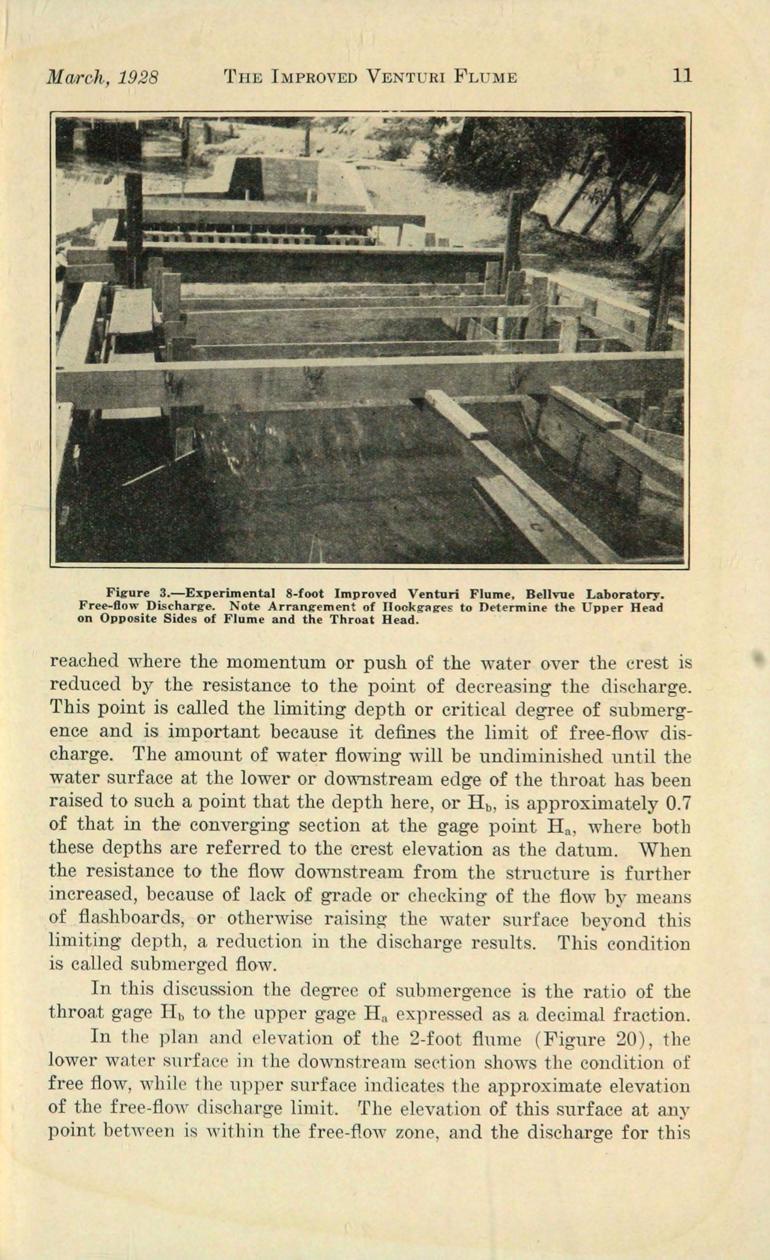
10 10 COLORADO AGRICULrrURAL COLLEGE Bul.336 used was based upon the results of Francis' experiments. The larger improved Venturi flumes were built in this concrete channel at a point upstream from the weir box. The water was admitted to this channel at its upper end, thence flowed thru the experimental structures, and finally was carefully measured over the standard weir. Hookgages were mounted on the model structures at such points as permitted careful measurement of the upper head, H a, and throat head, R b The head on the standard weir was determined by means of t\vo hookgage readings on opposite sides of the weir box (Figure 30). All hookgage readings were observed to a limit of accuracy of foot. Downstream from the experimental flumes an adjustable baffle was provided which permitted the regulation of the degree of submergence. At this laboratory, calibrations were made for flows ranging from 5 secondfeet to 90 second-feet. ACTION OF THE I:~IPROVED VENTURI FLUME The fundamental idea dictating the design of the flume is based upon the effect of the increasing velocity in the converging' section, resulting from the constantly decreasing cross-section of the water prism. As the flowing stream reaches the crest, which is the junction of the upper level floor and throat floor, it has virtually attained its maximum velocity. For the free-flow condition, the stream is carried down the inclined floor of the throat and, with the momentum thus acquired, is carried upward over the inclined floor of the diverging section to the exit end of the structure. Because there is no obstruction to the flow as just described, this condition is called free flow, as shown in Figures 3, 11, 20 and 21. When the resistance to the flowing water in the channel downstream from the flume is great enough, the momentum thru the throat section is not sufficient to permit clearing smoothly in the diverging section. By thus restricting the flow, the water surface is raised in the exit end of the flume. In this transition of flow, the phenomenon occurs known as the "hydraulic jui11p." Because of the downward inclined floor of the throat section, this jump is produced at some distance downstream from the crest, and is, in effect, the means of warding off or holding back the resisting water in the diverging section. In the formation of the hydraulic jump, a portion of the velocity head of the stream passing the crest is converted into static head, which causes the stream to flow at a slower velocity but with greater depth beyond the point Where the jump is formed. 1\.8 the resistance to the flow in the diverging section is further increased, the jump is reduced in its effectiveness and at the same time crowded back into the throat section. As the jump moves upstream into the throat section, a condition of downstream depth is
11

12 12 COLORADO AGRICULTURAL COLLEGE Rul.336 range is a function of the flume '8 width or size and of the upper head, H a, which is measured at the two-thirds point along the converging side of the structure. CHARACTERISTICS OF THE FLUME.-The practical use of the improved Venturi flume has demonstrated that it possesses many desirable characteristics and is not subject to many of the disadvantages of other devices. It may be operated either as a free-flow, single-head device, or under submerged-flow conditions where two heads are involved. Because of the contracted section at the throat, the velocity of water flowing thru the structure is relatively greater than the natural flow of the stream, and for this reason any sand or silt in suspension or rolled along the bottom of the channel is carried thru, leaving the device free of deposit. \Telocity of approach, which often becomes a serious factor in the operation of weirs, has little or no effect upon the rate of discharge of the flume. It is accurate enough for all irrigation purposes and since it remains clear of sediment the reliability of its measurement is believed to be greater than that of other devices. Usually, conditions found in the field will permit it to operate with a free-flow discharge, which is a function only of a single depth, as with a weir. 'I'he loss of head for the free-flow limit is found to be about 25 percent of that for the standard overpour weir. 'There is no easy way to alter the dimensions or cause a change in the device, modify the channel above or below the structure, or otherwise interfere with the original conditions for the purpose of increasing the discharge to effect a wilfully unfair measurement. The design and action of this device have shown that it is capable of withstanding a high degree of submergence before the rate of discharge is reduced. Because of this fact it will operate successfully where the overpour weir fails because of the flat grade of the channel...a. wide range of capacity of measurement has been provided in its calibration, a.nd it is, therefore, adapted to use on the small farm lateral as well as channels of large capacity. The structure itself may be built of either wood or concrete, or, for the smaller flumes, of sheetmetal, The fact that the design specifies certain angles does not greatly increase the work of building, since all surfaces are plane; hence the material may be readily cut to fit properly. The practical operation of the device is simple, and any observer can make the necessary readings and apply them to the table and diagrams to determine the discharge. When the discharge is a function of a single depth, a graduated metal tape showing the flow in second-feet, miner's inches, or shares may be installed so that the discharge may be read direct. For this same condition of flow, that is, a single head as a function of the discharge, an integrating instrument operated by means of a float may be mounted over the stilling-well, which will

13 March, 1928 THE IMPROVED VENTURI FJ.JUlVIE 17 positive including all values between +0.6 and +1.5 inclusive, and 1 percent negative all values between -1.4 and -0.5 inclusive. On this same basis the range of positive and negative values was extended to account for all the free-flow observations on the 1, 2, 3, 4, 6, and 8-foot flumes. (4) The height, or ordinate of the bars in the error diagram, Figure 4, shows the percentage of the total of 298 tests, limited in head, H a, from 0.2 foot to 2.5 feet and with the limiting degree of submergence of 69.9 percent. For the distribution of the original 159 tests, it was found that approximately 97 percent of the total number fell within the limit of ±3 percent of the computed value of the discharge; while for the total of 298 tests, 89 percent were within this limit. When the series of tests, consisting of 139 observations on the 1, 2, 4, 6 and 8-foot flumes, made at the Bellvue laboratory in 1926, was included with the original tests, a wider variation of the deviation between the observed and computed discharges was found to exist. In the original series of 1923 there were about twice as many tests made at the Fort Collins hydraulic laboratory, volumetric measurements, on the 1, 2 and 3-foot flumes, as were taken at the Bellvue laboratory. The 1926 tests were all made at the Bellvue laboratory where rectangular weirs, 18 inches, 48 inches and 15 feet in dimensions, were used to determine the observed discharge. (Figure 30.) Table III, giving the free-flow discharge in second-feet thru the improved Venturi flume for sizes from 1 foot to 10 feet, is based on the formula Q=4 W H W O 0')6 a. ~. OJ Figures 5 and 6 show field installations of I-foot and 2-foot improved Venturi flumes operating under free-flow conditions, each being equipped with a water-stage recording instrument giving a record of the upper head, H a There is practically no submergence in the case of the I-foot flume, but in the 2-foot structure the degree of submergence is approximately 50 percent for a. discharge of 5.7 second-feet. The loss of head in this structure was determined roughly in the field to be about 4 1 / 2 inches, and by applying the data to the diagram, Figure 15, the loss is calculated to be slightly IIIore than 5 inches. 'Of the total of 308 free-flow tests, two 'were excluded because of gross error, (6512, 3-foot flume, and 7043, 8-foot flume). Six special tests ( , , 2-foot flume, and , 3-foot flume) were excluded. Tests were omitted because the value of H, exceeded 2.5 feet. Summarv as follows: Test W H IRatio Hb IObserved I:::omputed I Differa Hb 'Deviatton H n Q! Q ence Ft. Ft. Ft. Sec.-Ft. SeC.-Ft. SeC.-Ft. Percent ~ : I

14 March, 1928 THE IMPROVED VENTURI FLUME 1-3 accurately record the total discharge in acre-feet for any period of time. Where the flow thru the flume is submerged, and two heads or depths are observed, a graphic recording instrument may be used which indicates on a chart the value of the upper head and the difference in head between this upper depth and the head or depth at the throat. This recorded data, referred to the size of the flume, is sufficient to determine the total flow over any period of time. In the case of the integrating instrument, this total is read directly from a series of dials, while for the recording instrument subsequent calculations are necessary. (See discussion on page 58.) CONSTRUCTION OF EXPERIMENTAL FLUMES AND METHOD OF OBSERVATION The experimental test flumes at both the Fort Collins and Bellvue laboratories were of ordinary lumber. The sills and posts were 2 by 4-inch pieces, while the floor and walls were made of I-inch boards, surfaced on both sides. In the building of these structures particular care was taken to have all dimensions exact. When the side walls and floor became wet they swelled, and due allowance was made in having the throat width or size of flume slightly greater than the nominal length in order that, when the structure was completely soaked, the swelling would bring the dimension close to the true value. Dimensions of the structure were checked occasionally to see whether or not they remained within practical limits. The stilling wells were metal cans, about 10 inches in diameter and from 3 to 6 feet deep. The deeper cans were used at the Bellvue laboratory as a matter of convenience. In the mounting of hookgages, care was taken to have them securely fixed. At the Bellvue laboratory, a 2 by 6-inch plank was set vertically and rigidly fixed to insure against error in depth measurements, as shown in Figure 3. The metal stilling' well was placed against the face of the plank, resting firmly upon a solid base. A ~i-inch pipe connection was provided at the bottom of the well, and from this wa.s led a piece of common garden hose of the same diameter, connecting to the wall of the flume by a similar pipe connection at the desired point. In the concrete channel downstream from the model flume was a 22 by 22-inch metal gate, placed in a framework consisting of a set of flashboards. This ga.te and the fiashboards made it possible to secure various degrees of submergence and to regulate the flow thru the test structure. Baffles were placed upstream from the model flume as well as downstream below the submergence bulkhead. Each morning before operations were begun, all hookgage constants were determined by means of an engineer's level and rod. The

15 14 COLORADO AGRICULTURAL COLLEGE B'ltl.336 mean elevation of the crest of the test flume was accuratly determined by several observations at different points. A light wooden rod with sliding target was placed at a point of mean elevation and the target set exactly at the line of sight of the instrument. This rod was then placed upon the Vari01..1S hooks of the gages and the gages were adjusted so that the target again agreed with the line of sight of the leveling instrument. The hookgage readings then gave the constant of correction for each gage. This same method was employed to determine the hookgage constants for the standard rectangular weirs, Water was admitted to the concrete channel by means of the main regulating gate and after the flow had assumed a constant condition observations were taken as follows: An observer started by reading the upper head, or H a, on the flume, calling this observation to a note-keeper who recorded it on a special form, and then read in proper order all other hookgages, calling the readings as they were observed. For the most part, five hookgages were observed, three on the experimental flume and two on the standard weir. A complete round of readings usually required about one and one-half minutes, and where the variations in the water surface were small, five complete sets were assumed to be sufficient to give the correct mean; otherwise, more observations were taken. In the old type of Venturi flume it was found that the downstream flow conditions were such as to swing the current from one side to the other, apparently without cause. This swinging was found to affect the reading of head in the converging section. To determine whether or not heads observed on either side of the converging section of the improved Venturi flume were the same, approximately 200 observations were made in 1923 by having two hookgage connections, one on each side at the proper point. These observations show that the difference in the two readings was very small, and it can be safely assumed that the upper head, H a, may be observed on either side with equal accuracy. At the Bellvue laboratory, the loss of head thru the flume was determined by staff gages read direct, the zero of the gages being set at the elevation of the floor of the converging section. These gages were so situated that the elevation of the water above and below the flume could be determined quite accurately. At the Fort Collins laboratory, where calibrations were made on the smaller-sized flumes of small discharge, the loss of head was determined by means of hookgage readings. FR,EE-FLOW FORl\iuLA The data upon which the free-flow formula is based consist of discharge in second-feet and the corresponding heads, H a, for 159 tests, where the degree of submergence is less than 70 percent, these
16 . March, 1928 TI-IE IMPROVED "V"ENTURI FLUME 15 tests being divided according to size of flume as follows: Lfoot flume, 27 tests; 2-foot flume, 28 tests; 3-foot flume, 34 tests; 4-foot flume, 21 tests; 6-foot flume, 20 tests, and the 8-foot flume, 29 tests. The data obtained from the tests, when plotted to a logarithmic scale for the various discharges and corresponding heads, showed very nearly a straight-line variation for the various sizes of flumes tested. Upon adjusting a straight line to these individual sets of plottings, it was observed that the discharge intercepts for the upper head, H a, at one foot are very closely proportional to four times the width of the flume in feet. The slope of the lines for the various sizes of flume is not the same, thus showing that the values of the exponent of the upper head, ITa, are not identical, and therefore vary with the width or size of flume. By careful inspection of the plotted data, values of the intercept and slope have been determined for each size of flume, as given in Table II. TABLE II.---Values of Intercept J and Slope n, Log Plot, for Law of Free-flow Discharge Thru Different-sized Irnproved Venturi Flumes COEFFICIENT J EXPONENT n of He. Size of Flunle W Intercept Log plot Computed II' "Value 4W Difference I Scaled Value I Log plot : Computed Value of 1.522W Difference ~eet I i I The fundamental law for the Iree-fiow discharge thru the improved Venturi flume is: Q=J Han where Q=Quantity in second-feet J=Coefficient which is.a function of the size of the flume Ha=The upper head in feet observed at a point distant upstream from the crest two-thirds the length of the converging section 1'~=Exponent of the head, H, By inspection of the data in Table II, it is evident that, as an approximation, J =4 W, where VV is the size of flume or width of throat, in feet. The relation of the slope 110, and width of flume W has been established as n=1.522w. n.026 Hence. the complete Iormula may be stated as Q=4 W rr,1.522'v o. 026
17 16 COLORADO AGRICULTURAL COLLEGE Bul.336 The form of expression employing the double exponent of H, may at first appear to be complicated and unusual. However, when the simple operation is performed to reduce to the proper value of the exponent for the particular width of flume, the form of the expression for the discharge offers no more difficulty in its solution than the simple discharge formula for a standard weir or submerged orifice. This equation, being in the product form, is readily solved by means of logarithms. Figure 4 shows graphically the agreement of.the computed discharge, as determined by the free-flow formula, with the observed discharge as the base. This comparison includes, in addition to the 26 CJ)... (J) ẉ... LL oa: w m /8 ~ ~ ::> ẕ.j 16 /4 ~ o... LL o } z w o ct w JO 8 6 ~- ~~ ~/ ~~, ~0 :/j '% / --~ -----_._--- 4 :I ~< / ~ : ~ ~; 2 ~ ~;i ~~ :::-: r:m ~ ~~ ~~; %: ~l P.77]~ f':'"'7l o o II NEGATIVE POSITIVE PER CENT DEVIATION Figure 4.-Comparison in Percentage of Computed to Observed Free-flow Discharge Thru Experimental Flumes original tests made in 1923, the 139 check tests made in The data upon which this diagram is based were developed by expressing the deviation between the observed and computed discharge in percentage where the computed was greater than the observed discharge, the percentage was positive, and where the computed was less than the observed discharge the percentage was negative. A tabulation was then made of these values, in which zero deviation included all values between -0.4 and +0.5 inclusive; 1 percent

18
19
20
21

22
23

24
25
26
27
28

29
30
31

32
33
34
35

36
37
38
39
40
41
42
43

44 March, 1928 THE IMPROVED VENTURI FLUME 41 feet. In this case the structure would have to be raised 0.7- foot; that is, 2.5 feet minus 1.8 feet. Since the crest of the flume is 0.25 foot or 3 inches above the end of the outlet floor, the crest is 0.95 foot above the bottom of the channel. The depth of water in the channel being 2.5 feet and the loss of head 0.7 foot, gives a depth of 3.2 feet upstream from the flume, it being assumed that the bottom of the channel is level for the distance occupied by the structure. Since the level floor of the upstream or converging section of the flume is set up 0.95 foot above the bottom, the depth of water upstream now referred to this floor or crest would be 2.25 feet. For the discharge of 70 second-feet at a submergence of 70 percent or less, it is found in Table III that the corresponding II a is 1.96 feet. This head subtracted from the depth 2.25 feet gives 0.29 foot, or the loss in head at gage H a If the materials of which the channel is composed will not withstand the velocity resulting from a submergence of 70 percent, or the increase in depth of water above the structure would require considerable expense in raising the banks to a safe height, then a higher degree of suhmergence will be necessary. For the above conditions of channel and flow, what would be the effect of installing an 8-foot flume ~ Referring to Figure 19 it is found that if this structure be built with a floor of the outlet end of the t;j 2.5 W LL W 2.0 ~ :::>..J u, J.S ~ s WlD 0: 1.0 ~ 0.9 j~ 0.8 ~.0.7 ~ 0.6 a. ~ o ~oz JGe~~V:~r--. ~o 1~ ~ t------bc I ~r:: :--... ~ ",0 <; -v'o t--~ r-- r r-, ~ r--~v~ K ~ ;2: ~k l/"""--... ~.:::" ~o r-r r>< [>t~ 1/ r- r-,~ <9 p O ~ v~ tp 'seo, r-~ e<:- -;~!Je r-... r-, r-, ~(o «~ -- r--ll ~ --"::::"~nd /v 10k. - ~ /'<, ~ /' ~'( /~ / p...,...o r---~i --~r--f-.. / I----V '5<: /...J>~o <; /"" ~,\o~v ~:P ~ / V<S IS LOSS IN HEAD, FEET -~<--- -: ':><: Figure 19.-Loss-of-head Diagram for the 8-foot Improved Venturi Flume flume at the bottom of the channel, or at the depth of 2.5 feet, the degree of submergence will be slightly in excess of 95 percent, or beyond the recommended limit. For this setting, the loss of head will be 0.10 foot. To have a loss of head of 0.25 foot, as in the first case of the 6-foot flume, the depth of water below the flume would need to be 1.9 feet; the lower end of the outlet floor of the flume would be set 0.6 foot above the bottom, and the crest elevation would be 0.85 foot above the bottom, To operate this larger flume at a submergence of 70 percent, it is found from the loss-of-head diagram that the depth

45 42 COLORADO AGRICULTURAL COLLEGE Bul.336 below the flume would have to be 1.5 feet, or the end of the outlet floor would be 1.0 foot above the bottom and the crest or elevation of the level floor of the converging section would be 1.25 feet above the bottom of the channel. With the structure at this elevation, the loss of head or difference in elevation between the upper and lower water surfaces is observed to be approximately 0.5 foot. Assuming that the channel is level for the distance occupied by the structure, the depth of water immediately upstream from the flume will be 3.0 feet. Since the floor of the converging section is set at an elevation of 1.25 feet, it will give a water depth of 1.75 feet when referred to the level floor of the flume. From the free-flow discharge, Table III, it is found that for a discharge of second-feet, the upper head, H a, is 1.63 feet, thus giving a loss of head of only 0.12 foot at gage R a For setting either the 6-foot or 8-foot flume, if no unusual hydraulic characteristics affect the channel downstream. from the structure, the depth in the channel below the structure will increase faster than the head, R a, in the converging section of the flume, It appears that as the discharge decreases from a maximum of 70 secondfeet with a submergence of 70 percent, the percentage of submergence also decreases, which permits the flume to function properly as a single-head device thru the full range of the discharge. Slightly more material would be required to construct the 8-foot flume, but other things being equal, the wing walls would require less material. As previously determined, the loss of head thru the 8-foot flume is 0.2 foot less than for the 6-foot flume; however, this small difference may not be of serious consequence. The 8-foot flume is advantageous, since, with the lower exit velocity there would be less erosion in the channel immediately downstream. If the materials of the channel will withstand the imposed velocities and sufficient free-board is available, the 6-foot flume should be chosen for free-flow discharge or degree of submergence of 70 percent. If the loss of head is too great thru this smaller flume, the loss may be reduced by installing the 8-foot flume. If free-flow conditions are not permissible in either case, because of excessive erosion, then the 6-foot structure should be built and so set in elevation that the resulting submergence will be the least, consistent with safe exit velocity. After having fully decided upon the location of the flume, its size, and the elevation of the crest which will insure that the flume will operate at free-flow or some predetermined degree of submergence, consideration must be given to the fixing of the longitudinal axis of the structure. The site of the flume should be in a reasonably straight section of the channel. It is suggested that a stake be set in the middle

46 March, 1928 'rile IMPROVED VENTURI FLU~IE 43 of the channel 100 feet upstream, and another at the same distance downstream, from the proposed site. Reference points should then be established at convenient distances near the two ends of the structure and in line with the two more distant points. A line stretched between the two latter points will locate the axis of the flume or the midpoints of the floor sills. For structures of moderate size carrying less than 50 second-feet, possibly no great pains need be taken to have the structure carefully aligned, but for greater discharges care must be taken in order that the flow below the structure will be uniformly distributed thruout the channel. CONSTRUCTION OF THE FLUME 'I'he building- of this structure should offer no great difficulty. No warped surfaces have been introduced into the design other than the suggested curved entrance at the inlet of the large flumes. These structures may be made of lumber, concrete, or sheet metal. Figure 1 suggests a wooden framing for the larger flumes, while for the smaller sizes, Figure 20 illustrates a practical design in which the walls and floor are of I-inch or 2-inch mater-ial, and the sills, posts and ties of 2-by-4-inch pieces. Two-inch commercial lumber is recommended for the floor and "ralls of the larger flumes, while the sills and posts may be of 4-by-4-ineh pieces or heavier, as conditions "Tarrant. In the building of the framed structures it is suggested that the pieces which compose the floor and "ralls be laid with sufficient space between them to allow for swelling- when wet, as otherwise the swelling may be sufficient to warp the surfaces seriously and interfere with the proper functioning of the device. Ordinarily if the cracks between the planks or boards be one-eighth to three-sixteenths inch wide, the swelling will not cause distortion and yet will make a tight joint. Let it be assumed that the elevation of the crest of the flume has been fixed by the characteristics of the channel in which the flume is to be built. It is then necessary to set the crest sill at its proper elevation, as well as in the correct transverse position. For the smaller sizes, the fact that the longitudinal axis of the structure is not exactlv coincident with that of the channel is of little importance where only moderate flows have to be cared for, but the large flumes should be so set that this axis is approximately correct to permit the stream to approach and leave the structure without undue distortion. lienee the site of the flume should not be in a decided bend of the channel. The crest sill having been set and securely fixed in position, the other floor sills may be placed at their proper intervals and elevations. after which the posts and ties 111ay be set. The posts. must be set
47
48

49
50 March, 1928 THE IMPROVED VENTURI FLUME 47 corner of the angle iron forming the true crest. The stilling wells for the concrete flumes may be of either wood or concrete, and since the water level in the well is the real index to the water surface within the flume itself, it is essential that the leakage be a minimum to insure the correct reading of the effective depth. Wooden stilling wells carefully made, when once tight after swelling, are dependable but can not be expected to last indefinitely. Wells of small cross section are impractical, because of the difficulty experienced in cleaning them. They should be of ample size with the side opposite the flume sloping outward at the top, to permit easy cleaning as well as for easy and accurate reading of a staff gage set on the far side of the well, as shown in Figure 22. Figure 22.-Suggested Construction of Open Stilling-well with Staff Gage or Scale Inside the Well. For the 6-inch and I-foot flumes, where a number are to be installed, precast concrete members may be' made and installed in the field. To accomplish this, the design for the casting of the several pieces must be such that each will not be too heavy to be handled conveniently. It is recommended that the floor of the converging or upstream section and the floor of the throat section be cast as one piece, with a light angle-iron cast into the face at the crest. A rib should be cast longitudinally along the center line on the bottom side to strengthen the members while they are being handled, and a groove should be formed at the proper distance along the sides, top face, to locate and fix the position of the side walls. Each of these side walls should be cast as a flat slab of the proper dimensions with a projecting tongue on the sides to engage the grooves of adjacent members, Stub bolts cast into the top face of wall members will fix crossbars or struts to resist displacement after the structure has been assembled. Tubes should be cast at the proper points, both in the converging and throat
 set to fit the tube connections, or for moderate depths of flow, they may be of ordinary sewer tile set into a concrete base with the connecting tube")
51 48 COLORADO AGRIC1JL'l'URAL COLLEGE B1lrl.336 walls, to which stilling wells may be attached for the measurement of heads. The wells may be made of lumber (F'igure 9) set to fit the tube connections, or for moderate depths of flow, they may be of ordinary sewer tile set into a concrete base with the connecting tube reaching thru a hole in the side. (Sections of old stave pipe may be used as stilling wells.) This arrangement will not permit the use of a vertical scale in the tile or pipe to determine the head, but a scale measuring down to the water surface from a fixed point at the top may be used. This distance subtracted from the elevation of the fixed point above the crest of the flume will give the effective head. In building a concrete flume in place, a suitable foundation is first prepared in the bottom of the channel. The forms for the floor are set to a grade such that, when struck off, the floor of the eonverging section is level and the floor of the throat and diverging section have properly inclined slopes. For all structures built in a channel, it is necessary to guard against the possibility of the water washing beneath the structure. It is recommended that in preparing the foundtion a trench be cut crosswise, which, when filled with concrete, will form a cut-off wall at each end of the structure and be made a part of the floor itself, and the concrete wings be set down deep enough and into the banks far enough to prevent the water from cutting around the sides. The lower parts of the wing walls should be cast at the same time as the floor system. In building small structures, before the concrete sets, short pieces of reinforcing bars or scrap iron may be placed at intervals along the edges of the floor in such manner that when the walls are east they will strengthen the structure against possible cracking or rupturing at the floor line. After the floor has set hard enough to permit work to be done on it, the forms for the side walls are placed and braced securely to prevent possible displacement. Before pouring the walls, the surface of the floor which is in',contact with the new wall should be cleaned thoroly in order that a proper bond may be secured. The smaller sizes of flumes may be made of sheet metal, as shown in Figure 23. This 6-ineh flume was assembled in the shop ready for setting in the field. It was built rigidly of 16-gage galvanized sheet steel and, exclusive of the stilling well, weighed 65 pounds. Small flumes built of sheet metal have long life, are easy to set, may be readily moved and relocated, can not be harmed by burning weeds or trash in ditch-cleaning operations, do not leak, and are easily built true to specified dimensions.

52

53

54

55

56 March, 1928 THE IMPROVED VENTURI FLUME 53 The floor of the channel immediately above the flume structure was built level, of Linch boards, this floor being in reality merely an extension of the floor of the converging section of the experimental flume. Vertical wing walls were placed at an angle of 45 degrees to the longitudinal axis of the flume from the upper ends of its converging section, these wings extending back on each side to the concrete walls of the laboratory channel Movable partitions were set up in a vertical position on the floor of the approach section, one on each side of and parallel to the axis of the channel with the lower or downstream ends against the wings. Tests were made with widths of approach channel varying from a maximum of 11.1 feet to a minimum of 6.0 feet. The results of this series of observations for free-flow conditions are given in 'I'able XIX. In the last column of this table showing ratio of velocities in percentages, it appears that for the narrow channel, 6-foot width, the increase in velocity of approach is practically 85 percent of that for the standard condition of 11.1 feet. To determine these values, the velocity of approach in feet per second was carefully plotted against the upper head, H a, where the width of channel was 11.1 feet. The mean curve was drawn thru these points, which gave the values near 100 percent as indicated. Then for the other widths of channel, the velocity of approach for the corresponding head was determined from this mean curve and this value was compared with the actual velocity of approach. These tests indicate that the maximum increase of 85 percent in the velocity of approach does not cause a significant change in the discharge, as the variation is less than the experimental error. The effect on the discharge over standard weirs caused by filling the basin upstream from the crest with sediment or deposit, or reducing this depth by improper construction, possibly may not be fully appreciated. For proper measurement by the use of the standard overpour weir, it has been found by experiment that the bottom depth or vertical distance from the crest to bottom should equal twice the maximum head, and the distance out to the sides of the box or banks be equal to three times this head; or the bottom depth be three times the head and the side or end distance be twice the head. With these limitations of bottom and side distances, the velocity of approach should be about one-third foot per second, and the error from this source about 1 percent of the discharge. To take the extreme case where the bottom and side distance are each one-half foot for a I-foot rectangular weir with a head of 0.6 foot, the error in discharge due to the velocity of approach is found to be 4.6 percent. For these same distances and head, but with a 4-foot rectangular weir, the error in discharge is' 10.5 percent. For a I-foot and a 4-foot weir, with 1
57
58

59 56 COLORADO AGRICULTURAL COLLEGE Bul.336 foot head and the bottom and side distances each at 1 foot the error in discharge is 2.8 percent and 6.8 percent, respectively. As the head increases, the error also increases, assuming the bottom and side distances to remain fixed. For this fixed condition the error in creases as the length of crest is increased. COMPARISON OF Loss OF HEAD FOR VARIOUS DISCHARGES OVER STANDARD WEIRS AND THR1J THE IMPROVED VENTURI FLUME 'I'able XX has been prepared to show the relative loss of head in feet for various discharges thru the improved Venturi flume and over weirs. For the 6-inch flume the degree of submergence at 50 percent was taken as the limit of free-flow, while for the 1, 2 and 4-foot flumes the limiting percentage was taken at 70. It is to be noted in this comparison that the values given under the headings for the various weirs represent the actual head on the crest to give the corresponding discharge. The loss of head is, in reality, greater than that indicated by the distance between the water surface downstream from the weir and the crest. This additional fall is necessary to permit the free passage of air underneath the nappe, or overpouring stream of water, and may be assumed to be from 0.05 to 0.10 foot. ACCESSORIES The discha.rge-indicating tape is graduated according to the freeflow discharge formula and may show either cubic-feet per second, miner's inches, rights or shares, for equal increments in depth, or it may be graduated in cubic-feet per second, miner's inches, or shares as whole numbers, the increment in depth decreasing as this depth increases. The principle of this device is shown in Figure 1. The graduated metal tape, passing over the flat-faced wheel, is directly under a fixed index or pointer observed thru a small opening which permits accuracy and ease in reading. With this arrangement, the amount of discharge may be read directly from the tape. As the moving system is a unit, it will not get out of order. The numbers showing the value of the graduations should be outlined by perforations, thus insuring against obliteration by wear or erasure or fraudulent changing of the number. The stilling well as designed and shown in Figure 22 features a very desirable improvement over the old straight well, as the inclined wall makes cleaning easy. Sediment which accumulates in the stilling well is deposited in a space provided below the inlet tube. The process of cleaning is accomplished by raising a hinged lid and drawing the deposit upward along the inclined side

60

61
62

63

64 March, 1928 THE IMPROVED VENTURI FLUME 61 observed discharge, Figure 29. Tests 7555 to 7615 were also made at the Bellvue laboratory, but apply to a different device. A standard 4-foot rectangular weir was used in tests 7616 to 7712, Figure 30, while for tests 7713 to 7756 an IS-inch rectangular weir was used. Tests 7757 to 7773 were made where the 15-foot weir was used to determine the discharge. It will be found for tests on the 2-foot flume that four different-sized weirs, as well as volumetric determinations of discharge, were used in the calibration. The computed discharges for tests 7674 to 7683, I-foot flume, were reduced by 2 percent because the dimension of width of throat was incorrect. - Tests 7379 to 7388 were made on the 8-foot improved Venturi flume as special observations to determine the effect of increasing the length of the converging section of the structure. In this case the length of side was increased from the standard dimension of 8 feet to 14.5 feet. This increase of length of side gave a width of structure at the front end of 14.0 feet. It will be noted that the computed discharges for both the free-flow and submerged flow agree quite closely with the observed discharge, The hydraulic condition of flow within or thru this setting was very good. See 'I'able XXXV. The series of tests at the Bellvue laboratory in 1923 was for the most part made with duplicate readings of the upper head, H a, on the model flumes; that is, the head was determined at corresponding points on opposite sides of the converging section and the value of the mean used as the effective head. The throat head, H b, was a single determination. The 1926 series of tests at the Bellvue laboratory was made with duplicate readings of both H, and H; and the means determined as the effective heads. It was found that the upper head, H n, as observed on either side of the flume, gave very consistent agreement, while the two throat gages gave results that were more discordant. Examination of the mean values of H, shows that for the 8-foot flume these differ as a maximum as much as 0.07 foot for a discharge of 80 second-feet, and for submergence between 50 and 80 percent. These maximum differences in the H, mean readings indicate that one gage was consistently high, but in general it was found that either one may be greater. As the size of flume decreases the maximum difference in the throat gages also decreases, but the tendency is for greater differences to show for the lower degree of submergence. These inconsistencies under laboratory settings would warrant the conclusion that for field conditions where only approximate methods are used to determine the heads, an accurate determination of the computed submerged-flow discharge would not be expected. However, it is believed on the whole, that submerged-flow measure-

65 62 COLORADO AGRICULTURAL COLLEGE Bul.336 ments in the field are possible, allowing" for these apparent inconsistencies of the throat-gage reading. The first nine tests, free-flow, on the 8-foot flume, series of 1926, showed a difference of 0.03 to 0.05 foot in the H, gages. Examination of the floor disclosed an irregularity near the gage opening at one side. The removal of this obstruction appeared to correct the difficulty, and thereafter very close agreement with the opposite, H a, reading was obtained. Elevations taken on the crest of this 8-foot flume at the beginning showed one end to be approximately 0.03 foot low, Commencing with test 7310, the floor in the converging section had been removed and the crest adjusted to within about foot. Free-flow discharge for succeeding tests showed better agreement. The general trend of all tests on this 8-foot setting was for the observed discharge, as determined by the 15-foot standard rectangular weir, to be in excess of the computed discharge. The mean width of throat at the conclusion of test 7388 was 7.98 feet. Computed discharges for this 8-foot setting were corrected accordingly. After completing the tests on the 4-foot flume the apparatus was again adjusted to an 8-foot size and tests 7518 to 7554 were made. This short series shows a better agreement between the computed and observed discharges. Tests on the 6-foot flume, 7389 to 7455, series of 1926, show fair agreement. These tests were made by four different observers. For discharges of 75 to '85 second-feet, free-flow, the contraction effect caused by the water flowing past the upstream end of the converging section resulted in a pronounced dip or depression at the point vertically above the piezometer opening to H, gage stilling wells. This depression was estimated to be about 3 inches below the general slope of the inclined water surface. The law of the discharge is based upon stilling-well depths, and the fact that the static head is reduced by the contraction does not vitiate the results of this seemingly' erratic condition. Gage staffs or scales placed on the inside face of the converging section to permit the head, H a, to be read would be unsatisfactory for large free-flow discharges. For the 4-foot settings, test 7501, the discharge was free-flow; that is, unrestricted by back water, similar to that shown in Figure 3. This test showed a gage ratio of approximately 74 percent, and even tho being strictly free flow it was classified as a. submerged test and corrected accordingly. At this discharge the throat was filled to such an extent that the gage at this point registered a depth of more than the freo-ftow limit. Had this test been considered as free-flow, the deviation between the observed and computed discharges would have been approxiluately 1.1 percent.

66 Ma.rch, 1928 TI-IE IlVIPROVED VENTURI FLUJYIE 63 Profiles of the water surfaces were taken along the longitudinal axis of the flume for tests It was found for these tests that the gage, H a, agreed reasonably well with measured depth in the flume; however, in all cases the stilling-well depth exceeded the profile in amounts ranging from 0.01 to 0.03 foot. Greater variation was found to exist in the H, hookgage readings. Nothing of unusual importance "vas observed in connection with these tests on the 2-foot flume. Test 7763, free-flow discharge, gave the maximum flow thru this size structure in 1926, this test being limited to the total supply available in the river. At the Bellvue laboratory in 1923, a test was made on the 2-foot fiu111e where the l1pper head, H a, was 2.65 feet and the gage ratio 72 pereent. This condition of flow was similar to test 7501 for the 4-foot flume. Assuming the eondition as free-flow, it was found that the deviation of computed and observed diseharge was approximately 1.1 percent, the computed discharge being in excess for both these maximum flows. It was found in testing the I-foot flume that the computed discharges for tests 7674 to 7683 had to be reduced by 2 percent, due to reduction in mean length of crest. Ice was a troublesome factor at the Bellvue laboratory in 1926 during the time tests were being made on the I-foot and 2-foot flumes. It is believed, however, that it had little or no effect upon the accuracy of the work.. SUMJ\IARY The improved Venturi flume has shown in field operation that it. is practical under conditions which make a standard weir or rating flume impractical, either because of silting trouble or insufficient grade. The accuracy of measurement with this device is entirely within practical limits. The observed discharge, free-flow, was within ±3 percent of the computed amount in 89 percent of the tests. For the submerged flow, 85 percent of the observed discharges were within ±5 percent of the computed amounts. The range of capacity of discharge from a minimum of less than 0.10 second-foot thru the 6-inch flume to a maximum of 200 secondfeet thru the 10-foot flume, as limited by present investigations, is sufficient to meet ordinary requirements. This device operates successfully with relatively small loss of head, and for free flow this loss in a. standard weir is approximately four times that in the flume. The flume will withstand a high degree of submergence without affecting the rate of free-flow discharge.
Broadly speaking, there are four different types of structures, each with its own particular function:
 3 The selection of structures 3.1 Introduction In selecting a suitable structure to measure or regulate the flow rate in open channels, all demands that will be made upon the structure should be listed.
Measuring Water with Parshall Flumes
 Utah State University DigitalCommons@USU Reports Utah Water Research Laboratory January 1966 Measuring Water with Parshall Flumes Gaylord V. Skogerboe M. Leon Hyatt Joe D. England J. Raymond Johnson Follow
SUBMERGED VENTURI FLUME. Tom Gill 1 Robert Einhellig 2 ABSTRACT
 SUBMERGED VENTURI FLUME Tom Gill 1 Robert Einhellig 2 ABSTRACT Improvement in canal operating efficiency begins with establishing the ability to measure flow at key points in the delivery system. The lack
Lecture 10 : Sewer Appurtenances
 1 P age Module 8 : Sewer Appurtenances Lecture 10 : Sewer Appurtenances 2 P age The structures, which are constructed at suitable intervals along the sewerage system to help its efficient operation and
3. GRADUALLY-VARIED FLOW (GVF) AUTUMN 2018
 AUTUMN 2018") 3. GRADUALLY-VARIED FLOW (GVF) AUTUMN 2018 3.1 Normal Flow vs Gradually-Varied Flow V 2 /2g EGL (energy grade line) Friction slope S f h Geometric slope S 0 In flow the downslope component of weight balances
3. GRADUALLY-VARIED FLOW (GVF) AUTUMN 2018 3.1 Normal Flow vs Gradually-Varied Flow V 2 /2g EGL (energy grade line) Friction slope S f h Geometric slope S 0 In flow the downslope component of weight balances
TM /AFM 88-5, Chap Underground hydraulic design Inlets UFC - Drainage In Areas Other Than Airfields
 sults of laboratory research concerning soil infiltration through pipe joints and the effectiveness of gasketing tapes for waterproofing joints and seams are available. 3 6. Underground hydraulic design.
APPENDIX B HYDRAULIC DESIGN DATA FOR CULVERTS
 TM 5-820-4/AFM 88-5, Chap 4 APPENDIX B HYDRAULIC DESIGN DATA FOR CULVERTS B-1. General. a. This appendix presents diagrams, charts, coefficients and related information useful in design of culverts. The
Experiment (13): Flow channel
: Flow channel") Experiment (13): Flow channel Introduction: An open channel is a duct in which the liquid flows with a free surface exposed to atmospheric pressure. Along the length of the duct, the pressure at the surface
Experiment (13): Flow channel Introduction: An open channel is a duct in which the liquid flows with a free surface exposed to atmospheric pressure. Along the length of the duct, the pressure at the surface
ANSWERS TO QUESTIONS IN THE NOTES AUTUMN 2018
 ANSWERS TO QUESTIONS IN THE NOTES AUTUMN 2018 Section 1.2 Example. The discharge in a channel with bottom width 3 m is 12 m 3 s 1. If Manning s n is 0.013 m -1/3 s and the streamwise slope is 1 in 200,
Transition Submergence and Hysteresis Effects in Three-Foot Cutthroat Flumes
 Transition Submergence and Hysteresis Effects in Three-Foot Cutthroat Flumes Why Measure Water for Irrigation? (You had to ask.) Improve: Accuracy Convenience Economics Water Measurement Manual (Door Prize)
Design Data 22M. Flotation of Circular Concrete Pipe. w w I = w - x 1000 (3) (SG x 1000)
 (SG x 1000)") Design Data M Flotation of Circular Concrete Pipe There are several installation conditions where there is the possibility that concrete pipe may float even though the density of concrete is approximately.4
Design Data M Flotation of Circular Concrete Pipe There are several installation conditions where there is the possibility that concrete pipe may float even though the density of concrete is approximately.4
Sediment Basin 7E-12. Design Manual Chapter 7 - Erosion and Sediment Control 7E - Design Information for ESC Measures BENEFITS.
 7E-12 Design Manual Chapter 7 - Erosion and Sediment Control 7E - Design Information for ESC Measures Sediment Basin BENEFITS Flow Control Erosion Control Sediment Control Runoff Reduction Flow Diversion
Simple Flow Measurement Devices for Open Channels
 Simple Flow Measurement Devices for Open Channels Seth Davis, Graduate Student deedz@nmsu.edu Zohrab Samani, Foreman Professor zsamani@nmsu.edu Civil Engineering Department, New Mexico State University
Item 404 Driving Piling
 Item Driving Piling 1. DESCRIPTION Drive piling. 2. EQUIPMENT 2.1. Driving Equipment. Use power hammers for driving piling with specified bearing resistance. Use power hammers that comply with Table 1.
SIZING AND CAPACITIES OF GAS PIPING
 SIZING AND CAPACITIES OF GAS PIPING A.1 General piping considerations. The first goal of determining the pipe sizing for a fuel gas piping system is to make sure that there is sufficient gas pressure at
Experiment 8: Minor Losses
 Experiment 8: Minor Losses Purpose: To determine the loss factors for flow through a range of pipe fittings including bends, a contraction, an enlargement and a gate-valve. Introduction: Energy losses
COMPARING PLUG & SEAT REGULATORS & CONTROL VALVES. Lamar Jones. Equipment Controls Company 4555 South Berkeley Lake Road Norcross, GA 30071
 COMPARING PLUG & SEAT REGULATORS & CONTROL VALVES Lamar Jones Equipment Controls Company 4555 South Berkeley Lake Road Norcross, GA 30071 INTRODUCTION The purpose of this paper will be to compare a plug
LoneStar Fiberglass Pools. Do-It-Yourself. Installation Manual
 LoneStar Fiberglass Pools Do-It-Yourself Installation Manual Chris 1/3/2008 Do-It-Yourself The installation of a LoneStar Fiberglass pool is a much simpler task than most people think. What is important
SIZING AND CAPACITIES OF GAS PIPING
 APPENDIX A (IFGS) SIZING AND CAPACITIES OF GAS PIPING (This appendix is adopted as part of the code.) A.1 General. To determine the size of piping used in a gas piping system, the following factors must
A A A T E C H N O L O G Y
 A A A T E C H N O L O G Y & SPECIALTIES CO., INC. C O N S T A N T E F F O R T S U P P O R T S TOTAL SOLUTION SERVICE For the Industrial Piping Marketplace 2012 www.aaatech.com 4 1 Y E A R S S E R V I N
FUNDAMENTALS OF PRESSURE REGULATORS ROBERT BENNETT MANAGER OF TRAINING ELSTER AMERICAN METER
 FUNDAMENTALS OF PRESSURE REGULATORS ROBERT BENNETT MANAGER OF TRAINING ELSTER AMERICAN METER SUPPLY = DEMAND FUNCTION OF A REGULATOR A regulator may be defined as a "mechanism for controlling or governing
The Discussion of this exercise covers the following points:
 Exercise 3-2 Orifice Plates EXERCISE OBJECTIVE In this exercise, you will study how differential pressure flowmeters operate. You will describe the relationship between the flow rate and the pressure drop
Cover Page for Lab Report Group Portion. Head Losses in Pipes
 Cover Page for Lab Report Group Portion Head Losses in Pipes Prepared by Professor J. M. Cimbala, Penn State University Latest revision: 02 February 2012 Name 1: Name 2: Name 3: [Name 4: ] Date: Section
Practical Guide. By Steven T. Taylor, P.E., Member ASHRAE
 ractical Guide The following article was published in ASHRAE Journal, March 2003. Copyright 2003 American Society of Heating, Refrigerating and Air- Conditioning Engineers, Inc. It is presented for educational
THE WAY THE VENTURI AND ORIFICES WORK
 Manual M000 rev0 03/00 THE WAY THE VENTURI AND ORIFICES WORK CHAPTER All industrial combustion systems are made up of 3 main parts: ) The mixer which mixes fuel gas with combustion air in the correct ratio
IMPACT OF MAKING THE CREST OF WEIR MULTIFACETED ON DISCHARGE COEFFICIENT OF MORNING GLORY SPILLWAY
 IMPACT OF MAKING THE CREST OF WEIR MULTIFACETED ON DISCHARGE COEFFICIENT OF MORNING GLORY SPILLWAY Ali Bagheri 1 and *Ebrahim Nohani 2 1 Department of Water Engineering, Qaemshahr Branch, Islamic Azad
VACUUM TESTING PRECAST CONCRETE MANHOLES
 1 OF 5 testing is a quick, safe and practical way to validate manhole system integrity. Manhole sections can be tested at the precast concrete plant prior to delivery or on site prior to backfilling. Here
Course Teacher: Prof. Dr. M. R. Kabir SPILLWAY & IRRIGATION PUMPS. Spillway:
 Spillway: CHAPTER 10 The spillways are openings provided at the body of the dam to discharge safely the excess water or flood water when the water level rises above the normal pool level. Necessity of
HYDRAULIC JUMP AND WEIR FLOW
 HYDRAULIC JUMP AND WEIR FLOW 1 Condition for formation of hydraulic jump When depth of flow is forced to change from a supercritical depth to a subcritical depth Or Froude number decreases from greater
SIZING AND CAPACITIES OF GAS PIPING
 APPENDIX A (IFGS) SIZING AND CAPACITIES OF GAS PIPING (This appendix is informative and is not part of the code. This appendix is an excerpt from the 2003 International Fuel Gas Code, coordinated with
FUNDAMENTALS OF DIAPHRAGM DISPLACEMENT METERS. Julie Ellington. Itron, Inc. Utility Measurement
 FUNDAMENTALS OF DIAPHRAGM DISPLACEMENT METERS Julie Ellington Itron, Inc. Introduction Natural gas measurement is the vertebrae of any natural gas utility. Without the ability to measure, it would be impossible
STATIONARY SPRINKLER IRRIGATION SYSTEM
 STATIONARY SPRINKLER North Carolina Cooperative Extension Service North Carolina State University STATIONARY SPRINKLER General Guidelines Operating an irrigation system differently than assumed in the
Khosla's theory. After studying a lot of dam failure constructed based on Bligh s theory, Khosla came out with the following;
 Khosla's theory After studying a lot of dam failure constructed based on Bligh s theory, Khosla came out with the following; Following are some of the main points from Khosla's Theory From observation
Operating instructions Pitot Static Tube
 Operating instructions Pitot Static Tube halstrup-walcher GmbH Stegener Straße 10 D-79199 Kirchzarten, Germany Phone: +49 (0) 76 61/39 63-0 Fax: +49 (0) 76 61/39 63-99 E-mail: info@halstrup-walcher.de
HYDROVEX TTT Membrane Flow Regulator
 HYDROVEX TTT Membrane Flow Regulator INSTALLATION, OPERATION AND MAINTENANCE MANUAL PROJECT EQUIPMENT LOCATION EQUIPMENT DESCRIPTION HYDROVEX TTT REFERENCE N OF THE SUPPLIER MODEL N SERIAL N DATE OF FABRICATION
FORMAT FOR SENDING COMMENTS. Title: CRITERIA FOR DESIGN OF CANAL HEAD REGULATORS (Second revision of IS 6531)
") FORMAT FOR SENDING COMMENTS Last Date for Comment is 0 November 009 E-Mail ID for sending comments: rrdash@bis.org.in Document No.: Doc WRD 14 (495)C Title: CRITERIA FOR DESIGN OF CANAL HEAD REGULATORS
FORMAT FOR SENDING COMMENTS Last Date for Comment is 0 November 009 E-Mail ID for sending comments: rrdash@bis.org.in Document No.: Doc WRD 14 (495)C Title: CRITERIA FOR DESIGN OF CANAL HEAD REGULATORS
2. RAPIDLY-VARIED FLOW (RVF) AUTUMN 2018
 AUTUMN 2018") 2. RAPIDLY-VARIED FLOW (RVF) AUTUMN 2018 Rapidly-varied flow is a significant change in water depth over a short distance (a few times water depth). It occurs where there is a local disturbance to the
2. RAPIDLY-VARIED FLOW (RVF) AUTUMN 2018 Rapidly-varied flow is a significant change in water depth over a short distance (a few times water depth). It occurs where there is a local disturbance to the
Effect of Fluid Density and Temperature on Discharge Coefficient of Ogee Spillways Using Physical Models
 RESEARCH ARTICLE Effect of Fluid Density and Temperature on Discharge Coefficient of Ogee Spillways Using Physical Models M. SREENIVASULU REDDY 1 DR Y. RAMALINGA REDDY 2 Assistant Professor, School of
METHODS EMPLOYED IN LOCATING SOUNDINGS
 METHODS EMPLOYED IN LOCATING SOUNDINGS The soundings are located with reference to the shore traverse by observations made (i) entirely from the boat, (ii) entirely from the shore or (iii) from both. The
Cover Page for Lab Report Group Portion. Pump Performance
 Cover Page for Lab Report Group Portion Pump Performance Prepared by Professor J. M. Cimbala, Penn State University Latest revision: 02 March 2012 Name 1: Name 2: Name 3: [Name 4: ] Date: Section number:
(fig. 3) must be at the same temperature as the water in this chamber CALORIMETRIC STUDIES OF THE EXTREMITIES
 must be at the same temperature as the water in this chamber CALORIMETRIC STUDIES OF THE EXTREMITIES") CALORIMETRIC STUDIES OF THE EXTREMITIES II. EXPERIMENTAL APPARATUS AND PROCEDURES' By ROY KEGERREIS (Received for publication July 1, 1926) The calorimeter used in these experiments is a modification of
CALORIMETRIC STUDIES OF THE EXTREMITIES II. EXPERIMENTAL APPARATUS AND PROCEDURES' By ROY KEGERREIS (Received for publication July 1, 1926) The calorimeter used in these experiments is a modification of
COEFFICIENT OF DISCHARGE OF CHIMNEY WEIR UNDER FREE AND SUBMERGED FLOW CONDITIONS
 COEFFICIENT OF DISCHARGE OF CHIMNEY WEIR UNDER FREE AND SUBMERGED FLOW CONDITIONS Hanaa A.M.Hayawi Amal A.G.Yahya Ghania A.M.Hayawi College Of Engineering University Of Mosul Abstract: The main objective
Hours / 100 Marks Seat No.
 17421 21415 3 Hours / 100 Marks Seat No. Instructions : (1) All Questions are compulsory. (2) Answer each next main Question on a new page. (3) Illustrate your answers with neat sketches wherever necessary.
Applied Fluid Mechanics
 Applied Fluid Mechanics 1. The Nature of Fluid and the Study of Fluid Mechanics 2. Viscosity of Fluid 3. Pressure Measurement 4. Forces Due to Static Fluid 5. Buoyancy and Stability 6. Flow of Fluid and
Advanced Hydraulics Prof. Dr. Suresh A. Kartha Department of Civil Engineering Indian Institute of Technology, Guwahati
 Advanced Hydraulics Prof. Dr. Suresh A. Kartha Department of Civil Engineering Indian Institute of Technology, Guwahati Module - 4 Hydraulics Jumps Lecture - 4 Features of Hydraulic Jumps (Refer Slide
Irrigation &Hydraulics Department lb / ft to kg/lit.
 CAIRO UNIVERSITY FLUID MECHANICS Faculty of Engineering nd Year CIVIL ENG. Irrigation &Hydraulics Department 010-011 1. FLUID PROPERTIES 1. Identify the dimensions and units for the following engineering
Air Eliminators and Combination Air Eliminators Strainers
 Description Air Eliminators and Combination Air Eliminator Strainers are designed to provide separation, elimination and prevention of air in piping systems for a variety of installations and conditions.
TOP:001.3 U.S. Fish and Wildlife Service TECHNICAL OPERATING PROCEDURE
 TOP:001.3 March 12, 2015 U.S. Fish and Wildlife Service Marquette Biological Station 3090 Wright Street Marquette, Michigan 49855 U.S.A. and U.S. Fish and Wildlife Service Ludington Biological Station
Impact of imperfect sealing on the flow measurement of natural gas by orifice plates
 Impact of imperfect sealing on the flow measurement of natural gas by orifice plates Rubens Silva Telles 1, Kazuto Kawakita 2 1 IPT Instituto de Pesquisas Tecnológicas, São Paulo, Brazil, rtelles@ipt.br
Exercise (3): Open Channel Flow Rapidly Varied Flow
: Open Channel Flow Rapidly Varied Flow") Exercise (3): Open Channel Flow Rapidly Varied Flow 1) A hydraulic jump exists in a trapezoidal channel having a bed width of 7 m and side slope of 1:1. The flowing discharge is 25 m 3 /sec. Construct
Exercise (3): Open Channel Flow Rapidly Varied Flow 1) A hydraulic jump exists in a trapezoidal channel having a bed width of 7 m and side slope of 1:1. The flowing discharge is 25 m 3 /sec. Construct
Exercise 2-3. Flow Rate and Velocity EXERCISE OBJECTIVE C C C
 Exercise 2-3 EXERCISE OBJECTIVE C C C To describe the operation of a flow control valve; To establish the relationship between flow rate and velocity; To operate meter-in, meter-out, and bypass flow control
January, same manner that stirring a fire hastens its burning.
 January, 1932 9 Checking Gully Erosion on Golf Courses By R. E. Uhland Superintendent, Soil Erosion Experiment Station, Bethany, Mo. No one will deny that good greens and fairways are essential to a good
DAIVÕES DAM SPILLWAY: A NOVEL SOLUTION FOR THE STILLING BASIN
 DAIVÕES DAM SPILLWAY: A NOVEL SOLUTION FOR THE STILLING BASIN Elsa Alves *, Felix Hernando and Rafael Chacón * Laboratório Nacional de Engenharia Civil (LNEC) Av. do Brasil, 101, 1700-066 Lisboa, Portugal
LAB 7. ROTATION. 7.1 Problem. 7.2 Equipment. 7.3 Activities
 LAB 7. ROTATION 7.1 Problem How are quantities of rotational motion defined? What sort of influence changes an object s rotation? How do the quantities of rotational motion operate? 7.2 Equipment plumb
EXAMPLES (OPEN-CHANNEL FLOW) AUTUMN 2018
 AUTUMN 2018") EXAMPLES (OPEN-CHANNEL FLOW) AUTUMN 2018 Normal and Critical Depths Q1. If the discharge in a channel of width 5 m is 20 m 3 s 1 and Manning s n is 0.02 m 1/3 s, find: (a) the normal depth and Froude number
EXAMPLES (OPEN-CHANNEL FLOW) AUTUMN 2018 Normal and Critical Depths Q1. If the discharge in a channel of width 5 m is 20 m 3 s 1 and Manning s n is 0.02 m 1/3 s, find: (a) the normal depth and Froude number
Analysis of Shear Lag in Steel Angle Connectors
 University of New Hampshire University of New Hampshire Scholars' Repository Honors Theses and Capstones Student Scholarship Spring 2013 Analysis of Shear Lag in Steel Angle Connectors Benjamin Sawyer
APPLICATION NOTE. AN-9608 July 2001 SEEPAGE MEASUREMENT IN AN OPEN CHANNEL THROUGH A WEIR
 APPLICATION NOTE AN-9608 July 2001 SEEPAGE MEASUREMENT IN AN OPEN CHANNEL THROUGH A WEIR 1 Introduction Seepage of water through, around or under a dam is expected in all embankment dams and even in concrete
SIZING AND CAPACITIES OF GAS PIPING Reserved
 APPENDIX A (IFGS) SIZING AND CAPACITIES OF GAS PIPING Reserved 2003 INTERNATIONAL RESIDENTIAL CODE 529R APPENDIX A SIZING AND CAPACITIES OF GAS PIPING This page left intentionally blank. 530R 2003 INTERNATIONAL
TEST SPECIFICATION NYT-909-C
 748 Starbuck Ave, Watertown, NY 13601 Phone: +1-315-786-5200 Engineering Fax: +1-315-786-5673 TEST SPECIFICATION NYT-909-C CODE OF TESTS FOR TESTING "AB" TEST RACK P/N 702546 & 702612 ISSUE NO. 5 1.0 THE
Free Surface Flow Simulation with ACUSIM in the Water Industry
 Free Surface Flow Simulation with ACUSIM in the Water Industry Tuan Ta Research Scientist, Innovation, Thames Water Kempton Water Treatment Works, Innovation, Feltham Hill Road, Hanworth, TW13 6XH, UK.
Measurement of court speed and bounce. Rod Cross, Physics Department, Sydney University 2nd July 2006
 1 Measurement of court speed and bounce Rod Cross, Physics Department, Sydney University 2nd July 2006 The speed of a surface refers to the change in ball speed in a direction parallel to the surface.
SECTION PRESSURE TESTING OF PIPING
 SECTION 15044 PRESSURE TESTING OF PIPING PART 1 - GENERAL 1.01 DESCRIPTION A. Scope of Work: This section specifies the leakage and pressure testing of piping. B. Testing Records: PART 2 - PRODUCTS 2.01
OIL SUPPLY SYSTEMS ABOVE 45kW OUTPUT 4.1 Oil Supply
 OIL SUPPLY SYSTEMS ABOVE 45kW OUTPUT 4.1 Oil Supply 4.1.1 General The primary function of a system for handling fuel oil is to transfer oil from the storage tank to the oil burner at specified conditions
AIRFLOW GENERATION IN A TUNNEL USING A SACCARDO VENTILATION SYSTEM AGAINST THE BUOYANCY EFFECT PRODUCED BY A FIRE
 - 247 - AIRFLOW GENERATION IN A TUNNEL USING A SACCARDO VENTILATION SYSTEM AGAINST THE BUOYANCY EFFECT PRODUCED BY A FIRE J D Castro a, C W Pope a and R D Matthews b a Mott MacDonald Ltd, St Anne House,
3-13 UFC - GENERAL PROVISIONS AND GEOMETRIC DESIGN FOR ROADS, STREETS, WALKS, AND OPEN
 maintenance, and erosion. Stability is required to maintain the integrity of the pavement structure, and a slope stability analysis should be conducted for cuts and fills greater than 15 feet. For lower
Exercise (4): Open Channel Flow - Gradually Varied Flow
: Open Channel Flow - Gradually Varied Flow") Exercise (4): Open Channel Flow - Gradually Varied Flow 1) A wide channel consists of three long reaches and has two gates located midway of the first and last reaches. The bed slopes for the three reaches
Exercise (4): Open Channel Flow - Gradually Varied Flow 1) A wide channel consists of three long reaches and has two gates located midway of the first and last reaches. The bed slopes for the three reaches
product manual H-2795 Roll-a-Meter
 11.09 product manual H-2795 Roll-a-Meter Directions The Solution The accuracy of Roll-a-Meter results is not dependent on the correctness of all these factors, but gives directly the percent air in the
(Refer Slide Time: 2:16)
") Fluid Machines. Professor Sankar Kumar Som. Department Of Mechanical Engineering. Indian Institute Of Technology Kharagpur. Lecture-23. Diffuser and Cavitation. Good morning and welcome you all to this
Fluid Machines. Professor Sankar Kumar Som. Department Of Mechanical Engineering. Indian Institute Of Technology Kharagpur. Lecture-23. Diffuser and Cavitation. Good morning and welcome you all to this
BC Ministry of Forests. March Fish Stream Crossing Guidebook. Forest Practices Code of British Columbia.
 FRST 557 Lecture 7c Bridges and Culverts: Water Velocity and Discharge Lesson Background and Overview: The previous two lessons presented methods for estimating water volume flow at a particular site and
Water Weir Flow Controller. Introduction. Safety Precautions. Mounting the Hardware
 57007-88 Introduction Safety Precautions This instruction sheet describes how to set up and use the Hach (Figure 1). A water weir is a device that raises or diverts water to regulate the flow. Hach s water
Spring Loaded Regulators Constant Loaded Regulators Twin Parallel Flow Regulators Field Service Regulators
 Product Line Brochure J0B Effective Date 2/01 Spring Loaded Regulators Constant Loaded Regulators Twin Parallel Flow Regulators Field Service Regulators P R O D U C T L I N E O V E R V I E W Regulator
DESIGN OF BELL-MOUTH SPILLWAY AT BARVI DAM
 DESIGN OF BELL-MOUTH SPILLWAY AT BARVI DAM Akshay Haldankar 1, Mahesh Bhadra 2, Rahul Harad 3, Darpan Kapre 4, Dipali Patil 5 1,2,3,4 Under graduate,dept. of Civil Engineering, DRIEMS Neral. 5Assistant
SPEED SHORE MANUFACTURER S TABULATED DATA "MHS" MODELS. STEEL MANHOLE SHIELDS 4 Single Wall 4 Double Wall 4 Double Wall with Cut-Outs
 SPEED SHORE MANUFACTURER S TABULATED DATA "MHS" MODELS STEEL MANHOLE SHIELDS 4 Single Wall 4 Double Wall 4 Double Wall with Cut-Outs January 01, 2005 3330 S. SAM HOUSTON PKWY E. HOUSTON, TEXAS 77047 Tel:
23 RD INTERNATIONAL SYMPOSIUM ON BALLISTICS TARRAGONA, SPAIN APRIL 2007
 23 RD INTERNATIONAL SYMPOSIUM ON BALLISTICS TARRAGONA, SPAIN 16-20 APRIL 2007 AN INVESTIGATION INTO THE INTERRELATION BETWEEN THE INTERNAL AND EXTERNAL BALLISTICS OF FIRING A TP-T TANK AMMUNITION M. H.
Suitable Applications Check dams may be appropriate in the following situations: To promote sedimentation behind the dam.
 Categories EC Erosion Control SE Sediment Control TC Tracking Control WE Wind Erosion Control Non-Stormwater NS Management Control Waste Management and WM Materials Pollution Control Legend: Primary Category
PHYS 101 Previous Exam Problems
 PHYS 101 Previous Exam Problems CHAPTER 14 Fluids Fluids at rest pressure vs. depth Pascal s principle Archimedes s principle Buoynat forces Fluids in motion: Continuity & Bernoulli equations 1. How deep
In the liquid phase, molecules can flow freely from position. another. A liquid takes the shape of its container. 19.
 In the liquid phase, molecules can flow freely from position to position by sliding over one another. A liquid takes the shape of its container. In the liquid phase, molecules can flow freely from position
Access Management Standards
 Access Management Standards Section 1: Application of Access Standards This chapter describes the Department's access management standards for access connections on the county roadway system. The standards
Revisions to the Regulations for Agility Trials
 Revisions to the Regulations for Agility Trials Effective January 2, 2018 Equipment changes may be done prior to January 2, 2018, but must be completed by January 2, 2018 This insert is issued as a supplement
IMPORTANT: RECEIVING INSTRUCTIONS:
 Instruction Sheet Sidewinder Mechanical Bender IMPORTANT: RECEIVING INSTRUCTIONS: Visually inspect all components for shipping damage. If any shipping damage is found, notify carrier at once.shipping damage
STEEL TRENCH SHIELDS DW MODELS
 STEEL TRENCH SHIELDS DW MODELS 3330 S. SAM HOUSTON PKWY E. HOUSTON, TEXAS 77047 Phone: 713.943.0750 Toll Free: 800.231.6662 Fax: 713. 943.8483 COPYRIGHT, U.S.A., SPEED SHORE CORPORATION, 2009 April 16,
In the liquid phase, molecules can flow freely from position to position by sliding over one another. A liquid takes the shape of its container.
 In the liquid phase, molecules can flow freely from position to position by sliding over one another. A liquid takes the shape of its container. In the liquid phase, molecules can flow freely from position
Outlet Structures T-12
 Description This section provides guidance and details for outlet structures for use primarily with BMPs utilizing sedimentation, (i.e., extended detention basins (EDBs), retention ponds, and constructed
ONSITE PROVING OF GAS METERS. Daniel J. Rudroff WFMS Inc West Bellfort Sugar Land, Texas. Introduction
 ONSITE PROVING OF GAS METERS Daniel J. Rudroff WFMS Inc. 13901 West Bellfort Sugar Land, Texas Introduction With the increased use of Natural Gas as a fuel, and higher natural gas prices buyers and sellers
Paper 2.2. Operation of Ultrasonic Flow Meters at Conditions Different Than Their Calibration
 Paper 2.2 Operation of Ultrasonic Flow Meters at Conditions Different Than Their Calibration Mr William Freund, Daniel Measurement and Control Mr Klaus Zanker, Daniel Measurement and Control Mr Dale Goodson,
General. Rugged, Reliable with Value-added Features. Pipe Sizes. Temperature Limits. Spring Ranges. Buried Service. Increased Outlet Pipe Sizes
 DS-G-REG-13-43-0812-01-A* Model 243-RPC Pilot Operated Regulators Installation and Maintenance Instructions Rugged, Reliable with Value-added Features Genuine, pilot-operated regulators use the same relay
INSTRUCTOR GUIDE REFERENCES: PUMPING APPARATUS DRIVER/OPERATOR HANDBOOK, FIRST EDITION, IFSTA
 TOPIC: RELAY PUMPING OPERATIONS LEVEL OF INSTRUCTION: TIME REQUIRED: ONE HOUR INSTRUCTOR GUIDE MATERIALS: APPROPRIATE AUDIO VISUAL SUPPORT REFERENCES: PUMPING APPARATUS DRIVER/OPERATOR HANDBOOK, FIRST
B L A C K H A L L. larner-johnsonvalve presentation
 larner-johnsonvalve presentation History! The Larner-Johnson valve was originally designed and developed in 1920 s for use on hydraelectric power plants in the U.S.A., where it pioneered the application
FUNDAMENTAL PRINCIPLES OF SELF-OPERATED PRESSURE REDUCING REGULATORS. John R. Anderson Emerson Process Management Fluid Controls Institute
 FUNDAMENTAL PRINCIPLES OF SELF-OPERATED PRESSURE REDUCING REGULATORS John R. Anderson Emerson Process Management Fluid Controls Institute For pressure control in process or utility applications, control
Practice Test FOR GAS POSITIONS APTITUDE BATTERY
 Practice Test FOR GAS POSITIONS APTITUDE BATTERY INTRODUCTION The purpose of this Practice Test is to help you prepare for the Gas Positions Aptitude Battery placement exercise. A sample of questions based
Becker* Products Below Ground Ball Valve Regulators
 GE Oil & Gas Becker* Products Below Ground Ball Valve Regulators Reduce Noise Levels at Large Volume Regulator Stations GE s Becker* Below Ground ball valve regulator has the long-term proven reliability,
Dry Hydrants. The installation of a non-pressurized pipe system into local water sources provides a ready means of supplying water to fire engines.
 Dry Hydrants What is a Dry Hydrant? A dry hydrant is a non-pressurized pipe system permanently installed in existing lakes, ponds and streams that provides a suction supply of water to a fire department
RBC flume. All it takes for environmental research. Contents. 1. Introduction. 2. The flumes of Eijkelkamp Agrisearch Equipment
 13.17.06 RBC flume operating instructions Contents 1. Introduction... 1 2. The flumes of Eijkelkamp Agrisearch Equipment... 1 3. Principles of discharge-measuring flumes... 2 4. Selection and location
Experimental Investigation of Clear-Water Local Scour at Pile Groups
 Experimental Investigation of Clear-Water Local Scour at Pile Groups B. Ataie-Ashtiani 1 and A. A. Beheshti 2 Abstract: Experiments of local scour around pile groups are carried out under steady clear-water
PIG MOTION AND DYNAMICS IN COMPLEX GAS NETWORKS. Dr Aidan O Donoghue, Pipeline Research Limited, Glasgow
 PIG MOTION AND DYNAMICS IN COMPLEX GAS NETWORKS Dr Aidan O Donoghue, Pipeline Research Limited, Glasgow A model to examine pigging and inspection of gas networks with multiple pipelines, connections and
Chadbourne Dam Repair and Fish Barrier
 Chadbourne Dam Repair and Fish Barrier Final Report for the Western Native Trout Initiative Prepared by: Carol Endicott Yellowstone Cutthroat Trout Conservation Biologist Montana Fish, Wildlife & Parks
GEOL 106: Earthquake Country Activity 08: Discharge Measurements. Name: Date:
 Name: Date: Discharge Calculation Discharge = Velocity X Area or Q = VA Calculate the Discharge for the measurements shown at the right. Q = Discharge Measurement Do not collect water samples in the area
CONTROL VALVE WHAT YOU NEED TO LEARN?
 CONTROL VALVE WHAT YOU NEED TO LEARN? i) The control valve characteristics refers to the relationship between the volumetric flowrate F (Y-axis) through the valve AND the valve travel or opening position
City of Cerritos SWIMMING POOL, SPA AND EQUIPMENT APPLICATION. (Please print or type) Name: Phone: ( )
 Name: Phone: ( )") City of Cerritos Civic Center 18125 Bloomfield Avenue P.O. Box 3130 Cerritos, California 90703-3130 Phone: (562) 916-1201 Fax (562) 916-1371 SWIMMING POOL, SPA AND EQUIPMENT APPLICATION (Please print or
City of Cerritos Civic Center 18125 Bloomfield Avenue P.O. Box 3130 Cerritos, California 90703-3130 Phone: (562) 916-1201 Fax (562) 916-1371 SWIMMING POOL, SPA AND EQUIPMENT APPLICATION (Please print or
Components of a Barrage
 Components of a Barrage Definition The only difference between a weir and a barrage is of gates, that is the flow in barrage is regulated by gates and that in weirs, by its crest height. Barrages are costlier