Exercise (4): Open Channel Flow - Gradually Varied Flow
|
|
|
- Garey Merritt
- 5 years ago
- Views:
Transcription
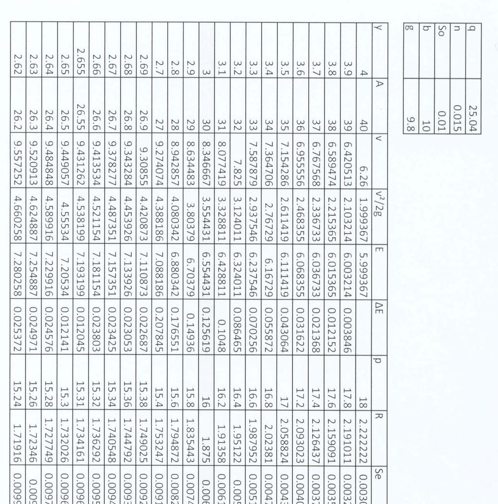
1 Exercise (4): Open Channel Flow - Gradually Varied Flow 1) A wide channel consists of three long reaches and has two gates located midway of the first and last reaches. The bed slopes for the three reaches are S 1 = 0.008, S 2 = , and S 3 = The water discharges to the channel from a lake where the water surface is higher than the normal depth at the inlet. If the discharge is m 3 /sec/m, and n = 0.015, sketch the possible water surface profiles in the channel for the following cases: a) The last reach terminates in a sudden fall. b) The last reach discharges to a lake of water level higher than the normal depth at the exit. 2) Water flows with constant discharge q=1.0 m 3 /s/m into a wide rectangular channel that consists of two very long reaches where the bed slope changes from S o1 =6.87x10⁻³ to S o2 =3.24x10⁻⁴, Calculate: a) The depth of both uniform and critical flow in both reaches (take n=0.018) b) Draw a neat sketch of the water profile at the transition zone and calculate the water depths and the head losses wherever appropriate. 3) A barrage is constructed across a wide river whose discharge is 6 m 3 /sec/m, and bed slope is 10 cm/km. If the afflux produced at the site of the barrage is 3 m, find the length of the water surface profile produced from the site of the barrage till a point where the water depth is 6.25m. Use the approximate method considering 3 points, Chezy coefficient C = 50. 4) A trapezoidal channel of bed width of 7 m, side slopes 3:2, Manning coefficient n of 0.02 is laid on a slope of and carries a discharge of 30m 3 /sec. The channel terminates to a free fall. It is required to compute and plot the water surface profile from downstream to a water depth of 0.9 the normal depth. Use the step by step method (use 3 steps) 5) A steep long channel takes its water from a lake. Prove that the discharge per unit width in the channel is given by: q = 8 27 Two lakes are joined by a wide concrete channel A-B as shown in the figure below, n = The water levels in the lakes are constant. g H a) Find the flow rate into the channel for each of the following bed slopes: i. S o = 10 cm/km ii. S o = iii. S o = 0.01 Compare your results and explain how the flow depth at A affects the flowing discharge. b) Sketch the Water surface profile for the above cases and calculate the water depths wherever appropriate
2 c) Does a hydraulic jump occur? If so, How far upstream point B does it occur? Use the step by step method, considering 5 points. 1.5m A 2.0m n = 0.02, Bed Slope = S o B 6) A 10 m wide, rectangular concrete-lined canal (n = 0.015) has a bottom slope of 0.01 and a constant level lake at the upstream end. The water level in the lake is 6m above the bottom of the canal at the entrance. If the entrance losses are negligible, determine: a) The flow depth 600 m downstream of the channel entrance, b) The distance from the lake where the flow depth is 3.0 m. Use the step by step method. 7) The figure below shows a longitudinal section in a channel of wide cross section. Manning s n = 0.02 and the bed slope is q B A S o = 1/1000, n = 0.02 A gate is located at point A. The discharge equation for the gate in case of free outflow is given by: q = C d 2g( H C d) and for a submerged outflow is: q = Cd d 2g( H y) d c - 2 -
3 Where q is the discharge per unit width (m 2 /sec), C d is the discharge coefficient and is equal to 0.6, d is the height of the gate opening (m), H is the water depth just upstream of the gate (m), y is the water depth downstream the gate (m), and g is the gravitational acceleration (m/sec 2 ). The coefficient of contraction of the gate C c = a) If q = 3 m 3 /sec/m, and H = 3m, find the gate opening d, and check if a free hydraulic jump will form downstream of the gate. Assume the channel downstream A is long enough to allow for uniform flow to develop. If a jump will form, how far downstream of A will it be? (Use an appropriate method to calculate the distance) b) Point B is located 600m upstream of the gate. Find the water depth at B. Use the step by step method considering two steps. If the bed level at A = 20.75m, find the water level at B. c) The gate at A is used to maintain a constant water level at B for different values of discharge. What is the required gate opening to keep the water level at B unchanged, for a low flow of 1 m 3 /sec/m? Use the approximate method with only one step. 8) A trapezoidal channel having bottom slope is carrying a flow of 30m 3 /s. The bottom width is 10.0m and side slope 2H to 1V. A control structure is built at the downstream end which raises depth at the downstream end to 5.0m. Compute and draw the water surface profile. Manning n for the flow surfaces is
4 Model Answer - 4 -
5 - 5 -
6 - 6 -
7 - 7 -
8 - 8 -
9 - 9 -
10 - 10 -
11 - 11 -
12 - 12 -
13 - 13 -
14 - 14 -
15 - 15 -
16 - 16 -
17 - 17 -
18 - 18 -
19 - 19 -
20 - 20 -
21 - 21 -
22 - 22 -
23 - 23 -
24 - 24 -
25 - 25 -
26 - 26 -
27 - 27 -
28 - 28 -

29 - 29 -
30 - 30 -
31 - 31 -
32 - 32 -
33 - 33 -
34 - 34 -
35 - 35 -
36 - 36 -
37 - 37 -
38 - 38 -
39 - 39 -
40 - 40 -
41 - 41 -
42 - 42 -
Exercise (3): Open Channel Flow Rapidly Varied Flow
: Open Channel Flow Rapidly Varied Flow") Exercise (3): Open Channel Flow Rapidly Varied Flow 1) A hydraulic jump exists in a trapezoidal channel having a bed width of 7 m and side slope of 1:1. The flowing discharge is 25 m 3 /sec. Construct
Exercise (3): Open Channel Flow Rapidly Varied Flow 1) A hydraulic jump exists in a trapezoidal channel having a bed width of 7 m and side slope of 1:1. The flowing discharge is 25 m 3 /sec. Construct
OPEN CHANNEL FLOW WORKSHEET 3 WATER SURFACE PROFILES
 Learning Objectives OPEN CHANNEL FLOW WORKSHEET 3 WATER SURFACE PROFILES 1. Learn about gradually varied flow and rapidly varying flow 2. Discuss different types of water surface profiles 3. Discuss the
EXAMPLES (OPEN-CHANNEL FLOW) AUTUMN 2018
 AUTUMN 2018") EXAMPLES (OPEN-CHANNEL FLOW) AUTUMN 2018 Normal and Critical Depths Q1. If the discharge in a channel of width 5 m is 20 m 3 s 1 and Manning s n is 0.02 m 1/3 s, find: (a) the normal depth and Froude number
EXAMPLES (OPEN-CHANNEL FLOW) AUTUMN 2018 Normal and Critical Depths Q1. If the discharge in a channel of width 5 m is 20 m 3 s 1 and Manning s n is 0.02 m 1/3 s, find: (a) the normal depth and Froude number
Experiment (13): Flow channel
: Flow channel") Experiment (13): Flow channel Introduction: An open channel is a duct in which the liquid flows with a free surface exposed to atmospheric pressure. Along the length of the duct, the pressure at the surface
Experiment (13): Flow channel Introduction: An open channel is a duct in which the liquid flows with a free surface exposed to atmospheric pressure. Along the length of the duct, the pressure at the surface
Hydraulic Engineering
 PDHonline Course H146 (4 PDH) Hydraulic Engineering Instructor: Mohamed Elsanabary, Ph.D., Prov. Lic. Engineering. 2013 PDH Online PDH Center 5272 Meadow Estates Drive Fairfax, VA 22030-6658 Phone & Fax:
19.1 Problem: Maximum Discharge
 19.1 Problem: Maximum Discharge In partially full channel having an equilateral triangular cross section, the rate of discharge is Q = KAR/3 in which K is a constant, A flow area, R is the hydraulic mean
Advanced Hydraulics Prof. Dr. Suresh A. Kartha Department of Civil Engineering Indian Institute of Technology, Guwahati
 Advanced Hydraulics Prof. Dr. Suresh A. Kartha Department of Civil Engineering Indian Institute of Technology, Guwahati Module - 4 Hydraulic Jumps Lecture - 1 Rapidly Varied Flow- Introduction Welcome
ANSWERS TO QUESTIONS IN THE NOTES AUTUMN 2018
 ANSWERS TO QUESTIONS IN THE NOTES AUTUMN 2018 Section 1.2 Example. The discharge in a channel with bottom width 3 m is 12 m 3 s 1. If Manning s n is 0.013 m -1/3 s and the streamwise slope is 1 in 200,
HY-8 Version 7.2 Build Date January 17, Federal Highway Administration.
 HY-8 Version 7.2 Build Date January 17, 2012 Federal Highway Administration http://www.fhwa.dot.gov/engineering/hydraulics/software/hy8/index.cfm SIMPLE Simple to use Use for simple culverts and bridges
Advanced Hydraulics Prof. Dr. Suresh A. Kartha Department of Civil Engineering Indian Institute of Technology, Guwahati
 Advanced Hydraulics Prof. Dr. Suresh A. Kartha Department of Civil Engineering Indian Institute of Technology, Guwahati Module - 4 Hydraulics Jumps Lecture - 4 Features of Hydraulic Jumps (Refer Slide
Hours / 100 Marks Seat No.
 17421 21415 3 Hours / 100 Marks Seat No. Instructions : (1) All Questions are compulsory. (2) Answer each next main Question on a new page. (3) Illustrate your answers with neat sketches wherever necessary.
6.6 Gradually Varied Flow
 6.6 Gradually Varied Flow Non-uniform flow is a flow for which the depth of flow is varied. This varied flow can be either Gradually varied flow (GVF) or Rapidly varied flow (RVF). uch situations occur
3. GRADUALLY-VARIED FLOW (GVF) AUTUMN 2018
 AUTUMN 2018") 3. GRADUALLY-VARIED FLOW (GVF) AUTUMN 2018 3.1 Normal Flow vs Gradually-Varied Flow V 2 /2g EGL (energy grade line) Friction slope S f h Geometric slope S 0 In flow the downslope component of weight balances
3. GRADUALLY-VARIED FLOW (GVF) AUTUMN 2018 3.1 Normal Flow vs Gradually-Varied Flow V 2 /2g EGL (energy grade line) Friction slope S f h Geometric slope S 0 In flow the downslope component of weight balances
Components of a Barrage
 Components of a Barrage Definition The only difference between a weir and a barrage is of gates, that is the flow in barrage is regulated by gates and that in weirs, by its crest height. Barrages are costlier
Hours / 100 Marks Seat No.
 17421 15116 3 Hours / 100 Seat No. Instructions (1) All Questions are Compulsory. (2) Answer each next main Question on a new page. (3) Illustrate your answers with neat sketches wherever necessary. (4)
FORMAT FOR SENDING COMMENTS. Title: CRITERIA FOR DESIGN OF CANAL HEAD REGULATORS (Second revision of IS 6531)
") FORMAT FOR SENDING COMMENTS Last Date for Comment is 0 November 009 E-Mail ID for sending comments: rrdash@bis.org.in Document No.: Doc WRD 14 (495)C Title: CRITERIA FOR DESIGN OF CANAL HEAD REGULATORS
FORMAT FOR SENDING COMMENTS Last Date for Comment is 0 November 009 E-Mail ID for sending comments: rrdash@bis.org.in Document No.: Doc WRD 14 (495)C Title: CRITERIA FOR DESIGN OF CANAL HEAD REGULATORS
2. RAPIDLY-VARIED FLOW (RVF) AUTUMN 2018
 AUTUMN 2018") 2. RAPIDLY-VARIED FLOW (RVF) AUTUMN 2018 Rapidly-varied flow is a significant change in water depth over a short distance (a few times water depth). It occurs where there is a local disturbance to the
2. RAPIDLY-VARIED FLOW (RVF) AUTUMN 2018 Rapidly-varied flow is a significant change in water depth over a short distance (a few times water depth). It occurs where there is a local disturbance to the
Experiment 8: Minor Losses
 Experiment 8: Minor Losses Purpose: To determine the loss factors for flow through a range of pipe fittings including bends, a contraction, an enlargement and a gate-valve. Introduction: Energy losses
Broadly speaking, there are four different types of structures, each with its own particular function:
 3 The selection of structures 3.1 Introduction In selecting a suitable structure to measure or regulate the flow rate in open channels, all demands that will be made upon the structure should be listed.
HYDRAULIC JUMP AND WEIR FLOW
 HYDRAULIC JUMP AND WEIR FLOW 1 Condition for formation of hydraulic jump When depth of flow is forced to change from a supercritical depth to a subcritical depth Or Froude number decreases from greater
Ermenek Dam and HEPP: Spillway Test & 3D Numeric-Hydraulic Analysis of Jet Collision
 Ermenek Dam and HEPP: Spillway Test & 3D Numeric-Hydraulic Analysis of Jet Collision J.Linortner & R.Faber Pöyry Energy GmbH, Turkey-Austria E.Üzücek & T.Dinçergök General Directorate of State Hydraulic
BC Ministry of Forests. March Fish Stream Crossing Guidebook. Forest Practices Code of British Columbia.
 FRST 557 Lecture 7c Bridges and Culverts: Water Velocity and Discharge Lesson Background and Overview: The previous two lessons presented methods for estimating water volume flow at a particular site and
1. In most economical rectangular section of a channel, depth is kept equal to
 Objective questions:- 1. In most economical rectangular section of a channel, depth is kept equal to a. One-fourth of the width b. Three times the hydraulic radius c. Hydraulic mean depth d. Half the width
2O-2 Open Channel Flow
 Iowa Stormwater Management Manual O- O- Open Channel Flow A. Introduction The beginning of any channel design or modification is to understand the hydraulics of the stream. The procedures for performing
MEMO. Schedule 'B' Class Environmental Assessment and Preliminary Design Lakeview Boulevard Improvements Culvert Assessment.
 MEMO Schedule 'B' Class Environmental Assessment and Preliminary Design Lakeview Boulevard Improvements Culvert Assessment February 15, 2017 As per the preferred Lakeview Boulevard alignment provided by
COEFFICIENT OF DISCHARGE OF CHIMNEY WEIR UNDER FREE AND SUBMERGED FLOW CONDITIONS
 COEFFICIENT OF DISCHARGE OF CHIMNEY WEIR UNDER FREE AND SUBMERGED FLOW CONDITIONS Hanaa A.M.Hayawi Amal A.G.Yahya Ghania A.M.Hayawi College Of Engineering University Of Mosul Abstract: The main objective
CE 533 Hydraulic System Design I. Chapter 1 Gradually-Varied Flow
 CE 533 Hdraulic Sstem Design I Chapter 1 Graduall-Varied Flow Introduction A control is an feature which determines a relationship between depth and discharge. The uniform flow itself ma be thought of
International Journal of Scientific & Engineering Research, Volume 5, Issue 1, January ISSN
 International Journal of Scientific & Engineering Research, Volume 5, Issue 1, January-2014 1356 Study of Safe Hydraulic Design of Stepped Spillway by Physical Models prof. Dr. Abdul-Hassan K. Al-Shukur,
CHAPTER 5 CULVERT DESIGN
 CHAPTER 5 CULVERT DESIGN HYDRAULICS OF CULVERTS There are two major types of culvert flow: 1) flow with inlet control, and 2) flow with outlet control. For each type, different factors and formulas are
Effect of channel slope on flow characteristics of undular hydraulic jumps
 River Basin Management III 33 Effect of channel slope on flow characteristics of undular hydraulic jumps H. Gotoh, Y. Yasuda & I. Ohtsu Department of Civil Engineering, College of Science and Technology,
Transactions on Ecology and the Environment vol 12, 1996 WIT Press, ISSN
 Open boundary condition for unsteady open-channel flow K. Mizumura Civil Engineering Department, Kanazawa Institute of Technology, 7-1 Ogigaoka, Nonoichimachi, Ishikawa Pref. 921, Japan Abstract Initial
Module 4 Hydraulic Structures for Flow Diversion and Storage
 Module 4 Hydraulic Structures for Flow Diversion and Storage Lesson 3 Design of Barrage Appurtenant Structures and Rules for Barrage Operation Instructional objectives On completion of this lesson, the
MODELLING ANCILLARIES: WEIR COEFFICIENTS
 WaPUG USER NOTE No 27 MODELLING ANCILLARIES: WEIR COEFFICIENTS David Balmforth, MWH 1. SCOPE This user note gives advice on the choice of coefficient for overflo eirs and orifices hen modelling storm seage
Rock Ramp Design Guidelines. David Mooney MS Chris Holmquist-Johnson MS Drew Baird Ph.D. P.E. Kent Collins P.E.
 Rock Ramp Design Guidelines David Mooney MS Chris Holmquist-Johnson MS Drew Baird Ph.D. P.E. Kent Collins P.E. Rock Ramp Design Guidelines OUTLINE Local and System Interactions with Rock Ramps Ramp Geometry
Simple Flow Measurement Devices for Open Channels
 Simple Flow Measurement Devices for Open Channels Seth Davis, Graduate Student deedz@nmsu.edu Zohrab Samani, Foreman Professor zsamani@nmsu.edu Civil Engineering Department, New Mexico State University
SUBMERGED VENTURI FLUME. Tom Gill 1 Robert Einhellig 2 ABSTRACT
 SUBMERGED VENTURI FLUME Tom Gill 1 Robert Einhellig 2 ABSTRACT Improvement in canal operating efficiency begins with establishing the ability to measure flow at key points in the delivery system. The lack
D emonstration of Possible F low Conditions in a Culvert
 D emonstration of Possible F low Conditions in a Culvert M. R. CARSTENS, Associate Professor, Georgia Institute of Technology and A. R. HOLT, Lt. U.S. Army Corps of Engineers, Fort Belvoir, Virginia e
APPENDIX A STRUCTURE DESCRIPTIONS AND RATING CURVES
 3 4 5 6 7 8 9 0 3 APPENDIX A STRUCTURE DESCRIPTIONS AND RATING CURVES Kissimmee River Vol December 005 Version Draft 4 3 4 5 6 7 8 9 0 3 4 5 6 7 8 9 0 3 4 5 6 7 8 9 30 3 3 33 34 35 36 37 38 39 40 4 4 43
Modelling of Pressurised Pipes within InfoWorks ICM and CS
 Modelling of Pressurised Pipes within InfoWorks ICM and CS 1. Introduction Correctly modelling pressurised pipes, variously described as forcemains or rising mains, can be one of the more difficult aspects
INTERNATIONAL JOURNAL OF CIVIL AND STRUCTURAL ENGINEERING Volume 3, No 1, 2012
 INTERNATIONAL JOURNAL OF CIVIL AND STRUCTURAL ENGINEERING Volume 3, No 1, 2012 Copyright by the authors - Licensee IPA- Under Creative Commons license 3.0 Research article ISSN 0976 4399 ABSTRACT Scour
HEC 26 Aquatic Organism Passage Design Manual Evolution & Application
 HEC 26 Aquatic Organism Passage Design Manual Evolution & Application Sven Leon, P.E., Hydraulics Engineer Federal Highway Administration 2015 Alaska Fish Passage Meeting October 13 14, 2015 VTRC, Juneau,
7 Flumes. 7.1 Long-throated flumes Description
 7 Flumes A critical depth-flume is essentially a geometrically specified constriction built in an open channel where sufficient fall is available for critical flow to occur in the throat of the flume.
APPENDIX B HYDRAULIC DESIGN DATA FOR CULVERTS
 TM 5-820-4/AFM 88-5, Chap 4 APPENDIX B HYDRAULIC DESIGN DATA FOR CULVERTS B-1. General. a. This appendix presents diagrams, charts, coefficients and related information useful in design of culverts. The
Experimental Investigation on Changes of Water Surface Profile with Gaussian Shaped Bottom and Side Roughness
 Experimental Investigation on Changes of Water Surface Profile with Gaussian Shaped Bottom and Side Md. Rafiue Islam a, Shariful Islam b*, Md. Abdul Qaiyum Talukder c, S. M. Rezwan Hossain d Abstract Bed
CEE 345, Part 2, Winter 2012, Final Exam Solutions (Open Channel Flow)
") CEE 45, Part, Winter 0, Final Exam Solutions (Open Channel Flow). (a) (8) List and briefl describe the forces that must be considered in an analsis of flow in a trapezoidal channel with a slope of 0.006.
CEE 45, Part, Winter 0, Final Exam Solutions (Open Channel Flow). (a) (8) List and briefl describe the forces that must be considered in an analsis of flow in a trapezoidal channel with a slope of 0.006.
RBC flume. All it takes for environmental research. Contents. 1. Introduction. 2. The flumes of Eijkelkamp Agrisearch Equipment
 13.17.06 RBC flume operating instructions Contents 1. Introduction... 1 2. The flumes of Eijkelkamp Agrisearch Equipment... 1 3. Principles of discharge-measuring flumes... 2 4. Selection and location
Section 5: Pond Outlets
 Section : Pond Outlets Defining and calculating pond outlet devices 8 Minutes Press Space, PageDown, or Click to advance. Press PageUp to reverse. Esc to exit. Right-Click for other options. Outlets Introduction
PENNDRAIN.rep. HEC-RAS Version May 2005 U.S. Army Corp of Engineers Hydrologic Engineering Center 609 Second Street Davis, California
 HEC-RAS Version 3.1.3 May 2005 U.S. Army Corp of Engineers Hydrologic Engineering Center 609 Second Street Davis, California X X XXXXXX XXXX XXXX XX XXXX X X X X X X X X X X X X X X X X X X X XXXXXXX XXXX
Evaluating Surge Potential in CSO Tunnels
 14 Evaluating Surge Potential in CSO Tunnels Karen E. Ridgway Tunnels are being proposed to control combined sewer overflow (CSO) in numerous cities in the United States and Canada. The tunnels are intended
STRUCTURE S-65 PURPOSE SPILLWAY OPERATION
 STRUCTURE S-65 This structure is a reinforced concrete, gated spillway with discharge controlled by three cable operated, vertical lift gates, and a reinforced concrete lock structure with two pairs of
Chutes Part 2: Synthetic linings
 s Part 2: Synthetic linings DRAINAGE CONTROL TECHNIQUE Low Gradient Velocity Control Short Term Steep Gradient Channel Lining Medium-Long Term Outlet Control [1] Soil Treatment Permanent [2] [1] s can
Khosla's theory. After studying a lot of dam failure constructed based on Bligh s theory, Khosla came out with the following;
 Khosla's theory After studying a lot of dam failure constructed based on Bligh s theory, Khosla came out with the following; Following are some of the main points from Khosla's Theory From observation
Technical Report Culvert A Hydraulic Analysis
 DATE: November 3, 2011 Technical Report Culvert A Hydraulic Analysis TO: FROM: RE: Jim Reiser, P.E. Project Manager Parsons Brinckerhoff, Inc. Kurt Killian, P.E., CFM Parsons Brinckerhoff, Inc. Design
FREE OVERFALL IN A HORIZONTAL SMOOTH RECTANGULAR CHANNEL
 International Journal of Civil Engineering and Technology (IJCIET) Volume 8, Issue 4, April 017, pp. 004 01, Article ID: IJCIET_08_04_8 Available online at http://www.iaeme.com/ijciet/issues.asp?jtype=ijciet&vtype=8&itype=4
WMS 8.4 Tutorial Hydraulics and Floodplain Modeling HY-8 Modeling Wizard Learn how to model a culvert using HY-8 and WMS
 v. 8.4 WMS 8.4 Tutorial Hydraulics and Floodplain Modeling HY-8 Modeling Wizard Learn how to model a culvert using HY-8 and WMS Objectives Define a conceptual schematic of the roadway, invert, and downstream
EXPERIMENTAL STUDY ON THE DISCHARGE CHARACTERISTICS OF SLUICE FOR TIDAL POWER PLANT
 EXPERIMENTAL STUDY ON THE DISCHARGE CHARACTERISTICS OF SLUICE FOR TIDAL POWER PLANT Sang-Ho Oh 1, Kwang Soo Lee 1 and Dal Soo Lee 1 The discharge characteristics of sluice caisson for tidal power plant
Indiana LTAP Road Scholar Core Course #10 Culvert Drainage. Presented by Thomas T. Burke, Jr., PhD, PE Christopher B. Burke Engineering, Ltd.
 Indiana LTAP Road Scholar Core Course #10 Culvert Drainage Presented by Thomas T. Burke, Jr., PhD, PE Christopher B. Burke Engineering, Ltd. Objectives Review culvert shapes, end sections, and materials
CVEN 311 Fluid Dynamics Fall Semester 2011 Dr. Kelly Brumbelow, Texas A&M University. Final Exam
 CVEN 311 Fluid Dynamics Fall Semester 2011 Dr. Kelly Brumbelow, Texas A&M University Final Exam 8 pages, front & back, not including reference sheets; 21 questions An excerpt from the NCEES Fundamentals
Steady State Gate Operation Model for Mun Bon Irrigation System
 Kasetsart J. (Nat. Sci.) 35 : 85-9 (00) Stead State Gate Operation Model for Mun Bon Irrigation Sstem Varawoot Vudhivanich and Supachai Roongsri ABSTRACT The stead state gate operation model was formulated
Experiment Instructions
 Experiment Instructions Syphon Spillway Experiment Instructions Please read and follow the instructions before the first installation! Publication-no.: 917.000 36 A 160 02 (A) 01/2000, (DTP_2), 05/1999
APPENDIX C VEGETATED EMERGENCY SPILLWAY. VERSION 1.0 March 1, 2011
 APPENDIX C VEGETATED EMERGENCY SPILLWAY VERSION 1.0 March 1, 2011 [NOTE: Could use a better photo more clearly showing the emergency spillway in the context of the dam.] SECTION C-1: DESCRIPTION OF PRACTICE
INCREASE METHODS OF DRAINAGE DISCHARGE OF INUNDATED WATER IN LOW FLAT LAND CONSIDERING BED DEFORMATION CHARACTERISTICS
 INCREASE METHODS OF DRAINAGE DISCHARGE OF INUNDATED WATER IN LOW FLAT LAND CONSIDERING BED DEFORMATION CHARACTERISTICS Hiroshi Takebayashi 1, Sornthep Vannarat 2 and Saifhon Tomkratoke 2 1. Disaster Prevention
Follow this and additional works at:
 Lehigh University Lehigh Preserve Fritz Laboratory Reports Civil and Environmental Engineering 1987 Model study. Of a culvert safety grating - south 4th and brookdale streets, ALLENTOWN, PA for the Allentown
Plan B Dam Breach Assessment
 Plan B Dam Breach Assessment Introduction In support of the Local Sponsor permit applications to the states of Minnesota and North Dakota, a dam breach analysis for the Plan B alignment of the Fargo-Moorhead
Démocratisation des modèles hydrauliques CFD 3D : plusieurs exemples réalisés avec ANSYS CFX
 DEMOCRATIZATION OF 3D CFD HYDRAULIC MODELS : SEVERAL EXAMPLES PERFORMED WITH ANSYS CFX Démocratisation des modèles hydrauliques CFD 3D : plusieurs exemples réalisés avec ANSYS CFX Gwenaël CHEVALLET 1,
Culvert Design for Low and High Gradient Streams in the Midwest. Dale Higgins, Hydrologist Chequamegon-Nicolet National Forest
 Culvert Design for Low and High Gradient Streams in the Midwest Dale Higgins, Hydrologist Chequamegon-Nicolet National Forest Overview Culvert Design Considerations Hydraulic Terms Culvert Impacts Low
Hydraulic Structures. The late A R Thomas OBE, BSc(Eng), CEng, FICE, FASCE Formerly consultant, Binnie and Partners
, CEng, FICE, FASCE Formerly consultant, Binnie and Partners") 22 Hydraulic Structures The late A R Thomas OBE, BSc(Eng), CEng, FICE, FASCE Formerly consultant, Binnie and Partners Peter Ackers MSc(Eng), CEng, FICE, MIWEM, MASCE Hydraulics consultant Contents 22.1
22 Hydraulic Structures The late A R Thomas OBE, BSc(Eng), CEng, FICE, FASCE Formerly consultant, Binnie and Partners Peter Ackers MSc(Eng), CEng, FICE, MIWEM, MASCE Hydraulics consultant Contents 22.1
A Comparative Study of Self-aerated Stepped Spillway and Smooth Invert Chute Flow: The effect of Step-induced Macro-roughness
 A Comparative Study of Self-aerated Stepped Spillway and Smooth Invert Chute Flow: The effect of Step-induced Macro-roughness Daniel B. Bung Senior Scientist, Franzius-Institute for Hydraulic, Waterways
MEMORANDUM. TNC Fisher Slough Final Design and Permitting Subject: DRAFT Technical Memorandum: Levee Emergency Spillway Design
 MEMORANUM TNC Fisher Slough Final esign and Permitting Subject: RAFT Technical Memorandum: Levee Emergency Spillway esign To: From: Internal Memorandum For Record Yen Hsu Chen (Tetra Tech) avid Cline (Tetra
The Basics of Culvert and Inlet Design
 PDHonline Course C619 (8 PDH) The Basics of Culvert and Inlet Design Jerry D. Morrow, PE 2013 PDH Online PDH Center 5272 Meadow Estates Drive Fairfax, VA 22030 6658 Phone & Fax: 703 988 0088 www.pdhonline.org
Figure 3B-1. Examples of Two-Lane, Two-Way Marking Applications
 Figure 3B-1. Examples of Two-Lane, Two-Way Marking Applications A - Typical two-lane, two-way marking with passing permitted in both directions B - Typical two-lane, two-way marking with no-passing zones
Summary of HEC 18, Evaluating Scour at Bridges FHWA NHI Should really follow HEC 18, but this summary will get you the main points.
 Summary of HEC 18, Evaluating Scour at Bridges FHWA NHI 01-001 Should really follow HEC 18, but this summary will get you the main points. 1: Determine scour analysis variables 2: Analyze long-term bed
DESIGN OF BELL-MOUTH SPILLWAY AT BARVI DAM
 DESIGN OF BELL-MOUTH SPILLWAY AT BARVI DAM Akshay Haldankar 1, Mahesh Bhadra 2, Rahul Harad 3, Darpan Kapre 4, Dipali Patil 5 1,2,3,4 Under graduate,dept. of Civil Engineering, DRIEMS Neral. 5Assistant
OFFICE OF STRUCTURES MANUAL FOR HYDROLOGIC AND HYDRAULIC DESIGN CHAPTER 11 APPENDIX B TIDEROUT 2 USERS MANUAL
 OFFICE OF STRUCTURES MANUAL FOR HYDROLOGIC AND HYDRAULIC DESIGN CHAPTER 11 APPENDIX B TIDEROUT 2 USERS MANUAL APRIL 2011 APRIL 2011 Page 1 Preface TIDEROUT 2, Build 1.22 dated June 29, 2006 is the current
APPENDIX C ESTIMATING SCOUR IN BOTTOMLESS ARCH CULVERTS
 OFFICE OF STRUCTURES MANUAL FOR HYDROLOGIC AND HYDRAULIC DESIGN CHAPTER 11, EVALUATING SCOUR AT BRIDGES APPENDIX C ESTIMATING SCOUR IN BOTTOMLESS ARCH CULVERTS APRIL 2011 APPENDIX C ESTIMATING SCOUR IN
Highway geometric design QUESTION PAPER
 QUESTION PAPER UNIT 1 1. Explain the design control and criteria which governs the design and highway. ( Dec 2011, june july 2011, June 2010, Dec 2010, Dec 2012) 2.Explain PCU value and factors affecting
Design a grit chamber for population with water consumption of 135 LPCD.
 1 Example:1 Design a grit chamber for population 50000 with water consumption of 135 LPCD. Solution Average quantity of sewage, considering sewage generation 80% of water supply, is = 135 x 50000 x 0.8
Culvert Hydraulics: Comparison of Current Computer Models
 Brigham Young University BYU ScholarsArchive All Theses and Dissertations 2007-03-13 Culvert Hydraulics: Comparison of Current Computer Models Elizabeth Anne Thiele Brigham Young University - Provo Follow
TM /AFM 88-5, Chap Underground hydraulic design Inlets UFC - Drainage In Areas Other Than Airfields
 sults of laboratory research concerning soil infiltration through pipe joints and the effectiveness of gasketing tapes for waterproofing joints and seams are available. 3 6. Underground hydraulic design.
Design, Operation and Maintenance of a Swimming Pool
 Page 1 of 2 WASHINGTON STATE MATHEMATICS COUNCIL 2018 MIDDLE SCHOOL MATH OLYMPIAD Session I: PROBLEM SOLVING Design, Operation and Maintenance of a Swimming Pool The City is planning to build a swimming
Transition Submergence and Hysteresis Effects in Three-Foot Cutthroat Flumes
 Transition Submergence and Hysteresis Effects in Three-Foot Cutthroat Flumes Why Measure Water for Irrigation? (You had to ask.) Improve: Accuracy Convenience Economics Water Measurement Manual (Door Prize)
Spillway Design for Small Dams
 Spillway Design for Small Dams by David E. Fantina, PE Introduction: This course presents an overview of the features that go into the design of spillways for small dams. Small dams in this course refer
HOW FAST/FAR DOES FLY LINE FALL? N. Perkins of the University of Michigan, March 2003
 HOW FAST/FAR DOES FLY LINE FALL? N. Perkins of the University of Michigan, March 003 This report summarizes a simple model for the free fall dynamics of a length of fly line. The line is assumed to remain
Lab Problems. Lab Problems for Chapter Fluid Characterization by Use of a Stormer Viscometer L-1
 Lab Problems This section contains end-of-the-chapter problems that involve data obtained from various simple laboratory experiments. These lab problems for any chapter can be obtained by clicking on the
PKWeir and flap gate spillway for the Gage II Dam
 PKWeir and flap gate spillway for the Gage II Dam V. Dugué, F. Hachem & J-L. Boillat Laboratory of Hydraulic Constructions (LCH), Ecole Polytechnique Fédérale de Lausanne (EPFL), Switzerland V. Nagel,
2D Modelling Series. Modelling Structures in Floodplains
 2D Modelling Series Modelling Structures in Floodplains Jessica Jefferys Products Manager XP Solutions XP-LIVE Webinars XP-LIVE educational program Webinars have been recorded and are available at http://www.xpsolutions.com/
Fluid Mechanics-I Laboratory Manual
 2014 Fluid Mechanics-I Laboratory Manual Prepared by: Mr. Avijit Paul Approved by: Dr. Arabinda sharma Civil Engineering Department BRCM College of Engg & Technology Bahal-127 028, Bhiwani Haryana LIST
Lab. Manual. Fluid Mechanics. The Department of Civil and Architectural Engineering
 Lab. Manual of Fluid Mechanics The Department of Civil and Architectural Engineering General Safety rules to be followed in Fluid Mechanics Lab: 1. Always wear shoes before entering lab. 2. Do not touch
The Hydraulic Design of an Arced Labyrinth Weir at Isabella Dam
 Utah State University DigitalCommons@USU International Symposium on Hydraulic Structures Jun 28th, 1:30 PM The Hydraulic Design of an Arced Labyrinth Weir at Isabella Dam E. A. Thompson Sacramento District
Compare the scalar of speed and the vector of velocity.
 Review Video QOD 2/14/12: Compare the scalar of speed and the vector of velocity. What are the equations for each? Feb 14 6:51 AM 1 Imagine that you are a race car driver. You push on the accelerator.
Effect of Fluid Density and Temperature on Discharge Coefficient of Ogee Spillways Using Physical Models
 RESEARCH ARTICLE Effect of Fluid Density and Temperature on Discharge Coefficient of Ogee Spillways Using Physical Models M. SREENIVASULU REDDY 1 DR Y. RAMALINGA REDDY 2 Assistant Professor, School of
 Dam Modification Report Stingy Run Fly Ash Reservoir Appendix E Spillway System Design Calculations E1: Spillway/Energy Dissipater Design for 100-year Event CHE8273 8 September 4, 2014 Written by: CJW
Homework of chapter (3)
") The Islamic University of Gaza, Civil Engineering Department, Fluid mechanics-discussion, Instructor: Dr. Khalil M. Al Astal T.A: Eng. Hasan Almassri T.A: Eng. Mahmoud AlQazzaz First semester, 2013. Homework
The Islamic University of Gaza, Civil Engineering Department, Fluid mechanics-discussion, Instructor: Dr. Khalil M. Al Astal T.A: Eng. Hasan Almassri T.A: Eng. Mahmoud AlQazzaz First semester, 2013. Homework
5.6 Flume Design Procedure
 5.6 Flume Design Procedure The intent of the design procedure is to determine the appropriate dimensions of a flow-measuring flume that will perform according to the criteria described in Section 5.2.
River Study Fieldwork Sheets
 River Study Fieldwork Sheets Name Date Group Team Site Upper Valley 1 Lower Valley 1 Upper Valley 2 Lower Valley 2 IMPORTANT In order for data to be collected accurately and safely it is vital that you
NUMERICAL INVESTIGATION ON WATER DISCHARGE CAPABILITY OF SLUICE CAISSON OF TIDAL POWER PLANT
 Proceedings of the Sixth International Conference on Asian and Pacific Coasts (APAC ) December 4 6,, Hong Kong, China NUMERICAL INVESTIGATION ON WATER DISCHARGE CAPABILITY OF SLUICE CAISSON OF TIDAL POWER
Fremont Weir Fish Passage Proof of Concept. Final Engineering Report
 Department of Water Resources FloodSAFE Environmental Stewardship and Statewide Resources Office Fish Passage Improvement Program Fremont Weir Fish Passage Proof of Concept Final Engineering Report This
Aquatic Organism Passage at Road-Stream Crossings CHUCK KEEPORTS FOREST HYDROLOGIST ALLEGHENY NATIONAL FOREST WARREN, PENNSYLVANIA
 Aquatic Organism Passage at Road-Stream Crossings CHUCK KEEPORTS FOREST HYDROLOGIST ALLEGHENY NATIONAL FOREST WARREN, PENNSYLVANIA TOPICS COVERED Aquatic Organism Passage (AOP) Benefits of AOP Crossings
Time Dependent Wave Setup During Hurricanes on the Mississippi Coast. D. Slinn, A. Niedoroda,, R. Dean, R. Weaver, C. Reed, and J. Smith.
 Time Dependent Wave Setup During Hurricanes on the Mississippi Coast D. Slinn, A. Niedoroda,, R. Dean, R. Weaver, C. Reed, and J. Smith. 1 Motivation TO UNDERSTAND THE APPARENT DIFFERENCE IN WAVE SET-UP
FL M FLUME FOR HYDRAULIC BENCH
 This equipment is designed to study the behavior of fluids in open channels by conducting a wide range of practices and experiences. HIGHLIGHTS Possibility of negative and positive channel slope. Various