Module 4 Hydraulic Structures for Flow Diversion and Storage
|
|
|
- Ella Dickerson
- 6 years ago
- Views:
Transcription
1 Module 4 Hydraulic Structures for Flow Diversion and Storage
2 Lesson 3 Design of Barrage Appurtenant Structures and Rules for Barrage Operation
3 Instructional objectives On completion of this lesson, the student shall learn: 1. The design steps for a canal head regulator 2. The need for sediment exclusion devices 3. Operation and regulation rules for barrages Introduction A barrage constructed across a river comprises of the main diversion structure to raise the river s water level and control its flow, but there are other components which comprise of the total barrage project, that are equally important. These are as follows: 1. Canal head regulator: The structure that regulates the water inflow to a canal. 2. Sediment exclusion devices: A structure that attempts to remove suspended sediment from the river water and helps in reducing sediment entry into the canal. 3. Gates and Stoplogs: Gates are used to control flow through the main diversion structure as well as through the head regulator. Stop logs are used for emergency closure of the flow through the bay of a barrage or a head regulator. 4. River training works: These structures are necessary to guide the water towards the barrage. 5. Navigation and fish passing facilities: The obstruction of a river caused by the construction of a barrage requires these structures for free passage of ships and boats or migratory fishes up and down the river. Though all the above appurtenant structures are important, only the first two, that is, Canal head regulator and Sediment exclusion devices have been discussed in this lesson in detail, with references to the appropriate Bureau of Indian Standard codes. A list of the important standards for these and other components is given below: IS code number 1 IS 6996 (Part 1): 1989 Name of code Hydraulic design of barrages and weirs Guidelines 2 IS 7720: 1991 Criteria for investigation, planning and layout for barrages and weirs 3 IS 14955: 2001 Guidelines for hydraulic model studies of barrages and weirs 4 IS 11130: 1984 Criteria for structural design of barrages and weirs
4 5 IS 11150: 1993 Construction of concrete barrages Code of practice 6 IS 13495: 1992 Design of sediment excluders Guidelines 7 IS 6531: 1994 Canal head regulators Criteria for design 8 IS 7495: 1974 Criteria for hydraulic design of silt selective head regulator for sediment control in off-taking canals Design of Canal Head Regulator As mentioned before, the regulator provided at the head of a canal off-taking from the pool behind a barrage is termed as canal head regulator. The structure has the following functions to fulfill: Regulation of supply of water into the canal or water conductor system for purposes of irrigation, hydroelectric power generation, industrial or domestic water supply, etc. Control of the entry of silt into the canal. Hence it is very important that the design of the head regulator is made carefully for satisfactory hydraulic and structural performances. The various aspects of a canal head regulator s design is discussed in this section. The Bureau of Indian standards code IS: Canal Head Regulators - Criteria for design recommends the details for the layout and design of these structures and important aspects from this code have been included herein. Location and layout The location of a canal head regulator is interlinked with the location of the diversion work. The head regulator should be located as close to the diversion structure as possible and preferably at the end of the outer curve (convex bend), if available at same portion of the river. The general location of a head regulator in relation to the barrage may be seen from Figure 1.

5 While the location of the head regulator adjacent to the abutment of the diversion structure is preferred, it may not sometimes be possible to locate it there due to topographical features such as hills, etc. In that case, the head regulator may have to be located upstream near the periphery of the pond, but not very far from the main structure. If the discharge requirements are small, sometimes the head regulator is provided in the form of an opening in the wing wall of the abutment. The head regulator has to be properly aligned with respect to the barrage axis, so as to reduce the quantity of silt entering the canal and also to avoid back flow and formation of stagnant zones in the pocket. To achieve this, the axis of the regulator may be kept at an angle varying from 90 0 to 110 0, as shown in Figure 2.
6 Though this angle recommended is preferred, the final layout is invariably tested in a model study that checks the different flow combination of the Undersluice gates and the canal regulator gates. A typical layout of a canal head regulator may be seen in Figure 3. A longitudinal section through the structure is shown in Figure 4 and one off-taking by the side of a sediment excluder is shown in Figure 5.

7 The head regulator can be constructed independent of the abutment separated from it by suitable joints and seals or it can be made monolithic with it. The abutments of the head regulator themselves can be separated from its floor by longitudinal joints and seals or they can be made monolithic with the raft floor of the head regulator and the whole structure can be designed as a trough section (Figure 6).

8 The regulation of water through a head regulator is provided usually by vertical lift gates. However, nowadays radial gates are also becoming common, though they are preferred for headworks having a relatively large difference in elevation between pond level and the canal full supply level which would ensure non-submergence of the radial gate s trunnion pin. Usually, a road bridge is also provided across a head regulator for vehicular traffic or for inspection purposes and would be suitably connected by road to the bridge across the main barrage structure. For the operation of the gates, a working platform across the head regulator has to be provided. Hydraulic design The hydraulic design of a canal head regulator consists of the following: Fixation of pond level of the pool behind the barrage Fixation of crest level, width and shape of sill Fixation of waterway, number and width of spans and height of gate openings, requirement of breast wall, etc. Shape of approaches and other component parts Safety of the structure from surface flow condition Safety of the structure from sub-surface flow conditions, and Energy dissipation arrangements These aspects are discussed in the following paragraphs in detail Pond level The pond level in the undersluice pocket upstream of the canal head regulator may be obtained by adding the working head to pass the canal design discharge through the regulator with the water level in the canal at full supply level, and the head losses in the
9 regulator. If under certain situations there is a limitation of the pond level, the full supply level should be fixed by subtracting the working head from the pond level. Crest level, width and shape of sill The sill crest level and waterway are interrelated. The sill level should be fixed by subtracting from the pond level the head over the sill that is required to pass the full supply discharge into the canal at a specified pond level. To obtain control on the entry of silt into the canal it is desirable that the sill of the head regulator be kept higher than the sill of the under-sluices, as much as possible, and at least by a difference of 1.2 to 1.5 meters. If silt excluders are provided, then the crest level of the sill should be kept at about 0.5 meters higher than the top surface of the silt excluders. The required head over sill, H, for passing a discharge Q, with an effective waterway L, has to be worked out from the following formula, which is meant for flow that is uncontrolled (with out any gate control). Where Q = discharge in m3/s Q = C d L e H e 3/2 C d = coefficient of discharge L e = effective waterway H e = required head over crest for passing discharge Q, in meters The coefficient C d is not constant but depends on many factors (refer Figure 7) such as head above sill, shape and width of sill (W), upstream slope (Z u ) and downstream slope (Z D ) of the sill, height above the upstream floor (P) and roughness of the surface. (1)
10 A typical set of curves for finding C d at different values of H e /P but for Z 1 =0 and Z2=2 is shown in Figure 7. Different sets of curves are available for Z 1 =0 and Z2=3, the details of which may be found in IS: Of course, as the submergence increases, that is H d /H e tends to 1, the coefficient of discharge C d also reduces. (Here, H d is the downstream water depth above crest and H e is the upstream total head above crest). The discharge reduction coefficients for various degrees of submergences are shown in Figure 8.
11 When the outflow is controlled by partial opening of the gates of the head regulator, the discharge formula for submerged sluice flow has to be used, which is as follows: Q=2/3(2g) 1/2 C d L e (H 1 3/2 -H 2 3/2 ) (2) Where Q = discharge (in m 3 /s) C d = coefficient of discharge L e = effective waterway (in meters) H 1 and H 2 = total heads to the bottom and top of orifice The width of the sill has to be kept according to the requirements of gates, trash rocks and stop logs subject to a minimum of 2/3 H e, where H e is the total upstream head above crest. The edges of the sill have to be rounded off with a radius equal to H e. The upstream face should generally be kept vertical and the downstream sloped at 2H:1V or flatter.
12 Determination of waterway; number and width of spans The waterway should be adequate to pass the required discharge through the head regulator without difficulty. After deciding the effective waterway the total waterway between the abutments including the piers have to be estimated from the following formula Where L t = L e + 2(N K p + K a ) H e +W (3) L t = total waterway L e = effective waterway N = number of piers K p = pier contraction coefficient K a = abutment contraction coefficient H e = head over crest, and W = total width of all piers The recommended values of K a and K o have been shown in Figure 9. Shape of approaches and other component parts The upstream inlet should be provided with circular, elliptical or hyperbolic transitions. The splay may be of the order of 1:1 to 3:1. At the downstream end, straight, parabolic or hyperbolic transitions may be provided with the splays ranging from 3:1 to 5:1 (Figure 10). All dimensions have to be tested in model studies for final estimates. The wing walls should normally kept vertical up to the end of the impervious floor beyond which they should be flared from vertical to the actual slope of the canal section.

13 Safety of the structure from surface flow condition and energy dissipation arrangements For head regulators located on non cohesive and erodible foundations, the unlined portion of the floor has to be protected against scour. However, if the head regulator is located on non-erodible beds, then these precautions may not be necessary. On the upstream edge of the head regulator floor, a cutoff (or sheet pile) has to be provided and taken to the same depth as the upstream sheet pile of the main barrage structure (Figure 11).
, the discharge through the head regulator have to be worked out.")
14 On the downstream side of the sill, the head regulator shall have to be provided by a proper energy dissipating arrangement, which is usually done through the formation of a hydraulic jump for different discharge conditions. For various gate openings with pond level on the upstream (in the pool), the discharge through the head regulator have to be worked out. From these values, the cistern levels and lengths would have to be calculated and the governing values adopted for a profile. Additional energy dissipating devices such as chute blocks, friction blocks, end sill or dentated sill, etc. could also be provided wherever necessary. For head regulators with small discharging capacities, additional energy dissipating devices except an end sill may not be necessary. Details of energy dissipation devices based on hydraulic jump considerations may be had from Bureau of Indian Standards Code IS: Criteria for design of hydraulic jump type stilling basins with horizontal and sloping aprons. For evaluating the thickness of the floor of the head regulator, the hydraulic jump profiles for different flow conditions have to be plotted. Flow conditions would vary for different discharges in the canal with a corresponding gate opening of the regulator. The average height of the jump trough should then be obtained by deducting the levels of the jump profile from corresponding subsurface hydraulic gradient line. This will be taken as the unbalanced head for which safety of the floor (glacis, cistern) has to be ensured. As a rough guide, the unbalanced head may be assumed to be 1/2(d 2 -d 1 )

15 where d 1 and d 2 are the conjugate depths at the beginning and end of the hydraulic jump. Safety of the structure from sub-surface flow condition Similar to the design of the main barrage floor, the floor of a head regulator has to be checked for critical sub-surface flow conditions, if the head regulator is located on a permeable foundation (Figure 12). The factors that have to be checked are as follows: The exit gradient for the upward rising seepage flow just downstream of the solid apron has to be determined by the formulae suggested in Lesson 4.2. The exit gradient has to be safe according to the type of bed material as per the guidelines given in that lesson. The total length of solid floor and depth of downstream cutoff (or sheet-pile), which are inter-related, have to be determined from the conditions enumerated for sub-surface flow for main barrage floor in Lesson 4.2. However, it must be remembered that the total floor length can be decreased by increasing the depth of the downstream cut-off and vice versa, but increase in depth of downstream cut-off should result in increase in the concentration of uplift pressures, specially in the downstream half of the floor. A balance between the two should have to be arrived on the basis of economic studies.
16 Of course, the depth of downstream cutoff shall have to be worked out for the floor length decided to ensure safe exit gradient. If the depth of downstream cutoff so calculated is excessive, it can be reduced by increasing the upstream floor length. Also, the uplift pressures at the key points on the floor have to be determined from the formula and graphs given in Lesson 4.2 corresponding to the condition of a high flood level in the river at the upstream of the head regulator and with the gates of the regulator all closed and no water in the canal downstream. Just downstream of the solid apron of the head regulator, an inverted filter 1.5D to 2D long has to be provided, where D is the depth of scour below bed level determined from Lacey s formula, as for the main barrage structure given in lesson 4.2. This layer has to be overlain with 1.5/1.5/0.9m concrete blocks with open gaps in between the blocks and filled with coarse material like stone chips. The graded inverted filter may range in thickness from 0.5m to 0.8m and should conform to the following design criteria: d15 of filter d15 of filter 4 (4) d of foundation d of foundation In the above relation, d x stands for the grain size than which x percent is finer. Downstream of the inverted filter, loose apron 1.5D long consisting of either boulders weighing not less than 40 kg or gabions made of wire crated have to be provided. On the upstream of the solid floor of the canal regulator, blocks and loose stone apron may be provided which should be similar to that provided upstream of the main barrage structure Sediment exclusion devices A sediment exclusion device is provided as a part of the undersluice bays of the barrage floor in the river pocket adjacent to the head regulator to minimize sediment entry into the canal through the head regulator. As such, the excluders have to deal with alluvial materials such as boulders, gravel, and sand or silt depending upon the parent bed material and that which is being transported by the river. The sediment exclusion structures are necessary where excessive sediment entry into the canal is likely to cause its silting up and gradual reduction in flow conveyance. Streams carry most of sediment load of coarser grade near bed. If the bottom layers are intercepted and removed before the water enters the canal, then most of the sediment load can be withdrawn and prevented from entering the canal. All rivers in the northern and eastern parts of India which originate from the Himalayas, which are geologically quite young mountains, flow quite fast in the upper reaches and carry with them heavy sediment load due to the comparatively soft hill formations. In the plains, their velocities are reduced due to the sudden changes of river bed slope and steep slope and as a result corresponding water surface slopes and the sediment load gets deposited. There is a low-lying plain of alluvial deposits of the Ganga -
17 Brahmaputra plains, the rivers which carry large sediment concentrations ranging from 2000ppm to 5000ppm by weight. The rivers of the southern peninsula such as Godavari, Krishna, Cauvery and their tributaries, which rise from the Sahyadri ranges on the south of Vindhyas flow through a plateau by hard volcanic rocks over a terrain with a hard, high and strong banks on either sides. As such, the sediment problem on these rivers is somewhat less compared to the rivers of the north. The sediment excluding devices are not required to be provided in river pockets under following circumstances: If sediment trap like flood control dams are existing in the upper reaches of the river and there are no major tributaries in between the dam and the barrage downstream If the sediment load coming in the river reach upstream of the barrage is only wash load Wherever proper regulation of the undersluices are possible so that the incoming sediment load in the pocket could be flushed completely, and If sill of canal head regulator is 4m or higher above the floor level of the pocket, decision on the omission may be taken after the assessment on the basis of model studies. Sediment excluders are required to be provided in the river pockets of barrages when the following characteristics predominate: When there is high ponding upstream of the barrage to meet the canal discharge requirement When the river/tributary brings in sediment load of the order of 1500ppm and above, and contains significant percentage of coarse and medium sized sediment If the river is in the aggrading stage or wherever formation of bed bars/shoals is noticed due to unfavorable approach condition Bed building stage of the river may occur due to barrage obstruction to flow as well as improper regulation of barrage gates Due to adverse flow curvature upstream of the barrage head regulator, most of sediment load in high river stages may likely to settle in front of the head regulator and may enter its way into the canal In spite of suitable location of head regulator, river training measures for arriving at favourable curvature of flow, providing divide walls for separating pockets from barrage bays and suitable gate regulation of barrage undersluice bays for sand exclusion, a large quantity of coarse material may find its way into the pocket. In such cases for efficient working of canal, silt excluders are required to be provided Exclusion of gravels and boulders could be achieved by providing barrage crest at river bed level and ponding operation only during non-flood season. Similarly, features such as frontal intake, provision of river sluice, undersluices with low crests, provision of divide-walls their orientation and lengths, barrage gate regulation are some of the features depending upon sediment load and
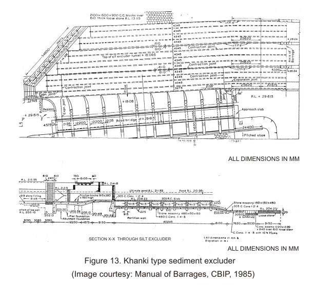
18 hydrograph characteristics of river as well as cut-off available and pond level to be maintained. Generally, gravels and boulders are excluded by keeping the crest of spillway bays low and suspended load and bed load is removed through special silt excluding structures. The structure that is constructed in the undersluice portion of the barrages extending into the river pocket adjacent to the canal head regulator to minimize sediment entry into the a canal head regulator is done with the help of the divide wall which creates a relatively a quite zone (referred to as pocket) in front of the canal intake. The wall divides the stream flow as it approaches the barrages so that part of the flow is diverted to the spillways and part through the undersluice bays. The pocket acts like a ponding area of low velocity which allows much of the sediment to get deposited and flow downstream instead of getting into the canal. The sediment which gets deposited is taken downstream through the sediment excluders which are nothing but a series of tunnels made of reinforced concrete at the river bed level laid in front of the head regulator and ending at the undersluice bays. There are, generally, two common types of layout for sediment excluders. The first type has the mouths of the tunnels that are laid staggered (Figure 13), and is sometimes called the Khanki-type, the name of which is derived from one of the projects where it has been used. The other type of excluder has all the tunnel mouths aligned at an angle in plan (Figure 14), which is called the Trimmu-type excluder.
19
20 A typical cross section of the excluder tunnels is shown in Figure 15, where the canal head regulator has been shown in longitudinal section, since it is at right angles to the excluder tunnels.
21 Though both the staggered-entry and inclined-entry types of excluders have been used, there exist a few differences between them which may be considered while proposing a particular type. The following list enumerates the major comparative merits between the two. The tunnel mouths of the Khanki type being staggered may be extended to any length, each being independent of the other. The positions can be fixed to suit the approach conditions of the river. Hence, this type of excluder possesses a greater flexibility in tunnel arrangement compared to the Kalabagh type. The Khanki type of excluders is more sensitive to changes in river approach conditions and their performance may deteriorate if the river conditions keep changing with time. This is not the case with the Kalabagh type of excluders. The Khanki type of excluders is more complicated to construct as compared to the Kalabagh type. Diversion structures constructed in mountainous regions may have large sized boulders rolling down the river and to remove them away from the head regulator, a structure in the form of a sediment excluder without the top slab has to be provided, which is called a Sediment Deflector as shown in Figure 16.
22 The crest level of head regulators should be higher than the top of the deflector by at least 0.5m to 1m so as to prevent the entry of coarse silt into the head regulator. For the design of the sediment excluders, the following parameters have to be decided: Number of undersluice bays of the barrage that have to be provided with sediment excluder tunnels Number of tunnels that are to be given for each bay of undersluice Location of the mouths of the tunnels The velocity and discharge that may have to be permitted through the tunnels. Interested readers may refer Bureau of Indian Standards Code IS: Design of sediment excluders - guidelines for finalizing the tentative values of the parameters mentioned above apart from the layout, shape, longitudinal section and cross section of the tunnels. The final shape has to be decided from an appropriate model study.
23 4.3.3 Operation and regulation rules for barrages A barrage is such a structure that has gates for controlling flow across almost the whole river section with their crest levels being very close to the riverbed. Hence operation of any gate or groups of gates not only affects the flow pattern in the upstream, that is, in the pool and in the downstream but also the river bed level changes associated with the changes in flow velocity. Further the undersluice bays have to be operated in such a way that there is not significant entry of silt into the off-taking canal. In order to prevent any unnatural flow behaviour and river morphological changes while satisfying the requirements of maintaining the pond level and prevention of sediment entry into the canal, a set of general guidelines have been formulated. Some of the important ones amongst these have been enumerated below: 1. The required pond level is to be maintained both during the non-monsoon flows and the falling flood periods. 2. The non-monsoon flows remain as far as possible near the undersluice bays so that feeding of the canal through a head regulator is not affected. In order to achieve this, therefore, most of the spillway bays are kept shut or opened very marginally. It is only the undersluice bays that operate and pass most of the river discharge which, in turn, creates a deep channel in the riverbed towards the bank where the canal is off-taking. 3. Though it is essential to draw water towards the canal head regulator side by operating the undersluices, it is also to be seen that a fairly uniform distribution of discharge takes place along the width of the barrage, as far as possible. 4. The gate operations should be such that the risk of deep scours or shoal formations (that is, deposition of sediments to form mounds) in the vicinity of the barrage both on the upstream and downstream is minimized, as far as possible. In order to achieve this, it is essential that the gate openings of adjacent bays should not be abruptly different. 5. A gate opening sequence has to be evolved such that deposition of silt and debris is avoided as far as possible on the upstream pool. 6. On the downstream of the barrage structure, the hydraulic jump should not be allowed to form beyond the toe of the downstream glacis. 7. A relatively high intensity of flow is to be avoided in the regions of deep scour, if any has been formed. 8. If a shoal has formed on either upstream or downstream it has to be washed out by an appropriate gate opening sequence. 9. The gate operation schedule should also consider the safe rate of lowering or rising of the pond level.
24 10. Constant and regular supply of water into an off-taking canal has to be ensured even though the discharge coming into the barrage pool may fluctuate as by the outflowing discharges of a power house located on the upstream side. The operation and regulation of barrage gates can be divided into three distinct periods, as mentioned below: 1. Before monsoon (pre-monsoon) 2. During monsoon 3. After monsoon (post-monsoon) The general gate operation strategies for these three periods are given below: Pre-monsoon operation This is a low flow period and wastage of water has to be avoided during this time, as far as possible. The barrage gates shall have to be regulated such that all the available supplies are conserved and pond level is maintained. Any excess flow over and above the requirements through the head regulators have to be released through the undersluice bays and silt excluder tunnels, wherever provided. The releases through the head regulator of the canal have to be based on the accepted discharge formula. For ready reckoning they are usually converted to discharge tables. These tables have to be occasionally checked for accuracy by taking actual measurement of flows in the canal. For any flashy flood, the canal may have to be closed temporarily, if the concentration of suspended sediment is in excess of the safe prescribed limits. Monsoon operation Gauges to indicate flood stage have to be installed sufficiently upstream (about a kilometer or more) of the barrage at suitable location so as to ensure adequate margin of time for operation of gates at the barrage site. During low floods, the gauges have to be signalled and recorded at every three hours while in medium and high floods, these shall be recorded every hour. The signaller at the head works, on receiving the flood warning shall communicate to the official of the headworks and other regulation points downstream. All these can be smoothly achieved if a wireless or telephone connection is established between the gauge reading point and the canal head works at barrage site. The water levels may also be the automatic floating type whose signal can be electrically transmitted to the barrage regulation point. In order to create most favourable conditions for sediment exclusion from the canal, Still-Pond regulation have to be adopted, as explained below. However, in locations where the canals cannot be closed for silt removal, semi-still-pond regulation have to be adopted. These two modes of operation are explained below. Still pond operation In still pond operation, all the gates of the undersluice bays have to be kept closed so as to limit the discharge flowing into the pocket to be equal to the canal withdrawal. The specified or required discharge only should be drawn into the canal and the surplus river
25 discharge should be passed through the spillway bays or river sluice bays, if provided. As the undersluice bays are kept closed, the low velocity in the pocket causes the sediment to settle down and relatively clear water enters the canal. However, the pocket gets silted up in this process after sometime. At, that time, the canal head regulator gates should be closed and the deposited silt should be flushed out by opening the gates of the undersluice bays. The canal supply may be stopped during this scouring operation which may take about 24 hours. After the deposited silt has been flushed out sufficiently, the head regulator gates should be opened and undersluices closed. This operation is desirable where the crest of the head regulator is at a sufficiently higher level than that of the upstream floor of the undersluice bays. This still pond operation should be continued till the river stage reaches the pond level after which the undersluice gates should be opened to avoid overtopping. Semi-still-pond operation In the semi-still-pond operation, the gates of the canal head regulator are not closed for flushing of the silt deposited in the pocket. The gates of the undersluice bays should be kept partially open to the minimum necessary so that the bed material in the pocket could be passed downstream. The discharge in excess of the canal requirement should be passed through the undersluice bays and silt excluder tunnels, wherever provided. During the monsoon months, it is important to keep a constant watch over the sediment entering the head regulator, a portion of which may have to be discarded through a sediment-extractor, if any, provided within the canal. Further, it may have to be ensured that sediment deposition takes place only to the extent that can be washed out early in the cold weather before the full demand develops. For these conditions to satisfy, the following actions may be necessary: 1. Sediment charge observations for both suspended sediment and bed load have to be made at least once a day in low floods immediately below the head regulator, below the silt ejector, if any, and at any other sensitive point lower down the canal. The frequency of observations may have to be increased in medium and high floods as required. 2. The cross section of the canal shall have to be taken at a few critical points to keep a watch on the extent of sediment deposition in the canal. 3. Water surface slopes at the critical points in the head reaches of the canals have to be kept under observation with the help of gauge observations of water levels. 4. The ponding upstream of power stations, for the case of power channels, shall have to be restricted to the requisite extent so as to avoid harmful sediment deposition. 5. The canal may have to be closed from the head under the following situations: Beyond a specified sediment charge during medium or high flood and re-opened when the sediment charge drops down below the specified limit. Since the silt
26 carrying capacity of the canal would govern the specified limit, it would vary from project to project and should be estimated based on actual data or experience of the engineer. When sediment deposition at the critical points has reached the maximum permissible bed level. This limit along with the sediment charge in excess of which the canal is to be kept closed, may have to be fixed for different months during the monsoon period in order to be able to meet the irrigation or power demands. Since cross flows and vertex formations dangerously cause deep scours both on the upstream and downstream of the barrage leading to washing away or sinking of cement concrete blocks and loose stone aprons, and damage to the nose and shanks of guide bunds, visual observations of the direction of current and vortex formation during low and medium floods should be made. After critically observing the effects of different patterns of gate operation on the formation of vortices, the engineer-in-charge would have to judiciously select the correct pattern which cause only minimum scour and minimum shoal formation. The engineer-in-charge shall also have to monitor the shoal formations, changing network of spill channels, etc., which cause unequal distribution of flows through different bays, cross flow near the barrage floor ends, etc. The shoal formations quite close to the barrage may be washed out by judicious gate operation strategies. The pond level has to be kept at the minimum required to feed the canal with the required discharge by suitably operating the gates. If a higher pond is maintained, then the extent of shoal formation would increase. Post-monsoon operation The sediment concentration observations and cross section of the critical points on the canal have to be continued but at less frequent intervals till satisfactory conditions have been established. Still or semi-still pond operation, with sediment excluders or sediment extractions, depending on the surplus water available, have to be continued till the water becomes reasonably clear. When a canal is first opened, a low supply have to run for a few hours at least and the depth should gradually be raised according to the requirements. The rate of filling and lowering of the canal should be prescribed and these should not be transgressed. If a study of the survey data indicates that shoal formation has occurred on the upstream and/or on the downstream of the barrage in spite of a judicial operation of gates, during normal and flushing operation of the pool, the shoal have to be removed by dredging to the extent possible so that satisfactory flow conditions are established and also the desired capacity is restored. Satellite imageries may be studied to detect significant changes of the bank-lines for over the past years and remedial measures taken to improve the river behaviour.
FORMAT FOR SENDING COMMENTS. Title: CRITERIA FOR DESIGN OF CANAL HEAD REGULATORS (Second revision of IS 6531)
") FORMAT FOR SENDING COMMENTS Last Date for Comment is 0 November 009 E-Mail ID for sending comments: rrdash@bis.org.in Document No.: Doc WRD 14 (495)C Title: CRITERIA FOR DESIGN OF CANAL HEAD REGULATORS
FORMAT FOR SENDING COMMENTS Last Date for Comment is 0 November 009 E-Mail ID for sending comments: rrdash@bis.org.in Document No.: Doc WRD 14 (495)C Title: CRITERIA FOR DESIGN OF CANAL HEAD REGULATORS
Components of a Barrage
 Components of a Barrage Definition The only difference between a weir and a barrage is of gates, that is the flow in barrage is regulated by gates and that in weirs, by its crest height. Barrages are costlier
Exercise (4): Open Channel Flow - Gradually Varied Flow
: Open Channel Flow - Gradually Varied Flow") Exercise (4): Open Channel Flow - Gradually Varied Flow 1) A wide channel consists of three long reaches and has two gates located midway of the first and last reaches. The bed slopes for the three reaches
Exercise (4): Open Channel Flow - Gradually Varied Flow 1) A wide channel consists of three long reaches and has two gates located midway of the first and last reaches. The bed slopes for the three reaches
Advanced Hydraulics Prof. Dr. Suresh A. Kartha Department of Civil Engineering Indian Institute of Technology, Guwahati
 Advanced Hydraulics Prof. Dr. Suresh A. Kartha Department of Civil Engineering Indian Institute of Technology, Guwahati Module - 4 Hydraulic Jumps Lecture - 1 Rapidly Varied Flow- Introduction Welcome
JAP Additional Information Sheet
 JAP Additional Information Sheet Block 15: Purpose and Need The USACE purpose of the project is to provide a safe and reliable whitewater park for the recreational public in a city park, which will provide
DAIVÕES DAM SPILLWAY: A NOVEL SOLUTION FOR THE STILLING BASIN
 DAIVÕES DAM SPILLWAY: A NOVEL SOLUTION FOR THE STILLING BASIN Elsa Alves *, Felix Hernando and Rafael Chacón * Laboratório Nacional de Engenharia Civil (LNEC) Av. do Brasil, 101, 1700-066 Lisboa, Portugal
MANERI DAM D/S VIEW. Er. SANDEEP SINGHAL Director (Projects) UJVN Limited, Dehradun, (UK)
 UJVN Limited, Dehradun, (UK)") COMPREHENSIVE REHABILITATION / REPAIR OF MANERI DAM IN DIST. UTTARKASHI MANERI DAM D/S VIEW Er. SANDEEP SINGHAL Director (Projects) UJVN Limited, Dehradun, (UK) sandysinghal14@hotmail.com ABSTRACT Severe
COMPREHENSIVE REHABILITATION / REPAIR OF MANERI DAM IN DIST. UTTARKASHI MANERI DAM D/S VIEW Er. SANDEEP SINGHAL Director (Projects) UJVN Limited, Dehradun, (UK) sandysinghal14@hotmail.com ABSTRACT Severe
Broadly speaking, there are four different types of structures, each with its own particular function:
 3 The selection of structures 3.1 Introduction In selecting a suitable structure to measure or regulate the flow rate in open channels, all demands that will be made upon the structure should be listed.
EXAMPLES (OPEN-CHANNEL FLOW) AUTUMN 2018
 AUTUMN 2018") EXAMPLES (OPEN-CHANNEL FLOW) AUTUMN 2018 Normal and Critical Depths Q1. If the discharge in a channel of width 5 m is 20 m 3 s 1 and Manning s n is 0.02 m 1/3 s, find: (a) the normal depth and Froude number
EXAMPLES (OPEN-CHANNEL FLOW) AUTUMN 2018 Normal and Critical Depths Q1. If the discharge in a channel of width 5 m is 20 m 3 s 1 and Manning s n is 0.02 m 1/3 s, find: (a) the normal depth and Froude number
Exercise (3): Open Channel Flow Rapidly Varied Flow
: Open Channel Flow Rapidly Varied Flow") Exercise (3): Open Channel Flow Rapidly Varied Flow 1) A hydraulic jump exists in a trapezoidal channel having a bed width of 7 m and side slope of 1:1. The flowing discharge is 25 m 3 /sec. Construct
Exercise (3): Open Channel Flow Rapidly Varied Flow 1) A hydraulic jump exists in a trapezoidal channel having a bed width of 7 m and side slope of 1:1. The flowing discharge is 25 m 3 /sec. Construct
APPENDIX C VEGETATED EMERGENCY SPILLWAY. VERSION 1.0 March 1, 2011
 APPENDIX C VEGETATED EMERGENCY SPILLWAY VERSION 1.0 March 1, 2011 [NOTE: Could use a better photo more clearly showing the emergency spillway in the context of the dam.] SECTION C-1: DESCRIPTION OF PRACTICE
DESIGN OF BELL-MOUTH SPILLWAY AT BARVI DAM
 DESIGN OF BELL-MOUTH SPILLWAY AT BARVI DAM Akshay Haldankar 1, Mahesh Bhadra 2, Rahul Harad 3, Darpan Kapre 4, Dipali Patil 5 1,2,3,4 Under graduate,dept. of Civil Engineering, DRIEMS Neral. 5Assistant
(Revised February,2005) CULVERTS, BRIDGES, AND FORDS
 CULVERTS, BRIDGES, AND FORDS") GUIDE TO STREAM CROSSINGS (Revised February,2005) CULVERTS, BRIDGES, AND FORDS Culverts, bridges, and fords are all methods used to cross-streams. Culverts are the most common stream crossing structure.
GUIDE TO STREAM CROSSINGS (Revised February,2005) CULVERTS, BRIDGES, AND FORDS Culverts, bridges, and fords are all methods used to cross-streams. Culverts are the most common stream crossing structure.
APPENDIX B HYDRAULIC DESIGN DATA FOR CULVERTS
 TM 5-820-4/AFM 88-5, Chap 4 APPENDIX B HYDRAULIC DESIGN DATA FOR CULVERTS B-1. General. a. This appendix presents diagrams, charts, coefficients and related information useful in design of culverts. The
Lecture 10 : Sewer Appurtenances
 1 P age Module 8 : Sewer Appurtenances Lecture 10 : Sewer Appurtenances 2 P age The structures, which are constructed at suitable intervals along the sewerage system to help its efficient operation and
STRUCTURE S-65 PURPOSE SPILLWAY OPERATION
 STRUCTURE S-65 This structure is a reinforced concrete, gated spillway with discharge controlled by three cable operated, vertical lift gates, and a reinforced concrete lock structure with two pairs of
Advanced Hydraulics Prof. Dr. Suresh A. Kartha Department of Civil Engineering Indian Institute of Technology, Guwahati
 Advanced Hydraulics Prof. Dr. Suresh A. Kartha Department of Civil Engineering Indian Institute of Technology, Guwahati Module - 4 Hydraulics Jumps Lecture - 4 Features of Hydraulic Jumps (Refer Slide
OFFICE OF STRUCTURES MANUAL FOR HYDROLOGIC AND HYDRAULIC DESIGN CHAPTER 11 APPENDIX B TIDEROUT 2 USERS MANUAL
 OFFICE OF STRUCTURES MANUAL FOR HYDROLOGIC AND HYDRAULIC DESIGN CHAPTER 11 APPENDIX B TIDEROUT 2 USERS MANUAL APRIL 2011 APRIL 2011 Page 1 Preface TIDEROUT 2, Build 1.22 dated June 29, 2006 is the current
Low Gradient Velocity Control Short Term Steep Gradient Channel Lining Medium-Long Term Outlet Control Soil Treatment Permanent [1]
![Low Gradient Velocity Control Short Term Steep Gradient Channel Lining Medium-Long Term Outlet Control Soil Treatment Permanent [1]](/thumbs/80/80811988.jpg "Low Gradient Velocity Control Short Term Steep Gradient Channel Lining Medium-Long Term Outlet Control Soil Treatment Permanent [1]") Check Dams DRAINAGE CONTROL TECHNIQUE Low Gradient Velocity Control Short Term Steep Gradient Channel Lining Medium-Long Term Outlet Control Soil Treatment Permanent [1] [1] Though not generally considered
Check Dams DRAINAGE CONTROL TECHNIQUE Low Gradient Velocity Control Short Term Steep Gradient Channel Lining Medium-Long Term Outlet Control Soil Treatment Permanent [1] [1] Though not generally considered
ANSWERS TO QUESTIONS IN THE NOTES AUTUMN 2018
 ANSWERS TO QUESTIONS IN THE NOTES AUTUMN 2018 Section 1.2 Example. The discharge in a channel with bottom width 3 m is 12 m 3 s 1. If Manning s n is 0.013 m -1/3 s and the streamwise slope is 1 in 200,
Annex E Bridge Pier Protection Plan
 Annex E Bridge Pier Protection Plan Table E1 Bridge Types and Locations Table E2 Flow Conditions For River Sections Figure E1 Bridge Abutment Protection Figure E2 Bridge Pier Protection Figure E3 Central
Rock Ramp Design Guidelines. David Mooney MS Chris Holmquist-Johnson MS Drew Baird Ph.D. P.E. Kent Collins P.E.
 Rock Ramp Design Guidelines David Mooney MS Chris Holmquist-Johnson MS Drew Baird Ph.D. P.E. Kent Collins P.E. Rock Ramp Design Guidelines OUTLINE Local and System Interactions with Rock Ramps Ramp Geometry
APPENDIX A STRUCTURE DESCRIPTIONS AND RATING CURVES
 3 4 5 6 7 8 9 0 3 APPENDIX A STRUCTURE DESCRIPTIONS AND RATING CURVES Kissimmee River Vol December 005 Version Draft 4 3 4 5 6 7 8 9 0 3 4 5 6 7 8 9 0 3 4 5 6 7 8 9 30 3 3 33 34 35 36 37 38 39 40 4 4 43
Culvert Design for Low and High Gradient Streams in the Midwest. Dale Higgins, Hydrologist Chequamegon-Nicolet National Forest
 Culvert Design for Low and High Gradient Streams in the Midwest Dale Higgins, Hydrologist Chequamegon-Nicolet National Forest Overview Culvert Design Considerations Hydraulic Terms Culvert Impacts Low
Experiment (13): Flow channel
: Flow channel") Experiment (13): Flow channel Introduction: An open channel is a duct in which the liquid flows with a free surface exposed to atmospheric pressure. Along the length of the duct, the pressure at the surface
Experiment (13): Flow channel Introduction: An open channel is a duct in which the liquid flows with a free surface exposed to atmospheric pressure. Along the length of the duct, the pressure at the surface
HYDRAULIC JUMP AND WEIR FLOW
 HYDRAULIC JUMP AND WEIR FLOW 1 Condition for formation of hydraulic jump When depth of flow is forced to change from a supercritical depth to a subcritical depth Or Froude number decreases from greater
2O-2 Open Channel Flow
 Iowa Stormwater Management Manual O- O- Open Channel Flow A. Introduction The beginning of any channel design or modification is to understand the hydraulics of the stream. The procedures for performing
TECHNICAL MEMORANDUM 002 EMORANNO. 001
 TECHNICAL MEMORANDUM 002 EMORANNO. 001 To: Jack Synder, P.E. EES Consulting From: Mort McMillen, P.E. Paul Larson, SE Date: October 13, 2010 Project: Cc: Taylor Bowen Subject: Technical Memorandum (TM)
Construction Dewatering
 Construction Dewatering Introduction The control of groundwater is one of the most common and complicated problems encountered on a construction site. Construction dewatering can become a costly issue
General Information for Culvert Design
 Design Manual Chapter 2 - Stormwater 2E - Culvert Design 2E-1 General Information for Culvert Design A. Introduction A culvert is a conduit under an embankment that transports stormwater from one side
Hydraulic Evaluation of the Flow over Polyhedral Morning Glory Spillways
 World Applied Sciences Journal 9 (7): 712-717, 2010 ISSN 1818-4952 IDOSI Publications, 2010 Hydraulic Evaluation of the Flow over Polyhedral Morning Glory Spillways 1 2 2 A. Bagheri, M. Shafai Bajestan,
Ermenek Dam and HEPP: Spillway Test & 3D Numeric-Hydraulic Analysis of Jet Collision
 Ermenek Dam and HEPP: Spillway Test & 3D Numeric-Hydraulic Analysis of Jet Collision J.Linortner & R.Faber Pöyry Energy GmbH, Turkey-Austria E.Üzücek & T.Dinçergök General Directorate of State Hydraulic
Geometric designs for Safe Highways. Dr. Manoj M. Asst. Professor Department of Civil Engineering IIT Delhi
 Geometric designs for Safe Highways Dr. Manoj M. Asst. Professor Department of Civil Engineering IIT Delhi WORKSHOP-CUM-TRAINING PROGRAMME ON ROAD SAFETY 17th 21st September 2018 Outline Introduction Cross
Effect of Fluid Density and Temperature on Discharge Coefficient of Ogee Spillways Using Physical Models
 RESEARCH ARTICLE Effect of Fluid Density and Temperature on Discharge Coefficient of Ogee Spillways Using Physical Models M. SREENIVASULU REDDY 1 DR Y. RAMALINGA REDDY 2 Assistant Professor, School of
Summary of HEC 18, Evaluating Scour at Bridges FHWA NHI Should really follow HEC 18, but this summary will get you the main points.
 Summary of HEC 18, Evaluating Scour at Bridges FHWA NHI 01-001 Should really follow HEC 18, but this summary will get you the main points. 1: Determine scour analysis variables 2: Analyze long-term bed
Chutes Part 2: Synthetic linings
 s Part 2: Synthetic linings DRAINAGE CONTROL TECHNIQUE Low Gradient Velocity Control Short Term Steep Gradient Channel Lining Medium-Long Term Outlet Control [1] Soil Treatment Permanent [2] [1] s can
Course Teacher: Prof. Dr. M. R. Kabir SPILLWAY & IRRIGATION PUMPS. Spillway:
 Spillway: CHAPTER 10 The spillways are openings provided at the body of the dam to discharge safely the excess water or flood water when the water level rises above the normal pool level. Necessity of
APPENDIX J HYDROLOGY AND WATER QUALITY
 APPENDIX J HYDROLOGY AND WATER QUALITY J-1 Technical Report on Airport Drainage, Northern Sector Airport and Ordinance Creek Watershed / Preliminary Creek Constructed Natural Channel Culvert J-2 Preliminary
DEAD-ENDCHANNELFLUSHINGINHARBORS
 DEAD-ENDCHANNELFLUSHNGNHARBORS PURPOSE: The purpose of this technical note is to present some design con- siderations which benefit dead-end channel flushing. Some of these factors can also be used to
Sediment Basin 7E-12. Design Manual Chapter 7 - Erosion and Sediment Control 7E - Design Information for ESC Measures BENEFITS.
 7E-12 Design Manual Chapter 7 - Erosion and Sediment Control 7E - Design Information for ESC Measures Sediment Basin BENEFITS Flow Control Erosion Control Sediment Control Runoff Reduction Flow Diversion
HISTORY OF CONSTRUCTION
 HISTORY OF CONSTRUCTION CFR 257.73(c)(1) West Boiler Slag Pond Clifty Creek Plant Madison, Indiana October, 2016 Prepared for: Indiana Kentucky Electric Corporation Prepared by: American Electric Power
Greenup Lock Filling and Emptying System Study
 Fourth LACCEI International Latin American and Caribbean Conference for Engineering and Technology (LACCET 2006) Breaking Frontiers and Barriers in Engineering: Education, Research and Practice 21-23 June
Suitable Applications Check dams may be appropriate in the following situations: To promote sedimentation behind the dam.
 Categories EC Erosion Control SE Sediment Control TC Tracking Control WE Wind Erosion Control Non-Stormwater NS Management Control Waste Management and WM Materials Pollution Control Legend: Primary Category
Request Number IR1-12: Flow Passage. Information Request
 Request Number IR1-12: Flow Passage Information Request Provide additional information about the 100 metre flow passage channel scenario between the Westshore Terminals and the proposed Project terminal
Proposed Sand/ Moram Mining Project at Gata No.- 17/1 Village- Sehjana, Tehsil & District- Hamirpur, U.P. RISK ASSESMENT RISK ASSESSMENT
 RISK ASSESSMENT Mining and allied activities are associated with several potential hazards to both the employees and the public at large. A worker in a mine should be able to work under conditions, which
CLAIBORNE LOCK AND DAM PERTINENT DATA
 CLAIBORNE LOCK AND DAM PERTINENT DATA GENERAL Location Clarke, Monroe, & Wilcox Counties, Alabama; Alabama River, river mile 72.5 Drainage area Millers Ferry to Claiborne sq. mi. 836 Total drainage area
3. GRADUALLY-VARIED FLOW (GVF) AUTUMN 2018
 AUTUMN 2018") 3. GRADUALLY-VARIED FLOW (GVF) AUTUMN 2018 3.1 Normal Flow vs Gradually-Varied Flow V 2 /2g EGL (energy grade line) Friction slope S f h Geometric slope S 0 In flow the downslope component of weight balances
3. GRADUALLY-VARIED FLOW (GVF) AUTUMN 2018 3.1 Normal Flow vs Gradually-Varied Flow V 2 /2g EGL (energy grade line) Friction slope S f h Geometric slope S 0 In flow the downslope component of weight balances
IMPACT OF MAKING THE CREST OF WEIR MULTIFACETED ON DISCHARGE COEFFICIENT OF MORNING GLORY SPILLWAY
 IMPACT OF MAKING THE CREST OF WEIR MULTIFACETED ON DISCHARGE COEFFICIENT OF MORNING GLORY SPILLWAY Ali Bagheri 1 and *Ebrahim Nohani 2 1 Department of Water Engineering, Qaemshahr Branch, Islamic Azad
Huntington District. For More Information Contact (304)
") Zoar Levee & Diversion Dam are located in the Muskingum River Basin highlighted in green to left. The Muskingum River Basin is the site of Ohio s first multiple purpose water management and land conservation
Zoar Levee & Diversion Dam are located in the Muskingum River Basin highlighted in green to left. The Muskingum River Basin is the site of Ohio s first multiple purpose water management and land conservation
MEMORANDUM. TNC Fisher Slough Final Design and Permitting Subject: DRAFT Technical Memorandum: Levee Emergency Spillway Design
 MEMORANUM TNC Fisher Slough Final esign and Permitting Subject: RAFT Technical Memorandum: Levee Emergency Spillway esign To: From: Internal Memorandum For Record Yen Hsu Chen (Tetra Tech) avid Cline (Tetra
Mr. Michael Malone CPS Energy 145 Navarro Street, Mail Drop San Antonio, Texas Project No
 October 17, 2016 Mr. Michael Malone CPS Energy 145 Navarro Street, Mail Drop 100406 San Antonio, Texas 78296 Project No. 0352436 Subject: Compilation of Construction History Calaveras Power Station San
Dredging Keeping Our Underwater Highways Open
 Dredging Keeping Our Underwater Highways Open Sedimentation Material that falls to the bottom of a liquid is called sediment. If enough sediment deposits to build a shallow spot on the river or ocean bottom,
HY-8 Version 7.2 Build Date January 17, Federal Highway Administration.
 HY-8 Version 7.2 Build Date January 17, 2012 Federal Highway Administration http://www.fhwa.dot.gov/engineering/hydraulics/software/hy8/index.cfm SIMPLE Simple to use Use for simple culverts and bridges
Hydraulic Structures. The late A R Thomas OBE, BSc(Eng), CEng, FICE, FASCE Formerly consultant, Binnie and Partners
, CEng, FICE, FASCE Formerly consultant, Binnie and Partners") 22 Hydraulic Structures The late A R Thomas OBE, BSc(Eng), CEng, FICE, FASCE Formerly consultant, Binnie and Partners Peter Ackers MSc(Eng), CEng, FICE, MIWEM, MASCE Hydraulics consultant Contents 22.1
22 Hydraulic Structures The late A R Thomas OBE, BSc(Eng), CEng, FICE, FASCE Formerly consultant, Binnie and Partners Peter Ackers MSc(Eng), CEng, FICE, MIWEM, MASCE Hydraulics consultant Contents 22.1
STRUCTURAL STABILITY ASSESSMENT
 STRUCTURAL STABILITY ASSESSMENT CFR 257.73(d) Fly Ash Reservoir II Cardinal Plant Brilliant, Ohio October, 2016 Prepared for: Cardinal Operating Company Cardinal Plant Brilliant, Ohio Prepared by: Geotechnical
2. RAPIDLY-VARIED FLOW (RVF) AUTUMN 2018
 AUTUMN 2018") 2. RAPIDLY-VARIED FLOW (RVF) AUTUMN 2018 Rapidly-varied flow is a significant change in water depth over a short distance (a few times water depth). It occurs where there is a local disturbance to the
2. RAPIDLY-VARIED FLOW (RVF) AUTUMN 2018 Rapidly-varied flow is a significant change in water depth over a short distance (a few times water depth). It occurs where there is a local disturbance to the
Low-crested offshore breakwaters: a functional tool for beach management
 Environmental Problems in Coastal Regions VI 237 Low-crested offshore breakwaters: a functional tool for beach management K. Spyropoulos & E. Andrianis TRITON Consulting Engineers, Greece Abstract Beach
Five Counties Salmonid Conservation Program - Fish Passage Design Workshop. February 2013
 Program - Aquatic Organisms and Stream Crossings Ecological Connectivity A watershed is a network of channels that drain a common boundary. Channel characteristics formed by interaction of precipitation,
APPENDIX A STRUCTURE DESCRIPTIONS AND RATING CURVES. Lake Okeechobee & EAA Vol 3 A-i December 2005 Version 1 Draft 4
 1 1 1 1 1 1 1 1 0 1 0 1 0 APPENDIX A STRUCTURE DESCRIPTIONS AND RATING CURVES Lake Okeechobee & EAA Vol A-i December 00 1 1 1 1 1 1 1 1 0 1 from the drainage area served, under a design head of. feet pool
PRELIMINARY RISK ASSESSMENT RIDM PROJECT FOR A DAM WITH A VEGETATION- LINED SPILLWAY AND FERC PILOT
 PRELIMINARY RISK ASSESSMENT FOR A DAM WITH A VEGETATION- LINED SPILLWAY AND FERC PILOT RIDM PROJECT MAY 3, 2018 DAVID S. BOWLES AND LOREN R. ANDERSON RAC ENGINEERS AND ECONOMISTS, LLC AND UTAH STATE UNIVERSITY
The Challenge of Wave Scouring Design for the Confederation Bridge
 13: Coastal and Ocean Engineering ENGI.8751 Undergraduate Student Forum Faculty of Engineering and Applied Science, Memorial University, St. John s, NL, Canada MARCH 2013 Paper Code. (13 - walsh) The Challenge
Earthen Embankments. turning into larger, more costly repairs. The following. The State Dam Safety Program has inspection
 TOPIC: COMMON PROBLEMS FOR SMALL DAMS WITH CONCRETE CHANNEL SPILLWAYS The State Dam Safety Program has inspection requirements for state regulated dams. A dam, like any man-made structure, will change
6.6 Gradually Varied Flow
 6.6 Gradually Varied Flow Non-uniform flow is a flow for which the depth of flow is varied. This varied flow can be either Gradually varied flow (GVF) or Rapidly varied flow (RVF). uch situations occur
OFFICE OF STRUCTURES MANUAL FOR HYDROLOGIC AND HYDRAULIC DESIGN CHAPTER 13 CULVERTS APRIL 2011
 OFFICE OF STRUCTURES MANUAL FOR HYDROLOGIC AND HYDRAULIC DESIGN CHAPTER 13 CULVERTS APRIL 2011 APRIL 2011 Chapter 13 Culverts Table of Contents Foreword.3 13.1 Introduction.. 4 13.2 Policy 6 13.3 Passage
Plan B Dam Breach Assessment
 Plan B Dam Breach Assessment Introduction In support of the Local Sponsor permit applications to the states of Minnesota and North Dakota, a dam breach analysis for the Plan B alignment of the Fargo-Moorhead
19.1 Problem: Maximum Discharge
 19.1 Problem: Maximum Discharge In partially full channel having an equilateral triangular cross section, the rate of discharge is Q = KAR/3 in which K is a constant, A flow area, R is the hydraulic mean
Khosla's theory. After studying a lot of dam failure constructed based on Bligh s theory, Khosla came out with the following;
 Khosla's theory After studying a lot of dam failure constructed based on Bligh s theory, Khosla came out with the following; Following are some of the main points from Khosla's Theory From observation
As temporary grade control facilities along waterways until final stabilization is established.
 Check Dams (CD) EC-12 Description Check dams are temporary grade control structures placed in drainage channels to limit the erosivity of stormwater by reducing flow velocity. Check dams are typically
COST EFFECTIVE STORAGE CAPACITY INCREASE FOR ALUMINA TAILINGS DISPOSAL AREA THROUGH SPILLWAY OPTIMISATION
 COST EFFECTIVE STORAGE CAPACITY INCREASE FOR ALUMINA TAILINGS DISPOSAL AREA THROUGH SPILLWAY OPTIMISATION Abstract Lonie I * Tailings and Dams, GHD Brisbane, QLD, Australia Queensland Alumina Limited operates
FSOC Upstream Fish Passage Guidance Document
 FSOC Upstream Fish Passage Guidance Document STEP 1: Identify species and life stages in need of fish passage STEP 2: Identify fishway options and species applicability STEP 3 Fish passage criteria review
Evaluation of step s slope on energy dissipation in stepped spillway
 International Journal of Engineering & Technology, 3 (4) (2014) 501-505 Science Publishing Corporation www.sciencepubco.com/index.php/ijet doi: 10.14419/ijet.v3i4.3561 Research Paper Evaluation of step
STRUCTURE 65-B PURPOSE SPILLWAY OPERATION
 STRUCTURE 65-B This structure is a reinforced concrete, gated spillway with discharge controlled by three cable operated vertical lift gates and a reinforced concrete lock structure with two pairs of sector
NUMERICAL AND PHYSICAL MODELING
 POINTE DU BOIS GENERATING STATION SPILLWAY REPLACEMENT PROJECT NUMERICAL AND PHYSICAL MODELING Kara Hurtig, Northwest Hydraulic Consultants, North Vancouver, BC, Canada David S. Brown, KGS Group, Winnipeg,
BC Ministry of Forests. March Fish Stream Crossing Guidebook. Forest Practices Code of British Columbia.
 FRST 557 Lecture 7c Bridges and Culverts: Water Velocity and Discharge Lesson Background and Overview: The previous two lessons presented methods for estimating water volume flow at a particular site and
Highway geometric design QUESTION PAPER
 QUESTION PAPER UNIT 1 1. Explain the design control and criteria which governs the design and highway. ( Dec 2011, june july 2011, June 2010, Dec 2010, Dec 2012) 2.Explain PCU value and factors affecting
NOVEMBER 2006 FLOOD DOWNSTREAM OF THE KATSE DAM STRUCTURE
 THE LESOTHO HIGHLANDS DEVELOPMENT AUTHORITY (LHDA) NOVEMBER 2006 FLOOD DOWNSTREAM OF THE KATSE DAM STRUCTURE Effects of the November 2006 Flood THE DAMAGE CAUSED BY THE FLOOD AS IT PROPAGATES DOWNSTREAM
TYPES OF FOUNDATION. Superstructure. Substructure. Foundation
 TYPES OF FOUNDATION Introduction: The lowest artificially built part of a structure which transmits the load of the structure to the soil lying underneath is called foundation. The supporting part of a
TM /AFM 88-5, Chap Underground hydraulic design Inlets UFC - Drainage In Areas Other Than Airfields
 sults of laboratory research concerning soil infiltration through pipe joints and the effectiveness of gasketing tapes for waterproofing joints and seams are available. 3 6. Underground hydraulic design.
Hydrographic Surveying Methods, Applications and Uses
 Definition: Hydrographic Surveying Methods, Applications and Uses It is the branch of surveying which deals with any body of still or running water such as a lake, harbor, stream or river. Hydrographic
Section 5: Pond Outlets
 Section : Pond Outlets Defining and calculating pond outlet devices 8 Minutes Press Space, PageDown, or Click to advance. Press PageUp to reverse. Esc to exit. Right-Click for other options. Outlets Introduction
CHAPTER 4 SPALDING COUNTY, GEORGIA 4.0 CULVERT DESIGN
 SPALDING COUNTY, GEORGIA CHAPTER 4 4.0 CULVERT DESIGN... 4-1 4.1 INTRODUCTION... 4-1 4.2 SYMBOLS AND DEFINITIONS... 4-1 4.3 ENGINEERING DESIGN CRITERIA... 4-2 4.3.1 FREQUENCY FLOOD... 4-2 4.3.2 VELOCITY
DESIGN OF SCOUR PROTECTION FOR THE BRIDGE PIERS OF THE 0RESUND LINK
 DESIGN OF SCOUR PROTECTION FOR THE BRIDGE PIERS OF THE 0RESUND LINK Lars Kirkegaard 1, Mogens Hebsgaard 2 and Ole Juul Jensen 3 Abstract The 0resund Link between Denmark and Sweden consists of a cable
UNDERWATER BRIDGE INSPECTION REPORT STRUCTURE NO CSAH 4 OVER THE BEAVER RIVER ST. LOUIS COUNTY
 UNDERWATER BRIDGE INSPECTION REPORT STRUCTURE NO. 7635 CSAH 4 OVER THE BEAVER RIVER ST. LOUIS COUNTY JUNE 18, 2012 PREPARED FOR THE MINNESOTA DEPARTMENT OF TRANSPORTATION BY COLLINS ENGINEERS, INC. JOB
Prof. B V S Viswanadham, Department of Civil Engineering, IIT Bombay
 43 Module 3: Lecture - 5 on Compressibility and Consolidation Contents Stresses in soil from surface loads; Terzaghi s 1-D consolidation theory; Application in different boundary conditions; Ramp loading;
ITEM 400 STRUCTURAL EXCAVATION AND BACKFILL
 AFTER MARCH 1, 2012 ITEM 400 STRUCTURAL EXCAVATION AND BACKFILL 400.1 Description. This item shall govern for all excavation required for the construction of all structures, except pipe or box sewers for
Hours / 100 Marks Seat No.
 17421 21415 3 Hours / 100 Marks Seat No. Instructions : (1) All Questions are compulsory. (2) Answer each next main Question on a new page. (3) Illustrate your answers with neat sketches wherever necessary.
MODELLING ANCILLARIES: WEIR COEFFICIENTS
 WaPUG USER NOTE No 27 MODELLING ANCILLARIES: WEIR COEFFICIENTS David Balmforth, MWH 1. SCOPE This user note gives advice on the choice of coefficient for overflo eirs and orifices hen modelling storm seage
Design and Installation of two Permanent Booms at La Romaine-2 to resist Ice, retain Debris and serve as Safety Booms.
 CGU HS Committee on River Ice Processes and the Environment 18 th Workshop on the Hydraulics of Ice Covered Rivers Quebec City, QC, Canada, August 18-20, 2015 Design and Installation of two Permanent Booms
OPEN CHANNEL FLOW WORKSHEET 3 WATER SURFACE PROFILES
 Learning Objectives OPEN CHANNEL FLOW WORKSHEET 3 WATER SURFACE PROFILES 1. Learn about gradually varied flow and rapidly varying flow 2. Discuss different types of water surface profiles 3. Discuss the
CROSS COURSE INSTRUCTION DOCUMENT
 CROSS COURSE INSTRUCTION DOCUMENT Table of Contents CROSS COURSE DESCRIPTION... 3! CRITERIA FOR SBX/SX RUN SELECTION... 4! Gradients / Slope inclinations... 4! Run Width... 4! Level of Courses... 8! Beginner
UNDERWATER BRIDGE INSPECTION REPORT DISTRICT 8 - LAC QUI PARLE COUNTY
 UNDERWATER BRIDGE INSPECTION REPORT STRUCTURE NO. 6391 CSAH NO. 33 OVER THE MINNESOTA RIVER DISTRICT 8 - LAC QUI PARLE COUNTY OCTOBER 22, 2012 PREPARED FOR THE MINNESOTA DEPARTMENT OF TRANSPORTATION BY
Project 184 Preferred Canal Drainage Structure and Release Point Plan
 Project 184 Preferred Canal Drainage Structure and Release Point Plan September 2011 Version 5.0 REVISION HISTORY Page Description Date 7 Added Section 5.1 Plan Modifications 09/08/11 9 Modified Table
Large-scale Field Test
 Vaskinn 1 Large-scale Field Test Kjetil Arne Vaskinn kav@trh.statkraftgroner.no Statkraft Grøner AS SUMMARY The objective the controlled failure of large-scale embankment is to monitor and record the failure
Grit chambers are basin to remove the inorganic particles to prevent damage to the pumps, and to prevent their accumulation in sludge digestors.
 Home Lecture Quiz Design Example Grit Chambers Types of Grit Chambers Aerated Grit Chamber Principle of Working of Grit Chamber Design of Grit Chambers Primary Sedimentation Grit Chambers Grit chambers
Road Markings. Lecture Notes in Transportation Systems Engineering. Prof. Tom V. Mathew
 Road Markings Lecture Notes in Transportation Systems Engineering Prof. Tom V. Mathew 1 Overview The essential purpose of road markings is to guide and control traffic on a highway. They supplement the
OIL SUPPLY SYSTEMS ABOVE 45kW OUTPUT 4.1 Oil Supply
 OIL SUPPLY SYSTEMS ABOVE 45kW OUTPUT 4.1 Oil Supply 4.1.1 General The primary function of a system for handling fuel oil is to transfer oil from the storage tank to the oil burner at specified conditions
USING A LABYRINTH WEIR TO INCREASE HYDRAULIC CAPACITY. Dustin Mortensen, P.E. 1 Jake Eckersley, P.E. 1
 USING A LABYRINTH WEIR TO INCREASE HYDRAULIC CAPACITY Dustin Mortensen, P.E. 1 Jake Eckersley, P.E. 1 Plum Creek Floodwater Retarding Structure No. 6 is located in an area of Kyle, Texas, that is currently
CORPS FACTS. Harbor Dredging U.S. ARMY CORPS OF ENGINEERS BUILDING STRONG
 CORPS FACTS Harbor Dredging U.S. ARMY CORPS OF ENGINEERS BUILDING STRONG Disaster Response Sedimentation in the channel is caused by the normal cycle of silt movement, erosion from high water or heavy
3.6 Magnetic surveys. Sampling Time variations Gradiometers Processing. Sampling
 3.6 Magnetic surveys Sampling Time variations Gradiometers Processing Sampling Magnetic surveys can be taken along profiles or, more often, on a grid. The data for a grid is usually taken with fairly frequent
3-13 UFC - GENERAL PROVISIONS AND GEOMETRIC DESIGN FOR ROADS, STREETS, WALKS, AND OPEN
 maintenance, and erosion. Stability is required to maintain the integrity of the pavement structure, and a slope stability analysis should be conducted for cuts and fills greater than 15 feet. For lower