CHAPTER 4 SPALDING COUNTY, GEORGIA 4.0 CULVERT DESIGN
|
|
|
- Arline Blair
- 5 years ago
- Views:
Transcription
1 SPALDING COUNTY, GEORGIA CHAPTER CULVERT DESIGN INTRODUCTION SYMBOLS AND DEFINITIONS ENGINEERING DESIGN CRITERIA FREQUENCY FLOOD VELOCITY LIMITATIONS BUOYANCY PROTECTION LENGTH AND SLOPE DEBRIS CONTROL HEADWATER LIMITATIONS TAILWATER CONSIDERATIONS STORAGE CULVERT INLETS INLETS WITH HEADWALLS WINGWALLS AND APRONS IMPROVED INLETS MATERIAL SELECTION CULVERT SKEWS CULVERT SIZES OUTLET PROTECTION EROSION AND SEDIMENT CONTROL ENVIRONMENTAL CONSIDERATIONS DESIGN PROCEDURES INLET AND OUTLET CONTROL PROCEDURES NOMOGRAPHS STEPS IN DESIGN PROCEDURE PERFORMANCE CURVES - ROADWAY OVERTOPPING STORAGE ROUTING CULVERT DESIGN EXAMPLE INTRODUCTION EXAMPLE EXAMPLE DATA COMPUTATIONS DESIGN PROCEDURES FOR BEVELED-EDGED INLETS INTRODUCTION DESIGN FIGURES DESIGN PROCEDURE DESIGN FIGURE LIMITS MULTIBARREL INSTALLATIONS SKEWED INLETS FLOOD ROUTING AND CULVERT DESIGN INTRODUCTION i
2 4.7.2 DESIGN PROCEDURE CULVERT DESIGN CHARTS AND NOMOGRAPHS REFERENCES ii
3 4.0 CULVERT DESIGN 4.1 Introduction A culvert is a short, closed (covered) conduit that conveys stormwater runoff under an embankment, usually a roadway. The primary purpose of a culvert is to convey surface water, but properly designed it may also be used to restrict flow and reduce downstream peak flows. In addition to the hydraulic function, a culvert must also support the embankment and/or roadway, and protect traffic and adjacent property owners from flood hazards to the extent practicable. Most culvert design is empirical and relies on nomographs and cookbook procedures. The purpose of this section is to provide an overview of culvert design criteria and procedures. 4.2 Symbols and Definitions To provide consistency within this section as well as throughout this Manual the symbols listed in Table 4-1 will be used. These symbols were selected because of their wide use. Table 4-1 Symbols and Definitions Symbol Definition Units A Area of cross section of flow ft² B Barrel width ft Cd Overtopping discharge coefficient - D Culvert diameter or barrel depth in or ft d Depth of flow ft dc Critical depth of flow ft du Uniform depth of flow ft g Acceleration of gravity ft/s Hf Depth of pool or head, above the face section of invert ft ho Height of hydraulic grade line above outlet invert ft HW Headwater depth above invert of culvert (depth from inlet invert to upstream total energy grade line) ft Ke Inlet loss coefficient - L Length of culvert ft N Number of barrels - Q Rate of discharge cfs S Slope of culvert ft/ft TW Tailwater depth above invert of culvert ft V Mean velocity of flow ft/s Vc Critical velocity ft/s 4-1
4 4.3 Engineering Design Criteria The design of a culvert should take into account many different engineering and technical aspects at the culvert site and adjacent areas. The following design criteria should be considered for all culvert designs as applicable Frequency Flood See Section 3.0 or the local review authority for design storm requirements for the sizing of culverts. The 25-year frequency storm shall be routed through all culverts to be sure building structures (e.g., houses, commercial buildings) are not flooded or increased damage does not occur to the highway or adjacent property for this design event. While the 100, 50- year storms should be considered in design preparation. The minimum pipe size allowable by Spalding County is 18 inches Velocity Limitations Both minimum and maximum velocities should be considered when designing a culvert. The maximum velocity should be consistent with channel stability requirements at the culvert outlet. The maximum allowable velocity for corrugated metal pipe is 15 feet per second. There is no specified maximum allowable velocity for reinforced concrete pipe, but outlet protection shall be provided where discharge velocities will cause erosion problems. To ensure self-cleaning during partial depth flow, a minimum velocity of 2.5 feet per second, for the 2-year flow, when the culvert is flowing partially full is required Buoyancy Protection Headwalls, endwalls, slope paving or other means of anchoring to provide buoyancy protection should be considered for all flexible culverts Length and Slope The culvert length and slope should be chosen to approximate existing topography and, to the degree practicable, the culvert invert should be aligned with the channel bottom and the skew angle of the stream, and the culvert entrance should match the geometry of the roadway embankment. The maximum slope using concrete pipe is 10% and for CMP is 14% before pipe restraining methods must be taken. Maximum drop in a drainage structure is 10 feet Debris Control In designing debris control structures it is recommended that the Hydraulic Engineering Circular No. 9 entitled Debris Control Structures be consulted Headwater Limitations Headwater is water above the culvert invert at the entrance end of the culvert. The allowable headwater elevation is that elevation above which damage may be caused to adjacent property and/or the roadway and is determined from an evaluation of land use 4-2
5 upstream of the culvert and the proposed or existing roadway elevation. It is this allowable headwater depth that is the primary basis for sizing a culvert. The following criteria related to headwater should be considered: The allowable headwater is the depth of water that can be ponded at the upstream end of the culvert during the design flood, which will be limited by one or more of the following constraints or conditions: (1) Headwater be non-damaging to upstream property (2) Ponding depth be no greater than the low point in the road grade (3) Ponding depth be no greater than the elevation where flow diverts around the culvert (4) Elevations established to delineate floodplain zoning (5) 18-inch (or applicable) freeboard requirements The following HW/D criteria: (1) For drainage facilities with cross-sectional area equal to or less than 30 ft², HW/D should be equal to or less than 1.5 (2) For drainage facilities with cross-sectional area greater than 30 ft², HW/D should be equal to or less than 1.2 The headwater should be checked for the 100-year flood to ensure compliance with flood plain management criteria and for most facilities the culvert should be sized to maintain flood-free conditions on major thoroughfares with 18-inch freeboard at the low-point of the road. The maximum acceptable outlet velocity should be identified (see subsection 5.4). Either the headwater should be set to produce acceptable velocities, or stabilization or energy dissipation should be provided where these velocities are exceeded. In general, the constraint that gives the lowest allowable headwater elevation establishes the criteria for the hydraulic calculations. Other site-specific design considerations should be addressed as required Tailwater Considerations The hydraulic conditions downstream of the culvert site must be evaluated to determine a tailwater depth for a range of discharge. At times there may be a need for calculating backwater curves to establish the tailwater conditions. The following conditions must be considered: If the culvert outlet is operating with a free outfall, the critical depth and equivalent hydraulic grade line should be determined. 4-3
6 For culverts that discharge to an open channel, the stage-discharge curve for the channel must be determined. See Section 5.0, Open Channel Design. If an upstream culvert outlet is located near a downstream culvert inlet, the headwater elevation of the downstream culvert may establish the design tailwater depth for the upstream culvert. If the culvert discharges to a lake, pond, or other major water body, the expected high water elevation of the particular water body may establish the culvert tailwater Storage If storage is being assumed or will occur upstream of the culvert, refer to subsection regarding storage routing as part of the culvert design Culvert Inlets Hydraulic efficiency and cost can be significantly affected by inlet conditions. The inlet coefficient Ke, is a measure of the hydraulic efficiency of the inlet, with lower values indicating greater efficiency. Recommended inlet coefficients are given in Table Inlets with Headwalls Headwalls may be used for a variety of reasons, including increasing the efficiency of the inlet, providing embankment stability, providing embankment protection against erosion, providing protection from buoyancy, and shortening the length of the required structure. Headwalls are required for all metal culverts and where buoyancy protection is necessary. If high headwater depths are to be encountered, or the approach velocity in the channel will cause scour, a short channel apron should be provided at the toe of the headwall. This apron should extend at least one pipe diameter upstream from the entrance, and the top of the apron should not protrude above the normal streambed elevation Wingwalls and Aprons Wingwalls are used where the side slopes of the channel adjacent to the entrance are unstable or where the culvert is skewed to the normal channel flow Improved Inlets Where inlet conditions control the amount of flow that can pass through the culvert, improved inlets can greatly increase the hydraulic performance of the culvert Material Selection Reinforced concrete pipe (RCP) is required for use (1) under a roadway, (2) when pipe slopes are less than 1%, or (3) for all flowing streams. RCP and fully coated corrugated metal pipe can be used in all other cases. High-density polyethylene (HDPE) pipe may not be used.. Table 4-3 gives recommended Manning's n values for different materials. 4-4
7 Culvert Skews Culvert skews shall not exceed 45 degrees as measured from a line perpendicular to the roadway centerline without approval Culvert Sizes The minimum allowable pipe diameter shall be 18 inches. 4-5
8 Table 4-2 Inlet Coefficients Type of Structure and Design of Entrance Coefficient Ke Pipe, Concrete Projecting from fill, socket end (grove-end) 0.2 Projecting from fill, square cut end 0.5 Headwall or headwall and wingwalls Socket end of pipe (groove-end) 0.2 Square-edge 0.5 Rounded [radius = 1/12(D)] 0.2 Mitered to conform to fill slope 0.7 *End-Section conforming to fill slope 0.5 Beveled edges, 33.7 or 45 bevels 0.2 Side- or slope-tapered inlet 0.2 Pipe, or Pipe-Arch, Corrugated Metal Projecting from fill (no headwall) 0.9 Headwall or headwall and wingwalls square-edge 0.5 Mitered to fill slope, paved or unpaved slope 0.7 *End-Section conforming to fill slope 0.5 Beveled edges, 33.7 or 45 bevels 0.2 Side- or slope-tapered inlet 0.2 Box, Reinforced Concrete Headwall parallel to embankment (no wingwalls) Square-edged on 3 edges 0.5 Rounded on 3 edges to radius of [1/12(D)] or beveled edges on 3 sides 0.2 Wingwalls at 30 to 75 to barrel Square-edged at crown 0.4 Crown edge rounded to radius of [1/12(D)] or beveled top edge 0.2 Wingwalls at 10 or 25 to barrel Square-edged at crown 0.5 Wingwalls parallel (extension of sides) Square-edged at crown 0.7 Side- or slope-tapered inlet Although laboratory tests have not been completed on Ke values for High-Density Polyethylene (HDPE) pipes, the Ke values for corrugated metal pipes are recommended for HDPE pipes. * Note: End Section conforming to fill slope, made of either metal or concrete, are the sections commonly available from manufacturers. From limited hydraulic tests they are equivalent in operation to a headwall in both inlet and outlet control. Source: HDS No. 5,
9 Table 4-3 Manning's n Values Type of Conduit Wall & Joint Description Manning's n Concrete Pipe Good joints, smooth walls Good joints, rough walls Poor joints, rough walls Concrete Box Good joints, smooth finished walls Poor joints, rough, unfinished walls Corrugated 2 2/3- by ½-inch corrugations Metal Pipes and 6- by 1-inch corrugations Boxes Annular 5- by 1-inch corrugations Corrugations 3- by 1-inch corrugations by 2-inch structural plate by 2-1/2 inch structural plate Corrugated Metal 2 2/3-by ½-inch corrugated Pipes, Helical 24-inch plate width Corrugations, Full Circular Flow Spiral Rib Metal 3/4 by 3/4 in recesses at 12 inch Pipe spacing, good joints High Density Polyethylene (HDPE) Corrugated Smooth Liner Corrugated Polyvinyl Chloride (PVC) Source: HDS No. 5, 1985 Note: For further information concerning Manning n values for selected conduits consult Hydraulic Design of Highway Culverts, Federal Highway Administration, HDS No. 5, page Outlet Protection See Section 4.5 for information on the design of outlet protection. Outlet protection should be provided for the 25-year storm Erosion and Sediment Control Erosion and sediment control shall be in accordance with the latest approved Soil Erosion and Sediment Control Ordinance for the municipality. See also the Manual for Erosion and Sediment Control in Georgia for design standards and details related to erosion and sediment control Environmental Considerations Where compatible with good hydraulic engineering, a site should be selected that will permit the culvert to be constructed to cause the least impact on the stream or wetlands. This selection must consider the entire site, including any necessary lead channels. 4-7
10 4.4 Design Procedures Inlet and Outlet Control There are two types of flow conditions for culverts that are based upon the location of the control section and the critical flow depth: Inlet Control Inlet control occurs when the culvert barrel is capable of conveying more flow that the inlet will accept. This typically happens when a culvert is operating on a steep slope. The control section of a culvert is located just inside the entrance. Critical depth occurs at or near this location, and the flow regime immediately downstream is supercritical. Outlet Control Outlet control flow occurs when the culvert barrel is not capable of conveying as much flow as the inlet opening will accept. The control section for outlet control flow in a culvert is located at the barrel exit or further downstream. Either subcritical or pressure flow exists in the culvert barrel under these conditions. Figure 4-1 Culvert Flow Conditions (Adapted from: HDS-5, 1985) Proper culvert design and analysis requires checking for both inlet and outlet control to determine which will govern particular culvert designs. For more information on inlet and outlet control, see the FHWA Hydraulic Design of Highway Culverts, HDS-5, Procedures There are two procedures for designing culverts: manual use of inlet and outlet control nomographs, and the use computer programs such as HY8. It is recommended that the HY8 computer model or equivalent be used for culvert design. The computer software package HYDRAIN, which includes HY8, uses the theoretical basis from the nomographs to size culverts. In addition, this software can evaluate improved inlets, route hydrographs, consider road overtopping, and evaluate outlet streambed scour. By using water surface profiles, this procedure is more accurate in predicting backwater effects and outlet scour. 4-8
11 4.4.3 Nomographs The use of culvert design nomographs requires a trial and error solution. Nomograph solutions provide reliable designs for many applications. It should be remembered that velocity, hydrograph routing, roadway overtopping, and outlet scour require additional, separate computations beyond what can be obtained from the nomographs. Figures 4-2 and 4-3 show examples of an inlet control and outlet control nomograph for the design of concrete pipe culverts. For other culvert designs, refer to the complete set of nomographs in subsection 4.8. Figure 4-2 Headwater Depth for Concrete Pipe Culvert with Inlet Control 4-9
12 Figure 4-3 Head for Concrete Pipe Culverts Flowing Full Steps In Design Procedure The following design procedure requires the use of inlet and outlet nomographs. (Step 1) (Step 2) (Step 3) List design data: Q = discharge (cfs) L = culvert length (ft) S = culvert slope (ft/ft) TW= tailwater depth (ft) V = velocity for trial diameter (ft/s) Ke= inlet loss coefficient HW= allowable headwater depth for the design storm (ft) Determine trail culvert size by assuming a trial velocity 3 to 5 ft/s and computing the culvert area, A = Q/V. Determine the culvert diameter (inches). Find the actual HW for the trial size culvert for both inlet and outlet control. 4-10
13 For inlet control, enter inlet control nomograph with D and Q and find HW/D for the proper entrance type. Compute HW and, if too large or too small, try another culvert size before computing HW for outlet control. For outlet control enter the outlet control nomograph with the culvert length, entrance loss coefficient, and trial culvert diameter. To compute HW, connect the length scale for the type of entrance condition and culvert diameter scale with a straight line, pivot on the turning line, and draw a straight line from the design discharge through the turning point to the head loss scale H. Compute the headwater elevation HW from the equation: HW = H + ho - LS (4.1) (Step 4) (Step 5) Where: ho = ½ (critical depth + D), or tailwater depth, whichever is greater L = culvert length S = culvert slope Compare the computed headwaters and use the higher HW nomograph to determine if the culvert is under inlet or outlet control. If inlet control governs, then the design is complete and no further analysis is required. If outlet control governs and the HW is unacceptable, select a larger trial size and find another HW with the outlet control nomographs. Since the smaller size of culvert had been selected for allowable HW by the inlet control nomographs, the inlet control for the larger pipe need not be checked. Calculate exit velocity and if erosion problems might be expected, refer to Section 7.0 for appropriate energy dissipation designs Performance Curves - Roadway Overtopping A performance curve for any culvert can be obtained from the nomographs by repeating the steps outlined above for a range of discharges that are of interest for that particular culvert design. A graph is then plotted of headwater versus discharge with sufficient points so that a curve can be drawn through the range of interest. These curves are applicable through a range of headwater, velocities, and scour depths versus discharges for a length and type of culvert. Usually charts with length intervals of 25 to 50 feet are satisfactory for design purposes. Such computations are made much easier by the use of computer programs. To complete the culvert design, roadway overtopping should be analyzed. A performance curve showing the culvert flow as well as the flow across the roadway is a useful analysis tool. Rather than using a trial and error procedure to determine the flow division between the overtopping flow and the culvert flow, an overall performance curve can be developed. 4-11
14 The overall performance curve can be determined as follows: (Step 1) (Step 2) (Step 3) Select a range of flow rates and determine the corresponding headwater elevations for the culvert flow alone. The flow rates should fall above and below the design discharge and cover the entire flow range of interest. Both inlet and outlet control headwaters should be calculated. Combine the inlet and outlet control performance curves to define a single performance curve for the culvert. When the culvert headwater elevations exceed the roadway crest elevation, overtopping will begin. Calculate the equivalent upstream water surface depth above the roadway (crest of weir) for each selected flow rate. Use these water surface depths and equation 4. to calculate flow rates across the roadway. Q = CdL(HW) 1.5 (4.2) Where: Q = overtopping flow rate (ft³/s) Cd = overtopping discharge coefficient L = length of roadway (ft) HW = upstream depth, measured from the roadway crest to the water surface upstream of the weir drawdown (ft) (Step 4) Note: See Figure 4-4 on the next page for guidance in determining a value for Cd. For more information on calculating overtopping flow rates see pages in HDS No. 5. Add the culvert flow and the roadway overtopping flow at the corresponding headwater elevations to obtain the overall culvert performance curve Storage Routing A significant storage capacity behind a highway embankment attenuates a flood hydrograph. Because of the reduction of the peak discharge associated with this attenuation, the required capacity of the culvert, and its size, may be reduced considerably. If significant storage is anticipated behind a culvert, the design should be checked by routing the design hydrographs through the culvert to determine the discharge and stage behind the culvert. See subsection 4.7 and Section 2.2 for more information on routing. Additional routing procedures are outlined in Hydraulic Design of Highway Culverts, Section V - Storage Routing, HDS No. 5, Federal Highway Administration. Note: Storage should be taken into consideration only if the storage area will remain available for the life of the culvert as a result of purchase of ownership or right-of-way or an easement has been acquired. 4-12
15 Figure 4-4 Discharge Coefficients for Roadway Overtopping (Source: HDS No. 5, 1985) 4.5 Culvert Design Example Introduction The following example problem illustrates the procedures to be used in designing culverts using the nomographs Example Size a culvert given the following example data, which were determined by physical limitations at the culvert site and hydraulic procedures described elsewhere in this handbook Example Data Input Data Discharge for 2-yr flood = 40 cfs Discharge for 25-yr flood = 75 cfs Allowable Hw for 25-yr discharge = 5.15 ft Length of culvert = 125 ft Natural channel invert elevations - inlet = ft, outlet = ft Culvert slope = ft/ft Tailwater depth for 25-yr discharge = 3.4 ft 4-13
16 Tailwater depth is the normal depth in downstream channel Entrance type = Groove end with headwall Computations (1) Assume a culvert velocity of 5 ft/s. Required flow area = 75 cfs/5 ft/s = 15 ft² (for the 25-yr recurrence flood). (2) The corresponding culvert diameter is about 48 in. This can be calculated by using the formula for area of a circle: Area = (3.14D²)/4 or D = (Area times 4/3.14) 0.5. Therefore: D = ((15 sq ft x 4)/3.14) 0.5 x 12 in/ft) = 52.5 in (3) A grooved end culvert with a headwall is selected for the design. Using the inlet control nomograph (Figure 4-2), with a pipe diameter of 48 inches and a discharge of 75 cfs; read a HW/D value of (4) The depth of headwater (HW) is (0.96) x (4) = 3.84 ft, which is less than the allowable headwater of 5.15 ft. Since 3.84 ft is considerably less than 5.15 try a smaller culvert. (5) Using the same procedures outlined in Steps 4 and 5 the following results were obtained. 42-inch culvert HW = 4.48 ft 36-inch culvert HW = 6.57 ft Select a 42-inch culvert to check for outlet control. (6) The culvert is checked for outlet control by using Figure 4-3. With an entrance loss coefficient Ke of 0.20, a culvert length of 125 ft, and a pipe diameter of 42 in., an H value of 1.65 ft is determined. The headwater for outlet control is computed by the equation: HW = H + ho - LS Compute ho ho = Tw or ½ (critical depth in culvert + D), whichever is greater. ho = 3.4 ft or ho = ½ ( ) = ft Note: critical depth is obtained from Chart 4 on page 4-22 Therefore: ho = 3.4 ft The headwater depth for outlet control is: HW = H + ho - LS = (100) x (0.012) = ft (7) Since HW for outlet control (3.025 ft) is greater than the HW for inlet control (4.48 ft), inlet control governs the culvert design. Thus, the maximum headwater expected for a 25-year recurrence flood is 4.48 ft, which is less than the allowable headwater of 5.15 ft. (8) Estimate outlet exit velocity. Since this culvert is on outlet control and discharges into an open channel downstream with tailwater above culvert, the culvert will be flowing full at the flow depth in the channel. Using the design peak discharge of 4-14
17 75 cfs and the area of a 42-inch or 3.5-foot diameter culvert the exit velocity will be: Q = VA Therefore: V = 75 / (3.14(3.5)²)/4 = 7.8 ft/s With this high velocity, consideration should be given to provide an energy dissipator at the culvert outlet. See Section 7.0 (Energy Dissipation Design). (9) Check for minimum velocity using the 2-year flow of 40 cfs. Therefore: V = 40 / (3.14(3.5)²/4 =4.16 ft/s > minimum of OK (10) The 100-year flow should be routed through the culvert to determine if any flooding problems will be associated with this flood. Figure 4-5 provides a convenient form to organize culvert design calculations. Figure 4-5 Culvert Design Calculation Form (Source: HDS No. 5, 1985) 4-15
18 4.6 Design Procedures for Beveled-Edged Inlets Introduction Improved inlets include inlet geometry refinements beyond those normally used in conventional culvert design practice. Several degrees of improvements are possible, including bevel-edged, side-tapered, and slope-tapered inlets. Those designers interested in using side- and slope--tapered inlets should consult the detailed design criteria and example designs outlined in the U. S. Department of Transportation publication Hydraulic Engineering Circular No. 5 entitled, Hydraulic Design of Highway Culverts Design Figures Four inlet control figures for culverts with beveled edges are included in subsection 4.8. Chart Page Use for : 3 A-3 circular pipe culverts with beveled rings 10 A headwalls (same for 90 wingwalls) 11 A-11 skewed headwalls 12 A-12 wingwalls with flare angles of 18 to 45 degrees The following symbols are used in these figures: B - Width of culvert barrel or diameter of pipe culvert D - Height of box culvert or diameter of pipe culvert Hf - Depth of pool or head, above the face section of invert N - Number of barrels Q - Design discharge Design Procedure The figures for bevel-edged inlets are used for design in the same manner as the conventional inlet design nomographs discussed earlier. Note that Charts 10, 11, and 12 in subsection 4.8 apply only to bevels having either a 33 angle (1.5:1) or a 45 angle (1:1). For box culverts the dimensions of the bevels to be used are based on the culvert dimensions. The top bevel dimension is determined by multiplying the height of the culvert by a factor. The side bevel dimensions are determined by multiplying the width of the culvert by a factor. For a 1:1 bevel, the factor is 0.5 inch/ft. For a 1.5:1 bevel the factor is 1 inch/ft. For example, the minimum bevel dimensions for an 8 ft x 6 ft box culvert with 1:1 bevels would be: Top Bevel = d = 6 ft x 0.5 inch/ft = 3 inches Side Bevel = b = 8 ft x 0.5 inch/ft = 4 inches For a 1.5:1 bevel computations would result in d = 6 and b = 8 inches. 4-16
19 4.6.4 Design Figure Limits The improved inlet design figures are based on research results from culvert models with barrel width, B, to depth, D, ratios of from 0.5:1 to 2:1. For box culverts with more than one barrel, the figures are used in the same manner as for a single barrel, except that the bevels must be sized on the basis of the total clear opening rather than on individual barrel size. For example, in a double 8 ft by 8 ft box culvert: Top Bevel is proportioned based on the height of 8 feet which results in a bevel of 4 in. for the 1:1 bevel and 8 in. for the 1.5:1 bevel. Side Bevel is proportioned based on the clear width of 16 feet, which results in a bevel of 8 in. for the 1:1 bevel and 16 in. for the 1.5:1 bevel Multibarrel Installations For multibarrel installations exceeding a 3:1 width to depth ratio, the side bevels become excessively large when proportioned on the basis of the total clear width. For these structures, it is recommended that the side bevel be sized in proportion to the total clear width, B, or three times the height, whichever is smaller. The top bevel dimension should always be based on the culvert height. The shape of the upstream edge of the intermediate walls of multibarrel installations is not as important to the hydraulic performance of a culvert as the edge condition of the top and sides. Therefore, the edges of these walls may be square, rounded with a radius of one-half their thickness, chamfered, or beveled. The intermediate walls may also project from the face and slope downward to the channel bottom to help direct debris through the culvert. Multibarrel pipe culverts should be designed as a series of single barrel installations since each pipe requires a separate bevel Skewed Inlets It is recommended that Chart 11 for skewed inlets not be used for multiple barrel installations, as the intermediate wall could cause an extreme contraction in the downstream barrels. This would result in under design due to a greatly reduced capacity. Skewed inlets (at an angle with the centerline of the stream) should be avoided whenever possible and should not be used with side or slope-tapered inlets. It is important to align culverts with streams in order to avoid erosion problems associated with changing the direction of the natural stream flow. 4-17
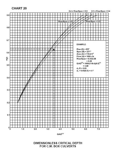
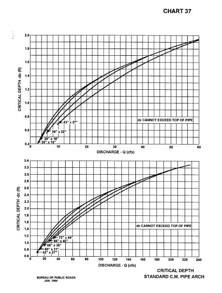
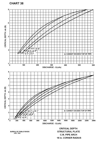
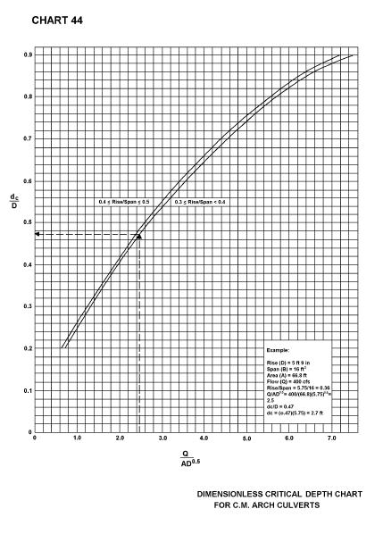
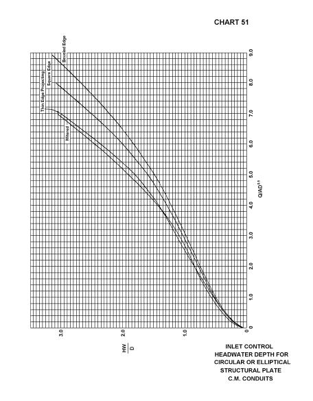
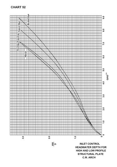
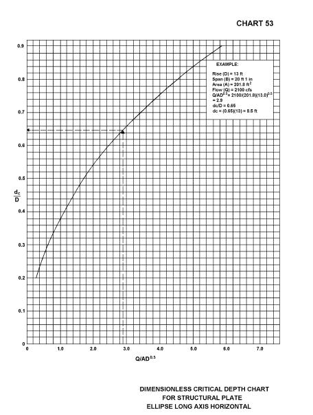
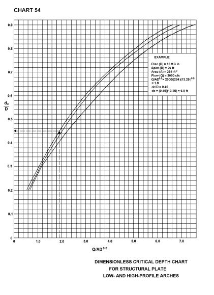
20 4.7 Flood Routing and Culvert Design Introduction Flood routing through a culvert is a practice that evaluates the effect of temporary upstream ponding caused by the culvert's backwater. By not considering flood routing it is possible that the findings from culvert analyses will be conservative. If the selected allowable headwater is accepted without flood routing, then costly over design of both the culvert and outlet protection may result, depending on the amount of temporary storage involved. However, if storage is used in the design of culverts, consideration should be given to: The total area of flooding, The average time that bankfull stage is exceeded for the design flood up to 48 hours in rural areas or 6 hours in urban areas, and Ensuring that the storage area will remain available for the life of the culvert through the purchase of right-of-way or easement Design Procedure The design procedure for flood routing through a culvert is the same as for reservoir routing. The site data and roadway geometry are obtained and the hydrology analysis completed to include estimating a hydrograph. Once this essential information is available, the culvert can be designed. Flood routing through a culvert can be time consuming. It is recommended that a computer program be used to perform routing calculations; however, an engineer should be familiar with the culvert flood routing design process. A multiple trial and error procedure is required for culvert flood routing. In general: (Step 1) (Step 2) (Step 3) (Step 4) (Step 5) A trial culvert(s) is selected A trial discharge for a particular hydrograph time increment (selected time increment to estimate discharge from the design hydrograph) is selected Flood routing computations are made with successive trial discharges until the flood routing equation is satisfied The hydraulic findings are compared to the selected site criteria If the selected site criteria are satisfied, then a trial discharge for the next time increment is selected and this procedure is repeated; if not, a new trial culvert is selected and the entire procedure is repeated. 4.8 Culvert Design Charts and Nomographs Charts 9, 20, 44, and are from the Federal Highway Administration Hydraulic Design of Highway Culverts, Hydraulic Design Series No. 5, All of the figures in this section are from the AASHTO Model Drainage Manual, DIMENSIONLESS CRITICAL DEPTH FOR C.M. BOX CULVERTS 4-18
21 4-19
22 4-20
23 4-21
24 4-22
25 4-23
26 4-24
27 4-25
28 4-26
29 4-27
30 4-28
31 4-29
32 4-30
33 4-31
34 4-32
35 4-33
36 4-34
37 4-35
38 4-36
39 4-37
40 4-38
41 4-39
42 4-40
43 4-41
44 4-42
45 4-43
46 4-44
47 4-45
48 4-46
49 4-47
50 4-48
51 4-49
52 4-50
53 4-51
54 4-52
55 4-53
56 4-54
57 4-55
58 4-56
59 4-57
60 4-58
61 4-59
62 4-60
63 4-61
64 4-62
65 4-63
66 4-64
67 4-65
68 4-66
69 4-67
70 4-68
71 4-69
72 4-70
73 4-71
74 4-72
75 4-73
76 4-74
77 4-75
78 4-76
79 4-77
80 4-78
81 4.9 References American Association of State Highway and Transportation Officials, Highway Drainage Guidelines. American Association of State Highway and Transportation Officials, Model Drainage Manual. Debo, Thomas N. and Andrew J. Reese, Municipal Storm Water Management. Lewis Publishers. Federal Highway Administration, Hydraulics of Bridge Waterways. Hydraulic Design Series No. 1. Federal Highway Administration, Hydraulic Design of Highway Culverts. Hydraulic Design Series No. 5. Federal Highway Administration, Debris-Control Structures. Hydraulic Engineering Circular No. 9. Federal Highway Administration, HY8 Culvert Analysis Microcomputer Program Applications Guide. Hydraulic Microcomputer Program HY8. Federal Highway Administration, Urban Drainage Design Manual. Hydraulic Engineering Circular No. 22. HYDRAIN Culvert Computer Program (HY8). Available from McTrans Software, University of Florida, 512 Weil Hall, Gainesville, Florida U. S. Department of Interior, Design of Small Canal Structures. 4-79
General Information for Culvert Design
 Design Manual Chapter 2 - Stormwater 2E - Culvert Design 2E-1 General Information for Culvert Design A. Introduction A culvert is a conduit under an embankment that transports stormwater from one side
The Basics of Culvert and Inlet Design
 PDHonline Course C619 (8 PDH) The Basics of Culvert and Inlet Design Jerry D. Morrow, PE 2013 PDH Online PDH Center 5272 Meadow Estates Drive Fairfax, VA 22030 6658 Phone & Fax: 703 988 0088 www.pdhonline.org
Indiana LTAP Road Scholar Core Course #10 Culvert Drainage. Presented by Thomas T. Burke, Jr., PhD, PE Christopher B. Burke Engineering, Ltd.
 Indiana LTAP Road Scholar Core Course #10 Culvert Drainage Presented by Thomas T. Burke, Jr., PhD, PE Christopher B. Burke Engineering, Ltd. Objectives Review culvert shapes, end sections, and materials
CHAPTER 5 CULVERT DESIGN
 CHAPTER 5 CULVERT DESIGN HYDRAULICS OF CULVERTS There are two major types of culvert flow: 1) flow with inlet control, and 2) flow with outlet control. For each type, different factors and formulas are
Culvert Design An Overview of the NYS Highway Design Manual Chapter 8
 Seventeenth Statewide Conference on Local Bridges Culvert Design An Overview of the NYS Highway Design Manual Chapter 8 Tuesday, October 25, 2011 Training Session: Culvert Design, Analysis - talk 2 Presented
Culvert Design Basics
 PDHonline Course C287 (4 PDH) Culvert Design Basics Instructor: George E. Thomas, PE 2012 PDH Online PDH Center 5272 Meadow Estates Drive Fairfax, VA 22030-6658 Phone & Fax: 703-988-0088 www.pdhonline.org
APPENDIX J HYDROLOGY AND WATER QUALITY
 APPENDIX J HYDROLOGY AND WATER QUALITY J-1 Technical Report on Airport Drainage, Northern Sector Airport and Ordinance Creek Watershed / Preliminary Creek Constructed Natural Channel Culvert J-2 Preliminary
APPENDIX B HYDRAULIC DESIGN DATA FOR CULVERTS
 TM 5-820-4/AFM 88-5, Chap 4 APPENDIX B HYDRAULIC DESIGN DATA FOR CULVERTS B-1. General. a. This appendix presents diagrams, charts, coefficients and related information useful in design of culverts. The
Chapter 11. Culverts and Bridges Design Checklist for Culvert Design
 Yes No N/A Design Requirements I. GENERAL DESIGN GUIDELINES Chapter 11. Culverts and Bridges A. Culvert design is in accordance with the Culverts chapter of Volume 2 of the UDFCD Manual for additional
HY-8 Version 7.2 Build Date January 17, Federal Highway Administration.
 HY-8 Version 7.2 Build Date January 17, 2012 Federal Highway Administration http://www.fhwa.dot.gov/engineering/hydraulics/software/hy8/index.cfm SIMPLE Simple to use Use for simple culverts and bridges
Technical Report Culvert A Hydraulic Analysis
 DATE: November 3, 2011 Technical Report Culvert A Hydraulic Analysis TO: FROM: RE: Jim Reiser, P.E. Project Manager Parsons Brinckerhoff, Inc. Kurt Killian, P.E., CFM Parsons Brinckerhoff, Inc. Design
Sediment Basin 7E-12. Design Manual Chapter 7 - Erosion and Sediment Control 7E - Design Information for ESC Measures BENEFITS.
 7E-12 Design Manual Chapter 7 - Erosion and Sediment Control 7E - Design Information for ESC Measures Sediment Basin BENEFITS Flow Control Erosion Control Sediment Control Runoff Reduction Flow Diversion
APPENDIX C VEGETATED EMERGENCY SPILLWAY. VERSION 1.0 March 1, 2011
 APPENDIX C VEGETATED EMERGENCY SPILLWAY VERSION 1.0 March 1, 2011 [NOTE: Could use a better photo more clearly showing the emergency spillway in the context of the dam.] SECTION C-1: DESCRIPTION OF PRACTICE
WMS 8.4 Tutorial Hydraulics and Floodplain Modeling HY-8 Modeling Wizard Learn how to model a culvert using HY-8 and WMS
 v. 8.4 WMS 8.4 Tutorial Hydraulics and Floodplain Modeling HY-8 Modeling Wizard Learn how to model a culvert using HY-8 and WMS Objectives Define a conceptual schematic of the roadway, invert, and downstream
OFFICE OF STRUCTURES MANUAL FOR HYDROLOGIC AND HYDRAULIC DESIGN CHAPTER 13 CULVERTS APRIL 2011
 OFFICE OF STRUCTURES MANUAL FOR HYDROLOGIC AND HYDRAULIC DESIGN CHAPTER 13 CULVERTS APRIL 2011 APRIL 2011 Chapter 13 Culverts Table of Contents Foreword.3 13.1 Introduction.. 4 13.2 Policy 6 13.3 Passage
BC Ministry of Forests. March Fish Stream Crossing Guidebook. Forest Practices Code of British Columbia.
 FRST 557 Lecture 7c Bridges and Culverts: Water Velocity and Discharge Lesson Background and Overview: The previous two lessons presented methods for estimating water volume flow at a particular site and
Culvert Design for Low and High Gradient Streams in the Midwest. Dale Higgins, Hydrologist Chequamegon-Nicolet National Forest
 Culvert Design for Low and High Gradient Streams in the Midwest Dale Higgins, Hydrologist Chequamegon-Nicolet National Forest Overview Culvert Design Considerations Hydraulic Terms Culvert Impacts Low
2O-2 Open Channel Flow
 Iowa Stormwater Management Manual O- O- Open Channel Flow A. Introduction The beginning of any channel design or modification is to understand the hydraulics of the stream. The procedures for performing
Access requests to County streets and roadways are processed through one of the following methods:
 13.1 GENERAL APPLICATION PROCESS Access requests to County streets and roadways are processed through one of the following methods: A. Planned Developments may set general locations for access points.
Storm Damage Floating Culverts & Other Inlet Issues
 Storm Damage Floating Culverts & Other Inlet Issues Mark Bailey, PE - Hydraulic Manager, INDOT Dale Sedler, PE - Sr. Hydraulic Engineer, INDOT Road School 2016 What causes a culvert to float? 1. Accumulation
HEC 26 Aquatic Organism Passage Design Manual Evolution & Application
 HEC 26 Aquatic Organism Passage Design Manual Evolution & Application Sven Leon, P.E., Hydraulics Engineer Federal Highway Administration 2015 Alaska Fish Passage Meeting October 13 14, 2015 VTRC, Juneau,
Annex E Bridge Pier Protection Plan
 Annex E Bridge Pier Protection Plan Table E1 Bridge Types and Locations Table E2 Flow Conditions For River Sections Figure E1 Bridge Abutment Protection Figure E2 Bridge Pier Protection Figure E3 Central
APPENDIX A STRUCTURE DESCRIPTIONS AND RATING CURVES
 3 4 5 6 7 8 9 0 3 APPENDIX A STRUCTURE DESCRIPTIONS AND RATING CURVES Kissimmee River Vol December 005 Version Draft 4 3 4 5 6 7 8 9 0 3 4 5 6 7 8 9 0 3 4 5 6 7 8 9 30 3 3 33 34 35 36 37 38 39 40 4 4 43
Culvert Hydraulics: Comparison of Current Computer Models
 Brigham Young University BYU ScholarsArchive All Theses and Dissertations 2007-03-13 Culvert Hydraulics: Comparison of Current Computer Models Elizabeth Anne Thiele Brigham Young University - Provo Follow
USING A LABYRINTH WEIR TO INCREASE HYDRAULIC CAPACITY. Dustin Mortensen, P.E. 1 Jake Eckersley, P.E. 1
 USING A LABYRINTH WEIR TO INCREASE HYDRAULIC CAPACITY Dustin Mortensen, P.E. 1 Jake Eckersley, P.E. 1 Plum Creek Floodwater Retarding Structure No. 6 is located in an area of Kyle, Texas, that is currently
APPENDIX C ESTIMATING SCOUR IN BOTTOMLESS ARCH CULVERTS
 OFFICE OF STRUCTURES MANUAL FOR HYDROLOGIC AND HYDRAULIC DESIGN CHAPTER 11, EVALUATING SCOUR AT BRIDGES APPENDIX C ESTIMATING SCOUR IN BOTTOMLESS ARCH CULVERTS APRIL 2011 APPENDIX C ESTIMATING SCOUR IN
STRUCTURE S-65 PURPOSE SPILLWAY OPERATION
 STRUCTURE S-65 This structure is a reinforced concrete, gated spillway with discharge controlled by three cable operated, vertical lift gates, and a reinforced concrete lock structure with two pairs of
Driveway Design Criteria
 Design Manual Chapter 5 - Roadway Design 5L - Access Management 5L-4 Driveway Design Criteria A. General For efficient and safe operations, access drives and minor public street intersections can be improved
Access Management Standards
 Access Management Standards Section 1: Application of Access Standards This chapter describes the Department's access management standards for access connections on the county roadway system. The standards
Section 5: Pond Outlets
 Section : Pond Outlets Defining and calculating pond outlet devices 8 Minutes Press Space, PageDown, or Click to advance. Press PageUp to reverse. Esc to exit. Right-Click for other options. Outlets Introduction
Advanced Hydraulics Prof. Dr. Suresh A. Kartha Department of Civil Engineering Indian Institute of Technology, Guwahati
 Advanced Hydraulics Prof. Dr. Suresh A. Kartha Department of Civil Engineering Indian Institute of Technology, Guwahati Module - 4 Hydraulics Jumps Lecture - 4 Features of Hydraulic Jumps (Refer Slide
Evaluating Surge Potential in CSO Tunnels
 14 Evaluating Surge Potential in CSO Tunnels Karen E. Ridgway Tunnels are being proposed to control combined sewer overflow (CSO) in numerous cities in the United States and Canada. The tunnels are intended
Plan B Dam Breach Assessment
 Plan B Dam Breach Assessment Introduction In support of the Local Sponsor permit applications to the states of Minnesota and North Dakota, a dam breach analysis for the Plan B alignment of the Fargo-Moorhead
Low Gradient Velocity Control Short Term Steep Gradient Channel Lining Medium-Long Term Outlet Control Soil Treatment Permanent [1]
![Low Gradient Velocity Control Short Term Steep Gradient Channel Lining Medium-Long Term Outlet Control Soil Treatment Permanent [1]](/thumbs/80/80811988.jpg "Low Gradient Velocity Control Short Term Steep Gradient Channel Lining Medium-Long Term Outlet Control Soil Treatment Permanent [1]") Check Dams DRAINAGE CONTROL TECHNIQUE Low Gradient Velocity Control Short Term Steep Gradient Channel Lining Medium-Long Term Outlet Control Soil Treatment Permanent [1] [1] Though not generally considered
Check Dams DRAINAGE CONTROL TECHNIQUE Low Gradient Velocity Control Short Term Steep Gradient Channel Lining Medium-Long Term Outlet Control Soil Treatment Permanent [1] [1] Though not generally considered
STRUCTURE 65-B PURPOSE SPILLWAY OPERATION
 STRUCTURE 65-B This structure is a reinforced concrete, gated spillway with discharge controlled by three cable operated vertical lift gates and a reinforced concrete lock structure with two pairs of sector
Chutes Part 2: Synthetic linings
 s Part 2: Synthetic linings DRAINAGE CONTROL TECHNIQUE Low Gradient Velocity Control Short Term Steep Gradient Channel Lining Medium-Long Term Outlet Control [1] Soil Treatment Permanent [2] [1] s can
OFFICE OF STRUCTURES MANUAL FOR HYDROLOGIC AND HYDRAULIC DESIGN CHAPTER 11 APPENDIX B TIDEROUT 2 USERS MANUAL
 OFFICE OF STRUCTURES MANUAL FOR HYDROLOGIC AND HYDRAULIC DESIGN CHAPTER 11 APPENDIX B TIDEROUT 2 USERS MANUAL APRIL 2011 APRIL 2011 Page 1 Preface TIDEROUT 2, Build 1.22 dated June 29, 2006 is the current
VIRGINIA SOIL AND WATER CONSERVATION BOARD GUIDANCE DOCUMENT ON DAM BREAK INUNDATION ZONE AND INCREMENTAL DAMAGE ANALYSIS AND MAPPING PROCEDURES
 (Approved XXXXX, 2010) Working Draft Version January 14, 2010 VIRGINIA SOIL AND WATER CONSERVATION BOARD GUIDANCE DOCUMENT ON DAM BREAK INUNDATION ZONE AND INCREMENTAL DAMAGE ANALYSIS AND MAPPING PROCEDURES
Outlet Structures T-12
 Description This section provides guidance and details for outlet structures for use primarily with BMPs utilizing sedimentation, (i.e., extended detention basins (EDBs), retention ponds, and constructed
TM /AFM 88-5, Chap Underground hydraulic design Inlets UFC - Drainage In Areas Other Than Airfields
 sults of laboratory research concerning soil infiltration through pipe joints and the effectiveness of gasketing tapes for waterproofing joints and seams are available. 3 6. Underground hydraulic design.
Rock Ramp Design Guidelines. David Mooney MS Chris Holmquist-Johnson MS Drew Baird Ph.D. P.E. Kent Collins P.E.
 Rock Ramp Design Guidelines David Mooney MS Chris Holmquist-Johnson MS Drew Baird Ph.D. P.E. Kent Collins P.E. Rock Ramp Design Guidelines OUTLINE Local and System Interactions with Rock Ramps Ramp Geometry
(Revised February,2005) CULVERTS, BRIDGES, AND FORDS
 CULVERTS, BRIDGES, AND FORDS") GUIDE TO STREAM CROSSINGS (Revised February,2005) CULVERTS, BRIDGES, AND FORDS Culverts, bridges, and fords are all methods used to cross-streams. Culverts are the most common stream crossing structure.
GUIDE TO STREAM CROSSINGS (Revised February,2005) CULVERTS, BRIDGES, AND FORDS Culverts, bridges, and fords are all methods used to cross-streams. Culverts are the most common stream crossing structure.
Memorandum. Dr. Wilbert Odem, Dr. Paul Trotta, and Mr. Justin Ramsey. From: Timothy Mahon, Patrick Belsheim, and Ali Alrayyes.
 Memorandum To: Dr. Wilbert Odem, Dr. Paul Trotta, and Mr. Justin Ramsey From: Timothy Mahon, Patrick Belsheim, and Ali Alrayyes Date: 10/17/2013 Re: Routes Decision Matrix Decision Matrix Methodology The
CALIFORNIA SALMONID STREAM HABITAT RESTORATION MANUAL APPENDIX IX-A CULVERT CRITERIA FOR FISH PASSAGE INTRODUCTION
 APPENDIX IX-A STATE OF CALIFORNIA RESOURCES AGENCY DEPARTMENT OF FISH AND GAME CULVERT CRITERIA FOR FISH PASSAGE For habitat protection, ecological connectivity should be a goal of stream-road crossing
SECTION 1A NEW JERSEY TURNPIKE GEOMETRIC DESIGN
 SECTION 1A NEW JERSEY TURNPIKE GEOMETRIC DESIGN Table of Contents Page No 1A.1 GENERAL...1 1A.1.1 DESIGN CONTROLS...1 1A.2 MAINLINE ROADWAYS...4 1A.2.1 ROADWAY DESIGNATION...4 1A.2.2 DESIGN SPEED...4 1A.2.3
Fish Passage Assessment of Private Stream Crossings on Lower Stonybrook Creek
 Fish Passage Assessment of Private Stream Crossings on Lower Stonybrook Creek Prepared by: Michael Love & Associates In cooperation with: Center for Ecosystem Management and Restoration Funded by: Coastal
Broadly speaking, there are four different types of structures, each with its own particular function:
 3 The selection of structures 3.1 Introduction In selecting a suitable structure to measure or regulate the flow rate in open channels, all demands that will be made upon the structure should be listed.
Aquatic Organism Passage at Road-Stream Crossings CHUCK KEEPORTS FOREST HYDROLOGIST ALLEGHENY NATIONAL FOREST WARREN, PENNSYLVANIA
 Aquatic Organism Passage at Road-Stream Crossings CHUCK KEEPORTS FOREST HYDROLOGIST ALLEGHENY NATIONAL FOREST WARREN, PENNSYLVANIA TOPICS COVERED Aquatic Organism Passage (AOP) Benefits of AOP Crossings
CLEANING, INSPECTION, AND TESTING OF SEWERS
 CLEANING, INSPECTION, AND TESTING OF SEWERS PART 1 - GENERAL 1.01 SECTION INCLUDES A. Cleaning, Inspecting, and Testing Sanitary Sewers B. Cleaning, Inspecting, and Testing Storm Sewers C. Cleaning and
REVETMENTS. Purposes and Operational Constraints. Purposes Erosion control o o. Revetment Design 4/5/2016. CE A676 Coastal Engineering
 REVETMENTS Ijsseldam, the Netherlands Orson P. Smith, PE, Ph.D. Instructor Purposes and Operational Constraints Purposes Erosion control o o Embankment Toe protection for a seawall, retaining wall or other
SELBY CREEK SILVERADO TRAIL CULVERT FISH PASSAGE ASSESSMENT
 SELBY CREEK SILVERADO TRAIL CULVERT FISH PASSAGE ASSESSMENT NAPA COUNTY, CALIFORNIA PREPARED BY NAPA COUNTY RESOURCE CONSERVATION DISTRICT 1303 JEFFERSON ST. SUITE 500B NAPA, CALIFORNIA 94559 WWW.NAPARCD.ORG
Lecture 10 : Sewer Appurtenances
 1 P age Module 8 : Sewer Appurtenances Lecture 10 : Sewer Appurtenances 2 P age The structures, which are constructed at suitable intervals along the sewerage system to help its efficient operation and
SUBMERGED VENTURI FLUME. Tom Gill 1 Robert Einhellig 2 ABSTRACT
 SUBMERGED VENTURI FLUME Tom Gill 1 Robert Einhellig 2 ABSTRACT Improvement in canal operating efficiency begins with establishing the ability to measure flow at key points in the delivery system. The lack
19.1 Problem: Maximum Discharge
 19.1 Problem: Maximum Discharge In partially full channel having an equilateral triangular cross section, the rate of discharge is Q = KAR/3 in which K is a constant, A flow area, R is the hydraulic mean
APPENDIX A STRUCTURE DESCRIPTIONS AND RATING CURVES. Lake Okeechobee & EAA Vol 3 A-i December 2005 Version 1 Draft 4
 1 1 1 1 1 1 1 1 0 1 0 1 0 APPENDIX A STRUCTURE DESCRIPTIONS AND RATING CURVES Lake Okeechobee & EAA Vol A-i December 00 1 1 1 1 1 1 1 1 0 1 from the drainage area served, under a design head of. feet pool
Suitable Applications Check dams may be appropriate in the following situations: To promote sedimentation behind the dam.
 Categories EC Erosion Control SE Sediment Control TC Tracking Control WE Wind Erosion Control Non-Stormwater NS Management Control Waste Management and WM Materials Pollution Control Legend: Primary Category
TECHNICAL MEMORANDUM 002 EMORANNO. 001
 TECHNICAL MEMORANDUM 002 EMORANNO. 001 To: Jack Synder, P.E. EES Consulting From: Mort McMillen, P.E. Paul Larson, SE Date: October 13, 2010 Project: Cc: Taylor Bowen Subject: Technical Memorandum (TM)
Alberta Infrastructure HIGHWAY GEOMETRIC DESIGN GUIDE AUGUST 1999
 Alberta Infrastructure HIGHWAY GEOMETRIC DESIGN GUIDE AUGUST 1999,1'(; A ACCELERATION Data on acceleration from stop D-29 Effects of grade D-35 Intersections D-97, D-99 Lanes D-97, F-5, F-7, F-15, F-21,
Designing Labyrinth Spillways for Less than Ideal Conditions Real World Application of Laboratory Design Methods
 Designing Labyrinth Spillways for Less than Ideal Conditions Real World Application of Laboratory Design Methods Gregory Richards, P.E., CFM, Gannett Fleming, Inc. Blake Tullis, Ph.D., Utah Water Research
Appendix G. Alternative Solutions Details. Krosno Creek Flood Reduction Project PROJECT FILE REPORT CITY OF PICKERING
 Krosno Creek Flood Reduction Project PROJECT FILE REPORT CITY OF PICKERING Appendix G Alternative Solutions Details TMIG THE MUNICIPAL INFRASTRUCTURE GROUP LTD Krosno Creek Flood Reduction Project PROJECT
Figure 1: Graphical definitions of superelevation in terms for a two lane roadway.
 Iowa Department of Transportation Office of Design Superelevation 2A-2 Design Manual Chapter 2 Alignments Originally Issued: 12-31-97 Revised: 12-10-10 Superelevation is the banking of the roadway along
Summary of HEC 18, Evaluating Scour at Bridges FHWA NHI Should really follow HEC 18, but this summary will get you the main points.
 Summary of HEC 18, Evaluating Scour at Bridges FHWA NHI 01-001 Should really follow HEC 18, but this summary will get you the main points. 1: Determine scour analysis variables 2: Analyze long-term bed
MEMORANDUM. TNC Fisher Slough Final Design and Permitting Subject: DRAFT Technical Memorandum: Levee Emergency Spillway Design
 MEMORANUM TNC Fisher Slough Final esign and Permitting Subject: RAFT Technical Memorandum: Levee Emergency Spillway esign To: From: Internal Memorandum For Record Yen Hsu Chen (Tetra Tech) avid Cline (Tetra
CHAPTER 1 STANDARD PRACTICES
 CHAPTER 1 STANDARD PRACTICES OBJECTIVES 1) Functions and Limitations 2) Standardization of Application 3) Materials 4) Colors 5) Widths and Patterns of Longitudinal Pavement Marking Lines 6) General Principles
Transition Submergence and Hysteresis Effects in Three-Foot Cutthroat Flumes
 Transition Submergence and Hysteresis Effects in Three-Foot Cutthroat Flumes Why Measure Water for Irrigation? (You had to ask.) Improve: Accuracy Convenience Economics Water Measurement Manual (Door Prize)
HYDRAULIC JUMP AND WEIR FLOW
 HYDRAULIC JUMP AND WEIR FLOW 1 Condition for formation of hydraulic jump When depth of flow is forced to change from a supercritical depth to a subcritical depth Or Froude number decreases from greater
Presented by Fred Halterman, URS Jennie Agerton, URS
 Presented by Fred Halterman, URS Jennie Agerton, URS What is Eco Friendly Culvert Design? Culvert design that: Maintains connectivity for aquatic organism migration Maintains connectivity for gene flow
Great Lakes Stream Crossing Inventory Instructions
 Great Lakes Stream Crossing Inventory Instructions This document is a guide to completing the Stream Crossing Data Sheet (2/28/11 version). Careful attention to this guidance will ensure consistent crossing
HYDROLOGIC AND HYDRAULIC REPORT PROPOSED CULVERT STRUCTURES SR 194, SECTION 10
 HYDROLOGIC AND HYDRAULIC REPORT PROPOSED CULVERT STRUCTURES SR 194, SECTION 10 RACETRACK ROAD CULVERT OVER THE SPRING RUN & GREEN SPRINGS ROAD CULVERT OVER AN UNNAMED TRIBUTARY TO SPRING RUN BERWICK TOWNSHIP
WASHINGTON CONSERVATION DISTRICT STANDARD OPERATING PROCEDURE (S.O.P.)
") Page 1 of 18 Water Monitoring Program WASHINGTON CONSERVATION DISTRICT STANDARD OPERATING PROCEDURE (S.O.P.) No. 1 FLOW MONITORING Page 2 of 18 Water Monitoring Program Standard Operating Procedure No.
Page 1 of 18 Water Monitoring Program WASHINGTON CONSERVATION DISTRICT STANDARD OPERATING PROCEDURE (S.O.P.) No. 1 FLOW MONITORING Page 2 of 18 Water Monitoring Program Standard Operating Procedure No.
EXAMPLES (OPEN-CHANNEL FLOW) AUTUMN 2018
 AUTUMN 2018") EXAMPLES (OPEN-CHANNEL FLOW) AUTUMN 2018 Normal and Critical Depths Q1. If the discharge in a channel of width 5 m is 20 m 3 s 1 and Manning s n is 0.02 m 1/3 s, find: (a) the normal depth and Froude number
EXAMPLES (OPEN-CHANNEL FLOW) AUTUMN 2018 Normal and Critical Depths Q1. If the discharge in a channel of width 5 m is 20 m 3 s 1 and Manning s n is 0.02 m 1/3 s, find: (a) the normal depth and Froude number
 Dam Modification Report Stingy Run Fly Ash Reservoir Appendix E Spillway System Design Calculations E1: Spillway/Energy Dissipater Design for 100-year Event CHE8273 8 September 4, 2014 Written by: CJW
COST EFFECTIVE STORAGE CAPACITY INCREASE FOR ALUMINA TAILINGS DISPOSAL AREA THROUGH SPILLWAY OPTIMISATION
 COST EFFECTIVE STORAGE CAPACITY INCREASE FOR ALUMINA TAILINGS DISPOSAL AREA THROUGH SPILLWAY OPTIMISATION Abstract Lonie I * Tailings and Dams, GHD Brisbane, QLD, Australia Queensland Alumina Limited operates
CITY OF ROSEVILLE DESIGN STANDARDS
 CITY OF ROSEVILLE DESIGN STANDARDS Section 1 Purpose and Definitions 1-1 Purpose PD 1 1-2 Design Practice PD 1 1-3 Definitions PD 1 Section 2 General Requirements 2-1 Plans by an Appropriate Engineer GR
ANSWERS TO QUESTIONS IN THE NOTES AUTUMN 2018
 ANSWERS TO QUESTIONS IN THE NOTES AUTUMN 2018 Section 1.2 Example. The discharge in a channel with bottom width 3 m is 12 m 3 s 1. If Manning s n is 0.013 m -1/3 s and the streamwise slope is 1 in 200,
CLAIBORNE LOCK AND DAM PERTINENT DATA
 CLAIBORNE LOCK AND DAM PERTINENT DATA GENERAL Location Clarke, Monroe, & Wilcox Counties, Alabama; Alabama River, river mile 72.5 Drainage area Millers Ferry to Claiborne sq. mi. 836 Total drainage area
3-13 UFC - GENERAL PROVISIONS AND GEOMETRIC DESIGN FOR ROADS, STREETS, WALKS, AND OPEN
 maintenance, and erosion. Stability is required to maintain the integrity of the pavement structure, and a slope stability analysis should be conducted for cuts and fills greater than 15 feet. For lower
Transactions on Ecology and the Environment vol 12, 1996 WIT Press, ISSN
 Open boundary condition for unsteady open-channel flow K. Mizumura Civil Engineering Department, Kanazawa Institute of Technology, 7-1 Ogigaoka, Nonoichimachi, Ishikawa Pref. 921, Japan Abstract Initial
22. Specialty Valves.
 22. Specialty Valves. a. Types of Specialty Valves. 1) Use of the following specialty valves is covered in this section: Altitude Valve, Pressure Reducing Valve, Pressure Relief Valve, Swing Check Valve,
Roundabout Design Aid PREPARED BY TRAFFIC AND SAFETY
 Roundabout Design Aid PREPARED BY TRAFFIC AND SAFETY May 2018 Engineering Manual Preamble This manual provides guidance to administrative, engineering, and technical staff. Engineering practice requires
Stormwater Management Pond Design Brief. Greely Village Centre - Commercial Phase - Ultimate Conditions - - City of Ottawa -
 Stormwater Management Pond Design Brief Greely Village Centre - Commercial Phase - Ultimate Conditions - - City of Ottawa - December 2008 Ref: 647-07 J.F. Sabourin and Associates Inc. Water Resources and
City of Roseville Section 13 Design Standards. _Bikeways January 2016 SECTION 13 BIKEWAYS
 SECTION 13 BIKEWAYS 13-1 GENERAL The City of Roseville bikeway standards are designed to insure that transportation and recreational bikeways are constructed in a manner that would provide a safe and comfortable
3. GRADUALLY-VARIED FLOW (GVF) AUTUMN 2018
 AUTUMN 2018") 3. GRADUALLY-VARIED FLOW (GVF) AUTUMN 2018 3.1 Normal Flow vs Gradually-Varied Flow V 2 /2g EGL (energy grade line) Friction slope S f h Geometric slope S 0 In flow the downslope component of weight balances
3. GRADUALLY-VARIED FLOW (GVF) AUTUMN 2018 3.1 Normal Flow vs Gradually-Varied Flow V 2 /2g EGL (energy grade line) Friction slope S f h Geometric slope S 0 In flow the downslope component of weight balances
Design Overview. Section 4 Standard Plans for Design. Pedestrian Access Routes. Pedestrian Access Routes. Overview. Cross Slope
 Design Overview Section 4 Standard Plans for Design Fall, 2017 Ann Johnson, PE Services Brady Rutman, SRF Consulting Group Overview Design Basics Recommendations: The Zone System Driveway Crossings Pedestrian
Developed by: The American Traffic Safety Services Association (ATSSA) 15 Riverside Parkway, Suite 100 Fredericksburg, VA
 15 Riverside Parkway, Suite 100 Fredericksburg, VA") Addendum Developed by: The American Traffic Safety Services Association (ATSSA) 15 Riverside Parkway, Suite 100 Fredericksburg, VA 22406-1022 800-272-8772 This material is based upon work supported by
Addendum Developed by: The American Traffic Safety Services Association (ATSSA) 15 Riverside Parkway, Suite 100 Fredericksburg, VA 22406-1022 800-272-8772 This material is based upon work supported by
Washington State Fish Passage Barrier Removal Projects. Casey Kramer, PE WSDOT State Hydraulics Engineer
 Washington State Fish Passage Barrier Removal Projects Casey Kramer, PE WSDOT State Hydraulics Engineer 2014 National Hydraulic Engineering Conference Iowa City, IA August 20 th, 2014 WSDOT Fish Passage
TOP:001.3 U.S. Fish and Wildlife Service TECHNICAL OPERATING PROCEDURE
 TOP:001.3 March 12, 2015 U.S. Fish and Wildlife Service Marquette Biological Station 3090 Wright Street Marquette, Michigan 49855 U.S.A. and U.S. Fish and Wildlife Service Ludington Biological Station
Design Data 22M. Flotation of Circular Concrete Pipe. w w I = w - x 1000 (3) (SG x 1000)
 (SG x 1000)") Design Data M Flotation of Circular Concrete Pipe There are several installation conditions where there is the possibility that concrete pipe may float even though the density of concrete is approximately.4
Design Data M Flotation of Circular Concrete Pipe There are several installation conditions where there is the possibility that concrete pipe may float even though the density of concrete is approximately.4
Consult with manufacturers concerning permeation of the pipe walls, jointing materials, valve seats, etc.
 Design Manual Chapter 4 - Water Mains 4C - Facility Design 4C-1 Facility Design A. General Water mains and appurtenances, including hydrants and valves, should be provided along all streets including connections
FORMAT FOR SENDING COMMENTS. Title: CRITERIA FOR DESIGN OF CANAL HEAD REGULATORS (Second revision of IS 6531)
") FORMAT FOR SENDING COMMENTS Last Date for Comment is 0 November 009 E-Mail ID for sending comments: rrdash@bis.org.in Document No.: Doc WRD 14 (495)C Title: CRITERIA FOR DESIGN OF CANAL HEAD REGULATORS
FORMAT FOR SENDING COMMENTS Last Date for Comment is 0 November 009 E-Mail ID for sending comments: rrdash@bis.org.in Document No.: Doc WRD 14 (495)C Title: CRITERIA FOR DESIGN OF CANAL HEAD REGULATORS
Slip Lined Culvert Retrofit and Fish Passage
 Brigham Young University BYU ScholarsArchive All Theses and Dissertations 2009-06-10 Slip Lined Culvert Retrofit and Fish Passage Joseph Ray Webb Brigham Young University - Provo Follow this and additional
DISTRIBUTION: Electronic Recipients List TRANSMITTAL LETTER NO. (13-01) MINNESOTA DEPARTMENT OF TRANSPORTATION. MANUAL: Road Design English Manual
 MINNESOTA DEPARTMENT OF TRANSPORTATION. MANUAL: Road Design English Manual") DISTRIBUTION: Electronic Recipients List MINNESOTA DEPARTMENT OF TRANSPORTATION DEVELOPED BY: Design Standards Unit ISSUED BY: Office of Project Management and Technical Support TRANSMITTAL LETTER NO.
DISTRIBUTION: Electronic Recipients List MINNESOTA DEPARTMENT OF TRANSPORTATION DEVELOPED BY: Design Standards Unit ISSUED BY: Office of Project Management and Technical Support TRANSMITTAL LETTER NO.
Experiment (13): Flow channel
: Flow channel") Experiment (13): Flow channel Introduction: An open channel is a duct in which the liquid flows with a free surface exposed to atmospheric pressure. Along the length of the duct, the pressure at the surface
Experiment (13): Flow channel Introduction: An open channel is a duct in which the liquid flows with a free surface exposed to atmospheric pressure. Along the length of the duct, the pressure at the surface
Discussion on the Selection of the Recommended Fish Passage Design Discharge
 Discussion on the Selection of the Recommended Fish Passage Design Discharge Introduction The provision of fish passage is a requirement for most proposed culvert and bridge installations in Alberta, depending
Stormwater Level of Service Study - Phase 2 Flooding Adjacent to Rock Creek
 Stormwater Level of Service Study - Phase 2 Flooding Adjacent to Rock Creek City of Fairway, Kansas Fairway Stormwater Level of Service Study - Phase 2 Project No. 108200 Revision 1 12/6/2018 Stormwater
MODELLING ANCILLARIES: WEIR COEFFICIENTS
 WaPUG USER NOTE No 27 MODELLING ANCILLARIES: WEIR COEFFICIENTS David Balmforth, MWH 1. SCOPE This user note gives advice on the choice of coefficient for overflo eirs and orifices hen modelling storm seage
Road Design Guidelines for Low Impact to Hydrology *
 Five Counties Salmonid Conservation Program P.O. Box 2819 Weaverville, CA 96093 (530) 623-1351 Ext. 5 FAX (530) 623-1353 email: mlancaster@trinitycounty.org Road Design Guidelines for Low Impact to Hydrology
UNDERWATER BRIDGE INSPECTION REPORT STRUCTURE NO CSAH 133 OVER A DITCH ST. LOUIS COUNTY
 UNDERWATER BRIDGE INSPECTION REPORT STRUCTURE NO. 7780 CSAH 133 OVER A DITCH ST. LOUIS COUNTY SEPTEMBER 27, 2012 PREPARED FOR THE MINNESOTA DEPARTMENT OF TRANSPORTATION BY COLLINS ENGINEERS, INC. JOB NO.
Paul Huston, P.E., Design-Build Coordinator Chuck Gonderinger, HDR Engineering. Minnesota Department of Transportation (the Department)
") To: From: Paul Huston, P.E., Design-Build Coordinator Chuck Gonderinger, HDR Engineering Date: March 20, 2001 Subject: Roadway Geometric Design Criteria Project: TH 14/218 Design-Build Project, SP 7408-29,
To: From: Paul Huston, P.E., Design-Build Coordinator Chuck Gonderinger, HDR Engineering Date: March 20, 2001 Subject: Roadway Geometric Design Criteria Project: TH 14/218 Design-Build Project, SP 7408-29,
Spillway Design for Small Dams
 Spillway Design for Small Dams by David E. Fantina, PE Introduction: This course presents an overview of the features that go into the design of spillways for small dams. Small dams in this course refer