Slip Lined Culvert Retrofit and Fish Passage
|
|
|
- Maud Bradford
- 6 years ago
- Views:
Transcription


1 Brigham Young University BYU ScholarsArchive All Theses and Dissertations Slip Lined Culvert Retrofit and Fish Passage Joseph Ray Webb Brigham Young University - Provo Follow this and additional works at: Part of the Civil and Environmental Engineering Commons BYU ScholarsArchive Citation Webb, Joseph Ray, "Slip Lined Culvert Retrofit and Fish Passage" (2009). All Theses and Dissertations This Thesis is brought to you for free and open access by BYU ScholarsArchive. It has been accepted for inclusion in All Theses and Dissertations by an authorized administrator of BYU ScholarsArchive. For more information, please contact scholarsarchive@byu.edu, ellen_amatangelo@byu.edu.
2 SLIP LINED CULVERT RETROFIT AND FISH PASSAGE by Joseph R. Webb A thesis submitted to the faculty of Brigham Young University in partial fulfillment of the requirements for the degree of Master of Science Department of Civil and Environmental Engineering Brigham Young University August 2009
3
4 BRIGHAM YOUNG UNIVERSITY GRADUATE COMMITTEE APPROVAL of a thesis submitted by Joseph R. Webb This thesis has been read by each member of the following graduate committee and by majority vote has been found to be satisfactory. Date Rollin H. Hotchkiss, Chair Date A. Woodruff Miller Date Russell B. Rader
5
6 BRIGHAM YOUNG UNIVERSITY As chair of the candidate s graduate committee, I have read the thesis of Joseph R. Webb in its final form and have found that (1) its format, citations, and bibliographical style are consistent and acceptable and fulfill university and department style requirements; (2) its illustrative materials including figures, tables, and charts are in place; and (3) the final manuscript is satisfactory to the graduate committee and is ready for submission to the university library. Date Rollin H. Hotchkiss Chair, Graduate Committee Accepted for the Department E. James Nelson Graduate Coordinator Accepted for the College Alan R. Parkinson Dean, Ira A. Fulton College of Engineering and Technology
7
8 ABSTRACT SLIP LINED CULVERT RETROFIT AND FISH PASSAGE Joseph R. Webb Department of Civil and Environmental Engineering Master of Science Culverts throughout the country are approaching or are past their original design lives. These baby boomer culverts will need to be repaired, rehabilitated, or replaced. Because entire culvert replacement is so expensive and intrusive, alternate measures to extend the culvert project life are growing increasingly popular. One such method is slip lining, where a sleeve is installed within an existing culvert barrel and stabilized. Plastic pipe sleeves are very popular for slip lining primarily because the plastic material s lower Manning s roughness values allow for the culvert capacity to be maintained despite a reduction in culvert size. Unfortunately, the reduced friction within the barrel can create a barrier to fish passage due to increased water velocities. The increased velocities also cause greater outlet scour which can result in further obstacles to fish passage. These new fish barriers can greatly affect aquatic ecosystems by limiting
9
10 the access that fish have to smaller tributaries used for spawning and rearing access that is critical to the life cycles of many fish. It is suggested that mitigation of the increased velocities should go hand-in-hand with slip lined culvert design projects where fish passage (present or future) is to be considered. Can the demand for hydraulic capacity as well as the demand for fish passage be satisfied? Careful design and installation, coupled with post-project monitoring can result in slip lined culvert retrofits which successfully pass fish. Investigation of federal and state laws and various agency guidelines has informed the creation of a list of culvert conditions which should prompt consideration of slip lined culvert retrofit among other design alternatives. Additionally, a literature review and survey of all U.S. state Departments of Transportation as well as state Fish and Wildlife Departments has shown that there has been very limited experience in providing for fish passage through slip lined culverts. Literature and practice has pointed to the use of baffles and tailwater control weirs for velocity mitigation. Site visits have been made to the few states with this experience to assess developing technologies and record successful and unsuccessful installations. Additional hydraulic analysis using current software suggests general trends in the effects slip lined culvert retrofits on flow type, headwater, velocity as well as the effects of tailwater control weirs. Issues of sustainability, constructability and maintenance, as well as monitoring are addressed.
11
12 ACKNOWLEDGEMENTS I thank the Utah Department of Transportation for providing the funding for this research. I would like to specifically thank Mr. Michael Fazio and Mr. Denis Stuhff for their feedback and help over the project duration. I am grateful to Dr. Rollin H. Hotchkiss for his mentoring over the years, for his patience as I produced this document, and for his friendship. I also want to thank Dr. A. Woodruff Miller and Dr. Russell B. Rader for participating in my graduate committee. Special thanks go to the many respondents to my internet survey, specifically John Perry and Marcin Whitman. I must also thank my wonderful family. Most of all, I thank my lovely wife Steffany. Never did she complain about the long days and nights, or my absence due to site visits and conferences. She continually showed her love and support in word and in deed.
13
14 TABLE OF CONTENTS LIST OF TABLES... ix LIST OF FIGURES... xi 1 Introduction Slip Lined Culvert Retrofit and Fish Passage Slip Lined Culvert Retrofit Fish Passage Culvert Hydraulics Software Analysis Flow Type Headwater Velocity Justifiable Conditions for Slip Lined Culvert Retrofit Literature Review Baffles in Theory Tailwater Control Structures in Theory General Strategy Survey of Current Practices State Departments of Transportation and Fish and Wildlife Departments Survey Results Sustainability Baffles in Practice Tailwater Control Structures in Practice vii
15 3.3 Site Visits John Hatt Creek Retrofit Cape Elizabeth Retrofit Belfast Retrofit Falmouth Retrofit Monitoring Project Summary and Conclusion Problem Survey of Current Practices Conclusions Recommendations Culvert Test Facility Follow-up Industry Survey References Appendix A Hydraulic Analysis Data Appendix B List of Acronyms Appendix C Results of Internet Survey Appendix D Monitoring and Maintenance Plan Appendix E Utah State DNR DWR Sensitive Species List viii
16 LIST OF TABLES Table 2-1: Description of Barriers to Fish Passage and Possible Impacts (Hotchkiss and Frei 2007)...6 Table 2-2: Range of Original and Retrofit Culvert Sizes, and Discharges Used in HY-8 Simulations...7 Table 2-3: Flow Types of Original Culverts at Various Slopes Table 2-4: Changes in Culvert Flow Type, Headwater and Outlet Velocities Due to Slip Lined Culvert Retrofit Table 2-5: Changes in Culvert Flow Type, Headwater and Outlet Velocities Due to Slip Lind Culvert Retrofit with Baffles ix
17 x
18 LIST OF FIGURES Figure 2-1: A 1-S2n drawdown curve in culvert on steep slope (Normann et al. 2005, adapted) Figure 2-2: A 2-M2c drawdown curve in culvert on mild slope (Normann et al. 2005, adapted) Figure 2-3: Limit slope for various culvert materials. PVC (n=0.011), CSP/CHDPE (n=0.024), Smooth HDPE/Concrete (n=0.012), CAP (n=0.031)...11 Figure 2-4: Limit slope for possible culvert liner materials Figure 2-5: Change in headwater for various culvert sizes at various slopes with no tailwater channel Figure 2-6: Change in headwater for various culvert sizes at various slopes with a tailwater channel of the same slope Figure 2-7: Boxplot of the percent change in headwater at various slopes due to slip lined culvert retrofit with no tailwater channel Figure 2-8: Boxplot of the percent change in headwater at various slopes due to slip lined culvert retrofit with a tailwater channel Figure 2-9: Change in headwater due to slip lined culvert retrofit for slopes 1-5% in both "No Tailwater" (No TW) and "Tailwater" (TW) conditions Figure 2-10: Change in outlet velocity for various culvert sizes at various slopes with no tailwater channel Figure 2-11: Change in outlet velocity for various culvert sizes at various slopes with a tailwater channel at the same slope Figure 2-12: Boxplot of the percent change in outlet velocity at various slopes due to slip lined culvert retrofit with no tailwater channel Figure 2-13: Boxplot of the percent change in outlet velocity at various slopes due to slip lined culvert retrofit with a tailwater channel Figure 2-14: Diagram of the effect of grade controls on water surface profile and existing streambed xi
19 Figure 2-15: Looking towards culvert outlet. Longitudinal channel on right. (CALTRANS 2007)...31 Figure 2-16: Looking at culvert outlet. Longitudinal Channel on left. (CALTRANS 2007)...31 Figure 3-1: Various techniques for velocity mitigation in stream crossings Figure 3-2: Failure due to insufficient anchoring. (CALTRANS 2007)...37 Figure 3-3: Debris caught on a baffle. (CALTRANS 2007)...37 Figure 3-4: HDPE baffles plastic welded into an HDPE culvert sleeve Figure 3-5: Erosion flanking tailwater control weirs at John Hatt Creek Figure 3-6: Outlet of slip lined culvert retrofit of John Hatt Creek showing corner baffles and one of the three tailwater control barriers Figure 3-7: Culvert retrofit on Alewife Creek near Cape Elizabeth, Maine. Tailwater weir is submerged Figure 3-8: Cuvlert retrofit outside Belvast, Maine, showing tailwater cotrol weir Figure 3-9: Welding of culvert segments. Attachment used as opportunity to provide anchoring for baffle...44 Figure 3-10: View of all baffles within Belfast, Maine culvert retrofit Figure 3-11: Baffles within Belfast, Maine culvert retrofit Figure 3-12: Design detail of Belfast, Maine culvert baffles. (Courtesy of MDOT)...46 Figure 3-13: Design detail of Belfast, Maine tailwater control weirs. (Courtesy of MDOT)...46 Figure 3-14: Outlet of Falmouth, Maine slip lined culvert retrofit. Rock tailwater grade control also shown Figure 3-15: Possible fish barrier downstream of Falmouth culvert. The presence of this very old retention structure allowed for experimental retrofit Figure E-1: Introduction to UDWR SSL Figure E-2: List of Fish on UDWR SSL xii
20 1 Introduction The vast majority of pipe culverts in the United States were built over 40 years ago, during a massive transportation infrastructure upgrade; our culverts are reaching a kind of middle age. A Transportation Research Board Research Needs Statement explains that the highway infrastructure is characterized by a huge inventory of damaged and decaying culverts. Because entire culvert replacement is so expensive and intrusive, alternate measures to extend baby boomer culvert life are growing increasingly popular. One such method is slip lining, where a sleeve usually plastic is installed, or slipped, within the existing culvert barrel and stabilized. The sleeve s lower roughness value allows for the smaller pipe to convey the same capacity. This slip lining method is attractive because it does not require any excavation of the existing pipe and roadway fill, providing an opportunity for culvert replacement without the undesired disruption to highway traffic, not to mention the advantage of rehabilitating the culvert without less right of way concerns. Culvert and pipe fabricators have begun to design and manufacture product conducive to this new technology (TRB 2007). The huge inventory of aging culverts was likely designed solely on the basis of peak design flows, and did not take into account fish passage. Many of these culverts have turned out to be significant barriers to fish movement. In 1973 the United States Government signed into law the Endangered Species Act (ESA). Once a species is listed as threatened or endangered, the ESA requires that critical habitat be designated for that species, including areas necessary to recover the species. Federal agencies are forbidden from authorizing, funding, or carrying out any action which destroys or adversely modifies" critical habitat (USC 1973). Unfortunately, the increased velocities due to slip lined culvert retrofit can result in further obstacles to fish passage. These new fish 1
21 barriers can greatly affect aquatic ecosystems by limiting the access that fish have to smaller tributaries used for spawning and rearing access that is critical to the life cycles of many fish. It is suggested that mitigation of the increased velocities should go hand-in-hand with slip lined culvert design projects where fish passage (present or future) is to be considered. Can the demand for hydraulic capacity as well as the demand for fish passage be satisfied? To this point, there has been very limited experience in providing for fish passage through slip lined culverts. The objective of this paper is to introduce slip lining as an option for culvert retrofit and discuss fish passage implications associated with this method. Additionally, this paper contains a review of the currently available literature on mitigation techniques, a survey of transportation and fisheries agencies who have utilized mitigation techniques, and reports on visits to various project locations to identify successful implementation of slip lined culvert retrofits. Finally, this report includes recommendations for conditions where slip lined retrofits should be considered, as well as suggested methods for providing for fish passage in slip lined culverts. 2
22 2 Slip Lined Culvert Retrofit and Fish Passage This section describes the slip lined culvert retrofit process and the advantages of this method when compared to conventional culvert replacement. Additionally, this section outlines concerns that this method is counterproductive to fish passage, including exploring the affects that this method has on overall culvert hydraulics. Finally, this section describes conditions where slip lined culvert retrofit may be considered, as well as a review of mitigation measures promoted in available literature. 2.1 Slip Lined Culvert Retrofit Slip lining involves three major steps. First, the existing culvert must be inspected and prepared for lining. This process includes flushing or cleaning the existing culvert to eliminate obstructions. Second, a smooth plastic (generally) pipe end is placed into the culvert and pushed through the culvert. Finally, the culvert ends are capped and the annular spaces between the existing culvert and the new liner are grouted to fix the liner in place and provide additional structural support (Campbell 1995). These culvert lining techniques often reduce construction costs by 50-75% (DeMarco and Muenchmeyer 1993, Campbell 1995). Additionally, slip lined retrofits often take half the time of regular culvert replacement, often with only very minor to no traffic impedance (DeMarco and Muenchmeyer 1993). Recent Utah Department of Transportation (UDOT) literature estimates a savings of $35,000 per culvert and a reduction in traffic costs and gives specific strategies for slip lined retrofits given various conditions. The same report states that Rehabilitating, rather than replacing culverts, will become more common in Utah because existing aging culvert are failing and population growth makes traffic control more difficult. (UDOT 2008) 3
23 Public Works Monthly (Campbell 1995) describes the rehabilitation of two stream crossings using a slip lining technique at the Kennedy Space Center. The first crossing involved twin corrugated metal culverts. These culverts were severely rusted out and on one culvert the bands had pulled apart, creating a severe washout on the downstream side that caused the headwall to drop. Both shoulders...had experienced severe erosion caused by migration of soil into the deteriorated culvert. The road itself was in danger of collapse. EG & G Florida, Inc., the company which maintains the grounds at the Kennedy Space Center, chose to replace the 54-in. (1.37-m) corrugated metal culverts with liners whose interior dimensions are 42-in. (1.07-m). The branch manager for EG & G explained, Relining culverts rather than replacing them has several advantages. Cost savings average about 65 percent versus replacement It is also important not to have to disrupt traffic on the heavily traveled roads...this problem is solved by relining rather than replacing the culverts In many cases flow capacity remains the same as the original culvert and often flows can be increased by the lining procedure. Once the liners had been inserted, the annular space between the original culverts and the retrofitted liners were grouted to prevent any road collapse due to soil migration. Kustom Construction Co. was given charge to rehabilitate culverts in 13.3 miles (21.4 kilometers) of the Tri-State Toll Road north of Chicago s O Hare International Airport. A total of in. (38-cm) corrugated steel culverts had rusted through over their 35 years. Kustom Construction selected Ace Pipe Cleaning, Inc. and slip-lining. The liner s walls, ½-in. (1.27-cm), high-strength black polyethylene, resistant to acids and corrosion, last indefinitely (Anon. 1994). The entire process of assembly and positioning averaged two liners per 6-hour day and in many cases, a three-man subcontractor team installed up to seven liners per 6-hour day. Though the chosen liners were only 13-in. (33-cm) in diameter, their low coefficients of friction allowed even greater flows than the previous culvert. Their purchase, assembly, and placement costs totaled only a fraction of excavating and other methods considered and... traffic was never impeded (Anon. 1994). It is estimated that the project took one quarter of the man-hours and as little as 1/3 of the total time necessary for a conventional culvert replacement. 4
24 2008): UDOT has recommended slip lined culvert retrofits be considered when (UDOT 1. Daily traffic exceeds 1000 vehicles. 2. Maximum cover over a culvert is more than 4 ft (1.22-m). This requires benching or shouldering when excavating, which increases the potential for workplace hazards. 3. The detour route for the work area is greater than 20 minutes. Conventional dig and replace projects require costly pavement repairs and complex traffic control. 2.2 Fish Passage The 1973 ESA requires that critical habitat be designated for all listed species and that federal agencies are forbidden from authorizing, funding, or carrying out any action which "destroys or adversely modifies" this critical habitat. Therefore, all listed aquatic organisms are a concern when considering culvert design and culvert retrofit, though this report focuses solely on fish passage. Although slip lined culvert retrofits may be extremely appealing when considering cost, time, and culvert discharge capacity, this method is fraught with fish passage issues, and therefore, basic slip lined retrofits can be at odds with ESA requirements. The same hydraulic characteristic that makes slip line retrofit possible increased velocities due to low roughness can be a barrier to fish passage, and exacerbate several other barrier processes. The decreased roughness can cause increased scouring at the outlet of the culvert, causing it to be perched. There are several reasons that a culvert may represent a fish passage barrier. These barriers and possible impacts are found in the recent Federal Highway Administration document Design for Fish Passage at Roadway-Stream Crossings: Synthesis Report (Hotchkiss and Frei 2007) and shown in Table
25 Table 2-1: Description of Barriers to Fish Passage and Possible Impacts (Hotchkiss and Frei 2007) Table 2. Description of Barriers to Fish Passage and Possible Effects (from FHWA 2007) Barrier Type Description Impact Drop Velocity Turbulence Length Depth Debris Cumulative Drop at outlet exceeds fish jumping ability, or jump pool is insufficient to generate sufficient thrust. High velocity exceeds fish swimming ability. Turbulence within culvert prevents fish from entering, or confuses sense of direction. Low flow depth causes fish not to be fully submerged. Caught within a culvert, debris can block flow, or portions of flow. Series of culverts, each of which stresses fish during passage. Fish cannot enter structure, can be injured, or will expend too much energy entering the structure to traverse other obstacles. Fish tire before passing the crossing. Fish do not enter culvert, or are unable to successfully navigate the waterway. Fish may not enter structure due to darkness. Fish may fatigue before traversing the structure. Fish will be unable to swim efficiently or unable pass the structure. Fish may not be able to pass by debris, or constricted flow may create a velocity or turbulence barrier within the culvert. Group of culverts, each marginally passable, may be a combined barrier. 2.3 Culvert Hydraulics Software Analysis This section focuses on the methods and results of software based hydraulic analysis which was done in an attempt to determine ranges of flow characteristics which would make fish passage possible in slip lined culverts. It was desired to determine ranges of specific gradients, culvert diameters, and discharges that, when used in combination, would make slip lining untenable for fish passage. Specifically, this analysis asked the following questions: When will a slip lined retrofit change culvert flow types from outlet to inlet control? How will a slip lined culvert retrofit change culvert headwater? How will a slip lined retrofit change culvert velocities? What recommendations can be made when analyzing these effects in combination? To answer these questions, over 3,000 computer simulations were run on the Federal Highway Administration (FHWA) culvert hydraulics software program Win HY-8 (FHWA 2008). The parameters used for possible culvert and liner diameters are shown in the table below. Culvert liner sizes below 7-ft (2.14-m) in diameter are taken from a UDOT/Utah State University Report (UDOT 2008) and are shown in Table
26 Table 2-2: Range of Original and Retrofit Culvert Sizes, and Discharges Used in HY-8 Simulations Original Culvert Inner Diameter (ft) Liner Outer Diameter (ft) Space Between Liner and Culvert (in.) Range of Discharges Simulated (cfs) The material used for original culverts was corrugated steel pipe (CSP) (n=0.024), while the liner material used is smooth high density polyethylene (HDPE) (n=0.012). All culverts were 100-ft (30.5-m) long. Instead of slightly perching the liner inlet invert, as would be the case immediately after construction, the liner in these simulations are placed flush with streambed level, anticipating that deposition at the culvert inlet would create the condition simulated, and that this condition would be in effect during the vast majority of the culvert retrofit s design life. 7
27 The discharges shown in the above table were used to analyze flow type and velocity changes due to slip lined culvert retrofit, and were chosen to simulate expected fish passage velocities. Headwater analysis was done using fish passage discharges as well as discharges that would better represent design discharges. The highest velocities used in existing culverts for the simulations are 8-ft/s (2.44-m/s). Literature has shown the burst speed for Utah species is not expected to be higher than 6-ft/s (1.83-m) (Aedo et al. 2008, Bell 1991), while strong swimming fishes not found in Utah, such as adult steelhead, may have burst speeds of as much as 16-ft/s (4.88-m) (Bell 1991). Two tailwater conditions were: first no tailwater, simulating a perched culvert outlet; and second, tailwater produced is a rectangular channel with a bottom depth much greater than the culvert diameter and a slope equal to that of the culvert slope with a Manning s n of This number corresponds with an average excavated or dredged channel, a fairly clean natural channel, or a channel constructed from concrete poured on irregular excavated rock (Chow 1959) Flow Type The first question answered by these simulation is related to flow type, specifically whether slip lining culvert retrofits would change a culvert from inlet control to outlet control or vice versa. A culvert which exhibits inlet control has free supercritical surface flow throughout the barrel and the type of barrel does not influence headwater. Only the inlet makes a difference. On the other hand, several factors influence headwater elevation in outlet control. These are entrance type, and because flow is subcritical, barrel roughness, culvert length and tailwater elevation. In cases where outlet control exists, changing barrel roughness will have a more significant effect on culvert velocities than will cases where inlet control exists. Although flow through a culvert barrel can be complex, two dominant profiles were exhibited in those simulations, a 1-S2n drawdown curve and a 2-M2c drawdown curve. The 1-S2n drawdown curve is shown within a culvert in Figure

. The flow in this culvert condition is entirely subcritical, with neither the inlet nor outlet submerged.")
28 Figure 2-1: A 1-S2n drawdown curve in culvert on steep slope (Normann et al. 2005, adapted). In the 1-S2n condition, neither the inlet nor the outlet end of the culvert is submerged. The flow passes through critical depth just downstream of the culvert entrance and the flow in the barrel is supercritical. The barrel flows partly full over its length and the flow approaches normal depth at the outlet end. (Normann et al. 2005) The other common flow type is 2-M2c, which is shown in Figure 2-2. Figure 2-2: A 2-M2c drawdown curve in culvert on mild slope (Normann et al. 2005, adapted). The flow in this culvert condition is entirely subcritical, with neither the inlet nor outlet submerged. This is an attractive condition for fish passage. Full descriptions of other flow types may be found in HDS-5 (Normann et al. 2005). 9
29 The simulations show that culverts 20-ft in diameter and smaller do not typically exhibit outlet control in discharges that produce velocities where fish passage is a possibility. The simulations show that outlet control is exhibited in culverts with a diameter of 11-ft (3.35-m) or smaller when at a slope of 1% or less, as well as small culverts on a 2% slope. This is shown in Table 2-3: Table 2-3: Flow Types of Original Culverts at Various Slopes Original Culvert Diameter (ft) Flow Types S = 0.01 S = 0.02 S = 0.03 S = 0.04 S = M2c, 7-M2c 3 2-M2c 1-S2n, 2-M2c, 7-M2c 1-S2n, 5-S2n, 2-M2c 1-S2n, 5-S2n 1-S2n, 5-S2n 1-S2n, 5-S2n 1-S2n 1-S2n 1-S2n 4 2-M2c 1-S2n 5 2-M2c 6 2-M2c 7 2-M2c 8 2-M2c 9 2-M2c 10 2-M2c 11 2-M2c, 1-S2n 12 1-S2n 1-S2n 1-S2n 1-S2n 1-S2n The preceding table shows that variable flow types are produced in culverts of small diameter. The flow type of 2-ft (0.61-m) culverts is generally inlet controlled (1-S2n, 5- S2n) for discharges under 15-cfs ( cms) and changes to outlet control (7-M2c, 2- M2c) for slopes of 1% or 2% and discharges over 15-cfs (0.057-cms). All culvert simulations done on 1% slope and under 11-ft (3.35-m) in diameter exhibited outlet 10
30 Limit Slope (S L) control at each discharge simulated. Each corrugated steel pipe culvert which exhibited outlet control initially shows a change from outlet to inlet control when retrofitted. Other than these cases, all cases studied exhibited inlet control before and after retrofit. Subcritical flows are more beneficial to fish passage. Because of this, it is helpful to know the limit slope, or smallest critical slope, for a given channel shape and roughness. This is the slope, that for a given channel shape and material, produces subcritical flow no matter what the discharge. The limit slope for circular channels has been derived (Rao and Sridharan 1970) as: 2 n S L (2-1) d 1 3 where: n = Manning s Roughness Value d = Culvert diameter (ft) The limit slope curves for various materials and diameters are shown on Figure Culvert Diameter (ft) PVC (n=0.011) CSP/CHDPE (n=0.024) Smooth HDPE/Concrete (n=0.012) CAP (n=0.031) Figure 2-3: Limit slope for various culvert materials. PVC (n=0.011), CSP/CHDPE (n=0.024), Smooth HDPE/Concrete (n=0.012), CAP (n=0.031) 11
31 Limit Slope (SL) All combinations of slope and culvert diameter which fall above the lines produce supercritical flow, while subcritical flow would be found below the lines. Only the limit slope curves for liner materials are shown enlarged in Figure Culvert Diameter (ft) PVC (n=0.011) Smooth HDPE/Concrete (n=0.012) Figure 2-4: Limit slope for possible culvert liner materials. This figure shows only the limit slopes for Smooth HDPE (n = 0.012) liners as well as PVC (n = 0.011) liners. A combination of slope and liner diameter above the respective lines will produce supercritical flow, while subcritical flow would be created by a combination of slopes and culvert diameters below the lines. Design engineers can use this relationship to identify whether a given liner and slope combination will naturally produce subcritical flow, or if mitigation measures would be necessary to produce such flows. Although inlet control exists in most cases before and after retrofit within velocities conducive to fish passage, it should be noted that none of these simulations included any external or internal energy dissipaters, such as culvert baffles, or tailwater weirs. It is expected that these stream crossing accoutrements installed along with a slip 12
32 lined retrofit would often cause a shift from inlet to outlet control, which may result in an unacceptable increase in headwater depth at the entrance for the flood design discharge. Due to the number, sizes and sheer variety of energy dissipators available, indepth hydraulic analysis with these structures is beyond the scope of this study. References to application and design of these structures may be found under the section heading Survey of Current Practices, as well as the references section of this document Headwater The second question to be answered by the software analysis is regarding changes in headwater due to culvert slip lined retrofit. As is stated above, hydraulic theory states that the headwater is not influenced by barrel roughness in inlet control conditions. Because this culvert hydraulics analysis is constrained by fish swimming performance velocities, the vast majority of initial culvert conditions are tested at relatively low flows and exhibit inlet control. The headwater therefore, is not influenced by the change in barrel roughness, which is one of the two changes made in slip lined culvert retrofit, along with culvert diameter. However, headwater is affected by inlet conditions, which are changed due to the reduction in the culvert diameter. How sensitive is headwater to the change in inlet conditions? Figure 2-5 and Figure 2-6 show the percent change in headwater due to slip lined culvert retrofit at a range of original culvert diameters of 2-ft to 20-ft. Figure 2-7 and Figure 2-8 are commonly referred to as boxplots, or whiskerplots, which show the sample minimum, the sample median and sample maximum. The box is defined by the upper quartile and lower quartile of the data, meaning that 50% of the samples are contained within the box. The dash in the middle of the box represents the sample median. These figures show the percent change in headwater due to slip lined culvert retrofit at a range of slopes from 1% to 5%. 13
33 Change in Headwater Change in Headwater 15% 10% 5% 0% -5% -10% -15% Original Culvert Diameter (ft) S = 0.01 S = 0.02 S = 0.03 S = 0.04 S = 0.05 Figure 2-5: Change in headwater for various culvert sizes at various slopes with no tailwater channel. 20% 15% 10% 5% 0% -5% -10% -15% Original Culvert Diameter (ft) S = 0.01 S = 0.02 S = 0.03 S = 0.04 S = 0.05 Figure 2-6: Change in headwater for various culvert sizes at various slopes with a tailwater channel of the same slope. 14
34 Change in Headwater Change in Headwater 35% 30% 25% 20% 15% 10% 5% 0% -5% -10% -15% Culvert Slope (ft/ft) Figure 2-7: Boxplot of the percent change in headwater at various slopes due to slip lined culvert retrofit with no tailwater channel. 15% 10% 5% 0% -5% -10% -15% Culvert and Channel Slope (ft/ft) Figure 2-8: Boxplot of the percent change in headwater at various slopes due to slip lined culvert retrofit with a tailwater channel. 15
35 Given that the study comprises culverts which are almost exclusively exhibiting inlet control, it is not surprising that the simulation results show a minimal difference between the headwaters of the No Tailwater samples and the with Tailwater samples. Similarly, it is not surprising that that smaller culverts, as well as culverts that are on a shallower gradient channel experience greater changes in headwater. Indeed, culverts that are greater than 3-ft (0.91-m) in diameter and are on 2% or greater slopes experience almost no change in headwater due to slip lined retrofits until a culvert size of roughly 17-ft (5.18-m), when the headwater decreases as culvert size increases. The nonuniformity in low slopes and smaller diameters is a result of the flow type conditions described in the previous section. The 1% slope samples show an increase in headwater up to the 11-ft (3.35-m) diameter culvert, corresponding with the range of sizes which exhibit outlet control. As is stated earlier, these simulations exhibit outlet control conditions, which cause the sensitivity to both inlet conditions and barrel roughness. This figure shows that, excluding culverts on a 1% slope, all culverts between 3-ft (0.91- m) and 20-ft (6.1-m) experience less than 5% headwater change due to slip lined retrofits. The figures do show however, that culverts on slopes of 2% or greater show more headwater variation due to slip lined retrofits at smaller culvert sizes than do those on 1% slopes. Analysis of Figure 2-7 and Figure 2-8 show that while greater total variation exists among the steeper slopes, variation within the first and third quartiles is quite low, and median percent headwater changes for these slopes is very near zero. On the other hand, total variation between maximum and minimum headwater changes at 1% slope is quite low; variation within the first and third quartiles is greater. Additionally, it is important to note that slip lined culvert retrofits on a 1% slope tend to reduce headwater elevation. Retrofits on 2-5% slopes generally result in headwater changes between -2% and +2%, and generally never more than 12% except in perched culvert conditions generally a fish passage barrier where increases of up to 30% are calculated. The previous four figures, when understood in combination, show that while culverts on 2%-5% slopes are less sensitive to slip lined culvert retrofit over most sizes 16
36 (4-ft to 20-ft diameter, 1.22-m to 6.1-m diameter), the increase in headwater levels on culverts smaller than 4-ft (1.22-m) can be up to 30%. Culverts on 1% slopes are more stable over this range of smaller culverts, but not over all culvert sizes analyzed. However, this instability in culverts on 1% slopes is a result of large decreases in headwater elevations, which are also found in culverts of 17-ft (5.18-m) diameter and larger, and would generally be considered a beneficial effect. Admittedly, headwater changes at fish passage discharges is secondary to headwater changes at design discharges and high flows, as basic design based on human and structural safety includes accounting for the possibility of headwater changes. The maximum allowable headwater depth is generally prescribed by policy. The allowable headwater will be limited by one or more of the following: non-damaging to upstream property, below the edge of the shoulder, a maximum of 0.5 ft (0.15 m) increase over the existing 100-year flood elevation in FEMA mapped floodplain, a maximum of 1 ft (0.30 m) increase over the 100-year flood elevation in unmapped floodplains, equal to the elevation where flow diverts around the culvert (UDOT 2004) Although the allowable headwater is unique for each stream crossing, an analysis was done on headwater changes due to retrofit at flows which would produce submerged inlets, but not submerge the outlets. Over the range of culvert diameters already outlined, discharges were calculated which would cause a headwater equal to 1.5 times the culvert diameter. This ratio of headwater to culvert diameter typically results in either partly full flow with rapid flow at the inlet or full flow with a free outfall. Once obtained, this same discharge was run through a slip lined HDPE culvert sleeve to calculate the change in headwater due to slip lined culvert retrofit at high flows. The results are shown in Figure 2-9: 17
37 Change in Headwater (ft) % No TW 2% No TW 3% No TW 4% No TW 5% No TW 1% TW 2% TW 3% TW 4% TW 5% TW Original Culvert Diameter (ft) Figure 2-9: Change in headwater due to slip lined culvert retrofit for slopes 1-5% in both "No Tailwater" (No TW) and "Tailwater" (TW) conditions. This figure shows that changes in headwater at high flows is not sensitive to tailwater conditions or channel slope at original culvert diameters greater than 3-ft (1.52- m). The change in headwater is quite sensitive to original culvert diameter, and decreases nearly linearly as culvert diameter increases from 7-ft (2.13-m) to 20-ft (6.10-m). It is also important to note that nearly every retrofit done on a culvert with diameter smaller than 12-ft (3.66-m) experienced an increase in headwater, including a few producing increases of greater than the 1-ft (0.30-m) prescribed by policy. Culverts with original diameters of 12-ft (3.66-m) or greater experience decreases in headwater when retrofitted Velocity The third question to be answered by the software analysis is regarding changes in velocity due to culvert slip line retrofit. Perhaps the most basic principle of fluid dynamics is that total flow is equal to the cross sectional area of flow multiplied by the velocity (Q= V * A). Based on this fundamental principle, we expect that, given a constant flow, reducing the culvert diameter when retrofitting a culvert will result in an 18
38 Change in Velocity Change in Velocity increase in velocity. The question is then How much will velocities increase? The following figures show changes in culvert velocity due to slip lining at the slopes simulated. 120% 100% 80% 60% 40% 20% 0% Original Culvert Diameter (ft) S = 0.01 S = 0.02 S = 0.03 S = 0.04 S = 0.05 Figure 2-10: Change in outlet velocity for various culvert sizes at various slopes with no tailwater channel. 120% 100% 80% 60% 40% 20% 0% Original Culvert Diameter (ft) S=0.01 S=0.02 S=0.03 S=0.04 S=0.05 Figure 2-11: Change in outlet velocity for various culvert sizes at various slopes with a tailwater channel at the same slope. 19
39 Change in Velocity Change in Velocity 120% 100% 80% 60% 40% 20% 0% Culvert Slope (ft/ft) Figure 2-12: Boxplot of the percent change in outlet velocity at various slopes due to slip lined culvert retrofit with no tailwater channel. 120% 100% 80% 60% 40% 20% 0% Culvet and Channel Slope (ft/ft) Figure 2-13: Boxplot of the percent change in outlet velocity at various slopes due to slip lined culvert retrofit with a tailwater channel. 20
40 Figure 2-10 and Figure 2-11 show that slip lined culvert retrofits do indeed result in increased culvert velocity. Aside from those culverts on 1% slopes, culverts originally having between 2-ft and 3-ft diameter exhibit almost exactly the same increase in velocity due to slip lined retrofits. The variation in increased velocity is exaggerated as original culvert size increases, though the average percent change in velocity is consistently around 60% for all culvert sizes. Is this percentage change in velocity also generally consistent for all slopes? Figure 2-12 and Figure 2-13 show again that the median increase in velocity is near 60%, with the median for slip lined retrofits on 1% slopes near 50%. Designers can expect that most slip lined retrofits will cause an increase in outlet velocity of around 60% with the understanding that increases of more than 100% or less than 25% are possible. Headwater, velocity, flow type and flow depth are four primary metrics used assess a stream crossing for fish passage compliance. Some of the more basic variables which affect these values include: Culvert Size Culvert Material Culvert Slope Culvert Length Stream Slope Stream Discharge Tailwater Channel Conditions Each variable in this list has an enormous range of possible values, and while some are more limited (culvert material, culvert size), some have an infinite number of possible values (stream discharge, stream slope, tailwater channel conditions). Each stream crossing will have unique values has a unique combination of these values which must be taken into account as unique designs for fish passage are developed. Unfortunately, the extensive calculations and analysis of the software based hydraulic analysis of slip lined culverts lacks sufficient evidence to simplify this process significantly through the identification of less significant variables. This analysis does not support a 21
41 recommendation that certain ranges of flow characteristics should not be considered for slip lined culvert retrofit for fish passage. Although specific gradients, culvert diameters, and discharges are not derived from this analysis, the results do provide general trends which should be considered in retrofit design, particularly the effects of slip lining on velocity. Slip lined culvert retrofits commonly result in velocity increases of 60%. Mitigation of these increased velocities is essential if slip lined retrofits are to provide for fish passage. 2.4 Justifiable Conditions for Slip Lined Culvert Retrofit The most effective way to provide fish passage is through full culvert replacement, applying relevant fish passage design criteria. While slip lined culvert retrofits are significantly more inexpensive than other culvert replacement options, and may prove to provide fish passage, analysis has shown that slip lined culvert retrofits significantly increase the outlet velocity of a stream crossing. This increase will generally make the crossing a barrier to fish passage. Given this automatic increase in velocities which will occur when a slip lined retrofit is performed, it is essential to discuss mitigation techniques which can enable fish passage and therefore, compliance to Federal and State Laws. It should again be noted that while full ecological connectivity is impossible without fully spanning the entire active channel width (Chestnut 2002), there are still conditions where full replacement is difficult to justify, and slip lined and other retrofits could be considered. Before beginning the discussion of velocity mitigation techniques used in combination with slip lined retrofits, it is important to prime this discussion, specific recommendations to those considering fish passage for any culvert type, given by UDOT, is included. Those which apply to slip lined culvert retrofits follow: Provide a sufficient span or structure opening width so as to avoid overly constricting the stream or accelerating velocity at the 2-year high flow. [Active channel width or bed width or bank to bank width at OHW are also used in describing this dimension.] 22
42 When using conventional closed conduit culverts place the culvert invert below the streambed elevation so that the natural stream gradient and substrate material can be re-established through the structure. Baffles, weirs, and similar artificial devices inside the culvert should only be employed when the use of natural stream materials is impractical. Baffles and weirs should only be used by experienced designers. Either avoid high outlet velocities resulting in a scour hole that precludes fish entry, or provide a permanent downstream pool that inundates the lower portion of the culvert where fish may enter the culvert during periods where passage is required. Evaluate draw-down and turbulence at the culvert inlet as well as barrel and outlet velocities by comparing them with similar naturally occurring and existing velocity distributions in representative adjacent upstream and downstream reaches. Consider placement of one or more large riprap elements [fish boulders or derrick rock] to provide a resting area on the channel periphery immediately upstream from the culvert entrance that is readily accessible to emerging fish. (UDOT 2004) Given these guidelines, as well as the policy outlined by the ESA, Utah Division of Water Rights and the Army Corps of Engineers, the following conditions have been identified where slip lined culvert retrofits should be among the methods considered for stream crossing rehabilitation: Present culvert is oversized. The existing culvert is already oversized relative to the active channel width and appropriately embedded or if the crossing can be 23
43 backwatered adequately to ensure passage will be facilitated with the proposed retrofit design. Streams without sensitive or targeted species. Crossing is in a non-class 3 water body, or a stream where there are no, and historically have never been, any native migratory fish at the culvert location. Existing up or downstream barriers. Fish movement is impeded by a natural or unnatural barrier close to the crossing whose mitigation is unplanned. o The State of Oregon grants an exemption if the Oregon Department of Fish and Wildlife deems that the total stream distance, including tributaries, affected by the artificial obstruction for which the waiver or exemption is being sought is less than or equal to 1 mile (1.61-km) to a natural barrier, or licensed hydroelectric project (ODFW 2006). Exemption from state fish passage laws. Possible reasons for exemptions could include: o Culvert is relatively new and has significant remaining design life, but has failed in some way, demanding a retrofit to ensure crossing capacity, safety and sustainability. o Full culvert replacement is planned as a part of a future roadway project (within 5 or 10 years). (CALTRANS 2007) o Design is very close to meeting fish passage criteria and is granted exemption to criteria on an experimental basis. A situation falling under this provision is described in the Falmouth, ME case study in the Site Visits section. Policy guidelines for the Utah Department of Transportation are found in the UDOT Manual of Instruction Roadway Drainage, Surface Water Environment (UDOT 2004), including brief descriptions and instructions relating to Federal and State permitting criteria. Given the strict limitations imposed on stream alterations for the preservation of 24
44 stream and wetland ecology, it is obvious that slip lined culvert retrofits are not preferable in all or even most culvert repair situations. There are, however, conditions where consideration should be given for slip lined retrofits. Design in cases where slip lined retrofit is considered should generally be accompanied by measures to decrease culvert velocities. 2.5 Literature Review Several mitigation techniques are available for application when culverts represent velocity barriers to fish. Despite a seemingly limitless number of mitigation techniques used throughout the country, the majority of the literature on this topic centers on baffles and weirs both inside and outside of a barrier culvert. This document will refer to in-culvert weirs as baffles, and external weirs as tailwater controls. This section describes the function and use of both baffles and tailwater control weirs Baffles in Theory The concept and function of the baffled culvert is similar to most designed fishways in that the baffles create a series of short, high velocity, runs between the baffles and a series of low velocity backwater areas behind the baffles. These areas allow the fish to swim in short bursts and then rest (Bryant 1981) as they progress through the culvert length. Many materials aid in baffle design and hydraulic analysis in circular culverts, primarily work done by N. Rajaratnam and C. Katopodis (Rajaratnam et al. 1991). This work includes flow equations for many baffle types based as a function of baffle configuration, culvert diameter, depth of water, culvert slope and baffle height. Instructions on baffle design produced by UDOT are found in chapter 15 of the Roadway Drainage Manual of Instruction (UDOT 2004). A study conducted in 1978 at the USDA s Young Bay research facility in southeast Alaska studied a baffled culvert 30-ft (9-m) long and 36-in. (90-cm) in diameter that was installed at a gradient of 10 percent below an artificial stream channel Alternating baffles were bolted to the corrugated metal culvert at 2-ft (60-cm) intervals 25
45 and tests were done on a range of salmonid species. It should be noted that the authors found little evidence relating fish passage and baffle height. Although the velocities in the culvert were generally acceptable, the report suggests that a baffled pipe may prove useful in high flows, but be detrimental at low flows. Additionally, barriers associated with outlet velocities and scour were not resolved using this method (Bryant 1981). Another study done on baffled culverts studied various baffle shapes, sizes, and arrangements during its fish passage trials. These trials were done on a third-order tributary in southern Tasmania by scholars at the University of Tasmania. The test was done on a twin-pipe culvert that allowed for flow to be diverted through either pipe, and centered on galaxiid species in the area. This test did not did not comment on outlet velocities or scour, but discovered that fish were approximately 10 times more successful in passing through the test section when baffles were present than when absent. The most successful arrangement was 21 times more likely to pass than the least successful arrangement. It is interesting to note that this study also found that the height difference between small and large baffles had no affect on passage at any test velocity (MacDonald and Davies 2007). Baffles are often not recommended for culvert slopes greater than 3.5%, since at steeper slopes the flow range that provides passage becomes too small. For steep slopes, baffles need to be spaced close together to meet low-flow depth requirements and reduce velocities at higher flows. This can lead to baffle spacing that fails to provide resting areas for larger fish, and potentially create a turbulence barrier at higher flows (USFS 2007) Hydraulic Analysis: Baffles The hydraulic analysis section of this report shows that slip lined culvert retrofits generally result in an increase in velocity, often near 60%. This increase in velocity will generally provide for an unnecessarily large culvert discharge capacity, one much greater than the initial culvert. This report also suggests that increased velocities due to retrofit can be mitigated through using culvert baffles without significantly decreasing culvert 26
46 capacity. The following hydraulic analysis reiterates the effects of slip lined culvert retrofit on headwater and velocity and more importantly, explores the effects of introducing baffles into the crossing. This example uses the data from a slip lined culvert retrofit performed near Belfast, Maine by the Maine Department of Transportation. A more detailed description of this project is found in a following section of this report (Section 3.3.3). The initial 100-ft corrugated steel culvert (n=0.024) diameter was 4.5-ft on a slope of 2.8%. The culvert was then lined with a 4-ft HDPE (n=0.012) pipe. The changes in flow type, velocity and headwater over a range of discharges are shown in Table 2-4. Table 2-4: Changes in Culvert Flow Type, Headwater and Outlet Velocities Due to Slip Lined Culvert Retrofit Total Discharge Flow Type Headwater Elevation (ft) Outlet Velocity (ft/s) (cfs) % % Original Retrofitted Original Retrofitted Original Retrofitted Change Change 0 0-NF 0-NF % 10 1-S2n 1-S2n % % 20 1-S2n 1-S2n % % 30 1-S2n 1-S2n % % 40 1-S2n 1-S2n % % 50 1-S2n 1-S2n % % 60 1-S2n 1-S2n % % 70 1-S2n 1-S2n % % 80 1-S2n 5-S2n % % 90 5-S2n 5-S2n % % S2n 5-S2n % % This table shows that slip lined culvert retrofits will only change the flow type at 80cfs, while changes in headwater are quite minimal, ranging from a decrease of 3.9% (0.05 ft) at very low flows to an increase of 2.6% (0.13 ft) at very high flows. Velocities increase from a range of 68% at low flows to 41% for high flows. Discharges greater than 40 cfs cause velocities which would prohibit all Utah fish passage in the original condition and that preventive velocities exist in the lined pipe at 10-cfs (in fact, only discharges lower than 6-cfs create passable velocities). 27
47 The following table shows the results of the slip lined culvert retrofit with baffles on headwater and velocity. This example uses a total of (17) 6-in. baffles along the 100- ft length of the slip lined culvert pipe. Using the design guidelines for internal (integrated) dissipators found in HEC-14 (Thompson and Kilgore 2006), the composite Manning s roughness value for the baffled culvert was calculated to be n = Table 2-5: Changes in Culvert Flow Type, Headwater and Outlet Velocities Due to Slip Lined Culvert Retrofit with Baffles Total Discharge (cfs) Original Flow Type Retrofitted with Baffles Headwater Elevation (ft) Original Retrofitted with Baffles % Change Original Outlet Velocity (ft/s) Retrofitted with Baffles % Change 0 0-NF 0-NF % 10 1-S2n 1-S2n % % 20 1-S2n 1-S2n % % 30 1-S2n 1-S2n % % 40 1-S2n 1-S2n % % 50 1-S2n 1-S2n % % 60 1-S2n 1-S2n % % 70 1-S2n 2-M2c % % 80 1-S2n 2-M2c % % 90 5-S2n 2-M2c % % S2n 2-M2c % % This table shows that subcritical flows are created by the baffles at discharges of 70-cfs or greater. Additionally, the increase in headwater elevation is more pronounced, but still relatively small, peaking at 8.1% (0.31-ft). Finally, culvert velocity actually decreases due to the slip lined culvert retrofit with baffles, as much as 21%. Because most culverts built in the 1960s and 1970s that are experiencing failure often created fish passage velocity barriers, this decrease in velocities is an added benefit of the retrofitting process. This brief example shows the benefit of adding baffles to a slip lined retrofit project. Headwater increases do result from the retrofit, and continue to increase as baffles are installed into the pipe; however, with a maximum increase of 0.31-ft, this increase is considered acceptable. Velocities increase dramatically due to slip lined 28
48 retrofit, but can be mitigated using culvert baffles, to the point that the velocities decrease up to 21% Tailwater Control Structures in Theory The Maine Department of Transportation (MDOT) Fish Passage Policy and Design Guide suggests two mitigation measures to be considered before in-culvert baffles. When a culvert is slip lined, an automatic outlet drop of the liner thickness accompanies. This publication suggests that if this jump is small, a sluice channel, or ramped notch can be cut into the end of the culvert to smoothly transition between the outlet invert and the interior of the liner. This treatment is used to eliminate small hanging inverts, and the paper suggests that hydraulic analysis should be performed to ensure that adequate flow depth in the upper portion of the pipe is achieved and that the velocity standard is not exceeded in the notch channel or pipe (Michaud 2004). The second mitigation measure discussed in the Maine report is a tailwater control weir. This idea is to place tailwater control weirs near the outlet of retrofitted culverts. This causes water to slow down and back up into the culvert itself, providing favorable depth and reduced velocities within the culvert. In addition to backing water into the culvert, carefully designed tailwater controls can also serve as grade controls to reduce the outlet scouring which often causes a perched outlet invert. The UDOT recommendations included embedding, or countersinking, the culvert to provide a natural invert for fish passage; this can also be attained over time using grade control, though the reduction in flow area must be accounted for in initial retrofit design. Figure 2-14 shows how tailwater weirs can act as grade controls. 29
49 Figure 2-14: Diagram of the effect of grade controls on water surface profile and existing streambed. The required tailwater elevation can be determined using approved culvert hydraulics calculations. The minimum depth required for passage must be obtained up to and including the inlet. The design of tailwater control structures for fish passage involves identifying a discharge, or range of discharges that target fish will experience at peak movement seasons. A tailwater control weir is then designed to provide the appropriate flow velocity and flow depth for successful fish passage. Carefully designed tailwater control structures, when keyed into this particular velocity and flow depth, can produce desirable subcritical flows in fish passage design discharges, without significantly disturbing culvert conveyance capacity by providing for supercritical flows at high flows. Design recommendations for tailwater structures are legion (Hotchkiss and Frei 2007, Bates et al. 2003, Thompson and Kilgore 2006, CALTRANS 2007, Biedenharn and Hubbard 2001). Schematics and exhaustive design steps are also included in the MDOT report (Michaud 2004). Tailwater control weirs are made from many materials, including concrete, HDPE, boulders, and wood, among many others. Placement of weirs in turn creates drops in water elevation downstream of the culvert and creates the possibility that the solution to fish passage (the weir) in turn becomes a barrier (jump height) (Michaud 2004). In addition to in-culvert baffles and external tailwater control weirs, a third structure which should be briefly noted is a longitudinal channel weir. This structure is 30

 This is done to concentrate flows in order to increase flow depth at low flows.")
50 really only feasible in larger culvert diameters. Figure 2-15 and Figure 2-16 show a longitudinal weir installed through the length of a flat-bottomed culvert in Crooked Creek in Mono County, California. Figure 2-15: Looking towards culvert outlet. Longitudinal channel on right. (CALTRANS 2007) Figure 2-16: Looking at culvert outlet. Longitudinal Channel on left. (CALTRANS 2007) This is done to concentrate flows in order to increase flow depth at low flows. The photo on the right shows a step pool fishway structure to provide for fish passage given the perch of the culvert at higher flows. Again, this would only be feasible in culverts with 31
51 larger diameters where fill is placed within the culvert to simulate a natural channel bottom. (CALTRANS 2007) General Strategy Baffles and tailwater control weirs may be utilized in a variety of applications in fish passage design. Basic recommendations for in-culvert and external structures to provide fish passage when faced with velocity barriers, low flow barriers, and perched culverts are summarized below. Flow Depth Barrier o Baffles to create pools o Tailwater Control Weirs o Longitudinal Channel Weir Velocity Barrier o Baffles to create roughness o Tailwater Control Weirs Jump Height Barrier o Tailwater Control Weirs provide higher water surface elevations provide grade control to prevent further perching provide step pool fishway 32
52 3 Survey of Current Practices While full ecological connectivity cannot be accomplished without spanning the entire active width of the channel, fish passage can be provided in slip lined culvert retrofits. The need for the mitigation of increased velocities due to slip lined culvert retrofit, as well as potential mitigation techniques is outlined in the previous section. This section discusses the results of a nation-wide survey of agencies to discover the state of current practice in employing slip lined retrofits. This section notes the relatively scarce number of slip lined retrofit projects that consider fish passage, speaks to the sustainability of such projects, discusses the application of previously discussed mitigation techniques, and concludes with descriptions of a few slip lined culvert retrofit projects which, through post-project monitoring, have been shown to successfully provide passage for targeted species. 3.1 State Departments of Transportation and Fish and Wildlife Departments Survey Results A nation-wide survey of all U.S. state Departments of Transportation as well as state Fish and Wildlife Departments has shown that there has been very limited experience in providing for fish passage through slip lined culverts. The Oregon Department of Fish and Wildlife requires that a structure is completely backwatered throughout the entire migration period at all discharges. In order to provide this condition, baffles, weirs, bedload retention grids, tailwater control weirs, and oversteepened channel reconstruction are utilized. The California Department of Transportation (CALTRANS) has little experience with liners where fish passage is a concern, and warns that attaching baffles to HDPE liners can be difficult and may be prone to getting torn out during heavy storms. Another study suggests that baffled 33
53 culverts may create a barrier to the downstream passage of juvenile Chinook salmon smolt, as the smolt avoided the structural complexity provided by baffles and selected a control channel over a baffled channel (Kemp and Williams 2008). The Ohio Department of Transportation often buries the invert of slip lined culverts to decrease culvert velocity. The Connecticut Department of Transportation has completed several slip lined retrofits on culverts 6-ft (1.8-m) in diameter or larger. MDOT discourages considering slip lined culvert retrofits which will result in a culvert less than 4-ft (1.2-m) in diameter, while CALTRANS suggests no smaller than 3.6-ft (1.1-m). Smaller retrofits can cause too great of a velocity change, as well as create maintenance issues due to the increased possibility debris impaction. Maine also suggests that careful attention be paid to the increased elevation of culvert inverts due to slip lined retrofitting, which can cause outlet pool degradation. The Vermont Agency of Transportation rarely slip lines culverts, but also mentions that they have had success only in those instances where backwater through the full length of the barrel could be achieved. Vermont has been very creative in their mitigation techniques. In large multi plate systems where the problem is confined to the invert area of the structure, where deformation has not progressed, where the danger appears to be loss of fines from around the pipe, we have installed up to a foot of concrete in the invert. Rebar is placed on a 12 x 12 in. (0.30 x 0.30 m) grid and tack welded where possible. This type of repair can be used with a roughened surface, baffles, or random placement of embedded stone. In these cases, the goal is to simulate velocity and depth in the adjacent stream reach. Well placed stone clusters may recruit sediment and debris that could facilitate passage. Bottom characteristics will change yearly based on timing and distribution of large storm events that may scour the concrete surface. The following photos from a visit to Vermont show many of these mitigation techniques used in non-lined culvert retrofits. 34


54 Figure 3-1: Various techniques for velocity mitigation in stream crossings. Unfortunately, as is true with much advancement in engineering practice, the survey has also shown that many of the treatments for velocity mitigation remain unproven. Several respondents suggested that finding funding for post-construction monitoring is often difficult to obtain. This leaves the hydraulic engineer or biologist with untested conduits and without feedback necessary for design development and adaptive management in culvert rehabilitation. In order to further the science and continue creative developments in culvert treatments, both pre- and post-construction monitoring must be a priority. Section 3.3 contains four case studies which have undergone some type of pre-construction assessment, and post-construction monitoring. 35
55 The actual survey responses from the more helpful entrants to the internet survey can be found in Appendix C: Results of Internet Survey. 3.2 Sustainability One of the questions quickly brought up as culvert retrofits are discussed is: Are these retrofits sustainable? Can baffles, tailwater controls and slip lined retrofits provide for the transport of sediment, flow and wildlife without degradation of either the channel or the hydraulic structures? Of particular interest is the affect of baffles and tailwater control weirs on sediment transport. Are baffles able to withstand shear stresses and impact of normal bedload, not to mention the variety in size and type of debris transported in high flows? Do baffles contribute to debris accumulation and culvert blockage? Does intense scouring occur as water plunges over a tailwater weir? Despite limited experience in slip lined culvert retrofits, several agencies have gained experience with baffled culverts and tailwater control weirs. Several respondents with experience in these methods responded to specific questions regarding constructability, durability and maintenance Baffles in Practice Baffles are typically designed on a culvert by culvert basis dependent upon specific ranges of flows and species of interest. Because of this, it is difficult to make anything but very general comments on baffle sustainability. Discussions with various agencies familiar with baffled culverts, as well as slip lined retrofits that utilize baffles, have yielded these general observations: It is clear that baffles will experience a greater shear stress on them from the culvert flow than will the culvert itself. Additionally, if cobbles are transported through the structure, steel and plastic baffles experience severe stresses and will bend or break apart over time. This would suggest that baffle design life, as opposed to culvert design life, would be the limiting factor in the overall design life of the retrofit. Figure 3-2 shows failure due to insufficient anchoring 36


56 Figure 3-2: Failure due to insufficient anchoring. (CALTRANS 2007) Sharp crested and v-notch baffles or weirs tend to trap organic matter. Lower, smoother weirs have lower potential for debris accumulation. If organic debris does accumulate, the combination of debris and baffles can significantly reduce the flow capacity of the culvert. Figure 3-3 shows debris accumulation in a baffled culvert. Figure 3-3: Debris caught on a baffle. (CALTRANS 2007) Using corner, side, or alternating baffles often helps decrease debris buildup. It is important to also note that maintenance of debris seems to be less of an issue with 37

57 retrofitted culverts. It seems that if a culvert had debris accumulation issues prior to baffled retrofit, the retrofit tends to exacerbate the problem, therefore, sites being evaluated for potential retrofit action which already have high debris loading should give strong consideration to not constructing baffles. Despite this tendency to increase debris accumulation, no experience suggested that retrofitted culverts which had relatively little or no debris accumulation prior to retrofit experienced considerable debris accumulation problems after retrofit, in fact, some have suggested that roughness elements which induce turbulence may even increase transport capability (Peterson and Mohanty 1960). Baffles placed on CMP, steel plate, or other metal culverts can be affixed to the culvert using various methods. Expansion-ring anchors work well in round pipes and can be installed without diverting flow from the work area. Also, J-type bolts can be placed in the field or welded directly by the culvert manufacturer. While many methods of baffle attachment exist for concrete and steel culverts, baffles placed in HDPE or other smooth pipe is generally plastic welded onto the culvert sleeve, or bolted to expansion ring anchors. Baffles can be plastic welded to slip lined culverts either in the field, or by the manufacturer. Figure 3-4 shows a plastic welded baffle near Belfast, Maine. Figure 3-4: HDPE baffles plastic welded into an HDPE culvert sleeve. 38
58 Maine DOT suggests that baffles should not be considered for circular culverts less than 4-ft in diameter, while CALTRANS suggests no smaller than 3.6 diameter, due to difficulties accessing the culvert interior for installation and maintenance Tailwater Control Structures in Practice The primary aims of tailwater control structures are to establish a desired flow depth and flow velocity within the culvert. As with baffles, tailwater control structures are typically designed on a culvert by culvert basis dependent upon specific ranges of flows and species of interest. Discussions with various agencies familiar with tailwater control structures have yielded these general observations: Tailwater control structures should always be considered before baffles because they are much easier to install and more simply maintained due to the structure s position outside of the culvert. Not only is structure access an issue, but because the structure is in an open channel, the tendency to clog is greatly reduced. State transportation agencies have popularized the use of embedded Jersey Barriers, or K-rail, in tailwater controls because these barriers are so readily available to these agencies. Low flow notches are often cut into these barriers. Additionally, these structures are likely to be more resistant to failure due the impact from cobbles and other debris. The primary modes of failure are not material based, but are due to poor design and construction. Specific flow depths are to be provided within the culvert by the tailwater control weir. Improper installing the tailwater control weir at the specified elevation causes improper flow depths. Close oversight provided in the construction phase will prevent this failure. Even when the barrier is anchored into the streambank, scouring both downstream of the weir and at the streambank is possible. Figure 3-5, taken at the John Hatt Creek, California site, discussed 39

59 further in the Site Visits section of the report, shows erosion beginning to flank the downstream weir. Figure 3-5: Erosion flanking tailwater control weirs at John Hatt Creek. This picture shows streambank degradation at the site of tailwater control weirs. Continuing degradation will cause improper backwater elevations, not to mention the potential for the structure to be displaced over time. Rock weirs are a popular alternative to Jersey Barriers because they provide a natural aesthetic, as well as more natural cover for fishes. These types of weirs require much more skill and labor, and their success depends heavily on the size and quality of material used. The survey of agencies suggests that rock weirs being improperly designed or constructed has resulted in weirs being washed out completely, or simple degradation which has eliminated the desired hydraulic impact. CALTRANS suggests that the sustainability of rock weirs should be durable and of a shape that allows individual rocks to be keyed together. Boulders with somewhat rectangular form are much more stable than round boulders. (CALTRANS 2007) 40

60 3.3 Site Visits As a result of information provided by survey respondents, site visits have been made a few states with this experience to assess developing technologies and record successful and unsuccessful installations. Visits were made to slip lined culvert retrofits in northern California, Maine, Vermont and Connecticut. These culvert tours included discussions on design considerations, post-construction observations, and general recommendations from those familiar with the installations. Brief case studies of four of these improved crossings follow John Hatt Creek Retrofit The California Fish and Game approved a slip lined retrofit of a culvert in Mendocino County on John Hatt Creek. In this case, a 5.5-ft (1.68-m) diameter corrugated steel pipe culvert was lined with a 5-ft (1.52-m) diameter welded steel pipe with 43 corner baffles, and was enhanced with three precast concrete weirs with wooden low-flow notches below the culvert outlet. These tailwater controls with removable notches, as shown in Figure 3-6. Figure 3-6: Outlet of slip lined culvert retrofit of John Hatt Creek showing corner baffles and one of the three tailwater control barriers. 41
61 The stream bottom is at least 20-ft (6-m) below the road crest elevation and is adjacent to upstream private property. The prohibitive costs associated with the removal of the fill were the chief impetus to attempt a slip lined culvert retrofit. An upstream barrier whose mitigation is not planned also affected the decision. The total cost of the retrofit was $140,000. The baffles appear to be effective at reducing water velocities and increasing water depth within the pipe. A more detailed project description, including many more photographs of this retrofit site, is found in the Design for Fish Passage at Roadwaystream Crossings: Synthesis Report (Hotchkiss and Frei 2007). Primary Contact: Marcin Whitman, Senior Hydraulic Engineer California Department of Fish and Game (916) mwhitman@dfg.ca.gov Cape Elizabeth Retrofit The first stream crossing in Maine to be discussed is located near Cape Elizabeth, Maine, just south of the capital city Portland. The 7-ft (2.13-m) CMP culvert at the Cape Elizabeth site is replaced by a 6-ft (1.8-m) Weholite pipe. The aquatic organisms of interest in this case are the American Eel and Alewife, which come inland in the spring as adults to spawn, and whose elvers return in the following spring. These animals are strong swimmers, but exhibit no leaping ability; therefore, it was expedient that water be backed up into and through the culvert during spring flows to prevent a jump height barrier. In order to back subcritical flows into the culvert an HDPE weir, costing approximately $3000 was placed downstream of the culvert. This weir creates a subcritical condition to within roughly 5-ft to 6.5-ft (1.5-m to 2-m) of the culvert inlet. Figure 5 shows the outlet of the retrofitted culvert. At the time of the site visit, the tailwater weir was completely submerged. The white pole sticking out of the water is a stage gauge used in monitoring. 42

62 Figure 3-7: Culvert retrofit on Alewife Creek near Cape Elizabeth, Maine. Tailwater weir is submerged. Since construction, alewives have been found upstream and within the retrofitted culvert. It is suggested that observational, as well as formal post-construction monitoring is essential to determining the viability of such retrofits under similar conditions. Primary Contact: John Perry, Biologist Maine Department of Transportation (207) Belfast Retrofit State Highway 1 runs along the Atlantic coast of Maine. This highway is the only road which connects the quaint coastal villages on the coast of Maine which are so important to the tourism industry of the state. Given that the seasonal construction window coincides with the peak of the tourist season, full replacement of this culvert would create a dramatic disruption. This culvert is only about 200-ft (60-m) from the ocean, and is a thermal refuge for juvenile brook trout. As a conduit for juvenile brook trout, the retrofit was designed for low flows. Figure 3-8 and Figure 3-9 show the completed project. 43

 culvert. These weirs are 6-in. (15.")
63 Figure 3-8: Culvert retrofit outside Belfast, Maine, showing tailwater control weir. Figure 3-9: Welding of culvert segments. Attachment used as opportunity to provide anchoring for baffle. A total of 17 baffles are inside the 4-ft (1.2-m) culvert. These weirs are 6-in. (15.24-cm) tall with 1-in. x 6-in. (15.24-cm x 2.54-cm) notches. Figure 3-10 and Figure 3-11 show 44


64 the baffles in the culvert after the retrofit, and Figure 3-12 shows the design detail of these baffles. Figure 3-10: View of all baffles within Belfast, Maine culvert retrofit. Figure 3-11: Baffles within Belfast, Maine culvert retrofit. 45
 Readily available jersey barriers were used for tailwater control weirs, and are designed to back the water into the culvert at a depth of 3-in. (7.")
65 Figure 3-12: Design detail of Belfast, Maine culvert baffles. (Courtesy of MDOT) Readily available jersey barriers were used for tailwater control weirs, and are designed to back the water into the culvert at a depth of 3-in. (7.7-cm) over each baffle at the design flow. Figure 3-13 shows the design of one tailwater control weir. Figure 3-13: Design detail of Belfast, Maine tailwater control weirs. (Courtesy of MDOT) This figure shows reasonable embedment of the tailwater control weir. Sufficiently embedding these weirs and providing riprap near the edges provides erosional flanking, 46
66 as well as piping. Prior to the retrofit of this culvert, the roughly 200-ft (60-m) of stream above the culvert had no juvenile brook trout. A study after the retrofit found 80 juvenile brook trout in the same reach. Further observation has revealed that rocks tend to pile up below the downstream weirs, and between larger flows, rocks and sediment build up next to the baffles. In all, the Department of Transportation was able to retrofit this culvert for fish passage without closing the road for long periods of time and saved more than $100,000 dollars. Primary Contact: John Perry, Biologist Maine Department of Transportation (207) John.Perry@maine.gov Falmouth Retrofit An interesting case study is the retrofit of a stream crossing near Falmouth, Maine. The Town of Falmouth applied to the Maine Department of Environmental Protection to lengthen a culvert using slip lined techniques, which were favored due to steep ravines which would cause entire culvert replacement to be extremely costly. The Maine Department of Inland Fisheries and Wildlife (MDIFW) reviewed the application and were concerned that this improvement might prevent or limit the passage of juvenile wild brook trout which persist in the stream system. Calculations performed by MDIFW resulted in the suggestion that corrugated metal pipe be used for the retrofit, in conjunction with a tailwater control at the outlet pool in order to back water into the pipe. The Town really wanted to try plastic pipe... (and because of) an existing manmade barrier to passage was located a short distance downstream, it was decided to proceed with (the) project on an experimental basis with the Town agreeing to provide a grade control structure downstream and that further modifications would take place if fish were unable to pass the retrofitted pipe. The outlet of the pipe is shown in Figure


67 Figure 3-14: Outlet of Falmouth, Maine slip lined culvert retrofit. Rock tailwater grade control also shown. Figure 3-15 shows the possible fish barrier downstream of the Falmouth slip lined retrofit project. The presence of this very old retention structure allowed for experimental retrofit. Figure 3-15: Possible fish barrier downstream of Falmouth culvert. The presence of this very old retention structure allowed for experimental retrofit. 48
68 In order to verify the success of the project, 60 marked hatchery farmed brook trout were introduced just downstream from the culvert, with nets downstream from the outlet pool and 367-ft (112-m) upstream from the inlet. After 24 hours, the site was revisited and fish were caught using an electrofishing unit. The study found 62% of the fish within the pipe, 28% of the fish upstream of the culvert and 10% unaccounted for. The retrofit was deemed a success, and no further construction was done on the site. Primary Contact: James Pellerin Maine Department of Inland Fisheries and Wildlife James.Pellerin@maine.gov It has been shown that many states have begun utilizing slip lined culvert retrofit technology. Some agencies refuse to use slip lining when fish passage is an issue, while others have chosen to modify retrofit designs to provide for passability. These have been done using varying techniques and have been met with varying degrees of success. This paper has shown four such cases. The Fish Xing software website also has descriptions of a few case studies, including the John Hatt Creek retrofit (USFS 2007). It is almost certain that there are more slip lined culvert retrofit success stories throughout the country, as well as more failures. Unfortunately, many of these retrofits have not been documented, and have not included pre-construction assessment and post-construction monitoring. It is suggested that increased documentation of design methods and monitoring results is essential to identifying conditions where slip lined retrofits are favorable, as well as evaluating the plethora of structural improvement methods that can be applied to the retrofitting process Monitoring The science of culvert retrofitting for fish passage is relatively new and the science of slip lined culvert retrofitting for fish passage has just begun. Imperative to the furthering of this practice is reporting on successes, as well as failures, of slip lined culvert retrofit projects relating to fish passage. In order to identify failures and successes, careful measurement must be taken after projects are completed. 49
69 Unfortunately, monitoring is often an afterthought to culvert projects only done when an excess of funds provides for it. It is imperative that given the vast cost savings associated with slip lined culvert retrofits, a portion of these savings be allocated for stream crossing monitoring. Post project testing, such as the Falmouth, Maine retrofit, is an important way to justify using or ceasing to use this method in similar cases. In this way, the costs and effort expended in the monitoring of initial projects can be leveraged over future projects and can be viewed as a program investment as opposed to an unacceptable burden imposed on one small culvert project. The suggested intensive monitoring approach for pioneering retrofit projects is followed on the Cape Elizabeth retrofit site. By its own admission, the rigor of this monitoring and maintenance plan is unusual for a culvert improvement project, even one involving fish passage in a plastic pipe. Main points of the monitoring plane are shown below: Three year monitoring effort Biology Monitoring: Eel and Alewive trap monitoring on a daily basis in April and May 9 (typical migration period). Hydrology/Hydraulics Monitoring: Continuous monitoring from March thru November using stage gauge datalogger. Maintenance Monitoring Monitoring changes in hardware and channel morphology. o December thru Ice Out: No Inspections o Ice Out thru end of June: Once every two weeks o June thru December: Once per month o Storm Events: Within 72 hours of the end of the Event The entire plan is provided in Appendix D. 50
70 4 Project Summary and Conclusion This section restates the problem with slip lined culvert retrofits associated with fish passage, reviewing the effects of slip lined culvert retrofits on flow type, headwater and velocity. In addition to synthesis of literature and the survey of current practice, this section includes the overall general conclusions drawn from this research. 4.1 Problem This document contains information relating to fish passage in slip lined culvert retrofits, an inexpensive solution to the problem of a failing inventory of culverts nationwide. In addition to outlining the process and advantages of slip lined culvert retrofits and the typical savings due to application of this method, this document includes a as a description of general fish passage theory. Also documented through detailed hydraulic analysis is the fact that the same thing that makes slip lined culvert retrofits possible increased velocity due to lower Manning s roughness values can create a velocity barrier to fish passage. This extensive hydraulic analysis is included which shows the results of calculating trends in the change in flow type, velocity and headwater due to slip lined culvert retrofit. This analysis was limited by discharges that produced velocities within the range of maximum fish swimming capabilities for Utah fishes. While specific recommendations of gradients, culvert diameters and discharges are not derived from this analysis, the results do provide general trends which should be considered in retrofit design. 51
71 Important conclusions include: Flow Type o For inlet control, specifically the 1-S2n flow type, flow type is mostly unchanged after slip lined retrofit when no tailwater augmentation is employed. o Before retrofit, culverts with 11-ft (3.35-m) diameters and smaller on 1% slopes, are in outlet control, primarily the 2-M2c flow type. After retrofit, 1-S2n profiles are exhibited with significant increases in velocity. o Culverts 3-ft (0.91-m) in diameter and smaller exhibit mixed flow types according to discharge before retrofit. After retrofit, 1-S2n profiles are exhibited. Headwater o Changes in headwater are usually very small on slopes greater than 1%. o Headwater decreases as a result of retrofits of culverts whose original diameter is 17-ft (5.018-m) or greater. In this range, the decrease in headwater increases as original culvert diameter increases. Velocity o Slip lined culvert retrofits commonly result in velocity increases of 60%. o Percentage increase in velocity due to retrofits does not show a trend due to culvert size or culvert slope. o All slip lined retrofit simulations produced velocities which were not conducive to fish passage Mitigation of increased velocities must go hand-in-hand with slip lined culvert retrofit design when fish passage is to be provided. Conditions where slip lined culvert retrofit should be considered among other design alternatives: Present culvert is oversized. The existing culvert is already oversized relative to the active channel width and appropriately embedded or if the crossing can be backwatered adequately to ensure passage will be facilitated with the proposed retrofit design. 52
72 Streams without sensitive or targeted species. Crossing is in a non-class 3 water body, or a stream where there are no, and historically have never been, any native migratory fish at the culvert location. Existing up or downstream barriers. Fish movement is impeded by a natural or unnatural barrier close to the crossing whose mitigation is unplanned. Exemption from state fish passage laws. Possible reasons for exemptions could include: o Culvert is relatively new and has significant remaining design life, but has failed in some way, demanding a retrofit to ensure crossing capacity, safety and sustainability. o Full culvert replacement is planned as a part of a future roadway project (within 5 or 10 years). o Design is very close to meeting fish passage criteria and is granted exemption to criteria on an experimental basis. 4.2 Survey of Current Practices A survey of states reveals: Baffles Baffles create a series of short, high velocity, runs between baffles and a series of low velocity backwater areas behind baffles. This allows fish to swim in short bursts and then rest as they progress through the length of the culvert Extensive research has been done to show the positive effect of baffles on both culvert velocities and on fish passage. Baffles are not recommended for slopes greater than 3.5% since at steeper slopes the flow range that provides passage becomes very small. Outlet velocity and scour barriers are not resolved with this method. 53
73 Tailwater Control Structures Tailwater control structures cause water to slow down and back up into the culvert itself, providing favorable depth and reduced velocities within the culvert. Over time, tailwater control structures can create the embedded condition of slip lined culverts. Proper tailwater control design can provide a crossing with both subcritical water profiles at fish passage design discharges and supercritical water profiles for high flow conveyance. References to this literature, as well as descriptions are included A general strategy for determining which structures to use when faced with common passage barriers includes: Flow Depth Barrier o Baffles to create pools o Tailwater Control Weirs o Longitudinal Channel Weir Velocity Barrier o Baffles to create roughness o Tailwater Control Weirs Jump Height Barrier o Tailwater Control Weirs provide higher water surface elevations provide grade control to prevent further perching provide step pool fishway An internet survey of state transportation and fish and game agencies shows that few agencies have considered slip lined culvert retrofit as a solution when fish passage is required, while still fewer have installed compliant structures. Case studies of four such successful installations are included in this report. John Hatt Creek Retrofit. Mendocino County, California Cape Elizabeth, Maine Retrofit 54
74 Belfast, Maine Retrofit Falmouth, Maine Retrofit Practical issues such as: constructability, durability, sediment clogging and maintenance were posed to those individuals with experience in baffles and tailwater controls. Specific key comments relating to slip lined culvert retrofits are also included in the document and described in detail, including: Baffles Culvert retrofit design life is generally limited by baffle design life Sharp crested and v-notch baffles and weirs tend to trap organic matter more than broad-crested baffles and weirs. Baffles attached through plastic welding either in the field or by culvert manufacturers. Baffles should not be considered for culverts less than 3.5-ft in diameter due to difficulties accessing the culvert interior for installation and maintenance. Tailwater Control Structures Should be considered before baffles because installation and maintenance is much more simple Embedded Jersey Barriers or K-rails are attractive because these structures are durable and readily available to transportation agencies Primary mode of failure is not material based, but design based. Rock weirs are an attractive alternative that requires more elegant design. Because the science of slip lined culvert retrofitting for fish passage is relatively new, it is imperative to further the practice through reporting on successes and failures of these projects. Monitoring is essential to identifying these successes and failures, and costs and effort expended in the monitoring of initial projects can be leveraged over future projects and should be vied as a program investment. 55
75 4.3 Conclusions We conclude that: Slip lined culvert retrofits are a simple and inexpensive option which should be considered only given specific conditions. Almost all slip lined culvert retrofits should be accompanied by velocity mitigation. Successful velocity mitigation is possible, and will usually include: o Culvert baffles o Tailwater control structures Post-project monitoring is essential to the advancement of slip lined culvert retrofit technology. 56
76 5 Recommendations Slip lined culvert retrofits can successfully rehabilitate culverts at a fraction of the material cost, time, and traffic impedance that would be incurred by full excavation and replacement. While many organizations refuse to consider this method at all, it is the opinion of the authors that choosing to use this method when conditions permit may free up funds to allocate to higher priority crossings. Many recommendations for successful installation are found within the text of this document. This section discusses recommendations for future research. It is fundamental that this technology be further vetted through the reporting of design, application, monitoring, and post-project assessment. The numbers of culvert rehabilitation or replacement projects which have employed slip lined culvert retrofit when fish passage is essential is so sparse that conclusions are somewhat compromised by the small of sample size. This can be accomplished by creating a culvert test facility and following up with a survey of current practices 5 or 10 years in the future. 5.1 Culvert Test Facility It is difficult to champion specific design techniques for the vast range of potential culvert rehabilitation and replacement projects. This becomes increasingly difficult as issues of biological importance are considered, namely fish passage. Carefully recorded and measured practice is essential to developing general guidelines for fish passage in slip lined retrofitted culverts. Accumulating experience in practical application in this field is rife with delay. Agencies have been hesitant to grant permits to slip lined retrofits without more data, specifically successful data. When projects are 57
77 permitted, reporting successes and failures is rare due to insufficient monitoring, often due to a lack of funding. A proposed culvert test facility would provide an arena to build data to support or refute the benefit of slip lined culvert retrofits for fish passage. This culvert test facility should be capable of: a. Interchanging pipe sizes and materials b. Slope adjustment c. Various tailwater conditions (i.e. tailwater weirs, grade controls, etc.) d. Live testing of native Utah fishes e. Recording instrumentation i. Analyze hydraulic characteristics ii. Fish behavior A number of potential retrofit sites should be selected. These should be sites that do not require immediate attention, but are on the horizon and conform to the justifiable conditions found in the body of this document. Multiple slip lined retrofit design alternatives should be tested and assessed. Data of successful designs should be included in permit applications for retrofit sites. Implementation of design in the field, as well as monitoring data should inform more testing. This recommendation will be considered in Phase II of the project. 5.2 Follow-up Industry Survey Slip lined culvert retrofit is a young technology and involving fish passage is an even younger technology. While the survey described in this document resulted in a few cases where retrofits have been performed with fish passage in mind, these cases were also relatively new. The long-term sustainability, durability, and more data relating to maintenance and debris accumulation of these projects are not tested. Additionally, several agencies were interested to learn of the results of this study, and should be sent a copy of this report. Some of these agencies are interested because they have not considered slip lined retrofits capable of fish passage. Others have expressed a desire to 58
78 expand the methods available to them to include slip lined culvert retrofits for fish passage while still others have multiple projects in design that involve slip lined culvert retrofit for fish passage. There is excitement throughout the country regarding this costeffective and simple retrofit method. It is recommended that the Utah Department of Transportation establish a plan to follow-up on this study with another similar industry practice survey in 5 or 10 years. The aim of this survey would be to increase the amount of data available to UDOT design engineers. The goals of this recommended study would be very similar to this report. Specific points of emphasis should include: a. Reporting of case studies Successes AND Failures b. Pre-retrofit conditions conducive and not conducive to slip lined culvert retrofit for fish passage c. Velocity mitigation techniques related to pre-design and desired conditions d. Experiences relating to constructability e. Sustainability a. Durability b. Maintenance, and c. Debris accumulation particularly because the primary respondents addressing debris accumulation came from Maine and California, hardly representative of the geology of Utah. f. Future plans utilizing this technology, if any This survey should also include the experience of UDOT retrofits, as well as details relating to culvert test facility. 59
79 60
80 6 References Aedo, J.R., Belk, M., Hotchkiss, R.H. (2008). Does Shape Predict Performance? An Analysis of Morphology and Swimming Performance In Great Basin Fishes Masters Thesis, Brigham Young University, Provo, UT. Anon. (1994). Highway Drainage Restored Without Impending Traffic. Public Works. v.125, n.9, p.46. Bates, K. K., Barnard, B., Heiner, B., Klavas, P., and Powers, P.D., (2003). Design of Road Culverts for Fish Passage. Washington Department of Fish and Wildlife. Bell, M. (1991). Fisheries Handbook of Engineering Requirements and Biological Criteria. United States Army Corps of Engineers, North Pacific Division. ch. 6. Biedenharn, D.S., Hubbard, L.C., (2001). Design Considerations for Siting Grade Control Structures. United States Army Corps of Engineers. accessed on Bryant, M. D. (1981). Evaluation of a Small Diameter Baffled Culvert for Passing Juvenile Salmonids. Res. Note PNW-384. Portland, OR: U.S. Department of Agriculture, Forest Service, Pacific Northwest Forest and Range Experiment Station. CALTRANS (California Department of Transportation) (2007). Fish Passage Design for Road Crossings. California Department of Transportation. p.7:1-13, 8:1-7. Campbell, S. (1995). Culvert Rehabilitation at the Kennedy Space Center. Public Works. v.126, n.3, p.52. Chestnut, T.J., & Department of Fisheries and Oceans, Kamloops, BC (Canada) Habitat & Enhancement Branch. (2002). A review of closed bottom stream crossing structures (culverts) on fish-bearing streams in the Kamloomps Forest District, June Rep. No
81 Chow, Ven Te, Open-Channel Hydraulics, McGraw-Hill Book Company, Inc., New York. p DeMarco, J., Muenchmeyer, G. (1993). Trenchless Technology Keeps Traffic Flowing. Water Engineering & Management. v. 140, n.9, p FHWA (Federal Highway Administration) (2008). HY Culvert Hydraulics Software. U.S. Department of Transportation Federal Highway Administration. accessed on Hotchkiss, R. H., Frei, C. M, (2007). Design for Fish Passage at Roadway-Stream Crossings: Synthesis Report. Rep. No. FHWA-HIF (HEC-26). U.S. Department of Transportation Federal Highway Administration. p Kemp, P. S., and Williams, J. G. (2008). "Response of Migrating Chinook Salmon (Oncorhynchus Tshawytscha) Smolts to In-stream Structure Associated With Culverts." River Research and Applications, 24(5), p MacDonald, and J.I., Davies, P. E Improving the Upstream Passage of Two Galaxiid Fish Species Through a Pipe Culvert. Fisheries Management and Ecology. v.14, iss.3, p Michaud, S. (2004). Fish Passage Policy and Design Guide: 2 nd Edition. Maine Department of Transportation. Normann, J. M., Houghtalen, R. J., Johnston, W. J., (2005). Hydraulic Design of Highway Culverts. Rep. No. FHWA-NHI (HDS-5). U.S. Department of Transportation Federal Highway Administration. ODFW (Oregon Department of Fish and Wildlife), (2006). Oregon Administrative Rules. Oregon Department of Fish and Wildlife, Division 412: Fish Passage a-A. p. 7 Peterson, D.F. and Mohanty, P.K., Flume Studies of Flow in Steep Rough Channels. ASCE Hydraulics Journal, HY-9, v. 86, no. 9, pp Rao, N. S. L, Sridharan, K., (1970). Limit Slope in Uniform Flow Computations. Journal of the Hydraulics Division Proceedings of the American Society of Civil Engineers, v. 96, p Rajaratnam, N., Katopodis, C., and Lodewyk, S., (1991). Hydraulics of Culvert Fishways IV: Spoiler Baffle Culvert Fishways. Canadian Journal of Civil Engineering, v.18, iss.1, p
82 Thompson, P. L., Kilgore, R. T. (2006). Hydraulic Design of Energy Dissipaters for Culverts and Channels. Rep. No. FHWA-NHI (HEC-14). U.S. Department of Transportation Federal Highway Administration. p TRB (Transportation Research Board). (2007). Culvert Rehabilitation to Maximize Service Life While Minimizing Direct Costs and Traffic Disruption. Transportation Research Board Research Needs Statement. accessed UDOT (Utah Department of Transportation), (2004). Manual of Instruction: Roadway Drainage. UDOT Central Hydraulics, p. 9.12, 15.2, , , accessed UDOT (2008). Culvert Liner Installation Manual. UDOT. accessed on USC (United States Congress) (1973). Endangered Species Act. 16 U.S.C , 87 Stat. 884, as amended. Washington GPO. USFS (2007) Fish Passage Case Studies: Retrofit., accessed April 1,
83 64
84 Appendix A Hydraulic Analysis Data Calculations used to populate the tables and figures in the Culvert Hydraulics Software Analysis section of this document can be found on the accompanying compact disk. 65
85 66
86 Appendix B List of Acronyms definitions. This section contains a list of the acronyms used in this report and their CALTRANS: California Department of Transportation CAP: Corrugated aluminum pipe CHDPE: Corrugate high density polyethylene CMP: Corrugated metal pipe CSP: Corrugated steel pipe ESA: Endangered Species Act of 1973 FEMA: Federal Emergency Management Agency FHWA: Federal Highway Administration HDPE: High density polyethylene HDS: Hydraulic Design Series MDIFW: Maine Department of Inland Fisheries and Wildlife MDOT: Maine Department of Transportation OHW: Ordinary high water PVC: Polyvinyl chloride UDOT: Utah Department of Transportation USDA: United States Department of Agriculture 67
87 68
88 Appendix C Results of Internet Survey The following section contains the questions and answers of respondents to the online survey of state transportation and fish and game agencies, as well as some nationwide agencies. Over 100 survey requests were sent to these various agencies, with a total of 24 responses cataloged. Several others responded by that they had no experience with slip lined retrofits which included fish passage considerations. Alabama Department of Transportation Organization or Agency Address Alabama Department of Transportation 1409 Coliseum Blvd Montgomery, AL Preferred Contact Dave Ramsey ramseyd@dot.state.al.us What experience does your organization have with slip lining culverts? None. Has this experience included mitigation measures for fish passage? No response. 69
89 Alaska Department of Fish and Game Organization or Agency Address Alaska Department of Fish and Game 333 Raspberry Road Anchorage, AK Preferred Contact Steve Albert What experience does your organization have with slip lining culverts? We have essentially no experience with sliplining technology. A small local subsidiary was recently formed to introduce sliplined culverts and prepared a brief informal presentation to us. I am not aware of any participation by ADF&G in any actual project reviews or proposals. Has this experience included mitigation measures for fish passage? No response. What tools (software, forms, etc.) have you used to analyze these cases? No response. What methods have you used to mitigate? (i.e. baffles, tailwater control structures, etc.) We have been involved with a small number of culvert projects utilizing baffles and to a lesser extent, outlet area step-pools. What methods have been successful/unsuccessful? Why? As mentioned, we have a very limited number of road-stream crossing where retrofits have been employed. Where the department has had the opportunity to be involved early in the project to represent fishery values, swimming 70
90 performance, etc., we have experienced varying degrees of success in reestablishing fish passage. As previously mentioned, we view retrofits as a last resort solution to achieve fish passage. Nevertheless, we have obtained funding to implement a retrofit design (outlet step-pools) in an extremely high-value fish stream to restore fish passage for juvenile salmonids through a set of perched culverts. What are your future plans (if any) relating to slip lined culvert retrofits? We have no specific future plans or interest in slip-lined culvert retrofits. We have specific statutes in place that require project proponents to provide for free and efficient fish passage and believe that culverts should be designed to achieve that result. If, over time, culverts cannot pass fish, we are generally hesitant to rely on retrofits as they are generally short-term solutions that require and increase existing maintenance responsibilities. Are you aware of any specific organization or agency that has experience in this area or other contacts that would be beneficial to the purpose of this survey? Alaska Department of Transportation/Public Facilities Mike Knapp Tongass National Forest Robert Gubernick California Department of Transportation Organization or Agency Address No response. Preferred Contact Glenn DeCou, Chief Office of Highway Drainage Design
91 What experience does your organization have with slip lining culverts? Our Department has no experience, per se, with such types of liners where fish passage is a concern. It is a rare situation where construction/installation of a liner would lead to fish passage compatible conditions due to the reduced diameter and decreased barrel roughness that would ensue. Where fish passage is an issue to address, and here in California we have to obtain what's called a streambed alteration permit from our Department of Fish and Game whenever wee touch a "blue line" (or even smaller) stream, and that will immediately invoke the requirement to address fish passage if it is a fish bearing stream, we have to show that what we're doing will accommodate passage. So it's a situation where we simply aren't going to be able to get a permit if fish passage has to be addressed and we try to use a liner. We would be very leery of putting any kind of baffles in culverts that get lined since: a) these would typically be relatively small culverts that get lined and any baffle would create a significant clogging potential, and b) we generally use HDPE liners, and attaching a baffle to HDPE liners is very difficult and are likely to get torn out during heavy storms. Has this experience included mitigation measures for fish passage? No response. What tools (software, forms, etc.) have you used to analyze these cases? No response. What methods have you used to mitigate? (i.e. baffles, tailwater control structures, etc.) From Marcin Whitman (California Department of Fish and Game; mwhitman@dfg.ca.gov): I know of only one slip culvert job completed in my area that was on a Caltrans project on Rt The new culvert had baffles placed in it and a series of weirs were placed to address the perch downstream. This situation is unusual because of a fish barrier 50 or so yards upstream of the culvert in question. 72
92 Connecticut Department of Transportation Organization or Agency Address Connecticut Department of Transportation ConnDOT 2800 Berlin Turnpike PO Box Newington, CT Newington, CT Preferred Contact Michael Kelley, P.E. Hydraulics and Drainage Section What experience does your organization have with slip lining culverts? We have some slip lining experience on culverts 6 ft in diameter and larger. Maybe 6-10 ft. We have a number of slip lining projects in design. Typically, metal culverts have been used as the liner, while PVC and HDPE have been used occasionally. We anticipate the use of more plastic pipes as liners. Has this experience included mitigation measures for fish passage? No fish passage included yet, however the CT Department of Environmental Protection has requested wildlife passage for some of the slip line projects that are in design. What tools (software, forms, etc.) have you used to analyze these cases? HY-8, HY-8 Energy, I would anticipate that HEC-RAS may be used when appropriate. 73
93 What methods have you used to mitigate? (i.e. baffles, tailwater control structures, etc.) The wildlife passage request was addressed by forming a low flow channel in the concrete paved invert of the CMP arch liner. Small baffles (say 2 high) will be used in a 6 ft diameter HDPE liner, again for wildlife, not fish passage. What methods have been successful/unsuccessful? Why? These projects have not been constructed yet. What are your future plans (if any) relating to slip lined culvert retrofits? We anticipate a significant number of slip line projects in the near future. We will be looking at HDPE & PVC materials. It is presumed that the baffles, roughness elements and rock weirs at the outlet will be used as the need arises. Are you aware of any specific organization or agency that has experience in this area or other contacts that would be beneficial to the purpose of this survey? Try CT-DEP Fisheries Inland Fisheries Division Headquarters 79 Elm Street Hartford, CT Phone: Fax: dep.inland.fisheries@po.state.ct.us Maine Department of Inland Fisheries and Wildlife Organization or Agency Address Maine Department of Inland Fisheries and Wildlife 358 Shaker Rd. Gray, Maine
94 Preferred Contact James Pellerin What experience does your organization have with slip lining culverts? As a fishery resource agency we are very concerned about the use of slip liners, and their expanding use by local municipalities and State Transportation agencies. Polyethylene slip liners and smooth bore plastic culverts are becoming more popular for new or replacement installations due their longevity and low cost; however, we believe they are creating serious fish passage problems around the State. A review of flow capacity specifications for Snap-Tite, a local distributor of slip liner technology, reveals that in all applications where smaller diameter Snap-Tite Solid liners are installed in existing corrugated metal pipes (CMP) flow capacities are increased, even though effective pipe size is decreased. For example, when a 28-inch (26 inch inside diameter) solid liner is installed in a 30 inch (inside diameter) CMP the new liner provides 187% of the original capacity provided by the metal pipe. The increase in capacity results from the smooth walls and nonwetting characteristic of polyethylene, which reduce friction within the pipe. Based on some hydraulic modeling software provided by the MDOT, the increased velocities that result from slip liner and smooth bore polyethylene culverts usually far exceed that which can be negotiated by most fish typically occurring in Maine streams. Furthermore slip liner projects effectively increase the invert elevation, creating a hydraulic drop at the outlet, which creates an additional obstacle to fish passage. Increased flow velocities within the pipe also increase downstream scour, which can lead to degradation of the outlet plunge pool, important staging habitat for fish attempting to pass through culverts. Resulting erosion can also create head cuts or nick points that cause additional scouring of the stream channel and associated habitat degradation. 75
95 We have evaluated fish passage of a full size replacement plastic culvert under a very low gradient situation with some tailwater control to back up water the full length of the pipe. Results are presented below. STREAM FISHERY INVESTIGATION (08/06/03) Stream o Meader Brook, Falmouth (043005) Purpose o To evaluate fish passage of juvenile BKT through an experimental installation of smooth plastic pipe. If juvenile fish unable to pass, Town has agreed to modify pipe as needed to provide adequate passage. Regulations o Open under general law regulations. Stocking History o Not stocked, wild trout are present in the system. However, 60 juvenile BKT ranging from mm were stocked in 2003 to examine passage through the pipe. Background o An MDEP application by the Town of Falmouth for a culvert replacement involved the installation of a longer culvert due to a steep ravines and the use of a smooth, plastic culvert. MDIFW reviewed the document and was concerned that the extensive length of the pipe (122 ft) and accelerated flows through a smooth pipe might prevent, limit fish passage of juvenile, wild BKT present in the stream system. A high percentage (92-98%) of our wild BKT populations consist of individuals less than 6 inches in length. 76
96 Although somewhat variable, the literature I reviewed suggests recommended maximum velocities for upstream passage of juvenile salmonids to be in the 0.5 to 1.8 fps range, depending on fish length. The Town s engineer, Steve Stearns, was asked to predict/estimate velocities for the proposed installation. Predicted low flow velocities in the pipe were estimated to be 3.28 fps, which was substantially higher than literature recommendations. We suggested the applicant review other options (i.e. corrugated pipe, baffles) to reduce the velocity to at least 1 fps. Although corrugated pipe came close to the desired 1 fps, the Town really wanted to try plastic pipe. Steve ran through a myriad of scenarios and calculations to come up with a solution, but theoretically calculations kept indicating even baffle systems wouldn t pass fish due to velocities through the notch that exceeded juvenile burst speeds. In reality, this just didn t make any sense given the extremely low slope (0.4%) of the proposed pipe. In addition, Jim Morrison of Wildstone Engineering had conducted experiments where he has passed juvenile rainbow trout (50mm) through his notched baffles in pipes with slopes as high as 5.0%. Steve conducted some additional calculations of velocities taking into consideration the proposed 6 ft of embedment. These figures suggested velocities that were approaching the desired 1 fps at the outlet end of the pipe, but velocities would likely increase as one proceeded up slope towards the inlet. In addition, I recommend the construction of a small hydraulic grade at the outlet pool to further impound water within the pipe. Given that an existing manmade and natural barrier to passage was located a short distance downstream, it was decided to proceed with his project on an experimental basis. The pipe would be installed proposed including the 6-inch embedment and a small hydraulic grade at the 77
97 outlet. Fish passage would then be tested with actual juvenile trout by stocking and observing their ability to migrate through the culvert. If fish were unable to pass, the Town agreed to further modify the pipe with artificial corrugations and/or baffles to try and achieve passage. Procedure o Sixty FF brook trout were hand selected from the Dry Mills hatchery for the project, which ranged in size from 84mm-148mm. Stocked fish were marked with an adipose fin clip to differentiate from wild fish already present in the system. A blocking seine was placed at the outlet end of the culvert including a small area of the pool for resting, and another was placed 112 ft upstream of the inlet end of the culvert. Brook trout were then stocked at the outlet end of the culvert. Signs were posted explaining the project and requesting individuals to not disturb the site. After approximately 24 hours, we revisited the site and immediately placed a blocking seine at the inlet end of the pipe to prevent fish that had or had not migrated through the pipe from moving into or out of the pipe during sampling. We inspected the site to insure that the original barriers were still intact before proceeding. We then conducted a 3-pass removal with a backpack electrofishing unit to estimate the number of trout within the pipe, and in the 112 ft section immediately above the pipe. All trout sampled were also measured and weighed. Findings o Temperature was 18oC. o Immediate reaction based on viewing the site was that juvenile trout should be able to pass through the culvert. The slope was very gentle and water was impounded almost the entire length of the pipe. 78
98 o The following table characterizes water depth, material depth, and flow within the pipe: Culvert Water Depth Substrate Velocity (fps) Location (in.) Depth (in.) Inlet end 0-0.6* Mid-pipe Outlet end *Readings were very unstable; it appears flow meter is not very sensitive to flows less than 1fps. o Checked several natural riffles and runs with flow meter, fastest measured flow was 1.6 fps. Based on my observations, I would predict juvenile trout would have no problem navigating these velocities through natural materials and most of these sections were very short reaches with resting areas created by natural materials. o The following table summarizes our electrofishing results: Stocked Brook Wild Brook Trout Site Total Pop. Est. Pop. Est. Total # # (95% CI) (95 % CI) Within Pipe (+/- 0.15) 7 NA Above Pipe (+/- 0.3) (+/- 1.3) o We recovered 54 (90%) of the stocked brook trout. Given our high degree of confidence, we suspect the remaining 6 fish escaped the study area or were removed by predators (a mink was observed immediately below the site while electrofishing). o 31.5% of the stocked trout recovered had migrated through the entire length of pipe and were distributed throughout the 112â upstream reach. o 68.5% of the stocked trout recovered were still located within the pipe. However, the majority of fish easily evaded the electric current though 79
99 the entire length of the pipe and were not captured until they were trapped by the blocking seine at the upper end of the pipe. I suspect many of the trout liked the seclusion/cover offered by the pipe and would have dispersed given more time. o We recovered a fair number of wild trout during the sampling indicating that a good population of wild fish is still present in the system. Wild trout ranged from mm, again suggesting the relatively high percentage of juvenile or sub-legal trout in our wild populations and the importance of providing adequate passage for smaller sized salmonids. Conclusions o The pipe appears to provide adequate passage for juvenile brook trout, and the Town of Falmouth does not need to do any further modifications to the culvert. o It is believed the combination of embedding the pipe and providing a hydraulic grade control structure at the outlet substantially improved fish passage at the site. o This experiment suggests the use of plastic culverts in similar situations (slopes less than or equal to 0.4%) with similar techniques (i.e. embedding pipe, grade control structures) will likely pass juvenile salmonids. Based on flow measurements within the pipe, even slightly higher gradients may accommodate juvenile fish passage. o Given the longevity of plastic pipe, the long-term environmental benefits would be a benefit to stream systems over continual replacements of metal culverts having much shorter life expectancies. However, fish passage is still a concern with the use of smooth bore plastic pipes, which tend to significantly increase flow velocities over standard corrugated metal pipes. The plastic pipe industry should redesign their culverts with interior corrugations or additional roughness to address this concern. 80
100 o In regards to fish passage, slip liners are still another story. Unlike the plastic culvert used in this study, liners tend to significantly reduce the interior volume of the original culvert designed for the site, yet pass more or equal flow due to the extreme smoothness of their interior. This equates to velocities and depths within the liner that often impede passage even at relatively shallow slopes. In addition, the thickness of the liner and/or pumped concrete between liner/original may create or further enhance hanging culvert situations. o Slip liners are very attractive due to their substantial cost savings, and the ability to restore culverts without closing down roads for new installations. As a result, liners are being installed by many Towns without MDEP or MDIFW review under the maintenance exemption. Yet, in many cases they are likely impeding passage and fragmenting fish habitat. Given the longevity of liners, these fragmentations will likely not be corrected for decades or even over a century. Recommendations o Check velocities at the Meader Brook culvert during higher flow events to collect additional information. Based on the water line in the pipe, the culvert passes substantial flows in the spring; however, bottom velocities are expected to be relatively low given the 2-3â of water depth in the pipe. o MDEP should review the use of slip liners, and provide guidelines for sites where liners are suitable for use under the maintenance clause. Prepared by James Pellerin Has this experience included mitigation measures for fish passage? Tailwater control and burying the pipe has been used successfully in a very low gradient, non slipline situation (above) What tools (software, forms, etc.) have you used to analyze these cases? No response. 81
101 What methods have you used to mitigate? (i.e. baffles, tailwater control structures, etc.) Strips of PE welded to bottom of culvert has been used by MDOT, evaluations unknown. What methods have been successful/unsuccessful? Why? See above. What are your future plans (if any) relating to slip lined culvert retrofits? In our opinion, impediments and barriers to fish passage will generally be created using slip liners and smooth bore culverts. They also change stream morphology (bankful width, velocity, headcuts) in manner that greatly increases the likelyhood of stream degradation. Consequently, we cureently discourage their use and only recommend they be used under the following situations: 1) In drainage ditches or similar circumstances where water is not being conveyed in a jurisdictional stream channel; 2) In streams where there are no fish present or where the presence of natural/artificial barriers prevent seasonal use by fish species lower in the drainage; 3) In very low gradient settings where water backs up the entire length of the pipe, and where the water depth at the inlet end of the liner/culvert is at least 4-6 inces deep at low flows; 4) Where a permanent, natural barrier is located upstream/downstream within 150 feet of the stream crossing. A permanent/natural barries is defined as a vertical drop of at least 4 feet over a rock/ledge substrate, as measured during summer low flows. Beaver dams would not be considered a permanent impassable barrier. Are you aware of any specific organization or agency that has experience in this area or other contacts that would be beneficial to the purpose of this survey? No response. 82
102 Massachusetts Highway Department (MassHighway) Organization or Agency Address MassHighway 10 Park Plaza Boston, MA Preferred Contact Rich Murphy What experience does your organization have with slip lining culverts? MassHighway may use slip lining to rehabilitate highway cross culverts provided: there is a large differential between the roadway surface elevation and the culvert s invert elevations. and it can be demonstrated that the reduction in the culvert s diameter will not adversely affect it s capacity to convey design flows Has this experience included mitigation measures for fish passage? Not to my knowledge. Montana Department of Transportation Organization or Agency Address Montana Department of Transportation 2701 Prospect Ave. Helena, Mt 83
103 Preferred Contact Mark Goodman, P.E. Hydraulic Engineer What experience does your organization have with slip lining culverts? Some, we have slip lined some larger CSP culverts along with smaller diameter PVC. Has this experience included mitigation measures for fish passage? None to date. What tools (software, forms, etc.) have you used to analyze these cases? No response. What methods have you used to mitigate? (i.e. baffles, tailwater control structures, etc.) We have used baffles, downstream control structures, buried pipes, etc. for new installations but none for liners. Typically, the pipes we have lined have been almost entirely intermittent drainages. What methods have been successful/unsuccessful? Why? No response. What are your future plans (if any) relating to slip lined culvert retrofits? We will continue to look at sliplining and bore and jacking installations as a cost effective means of rehabbing existing culverts that are experiencing structural or corrosion issues. 84
104 Are you aware of any specific organization or agency that has experience in this area or other contacts that would be beneficial to the purpose of this survey? No response. Nevada Department of Transportation Organization or Agency Address Nevada Department of Transportation 1263 South Stewart Street Carson City, NV Preferred Contact Paul Frost, P.E. Chief Hydraulic Engineer What experience does your organization have with slip lining culverts? NDOT has lined numerous failing culverts. Mostly smaller diameter, 18-in. to 36-in. CMP that has corroded. Has this experience included mitigation measures for fish passage? The culverts we have lined have not had a need to consider fish passage. To date, they have included storm drains or washes that do not support fish habitat. What tools (software, forms, etc.) have you used to analyze these cases? None. But if we did look at this, we d most likely use the HYDRIN package to estimate velocities, depths, etc. 85
105 What methods have you used to mitigate? (i.e. baffles, tailwater control structures, etc.) We have specifically designed culverts for fish passage, that have included baffles and ladders, but these were not slip lined applications. What methods have been successful/unsuccessful? Why? Our relatively few installations appear to have been successful, with ladders, etc. Again, no slip lined applications. What are your future plans (if any) relating to slip lined culvert retrofits? NDOT is anticipating lining numerous CMP locations in the future, mainly due to corrosion. We do not really have a plan for fish passage, as the anticipated locations currently do not support a fish population. All locations at this time are storm drains or typically dry washes. Are you aware of any specific organization or agency that has experience in this area or other contacts that would be beneficial to the purpose of this survey? Possibly Nevada Department of Wildlife; ndowinfo@ndow.org New York State Department of Transportation Organization or Agency Address New York State Department of Transportation 50 Wolf Road Albany NY Preferred Contact Wayne Gannett, P.E. Hydraulic Engineering Office of Structures, Pod
106 What experience does your organization have with slip lining culverts? NYSDOT does culvert slip lining; don't have statistics on how many Has this experience included mitigation measures for fish passage? Not aware of fish passage provisions for plastic linings. In a few instances a concrete invert as been placed in existing large diameter corrugated metal pipe arch structures, to repair deteriorated inverts. A system of 6x6 wood baffles has been installed in the invert in some cases. What tools (software, forms, etc.) have you used to analyze these cases? No formal analysis that we are aware of. What methods have you used to mitigate? (i.e. baffles, tailwater control structures, etc.) Wood baffles. What methods have been successful/unsuccessful? Why? Not aware of specific monitoring measures. In one instance a pipe with baffles installed requires additional downstream work to eliminate a headcut-induced outlet drop of several feet. What are your future plans (if any) relating to slip lined culvert retrofits? No specific plans, but we are interested in data on successful techniques for fish passage in slip lined culverts. Are you aware of any specific organization or agency that has experience in this area or other contacts that would be beneficial to the purpose of this survey? No response. 87
107 Ohio Department of Transportation Organization or Agency Address Ohio Department of Transportation 1980 West Broad Street Columbus, OH Preferred Contact Becky Humphreys, P.E. What experience does your organization have with slip lining culverts? We have slip lined many culverts. Has this experience included mitigation measures for fish passage? We do not design any culvert for fish. We just bury the invert to provide a natural channel bottom. When slip lined, the lining would also be buried in the same manner. What tools (software, forms, etc.) have you used to analyze these cases? No response. What methods have you used to mitigate? (i.e. baffles, tailwater control structures, etc.) No response. What methods have been successful/unsuccessful? Why? No response. What are your future plans (if any) relating to slip lined culvert retrofits? No response. 88
108 Are you aware of any specific organization or agency that has experience in this area or other contacts that would be beneficial to the purpose of this survey? No response. Oklahoma Department of Transportation Organization or Agency Address Oklahoma Department of Transportation 200 NE 21 st St. Rm 2-B-2 Oklahoma City, OK Preferred Contact Leslie Lewis What experience does your organization have with slip lining culverts? No Response. What are your future plans (if any) relating to slip lined culvert retrofits? No specific plans, but we are interested in data on successful techniques for fish passage in slip lined culverts. Oregon Department of Fish and Wildlife Organization or Agency Address Oregon Department of Fish and Wildlife 3406 Cherry Ave. NE Salem, OR
109 Preferred Contact Art Martin What experience does your organization have with slip lining culverts? We work closely with the Oregon Department of Transportation in a role as technical advisors on fish, wildlife, and habitat impacts, avoidance, minimization, and mitigation measures associated with transportation systems. We also specifically regulate all fish passage projects through our fish passage statutes. This process requires applicants to submit fish passage plans for ODFW review and approval including slip lining projects prior to construction of replacements or major repairs of any crossing that overlap with current or historic native migratory fish distributions. Has this experience included mitigation measures for fish passage? Absolutely. What tools (software, forms, etc.) have you used to analyze these cases? Review of various HEC-RAS modeling, project plan sheets, and a fish passage plan form provided by ODFW: What methods have you used to mitigate? (i.e. baffles, tailwater control structures, etc.) Baffles, weirs, bedload retention grids, tailwater control weirs, oversteepened channel reconstruction (roughened chutes), etc. What methods have been successful/unsuccessful? Why? They are all somewhat successful at improving upstream fish passage but unless a structure is completely backwatered throughout the entire migration period at all discharges, undersized culverts cannot meet state fish passage criteria and are 90
110 therefore not allowed unless mitigated for elsewhere in the basin per our fish passage waiver option in our rules. What are your future plans (if any) relating to slip lined culvert retrofits? Slip lining culverts should not be used to facilitate fish passage except under a few unique hydraulic conditions in Oregon (see above). Are you aware of any specific organization or agency that has experience in this area or other contacts that would be beneficial to the purpose of this survey? Oregon Department of Transportation Greg Apke greg.d.apke@odot.state.or.us South Carolina Department of Transportation (SCDOT) Organization or Agency Address South Carolina Department of Transportation SCDOT 955 Park Street PO Box 191 Columbia, SC Columbia, SC Preferred Contact Charles Smoak What experience does your organization have with slip lining culverts? We have not used this method in any known projects to this date. 91
111 Vermont Agency of Transportation Organization or Agency Address Vermont Agency of Transportation Program Development Division One National Life Drive Montpelier, VT Preferred Contact Nick Wark, P.E. Hydraulics Engineer Vermont Agency of Transportation One National Life Drive, Montpelier, VT Phone: Fax: What experience does your organization have with slip lining culverts? We slip line an increasing number of culvers every year. We have used Snap- Tite, aluminum plate pipes and arches pulled or pushed through on a rail system, CIPP such as Insituform, fold and form PVC, and have tried a spray-on system. The inserts require pressure grouting the annular space to fill voids. Depending on issues at the ground surface or roadway, injection grouting through bore holes may be required. We have also used GPR to try and detect subsurface problems. Has this experience included mitigation measures for fish passage? Rarely. It has been our experience that we cannot meet fish passage design parameters for depth and velocity at desired flow rates. We have had success only in those instances where backwater through the full length of the barrel could 92
112 be achieved. This may be a natural condition ath the crossing location, or accomplished through installation of downstream weir(s) providing a max 6 inch lift/weir. What tools (software, forms, etc.) have you used to analyze these cases? Flow rates are determined from USGS regression equations for mean annual flow applied at seasonal distributions. Elevations are determined by ground survey. HY-8 is used for depth/velocity determination. We have limited experience using FishPass. What methods have you used to mitigate? (i.e. baffles, tailwater control structures, etc.) Issues with capacity have precluded use of baffles in slip lined retrofit situations. Downstream weir control has been utilized where ROW has been sufficient or permission of the landowner received. We have not attempted to add baffles to a slip lined pipe due to difficulties of installation and maintenance in various pipe materials, along with reduced waterway areas that make passage criteria that much harder to achieve. What methods have been successful/unsuccessful? Why? In large multi plate systems where the problem is confined to the invert area of the structure, where deformation has not progressed, where the danger appears to be loss of fines from around the pipe, we have installed up to a foot of concrete in the invert. Rebar is placed on a 12 x 12 in. grid and tack welded where possible. This type of repair can be used with a roughened surface, baffles, or random placement of embedded stone. In these cases, the goal is to simulate velocity and depth in the adjacent stream reach. Well placed stone clusters may recruit sediment and debris that could facilitate passage. Bottom characteristics will change yearly based on timing and distribution of large storm events that may scour the concrete surface. We have a couple of these in place with more planned for the 08 construction season. Success and refinement of process will depend on long term experience. 93
113 We do not currently have a formal project to follow up with AOP monitoring at these sites. This is something we hope to work out with our resource agency in the future. What are your future plans (if any) relating to slip lined culvert retrofits? We plan to line as many as we can. The VTF&W Department, in many cases, has deferred AOP passage requirement until such time as replacement is warranted. Are you aware of any specific organization or agency that has experience in this area or other contacts that would be beneficial to the purpose of this survey? No Response. Washington State Department of Transportation Organization or Agency Address Washington State Department of Transportation 310 Maple Park Ave. SE Olympia, WA 9504 Preferred Contact Matt Witecki Jay Christianson witeckm@wsdot.wa.gov christj@wsdot.wa.gov What experience does your organization have with slip lining culverts? We have slip lined several culverts however none have been to mitigate fish passage barriers, all of our fish passage projects have upsized the culvert, or replaced it completely with a 3 sided structure, arch, or in some cases, a bridge. Has this experience included mitigation measures for fish passage? 94
114 We have slip lined several culverts however none have been to mitigate fish passage barriers, all of our fish passage projects have upsized the culvert, or replaced it completely with a 3 sided structure, arch, or in some cases, a bridge. What tools (software, forms, etc.) have you used to analyze these cases? Depending on the size of the drainage, we could use something as simple as the rational method, or on larger systems something like HEC-RAS. What methods have you used to mitigate? (i.e. baffles, tailwater control structures, etc.) Upsizing, replacing with 3 sided structures so there is a natural streambed, etc. What methods have been successful/unsuccessful? Why? Leaving a natural streambed is very successful both in eliminating the fish passage barrier and in permitting issues. What are your future plans (if any) relating to slip lined culvert retrofits? They will continue to be used where fish passage is not an issue. Are you aware of any specific organization or agency that has experience in this area or other contacts that would be beneficial to the purpose of this survey? No response. 95
115 96
116 Appendix D Monitoring and Maintenance Plan The following contains the Maine Department of Transportation Fish Movement and Hydrology/Hydraulics Monitoring and Maintenance Plan for Alewife Brook, Cape Elizabeth, Maine. This is the monitoring and maintenance plan for the Cape Elizabeth Retrofit case study. 97
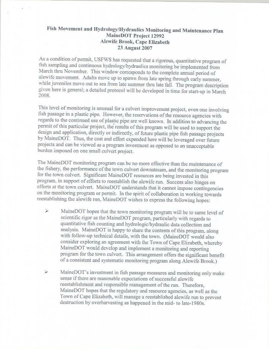
117 98
CHAPTER 4 SPALDING COUNTY, GEORGIA 4.0 CULVERT DESIGN
 SPALDING COUNTY, GEORGIA CHAPTER 4 4.0 CULVERT DESIGN... 4-1 4.1 INTRODUCTION... 4-1 4.2 SYMBOLS AND DEFINITIONS... 4-1 4.3 ENGINEERING DESIGN CRITERIA... 4-2 4.3.1 FREQUENCY FLOOD... 4-2 4.3.2 VELOCITY
Indiana LTAP Road Scholar Core Course #10 Culvert Drainage. Presented by Thomas T. Burke, Jr., PhD, PE Christopher B. Burke Engineering, Ltd.
 Indiana LTAP Road Scholar Core Course #10 Culvert Drainage Presented by Thomas T. Burke, Jr., PhD, PE Christopher B. Burke Engineering, Ltd. Objectives Review culvert shapes, end sections, and materials
APPENDIX B HYDRAULIC DESIGN DATA FOR CULVERTS
 TM 5-820-4/AFM 88-5, Chap 4 APPENDIX B HYDRAULIC DESIGN DATA FOR CULVERTS B-1. General. a. This appendix presents diagrams, charts, coefficients and related information useful in design of culverts. The
Stream Crossings I: Engineering and Design Approaches to Provide Fish Passage at Culvert Slipline Projects in Connecticut
 University of Massachusetts - Amherst ScholarWorks@UMass Amherst International Conference on Engineering and Ecohydrology for Fish Passage International Conference on Engineering and Ecohydrology for Fish
CALIFORNIA SALMONID STREAM HABITAT RESTORATION MANUAL APPENDIX IX-A CULVERT CRITERIA FOR FISH PASSAGE INTRODUCTION
 APPENDIX IX-A STATE OF CALIFORNIA RESOURCES AGENCY DEPARTMENT OF FISH AND GAME CULVERT CRITERIA FOR FISH PASSAGE For habitat protection, ecological connectivity should be a goal of stream-road crossing
CHAPTER 5 CULVERT DESIGN
 CHAPTER 5 CULVERT DESIGN HYDRAULICS OF CULVERTS There are two major types of culvert flow: 1) flow with inlet control, and 2) flow with outlet control. For each type, different factors and formulas are
APPENDIX J HYDROLOGY AND WATER QUALITY
 APPENDIX J HYDROLOGY AND WATER QUALITY J-1 Technical Report on Airport Drainage, Northern Sector Airport and Ordinance Creek Watershed / Preliminary Creek Constructed Natural Channel Culvert J-2 Preliminary
BC Ministry of Forests. March Fish Stream Crossing Guidebook. Forest Practices Code of British Columbia.
 FRST 557 Lecture 7c Bridges and Culverts: Water Velocity and Discharge Lesson Background and Overview: The previous two lessons presented methods for estimating water volume flow at a particular site and
Culvert Design An Overview of the NYS Highway Design Manual Chapter 8
 Seventeenth Statewide Conference on Local Bridges Culvert Design An Overview of the NYS Highway Design Manual Chapter 8 Tuesday, October 25, 2011 Training Session: Culvert Design, Analysis - talk 2 Presented
HY-8 Version 7.2 Build Date January 17, Federal Highway Administration.
 HY-8 Version 7.2 Build Date January 17, 2012 Federal Highway Administration http://www.fhwa.dot.gov/engineering/hydraulics/software/hy8/index.cfm SIMPLE Simple to use Use for simple culverts and bridges
Presented by Fred Halterman, URS Jennie Agerton, URS
 Presented by Fred Halterman, URS Jennie Agerton, URS What is Eco Friendly Culvert Design? Culvert design that: Maintains connectivity for aquatic organism migration Maintains connectivity for gene flow
HEC 26 Aquatic Organism Passage Design Manual Evolution & Application
 HEC 26 Aquatic Organism Passage Design Manual Evolution & Application Sven Leon, P.E., Hydraulics Engineer Federal Highway Administration 2015 Alaska Fish Passage Meeting October 13 14, 2015 VTRC, Juneau,
Culvert Design for Low and High Gradient Streams in the Midwest. Dale Higgins, Hydrologist Chequamegon-Nicolet National Forest
 Culvert Design for Low and High Gradient Streams in the Midwest Dale Higgins, Hydrologist Chequamegon-Nicolet National Forest Overview Culvert Design Considerations Hydraulic Terms Culvert Impacts Low
FINAL REPORT. Yonkers Creek Migration Barrier Removal Project Wonderstump Road Del Norte County. Submitted By:
 FINAL REPORT Yonkers Creek Migration Barrier Removal Project Wonderstump Road Del Norte County Submitted By: Del Norte County Community Development Department Yonkers Creek Migration Barrier Removal Project
The Basics of Culvert and Inlet Design
 PDHonline Course C619 (8 PDH) The Basics of Culvert and Inlet Design Jerry D. Morrow, PE 2013 PDH Online PDH Center 5272 Meadow Estates Drive Fairfax, VA 22030 6658 Phone & Fax: 703 988 0088 www.pdhonline.org
Aquatic Organism Passage at Road-Stream Crossings CHUCK KEEPORTS FOREST HYDROLOGIST ALLEGHENY NATIONAL FOREST WARREN, PENNSYLVANIA
 Aquatic Organism Passage at Road-Stream Crossings CHUCK KEEPORTS FOREST HYDROLOGIST ALLEGHENY NATIONAL FOREST WARREN, PENNSYLVANIA TOPICS COVERED Aquatic Organism Passage (AOP) Benefits of AOP Crossings
Rock Ramp Design Guidelines. David Mooney MS Chris Holmquist-Johnson MS Drew Baird Ph.D. P.E. Kent Collins P.E.
 Rock Ramp Design Guidelines David Mooney MS Chris Holmquist-Johnson MS Drew Baird Ph.D. P.E. Kent Collins P.E. Rock Ramp Design Guidelines OUTLINE Local and System Interactions with Rock Ramps Ramp Geometry
Culvert Hydraulics: Comparison of Current Computer Models
 Brigham Young University BYU ScholarsArchive All Theses and Dissertations 2007-03-13 Culvert Hydraulics: Comparison of Current Computer Models Elizabeth Anne Thiele Brigham Young University - Provo Follow
Discussion on the Selection of the Recommended Fish Passage Design Discharge
 Discussion on the Selection of the Recommended Fish Passage Design Discharge Introduction The provision of fish passage is a requirement for most proposed culvert and bridge installations in Alberta, depending
APPENDIX C VEGETATED EMERGENCY SPILLWAY. VERSION 1.0 March 1, 2011
 APPENDIX C VEGETATED EMERGENCY SPILLWAY VERSION 1.0 March 1, 2011 [NOTE: Could use a better photo more clearly showing the emergency spillway in the context of the dam.] SECTION C-1: DESCRIPTION OF PRACTICE
SELBY CREEK SILVERADO TRAIL CULVERT FISH PASSAGE ASSESSMENT
 SELBY CREEK SILVERADO TRAIL CULVERT FISH PASSAGE ASSESSMENT NAPA COUNTY, CALIFORNIA PREPARED BY NAPA COUNTY RESOURCE CONSERVATION DISTRICT 1303 JEFFERSON ST. SUITE 500B NAPA, CALIFORNIA 94559 WWW.NAPARCD.ORG
Session B5 - Culvert Roughness Elements for Native Utah Fish Passage
 University of Massachusetts - Amherst ScholarWorks@UMass Amherst International Conference on Engineering and Ecohydrology for Fish Passage International Conference on Engineering and Ecohydrology for Fish
General Information for Culvert Design
 Design Manual Chapter 2 - Stormwater 2E - Culvert Design 2E-1 General Information for Culvert Design A. Introduction A culvert is a conduit under an embankment that transports stormwater from one side
Technical Report Culvert A Hydraulic Analysis
 DATE: November 3, 2011 Technical Report Culvert A Hydraulic Analysis TO: FROM: RE: Jim Reiser, P.E. Project Manager Parsons Brinckerhoff, Inc. Kurt Killian, P.E., CFM Parsons Brinckerhoff, Inc. Design
Simulating Streams Through Culverts in Mat-Su, Alaska
 Simulating Streams Through Culverts in Mat-Su, Alaska Project Managers Bill Rice, P.E., USFWS Hydrologist Mary Price, USFWS Fishery Biologist The Team Approach US Fish and Wildlife Service Bill Rice, P.E.,
Lecture 10 : Sewer Appurtenances
 1 P age Module 8 : Sewer Appurtenances Lecture 10 : Sewer Appurtenances 2 P age The structures, which are constructed at suitable intervals along the sewerage system to help its efficient operation and
Culvert Design Basics
 PDHonline Course C287 (4 PDH) Culvert Design Basics Instructor: George E. Thomas, PE 2012 PDH Online PDH Center 5272 Meadow Estates Drive Fairfax, VA 22030-6658 Phone & Fax: 703-988-0088 www.pdhonline.org
Annex E Bridge Pier Protection Plan
 Annex E Bridge Pier Protection Plan Table E1 Bridge Types and Locations Table E2 Flow Conditions For River Sections Figure E1 Bridge Abutment Protection Figure E2 Bridge Pier Protection Figure E3 Central
USING A LABYRINTH WEIR TO INCREASE HYDRAULIC CAPACITY. Dustin Mortensen, P.E. 1 Jake Eckersley, P.E. 1
 USING A LABYRINTH WEIR TO INCREASE HYDRAULIC CAPACITY Dustin Mortensen, P.E. 1 Jake Eckersley, P.E. 1 Plum Creek Floodwater Retarding Structure No. 6 is located in an area of Kyle, Texas, that is currently
(Revised February,2005) CULVERTS, BRIDGES, AND FORDS
 CULVERTS, BRIDGES, AND FORDS") GUIDE TO STREAM CROSSINGS (Revised February,2005) CULVERTS, BRIDGES, AND FORDS Culverts, bridges, and fords are all methods used to cross-streams. Culverts are the most common stream crossing structure.
GUIDE TO STREAM CROSSINGS (Revised February,2005) CULVERTS, BRIDGES, AND FORDS Culverts, bridges, and fords are all methods used to cross-streams. Culverts are the most common stream crossing structure.
Advanced Hydraulics Prof. Dr. Suresh A. Kartha Department of Civil Engineering Indian Institute of Technology, Guwahati
 Advanced Hydraulics Prof. Dr. Suresh A. Kartha Department of Civil Engineering Indian Institute of Technology, Guwahati Module - 4 Hydraulics Jumps Lecture - 4 Features of Hydraulic Jumps (Refer Slide
Five Counties Salmonid Conservation Program - Fish Passage Design Workshop. February 2013
 Program - Aquatic Organisms and Stream Crossings Ecological Connectivity A watershed is a network of channels that drain a common boundary. Channel characteristics formed by interaction of precipitation,
Fish Passage Assessment of Private Stream Crossings on Lower Stonybrook Creek
 Fish Passage Assessment of Private Stream Crossings on Lower Stonybrook Creek Prepared by: Michael Love & Associates In cooperation with: Center for Ecosystem Management and Restoration Funded by: Coastal
Greenup Lock Filling and Emptying System Study
 Fourth LACCEI International Latin American and Caribbean Conference for Engineering and Technology (LACCET 2006) Breaking Frontiers and Barriers in Engineering: Education, Research and Practice 21-23 June
Understanding the Impacts of Culvert Performance on Stream Health
 Understanding the Impacts of Culvert Performance on Stream Health Kristin Thomas Aquatic Ecologist Michigan Trout Unlimited Transportation and the Environment Conference 12/5/2018 Importance of adequately
Advanced Hydraulics Prof. Dr. Suresh A. Kartha Department of Civil Engineering Indian Institute of Technology, Guwahati
 Advanced Hydraulics Prof. Dr. Suresh A. Kartha Department of Civil Engineering Indian Institute of Technology, Guwahati Module - 4 Hydraulic Jumps Lecture - 1 Rapidly Varied Flow- Introduction Welcome
Washington State Fish Passage Barrier Removal Projects. Casey Kramer, PE WSDOT State Hydraulics Engineer
 Washington State Fish Passage Barrier Removal Projects Casey Kramer, PE WSDOT State Hydraulics Engineer 2014 National Hydraulic Engineering Conference Iowa City, IA August 20 th, 2014 WSDOT Fish Passage
Packwood Hydroelectric Project Barrier Analysis December 12, 2006
 Packwood Hydroelectric Project Barrier Analysis December 12, 2006 Study Area Natural barriers to upstream fish passage on Lake Creek at RM 1.03 and RM 1.95 Snyder Creek culvert under the Project tailrace
DESIGN BULLETIN #66/2010
 DESIGN BULLETIN #66/2010 Highway Geometric Design Guide Chapter B, Climbing Lane Warrants for Two Lane Undivided and Four Lane Divided Highways - Revised Summary This Design Bulletin is being issued as
Plan B Dam Breach Assessment
 Plan B Dam Breach Assessment Introduction In support of the Local Sponsor permit applications to the states of Minnesota and North Dakota, a dam breach analysis for the Plan B alignment of the Fargo-Moorhead
Fish Passage Planning and Design
 Fish Passage Planning and Design Culvert Fishway Planning and Design Guidelines Part C Fish Migration Barriers and Fish Passage Options for Road Crossings Ross Kapitzke James Cook University School of
OFFICE OF STRUCTURES MANUAL FOR HYDROLOGIC AND HYDRAULIC DESIGN CHAPTER 13 CULVERTS APRIL 2011
 OFFICE OF STRUCTURES MANUAL FOR HYDROLOGIC AND HYDRAULIC DESIGN CHAPTER 13 CULVERTS APRIL 2011 APRIL 2011 Chapter 13 Culverts Table of Contents Foreword.3 13.1 Introduction.. 4 13.2 Policy 6 13.3 Passage
Experiment (13): Flow channel
: Flow channel") Experiment (13): Flow channel Introduction: An open channel is a duct in which the liquid flows with a free surface exposed to atmospheric pressure. Along the length of the duct, the pressure at the surface
Experiment (13): Flow channel Introduction: An open channel is a duct in which the liquid flows with a free surface exposed to atmospheric pressure. Along the length of the duct, the pressure at the surface
Broadly speaking, there are four different types of structures, each with its own particular function:
 3 The selection of structures 3.1 Introduction In selecting a suitable structure to measure or regulate the flow rate in open channels, all demands that will be made upon the structure should be listed.
TM /AFM 88-5, Chap Underground hydraulic design Inlets UFC - Drainage In Areas Other Than Airfields
 sults of laboratory research concerning soil infiltration through pipe joints and the effectiveness of gasketing tapes for waterproofing joints and seams are available. 3 6. Underground hydraulic design.
FSOC Upstream Fish Passage Guidance Document
 FSOC Upstream Fish Passage Guidance Document STEP 1: Identify species and life stages in need of fish passage STEP 2: Identify fishway options and species applicability STEP 3 Fish passage criteria review
2O-2 Open Channel Flow
 Iowa Stormwater Management Manual O- O- Open Channel Flow A. Introduction The beginning of any channel design or modification is to understand the hydraulics of the stream. The procedures for performing
3. GRADUALLY-VARIED FLOW (GVF) AUTUMN 2018
 AUTUMN 2018") 3. GRADUALLY-VARIED FLOW (GVF) AUTUMN 2018 3.1 Normal Flow vs Gradually-Varied Flow V 2 /2g EGL (energy grade line) Friction slope S f h Geometric slope S 0 In flow the downslope component of weight balances
3. GRADUALLY-VARIED FLOW (GVF) AUTUMN 2018 3.1 Normal Flow vs Gradually-Varied Flow V 2 /2g EGL (energy grade line) Friction slope S f h Geometric slope S 0 In flow the downslope component of weight balances
FISH PASSAGE IMPROVEMENT in California s Watersheds. Assessments & Recommendations by the Fish Passage Forum
 FISH PASSAGE IMPROVEMENT in California s Watersheds Assessments & Recommendations by the Fish Passage Forum FISH PASSAGE IMPROVEMENT in California s Watersheds The mission of the Fish Passage Forum is
Chutes Part 2: Synthetic linings
 s Part 2: Synthetic linings DRAINAGE CONTROL TECHNIQUE Low Gradient Velocity Control Short Term Steep Gradient Channel Lining Medium-Long Term Outlet Control [1] Soil Treatment Permanent [2] [1] s can
Fish Passage Assessment Report Mare Brook Culverts
 Fish Passage Assessment Report Mare Brook Culverts Fish Passage Assessment Component of Mare Brook Watershed Assessment and Community Engagement Project Prepared for: FB Environmental Associates 97A Exchange
Chadbourne Dam Repair and Fish Barrier
 Chadbourne Dam Repair and Fish Barrier Final Report for the Western Native Trout Initiative Prepared by: Carol Endicott Yellowstone Cutthroat Trout Conservation Biologist Montana Fish, Wildlife & Parks
TOP:001.3 U.S. Fish and Wildlife Service TECHNICAL OPERATING PROCEDURE
 TOP:001.3 March 12, 2015 U.S. Fish and Wildlife Service Marquette Biological Station 3090 Wright Street Marquette, Michigan 49855 U.S.A. and U.S. Fish and Wildlife Service Ludington Biological Station
Trout Unlimited Comments on the Scope of Environmental Impact Statement for the Constitution Pipeline Project, Docket No. PF12-9
 October 9, 2012 Kimberly D. Bose, Secretary Federal Energy Regulatory Commission 888 First Street, NE, Room 1A Washington, DC 20426 RE: Trout Unlimited Comments on the Scope of Environmental Impact Statement
City of Elizabeth City Neighborhood Traffic Calming Policy and Guidelines
 City of Elizabeth City Neighborhood Traffic Calming Policy and Guidelines I. Purpose: The City of Elizabeth City is committed to ensure the overall safety and livability of residential neighborhoods. One
Fish Passage Culvert Assessment for Cahilty Creek Watershed FIA Project #
 Fish Passage Culvert Assessment for Cahilty Creek Watershed FIA Project # 4602004 Prepared for Weyerhaeuser Company Ltd. Jason Ladyman R.P.F. 1550 Mission Flats Road PO Box 40 Kamloops BC V2C 5K3 Prepared
An Analysis of Reducing Pedestrian-Walking-Speed Impacts on Intersection Traffic MOEs
 An Analysis of Reducing Pedestrian-Walking-Speed Impacts on Intersection Traffic MOEs A Thesis Proposal By XIAOHAN LI Submitted to the Office of Graduate Studies of Texas A&M University In partial fulfillment
Union Pacific Railroad
 Input Questions: 404/401 Pre Application Meeting, December 18, 2013, Portland, Oregon 1. What is the project purpose and need? The purpose of the project is to improve the efficiency and average velocity
APPENDIX A STRUCTURE DESCRIPTIONS AND RATING CURVES
 3 4 5 6 7 8 9 0 3 APPENDIX A STRUCTURE DESCRIPTIONS AND RATING CURVES Kissimmee River Vol December 005 Version Draft 4 3 4 5 6 7 8 9 0 3 4 5 6 7 8 9 0 3 4 5 6 7 8 9 30 3 3 33 34 35 36 37 38 39 40 4 4 43
Drilling Efficiency Utilizing Coriolis Flow Technology
 Session 12: Drilling Efficiency Utilizing Coriolis Flow Technology Clement Cabanayan Emerson Process Management Abstract Continuous, accurate and reliable measurement of drilling fluid volumes and densities
Chapter 11. Culverts and Bridges Design Checklist for Culvert Design
 Yes No N/A Design Requirements I. GENERAL DESIGN GUIDELINES Chapter 11. Culverts and Bridges A. Culvert design is in accordance with the Culverts chapter of Volume 2 of the UDFCD Manual for additional
Colusa Basin Drain Watershed Fish Stranding Tour Concept Paper Mike Hendrick and Brycen Swart NMFS
 Colusa Basin Drain Watershed Fish Stranding Tour Concept Paper Mike Hendrick and Brycen Swart NMFS On May 31, 2013 representatives from CDFW, USFWS, and NMFS went on a field tour to look at locations in
OFFICE OF STRUCTURES MANUAL FOR HYDROLOGIC AND HYDRAULIC DESIGN CHAPTER 11 APPENDIX B TIDEROUT 2 USERS MANUAL
 OFFICE OF STRUCTURES MANUAL FOR HYDROLOGIC AND HYDRAULIC DESIGN CHAPTER 11 APPENDIX B TIDEROUT 2 USERS MANUAL APRIL 2011 APRIL 2011 Page 1 Preface TIDEROUT 2, Build 1.22 dated June 29, 2006 is the current
Field Design, Construction and inspection of ADA compliant Curb ramps. Mike Anderson City of Lee s Summit Construction Manager (816)
") Field Design, Construction and inspection of ADA compliant Curb ramps Mike Anderson City of Lee s Summit Construction Manager (816)969-1800 Today s Agenda Definitions & Acronyms Access Board vs. PROWAAC
Field Design, Construction and inspection of ADA compliant Curb ramps Mike Anderson City of Lee s Summit Construction Manager (816)969-1800 Today s Agenda Definitions & Acronyms Access Board vs. PROWAAC
ADDENDA B Hydrologic and Hydraulic (H&H) Study Guidance 2019
 Study Guidance 2019") 09/25/2018 DRAFT FEMA Region I PA H&H Study ADDENDA B Hydrologic and Hydraulic (H&H) Study Guidance 2019 Region I Federal Emergency Management Agency (FEMA) Public Assistance Hydrologic and Hydraulic (H&H)
09/25/2018 DRAFT FEMA Region I PA H&H Study ADDENDA B Hydrologic and Hydraulic (H&H) Study Guidance 2019 Region I Federal Emergency Management Agency (FEMA) Public Assistance Hydrologic and Hydraulic (H&H)
Sediment Basin 7E-12. Design Manual Chapter 7 - Erosion and Sediment Control 7E - Design Information for ESC Measures BENEFITS.
 7E-12 Design Manual Chapter 7 - Erosion and Sediment Control 7E - Design Information for ESC Measures Sediment Basin BENEFITS Flow Control Erosion Control Sediment Control Runoff Reduction Flow Diversion
Effect of Fluid Density and Temperature on Discharge Coefficient of Ogee Spillways Using Physical Models
 RESEARCH ARTICLE Effect of Fluid Density and Temperature on Discharge Coefficient of Ogee Spillways Using Physical Models M. SREENIVASULU REDDY 1 DR Y. RAMALINGA REDDY 2 Assistant Professor, School of
Hydraulic and Economic Analysis of Real Time Control
 Hydraulic and Economic Analysis of Real Time Control Tom Walski 1, Enrico Creaco 2 1 Bentley Systems, Incorporated, 3 Brian s Place, Nanticoke, PA, USA 2 Dipartimento di Ingegneria Civile ed Architettura,
Access Management Standards
 Access Management Standards Section 1: Application of Access Standards This chapter describes the Department's access management standards for access connections on the county roadway system. The standards
Ontario Ministry of Transportation (MTO) Restoring Fish Passage to a Tributary of the Saugeen River
 Restoring Fish Passage to a Tributary of the Saugeen River") Ontario Ministry of Transportation (MTO) Restoring Fish Passage to a Tributary of the Saugeen River 2017 Transportation Association of Canada Environmental Achievement Award Nomination Submission Prepared
Ontario Ministry of Transportation (MTO) Restoring Fish Passage to a Tributary of the Saugeen River 2017 Transportation Association of Canada Environmental Achievement Award Nomination Submission Prepared
Request Number IR1-12: Flow Passage. Information Request
 Request Number IR1-12: Flow Passage Information Request Provide additional information about the 100 metre flow passage channel scenario between the Westshore Terminals and the proposed Project terminal
Information for File # SEW
 Information for File #2014-02744-SEW Applicant: Minnesota Department of Transportation (MnDOT), District 3; c/o Mr. Robert Nibbe Corps Contact: Sarah Wingert, U.S. Army Corps of Engineers, 180 5 th Street
CSO/STORMWATER MANAGEMENT. HYDROVEX VHV / SVHV Vertical Vortex Flow Regulator
 CSO/STORMWATER MANAGEMENT HYDROVEX VHV / SVHV Vertical Vortex Flow Regulator HYDROVEX VHV / SVHV VERTICAL VORTEX FLOW REGULATOR APPLICATIONS One of the major problems of urban wet weather flow management
Low Gradient Velocity Control Short Term Steep Gradient Channel Lining Medium-Long Term Outlet Control Soil Treatment Permanent [1]
![Low Gradient Velocity Control Short Term Steep Gradient Channel Lining Medium-Long Term Outlet Control Soil Treatment Permanent [1]](/thumbs/80/80811988.jpg "Low Gradient Velocity Control Short Term Steep Gradient Channel Lining Medium-Long Term Outlet Control Soil Treatment Permanent [1]") Check Dams DRAINAGE CONTROL TECHNIQUE Low Gradient Velocity Control Short Term Steep Gradient Channel Lining Medium-Long Term Outlet Control Soil Treatment Permanent [1] [1] Though not generally considered
Check Dams DRAINAGE CONTROL TECHNIQUE Low Gradient Velocity Control Short Term Steep Gradient Channel Lining Medium-Long Term Outlet Control Soil Treatment Permanent [1] [1] Though not generally considered
Dry Hydrants. The installation of a non-pressurized pipe system into local water sources provides a ready means of supplying water to fire engines.
 Dry Hydrants What is a Dry Hydrant? A dry hydrant is a non-pressurized pipe system permanently installed in existing lakes, ponds and streams that provides a suction supply of water to a fire department
H8 Signs, Supports and Poles
 Alberta Infrastructure and Transportation Roadside Design Guide November 2007 H8 Signs, Supports and Poles H8.1 Introduction This section identifies the appropriate roadside safety treatment for signs,
Assessment of Baseline Geomorphic Features at. Proposed Stream Crossings On The Proposed County Road 595. Marquette County, Michigan
 Assessment of Baseline Geomorphic Features at Proposed Stream Crossings On The Proposed County Road 595 Marquette County, Michigan Prepared for: Kennecott Eagle Minerals Company Marquette, Michigan Prepared
WMS 8.4 Tutorial Hydraulics and Floodplain Modeling HY-8 Modeling Wizard Learn how to model a culvert using HY-8 and WMS
 v. 8.4 WMS 8.4 Tutorial Hydraulics and Floodplain Modeling HY-8 Modeling Wizard Learn how to model a culvert using HY-8 and WMS Objectives Define a conceptual schematic of the roadway, invert, and downstream
Guidance Note. Hydropower Guidance Note: HGN 8 Fish Passage. When do you need to install a fish pass?
 Guidance Note Hydropower Guidance Note: This guidance note is not intended as a statement of law. It should be read in combination with, and in the context of, the relevant enactments and EU obligations.
Designing Labyrinth Spillways for Less than Ideal Conditions Real World Application of Laboratory Design Methods
 Designing Labyrinth Spillways for Less than Ideal Conditions Real World Application of Laboratory Design Methods Gregory Richards, P.E., CFM, Gannett Fleming, Inc. Blake Tullis, Ph.D., Utah Water Research
PIG MOTION AND DYNAMICS IN COMPLEX GAS NETWORKS. Dr Aidan O Donoghue, Pipeline Research Limited, Glasgow
 PIG MOTION AND DYNAMICS IN COMPLEX GAS NETWORKS Dr Aidan O Donoghue, Pipeline Research Limited, Glasgow A model to examine pigging and inspection of gas networks with multiple pipelines, connections and
Suitable Applications Check dams may be appropriate in the following situations: To promote sedimentation behind the dam.
 Categories EC Erosion Control SE Sediment Control TC Tracking Control WE Wind Erosion Control Non-Stormwater NS Management Control Waste Management and WM Materials Pollution Control Legend: Primary Category
JONESBORO HIGHWAY 63 HIGHWAY 18 CONNECTOR STUDY
 JONESBORO HIGHWAY 63 HIGHWAY 18 CONNECTOR STUDY Craighead County May 2007 JONESBORO HIGHWAY 63 HIGHWAY 18 CONNECTOR STUDY Craighead County May 2007 Prepared by Planning and Research Division Arkansas State
Transition Submergence and Hysteresis Effects in Three-Foot Cutthroat Flumes
 Transition Submergence and Hysteresis Effects in Three-Foot Cutthroat Flumes Why Measure Water for Irrigation? (You had to ask.) Improve: Accuracy Convenience Economics Water Measurement Manual (Door Prize)
Driveway Design Criteria
 Design Manual Chapter 5 - Roadway Design 5L - Access Management 5L-4 Driveway Design Criteria A. General For efficient and safe operations, access drives and minor public street intersections can be improved
Exercise (3): Open Channel Flow Rapidly Varied Flow
: Open Channel Flow Rapidly Varied Flow") Exercise (3): Open Channel Flow Rapidly Varied Flow 1) A hydraulic jump exists in a trapezoidal channel having a bed width of 7 m and side slope of 1:1. The flowing discharge is 25 m 3 /sec. Construct
Exercise (3): Open Channel Flow Rapidly Varied Flow 1) A hydraulic jump exists in a trapezoidal channel having a bed width of 7 m and side slope of 1:1. The flowing discharge is 25 m 3 /sec. Construct
FISHERIES BLUE MOUNTAINS ADAPTATION PARTNERSHIP
 FISHERIES A warming climate, by itself, substantially affects the hydrology of watersheds in the Blue Mountains. Among the key hydrologic changes projected under all scenarios for the 2040s and beyond
Follow this and additional works at:
 Lehigh University Lehigh Preserve Fritz Laboratory Reports Civil and Environmental Engineering 1987 Model study. Of a culvert safety grating - south 4th and brookdale streets, ALLENTOWN, PA for the Allentown
Evaluating the Design Safety of Highway Structural Supports
 Evaluating the Design Safety of Highway Structural Supports by Fouad H. Fouad and Elizabeth A. Calvert Department of Civil and Environmental Engineering The University of Alabama at Birmingham Birmingham,
Evaluating Surge Potential in CSO Tunnels
 14 Evaluating Surge Potential in CSO Tunnels Karen E. Ridgway Tunnels are being proposed to control combined sewer overflow (CSO) in numerous cities in the United States and Canada. The tunnels are intended
Hydraulic Modeling of Stream Enhancement Methods
 Hydraulic Modeling of Stream Enhancement Methods Matthew J. Curry John J. Levitsky Abstract Development within watersheds increases the amounts of runoff causing stream erosion and degradation of stream
FLOW MEASUREMENT (SEMI-SUBMERGIBLE OBJECT METHOD)
") Page 83 of 232 OKLAHOMA CONSERVATION COMMISSION WATER QUALITY DIVISION STANDARD OPERATING PROCEDURE FLOW MEASUREMENT (SEMI-SUBMERGIBLE OBJECT METHOD) Page 84 of 232 1.0 PROCEDURAL SECTION 1.1 Scope and
Page 83 of 232 OKLAHOMA CONSERVATION COMMISSION WATER QUALITY DIVISION STANDARD OPERATING PROCEDURE FLOW MEASUREMENT (SEMI-SUBMERGIBLE OBJECT METHOD) Page 84 of 232 1.0 PROCEDURAL SECTION 1.1 Scope and
EXAMPLES (OPEN-CHANNEL FLOW) AUTUMN 2018
 AUTUMN 2018") EXAMPLES (OPEN-CHANNEL FLOW) AUTUMN 2018 Normal and Critical Depths Q1. If the discharge in a channel of width 5 m is 20 m 3 s 1 and Manning s n is 0.02 m 1/3 s, find: (a) the normal depth and Froude number
EXAMPLES (OPEN-CHANNEL FLOW) AUTUMN 2018 Normal and Critical Depths Q1. If the discharge in a channel of width 5 m is 20 m 3 s 1 and Manning s n is 0.02 m 1/3 s, find: (a) the normal depth and Froude number
PHASE 1 WIND STUDIES REPORT
 PHASE 1 WIND STUDIES REPORT ENVIRONMENTAL STUDIES AND PRELIMINARY DESIGN FOR A SUICIDE DETERRENT SYSTEM Contract 2006-B-17 24 MAY 2007 Golden Gate Bridge Highway and Transportation District Introduction
Project Report for Marsh Creek and Albion River Instream Fish Barrier Removal Flynn Creek Road, CR 135, M.P. 8.1 and 8.3
 Project Report for Marsh Creek and Albion River Instream Fish Barrier Removal Flynn Creek Road, CR 135, M.P. 8.1 and 8.3 Project Title: Marsh Creek and Albion River Instream Fish Barrier Removal, Flynn
3-13 UFC - GENERAL PROVISIONS AND GEOMETRIC DESIGN FOR ROADS, STREETS, WALKS, AND OPEN
 maintenance, and erosion. Stability is required to maintain the integrity of the pavement structure, and a slope stability analysis should be conducted for cuts and fills greater than 15 feet. For lower
Subject: Developed fish ladder alternatives for Pastori Avenue at San Anselmo Creek
 Page 1 of 18 SENT VIA EMAIL Sandra Guldman Friends of Corte Madera Creek Watershed Box 415 Larkspur, CA 94977 Subject: Developed fish ladder alternatives for Pastori Avenue at San Anselmo Creek Dear Sandra,
Ermenek Dam and HEPP: Spillway Test & 3D Numeric-Hydraulic Analysis of Jet Collision
 Ermenek Dam and HEPP: Spillway Test & 3D Numeric-Hydraulic Analysis of Jet Collision J.Linortner & R.Faber Pöyry Energy GmbH, Turkey-Austria E.Üzücek & T.Dinçergök General Directorate of State Hydraulic
ANSWERS TO QUESTIONS IN THE NOTES AUTUMN 2018
 ANSWERS TO QUESTIONS IN THE NOTES AUTUMN 2018 Section 1.2 Example. The discharge in a channel with bottom width 3 m is 12 m 3 s 1. If Manning s n is 0.013 m -1/3 s and the streamwise slope is 1 in 200,
STRUCTURE S-65 PURPOSE SPILLWAY OPERATION
 STRUCTURE S-65 This structure is a reinforced concrete, gated spillway with discharge controlled by three cable operated, vertical lift gates, and a reinforced concrete lock structure with two pairs of