APPENDIX A STRUCTURE DESCRIPTIONS AND RATING CURVES
|
|
|
- Stanley Hubbard
- 5 years ago
- Views:
Transcription
1 APPENDIX A STRUCTURE DESCRIPTIONS AND RATING CURVES Kissimmee River Vol December 005 Version Draft 4
2 Structure 57 (S-57) Structure 58 (S-58) Structure 59 (S-59) Structure 60 (S-60) Structure 6 (S-6) Structure 6 (S-6) Structure 63 (S-63) Structure 63A (S-63A) Structure 65 (S-65) Structure 65A (S-65A) Structure 65B (S-65B) Structure 65C (S-65C) Structure 65D (S-65D) Structure 65E (S-65E) Structure 68 (S-68) Structure 70 (S-70) Structure 7 (S-7) Structure 7 (S-7) Structure 75 (S-75) Structure 8 (S-8) Structure 83 (S-83) Structure 84 (S-84) APPENDIX A PROJECT STRUCTURE DESCRIPTIONS TABLE OF CONTENTS Tables Page No. A-S57- A-S58- A-S59- A-S60- A-S6- A-S6- A-S63- A-S63A- A-S65- A-S65A- A-S65B- A-S65C- A-S65D- A-S65E- A-S68- A-S70- A-S7- A-S7- A-S75- A-S8- A-S83- A-S84- Page No. Structure 57 Hydraulic Design Data A-S57- Structure 58 Hydraulic Design Data A-S58- Structure 59 Hydraulic Design Data A-S59- Structure 60 Hydraulic Design Data A-S60- Structure 6 Hydraulic Design Data A-S6- Structure 6 Hydraulic Design Data A-S6- Structure 63 Hydraulic Design Data A-S63- Structure 63A Hydraulic Design Data A-S63A- Structure 65 Hydraulic Design Data A-S65- Structure 65A Hydraulic Design Data A-S65A- Structure 65B Hydraulic Design Data A-S65B- Kissimmee River Vol A-i December 005 Version Draft 4
3 Tables (Continued) Page No. 3 Structure 65C Hydraulic Design Data A-S65C- 4 Structure 65D Hydraulic Design Data A-S65D- 5 Structure 65E Hydraulic Design Data A-S65E- 6 Structure 68 Hydraulic Design Data A-S68-7 Structure 70 Hydraulic Design Data A-S70-8 Structure 7 Hydraulic Design Data A-S7-9 Structure 7 Hydraulic Design Data A-S7-0 Structure 75 Hydraulic Design Data A-S75- Structure 8 Hydraulic Design Data A-S8- Structure 83 Hydraulic Design Data A-S83-3 Structure 84 Hydraulic Design Data A-S Rating Curves 6 7 Page No. 8 Structure 57 Controlled Flow A-S Uncontrolled Flow A-S Structure 58 Discharge Rating Curve A-S58-3 Structure 59 Submerged Controlled Flow A-S59-4 Submerged Uncontrolled Flow A-S MAGOs A-S Structure 60 Controlled Flow A-S Submerged Controlled Flow A-S Uncontrolled Flow A-S MAGO Curve A-S Structure 6 Submerged Controlled Flow A-S6-4 9 Submerged Uncontrolled Flow A-S MAGO Curve A-S6-6 3 Structure 6 Controlled Flow A-S6-4 3 Submerged Controlled Flow A-S Uncontrolled Flow A-S MAGO Curve A-S Structure 63 Controlled Discharge A-S Submerged Controlled Flow A-S Uncontrolled Flow A-S MAGO Curve A-S Structure 63A Controlled Flow A-S63A-4 40 Submerged Controlled Flow A-S63A-5 4 Uncontrolled Flow A-S63A-6 4 MAGO Curve A-S63A-7 Kissimmee River Vol A-ii December 005 Version Draft 4
4 Rating Curves (Continued) Structure 65 Controlled Flow A-S65-4 Rating Curve for Submerged Conditions A-S65-5 Uncontrolled Flow A-S65-6 MAGO Curve A-S65-7 Structure 65A Controlled Flow A-S65A-4 Uncontrolled Flow A-S65A-5 Submerged Controlled Flow A-S65A-6 MAGOs A-S65A-7 Structure 65B Controlled Flow A-S65B-5 Uncontrolled Flow A-S65B-6 Submerged Controlled Flow A-S65B-7 MAGOs A-S65B-8 West Tieback Levee Culvert (S-65BX-) A-S65B-9 Structure 65C Controlled Flow A-S65C-4 Uncontrolled A-S65C-5 Submerged Controlled Flow A-S65C-6 MAGOs A-S65C-7 Structure 65D Controlled Flow A-S65D-4 Uncontrolled Flow A-S65D-5 Submerged Controlled Flow A-S65D-6 MAGOs A-S65D-7 Structure 65E Free Controlled Flow - Six Gates A-S65E-4 Free Controlled Flow - One Gate A-S65E-5 Uncontrolled Flow A-S65E-6 Submerged Controlled Flow A-S65E-7 MAGOCurve A-S65E-8 Structure 68 Free Controlled Flow A-S68-4 Submerged Uncontrolled Flow A-S68-5 Submerged Controlled Flow A-S68-6 MAGOCurves A-S68-7 Structure 70 MAGOCurve A-S70-4 Structure 7 Free Controlled Flow A-S7-4 Submerged Uncontrolled Flow A-S7-5 Submerged Controlled Flow A-S7-6 MAGOs, Specific Cases A-S7-7 MAGOs, General Case A-S7-8 Structure 7 Submerged Controlled Flow A-S7-4 Submerged Uncontrolled Flow A-S7-5 MAGOs, Specific Cases A-S7-6 MAGOs, General Case A-S7-7 Kissimmee River Vol A-iii December 005 Version Draft 4
5 Rating Curves (Continued) Structure 75 MAGOs A-S75-4 Structure 8 Submerged Controlled Flow A-S8-4 Free Controlled Flow A-S8-5 Uncontrolled Flow A-S8-6 MAGOs A-S8-7 Structure 83 MAGOs A-S83-4 Structure 84 Submerged Controlled Flow A-S84-4 Free Controlled Flow A-S84-5 Uncontrolled Flow A-S84-6 MAGOs A-S84-7 Kissimmee River Vol A-iv December 005 Version Draft 4
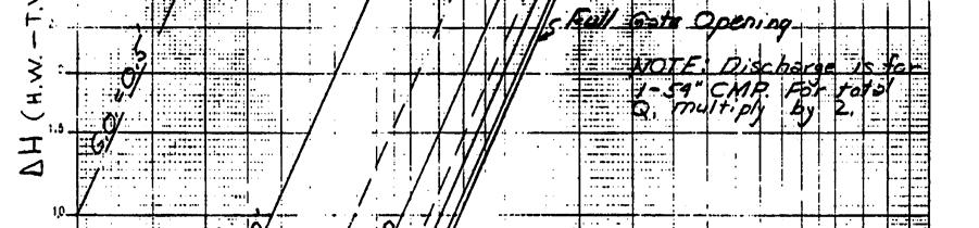
6 S-57 STRUCTURE 57 Location S-57 is located in C-30, connecting Lakes Myrtle and Mary Jane, about 6,00 feet downstream from Lake Myrtle. Description S-57 is a double-barreled corrugated metal pipe (CMP) culvert, with discharge controlled by stem operated vertical lift gates. Operation of the gates is manually controlled in accordance with the seasonal operational criteria. Purpose The culvert structure is used to maintain scheduled stages in Lakes Myrtle, Preston, and Joel upstream from the structure; passes up to 30 percent of the standard project flood (SPF); and passes sufficient discharge during low-flow periods to satisfy irrigation demands downstream. Operation The culvert structure normally maintains seasonal water-control stages of from 60.0 to 6.0 ft., NGVD upstream from the structure, as shown on the regulation schedule. When the lake stage rises above schedule and above normal inflows are anticipated, releases up to design capacity of 70 cfs can be made. The gates should be opened gradually to allow tailwater stages to rise before large releases are made. During low-water periods, minimum releases will be made to satisfy irrigation demands and maintain navigation downstream. The discharge rating curve is found on Figure A-S57-. Hydraulic Design Data is found on page A-S57-. Maximum Head To meet structural and stability requirements, the maximum allowable hydrostatic head on the structure should not be allowed to exceed. ft., NGVD with a headwater elevation of 59.0 ft., NGVD, and a tailwater elevation of 56.8 ft., NGVD. Kissimmee River Vol A-S57- December 005 Version Draft 4
7 STRUCTURE 57 HYDRAULIC DESIGN DATA Type of Structure Culvert Location Canal C-30 Station Discharge (cfs) Design 70 Headwater Elevation Design 6.8 SPF 66.8 Optimum 60.0 to 6.0 Minimum 59.0 Tailwater Elevation Design 6.6 SPF 66.7 Optimum 59.0 to 6.0 Minimum 56.8 Culvert Number Size 54 in CMP Invert Elevation 5.5 Type of Control Slidegate Approximate Ground Elevation at Structure Protection Elevation 68.8 Notes: All elevations refer to feet, NGVD. Kissimmee River Vol A-S57- December 005 Version Draft 4
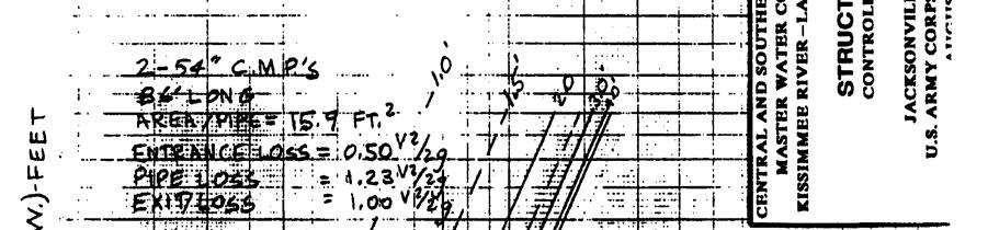
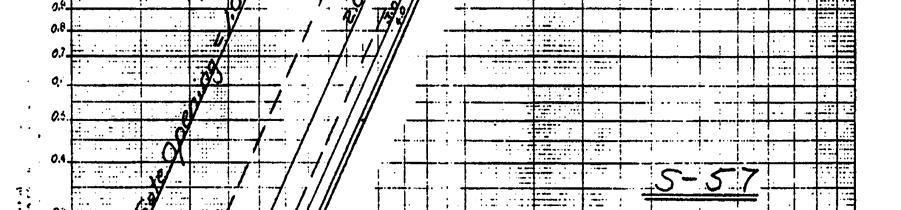
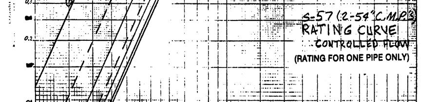
8 S-57 CONTROLLED FLOW Kissimmee River Vol A-S57- December 005 Version Draft 4
9 S-57 UNCONTROLLED FLOW Kissimmee River Vol A-S57-3 December 005 Version Draft 4
10 S-58 STRUCTURE 58 Location S-58 is located in C-3 which connects Lakes Trout and Joel, about 3,700 feet downstream from Trout Lake. Description S-58 is a double barreled CMP culvert with discharge controlled by stem operated vertical lift gates. Operation of the gates is manually controlled in accordance with the seasonal operational criteria. Purpose The culvert structure maintains water-control stages in C-3 and Lakes Alligator, Lizzie, Coon, Center, and Trout; passes up to 30 percent of the SPF; and passes sufficient discharge during low-flow periods to meet irrigation demands downstream. Operation During floods the culvert structure is used, together with S-60, to assist in regulating and maintaining water levels of from 6.0 ft. to 64.0 ft., NGVD, in the lake upstream form the structure, as shown on the regulation schedule. The design capacity of the structure is 60 cfs. The gates should be opened gradually to allow tailwater stages to rise before large releases are made. During low-water periods, minimum releases will be made to satisfy irrigation demands and maintain navigation downstream. Discharge-Rating Curves are found on Figure A-S58-. Hydraulic Design Data is found on page A-S58-. Maximum Head To meet structural and stability requirements, the maximum allowable hydrostatic head on the structure should not be allowed to exceed.0 ft., NGVD with a headwater elevation of 64.0 ft., NGVD and a tailwater elevation of 6.0 ft., NGVD. Kissimmee River Vol A-S58- December 005 Version Draft 4
11 STRUCTURE 58 HYDRAULIC DESIGN DATA Type of Structure Culvert Location Canal C-3 Station Discharge (cfs) Design 60 Headwater Elevation Design 64.8 SPF 67.4 Critical - Optimum 6.0 to 64.0 Minimum 60.4 Tailwater Elevation Design 63.0 SPF 66.7 Critical - Optimum 60.0 to 6.0 Minimum 59.0 Culvert Number Size 54 in CMP Invert Elevation 54.5 Type of Control Slidegate Riprap Upstream Channel Length (ft.) 0.0 Protection Elev Downstream Channel Length (ft.) 0.0 Protection Elev Protection Elevation 69.4 Notes: All elevations refer to feet, NGVD. Kissimmee River Vol A-S58- December 005 Version Draft 4

12 S-58 DISCHARGE RATING CURVE Kissimmee River Vol A-S58- December 005 Version Draft 4
13 S-59 STRUCTURE 59 (S-59) Location S-59 is located in C-3 between East Lake Tohopekaliga and Lake Tohopekaliga at the outlet of East Lake Tohopekaliga. Description S-59 is a reinforced concrete, gated spillway with discharge controlled by a vertical lift gate. Operation of the gate is manually controlled in accordance with seasonal operational criteria. Purpose S-59 is the outlet structure for East Lake Tohopekaliga. The spillway structure normally maintains desirable water-control stages in the lake upstream from the structure; passes up to 30 percent of the SPF without exceeding desirable stages; restricts discharges during floods to that which will not cause damaging velocities or stages downstream; and passes sufficient discharge during low-flow periods to maintain stages and satisfy irrigation demands. Operation The gate in the spillway should be operated to permit water levels in East Lake Tohopekaliga to fluctuate seasonally between 55 to 58 ft., NGVD, as shown on the regulation schedule. When the lake is within one-half foot of the schedule, forecasts should be made and releases initiated to return the lake to schedule within 5 days. When the lake stage is considerably above schedule and large inflows are anticipated, releases up to design capacity of 80 cfs can be made. To insure the safety of the structure, gate settings should never exceed the limits shown on the MAGO curves and be checked frequently to insure that design capacity of the structure or C-3 downstream is not exceeded. The gate should be opened gradually to allow tailwater stages to rise before large releases are made. During low-water periods, minimum release will be made to satisfy irrigation demands and maintain navigation downstream. Downstream Weir Downstream of S-59 a sheetpile weir was constructed to influence the tailwater of the structure. The crest of the weir is elevation ft., NGVD Maximum Head To meet structural and stability requirements, the maximum differential hydrostatic head on the structure should not be allowed to exceed 8 ft., NGVD when the headwater is below 6.8 ft., NGVD. If the headwater should ever exceed 6.8 ft., NGVD, the allowable differential head will be reduced. Kissimmee River Vol A-S59- December 005 Version Draft 4
14 STRUCTURE 59 HYDRAULIC DESIGN DATA Type of Structure Spillway Location Canal C-3 Station Discharge (cfs) Design 590 to 80 SPF 300 Headwater Elevation Design 55.8 to 57.5 SPF 6.8 Critical - Optimum 55.0 to 58.0 Minimum 53. Tailwater Elevation Design 55.3 to 56.9 SPF 6. Critical - Optimum 53.0 to 55.0 Minimum 50.0 Crest Shape Trapezoidal Elevation 49. Net Length (ft.) 8.0 Gates Number Width X Height (ft.) 8.9 X 8.0 Clearance Elevation 58.0 Stilling Basin Apron Elevation 48. Apron Length 0.0 X 8.0 End Still Elevation 48.6 Training Wall Elevation 56.9 Channel Section Side Slopes (vert. On horiz.) on Upstream Bottom Width & Elev Downstream Bottom Width & Elev Kissimmee River Vol A-S59- December 005 Version Draft 4
15 HYDRAULIC DESIGN DATA (CONTINUED) Riprap Upstream Channel Length (ft.) 0.0 Protection Elev. 6.0 Downstream Channel Length (ft.) 40.0 Protection Elev Approximate Ground Elevation at Structure 6+ Protection Elevation 64.8 Notes: All elevations refer to feet, NGVD. Kissimmee River Vol A-S59-3 December 005 Version Draft 4

16 S-59 SUBMERGED CONTROLLED FLOW Kissimmee River Vol A-S59-4 December 005 Version Draft 4


17 S-59 SUBMERGED UNCONTROLLED FLOW Kissimmee River Vol A-S59-5 December 005 Version Draft 4


18 S-59 MAXIMUM ALLOWABLE GATE OPENINGS Kissimmee River Vol A-S59-6 December 005 Version Draft 4
19 S-60 STRUCTURE 60 Location S-60 is located in C-33 between Lakes Alligator and Gentry about,500 feet upstream from S.R. and 3,700 feet downstream from Alligator Lake. Description S-60 is a reinforced concrete, gated spillway with discharge controlled by a stem operated, vertical lift gate. Operation of the gate is manually controlled in accordance with seasonal operational criteria. Purpose The spillway structure maintains desirable water-control stages in C-33 and Alligator Lake; passes up to 30 percent of the SPF without exceeding desirable stages; restricts discharge during floods to that which will not cause damaging velocities or stages downstream; and passes sufficient discharge during low-flow periods to maintain stages and satisfy irrigation demands downstream. Operation The spillway structure normally maintains a seasonal desirable water-control stage of 6.0 to 64.0 ft., NGVD, upstream from the structure, as shown on the regulation schedule. S-60 and S-58 both discharge from Alligator Lake, consequently discharges from both structures must be considered is establishing release schedules. When the lake is within one-half foot of schedule, forecasts should be made and releases initiated to return the lake to schedule within 5 days. When the lake stage is considerably above schedule and inflows are anticipated, releases up to design capacity of 450 cfs can be made. However, to insure the safety of the structure, gate settings should never exceed the limits shown on the MAGO Curves, and should be checked at frequent intervals to insure that the design capacity of the structure is not exceeded. The gate should be opened gradually to allow the tailwater to rise before large releases are made. During low-water periods, minimum releases will be made to satisfy irrigation demands and maintain navigation downstream. Maximum Head The maximum water level differential should not exceed seven feet with the headwater not exceeding elevation 68.0 ft., NGVD. Kissimmee River Vol A-S60- December 005 Version Draft 4
20 STRUCTURE 60 HYDRAULIC DESIGN DATA Type of Structure Spillway Location Canal C-33 Station Discharge (cfs) Design 450 SPF Critical - Headwater Elevation Design 6.3 to 64. SPF 67.4 Critical - Optimum 6.0 to 64.0 Minimum 66.4 Tailwater Elevation Design 6.7 to 63.3 SPF 66.4 Critical - Optimum 60.0 to 6.0 Minimum 57.6 Crest Shape Ogee Elevation 55.0 Net Length (ft.).0 Gates Number Width X Height (ft.) 9. X.8 Clearance Elevation 65.0 Stilling Basin Apron Elevation 5.0 Apron Length 30.0 End Still Elevation 5.0 Training Wall Elevation 63.5 Kissimmee River Vol A-S60- December 005 Version Draft 4
21 STRUCTURE 60 HYDRAULIC DESIGN DATA (CONTINUED) Channel Section Side Slopes (vert. On horiz.) on Upstream Bottom Width & Elev. Downstream Bottom Width & Elev Riprap Upstream Channel Length (ft.) 35.0 Protection Elev Downstream Channel Length (ft.) 50.0 Protection Elev Approximate Ground Elevation at Structure 6+ Protection Elevation 7.0 Notes: All elevations refer to feet, NGVD. Kissimmee River Vol A-S60-3 December 005 Version Draft 4

22 S-60 CONTROLLED FLOW Kissimmee River Vol A-S60-4 December 005 Version Draft 4

23 S-60 SUBMERGED CONTROLLED FLOW Kissimmee River Vol A-S60-5 December 005 Version Draft


24 S-60 UNCONTROLLED FLOW Kissimmee River Vol A-S60-6 December 005 Version Draft 4


25 S-60 MAXIMUM ALLOWABLE GATE OPENING CURVES Kissimmee River Vol A-S60-7 December 005 Version Draft 4
STRUCTURE 65-B PURPOSE SPILLWAY OPERATION
 STRUCTURE 65-B This structure is a reinforced concrete, gated spillway with discharge controlled by three cable operated vertical lift gates and a reinforced concrete lock structure with two pairs of sector
STRUCTURE S-65 PURPOSE SPILLWAY OPERATION
 STRUCTURE S-65 This structure is a reinforced concrete, gated spillway with discharge controlled by three cable operated, vertical lift gates, and a reinforced concrete lock structure with two pairs of
APPENDIX A STRUCTURE DESCRIPTIONS AND RATING CURVES. Lake Okeechobee & EAA Vol 3 A-i December 2005 Version 1 Draft 4
 1 1 1 1 1 1 1 1 0 1 0 1 0 APPENDIX A STRUCTURE DESCRIPTIONS AND RATING CURVES Lake Okeechobee & EAA Vol A-i December 00 1 1 1 1 1 1 1 1 0 1 from the drainage area served, under a design head of. feet pool
CLAIBORNE LOCK AND DAM PERTINENT DATA
 CLAIBORNE LOCK AND DAM PERTINENT DATA GENERAL Location Clarke, Monroe, & Wilcox Counties, Alabama; Alabama River, river mile 72.5 Drainage area Millers Ferry to Claiborne sq. mi. 836 Total drainage area
CHAPTER 5 CULVERT DESIGN
 CHAPTER 5 CULVERT DESIGN HYDRAULICS OF CULVERTS There are two major types of culvert flow: 1) flow with inlet control, and 2) flow with outlet control. For each type, different factors and formulas are
HY-8 Version 7.2 Build Date January 17, Federal Highway Administration.
 HY-8 Version 7.2 Build Date January 17, 2012 Federal Highway Administration http://www.fhwa.dot.gov/engineering/hydraulics/software/hy8/index.cfm SIMPLE Simple to use Use for simple culverts and bridges
Indiana LTAP Road Scholar Core Course #10 Culvert Drainage. Presented by Thomas T. Burke, Jr., PhD, PE Christopher B. Burke Engineering, Ltd.
 Indiana LTAP Road Scholar Core Course #10 Culvert Drainage Presented by Thomas T. Burke, Jr., PhD, PE Christopher B. Burke Engineering, Ltd. Objectives Review culvert shapes, end sections, and materials
Section 5: Pond Outlets
 Section : Pond Outlets Defining and calculating pond outlet devices 8 Minutes Press Space, PageDown, or Click to advance. Press PageUp to reverse. Esc to exit. Right-Click for other options. Outlets Introduction
Broadly speaking, there are four different types of structures, each with its own particular function:
 3 The selection of structures 3.1 Introduction In selecting a suitable structure to measure or regulate the flow rate in open channels, all demands that will be made upon the structure should be listed.
APPENDIX J HYDROLOGY AND WATER QUALITY
 APPENDIX J HYDROLOGY AND WATER QUALITY J-1 Technical Report on Airport Drainage, Northern Sector Airport and Ordinance Creek Watershed / Preliminary Creek Constructed Natural Channel Culvert J-2 Preliminary
Exercise (3): Open Channel Flow Rapidly Varied Flow
: Open Channel Flow Rapidly Varied Flow") Exercise (3): Open Channel Flow Rapidly Varied Flow 1) A hydraulic jump exists in a trapezoidal channel having a bed width of 7 m and side slope of 1:1. The flowing discharge is 25 m 3 /sec. Construct
Exercise (3): Open Channel Flow Rapidly Varied Flow 1) A hydraulic jump exists in a trapezoidal channel having a bed width of 7 m and side slope of 1:1. The flowing discharge is 25 m 3 /sec. Construct
CHAPTER 4 SPALDING COUNTY, GEORGIA 4.0 CULVERT DESIGN
 SPALDING COUNTY, GEORGIA CHAPTER 4 4.0 CULVERT DESIGN... 4-1 4.1 INTRODUCTION... 4-1 4.2 SYMBOLS AND DEFINITIONS... 4-1 4.3 ENGINEERING DESIGN CRITERIA... 4-2 4.3.1 FREQUENCY FLOOD... 4-2 4.3.2 VELOCITY
APPENDIX H LAKE OKEECHOBEE FLOOD ROUTINES
 1 2 3 APPENDIX H LAKE OKEECHOBEE FLOOD ROUTINES 1 2 3 4 5 6 7 8 9 10 11 12 13 14 15 16 17 18 19 20 21 22 23 24 25 26 27 28 29 30 31 32 33 34 35 36 37 38 39 40 41 42 43 44 45 LAKE OKEECHOBEE FLOOD ROUTINGS
Chapter 11. Culverts and Bridges Design Checklist for Culvert Design
 Yes No N/A Design Requirements I. GENERAL DESIGN GUIDELINES Chapter 11. Culverts and Bridges A. Culvert design is in accordance with the Culverts chapter of Volume 2 of the UDFCD Manual for additional
General Information for Culvert Design
 Design Manual Chapter 2 - Stormwater 2E - Culvert Design 2E-1 General Information for Culvert Design A. Introduction A culvert is a conduit under an embankment that transports stormwater from one side
APPENDIX C VEGETATED EMERGENCY SPILLWAY. VERSION 1.0 March 1, 2011
 APPENDIX C VEGETATED EMERGENCY SPILLWAY VERSION 1.0 March 1, 2011 [NOTE: Could use a better photo more clearly showing the emergency spillway in the context of the dam.] SECTION C-1: DESCRIPTION OF PRACTICE
Sediment Basin 7E-12. Design Manual Chapter 7 - Erosion and Sediment Control 7E - Design Information for ESC Measures BENEFITS.
 7E-12 Design Manual Chapter 7 - Erosion and Sediment Control 7E - Design Information for ESC Measures Sediment Basin BENEFITS Flow Control Erosion Control Sediment Control Runoff Reduction Flow Diversion
APPENDIX B HYDRAULIC DESIGN DATA FOR CULVERTS
 TM 5-820-4/AFM 88-5, Chap 4 APPENDIX B HYDRAULIC DESIGN DATA FOR CULVERTS B-1. General. a. This appendix presents diagrams, charts, coefficients and related information useful in design of culverts. The
Components of a Barrage
 Components of a Barrage Definition The only difference between a weir and a barrage is of gates, that is the flow in barrage is regulated by gates and that in weirs, by its crest height. Barrages are costlier
Plan B Dam Breach Assessment
 Plan B Dam Breach Assessment Introduction In support of the Local Sponsor permit applications to the states of Minnesota and North Dakota, a dam breach analysis for the Plan B alignment of the Fargo-Moorhead
Technical Report Culvert A Hydraulic Analysis
 DATE: November 3, 2011 Technical Report Culvert A Hydraulic Analysis TO: FROM: RE: Jim Reiser, P.E. Project Manager Parsons Brinckerhoff, Inc. Kurt Killian, P.E., CFM Parsons Brinckerhoff, Inc. Design
USING A LABYRINTH WEIR TO INCREASE HYDRAULIC CAPACITY. Dustin Mortensen, P.E. 1 Jake Eckersley, P.E. 1
 USING A LABYRINTH WEIR TO INCREASE HYDRAULIC CAPACITY Dustin Mortensen, P.E. 1 Jake Eckersley, P.E. 1 Plum Creek Floodwater Retarding Structure No. 6 is located in an area of Kyle, Texas, that is currently
PENNDRAIN.rep. HEC-RAS Version May 2005 U.S. Army Corp of Engineers Hydrologic Engineering Center 609 Second Street Davis, California
 HEC-RAS Version 3.1.3 May 2005 U.S. Army Corp of Engineers Hydrologic Engineering Center 609 Second Street Davis, California X X XXXXXX XXXX XXXX XX XXXX X X X X X X X X X X X X X X X X X X X XXXXXXX XXXX
WMS 8.4 Tutorial Hydraulics and Floodplain Modeling HY-8 Modeling Wizard Learn how to model a culvert using HY-8 and WMS
 v. 8.4 WMS 8.4 Tutorial Hydraulics and Floodplain Modeling HY-8 Modeling Wizard Learn how to model a culvert using HY-8 and WMS Objectives Define a conceptual schematic of the roadway, invert, and downstream
STRUCTURAL STABILITY ASSESSMENT
 STRUCTURAL STABILITY ASSESSMENT CFR 257.73(d) Fly Ash Reservoir II Cardinal Plant Brilliant, Ohio October, 2016 Prepared for: Cardinal Operating Company Cardinal Plant Brilliant, Ohio Prepared by: Geotechnical
SUBMERGED VENTURI FLUME. Tom Gill 1 Robert Einhellig 2 ABSTRACT
 SUBMERGED VENTURI FLUME Tom Gill 1 Robert Einhellig 2 ABSTRACT Improvement in canal operating efficiency begins with establishing the ability to measure flow at key points in the delivery system. The lack
Fish Passage Assessment Report Mare Brook Culverts
 Fish Passage Assessment Report Mare Brook Culverts Fish Passage Assessment Component of Mare Brook Watershed Assessment and Community Engagement Project Prepared for: FB Environmental Associates 97A Exchange
The Basics of Culvert and Inlet Design
 PDHonline Course C619 (8 PDH) The Basics of Culvert and Inlet Design Jerry D. Morrow, PE 2013 PDH Online PDH Center 5272 Meadow Estates Drive Fairfax, VA 22030 6658 Phone & Fax: 703 988 0088 www.pdhonline.org
HYDRAULIC JUMP AND WEIR FLOW
 HYDRAULIC JUMP AND WEIR FLOW 1 Condition for formation of hydraulic jump When depth of flow is forced to change from a supercritical depth to a subcritical depth Or Froude number decreases from greater
Culvert Design for Low and High Gradient Streams in the Midwest. Dale Higgins, Hydrologist Chequamegon-Nicolet National Forest
 Culvert Design for Low and High Gradient Streams in the Midwest Dale Higgins, Hydrologist Chequamegon-Nicolet National Forest Overview Culvert Design Considerations Hydraulic Terms Culvert Impacts Low
Exercise (4): Open Channel Flow - Gradually Varied Flow
: Open Channel Flow - Gradually Varied Flow") Exercise (4): Open Channel Flow - Gradually Varied Flow 1) A wide channel consists of three long reaches and has two gates located midway of the first and last reaches. The bed slopes for the three reaches
Exercise (4): Open Channel Flow - Gradually Varied Flow 1) A wide channel consists of three long reaches and has two gates located midway of the first and last reaches. The bed slopes for the three reaches
PROFILE OF SACRAMENTO RIVER, FREEPORT TO VERONA, CALIFORNIA,
 PROFILE OF SACRAMENTO RIVER, FREEPORT TO VERONA, CALIFORNIA, FLOOD OF FEBRUARY 1986 By J.C. Blodgett and J.B. Lucas U.S. GEOLOGICAL SURVEY Open-File Report 88-82 CO CM I m r-h CM Sacramento, California
Storm Damage Floating Culverts & Other Inlet Issues
 Storm Damage Floating Culverts & Other Inlet Issues Mark Bailey, PE - Hydraulic Manager, INDOT Dale Sedler, PE - Sr. Hydraulic Engineer, INDOT Road School 2016 What causes a culvert to float? 1. Accumulation
Greenup Lock Filling and Emptying System Study
 Fourth LACCEI International Latin American and Caribbean Conference for Engineering and Technology (LACCET 2006) Breaking Frontiers and Barriers in Engineering: Education, Research and Practice 21-23 June
JAP Additional Information Sheet
 JAP Additional Information Sheet Block 15: Purpose and Need The USACE purpose of the project is to provide a safe and reliable whitewater park for the recreational public in a city park, which will provide
MEMO. Schedule 'B' Class Environmental Assessment and Preliminary Design Lakeview Boulevard Improvements Culvert Assessment.
 MEMO Schedule 'B' Class Environmental Assessment and Preliminary Design Lakeview Boulevard Improvements Culvert Assessment February 15, 2017 As per the preferred Lakeview Boulevard alignment provided by
The Hydraulic Design of an Arced Labyrinth Weir at Isabella Dam
 Utah State University DigitalCommons@USU International Symposium on Hydraulic Structures Jun 28th, 1:30 PM The Hydraulic Design of an Arced Labyrinth Weir at Isabella Dam E. A. Thompson Sacramento District
Suitable Applications Check dams may be appropriate in the following situations: To promote sedimentation behind the dam.
 Categories EC Erosion Control SE Sediment Control TC Tracking Control WE Wind Erosion Control Non-Stormwater NS Management Control Waste Management and WM Materials Pollution Control Legend: Primary Category
 Dam Modification Report Stingy Run Fly Ash Reservoir Appendix E Spillway System Design Calculations E1: Spillway/Energy Dissipater Design for 100-year Event CHE8273 8 September 4, 2014 Written by: CJW
EXAMPLES (OPEN-CHANNEL FLOW) AUTUMN 2018
 AUTUMN 2018") EXAMPLES (OPEN-CHANNEL FLOW) AUTUMN 2018 Normal and Critical Depths Q1. If the discharge in a channel of width 5 m is 20 m 3 s 1 and Manning s n is 0.02 m 1/3 s, find: (a) the normal depth and Froude number
EXAMPLES (OPEN-CHANNEL FLOW) AUTUMN 2018 Normal and Critical Depths Q1. If the discharge in a channel of width 5 m is 20 m 3 s 1 and Manning s n is 0.02 m 1/3 s, find: (a) the normal depth and Froude number
Stormwater Management Pond Design Brief. Greely Village Centre - Commercial Phase - Ultimate Conditions - - City of Ottawa -
 Stormwater Management Pond Design Brief Greely Village Centre - Commercial Phase - Ultimate Conditions - - City of Ottawa - December 2008 Ref: 647-07 J.F. Sabourin and Associates Inc. Water Resources and
OPERATION OF SPILLWAY GATES HOW TO AVOID THE PROBLEMS AND PITFALLS. Peter Allen. DERM Qld
 OPERATION OF SPILLWAY GATES HOW TO AVOID THE PROBLEMS AND PITFALLS Paper Presented by: Peter Allen Author: Peter Allen, Director Dam Safety DERM Qld 34th Annual Qld Water Industry Operations Workshop Indoor
CALIFORNIA SALMONID STREAM HABITAT RESTORATION MANUAL APPENDIX IX-A CULVERT CRITERIA FOR FISH PASSAGE INTRODUCTION
 APPENDIX IX-A STATE OF CALIFORNIA RESOURCES AGENCY DEPARTMENT OF FISH AND GAME CULVERT CRITERIA FOR FISH PASSAGE For habitat protection, ecological connectivity should be a goal of stream-road crossing
OPEN CHANNEL FLOW WORKSHEET 3 WATER SURFACE PROFILES
 Learning Objectives OPEN CHANNEL FLOW WORKSHEET 3 WATER SURFACE PROFILES 1. Learn about gradually varied flow and rapidly varying flow 2. Discuss different types of water surface profiles 3. Discuss the
APPENDIX C. Fluvial and Tidal Hydraulics Report
 APPENDIX C Fluvial and Tidal Hydraulics Report BUENA VISTA LAGOON ENHANCEMENT PROJECT FLUVIAL AND TIDAL HYDRAULICS ANALYSES Prepared for: SANDAG 401 B Street, Suite 800 San Diego, California 92101 Contact:
Session C9: Priest Rapids Fish Bypass: A Case Study from Start to Finish
 University of Massachusetts - Amherst ScholarWorks@UMass Amherst International Conference on Engineering and Ecohydrology for Fish Passage International Conference on Engineering and Ecohydrology for Fish
MEMORANDUM. TNC Fisher Slough Final Design and Permitting Subject: DRAFT Technical Memorandum: Levee Emergency Spillway Design
 MEMORANUM TNC Fisher Slough Final esign and Permitting Subject: RAFT Technical Memorandum: Levee Emergency Spillway esign To: From: Internal Memorandum For Record Yen Hsu Chen (Tetra Tech) avid Cline (Tetra
Designing Labyrinth Spillways for Less than Ideal Conditions Real World Application of Laboratory Design Methods
 Designing Labyrinth Spillways for Less than Ideal Conditions Real World Application of Laboratory Design Methods Gregory Richards, P.E., CFM, Gannett Fleming, Inc. Blake Tullis, Ph.D., Utah Water Research
2O-2 Open Channel Flow
 Iowa Stormwater Management Manual O- O- Open Channel Flow A. Introduction The beginning of any channel design or modification is to understand the hydraulics of the stream. The procedures for performing
Lecture 10 : Sewer Appurtenances
 1 P age Module 8 : Sewer Appurtenances Lecture 10 : Sewer Appurtenances 2 P age The structures, which are constructed at suitable intervals along the sewerage system to help its efficient operation and
Culvert Design Basics
 PDHonline Course C287 (4 PDH) Culvert Design Basics Instructor: George E. Thomas, PE 2012 PDH Online PDH Center 5272 Meadow Estates Drive Fairfax, VA 22030-6658 Phone & Fax: 703-988-0088 www.pdhonline.org
DAIVÕES DAM SPILLWAY: A NOVEL SOLUTION FOR THE STILLING BASIN
 DAIVÕES DAM SPILLWAY: A NOVEL SOLUTION FOR THE STILLING BASIN Elsa Alves *, Felix Hernando and Rafael Chacón * Laboratório Nacional de Engenharia Civil (LNEC) Av. do Brasil, 101, 1700-066 Lisboa, Portugal
HEC 26 Aquatic Organism Passage Design Manual Evolution & Application
 HEC 26 Aquatic Organism Passage Design Manual Evolution & Application Sven Leon, P.E., Hydraulics Engineer Federal Highway Administration 2015 Alaska Fish Passage Meeting October 13 14, 2015 VTRC, Juneau,
Course Teacher: Prof. Dr. M. R. Kabir SPILLWAY & IRRIGATION PUMPS. Spillway:
 Spillway: CHAPTER 10 The spillways are openings provided at the body of the dam to discharge safely the excess water or flood water when the water level rises above the normal pool level. Necessity of
OFFICE OF STRUCTURES MANUAL FOR HYDROLOGIC AND HYDRAULIC DESIGN CHAPTER 11 APPENDIX B TIDEROUT 2 USERS MANUAL
 OFFICE OF STRUCTURES MANUAL FOR HYDROLOGIC AND HYDRAULIC DESIGN CHAPTER 11 APPENDIX B TIDEROUT 2 USERS MANUAL APRIL 2011 APRIL 2011 Page 1 Preface TIDEROUT 2, Build 1.22 dated June 29, 2006 is the current
ANSWERS TO QUESTIONS IN THE NOTES AUTUMN 2018
 ANSWERS TO QUESTIONS IN THE NOTES AUTUMN 2018 Section 1.2 Example. The discharge in a channel with bottom width 3 m is 12 m 3 s 1. If Manning s n is 0.013 m -1/3 s and the streamwise slope is 1 in 200,
TDLP INC. The Dam & Levee Professionals. Kevin Chancey Sarah Edens. Monica Murie Jason Unruh
 TDLP INC The Dam & Levee Professionals Kevin Chancey Sarah Edens Monica Murie Jason Unruh The Dam & Levee Professionals Prevention and Protection of Floodwall Overtopping Scour The Dam & Levee Professionals
Culvert Design An Overview of the NYS Highway Design Manual Chapter 8
 Seventeenth Statewide Conference on Local Bridges Culvert Design An Overview of the NYS Highway Design Manual Chapter 8 Tuesday, October 25, 2011 Training Session: Culvert Design, Analysis - talk 2 Presented
SUBJECT: John Day (JDA) North Fish Ladder - Trip Report for field water velocity measurements October 18 and 19, 2012.
 North Fish Ladder - Trip Report for field water velocity measurements October 18 and 19, 2012.") REPLY TO ATTENTION OF DEPARTMENT OF THE ARMY CORPS OF ENGINEERS, PORTLAND DISTRICT PO BOX 2946 PORTLAND OR 97208-2946 CENWP-EC-HD (1110a) 28 October 2012 MEMORANDUM FOR RECORD SUBJECT: John Day (JDA) North
REPLY TO ATTENTION OF DEPARTMENT OF THE ARMY CORPS OF ENGINEERS, PORTLAND DISTRICT PO BOX 2946 PORTLAND OR 97208-2946 CENWP-EC-HD (1110a) 28 October 2012 MEMORANDUM FOR RECORD SUBJECT: John Day (JDA) North
FORMAT FOR SENDING COMMENTS. Title: CRITERIA FOR DESIGN OF CANAL HEAD REGULATORS (Second revision of IS 6531)
") FORMAT FOR SENDING COMMENTS Last Date for Comment is 0 November 009 E-Mail ID for sending comments: rrdash@bis.org.in Document No.: Doc WRD 14 (495)C Title: CRITERIA FOR DESIGN OF CANAL HEAD REGULATORS
FORMAT FOR SENDING COMMENTS Last Date for Comment is 0 November 009 E-Mail ID for sending comments: rrdash@bis.org.in Document No.: Doc WRD 14 (495)C Title: CRITERIA FOR DESIGN OF CANAL HEAD REGULATORS
SELBY CREEK SILVERADO TRAIL CULVERT FISH PASSAGE ASSESSMENT
 SELBY CREEK SILVERADO TRAIL CULVERT FISH PASSAGE ASSESSMENT NAPA COUNTY, CALIFORNIA PREPARED BY NAPA COUNTY RESOURCE CONSERVATION DISTRICT 1303 JEFFERSON ST. SUITE 500B NAPA, CALIFORNIA 94559 WWW.NAPARCD.ORG
Evaluating Surge Potential in CSO Tunnels
 14 Evaluating Surge Potential in CSO Tunnels Karen E. Ridgway Tunnels are being proposed to control combined sewer overflow (CSO) in numerous cities in the United States and Canada. The tunnels are intended
SOUTH CAROLINA ELECTRIC & GAS COMPANY COLUMBIA, SOUTH CAROLINA
 SOUTH CAROLINA ELECTRIC & GAS COMPANY COLUMBIA, SOUTH CAROLINA SALUDA HYDROELECTRIC PROJECT FERC PROJECT NO. 516 PROJECT DESCRIPTION EXHIBIT A DECEMBER 2007 Prepared by: SOUTH CAROLINA ELECTRIC & GAS COMPANY
BC Ministry of Forests. March Fish Stream Crossing Guidebook. Forest Practices Code of British Columbia.
 FRST 557 Lecture 7c Bridges and Culverts: Water Velocity and Discharge Lesson Background and Overview: The previous two lessons presented methods for estimating water volume flow at a particular site and
DESIGN OF BELL-MOUTH SPILLWAY AT BARVI DAM
 DESIGN OF BELL-MOUTH SPILLWAY AT BARVI DAM Akshay Haldankar 1, Mahesh Bhadra 2, Rahul Harad 3, Darpan Kapre 4, Dipali Patil 5 1,2,3,4 Under graduate,dept. of Civil Engineering, DRIEMS Neral. 5Assistant
2. RAPIDLY-VARIED FLOW (RVF) AUTUMN 2018
 AUTUMN 2018") 2. RAPIDLY-VARIED FLOW (RVF) AUTUMN 2018 Rapidly-varied flow is a significant change in water depth over a short distance (a few times water depth). It occurs where there is a local disturbance to the
2. RAPIDLY-VARIED FLOW (RVF) AUTUMN 2018 Rapidly-varied flow is a significant change in water depth over a short distance (a few times water depth). It occurs where there is a local disturbance to the
Advanced Hydraulics Prof. Dr. Suresh A. Kartha Department of Civil Engineering Indian Institute of Technology, Guwahati
 Advanced Hydraulics Prof. Dr. Suresh A. Kartha Department of Civil Engineering Indian Institute of Technology, Guwahati Module - 4 Hydraulic Jumps Lecture - 1 Rapidly Varied Flow- Introduction Welcome
HERBERT HOOVER DIKE REHABILITATION PROJECT
 HERBERT HOOVER DIKE REHABILITATION PROJECT Update to the Broward County Water Advisory Board 19 September 2013 Ingrid Bon, PE Project Manager Forward Initial Levees Along Lake Okeechobee Authorized by
Measuring Water with Parshall Flumes
 Utah State University DigitalCommons@USU Reports Utah Water Research Laboratory January 1966 Measuring Water with Parshall Flumes Gaylord V. Skogerboe M. Leon Hyatt Joe D. England J. Raymond Johnson Follow
Chadbourne Dam Repair and Fish Barrier
 Chadbourne Dam Repair and Fish Barrier Final Report for the Western Native Trout Initiative Prepared by: Carol Endicott Yellowstone Cutthroat Trout Conservation Biologist Montana Fish, Wildlife & Parks
Applying Engineering Solutions to the Science of Invasive Aquatic Species Control Asian Carp and Sea Lamprey. Bill Holman, P.E. Stanley Consultants
 Applying Engineering Solutions to the Science of Invasive Aquatic Species Control Asian Carp and Sea Lamprey Bill Holman, P.E. Stanley Consultants Sea Lamprey: Great Lakes Invader Lake Superior Sea Lamprey
Design Report for Janes Creek Roughened Channel
 August 12, 2005 Design Report for Janes Creek Roughened Channel Table of Contents Project Description...1 Overview of Report...1 Background...2 Design Flows...3 Roughened Channel Design...6 Fish Passage
Fremont Weir Fish Passage Proof of Concept. Final Engineering Report
 Department of Water Resources FloodSAFE Environmental Stewardship and Statewide Resources Office Fish Passage Improvement Program Fremont Weir Fish Passage Proof of Concept Final Engineering Report This
Driveway Design Criteria
 Design Manual Chapter 5 - Roadway Design 5L - Access Management 5L-4 Driveway Design Criteria A. General For efficient and safe operations, access drives and minor public street intersections can be improved
If you have comments on this or suggestions for other terms that should be added to this glossary, please send an to
 Tide Gates Glossary There is very little information available anywhere related to tide gates and flap gates. This is a glossary of terms that are associated with, or useful when discussing, tide gates.
Packwood Hydroelectric Project Barrier Analysis December 12, 2006
 Packwood Hydroelectric Project Barrier Analysis December 12, 2006 Study Area Natural barriers to upstream fish passage on Lake Creek at RM 1.03 and RM 1.95 Snyder Creek culvert under the Project tailrace
Hours / 100 Marks Seat No.
 17421 21415 3 Hours / 100 Marks Seat No. Instructions : (1) All Questions are compulsory. (2) Answer each next main Question on a new page. (3) Illustrate your answers with neat sketches wherever necessary.
Total Dissolved Gas Properties and Processes. by Mike Schneider US Army Corps of Engineers Engineer Research and Development Center
 Total Dissolved Gas Properties and Processes by Mike Schneider US Army Corps of Engineers Engineer Research and Development Center TDG Properties and Processes Scope of Discussion Physical Properties of
Packwood Lake Intake Screen Velocity Test Report for Energy Northwest's Packwood Lake Hydroelectric Project FERC No Lewis County, Washington
 for Energy Northwest's Packwood Lake Hydroelectric Project FERC No. 2244 Lewis County, Washington Submitted to P.O. Box 968 Richland, Washington 99352-0968 Submitted by EES Consulting 1155 North State
COST EFFECTIVE STORAGE CAPACITY INCREASE FOR ALUMINA TAILINGS DISPOSAL AREA THROUGH SPILLWAY OPTIMISATION
 COST EFFECTIVE STORAGE CAPACITY INCREASE FOR ALUMINA TAILINGS DISPOSAL AREA THROUGH SPILLWAY OPTIMISATION Abstract Lonie I * Tailings and Dams, GHD Brisbane, QLD, Australia Queensland Alumina Limited operates
Annex E Bridge Pier Protection Plan
 Annex E Bridge Pier Protection Plan Table E1 Bridge Types and Locations Table E2 Flow Conditions For River Sections Figure E1 Bridge Abutment Protection Figure E2 Bridge Pier Protection Figure E3 Central
Transition Submergence and Hysteresis Effects in Three-Foot Cutthroat Flumes
 Transition Submergence and Hysteresis Effects in Three-Foot Cutthroat Flumes Why Measure Water for Irrigation? (You had to ask.) Improve: Accuracy Convenience Economics Water Measurement Manual (Door Prize)
Physical Model Study of the San Antonio River Lock System
 ST. ANTHONY FALLS LABORATORY Engineering, Environmental and Geophysical Fluid Dynamics PROJECT REPORT 471 Physical Model Study of the San Antonio River Lock System By Omid Mohseni, Richard Christopher,
Project 184 Preferred Canal Drainage Structure and Release Point Plan
 Project 184 Preferred Canal Drainage Structure and Release Point Plan September 2011 Version 5.0 REVISION HISTORY Page Description Date 7 Added Section 5.1 Plan Modifications 09/08/11 9 Modified Table
St. Mary Diversion Dam Case Study of a 100 year Old Diversion
 Utah State University DigitalCommons@USU International Symposium on Hydraulic Structures Jun 29th, 4:00 PM - 6:00 PM St. Mary Diversion Dam Case Study of a 100 year Old Diversion B. J. Heiner U.S. Bureau
Effect of Fluid Density and Temperature on Discharge Coefficient of Ogee Spillways Using Physical Models
 RESEARCH ARTICLE Effect of Fluid Density and Temperature on Discharge Coefficient of Ogee Spillways Using Physical Models M. SREENIVASULU REDDY 1 DR Y. RAMALINGA REDDY 2 Assistant Professor, School of
19.1 Problem: Maximum Discharge
 19.1 Problem: Maximum Discharge In partially full channel having an equilateral triangular cross section, the rate of discharge is Q = KAR/3 in which K is a constant, A flow area, R is the hydraulic mean
MF ER
 Page 1 of 59 Newfoundland and Labrador Hydro Lower Churchill Project Pre-Feed Engineering Services Muskrat Falls Hydroelectric Project MF1050 Spillway Design Review FINAL Document No: 722850-MF1050-40ER-0001-00
Float operated valve TYPE (SWDS)
") Float operated valve TYPE (SWDS) Assembly and Operating Instructions for all models Float operated valve Type SWDS Assembly and Operating Instructions Rev.0 Page 1 of 12 Table of Contents 1 General 3 2
Float operated valve TYPE (SWDS) Assembly and Operating Instructions for all models Float operated valve Type SWDS Assembly and Operating Instructions Rev.0 Page 1 of 12 Table of Contents 1 General 3 2
Scott Dam Spillway Comparing Physical Model Study Results
 Scott Dam Spillway Comparing Physical Model Study Results Darren Hinton, P.E., Ph.D., Seattle Laboratory Manager, Northwest Hydraulic Consultants, USA Brian Hughes, M.A.Sc., P.E., Principal, Northwest
Fish Passage Assessment of Private Stream Crossings on Lower Stonybrook Creek
 Fish Passage Assessment of Private Stream Crossings on Lower Stonybrook Creek Prepared by: Michael Love & Associates In cooperation with: Center for Ecosystem Management and Restoration Funded by: Coastal
JACKTOWN ACRES FLOOD MITIGATION IMPROVEMENTS ANALYSIS
 JACKTOWN ACRES FLOOD MITIGATION IMPROVEMENTS ANALYSIS SITUATE IN: NORTH HUNTINGDON TOWNSHIP WESTMORELAND COUNTY, PENNSYLVANIA PREPARED FOR: North Huntingdon Township 11279 Center Highway North Huntingdon,
Water budgets of the two Olentangy River experimental wetlands in 1998
 Water budgets of the two Olentangy River experimental wetlands in 1998 Naiming Wang and William J. Mitsch School of Natural Resources The Ohio State University Water Budgets 17 Introduction An understanding
LESOTHO HIGHLANDS DEVELOPMENT AUTHORITY
 LESOTHO HIGHLANDS DEVELOPMENT AUTHORITY FLOW RELEASES DOWNSTREAM OF THE LESOTHO HIGHLANDS WATER PROJECT (LHWP) STRUCTURES (April 2003 to September 2003) TOWER ON MALIBAMATŠO RIVER @ KAO MARCH 2004 OPERATIONS,
CITY OF ROSEVILLE DESIGN STANDARDS
 CITY OF ROSEVILLE DESIGN STANDARDS Section 1 Purpose and Definitions 1-1 Purpose PD 1 1-2 Design Practice PD 1 1-3 Definitions PD 1 Section 2 General Requirements 2-1 Plans by an Appropriate Engineer GR
Water budgets of the two Olentangy River experimental wetlands in 2001
 Water Budgets 23 Water budgets of the two Olentangy River experimental wetlands in 2001 Li Zhang and William J. Mitsch School of Natural Resources, The Ohio State University Introduction Hydrologic conditions
Appendix G. Alternative Solutions Details. Krosno Creek Flood Reduction Project PROJECT FILE REPORT CITY OF PICKERING
 Krosno Creek Flood Reduction Project PROJECT FILE REPORT CITY OF PICKERING Appendix G Alternative Solutions Details TMIG THE MUNICIPAL INFRASTRUCTURE GROUP LTD Krosno Creek Flood Reduction Project PROJECT
Démocratisation des modèles hydrauliques CFD 3D : plusieurs exemples réalisés avec ANSYS CFX
 DEMOCRATIZATION OF 3D CFD HYDRAULIC MODELS : SEVERAL EXAMPLES PERFORMED WITH ANSYS CFX Démocratisation des modèles hydrauliques CFD 3D : plusieurs exemples réalisés avec ANSYS CFX Gwenaël CHEVALLET 1,
Annex C Temporary Fish Passage Plan
 Annex C Temporary Fish Passage Plan Table C1 Figure C1 Figure C2 Figure C3 Figure C4 Figure C5 Figure C6 Figure C7 Figure C8 Figure C9 Figure C10 Figure C11 Figure C12 Figure C13 Options Considered in
Subject: Developed fish ladder alternatives for Pastori Avenue at San Anselmo Creek
 Page 1 of 18 SENT VIA EMAIL Sandra Guldman Friends of Corte Madera Creek Watershed Box 415 Larkspur, CA 94977 Subject: Developed fish ladder alternatives for Pastori Avenue at San Anselmo Creek Dear Sandra,