Fremont Weir Fish Passage Proof of Concept. Final Engineering Report
|
|
|
- Ralf Morton
- 5 years ago
- Views:
Transcription

1 Department of Water Resources FloodSAFE Environmental Stewardship and Statewide Resources Office Fish Passage Improvement Program Fremont Weir Fish Passage Proof of Concept Final Engineering Report This report was prepared by Randy Beckwith, Senior Engineer, Water Resources Trevor Greene, Engineer, Water Resources Colin Hanley, Engineer, Water Resources for The Division of Flood Management October 13, 2011
2 Fremont Weir Fish Passage Proof of Concept Final Engineering Report Licensed Engineers The technical information contained in this report has been prepared by the following licensed engineers:
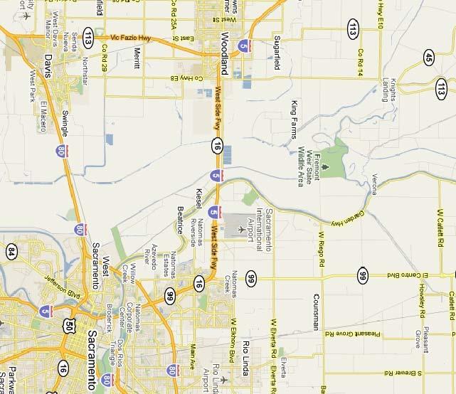
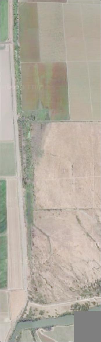
3 Fremont Weir Fish Passage Proof of Concept Introduction The Proof of Concept was initiated by DWR s Division of Flood Management (DFM) to investigate the feasibility of providing fish passage at Fremont Weir by making modifications to the weir and constructing channels from the Sacramento River to the Tule Canal (the east side drainage for Yolo Bypass). The initial goal was to provide 1,000 cubic feet per second (cfs) of water into Yolo Bypass year round, meaning that no more than 1,000 cfs could enter the bypass at high river stages and no less than 1,000 cfs when stages were low in the river. Additionally, one of the main problems that DFM wanted to solve was how to dissipate the energy of 15 to 20 vertical feet of water entering the bypass (when the river is at a high stage and the bypass is not) through a channel while maintaining favorable passage conditions for upstream migrating salmonids and sturgeon. This report details the design and modeling work that was completed to prove the concept. The results show that providing a connection from the Sacramento River to the bypass will work hydraulically and meet most of the initial goals for fish passage. The maximum flow into the bypass was limited to 1,000 cfs, but the goal of providing 1,000 cfs at low stages in the river was determined to not be feasible. It is possible to get 1,000 cfs into the bypass at low river stages, but this would require extensive lowering and widening of the existing channels downstream of the project site. For our design, the downstream channel was modified as little as possible and the flow into the bypass at low river stages was maximized as much as possible. Note: All elevations are in the NAVD88 datum. Goals, Assumptions, and Constraints Goals Provide a year-round flow connection from the Sacramento River to Yolo Bypass at all river stages Design fish passage through open channels to provide many diverse fish passage routes and to enhance the passage of sediment and debris. Prove that a geomorphically stable channel can be built to pass flow under a high head scenario (when the stage is high in the Sacramento River, but not overtopping the weir, and the Tule Pond and Canal are at low stages) Determine geometry, dimensions, invert elevation, slope, and materials for the fish passage channel(s) Determine the types of gates that can be used to shut off flow into the bypass Follow accepted fish passage design guidelines Provide passage for upstream migrating fish species, namely salmonids and sturgeon by: o Providing at least 2 feet of water depth within constructed channels o Ensuring that water velocities are lower than the swimming capabilities of the design fish species Maximize flow through the fish passage channel at low river stages Minimize the potential for excessive erosion or sedimentation Provide a connection between Fremont Weir s concrete apron and a fish passage channel 1
4 Minimize the amount of modification to the Tule Pond and Canal as much as possible Minimize upstream fish migration delays due to project operations, such as switching flow from one channel to another Provide vehicle access across the channels at river stages below 28.8 feet Use realistic Manning s n values for the modeling of all channels (existing and proposed) Keep design components below the elevation of the top of the weir Minimize flood impacts Keep the design as simple as possible Assumptions 1,000 cfs is less than the capacity of the Tule Canal. Therefore, this project will not inundate any of the floodplain downstream The topographic data that we have is of good quality The Manning s n values that we use for the existing Tule Canal are appropriate Using only four years of stage data (which is all that we have) for the Tule Pond is appropriate Data from the Tule Pond water level logger is accurate A minimum of 2 feet of depth is appropriate for sturgeon (regulatory agency criterion is 1 foot of depth for adult anadromous salmonids) Velocities near the banks and bottom of all the channels will be much lower than the average channel velocities shown in the models. Providing at least 2 feet of depth 89% of the time at low river stages is sufficient The Tule Pond and the wooded area downstream of the Tule Pond can be excavated Constraints Limiting the fish passage flow into Yolo Bypass to a maximum of 1,000 cfs when the river stage is below the top of the weir to avoid downstream floodplain inundation Limited to using available topographic and bathymetric data (however current, accurate, or minimal it may be) Limited time to complete the Proof of Concept design investigation Fish Passage Criteria and Recommendations Swimming speeds for Chinook salmon and steelhead are well documented. The widely recognized reference, the Fisheries Handbook of Engineering Requirements and Biological Criteria by Milo Bell (1991), gives sustained (prolonged) and darting (burst) swimming speeds for Chinook salmon and steelhead. Sustained swimming mode is used for passage through difficult areas and can be maintained for minutes. Darting swimming mode is generally used for feeding or escape, and therefore is a single effort and is not sustainable for extended periods of time. For Chinook salmon, sustained swimming speed is between 3 11 feet per second (fps) and darting speed is between fps. For steelhead, sustained swimming speed is between 5 15 fps and darting speed is between fps. The handbook does not provide any swimming speeds for sturgeon (Bell 1991). The swimming speeds represent the ability of salmonids to negotiate natural or engineered open channels and fish passage structures. DFG has developed fish passage criteria (2002) and NMFS has developed fish passage guidelines (2001) for adult anadromous salmonids. Both are intended for fish 2
5 passage through culverts. However, the culvert criteria can be used to inform the design of other fish passage structures. DFG s maximum cross-sectional velocity criteria for passage through culverts are shown in Table 1. NMFS guidelines are the same. The criteria are conservative and intended for the smaller and weaker fish of the population. The criteria are applied to the entire length of a culvert Table 1: Culvert Length vs Maximum Average Water Velocity for Adult Anadromous Salmonids (DFG 2002) Culvert Length (feet) Maximum Velocity (fps) < >300 2 or other hydraulically designed structures (DFG 2009). The minimum depth criterion for adult anadromous salmonids is one foot (DFG 2002, NMFS 2001). The depth criterion is applied to culverts, roughened channels, and other hydraulically designed structures for fish passage, and is the greatest depth in the channel or culvert cross section (DFG 2009). For sturgeon, a 2007 sturgeon swimming study report by DWR and UC Davis provides recent swimming ability data and passage recommendations for adult white sturgeon. The report indicated 7.0 fps for maximum water velocity through a slot and 3.3 feet or greater for depth as criteria for white sturgeon passage. The report also suggested that white sturgeon would be an appropriate surrogate for the federally listed green sturgeon in terms of swimming performance and physiological and behavioral parameters until any future green sturgeon studies develop species specific criteria. Based on the published salmonid passage criteria and the specific sturgeon study results, our design aimed to keep average channel velocities below 6 fps and depths greater than 2 feet. Velocities near the banks and bottom of all the channels will be much lower than the average channel velocities, and could be even lower if larger roughness elements, such as boulders, are added. Therefore, given that the fish passage channels should be designed to meet these criteria, the channels can be expected to be negotiable for adult salmonids and sturgeon, especially given the design roughness features that create hydraulic diversity within each channel. Hydrology Sacramento River stage data at Fremont Weir for years was downloaded from the California Data Exchange Center (CDEC) and parsed into months, and monthly stage exceedance percentages were calculated (Table 2). As shown in the table, 12 feet is exceeded at least 89% of the time in all months. It was assumed that providing 2 feet of depth at least 89% of the time is sufficient (91% or greater for October May), and therefore the channel invert elevation was set at 10 feet. Initial Modeling and Design Initially, we aimed to solve the problem of how to handle a high water surface differential between the Sacramento River and Yolo Bypass. This problem occurs when the Sacramento River is at a high stage 3
6 Table 2: Monthly Stage Exceedance Percentages for the Sacramento River at Fremont Weir SACRAMENTO RIVER AT FREMONT WEIR - MONTHLY PERCENT TIME STAGE IS EXCEEDED ( ) NAVD88 JAN FEB MAR APR MAY JUNE JULY AUG SEPT OCT NOV DEC >10' 100% 100% 100% 100% 100% 100% 100% 100% 100% 100% 100% 100% >11' 100% 100% 100% 99% 99% 98% 99% 100% 100% 100% 100% 100% >12' 100% 98% 100% 97% 93% 89% 93% 98% 100% 91% 92% 98% >13' 96% 96% 100% 90% 83% 76% 85% 89% 96% 77% 72% 93% >14' 89% 93% 94% 84% 70% 62% 80% 85% 84% 46% 60% 85% >15' 79% 83% 86% 72% 55% 49% 75% 76% 64% 24% 34% 67% >20' 44% 61% 60% 38% 18% 20% 6% 6% 3% 0% 9% 25% (but still below the top of Fremont Weir) and the bypass is not flooded. After analyzing four years of data (October 2002 June 2006) collected by a water level logger in the Tule Pond (about 4,500 feet south of the east abutment of Fremont Weir) and comparing it to stage data for the Sacramento River, it appears the maximum known water surface differential between the Sacramento River and the Tule Canal is feet. In addition, based on initial HEC-RAS modeling of our design, the water surface elevation in the Tule Pond is approximately 17 feet at 1,000 cfs. Since we needed our design to have a water surface elevation of 32.8 feet at Fremont Weir for 1,000 cfs of flow, our design would need to overcome a differential of 15.8 feet, which is more conservative than the differential based on water level logger data. To overcome this water surface elevation differential, we developed a design for a rock ramp roughened channel fishway. This fishway design overcomes the differential using three 900 foot long rock ramps constructed in series at a 0.55 % slope. The rock ramps are separated by 300 foot long pools constructed at a 0.00 % slope. The invert of the channel was set at 26.8 feet at Fremont Weir and the fishway would be shallow (6 feet deep) and wide (94 feet wide). The fishway would operate at stages above 28.8 feet, so there would be a minimum depth of 2 feet. This design resulted in average channel velocities between 1.9 and 6.7 feet per second. Next, we tried to design a second channel to pass fish for the remaining stages below those in which the rock ramp fishway would operate. To get the water surface in the second channel up to 28.8 feet at the weir for 1,000 cfs of flow, we had to severely narrow the channel cross-section. For example, one model run had a 500-foot-long, 15-foot-wide rectangular channel at the weir transitioning to an earthen trapezoidal channel with a 10-foot bottom width and 1:1 side slopes, connecting to the Tule Canal approximately 15,000 feet downstream. One of the negative outcomes of narrowing the channel crosssection was that flow into the channel at low river stages was very low. Flow in the channel was only 50 cfs when the river was at elevation 15 feet (5 feet of depth in the fish passage channel). Based on having to severely narrow the channel cross-section, use steep side slopes, and have low flows into the bypass at low river stages, we decided to abandon the two channel idea and increase the number of channels to three. Summary of Hydraulic Modeling The following sections describe the hydraulic modeling that was completed for the three channel fish passage concept. The channels are identified as low-stage (up to 20 feet), mid-stage (20 to 28.8 feet), and high-stage (28.8 feet and above). 4
7 Modeling Goals and General Model Assumptions The overall goal of the modeling was to prove that a three channel configuration would be feasible to improve fish passage at Fremont Weir. The channels were designed so that a maximum of 1,000 cfs would pass through each channel. As the Sacramento River rises and the low-stage channel reaches 1,000 cfs, that channel will be gated off, and the mid-stage channel gate will open (Table 3). Similarly, when the mid-stage channel reaches 1,000 cfs, it will be gated off, and the high-stage channel gate will be opened. As the stage in the Sacramento River drops, the process reverses (Table 4). The high-stage Table 3: Gate Operations When Sacramento River Stage is Rising from a Low Elevation (<15 feet) Water Surface Elevation at Fremont Weir (NAVD 88, feet) Channel Gate Opens Gate Closes Low-stage Open below Mid-stage High-stage 28.8 Open above 28.8 Table 4: Gate Operations When Sacramento River Stage is Falling from Flood Elevation (>32.8 feet) Water Surface Elevation at Fremont Weir (NAVD 88, feet) Channel Gate Opens Gate Closes High-stage Open above Mid-stage Low-stage 20 Open below 20 channel is designed to pass 1,000 cfs as the weir begins to overtop. The channels are designed so that approximately 2 feet of depth in each channel at Fremont Weir would be provided when its gate is opened. In addition to maximum capacity goals, a second goal was to provide as much flow as possible at 2 feet of depth in each channel, when the gates are initially opened. A third goal was to ensure that the maximum velocities were passable for the design species: salmonids and sturgeon. The three fish passage channels were modeled in the U.S. Army Corps of Engineers one-dimensional hydraulic modeling program, HEC-RAS. A different geometry file was created for each of the channels. For simplicity, the three fish passage channels were assumed to be the same length, approximately 3,700 feet. All three channels connect to the northern end of the existing Tule Pond. There is a wooded area south of the Tule Pond that is currently much higher in ground surface elevation than the invert of the Tule Pond. It was assumed that this area would be excavated to match more typical cross-sections upstream and downstream of this area. Since the low-stage channel invert is set at 10 feet at Fremont Weir, the Tule Pond and Canal will need to be excavated so that at low river stages water will flow downstream in the channel (the existing Tule Pond invert is ~12 feet). The slope of the low-stage channel, , was determined by connecting the invert at Fremont Weir (10 ) to a cross-section approximately 13,000 feet downstream of the weir. In HEC-RAS, a 25-foot-wide channel was excavated through the Tule Pond/Canal cross-sections to match the design slope of the low-stage channel. 5
8 Currently there are multiple scour channels oriented in a southeast direction from near the weir connecting to the Tule Pond. Survey data for these channels were not available, so they were not included in the modeling. While one of the new fish passage channels is flowing, it is possible there may be some backwater effect into these channels as well as into the other new fish passage channels. The models were run assuming steady-state conditions, and did not account for potential backwater in these channels. Survey Data used for HEC-RAS cross-sections The HEC-RAS cross-sections were created from several DWR surveys completed in the early 2000 s. Some of the cross-sections were unfinished (only a partial cross-section was surveyed) or appeared to have errors in the data. These were not included in the models. The survey data was imported into AutoCAD and alignments for each cross-section were drawn. Points within 25 feet on each side of the cross-section were plotted in Microsoft Excel and were then manually edited for input into HEC-RAS. The most downstream cross-section in the model is approximately 2,500 feet north of the I-5 crossing, near the USGS gaging station. The furthest upstream cross-section that is based on survey data is located at the northern end of the Tule Pond. All cross-sections in the models north of the Tule Pond were based on proposed channel designs. The farthest upstream cross-section for all the models is located at Fremont Weir. Since the spacing of cross-section data was not ideal, the built-in interpolation tool in HEC-RAS was used to interpolate between cross-sections so the model would run properly. Interpolations were used on the existing cross-sections as well as the design reaches. Boundary Conditions The models were run assuming subcritical flow, therefore only a downstream boundary condition was required. For a flow of 1,000 cfs, a water surface elevation of 14.6 feet (NAVD 88) was used for the downstream boundary condition, based on data from the USGS gaging station (north of I-5) downloaded from CDEC. Since the USGS gage is not rated below 1,000 cfs, the normal depth boundary condition was used for all other lower flow model runs. A downstream slope of was used, based on the average invert slope from the downstream boundary to approximately 12,000 feet upstream. Manning s n Values A Manning s n value of was assumed for Tule Canal and Tule Pond cross-sections, based on typical book values. Manning s n values for each of the three new fish passage channels were configured during the design process, as discussed in the sections below. The final values varied between and for the low-stage channel, and for the mid-stage channel, and and for the high-stage channel (See Design Elements section for roughness element descriptions). To simplify the modeling, the Manning s n value of a cross-section was assumed to be constant for all flows. Modeling Design Methods HEC-RAS geometry files were created for each of the three fish passage channels. An iterative process was used to find an ideal cross-section shape for each channel. Since the models were run assuming subcritical flow, HEC-RAS calculated water surface elevations starting from the downstream end of the model, working upstream. The models ended at Fremont Weir, so it was assumed that adequate flow could be provided from the Sacramento River through a channel upstream of Fremont Weir. The channel upstream of the weir as well as the details of the connection to the Sacramento River, were not investigated in this phase (although a connection is shown on the design drawings for clarity). If the initial cross-section dimensions did not provide adequate results, the cross-sections were modified slightly and the model was re-run. Besides cross-section dimensions, Manning s n values were adjusted 6
9 for the cross-sections to achieve the design goals. Over 70 HEC-RAS geometries were created to optimize the configurations of the three fish passage channels. Discussion of the Three Design Channels Since each fish passage channel will have a gate at Fremont Weir, a rectangular cross-section shape was used at this location. After 100 feet of channel length, a transition of feet (depending on the channel) from the rectangular shape to a trapezoidal cross-section was used. The rectangular and transition sections are made of concrete, and then embedded with roughness elements (e.g. cobbles and boulders) in the channel bottom and walls in order to achieve the Manning s n required by the design. The trapezoidal sections have a constant Manning s n until feet (depending on the design) upstream of the tie-in with the Tule Pond, where the channel shape and roughness will transition to meet the Tule Pond cross-section. Since each of the three fish passage channels has different Manning s n values for the sections, some field studies and/or literature review will be necessary to determine rock size and vegetation required to achieve the design n value. The following paragraphs describe each of the fish passage channels. For more details and drawings of the designs, please see the conceptual design drawings (Appendix A). Low-stage Channel The best low-stage channel design was determined to be a 100-foot-long, 26-foot-wide rectangular channel, followed by a 200-foot-long transition to a trapezoidal channel with a 26-foot-wide base and 1.5:1 side slopes. The channel is gradually graded from a location 800 feet upstream of the Tule Pond tie-in point, to meet the existing cross-section. The downstream slope of the low-stage channel is 0.006%. The Manning s n for the rectangular section is and the upstream transition section will have Manning s n values steadily increasing to 0.052, the roughness of the trapezoidal cross-sections. The 800-foot-long downstream transition has a Manning s n gradually decreasing from to 0.035, the value of the Tule Pond. Mid-stage Channel The best mid-stage channel design is a 100-foot-long, 15-foot-wide rectangular channel, followed by a 300-foot-long transition to a trapezoidal channel with a 10.5-foot-wide base and 1.5:1 side slopes. The trapezoidal channel is gradually graded from a location 800 feet upstream of the Tule Pond tie-in point, to meet the existing cross-section. The downstream slope of the mid-stage channel is 0.223%. The Manning s n for the rectangular section is and the upstream transition will have Manning s n values steadily increasing to 0.065, the roughness of the trapezoidal channel. The 800-foot-long downstream transition will have Manning s n gradually decreasing to 0.035, the value of the Tule Pond. High-stage Channel The best high-stage channel design was determined to be a 64-foot-wide rectangular cross-section with a 10-foot-wide, 2-foot-deep low-flow channel in the center transitioning to an 86-foot-wide trapezoidal shape with a 10-foot-wide low-flow channel. The rectangular cross-section is 100 feet long, followed by a 300-foot-long transitional section. The trapezoidal channel is gradually graded to meet the Tule Pond tie-in point, starting 600 feet upstream of the tie-in point. The downstream slope of the high-stage 7
10 channel is 0.461%. It should be noted that the channel invert is above the existing ground elevation over a significant length. Therefore, a significant amount of fill will be needed to construct the channel. The Manning s n for the rectangular section is and the upstream transition has Manning s n values steadily increasing to 0.068, which is the roughness of the trapezoidal channel. The 600-foot-long downstream transition has Manning s n gradually decreasing to 0.035, the Manning s n of the Tule Pond. Flows HEC-RAS modeling results were used to create the relationship between stage and flow for each channel (Figure 1). The low-stage channel was designed to be as wide as possible while allowing only 1,000 cfs at its maximum operable depth of 10 feet. Modeling results show that when there is 2 feet of depth (elevation 12 feet) at the weir the low-stage channel will flow at 20 cfs. This flow increases to 50 cfs at 3 feet of depth, 200 cfs at 5 feet of depth, and 500 cfs at 7.5 feet of depth. At 10 feet of depth (elevation 20 feet in the river) flow in the low-stage channel is 1,000 cfs. At this stage, the mid-stage channel will have a depth of 2 feet at the weir and the low-stage channel gate will close and the mid-stage channel gate will open (Table 3). Flow in the mid-stage channel will be 50 cfs shortly after the gate is opened. This flow increases to about 100 cfs at 3 feet of depth, 225 cfs at 5 feet of depth, and 500 cfs at 7.5 feet of depth. At 10 feet of depth (elevation 28.8 feet in the river) flow is 1,000 cfs. At this stage, the highstage channel will have a depth of 2 feet at the weir and the mid-stage channel gate will close and the high-stage channel gate will open. Modeling results show that the high-stage channel will flow at 45 cfs when there is 2 feet of depth at the weir. This flow increases to 140 cfs at 3 feet of depth, 360 cfs at 4 feet of depth, and 650 cfs at 5 feet of depth. At 6 feet of depth, when the river stage is at the top of the weir, flow is 1,000 cfs. Profiles Water surface elevation profiles and velocity profiles over a range of flows are provided at the end of this report (Figures 2-7). At 1,000 cfs, velocities range from <1.0 to about 3.7 fps in the low-stage channel, <2.0 to about 6.3 fps in the mid-stage channel, and <1.5 to about 4.1 fps in the high-stage channel. Note that the pattern of the profiles for 1,000 cfs differ from the lower flow profiles because a boundary condition based on a known water surface elevation was used for 1,000 cfs in the model. For all other flows, a normal depth boundary condition was used in the model. Normal depth is the depth of flow in a channel when the slope of the water surface and channel invert is the same, and water depth is constant. Design Elements From the modeling effort, we came up with the design elements for the three channels. For the lowstage channel, the rectangular concrete section, the concrete transitional section, and the trapezoidal section will have a natural substrate (except at the gate structure) called engineered streambed material (ESM). The ESM will be a mix of particle sizes ranging from large cobbles (10 inch) down to sand and silt (Table 5), and will be the same for all three channels. The upstream transitional section will gradually increase in roughness in the downstream direction. This increased roughness will be due to vegetation growing on the bed of the channel (types of plants to be determined) which will increase the Manning s roughness from to The banks of the trapezoidal channel will be composed of a bankline rock mix, with particles ranging from 1.3 foot facing rock down to sand and silt (Table 5). The bankline rock mix will be the same for all three channels. In addition, the banks of the trapezoidal channel will be vegetated (types of plants to be determined). The rectangular channel is gated at the weir with a wall 8
11 extending from elevation 20 feet up to the top of the weir at 32.8 feet (see Gates section and design drawings). For the mid-stage channel, the rectangular concrete section, the concrete transitional section, and the trapezoidal section will have a substrate of ESM (except at the gate structure). The ESM will have some larger boulders randomly scattered to provide additional roughness and resting areas for upstream migrants. The upstream transitional section will gradually increase in roughness in the downstream direction. This increased roughness will be due to vegetation growing on the bed of the channel (types of plants to be determined) which will increase the Manning s roughness from to This vegetation will continue into the trapezoidal channel. The banks of the trapezoidal channel will be composed of the bankline rock mix. In addition, the banks of the trapezoidal channel will be vegetated (types of plants to be determined). The rectangular channel is gated at the weir (see Gates section and design drawings). For the high-stage channel, the rectangular concrete section, the concrete transitional section, and the trapezoidal section will have a substrate of ESM (except at the gate structure). The ESM will have some larger boulders randomly scattered to provide additional roughness and resting areas for upstream migrants. The upstream transitional section will gradually increase in roughness in the downstream direction. This increased roughness will be due to vegetation growing on the bed of the channel (types of plants to be determined) which will increase the Manning s roughness from to This vegetation will continue into the trapezoidal channel. The banks of the trapezoidal channel will be composed of the bankline rock mix. In addition, the banks of the trapezoidal channel will be vegetated (types of plants to be determined). The rectangular section of the high-stage channel will have a 2-foot-tall, 10-foot-wide gate (see Gates section and design drawings) to shut off flow in its low-flow portion, but in lieu of a full channel gate, a flashboard type dam was assumed to be a much cheaper option to shut off flow in the upper portion of this channel. Material Mixes (for all constructed channels) Engineered Streambed Material (ESM) Mix Table 5: Material Mixes Bankline Rock Mix 7 parts 2.5" very coarse gravel to 10" cobbles 5 parts Facing Rock (4" to 1.3') 4 parts 1.26" to 2.5 " very coarse gravel 5 parts 2.5" very coarse gravel to 4 " cobbles 5 parts 0.31" med gravel to 1.26" coarse gravel 7 parts 0.31" med gravel to 2.5" very coarse gravel 2 parts 0.079" very fine gravel to 0.31" fine gravel 1 part 0.079" very fine gravel to 0.31" fine gravel 2 parts silt to 0.079" very coarse sand 2 parts silt to 0.079" very coarse sand Design Layout The three channels run side-by-side near the east levee of Yolo Bypass and converge at the Tule Pond approximately 3,700 feet downstream of the east abutment of the weir (see design drawings in Appendix A). The rectangular channels are currently separated but could be brought closer together (potentially sharing concrete walls). The low-stage and mid-stage rectangular channels will have bridges 9
12 across them to allow vehicle access to the interior of the bypass. The high-stage channel will have a lowwater crossing a short distance upstream of the weir. We did not do much work designing a channel from the Sacramento River to the Fremont Weir. This is because the main emphasis was proving that fish passage could work from downstream of the weir to the weir itself. For the sake of clarity, we do show a simple channel from the river to the weir on the design drawings. Operations One major drawback of the three channel design is fish delay associated with flow changes due to the operation of the three channels. For example, as stage increases to 20 feet in the Sacramento River, flow of 1,000 cfs is gated off in the low-stage channel and a much smaller flow of 50 cfs will begin flowing through the mid-stage channel after its gate is opened. In addition to the flow being greatly reduced, upstream migrating fish in the 3,700 foot long low-stage channel will be delayed as they try to find the open mid-stage channel. This problem is one that we would like to solve or at least minimize in the next design phase. To aid in gate operations, it may be possible to use River Guidance Plots, available at the California Data Exchange Center, which provide predictions of future stages at Fremont Weir. Gates Flow into the low-, mid-, and high-stage channels will be controlled by gates at Fremont Weir. For this feasibility-level analysis, we researched a variety of gate types and actuation systems to determine if we have a feasible concept. The goals for the gate design were to present some feasible alternatives that reliably route water to the desired channel, minimize the potential for debris accumulation and hydraulic impacts during weir overtopping, minimize aesthetic impacts (avoid a large superstructure above the existing weir), minimize maintenance requirements, control the gates from a remote location, and keep construction and maintenance costs in the range of feasibility. Gate types A variety of gate types would satisfy the goals for this project. These include vertical lift gates, hinge crest gates, Obermeyer gates, radial gates, and miter gates. We spoke with several gate manufacturers who were confident that they could provide gates that would satisfy the goals of the project. Low-stage channel gate (height = 10 feet): A hydraulically actuated vertical lift gate could work for this application. In the closed position the gate would rest on the channel invert. To allow flow into the channel, the gate would be lifted up so the top of the gate would rest slightly below the existing top of Fremont Weir. Hydraulically or air actuated hinged crest gates are another feasible alternative. The hinge could either be along the channel invert, raising the gate up to close off the channel, or the hinge could be placed at the top of the low-stage channel near elevation 20 feet, and lowering the gate to close the channel. Mid-stage channel gate (height = 14.8 feet): The hinged crest gate is a good alternative for this application, with the hinge along the invert of the channel at elevation 18 feet. The top of this gate would be flush with the adjacent crest of the existing 10
13 weir. The gate would nest along the invert of the channel when open, and rotate up to close. Vertical lift gates and radial gates are not recommended for this channel because they would extend above the weir crest elevation in the open position. High-stage channel gate (height = 2 feet): The purpose of this gate is to prevent water from entering the high-stage channel during stages of insufficient depth for sturgeon to swim (assumed to be less than 2 feet). The gate would only be actuated (closed) during stages from 26.8 to 28.8 feet. This would be a good case for a hydraulically or air bladder actuated hinged crest gate. Gate actuation Three actuation alternatives were researched: hydraulic, air, and electrical activation. Due to the requirement for an electrical gate actuation system to be placed above the flood stage and directly above the gate structure, this actuation type is not recommended. Hydraulic and air actuation allow for a low-profile actuation and both involve similar design requirements. The power supply and auxiliary equipment for either system would be placed in a building above the flood stage. This equipment could be placed on a small pad adjacent to the top of the existing east levee. Hydraulic fluid or air lines would be routed from the auxiliary equipment building to each individual gate, where hydraulic cylinders or Kevlar air bladders would open and close the gates. Both hydraulic and air actuation systems can be operated from a remote site. The hydraulic actuation system provides additional redundancy with the capability to utilize accumulators, devices that store energy, to actuate the gates in the event of a loss of power. This would provide a margin of safety during high flow events, where the low- and mid-stage channel gates will be required to be closed. Conclusions Fish passage at Fremont Weir is feasible. We designed three channels that will allow fish passage at almost all stages in the Sacramento River (the low-stage channel will not meet the adult anadromous salmonid depth criterion at stages below 11 feet). Depths in the designed channels are greater than 2 feet and average velocities are less than 6.3 fps, meaning that the channels will be negotiable for salmonids and should be negotiable for sturgeon, especially given the diversity that each channel will provide to these fish species. The high-stage channel is able to handle a stage differential of over 15 feet from the river to the Tule Canal and, due to its wide and shallow cross-section, will keep average water velocities under 4.2 fps. The engineered substrate of this channel and the other two channels is designed to remain stable and is composed of a mix of particle sizes from 10 cobbles down to sand and silt, with larger boulders randomly scattered to provide additional roughness and resting areas for upstream migrants. The bankline rock mix for the channels will ensure that the banks will not erode. Both the bed and bank material mixes will allow vegetation to grow, which will provide additional roughness. The mid- and low-stage channels have maximum average velocities of 6.3 and 3.7 fps, respectively. The low-stage channel is designed to pass as much water as possible at low river stages and still provide 1,000 cfs when flowing at its maximum capacity. The low-stage channel will pass 50 cfs when the river is at 13 feet, and river stages are greater than that approximately 72% of the time in October and more in all other months. When the river is at 15 feet, the low-stage channel will pass 200 cfs. Velocities at higher flows in all of the channels should be enough to keep sedimentation to a minimum. 11
14 There are some issues to work out with this design, such as the delay of fish migration and changing flow regimes due to gate operations. New bathymetric surveys and detailed modeling will result in an accurate estimate of the flow capacity of the Tule Canal which may be larger than expected, possibly giving us a larger flow to work with for fish passage and more flexibility in design. More flow may allow us to develop a feasible two channel design, which would help to reduce the delay problem. We have completed a conceptual design for fish passage at Fremont Weir, which is a starting point for future design work. More work is needed to refine this concept and determine a preferred alternative for fish passage at Fremont Weir. Next Steps Below is a list of tasks that we see as important for the immediate future of this project: Investigate other design configurations (see Steve Thomas design in Appendix B). Collect more detailed and current topography and bathymetry data for the northern Yolo Bypass. Along with floodplain elevation points, cross-sections in the Tule Canal should be resurveyed due to discrepancies among the previous surveys. It is possible this has already been done and the data may just need to be purchased. To improve the boundary conditions for the low-flow model runs, a stage vs. flow relationship for flows less than 1,000 cfs should be developed for the channel at the location of the USGS gage north of I-5, the downstream boundary of the models. Model the Tule Canal and Toe Drain to determine the capacity to see if we can increase the maximum flow through the fish passage channels. Investigate the impact of fish passage flows on downstream water operations in Yolo Bypass. Since the Manning s n values were estimated at for the existing Tule Canal cross-sections, this value should be verified (or adjusted to the correct value). Water surface elevations throughout the lower reach of the model should be recorded over a range of flows, to calibrate the model in this area and determine appropriate n values. Investigate lowering the high-stage channel invert by several feet to determine if a two channel design is feasible. Seek review and detailed input from fishery biologists and experts in fish passage design. The connection between the Sacramento River and the Fremont Weir was not investigated in this phase (although we do show a potential design for this channel). Modeling (possible 2-D or 3-D) of this area may be necessary in a future phase to ensure proper hydraulics at the Sacramento River and fish passage channel interface. Investigate influence of flood flows and Sutter Bypass input on project components. 12
15 Examine overlapping the channel gate operations more (e.g. providing 3 feet of depth before opening the next channel). Minimize the fish delay problem in the closed channels. Determine preferred gate alternatives. Design a connection from the apron of Fremont Weir to the low-stage channel. Determine the approximate project costs and earthwork quantities. References Bell, Milo Fisheries Handbook of Engineering Requirements and Biological Criteria. U.S. Army Corps of Engineers, North Pacific Division, Portland, Oregon. California Department of Fish and Game (DFG) Appendix IX-A, Culvert Criteria for Fish Passage. In the California Salmonid Stream Habitat Restoration Manual ( rd edition). California Department of Fish and Game (DFG) Part XII, Fish Passage Design and Implementation. In the California Salmonid Stream Habitat Restoration Manual ( rd edition). P. XII-i to XII-C-12. NOAA, National Marine Fisheries Service (NMFS) Guidelines for Salmonid Passage at Stream Crossings. NMFS, Southwest Region. 13
16 Figure 1: Flow vs Stage Relationship for Fish Passage Channels at Fremont Weir (based on HEC-RAS modeling) 14
17 Figure 2: Water Surface Elevation Profiles for the Low-stage Channel 15
18 Figure 3: Water Surface Elevation Profiles for the Mid-stage Channel 16
19 Figure 4: Water Surface Elevation Profiles for the High-stage Channel 17
20 Figure 5: Velocity Profiles for the Low-stage Channel 18
21 Figure 6: Velocity Profiles for the Mid-stage Channel 19
22 Figure 7: Velocity Profiles for the High-stage Channel 20
23 Appendix A Conceptual Design Drawings
24
25
26
27
28
29
30 Appendix B Comments

31 The design report was reviewed by Steve Thomas (NMFS Fisheries Engineering Team) and George Heise (DFG Fisheries Engineering Team). Below are comments received from them regarding our conceptual design for Fremont Weir fish passage. Comments from Steve Thomas To expedite a response I want to provide some informal comments here topics for discussion and for your consideration. We can discuss next week and later I can provide more formal comments if you want. Firstly, it looks like you put a lot of effort into optimizing the concept. The plots and drawings help show how the concept would work. As you and I already discussed, there are a couple downsides to the concept, namely, stepped discharges going up and down with flow and the possibility of stranding fish as flow is cut off from channels. I was wondering if the lower channels could be used while the upper channels were in service to reduce the cycling of channels (the lower channel would rarely or never be dewatered) and make up water could be discharged through a lower channel while passage is provided at higher channels. The attached diagram (BELOW) is one concept I ve been running through my head. To explain the diagram, at lower stages flow is confined to the lowest channel only (Channel 1) up to your target flow (1,000 cfs). As the river stage rises, an undershot gate on Channel 1 (Gate 1) closes partially to reduce flow in Channel 1 and a gate opens on the middle stage channel (Channel 2, Gate 2). Fish passage can continue through Gate 1 if the head across the gate is limited to feet. Channel 2 discharges into Channel 1 so Channel 1 does double duty and isn t dewatered as the Sac River stage increases. The same thing happens with Channel 3 as stage increases. I haven t analyzed the hydraulics over the expected range of flow, but I thought an arrangement like this could have several benefits. I think you d need to develop the flow scheme and design the channels to meet those goals such as you did with the other design. A technical-type of fish ladder would probably work better for this type of layout, but sturgeon don t do well in technical ladders, and I ve never seen a technical ladder with a 1,000 cfs
32 capacity. For a nature-like fishway you d need wide sweeping bends in the channel and enlarged turning pools or confluences to dissipate energy and avoid distracting turbulence. Brent Mefford at USBR s TSC in Denver designed a high flow ladder for use at a dam in southern California. I and some others explored the abilities of that ladder concept to work over a range of design flows at another dam in so. Cal. Brent posted a video of a model of his design (Robles) on his web page. It looks promising but is unproven in the real world. Randy also discussed the project with George Heise (DFG Fisheries Engineering Team) and learned that he will not be able to provide detailed comments at this time. He did say that he thought that providing better fish passage at Fremont Weir is a very important project and that he generally supported our concept, but has concerns about the switching of flow from one channel to another and possibly stranding fish in the channel that has been shut off. He also said that he did speak with Steve Thomas and thought that Steve s idea is a good one. Randy discussed with George his concerns about how Steve s fishway would operate, or handle flows once the weir is overtopped, since we still may want to pass sturgeon through a fishway when stages are possibly up to 3 feet over the top of the weir. In addition, Stein Buer spoke with Robin Kulakow, Executive Director of the Yolo Basin Foundation. She voiced her concern regarding the impact that adding flow into the Yolo Bypass at Fremont Weir would have on the Yolo Bypass Wildlife Area. In the summer, Toe Drain water levels need to be low enough to allow the wildlife area ponds to drain efficiently before the wet season to facilitate food production, control noxious species, etc..
SELBY CREEK SILVERADO TRAIL CULVERT FISH PASSAGE ASSESSMENT
 SELBY CREEK SILVERADO TRAIL CULVERT FISH PASSAGE ASSESSMENT NAPA COUNTY, CALIFORNIA PREPARED BY NAPA COUNTY RESOURCE CONSERVATION DISTRICT 1303 JEFFERSON ST. SUITE 500B NAPA, CALIFORNIA 94559 WWW.NAPARCD.ORG
APPENDIX C VEGETATED EMERGENCY SPILLWAY. VERSION 1.0 March 1, 2011
 APPENDIX C VEGETATED EMERGENCY SPILLWAY VERSION 1.0 March 1, 2011 [NOTE: Could use a better photo more clearly showing the emergency spillway in the context of the dam.] SECTION C-1: DESCRIPTION OF PRACTICE
Plan B Dam Breach Assessment
 Plan B Dam Breach Assessment Introduction In support of the Local Sponsor permit applications to the states of Minnesota and North Dakota, a dam breach analysis for the Plan B alignment of the Fargo-Moorhead
Colusa Basin Drain Watershed Fish Stranding Tour Concept Paper Mike Hendrick and Brycen Swart NMFS
 Colusa Basin Drain Watershed Fish Stranding Tour Concept Paper Mike Hendrick and Brycen Swart NMFS On May 31, 2013 representatives from CDFW, USFWS, and NMFS went on a field tour to look at locations in
USING A LABYRINTH WEIR TO INCREASE HYDRAULIC CAPACITY. Dustin Mortensen, P.E. 1 Jake Eckersley, P.E. 1
 USING A LABYRINTH WEIR TO INCREASE HYDRAULIC CAPACITY Dustin Mortensen, P.E. 1 Jake Eckersley, P.E. 1 Plum Creek Floodwater Retarding Structure No. 6 is located in an area of Kyle, Texas, that is currently
Rock Ramp Design Guidelines. David Mooney MS Chris Holmquist-Johnson MS Drew Baird Ph.D. P.E. Kent Collins P.E.
 Rock Ramp Design Guidelines David Mooney MS Chris Holmquist-Johnson MS Drew Baird Ph.D. P.E. Kent Collins P.E. Rock Ramp Design Guidelines OUTLINE Local and System Interactions with Rock Ramps Ramp Geometry
JAP Additional Information Sheet
 JAP Additional Information Sheet Block 15: Purpose and Need The USACE purpose of the project is to provide a safe and reliable whitewater park for the recreational public in a city park, which will provide
Aquatic Organism Passage at Road-Stream Crossings CHUCK KEEPORTS FOREST HYDROLOGIST ALLEGHENY NATIONAL FOREST WARREN, PENNSYLVANIA
 Aquatic Organism Passage at Road-Stream Crossings CHUCK KEEPORTS FOREST HYDROLOGIST ALLEGHENY NATIONAL FOREST WARREN, PENNSYLVANIA TOPICS COVERED Aquatic Organism Passage (AOP) Benefits of AOP Crossings
Culvert Design for Low and High Gradient Streams in the Midwest. Dale Higgins, Hydrologist Chequamegon-Nicolet National Forest
 Culvert Design for Low and High Gradient Streams in the Midwest Dale Higgins, Hydrologist Chequamegon-Nicolet National Forest Overview Culvert Design Considerations Hydraulic Terms Culvert Impacts Low
FISH PASSAGE IMPROVEMENT in California s Watersheds. Assessments & Recommendations by the Fish Passage Forum
 FISH PASSAGE IMPROVEMENT in California s Watersheds Assessments & Recommendations by the Fish Passage Forum FISH PASSAGE IMPROVEMENT in California s Watersheds The mission of the Fish Passage Forum is
CALIFORNIA SALMONID STREAM HABITAT RESTORATION MANUAL APPENDIX IX-A CULVERT CRITERIA FOR FISH PASSAGE INTRODUCTION
 APPENDIX IX-A STATE OF CALIFORNIA RESOURCES AGENCY DEPARTMENT OF FISH AND GAME CULVERT CRITERIA FOR FISH PASSAGE For habitat protection, ecological connectivity should be a goal of stream-road crossing
APPENDIX J HYDROLOGY AND WATER QUALITY
 APPENDIX J HYDROLOGY AND WATER QUALITY J-1 Technical Report on Airport Drainage, Northern Sector Airport and Ordinance Creek Watershed / Preliminary Creek Constructed Natural Channel Culvert J-2 Preliminary
STRUCTURE S-65 PURPOSE SPILLWAY OPERATION
 STRUCTURE S-65 This structure is a reinforced concrete, gated spillway with discharge controlled by three cable operated, vertical lift gates, and a reinforced concrete lock structure with two pairs of
Hydraulic Modeling of Stream Enhancement Methods
 Hydraulic Modeling of Stream Enhancement Methods Matthew J. Curry John J. Levitsky Abstract Development within watersheds increases the amounts of runoff causing stream erosion and degradation of stream
Packwood Hydroelectric Project Barrier Analysis December 12, 2006
 Packwood Hydroelectric Project Barrier Analysis December 12, 2006 Study Area Natural barriers to upstream fish passage on Lake Creek at RM 1.03 and RM 1.95 Snyder Creek culvert under the Project tailrace
Five Counties Salmonid Conservation Program - Fish Passage Design Workshop. February 2013
 Program - Aquatic Organisms and Stream Crossings Ecological Connectivity A watershed is a network of channels that drain a common boundary. Channel characteristics formed by interaction of precipitation,
Subject: Developed fish ladder alternatives for Pastori Avenue at San Anselmo Creek
 Page 1 of 18 SENT VIA EMAIL Sandra Guldman Friends of Corte Madera Creek Watershed Box 415 Larkspur, CA 94977 Subject: Developed fish ladder alternatives for Pastori Avenue at San Anselmo Creek Dear Sandra,
Redd Dewatering and Juvenile Salmonid Stranding in the Lower Feather River,
 Redd Dewatering and Juvenile Salmonid Stranding in the Lower Feather River, 2005-2006 Interim Report for NOAA Fisheries Prepared by: California Department of Water Resources Division of Environmental Services
Discussion on the Selection of the Recommended Fish Passage Design Discharge
 Discussion on the Selection of the Recommended Fish Passage Design Discharge Introduction The provision of fish passage is a requirement for most proposed culvert and bridge installations in Alberta, depending
FSOC Upstream Fish Passage Guidance Document
 FSOC Upstream Fish Passage Guidance Document STEP 1: Identify species and life stages in need of fish passage STEP 2: Identify fishway options and species applicability STEP 3 Fish passage criteria review
Applying Engineering Solutions to the Science of Protection and Enhancement of Aquatic Environments. Bill Holman, P.E. Stanley Consultants
 Applying Engineering Solutions to the Science of Protection and Enhancement of Aquatic Environments Bill Holman, P.E. Stanley Consultants Project Development PHASE STAGE TASKS PURPOSE I II III Investigation
Corte Madera Creek Flood Control Channel
 Corte Madera Creek Flood Control Channel Prepared for Friends of Corte Madera Creek Watershed Marin County Flood Control and Water Conservation District U.S. Army Corps of Engineers Prepared by Michael
Understanding the Impacts of Culvert Performance on Stream Health
 Understanding the Impacts of Culvert Performance on Stream Health Kristin Thomas Aquatic Ecologist Michigan Trout Unlimited Transportation and the Environment Conference 12/5/2018 Importance of adequately
The Hydraulic Design of an Arced Labyrinth Weir at Isabella Dam
 Utah State University DigitalCommons@USU International Symposium on Hydraulic Structures Jun 28th, 1:30 PM The Hydraulic Design of an Arced Labyrinth Weir at Isabella Dam E. A. Thompson Sacramento District
APPENDIX B HYDRAULIC DESIGN DATA FOR CULVERTS
 TM 5-820-4/AFM 88-5, Chap 4 APPENDIX B HYDRAULIC DESIGN DATA FOR CULVERTS B-1. General. a. This appendix presents diagrams, charts, coefficients and related information useful in design of culverts. The
OFFICE OF STRUCTURES MANUAL FOR HYDROLOGIC AND HYDRAULIC DESIGN CHAPTER 11 APPENDIX B TIDEROUT 2 USERS MANUAL
 OFFICE OF STRUCTURES MANUAL FOR HYDROLOGIC AND HYDRAULIC DESIGN CHAPTER 11 APPENDIX B TIDEROUT 2 USERS MANUAL APRIL 2011 APRIL 2011 Page 1 Preface TIDEROUT 2, Build 1.22 dated June 29, 2006 is the current
Components of a Barrage
 Components of a Barrage Definition The only difference between a weir and a barrage is of gates, that is the flow in barrage is regulated by gates and that in weirs, by its crest height. Barrages are costlier
HYDRAULIC JUMP AND WEIR FLOW
 HYDRAULIC JUMP AND WEIR FLOW 1 Condition for formation of hydraulic jump When depth of flow is forced to change from a supercritical depth to a subcritical depth Or Froude number decreases from greater
Applying Engineering Solutions to the Science of Invasive Aquatic Species Control Asian Carp and Sea Lamprey. Bill Holman, P.E. Stanley Consultants
 Applying Engineering Solutions to the Science of Invasive Aquatic Species Control Asian Carp and Sea Lamprey Bill Holman, P.E. Stanley Consultants Sea Lamprey: Great Lakes Invader Lake Superior Sea Lamprey
HY-8 Version 7.2 Build Date January 17, Federal Highway Administration.
 HY-8 Version 7.2 Build Date January 17, 2012 Federal Highway Administration http://www.fhwa.dot.gov/engineering/hydraulics/software/hy8/index.cfm SIMPLE Simple to use Use for simple culverts and bridges
Annex E Bridge Pier Protection Plan
 Annex E Bridge Pier Protection Plan Table E1 Bridge Types and Locations Table E2 Flow Conditions For River Sections Figure E1 Bridge Abutment Protection Figure E2 Bridge Pier Protection Figure E3 Central
Fish Passage Assessment of Private Stream Crossings on Lower Stonybrook Creek
 Fish Passage Assessment of Private Stream Crossings on Lower Stonybrook Creek Prepared by: Michael Love & Associates In cooperation with: Center for Ecosystem Management and Restoration Funded by: Coastal
(Revised February,2005) CULVERTS, BRIDGES, AND FORDS
 CULVERTS, BRIDGES, AND FORDS") GUIDE TO STREAM CROSSINGS (Revised February,2005) CULVERTS, BRIDGES, AND FORDS Culverts, bridges, and fords are all methods used to cross-streams. Culverts are the most common stream crossing structure.
GUIDE TO STREAM CROSSINGS (Revised February,2005) CULVERTS, BRIDGES, AND FORDS Culverts, bridges, and fords are all methods used to cross-streams. Culverts are the most common stream crossing structure.
STRUCTURE 65-B PURPOSE SPILLWAY OPERATION
 STRUCTURE 65-B This structure is a reinforced concrete, gated spillway with discharge controlled by three cable operated vertical lift gates and a reinforced concrete lock structure with two pairs of sector
Final Bull Trout Genetics Monitoring Plan for the Wallowa Falls Hydroelectric Project. (FERC No. P-308) June 2017
 June 2017") Final for the Wallowa Falls Hydroelectric Project (FERC No. P-308) June 2017 Prepared by: Jeremiah Doyle PacifiCorp 825 NE Multnomah Street Portland, OR 97232 June, 2017 Page 1 of 8 Table of Contents 1.0
Final for the Wallowa Falls Hydroelectric Project (FERC No. P-308) June 2017 Prepared by: Jeremiah Doyle PacifiCorp 825 NE Multnomah Street Portland, OR 97232 June, 2017 Page 1 of 8 Table of Contents 1.0
PROFILE OF SACRAMENTO RIVER, FREEPORT TO VERONA, CALIFORNIA,
 PROFILE OF SACRAMENTO RIVER, FREEPORT TO VERONA, CALIFORNIA, FLOOD OF FEBRUARY 1986 By J.C. Blodgett and J.B. Lucas U.S. GEOLOGICAL SURVEY Open-File Report 88-82 CO CM I m r-h CM Sacramento, California
A THESIS M.S. CIVIL ENGINEERING UNIVERSITY OF ALASKA ANCHORAGE ALEXANDRA WEST JEFFERIES, P.E.
 Assessing Fish Passage Success in Culvert Structures with the Development of a Two-Dimensional Algorithm Considering Physical Capabilities of Juvenile Salmonids ALEXANDRA WEST JEFFERIES, P.E. A THESIS
Big Spring Creek Habitat Enhancement and Fishery Management Plans
 Big Spring Creek Habitat Enhancement and Fishery Management Plans November 5, 2012 Big Spring Events and Activities Center Newville, PA Charlie McGarrell Regional Habitat Biologist Pennsylvania Fish and
Appendix G Whitewater Recreation Flow Study Plan
 Appendix G Whitewater Recreation Flow Study Plan Study Plan Whitewater Recreation Flow Study Grandfather Falls Hydroelectric Project FERC Project No. 1966 March 2013 An Integrys Energy Group Company Section
Sediment Basin 7E-12. Design Manual Chapter 7 - Erosion and Sediment Control 7E - Design Information for ESC Measures BENEFITS.
 7E-12 Design Manual Chapter 7 - Erosion and Sediment Control 7E - Design Information for ESC Measures Sediment Basin BENEFITS Flow Control Erosion Control Sediment Control Runoff Reduction Flow Diversion
Session C9: Priest Rapids Fish Bypass: A Case Study from Start to Finish
 University of Massachusetts - Amherst ScholarWorks@UMass Amherst International Conference on Engineering and Ecohydrology for Fish Passage International Conference on Engineering and Ecohydrology for Fish
Follow this and additional works at:
 University of Massachusetts Amherst ScholarWorks@UMass Amherst International Conference on Engineering and Ecohydrology for Fish Passage International Conference on Engineering and Ecohydrology for Fish
St. Mary Diversion Dam Case Study of a 100 year Old Diversion
 Utah State University DigitalCommons@USU International Symposium on Hydraulic Structures Jun 29th, 4:00 PM - 6:00 PM St. Mary Diversion Dam Case Study of a 100 year Old Diversion B. J. Heiner U.S. Bureau
BATTLE CREEK FISHERIES STUDIES TASK 4: SURVEYS OF BARRIERS TO THE UPSTREAM MIGRATION OF ANADROMOUS SALMONIDS
 BATTLE CREEK FISHERIES STUDIES TASK 4: SURVEYS OF BARRIERS TO THE UPSTREAM MIGRATION OF ANADROMOUS SALMONIDS Prepared for: California Department of Fish and Game Redding, California 96001 Prepared by:
FISH PASSAGE ALTERNATIVES ANALYSIS ON PENNYPACK CREEK AT VERREE ROAD DAM AND ROOSEVELT BOULEVARD DAM PHILADELPHIA, PENNSYLVANIA
 FISH PASSAGE ALTERNATIVES ANALYSIS ON PENNYPACK CREEK AT VERREE ROAD DAM AND ROOSEVELT BOULEVARD DAM PHILADELPHIA, PENNSYLVANIA Prepared for: One Parkway, 10 th Floor 1515 Arch Street Philadelphia, PA
Presented by Fred Halterman, URS Jennie Agerton, URS
 Presented by Fred Halterman, URS Jennie Agerton, URS What is Eco Friendly Culvert Design? Culvert design that: Maintains connectivity for aquatic organism migration Maintains connectivity for gene flow
Washington State Fish Passage Barrier Removal Projects. Casey Kramer, PE WSDOT State Hydraulics Engineer
 Washington State Fish Passage Barrier Removal Projects Casey Kramer, PE WSDOT State Hydraulics Engineer 2014 National Hydraulic Engineering Conference Iowa City, IA August 20 th, 2014 WSDOT Fish Passage
APPENDIX C. Fluvial and Tidal Hydraulics Report
 APPENDIX C Fluvial and Tidal Hydraulics Report BUENA VISTA LAGOON ENHANCEMENT PROJECT FLUVIAL AND TIDAL HYDRAULICS ANALYSES Prepared for: SANDAG 401 B Street, Suite 800 San Diego, California 92101 Contact:
Indiana LTAP Road Scholar Core Course #10 Culvert Drainage. Presented by Thomas T. Burke, Jr., PhD, PE Christopher B. Burke Engineering, Ltd.
 Indiana LTAP Road Scholar Core Course #10 Culvert Drainage Presented by Thomas T. Burke, Jr., PhD, PE Christopher B. Burke Engineering, Ltd. Objectives Review culvert shapes, end sections, and materials
Stevens Creek Corridor
 O F F I C E O F T H E D I R E C T O R O F P U B L I C W O R K S Stevens Creek Corridor Creek Restoration Project Volume Three Project Update: Creek Photos, Before & After BY GAIL SEEDS - PROJECT MANAGER,
Suitable Applications Check dams may be appropriate in the following situations: To promote sedimentation behind the dam.
 Categories EC Erosion Control SE Sediment Control TC Tracking Control WE Wind Erosion Control Non-Stormwater NS Management Control Waste Management and WM Materials Pollution Control Legend: Primary Category
Request Number IR1-12: Flow Passage. Information Request
 Request Number IR1-12: Flow Passage Information Request Provide additional information about the 100 metre flow passage channel scenario between the Westshore Terminals and the proposed Project terminal
FINAL Caples Lake Fisheries Management Plan. Version 4.0
 FINAL Caples Lake Fisheries Management Plan Version 4.0 August 15, 2008 Purpose The Caples Lake Fisheries Management Plan (Plan) outlines the stocking plan to reestablish a sport fishery in Caples Lake
 Dam Modification Report Stingy Run Fly Ash Reservoir Appendix E Spillway System Design Calculations E1: Spillway/Energy Dissipater Design for 100-year Event CHE8273 8 September 4, 2014 Written by: CJW
Chadbourne Dam Repair and Fish Barrier
 Chadbourne Dam Repair and Fish Barrier Final Report for the Western Native Trout Initiative Prepared by: Carol Endicott Yellowstone Cutthroat Trout Conservation Biologist Montana Fish, Wildlife & Parks
Ermenek Dam and HEPP: Spillway Test & 3D Numeric-Hydraulic Analysis of Jet Collision
 Ermenek Dam and HEPP: Spillway Test & 3D Numeric-Hydraulic Analysis of Jet Collision J.Linortner & R.Faber Pöyry Energy GmbH, Turkey-Austria E.Üzücek & T.Dinçergök General Directorate of State Hydraulic
Design Report for Janes Creek Roughened Channel
 August 12, 2005 Design Report for Janes Creek Roughened Channel Table of Contents Project Description...1 Overview of Report...1 Background...2 Design Flows...3 Roughened Channel Design...6 Fish Passage
RESILIENCE THROUGH RESTORATION
 RESILIENCE THROUGH RESTORATION RECLAMATION DISTRICT NO. 1601 TWITCHELL ISLAND SAN JOAQUIN RIVER SETBACK LEVEE PROJECT TWITCHELL ISLAND BASICS Nearly 12 miles of levee Storm drainage facilities Protects
Tuolumne River Gravel Introduction
 Tuolumne River Gravel Introduction 2000 2003 Tuolumne River La Grange Gravel Addition, Phase II Course Sediment Replenishment Program Tuolumne River Salmonid Habitat Improvement Project River Mile 49.9
Project Report for Marsh Creek and Albion River Instream Fish Barrier Removal Flynn Creek Road, CR 135, M.P. 8.1 and 8.3
 Project Report for Marsh Creek and Albion River Instream Fish Barrier Removal Flynn Creek Road, CR 135, M.P. 8.1 and 8.3 Project Title: Marsh Creek and Albion River Instream Fish Barrier Removal, Flynn
General Information for Culvert Design
 Design Manual Chapter 2 - Stormwater 2E - Culvert Design 2E-1 General Information for Culvert Design A. Introduction A culvert is a conduit under an embankment that transports stormwater from one side
Juvenile Steelhead and Stream Habitat Conditions Steelhead and Coho Salmon Life History Prepared by: DW ALLEY & Associates, Fishery Consultant
 Juvenile Steelhead and Stream Habitat Conditions Steelhead and Coho Salmon Life History Prepared by: DW ALLEY & Associates, Fishery Consultant I-1. Steelhead and Coho Salmon Ecology Migration. Adult steelhead
HEC 26 Aquatic Organism Passage Design Manual Evolution & Application
 HEC 26 Aquatic Organism Passage Design Manual Evolution & Application Sven Leon, P.E., Hydraulics Engineer Federal Highway Administration 2015 Alaska Fish Passage Meeting October 13 14, 2015 VTRC, Juneau,
Guidance Note. Hydropower Guidance Note: HGN 8 Fish Passage. When do you need to install a fish pass?
 Guidance Note Hydropower Guidance Note: This guidance note is not intended as a statement of law. It should be read in combination with, and in the context of, the relevant enactments and EU obligations.
FINAL REPORT. Yonkers Creek Migration Barrier Removal Project Wonderstump Road Del Norte County. Submitted By:
 FINAL REPORT Yonkers Creek Migration Barrier Removal Project Wonderstump Road Del Norte County Submitted By: Del Norte County Community Development Department Yonkers Creek Migration Barrier Removal Project
Plate 21: Vertical slot fishway retrofitted to a small power plant.
 34 Vertical slot fishways The basic design of a vertical slot fishway is a rectangular channel partitioned by baffles into resting pools. When the water is flowing the fish swim from pool to pool through
OFFICE OF STRUCTURES MANUAL FOR HYDROLOGIC AND HYDRAULIC DESIGN CHAPTER 13 CULVERTS APRIL 2011
 OFFICE OF STRUCTURES MANUAL FOR HYDROLOGIC AND HYDRAULIC DESIGN CHAPTER 13 CULVERTS APRIL 2011 APRIL 2011 Chapter 13 Culverts Table of Contents Foreword.3 13.1 Introduction.. 4 13.2 Policy 6 13.3 Passage
EXAMPLES (OPEN-CHANNEL FLOW) AUTUMN 2018
 AUTUMN 2018") EXAMPLES (OPEN-CHANNEL FLOW) AUTUMN 2018 Normal and Critical Depths Q1. If the discharge in a channel of width 5 m is 20 m 3 s 1 and Manning s n is 0.02 m 1/3 s, find: (a) the normal depth and Froude number
EXAMPLES (OPEN-CHANNEL FLOW) AUTUMN 2018 Normal and Critical Depths Q1. If the discharge in a channel of width 5 m is 20 m 3 s 1 and Manning s n is 0.02 m 1/3 s, find: (a) the normal depth and Froude number
Effect of Fluid Density and Temperature on Discharge Coefficient of Ogee Spillways Using Physical Models
 RESEARCH ARTICLE Effect of Fluid Density and Temperature on Discharge Coefficient of Ogee Spillways Using Physical Models M. SREENIVASULU REDDY 1 DR Y. RAMALINGA REDDY 2 Assistant Professor, School of
2O-2 Open Channel Flow
 Iowa Stormwater Management Manual O- O- Open Channel Flow A. Introduction The beginning of any channel design or modification is to understand the hydraulics of the stream. The procedures for performing
WASHINGTON CONSERVATION DISTRICT STANDARD OPERATING PROCEDURE (S.O.P.)
") Page 1 of 18 Water Monitoring Program WASHINGTON CONSERVATION DISTRICT STANDARD OPERATING PROCEDURE (S.O.P.) No. 1 FLOW MONITORING Page 2 of 18 Water Monitoring Program Standard Operating Procedure No.
Page 1 of 18 Water Monitoring Program WASHINGTON CONSERVATION DISTRICT STANDARD OPERATING PROCEDURE (S.O.P.) No. 1 FLOW MONITORING Page 2 of 18 Water Monitoring Program Standard Operating Procedure No.
ANSWERS TO QUESTIONS IN THE NOTES AUTUMN 2018
 ANSWERS TO QUESTIONS IN THE NOTES AUTUMN 2018 Section 1.2 Example. The discharge in a channel with bottom width 3 m is 12 m 3 s 1. If Manning s n is 0.013 m -1/3 s and the streamwise slope is 1 in 200,
Outlet Structures T-12
 Description This section provides guidance and details for outlet structures for use primarily with BMPs utilizing sedimentation, (i.e., extended detention basins (EDBs), retention ponds, and constructed
Final Bull Trout Redd Monitoring Report for the Wallowa Falls Hydroelectric Project
 Final for the Wallowa Falls Hydroelectric Project East Fork Wallowa River barrier to upstream fish migration, photo courtesy of Kendrick Moholt (FERC No. P-308) December 18, 2017 Prepared by: Jeremiah
Quantifying Performance of Stream Simulation Culverts in the Chehalis Basin, WA
 Quantifying Performance of Stream Simulation Culverts in the Chehalis Basin, WA AUTHORS: Joe Richards, Environmental Science Associates Jane Atha, Washington Department of Fish & Wildlife Colin Thorne,
APPENDIX A STRUCTURE DESCRIPTIONS AND RATING CURVES
 3 4 5 6 7 8 9 0 3 APPENDIX A STRUCTURE DESCRIPTIONS AND RATING CURVES Kissimmee River Vol December 005 Version Draft 4 3 4 5 6 7 8 9 0 3 4 5 6 7 8 9 0 3 4 5 6 7 8 9 30 3 3 33 34 35 36 37 38 39 40 4 4 43
An Investigation of the Hydraulics in a Prototype Pool-and-Chute, Vortex Weir Fishway for Anadromous Fish Passage
 University of Massachusetts Amherst ScholarWorks@UMass Amherst International Conference on Engineering and Ecohydrology for Fish Passage International Conference on Engineering and Ecohydrology for Fish
Packwood Lake Intake Screen Velocity Test Report for Energy Northwest's Packwood Lake Hydroelectric Project FERC No Lewis County, Washington
 for Energy Northwest's Packwood Lake Hydroelectric Project FERC No. 2244 Lewis County, Washington Submitted to P.O. Box 968 Richland, Washington 99352-0968 Submitted by EES Consulting 1155 North State
Technical Report Culvert A Hydraulic Analysis
 DATE: November 3, 2011 Technical Report Culvert A Hydraulic Analysis TO: FROM: RE: Jim Reiser, P.E. Project Manager Parsons Brinckerhoff, Inc. Kurt Killian, P.E., CFM Parsons Brinckerhoff, Inc. Design
Design of Spillway Upgrades
 USACE Dam Safety Program Design of Spillway Upgrades Sal Todaro, P.E. Senior Hydraulic Structures Engineer U.S. Army Corps of Engineers Risk Management Center 1 Presentation Overview 1. USACE (RMC) approach
Broadly speaking, there are four different types of structures, each with its own particular function:
 3 The selection of structures 3.1 Introduction In selecting a suitable structure to measure or regulate the flow rate in open channels, all demands that will be made upon the structure should be listed.
Bob Battalio, PE Chief Engineer, ESA September 8, 2016
 RELATING FUTURE COASTAL CONDITIONS TO EXISTING FEMA FLOOD HAZARD MAPS Technical Methods Manual Bob Battalio, PE Chief Engineer, ESA September 8, 2016 FMA 2016 Sacramento, California DWR-OST-SIO PILOTING
Exercise (3): Open Channel Flow Rapidly Varied Flow
: Open Channel Flow Rapidly Varied Flow") Exercise (3): Open Channel Flow Rapidly Varied Flow 1) A hydraulic jump exists in a trapezoidal channel having a bed width of 7 m and side slope of 1:1. The flowing discharge is 25 m 3 /sec. Construct
Exercise (3): Open Channel Flow Rapidly Varied Flow 1) A hydraulic jump exists in a trapezoidal channel having a bed width of 7 m and side slope of 1:1. The flowing discharge is 25 m 3 /sec. Construct
WMS 8.4 Tutorial Hydraulics and Floodplain Modeling HY-8 Modeling Wizard Learn how to model a culvert using HY-8 and WMS
 v. 8.4 WMS 8.4 Tutorial Hydraulics and Floodplain Modeling HY-8 Modeling Wizard Learn how to model a culvert using HY-8 and WMS Objectives Define a conceptual schematic of the roadway, invert, and downstream
Illinois State Water Survey
 Illinois State Water Survey HYDROLOGY DIVISION SWS Contract Report 508 COMPARISON OF 1987 AND 1989 BED PROFILE SURVEYS OF THE LOWER CACHE RIVER by Richard Allgire Office of Sediment and Wetland Studies
Hydrologic, Hydraulic and Geomorphic Technical Memorandum
 Appendix A Hydrologic, Hydraulic and Geomorphic Technical Memorandum 01054/8410233/14/Rohner_Alt_Analysis_Report Rohner Creek Flood Control, Habitat and Seismic Improvement Project Alternatives Analysis
Stream Crossings I: Engineering and Design Approaches to Provide Fish Passage at Culvert Slipline Projects in Connecticut
 University of Massachusetts - Amherst ScholarWorks@UMass Amherst International Conference on Engineering and Ecohydrology for Fish Passage International Conference on Engineering and Ecohydrology for Fish
DRAFT. Stonybrook Creek Watershed
 DRAFT Stonybrook Creek Watershed A Strategic Plan for Eliminating Barriers to Steelhead Migration June 4, 2010 Prepared by: PO Box 4477, Arcata, CA 95518 mlove@h2odesigns.com / (707) 476 8938 Prepared
CHAPTER 4 SPALDING COUNTY, GEORGIA 4.0 CULVERT DESIGN
 SPALDING COUNTY, GEORGIA CHAPTER 4 4.0 CULVERT DESIGN... 4-1 4.1 INTRODUCTION... 4-1 4.2 SYMBOLS AND DEFINITIONS... 4-1 4.3 ENGINEERING DESIGN CRITERIA... 4-2 4.3.1 FREQUENCY FLOOD... 4-2 4.3.2 VELOCITY
Study Update Tailrace Slough Use by Anadromous Salmonids
 Study Update Tailrace Slough Use by Anadromous Salmonids Goals and Objectives Identify what anadromous salmonids use the tailrace slough by: Life Stage (Juvenile, migrating and spawning adults) Timing
Upper Yuba River Watershed Chinook Salmon and Steelhead Habitat Assessment
 Technical Report Upper Yuba River Watershed Chinook Salmon and Steelhead Habitat Assessment Prepared for California Department of Water Resources November 2007 Prepared by Upper Yuba River Studies Program
Designing Labyrinth Spillways for Less than Ideal Conditions Real World Application of Laboratory Design Methods
 Designing Labyrinth Spillways for Less than Ideal Conditions Real World Application of Laboratory Design Methods Gregory Richards, P.E., CFM, Gannett Fleming, Inc. Blake Tullis, Ph.D., Utah Water Research
OKANAGAN RIVER RESTORATION INITIATIVE - FAQ
 OKANAGAN RIVER RESTORATION INITIATIVE - FAQ Initiative background: The health of the q awsitk w (Okanagan River) has been severely impacted by the channelization works that occurred in the mid-1950 s.
Trout Unlimited Comments on the Scope of Environmental Impact Statement for the Constitution Pipeline Project, Docket No. PF12-9
 October 9, 2012 Kimberly D. Bose, Secretary Federal Energy Regulatory Commission 888 First Street, NE, Room 1A Washington, DC 20426 RE: Trout Unlimited Comments on the Scope of Environmental Impact Statement
Chapter 11. Culverts and Bridges Design Checklist for Culvert Design
 Yes No N/A Design Requirements I. GENERAL DESIGN GUIDELINES Chapter 11. Culverts and Bridges A. Culvert design is in accordance with the Culverts chapter of Volume 2 of the UDFCD Manual for additional
Fish Habitat Restoration and Monitoring in Southeast Washington. Andy Hill Eco Logical Research, Inc.
 Fish Habitat Restoration and Monitoring in Southeast Washington Andy Hill Eco Logical Research, Inc. Fish Habitat Restoration and Monitoring in Southeast Washington Talk overview: Restoration projects
PENNDRAIN.rep. HEC-RAS Version May 2005 U.S. Army Corp of Engineers Hydrologic Engineering Center 609 Second Street Davis, California
 HEC-RAS Version 3.1.3 May 2005 U.S. Army Corp of Engineers Hydrologic Engineering Center 609 Second Street Davis, California X X XXXXXX XXXX XXXX XX XXXX X X X X X X X X X X X X X X X X X X X XXXXXXX XXXX
Council Agenda Report
 Agenda Item #10 Council Agenda Report SUBJECT: REVIEW, DISCUSS AND APPROVE LETTER TO THE CENTRAL VALLEY FLOOD PROTECTION BOARD REGARDING ISSUES WITH THE CENTRAL VALLEY FLOOD PROTECTION PLAN MEETING DATE:
TOP:001.3 U.S. Fish and Wildlife Service TECHNICAL OPERATING PROCEDURE
 TOP:001.3 March 12, 2015 U.S. Fish and Wildlife Service Marquette Biological Station 3090 Wright Street Marquette, Michigan 49855 U.S.A. and U.S. Fish and Wildlife Service Ludington Biological Station
LIFE HISTORY DIVERSITY AND RESILIENCE
 LIFE HISTORY DIVERSITY AND RESILIENCE SPRING CHINOOK IN THE WILLAMETTE RIVER BASIN Kirk Schroeder Brian Cannon Luke Whitman Paul Olmsted Oregon Department of Fish and Wildlife Corvallis Research Lab Thanks