Transition Submergence and Hysteresis Effects in Three-Foot Cutthroat Flumes
|
|
|
- Lizbeth Gregory
- 5 years ago
- Views:
Transcription
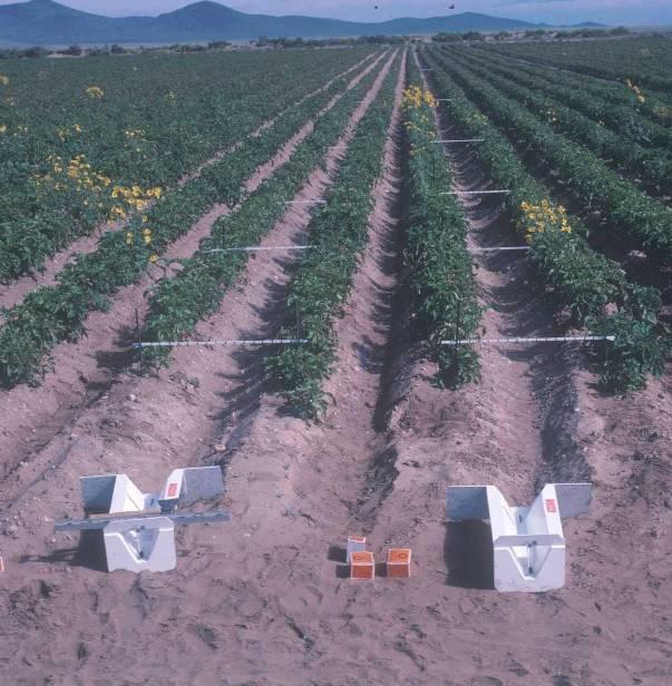
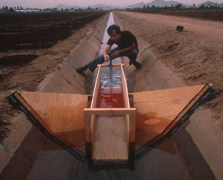
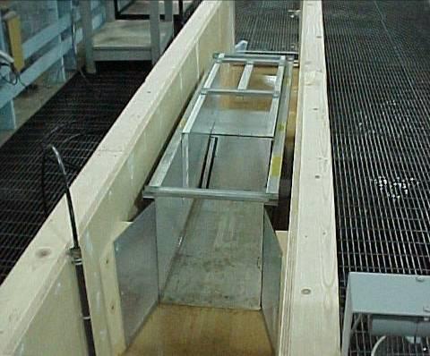
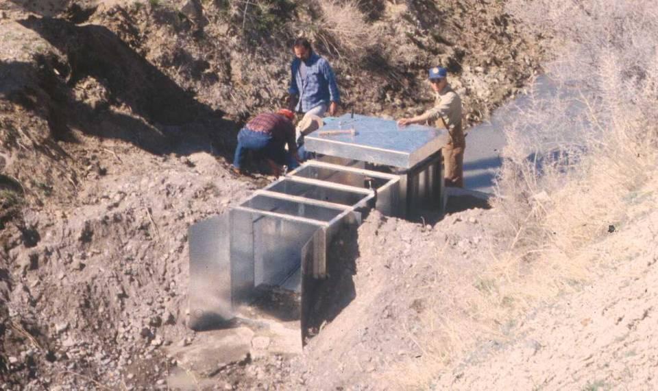
1 Transition Submergence and Hysteresis Effects in Three-Foot Cutthroat Flumes
2 Why Measure Water for Irrigation? (You had to ask.) Improve: Accuracy Convenience Economics
3 Water Measurement Manual (Door Prize) Published by Reclamation in 1997
4 Small mistakes at the beginning can result in big errors at the end
5 Measuring Water Has Been Going on For a Long Time Older techniques may be simple, but effective for some purposes.
6 Goal: No Math in this Presentation! This is not possible.
7 Basic Open Channel Flow Measurement Q=AV Flow Rate = Area of flow multiplied by the (average) velocity of the flow. e.g. Channel with a cross section of 10 ft 2 and water traveling at 2 feet per second
8 At its simplest Use a buoyant object An orange Multiply velocity of float by a coefficient e.g Depth of water is 3 feet: 0.70 Depth of water is 12 feet: 0.78 More values are available Multiple floats
9 More better Find the average velocity in a stream 60% of the way from the water surface to the bottom
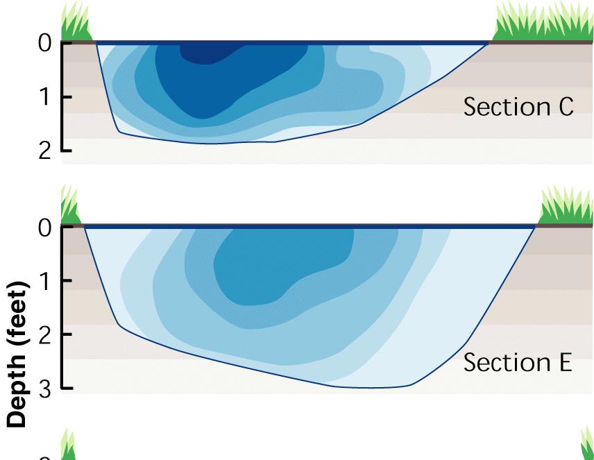
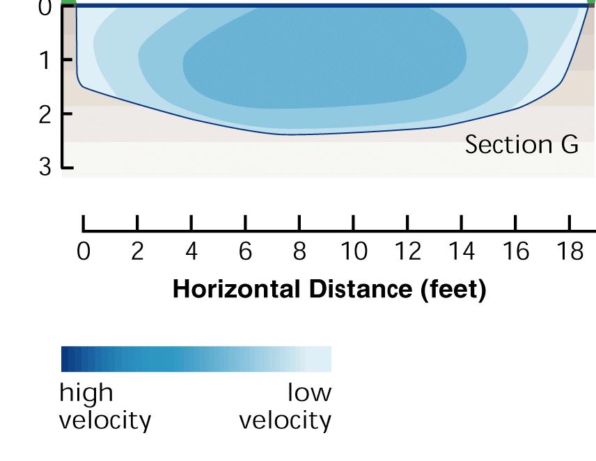
10 Best Check the velocity everywhere (or at more than 1 point)
11 Velocity Distributions Depth Relative roughness determines the distribution shape Velocity (avg)
12 Velocity With Stage
13
14 So how do you measure velocity? Show Flash Show wmv

15 Bernouilli s Principle Bernouilli says there are three forms of energy in water: Elevation head Pressure head Velocity head

16 Think of a swimming pool
17 Everything you need to know is in this slide (but the font is too small) NEH Flow measurement is based on specific predetermined hydraulic concepts. Measurement accuracy is strongly influenced by adherence to these concepts. For open channel weirs and flumes, water must pass through critical depth or two flow depths must be measured. With closed conduits the pipeline must be flowing full at the measuring device. This can be accomplished by dropping the pipeline below the hydraulic grade line.
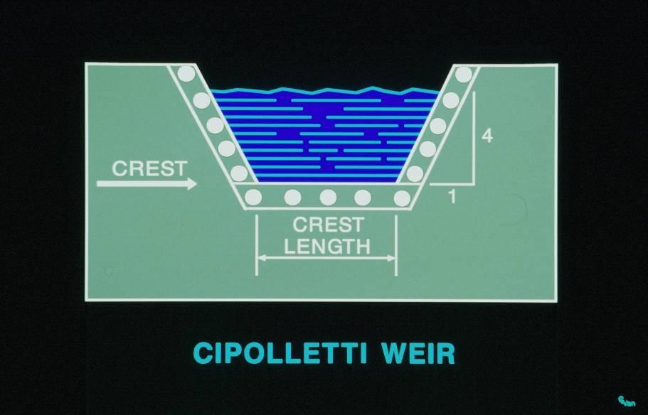
18 Reclamation Video 4 types of measuring devices Cipolletti Weir Yakima Box Submerged Orifice Ramp Flume
19 Weirs and Flumes Weirs and flumes work on the principle that the flow over the weir or flume must go through the critical depth. It is the height of a weir or flume that determines whether or not the flow goes critical.
20 Critical-Flow Measurement Devices Flumes, sharp-crested weirs, broadcrested weirs
21 Critical Depth And why it is important in measuring flow rates

22 Subcritical Critical Supercritical Hydraulic Jump Tim McCabe, IA NRCS Subcritical

23 Subcritical Critical Supercritical Hydraulic Jump Subcritical Lynn Betts, IA NRCS
24 Hydraulic Jump Change from supercritical to subcritical Typical below dams or obstructions Very high-energy loss/dissipation Difficult to predict location Water surface jumps up
25 Subcritical or Supercritical Direction of Flow Waves Travel Upstream Point of entry of the Stone First Wave Second Wave Third Wave Waves Travel Downstream (a) Sub-Critical Flow (b) Critical Flow (c) Super-Critical Flow
26
27 Flumes and Weirs This difference in elevation of the flow upstream from the structure with and without the flume or weir in place is the headloss caused by the device. Flumes tend to have less headloss than weirs
28 Critical-Flow Measurement Devices Produce critical-depth flow in a control section Critical depth occurs at locations where the downstream depth does not hold the flow back Minimum specific energy for a given flow Shallow-water waves cannot travel upstream Tailwater does not affect headwater elevation Flow rate through the critical section is a function of the upstream head, acceleration of gravity, and the control section size
29 Long-Throated Flumes and Broad-Crested Weirs Long-throated flumes with a streamlined converging transition have one-dimensional flow in the control section -- Long-throated means the throat is long enough to eliminate lateral and vertical contraction of the flow at the control section, so streamlines are essentially parallel to one another
30 Long-Throated Flumes and Broad-Crested Weirs Can be calibrated using well-established hydraulic theory No laboratory testing needed Calculations are iterative, but computer models that do the calculations have made long-throated flumes reasonable to implement in recent years
31 Traditional Critical-Flow Devices Most critical-flow devices have curvilinear, three-dimensional flow fields in the control section All such devices require laboratory calibration Flumes Parshall flumes, cutthroat flumes, H-flumes, etc. Sharp-Crested Weirs V-notch weirs, Cipoletti weirs, contracted and suppressed rectangular weirs, etc. Broad-Crested Weirs If they do not have a streamlined approach
32 Flumes and Weirs Permanent or portable installation Can be very accurate They are obstructions that produce backwater that extends upstream and raises the water surface in the approach channel
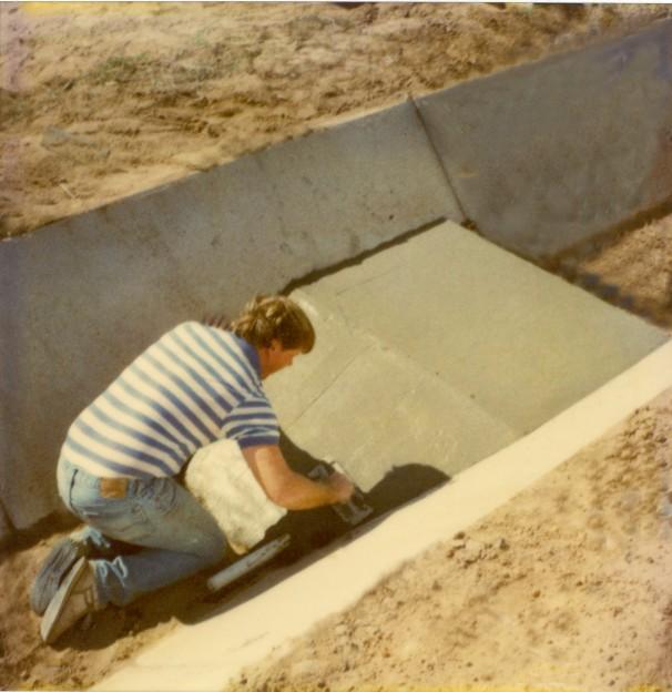
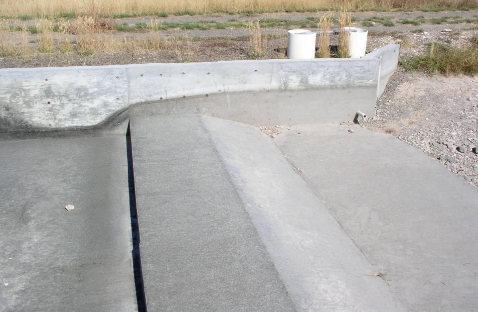
33 Ramp Flumes Also Known As Replogle Flume Long Throated Flume Broad Crested Weir
34
35
36
37
38
39
40
41
42
43
44
45
46 Transition Submergence and Hysteresis Effects in Three-Foot Cutthroat Flumes
47 WINFLUME
48

49 Weirs The importance of an aerated nappe
50
51
52
53 WEIR CONCERNS Debris on crest intuitive and obvious Approach conditions and sediment buildup Head measurement location avoid measuring in the drawdown zone Submergence on the downstream side
54 Drop a ball Velocity = 2gh
55 Submerged Orifice Q=AV But the area is not what you might expect

56 Orifice Meter
57 Did I mention there s a test?
HYDRAULIC JUMP AND WEIR FLOW
 HYDRAULIC JUMP AND WEIR FLOW 1 Condition for formation of hydraulic jump When depth of flow is forced to change from a supercritical depth to a subcritical depth Or Froude number decreases from greater
Simple Flow Measurement Devices for Open Channels
 Simple Flow Measurement Devices for Open Channels Seth Davis, Graduate Student deedz@nmsu.edu Zohrab Samani, Foreman Professor zsamani@nmsu.edu Civil Engineering Department, New Mexico State University
APPLICATION NOTE. AN-9608 July 2001 SEEPAGE MEASUREMENT IN AN OPEN CHANNEL THROUGH A WEIR
 APPLICATION NOTE AN-9608 July 2001 SEEPAGE MEASUREMENT IN AN OPEN CHANNEL THROUGH A WEIR 1 Introduction Seepage of water through, around or under a dam is expected in all embankment dams and even in concrete
SUBMERGED VENTURI FLUME. Tom Gill 1 Robert Einhellig 2 ABSTRACT
 SUBMERGED VENTURI FLUME Tom Gill 1 Robert Einhellig 2 ABSTRACT Improvement in canal operating efficiency begins with establishing the ability to measure flow at key points in the delivery system. The lack
Broadly speaking, there are four different types of structures, each with its own particular function:
 3 The selection of structures 3.1 Introduction In selecting a suitable structure to measure or regulate the flow rate in open channels, all demands that will be made upon the structure should be listed.
2O-2 Open Channel Flow
 Iowa Stormwater Management Manual O- O- Open Channel Flow A. Introduction The beginning of any channel design or modification is to understand the hydraulics of the stream. The procedures for performing
ANSWERS TO QUESTIONS IN THE NOTES AUTUMN 2018
 ANSWERS TO QUESTIONS IN THE NOTES AUTUMN 2018 Section 1.2 Example. The discharge in a channel with bottom width 3 m is 12 m 3 s 1. If Manning s n is 0.013 m -1/3 s and the streamwise slope is 1 in 200,
3. GRADUALLY-VARIED FLOW (GVF) AUTUMN 2018
 AUTUMN 2018") 3. GRADUALLY-VARIED FLOW (GVF) AUTUMN 2018 3.1 Normal Flow vs Gradually-Varied Flow V 2 /2g EGL (energy grade line) Friction slope S f h Geometric slope S 0 In flow the downslope component of weight balances
3. GRADUALLY-VARIED FLOW (GVF) AUTUMN 2018 3.1 Normal Flow vs Gradually-Varied Flow V 2 /2g EGL (energy grade line) Friction slope S f h Geometric slope S 0 In flow the downslope component of weight balances
Advanced Hydraulics Prof. Dr. Suresh A. Kartha Department of Civil Engineering Indian Institute of Technology, Guwahati
 Advanced Hydraulics Prof. Dr. Suresh A. Kartha Department of Civil Engineering Indian Institute of Technology, Guwahati Module - 4 Hydraulic Jumps Lecture - 1 Rapidly Varied Flow- Introduction Welcome
Effects of Submergence in Montana Flumes
 Utah State University DigitalCommons@USU All Graduate Theses and Dissertations Graduate Studies 5-2010 Effects of Submergence in Montana Flumes Ryan P. Willeitner Utah State University Follow this and
HY-8 Version 7.2 Build Date January 17, Federal Highway Administration.
 HY-8 Version 7.2 Build Date January 17, 2012 Federal Highway Administration http://www.fhwa.dot.gov/engineering/hydraulics/software/hy8/index.cfm SIMPLE Simple to use Use for simple culverts and bridges
EXAMPLES (OPEN-CHANNEL FLOW) AUTUMN 2018
 AUTUMN 2018") EXAMPLES (OPEN-CHANNEL FLOW) AUTUMN 2018 Normal and Critical Depths Q1. If the discharge in a channel of width 5 m is 20 m 3 s 1 and Manning s n is 0.02 m 1/3 s, find: (a) the normal depth and Froude number
EXAMPLES (OPEN-CHANNEL FLOW) AUTUMN 2018 Normal and Critical Depths Q1. If the discharge in a channel of width 5 m is 20 m 3 s 1 and Manning s n is 0.02 m 1/3 s, find: (a) the normal depth and Froude number
RBC flume. All it takes for environmental research. Contents. 1. Introduction. 2. The flumes of Eijkelkamp Agrisearch Equipment
 13.17.06 RBC flume operating instructions Contents 1. Introduction... 1 2. The flumes of Eijkelkamp Agrisearch Equipment... 1 3. Principles of discharge-measuring flumes... 2 4. Selection and location
2. RAPIDLY-VARIED FLOW (RVF) AUTUMN 2018
 AUTUMN 2018") 2. RAPIDLY-VARIED FLOW (RVF) AUTUMN 2018 Rapidly-varied flow is a significant change in water depth over a short distance (a few times water depth). It occurs where there is a local disturbance to the
2. RAPIDLY-VARIED FLOW (RVF) AUTUMN 2018 Rapidly-varied flow is a significant change in water depth over a short distance (a few times water depth). It occurs where there is a local disturbance to the
OPEN CHANNEL FLOW WORKSHEET 3 WATER SURFACE PROFILES
 Learning Objectives OPEN CHANNEL FLOW WORKSHEET 3 WATER SURFACE PROFILES 1. Learn about gradually varied flow and rapidly varying flow 2. Discuss different types of water surface profiles 3. Discuss the
Grit chambers are basin to remove the inorganic particles to prevent damage to the pumps, and to prevent their accumulation in sludge digestors.
 Home Lecture Quiz Design Example Grit Chambers Types of Grit Chambers Aerated Grit Chamber Principle of Working of Grit Chamber Design of Grit Chambers Primary Sedimentation Grit Chambers Grit chambers
FREE OVERFALL IN A HORIZONTAL SMOOTH RECTANGULAR CHANNEL
 International Journal of Civil Engineering and Technology (IJCIET) Volume 8, Issue 4, April 017, pp. 004 01, Article ID: IJCIET_08_04_8 Available online at http://www.iaeme.com/ijciet/issues.asp?jtype=ijciet&vtype=8&itype=4
Selecting Flow Metering Sites And Evaluating Data
 Insert Slide Title Here Selecting Flow Metering Sites And Evaluating Data Patrick L. Stevens, PE Luis Mijares PStevens2@Idexcorp.com LMijares@Idexcorp.com ADS Environmental Services Strategy for Selecting
Hours / 100 Marks Seat No.
 17421 15116 3 Hours / 100 Seat No. Instructions (1) All Questions are Compulsory. (2) Answer each next main Question on a new page. (3) Illustrate your answers with neat sketches wherever necessary. (4)
APPENDIX B HYDRAULIC DESIGN DATA FOR CULVERTS
 TM 5-820-4/AFM 88-5, Chap 4 APPENDIX B HYDRAULIC DESIGN DATA FOR CULVERTS B-1. General. a. This appendix presents diagrams, charts, coefficients and related information useful in design of culverts. The
D emonstration of Possible F low Conditions in a Culvert
 D emonstration of Possible F low Conditions in a Culvert M. R. CARSTENS, Associate Professor, Georgia Institute of Technology and A. R. HOLT, Lt. U.S. Army Corps of Engineers, Fort Belvoir, Virginia e
Advanced Hydraulics Prof. Dr. Suresh A. Kartha Department of Civil Engineering Indian Institute of Technology, Guwahati
 Advanced Hydraulics Prof. Dr. Suresh A. Kartha Department of Civil Engineering Indian Institute of Technology, Guwahati Module - 4 Hydraulics Jumps Lecture - 4 Features of Hydraulic Jumps (Refer Slide
5.6 Flume Design Procedure
 5.6 Flume Design Procedure The intent of the design procedure is to determine the appropriate dimensions of a flow-measuring flume that will perform according to the criteria described in Section 5.2.
7 Flumes. 7.1 Long-throated flumes Description
 7 Flumes A critical depth-flume is essentially a geometrically specified constriction built in an open channel where sufficient fall is available for critical flow to occur in the throat of the flume.
CHAPTER 5 CULVERT DESIGN
 CHAPTER 5 CULVERT DESIGN HYDRAULICS OF CULVERTS There are two major types of culvert flow: 1) flow with inlet control, and 2) flow with outlet control. For each type, different factors and formulas are
Hydraulic Engineering
 PDHonline Course H146 (4 PDH) Hydraulic Engineering Instructor: Mohamed Elsanabary, Ph.D., Prov. Lic. Engineering. 2013 PDH Online PDH Center 5272 Meadow Estates Drive Fairfax, VA 22030-6658 Phone & Fax:
PENNDRAIN.rep. HEC-RAS Version May 2005 U.S. Army Corp of Engineers Hydrologic Engineering Center 609 Second Street Davis, California
 HEC-RAS Version 3.1.3 May 2005 U.S. Army Corp of Engineers Hydrologic Engineering Center 609 Second Street Davis, California X X XXXXXX XXXX XXXX XX XXXX X X X X X X X X X X X X X X X X X X X XXXXXXX XXXX
Effect of Fluid Density and Temperature on Discharge Coefficient of Ogee Spillways Using Physical Models
 RESEARCH ARTICLE Effect of Fluid Density and Temperature on Discharge Coefficient of Ogee Spillways Using Physical Models M. SREENIVASULU REDDY 1 DR Y. RAMALINGA REDDY 2 Assistant Professor, School of
Spillway Design for Small Dams
 Spillway Design for Small Dams by David E. Fantina, PE Introduction: This course presents an overview of the features that go into the design of spillways for small dams. Small dams in this course refer
CHAPTER 4 SPALDING COUNTY, GEORGIA 4.0 CULVERT DESIGN
 SPALDING COUNTY, GEORGIA CHAPTER 4 4.0 CULVERT DESIGN... 4-1 4.1 INTRODUCTION... 4-1 4.2 SYMBOLS AND DEFINITIONS... 4-1 4.3 ENGINEERING DESIGN CRITERIA... 4-2 4.3.1 FREQUENCY FLOOD... 4-2 4.3.2 VELOCITY
Experiment (13): Flow channel
: Flow channel") Experiment (13): Flow channel Introduction: An open channel is a duct in which the liquid flows with a free surface exposed to atmospheric pressure. Along the length of the duct, the pressure at the surface
Experiment (13): Flow channel Introduction: An open channel is a duct in which the liquid flows with a free surface exposed to atmospheric pressure. Along the length of the duct, the pressure at the surface
Rock Ramp Design Guidelines. David Mooney MS Chris Holmquist-Johnson MS Drew Baird Ph.D. P.E. Kent Collins P.E.
 Rock Ramp Design Guidelines David Mooney MS Chris Holmquist-Johnson MS Drew Baird Ph.D. P.E. Kent Collins P.E. Rock Ramp Design Guidelines OUTLINE Local and System Interactions with Rock Ramps Ramp Geometry
Evaluating the Spillway Capacity of the Morning Glory Spillway at Harriman Dam
 Evaluating the Spillway Capacity of the Morning Glory Spillway at Harriman Dam Damian M. Gomez, P.E., CFM, Gomez and Sullivan Engineers, D.P.C. Dan Gessler, Ph.D., P.E., D.WRE, Alden Research Laboratory,
Culvert Design for Low and High Gradient Streams in the Midwest. Dale Higgins, Hydrologist Chequamegon-Nicolet National Forest
 Culvert Design for Low and High Gradient Streams in the Midwest Dale Higgins, Hydrologist Chequamegon-Nicolet National Forest Overview Culvert Design Considerations Hydraulic Terms Culvert Impacts Low
General Information for Culvert Design
 Design Manual Chapter 2 - Stormwater 2E - Culvert Design 2E-1 General Information for Culvert Design A. Introduction A culvert is a conduit under an embankment that transports stormwater from one side
FSOC Upstream Fish Passage Guidance Document
 FSOC Upstream Fish Passage Guidance Document STEP 1: Identify species and life stages in need of fish passage STEP 2: Identify fishway options and species applicability STEP 3 Fish passage criteria review
STRUCTURE S-65 PURPOSE SPILLWAY OPERATION
 STRUCTURE S-65 This structure is a reinforced concrete, gated spillway with discharge controlled by three cable operated, vertical lift gates, and a reinforced concrete lock structure with two pairs of
Measuring Water with Parshall Flumes
 Utah State University DigitalCommons@USU Reports Utah Water Research Laboratory January 1966 Measuring Water with Parshall Flumes Gaylord V. Skogerboe M. Leon Hyatt Joe D. England J. Raymond Johnson Follow
Flowmeter Shootout Part II: Traditional Technologies
 Flowmeter Shootout Part II: Traditional Technologies How to Choose Among Turbine, Positive Displacement, Thermal, Variable Area, and Open Channel Using Paradigm Cases By Jesse Yoder February 22, 2001 This
Modelling of Pressurised Pipes within InfoWorks ICM and CS
 Modelling of Pressurised Pipes within InfoWorks ICM and CS 1. Introduction Correctly modelling pressurised pipes, variously described as forcemains or rising mains, can be one of the more difficult aspects
Sediment Basin 7E-12. Design Manual Chapter 7 - Erosion and Sediment Control 7E - Design Information for ESC Measures BENEFITS.
 7E-12 Design Manual Chapter 7 - Erosion and Sediment Control 7E - Design Information for ESC Measures Sediment Basin BENEFITS Flow Control Erosion Control Sediment Control Runoff Reduction Flow Diversion
Fluid Mechanics-I Laboratory Manual
 2014 Fluid Mechanics-I Laboratory Manual Prepared by: Mr. Avijit Paul Approved by: Dr. Arabinda sharma Civil Engineering Department BRCM College of Engg & Technology Bahal-127 028, Bhiwani Haryana LIST
Indiana LTAP Road Scholar Core Course #10 Culvert Drainage. Presented by Thomas T. Burke, Jr., PhD, PE Christopher B. Burke Engineering, Ltd.
 Indiana LTAP Road Scholar Core Course #10 Culvert Drainage Presented by Thomas T. Burke, Jr., PhD, PE Christopher B. Burke Engineering, Ltd. Objectives Review culvert shapes, end sections, and materials
APPENDIX A STRUCTURE DESCRIPTIONS AND RATING CURVES
 3 4 5 6 7 8 9 0 3 APPENDIX A STRUCTURE DESCRIPTIONS AND RATING CURVES Kissimmee River Vol December 005 Version Draft 4 3 4 5 6 7 8 9 0 3 4 5 6 7 8 9 0 3 4 5 6 7 8 9 30 3 3 33 34 35 36 37 38 39 40 4 4 43
Exercise (4): Open Channel Flow - Gradually Varied Flow
: Open Channel Flow - Gradually Varied Flow") Exercise (4): Open Channel Flow - Gradually Varied Flow 1) A wide channel consists of three long reaches and has two gates located midway of the first and last reaches. The bed slopes for the three reaches
Exercise (4): Open Channel Flow - Gradually Varied Flow 1) A wide channel consists of three long reaches and has two gates located midway of the first and last reaches. The bed slopes for the three reaches
Transactions on Ecology and the Environment vol 12, 1996 WIT Press, ISSN
 Open boundary condition for unsteady open-channel flow K. Mizumura Civil Engineering Department, Kanazawa Institute of Technology, 7-1 Ogigaoka, Nonoichimachi, Ishikawa Pref. 921, Japan Abstract Initial
TOP:001.3 U.S. Fish and Wildlife Service TECHNICAL OPERATING PROCEDURE
 TOP:001.3 March 12, 2015 U.S. Fish and Wildlife Service Marquette Biological Station 3090 Wright Street Marquette, Michigan 49855 U.S.A. and U.S. Fish and Wildlife Service Ludington Biological Station
Exercise (3): Open Channel Flow Rapidly Varied Flow
: Open Channel Flow Rapidly Varied Flow") Exercise (3): Open Channel Flow Rapidly Varied Flow 1) A hydraulic jump exists in a trapezoidal channel having a bed width of 7 m and side slope of 1:1. The flowing discharge is 25 m 3 /sec. Construct
Exercise (3): Open Channel Flow Rapidly Varied Flow 1) A hydraulic jump exists in a trapezoidal channel having a bed width of 7 m and side slope of 1:1. The flowing discharge is 25 m 3 /sec. Construct
Folsom Dam Joint Federal Project Existing Spillway Modeling
 Hydraulic Laboratory Report HL-2009-02 Folsom Dam Joint Federal Project Existing Spillway Modeling Discharge Capacity Studies AMERICAN RIVER DIVISION CENTRAL VALLEY PROJECT MID-PACIFIC REGION U.S. Department
IMPACT OF MAKING THE CREST OF WEIR MULTIFACETED ON DISCHARGE COEFFICIENT OF MORNING GLORY SPILLWAY
 IMPACT OF MAKING THE CREST OF WEIR MULTIFACETED ON DISCHARGE COEFFICIENT OF MORNING GLORY SPILLWAY Ali Bagheri 1 and *Ebrahim Nohani 2 1 Department of Water Engineering, Qaemshahr Branch, Islamic Azad
DESIGN OF BELL-MOUTH SPILLWAY AT BARVI DAM
 DESIGN OF BELL-MOUTH SPILLWAY AT BARVI DAM Akshay Haldankar 1, Mahesh Bhadra 2, Rahul Harad 3, Darpan Kapre 4, Dipali Patil 5 1,2,3,4 Under graduate,dept. of Civil Engineering, DRIEMS Neral. 5Assistant
MODELLING ANCILLARIES: WEIR COEFFICIENTS
 WaPUG USER NOTE No 27 MODELLING ANCILLARIES: WEIR COEFFICIENTS David Balmforth, MWH 1. SCOPE This user note gives advice on the choice of coefficient for overflo eirs and orifices hen modelling storm seage
Effect of channel slope on flow characteristics of undular hydraulic jumps
 River Basin Management III 33 Effect of channel slope on flow characteristics of undular hydraulic jumps H. Gotoh, Y. Yasuda & I. Ohtsu Department of Civil Engineering, College of Science and Technology,
WASHINGTON CONSERVATION DISTRICT STANDARD OPERATING PROCEDURE (S.O.P.)
") Page 1 of 18 Water Monitoring Program WASHINGTON CONSERVATION DISTRICT STANDARD OPERATING PROCEDURE (S.O.P.) No. 1 FLOW MONITORING Page 2 of 18 Water Monitoring Program Standard Operating Procedure No.
Page 1 of 18 Water Monitoring Program WASHINGTON CONSERVATION DISTRICT STANDARD OPERATING PROCEDURE (S.O.P.) No. 1 FLOW MONITORING Page 2 of 18 Water Monitoring Program Standard Operating Procedure No.
Culvert Design Basics
 PDHonline Course C287 (4 PDH) Culvert Design Basics Instructor: George E. Thomas, PE 2012 PDH Online PDH Center 5272 Meadow Estates Drive Fairfax, VA 22030-6658 Phone & Fax: 703-988-0088 www.pdhonline.org
OFFICE OF STRUCTURES MANUAL FOR HYDROLOGIC AND HYDRAULIC DESIGN CHAPTER 11 APPENDIX B TIDEROUT 2 USERS MANUAL
 OFFICE OF STRUCTURES MANUAL FOR HYDROLOGIC AND HYDRAULIC DESIGN CHAPTER 11 APPENDIX B TIDEROUT 2 USERS MANUAL APRIL 2011 APRIL 2011 Page 1 Preface TIDEROUT 2, Build 1.22 dated June 29, 2006 is the current
Section 5: Pond Outlets
 Section : Pond Outlets Defining and calculating pond outlet devices 8 Minutes Press Space, PageDown, or Click to advance. Press PageUp to reverse. Esc to exit. Right-Click for other options. Outlets Introduction
Design and Calibration of Submerged Open Channel Flow Measurement Structures: Part 4 - Weirs
 Utah State University DigitalCommons@USU Reports Utah Water Research Laboratory 1-1-1967 Design and Calibration of Submerged Open Channel Flow Measurement Structures: Part 4 - Weirs Gaylord V. Skogerboe
Spillway with improved dissipation efficiency - side dissipation beams
 Spillway with improved dissipation efficiency - side dissipation beams Dušan Ciuha Jurij Mlanik IBE, Consulting Engineers Institute for Hydraulic Research Hajdrihova 4 Hajdrihova 28 Ljubljana Ljubljana
STRUCTURE 65-B PURPOSE SPILLWAY OPERATION
 STRUCTURE 65-B This structure is a reinforced concrete, gated spillway with discharge controlled by three cable operated vertical lift gates and a reinforced concrete lock structure with two pairs of sector
Evaluating Surge Potential in CSO Tunnels
 14 Evaluating Surge Potential in CSO Tunnels Karen E. Ridgway Tunnels are being proposed to control combined sewer overflow (CSO) in numerous cities in the United States and Canada. The tunnels are intended
SUPERCRITICAL FLOW AT AN ABRUPT DROP : FLOW PATTERNS AND AERATION
 SUPERCRITICAL FLOW AT AN ABRUPT DROP : FLOW PATTERNS AND AERATION by H. Chanson, Senior Lecturer, and L. Toombes, Ph.D. student Dept. of Civil Engineering, The University of Queensland, Brisbane QLD 4072,
6.6 Gradually Varied Flow
 6.6 Gradually Varied Flow Non-uniform flow is a flow for which the depth of flow is varied. This varied flow can be either Gradually varied flow (GVF) or Rapidly varied flow (RVF). uch situations occur
FORMAT FOR SENDING COMMENTS. Title: CRITERIA FOR DESIGN OF CANAL HEAD REGULATORS (Second revision of IS 6531)
") FORMAT FOR SENDING COMMENTS Last Date for Comment is 0 November 009 E-Mail ID for sending comments: rrdash@bis.org.in Document No.: Doc WRD 14 (495)C Title: CRITERIA FOR DESIGN OF CANAL HEAD REGULATORS
FORMAT FOR SENDING COMMENTS Last Date for Comment is 0 November 009 E-Mail ID for sending comments: rrdash@bis.org.in Document No.: Doc WRD 14 (495)C Title: CRITERIA FOR DESIGN OF CANAL HEAD REGULATORS
BC Ministry of Forests. March Fish Stream Crossing Guidebook. Forest Practices Code of British Columbia.
 FRST 557 Lecture 7c Bridges and Culverts: Water Velocity and Discharge Lesson Background and Overview: The previous two lessons presented methods for estimating water volume flow at a particular site and
Designing Labyrinth Spillways for Less than Ideal Conditions Real World Application of Laboratory Design Methods
 Designing Labyrinth Spillways for Less than Ideal Conditions Real World Application of Laboratory Design Methods Gregory Richards, P.E., CFM, Gannett Fleming, Inc. Blake Tullis, Ph.D., Utah Water Research
Annex C Temporary Fish Passage Plan
 Annex C Temporary Fish Passage Plan Table C1 Figure C1 Figure C2 Figure C3 Figure C4 Figure C5 Figure C6 Figure C7 Figure C8 Figure C9 Figure C10 Figure C11 Figure C12 Figure C13 Options Considered in
USING A LABYRINTH WEIR TO INCREASE HYDRAULIC CAPACITY. Dustin Mortensen, P.E. 1 Jake Eckersley, P.E. 1
 USING A LABYRINTH WEIR TO INCREASE HYDRAULIC CAPACITY Dustin Mortensen, P.E. 1 Jake Eckersley, P.E. 1 Plum Creek Floodwater Retarding Structure No. 6 is located in an area of Kyle, Texas, that is currently
Impact of anti-vortex blade position on discharge experimental study on the coefficient of morning glory spillway
 Journal of Scientific Research and Development (7): 91-95, 015 Available online at www.jsrad.org ISSN 1115-7569 015 JSRAD Impact of anti-vortex blade position on discharge experimental study on the coefficient
AIR-WATER FLOW STRUCTURES AT AN ABRUPT DROP WITH SUPERCRITICAL FLOW
 AIR-WATER FLOW STRUCTURES AT AN ABRUPT DROP WITH SUPERCRITICAL FLOW H. CHANSON and L. TOOMBES Department of Civil Engineering, The University of Queensland, Brisbane QLD 4072, Australia 1. Introduction
19.1 Problem: Maximum Discharge
 19.1 Problem: Maximum Discharge In partially full channel having an equilateral triangular cross section, the rate of discharge is Q = KAR/3 in which K is a constant, A flow area, R is the hydraulic mean
Wave Load Pattern Definition
 COMPUTERS AND STRUCTURES, INC., AUGUST 2010 AUTOMATIC WAVE LOADS TECHNICAL NOTE DEFINING WAVE LOADS This section describes how to define automatic wave loads. The automatic wave load is a special type
Using sea bed roughness as a wave energy dissipater
 Island Sustainability II 203 Using sea bed roughness as a wave energy dissipater T. Elgohary 1, R. Elgohary 1 & M. Hagrass 2 1 Department of Civil Engineering (Irrigation and Hydraulic), The Tenth of Ramadan
Plan B Dam Breach Assessment
 Plan B Dam Breach Assessment Introduction In support of the Local Sponsor permit applications to the states of Minnesota and North Dakota, a dam breach analysis for the Plan B alignment of the Fargo-Moorhead
The Basics of Culvert and Inlet Design
 PDHonline Course C619 (8 PDH) The Basics of Culvert and Inlet Design Jerry D. Morrow, PE 2013 PDH Online PDH Center 5272 Meadow Estates Drive Fairfax, VA 22030 6658 Phone & Fax: 703 988 0088 www.pdhonline.org
Hours / 100 Marks Seat No.
 17421 21415 3 Hours / 100 Marks Seat No. Instructions : (1) All Questions are compulsory. (2) Answer each next main Question on a new page. (3) Illustrate your answers with neat sketches wherever necessary.
Culvert Hydraulics: Comparison of Current Computer Models
 Brigham Young University BYU ScholarsArchive All Theses and Dissertations 2007-03-13 Culvert Hydraulics: Comparison of Current Computer Models Elizabeth Anne Thiele Brigham Young University - Provo Follow
InstrumentationTools.com
 Author: Instrumentation Tools Categories: F Measurement Fmeter Characteristics Experts claim that over 75 percent of the fmeters installed in industry are not performing satisfactorily. And improper selection
CEE 345, Part 2, Winter 2012, Final Exam Solutions (Open Channel Flow)
") CEE 45, Part, Winter 0, Final Exam Solutions (Open Channel Flow). (a) (8) List and briefl describe the forces that must be considered in an analsis of flow in a trapezoidal channel with a slope of 0.006.
CEE 45, Part, Winter 0, Final Exam Solutions (Open Channel Flow). (a) (8) List and briefl describe the forces that must be considered in an analsis of flow in a trapezoidal channel with a slope of 0.006.
Habitat Conditions, Design Strategies,
 Habitat Conditions, Design Strategies, Coho on Cedar Ck. five years after analog-based stream restoration work. and Stream Classification In river work, computer modeling is an insidious procedure in which
THE IMPROVED VENTURI FLUME
 THE IMPROVED VENTURI FLUME By RALPH L. PARSHALL, Irrigation Engineer Prepared under the direction of W. W. McLaughlin, Associate Chief, Division of Agricultural Engineering, United States Depar-tment of
Khosla's theory. After studying a lot of dam failure constructed based on Bligh s theory, Khosla came out with the following;
 Khosla's theory After studying a lot of dam failure constructed based on Bligh s theory, Khosla came out with the following; Following are some of the main points from Khosla's Theory From observation
Balancing HVAC Hydronic Systems Part 3: Flow Measurement Valves
 Balancing HVAC Hydronic Systems Part 3: Flow Measurement Valves Monday Morning Minutes by Norm Hall, August 20, 2018 The flow balance of a hydronic system is a critical component in the commissioning of
Storm Damage Floating Culverts & Other Inlet Issues
 Storm Damage Floating Culverts & Other Inlet Issues Mark Bailey, PE - Hydraulic Manager, INDOT Dale Sedler, PE - Sr. Hydraulic Engineer, INDOT Road School 2016 What causes a culvert to float? 1. Accumulation
Experiment Instructions
 Experiment Instructions Syphon Spillway Experiment Instructions Please read and follow the instructions before the first installation! Publication-no.: 917.000 36 A 160 02 (A) 01/2000, (DTP_2), 05/1999
Chapter 9 System Design Procedures
 Chapter 9 CHAPTER 9 SYSTEM DESIGN PROCEDURES TABLE OF CONTENTS PART 9.1 GENERAL 9-1 PART 9.2 EXAMPLE 1, LOW PRESSURE GRAVITY SYSTEM 9-1 PART 9.3 EXAMPLE 2, PUMPED AUTOMATIC PRESSURE PIPELINE 9-4 9.3.1
3D NUMERICAL MODELLING OF THE CAPACITY FOR A PARTIALLY PRESSURIZED SPILLWAY
 3D NUMERICAL MODELLING OF THE CAPACITY FOR A PARTIALLY PRESSURIZED SPILLWAY Samuel Vingerhagen 1 & Nils Reidar B. Olsen 1 1 Department of Hydraulic and Environmental Engineering, The Norwegian Univeristy
Total Dissolved Gas Properties and Processes. by Mike Schneider US Army Corps of Engineers Engineer Research and Development Center
 Total Dissolved Gas Properties and Processes by Mike Schneider US Army Corps of Engineers Engineer Research and Development Center TDG Properties and Processes Scope of Discussion Physical Properties of
4.3 Oblique Shocks and Expansions Fans: The Supercritical Marine Layer.
 4.3 Oblique Shocks and Expansions Fans: The Supercritical Marine Layer. The marine layer is a relatively dense and well-mixed layer of moist air that lies above the sea surface and is often capped by a
Lecture 10 : Sewer Appurtenances
 1 P age Module 8 : Sewer Appurtenances Lecture 10 : Sewer Appurtenances 2 P age The structures, which are constructed at suitable intervals along the sewerage system to help its efficient operation and
CHAPTER 68. RANDOM BREAKING WAVES HORIZONTAL SEABED 2 HANS PETER RIEDEl. & ANTHONY PAUL BYRNE
 CHAPTER 68 RANDOM BREAKING WAVES HORIZONTAL SEABED 2 HANS PETER RIEDEl. & ANTHONY PAUL BYRNE ABSTRACT According to wave theories the depth limited wave height over a horizontal seabed has a wave height
Structure and discharge test cases
 Chapter 28 Structure and discharge test cases 28.1 Introduction Three test case have been implemented to test the performance and applicability of the structures and discharges modules. drythin Simulates
The Hydraulic Design of an Arced Labyrinth Weir at Isabella Dam
 Utah State University DigitalCommons@USU International Symposium on Hydraulic Structures Jun 28th, 1:30 PM The Hydraulic Design of an Arced Labyrinth Weir at Isabella Dam E. A. Thompson Sacramento District
Greenup Lock Filling and Emptying System Study
 Fourth LACCEI International Latin American and Caribbean Conference for Engineering and Technology (LACCET 2006) Breaking Frontiers and Barriers in Engineering: Education, Research and Practice 21-23 June
FLOW MEASUREMENT (SEMI-SUBMERGIBLE OBJECT METHOD)
") Page 83 of 232 OKLAHOMA CONSERVATION COMMISSION WATER QUALITY DIVISION STANDARD OPERATING PROCEDURE FLOW MEASUREMENT (SEMI-SUBMERGIBLE OBJECT METHOD) Page 84 of 232 1.0 PROCEDURAL SECTION 1.1 Scope and
Page 83 of 232 OKLAHOMA CONSERVATION COMMISSION WATER QUALITY DIVISION STANDARD OPERATING PROCEDURE FLOW MEASUREMENT (SEMI-SUBMERGIBLE OBJECT METHOD) Page 84 of 232 1.0 PROCEDURAL SECTION 1.1 Scope and
Introduction to Check Dams
 Introduction to Check Dams Kabul, Afghanistan February 2011 3 This watershed rehabilitation and restoration training was prepared by the U.S. Department of Agriculture (USDA) team of Jon Fripp (Civil Engineer
Annex E Bridge Pier Protection Plan
 Annex E Bridge Pier Protection Plan Table E1 Bridge Types and Locations Table E2 Flow Conditions For River Sections Figure E1 Bridge Abutment Protection Figure E2 Bridge Pier Protection Figure E3 Central
Lab 1: Pressure and surface tension. Bubblers, gravity and the mighty paper clip.
 Lab 1: Pressure and surface tension. Bubblers, gravity and the mighty paper clip. CEE 3310 - Summer 2012 SAFETY The major safety hazard in this laboratory is a shock hazard. Given that you will be working
TDLP INC. The Dam & Levee Professionals. Kevin Chancey Sarah Edens. Monica Murie Jason Unruh
 TDLP INC The Dam & Levee Professionals Kevin Chancey Sarah Edens Monica Murie Jason Unruh The Dam & Levee Professionals Prevention and Protection of Floodwall Overtopping Scour The Dam & Levee Professionals
COEFFICIENT OF DISCHARGE OF CHIMNEY WEIR UNDER FREE AND SUBMERGED FLOW CONDITIONS
 COEFFICIENT OF DISCHARGE OF CHIMNEY WEIR UNDER FREE AND SUBMERGED FLOW CONDITIONS Hanaa A.M.Hayawi Amal A.G.Yahya Ghania A.M.Hayawi College Of Engineering University Of Mosul Abstract: The main objective