Selecting Flow Metering Sites And Evaluating Data
|
|
|
- Bryce Egbert Gilmore
- 5 years ago
- Views:
Transcription

1 Insert Slide Title Here Selecting Flow Metering Sites And Evaluating Data Patrick L. Stevens, PE Luis Mijares ADS Environmental Services
2 Strategy for Selecting & Evaluating Flow Metering Sites 1. Criteria for Site Selection 2. Understanding Metering Technology 3. Flow Meters Provide two types of information 4. Are the Data good? 5. What are data telling me about pipe hydraulics?
3 Ideal Site Hydraulics Clean manhole (silt, debris, grease, etc.) Straight & smooth flow One pipe in & one out preferred No drop connections Avoid Hydraulic Jumps

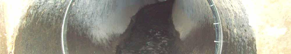
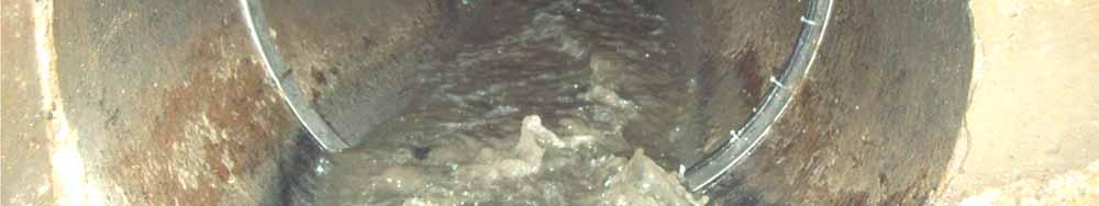
4 Physical Inspection is most common way to select or rule out bad metering site
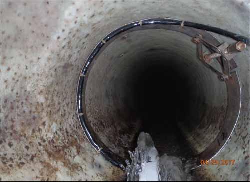
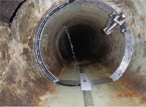
5 A B C D


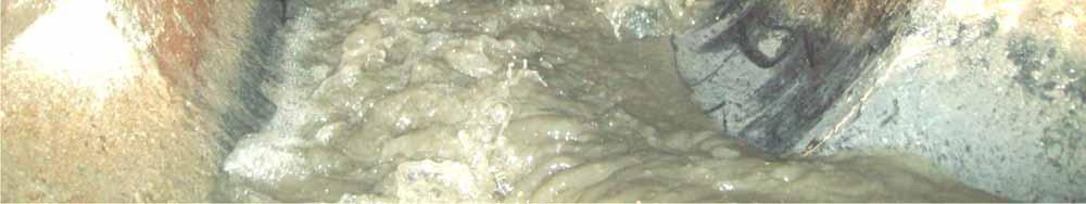
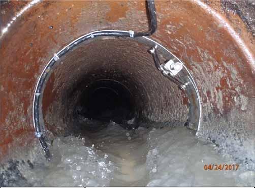
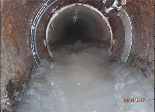
6 E F Let s take a look at Flow Metering Technology
7 No Flow Meter on the Face of the Earth Measures Flow Directly All meters measure some other physical entity and calculate flow rate. Flumes and Weirs measure only depth Open Channel Sewer Flow Meters measure Depth and Velocity. The Continuity Equation is used to Calculate Flow rate.
8 Open Channel Meters use Continuity Equation Flow Rate = Wetted Cross Sectional Area x Average Velocity 4" 3" Area of flow 2" 1" Depth

9 Typical Metering Installation Incoming Line Stable Hydraulics D & V measured in same place. Avoid Disturbances in MH Channel Far enough upstream to avoid drawdown
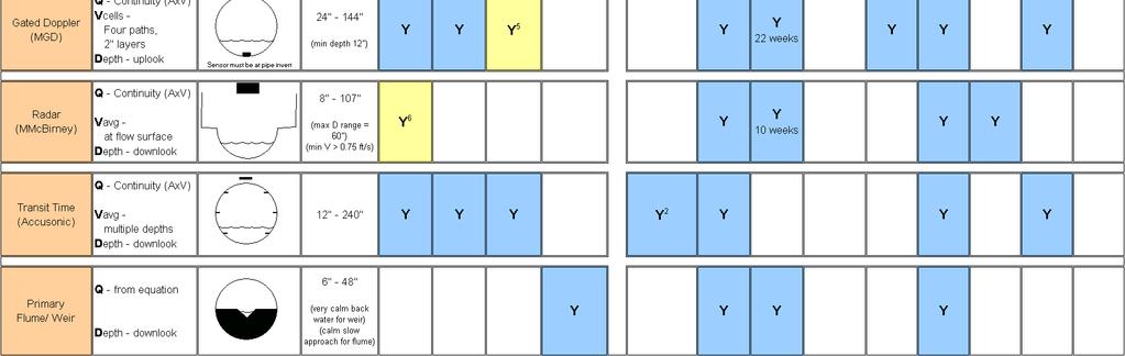
10 Open Channel Technologies Depth (only two) Pressure Sensor Ultrasonic Downlooker Ultrasonic Uplooker Velocity Average Doppler Peak Doppler Gated Doppler Travel Time Faraday Surface Doppler Radar Cross Correlation
11 Pressure Depth Sensor water
12 Pressure Depth Basic Operation The cable contains wires and an air tube that opens at the top of the manhole air Diaphragm with Strain Gauge water Port to Sewer Air vent tube The sensor contains a gauge to measure the pressure difference of the water and air The pressure sensor is typically mounted to the bottom of the pipe above any silt
13 Ultrasonic Depth Sensor water
14 Ultrasonic Depth Sensors Can be Uplooker or Downlooker Measures up to the Pipe Diameter Measurement Based on Time No Drift

15 Ultrasonic Down Looking Depth Sensor
16 Ultrasonic Up Looking Depth Sensor
17 Depth Sensor Technologies Offer Different Window of Precision Ultrasonic Depth Precision Pressure Depth Precision is based on a percentage of Full Scale Inches 4" 3" 2" 1" Ultrasonic Depth Pressure Depth M J J A gpm 0.2% of Full Scale (11.5') =0.28 inches
18 Velocity Technologies Cross Correlation ADS FlowShark Pulse Average Hach-Sigma 940 ISCO 2150 Continuous Wave Peak ADS FlowShark Doppler Surface Hach-MMB Flo-Dar Gated ISCO ADFM Electromagnetic Hach-MMB Flo-Tote Time of Transit Accusonic

19 Doppler Technology is Similar to Traffic Radar
20 Peak Combo Sensor During Full Pipe Pressure Depth Automatically Switches Pressure sensor previously calibrated Can be raised on block above silt level

21 This meter configuration is suitable for only those sites with a uniform slope through the manhole invert.

22 Types of Flow Monitors
23 Hydrograph Precision and Bias
24 Basin Flow and Prioritization Rain Flow (MGD) Basin Size Has Cost Leverage 02_34S Hydraulic Analysis = $4,000/meter, Physical Inspection = $2.5/LF & Rehab. = $ 7/LF $4,000 $3,500 $3,000 $2,500 $2,000 $1,500 $1,000 1 Mon Nov 2004 $500 $0 Rainfall Pipe Flow Qfinal(g) 385,000 LF 85,000 LF 31,000 LF 8,100 LF Hydraulic Analysis Physical Inspection Rehabilitation Total 8 Mon 15 Mon 22 Mon 1 Wed Date Rainfall (in)
25 In Uniform Flow Conditions this scattergraph is produced. The combination of a Manning Curve, meter data and confirmations reveal accurate meter in uniform flow.
26 Spotting Bad Velocity and Bad Depth
27 Possible Hydraulic Conditions At Flow Metering Sites A B C D E F A. Uniform Flow B. Transition to Backwater C. Within Backwater D. Supercritical Flow E. Hydraulic Jump F. Subcritical Flow
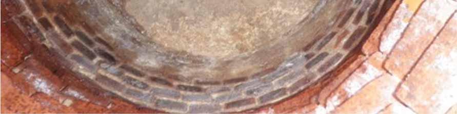
28 Dead Dog Silt Silt and Obstacles result in backwater at a meter.
29 Dead Dog The Stevens-Schutzbach method fits a Lanfear-Coll curve to the data and quantifies the Dead Dog. Dead Dog = 6.45 in.


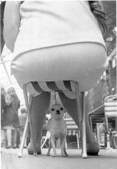

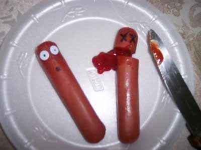
30 What is a Dead Dog?
31 High Technology proves the existence of the Dead Dog in sewers


32 This Junction Dogs could have resulted in the recommendation to clean the line.

33 Junction Dogs or Hydraulic Dead Dogs are created by downstream turning structures, junctions or poor outlet conditions from the manhole.
34 Regardless of the cause of a Downstream Dead Dog, flow approaching the velocity sensor becomes deeper and slower (a variable cross section). Where is Velocity measured by a Doppler sensor? Cross section gets smaller and velocity is higher. Meter Hump
35 The Offset Joint Dead Dog. Higher velocity is found as water spills over the offset joint. Velocity Will be affected by this flow. Depth measured here.


36 The Log Ride Dead Dog. Higher velocity is Found in the Log Ride zone.
37 The Log Ride Dead Dog. Higher velocity is Found in the Log Ride zone. Super Critical Flow Causes Log Ride Effect
38 Hydraulic Jump Fr = 0.7 Fr = 1.0 Fr = max min MGD 8 Flow Velocity (ft/s)

39 Undular Jump or Standing Waves MGD Fr = max Fr = MGD 5 min Fr = Flow Velocity (ft/s)
 3 2.5 2 1.5 1 0.")
 11 10 9 8 7 6 5 This stair step pattern formed by the few days of green data is the characteristic pattern of standing waves. 9 8 7 6 Iso Q (MGD) The Dead Dog of 4.")
40 KB_ Scatter Graph KB_04 Stevens-Schutzbach (C-SS = 5.48; d-dog = 0.77) Fr = 0.7 Fr = 1.5 Fr = 1.0 Fr = 1.5 Fr = VFINAL (ft/s) D dog of 0.8 inches suggests the cross sectional in the upper flow should be reduced by 0.8 inches DFINAL (in) Iso Q (MGD) KB_10 18 Scatter Graph KB_10 Lanfear-Coll (C-LC = 9.53) Stevens-Schutzbach (C-SS = 16.11; d-dog = 4.32) Fr = 0.7 Fr = 1.0 Fr = Log Ride effect from a steep incoming pipe. VFINAL (ft/s) This stair step pattern formed by the few days of green data is the characteristic pattern of standing waves Iso Q (MGD) The Dead Dog of 4.5 inches 4 is due to the Log Ride effect 3 from a steep incoming pipe DFINAL (in)
41 Scattergraphs can be used to define Four Types of hydraulic conditions & Dead Dogs Type 1 Super Critical Flow. No chance of Dead Dog or silt. Type 2 Hydraulic Jump passes through ring. The Zorro Z is the sign. Type 2A Standing Waves. Stair steps. Type 3 Log Ride Effect. Velocity in transition zone without a Zorro Z or standing waves. Type 4 Sub Critical Flow. Real Downstream Dead Dog. Could have silt.

42 Properly Deployed, a Flow Meter will see Upstream and Downstream (Double the information by looking at Scattergraphs) Dry Weather Flow Weekdays, Fridays and Weekends W eekdays W eekends Friday MGD Hours Upstream Downstream Depth - Velocity Flowmeter
43 Iso-Q Lines
44 In an ideal pipe, the pipe can surcharge and the Hydraulic Grade Line will be parallel to the pipe. In this situation the pipe should be carrying full capacity Hydraulic Grade Line Depth - Velocity Flowmeter
45 Surcharge By the Book
46 Bottleneck Downstream of Flowmeter HGL is Nearly Flat for Several MHs Upstream HGL Depth - Velocity Flowmeter ROOTS
47 Bottleneck & Capacity Loss Operational Capacity is 55%. Replacement or pipe bursting may be the solution here.
48 Upstream SSO SSO Upstream of Flowmeter Depth - Velocity Flowmeter ROOTS
49 Upstream SSO Operational Capacity is 50%. Replacement or pipe bursting may be the solution here. Signature of U/S SSO. (Cluster of data constant V constant D)
50 SSO and Bottleneck Downstream of Flowmeter Depth - Velocity Flowmeter ROOTS
51 Downstream SSO Operational Capacity is 50%. Replacement or pipe bursting may be the solution here. Signature of D/S SSO. (V increase at constant D) 51
52 Soft Restriction Roots create a restriction that does not follow an Iso-Q line.

53 Soft Restriction
54 Two Major Branches in Sewer. Intuitive meter locations here.

55 Two Major Branches in Sewer. Knowledge of Scattergraphs says to place one meter upstream of Double barrel siphon.
56 Scattergraph upstream of siphon reveals that it is a severe restriction and surcharged 7 feet. VFINAL (ft/s) Stevens-Schutzbach (C-SS = 2.65; d-dog = 3.40) Scatter Graph EN_04 Theoretical Capacity is ~ 2.1 mgd Operational Capacity is ~ 0.6 mgd 84 inches Inv ft DFINAL (in) Iso Q (MGD)
57 Scattergraph Poster
58 Conclusions 1. Physical inspection of sites is critical first step in site selection. 2. Select the appropriate technology 3. Review of scattergraphs after installation provides a second view of suitability of site or adverse hydraulic conditions; Hydraulic Jumps, Dead Dogs, Junction Dogs and Log Ride Dogs. 4. Place meters in locations that can offer more hydraulic knowledge to engineers and modelers.
59 Questions Patrick L. Stevens, PE Luis Mijares
60 The End
Boston s Pilot Project to Measure CSO Flows Relies on New Technology and Scattergraphs to Detect Overflows
 Boston s Pilot Project to Measure CSO Flows Relies on New Technology and Scattergraphs to Detect Overflows Paul Keohan, P.E.*, Michael Armes, PMP 1, Patrick Stevens, P.E. 2 Boston Water and Sewer Commission
3. GRADUALLY-VARIED FLOW (GVF) AUTUMN 2018
 AUTUMN 2018") 3. GRADUALLY-VARIED FLOW (GVF) AUTUMN 2018 3.1 Normal Flow vs Gradually-Varied Flow V 2 /2g EGL (energy grade line) Friction slope S f h Geometric slope S 0 In flow the downslope component of weight balances
3. GRADUALLY-VARIED FLOW (GVF) AUTUMN 2018 3.1 Normal Flow vs Gradually-Varied Flow V 2 /2g EGL (energy grade line) Friction slope S f h Geometric slope S 0 In flow the downslope component of weight balances
How Accurate Are Gravity Sewer Flow Meters?
 The following discusses the various flow monitoring technologies for use in gravity sewers and their ability to measure accurate flow rates. Before jumping into the various theories of operation and technical
Reality Flow Monitoring:
 Reality Flow Monitoring: Lessons Learned Pipes Half Full or Half Empty? MWEA Collection Systems Seminar October 2, 200 Steve Kalinowski, PE Flow Monitoring Realities Metering is not an exact science Metering
Lecture 10 : Sewer Appurtenances
 1 P age Module 8 : Sewer Appurtenances Lecture 10 : Sewer Appurtenances 2 P age The structures, which are constructed at suitable intervals along the sewerage system to help its efficient operation and
Experiment (13): Flow channel
: Flow channel") Experiment (13): Flow channel Introduction: An open channel is a duct in which the liquid flows with a free surface exposed to atmospheric pressure. Along the length of the duct, the pressure at the surface
Experiment (13): Flow channel Introduction: An open channel is a duct in which the liquid flows with a free surface exposed to atmospheric pressure. Along the length of the duct, the pressure at the surface
HYDRAULIC JUMP AND WEIR FLOW
 HYDRAULIC JUMP AND WEIR FLOW 1 Condition for formation of hydraulic jump When depth of flow is forced to change from a supercritical depth to a subcritical depth Or Froude number decreases from greater
Transition Submergence and Hysteresis Effects in Three-Foot Cutthroat Flumes
 Transition Submergence and Hysteresis Effects in Three-Foot Cutthroat Flumes Why Measure Water for Irrigation? (You had to ask.) Improve: Accuracy Convenience Economics Water Measurement Manual (Door Prize)
OPEN CHANNEL FLOW WORKSHEET 3 WATER SURFACE PROFILES
 Learning Objectives OPEN CHANNEL FLOW WORKSHEET 3 WATER SURFACE PROFILES 1. Learn about gradually varied flow and rapidly varying flow 2. Discuss different types of water surface profiles 3. Discuss the
deltaflowc deltaflowc Venturi or Probe
 deltaflowc Mass Flowmeter for Gases - Multivariable with ultra fast dp, p and T-sensors - Compact, accurate and user-friendly - Ideal for OEMs deltaflowc Venturi or Probe Precise mass flow metering deltaflowc
ANSWERS TO QUESTIONS IN THE NOTES AUTUMN 2018
 ANSWERS TO QUESTIONS IN THE NOTES AUTUMN 2018 Section 1.2 Example. The discharge in a channel with bottom width 3 m is 12 m 3 s 1. If Manning s n is 0.013 m -1/3 s and the streamwise slope is 1 in 200,
Exercise (3): Open Channel Flow Rapidly Varied Flow
: Open Channel Flow Rapidly Varied Flow") Exercise (3): Open Channel Flow Rapidly Varied Flow 1) A hydraulic jump exists in a trapezoidal channel having a bed width of 7 m and side slope of 1:1. The flowing discharge is 25 m 3 /sec. Construct
Exercise (3): Open Channel Flow Rapidly Varied Flow 1) A hydraulic jump exists in a trapezoidal channel having a bed width of 7 m and side slope of 1:1. The flowing discharge is 25 m 3 /sec. Construct
my SYSTEM A guide to common applications in water distribution systems
 my SYSTEM A guide to common applications in water distribution systems WWW.SINGERVALVE.COM INDEX This short guide is intended to offer guidance on some of the common problems, applications and questions
Joint Expo 2012 February 7-8, 2012 BASIC HYDRAULICS
 Tim Sullivan, P.E. Hubbell, Roth & Clark, Inc. Outline Pressure Hydraulic Energy and Head Losses System-Pump Curves Concepts of hydraulics as they relate to Operators and Mechanics Outline Good News Bad
2. RAPIDLY-VARIED FLOW (RVF) AUTUMN 2018
 AUTUMN 2018") 2. RAPIDLY-VARIED FLOW (RVF) AUTUMN 2018 Rapidly-varied flow is a significant change in water depth over a short distance (a few times water depth). It occurs where there is a local disturbance to the
2. RAPIDLY-VARIED FLOW (RVF) AUTUMN 2018 Rapidly-varied flow is a significant change in water depth over a short distance (a few times water depth). It occurs where there is a local disturbance to the
DUAL-VORTEX SEPARATOR. Inspection and Maintenance Guide
 DUAL-VORTEX SEPARATOR Inspection and Maintenance Guide Description The Dual-Vortex Separator (DVS) is a hydrodynamic stormwater treatment device used to remove pollutants from urban runoff. Impervious
Flowmeter Shootout Part II: Traditional Technologies
 Flowmeter Shootout Part II: Traditional Technologies How to Choose Among Turbine, Positive Displacement, Thermal, Variable Area, and Open Channel Using Paradigm Cases By Jesse Yoder February 22, 2001 This
WASHINGTON CONSERVATION DISTRICT STANDARD OPERATING PROCEDURE (S.O.P.)
") Page 1 of 18 Water Monitoring Program WASHINGTON CONSERVATION DISTRICT STANDARD OPERATING PROCEDURE (S.O.P.) No. 1 FLOW MONITORING Page 2 of 18 Water Monitoring Program Standard Operating Procedure No.
Page 1 of 18 Water Monitoring Program WASHINGTON CONSERVATION DISTRICT STANDARD OPERATING PROCEDURE (S.O.P.) No. 1 FLOW MONITORING Page 2 of 18 Water Monitoring Program Standard Operating Procedure No.
HY-8 Version 7.2 Build Date January 17, Federal Highway Administration.
 HY-8 Version 7.2 Build Date January 17, 2012 Federal Highway Administration http://www.fhwa.dot.gov/engineering/hydraulics/software/hy8/index.cfm SIMPLE Simple to use Use for simple culverts and bridges
EXAMPLES (OPEN-CHANNEL FLOW) AUTUMN 2018
 AUTUMN 2018") EXAMPLES (OPEN-CHANNEL FLOW) AUTUMN 2018 Normal and Critical Depths Q1. If the discharge in a channel of width 5 m is 20 m 3 s 1 and Manning s n is 0.02 m 1/3 s, find: (a) the normal depth and Froude number
EXAMPLES (OPEN-CHANNEL FLOW) AUTUMN 2018 Normal and Critical Depths Q1. If the discharge in a channel of width 5 m is 20 m 3 s 1 and Manning s n is 0.02 m 1/3 s, find: (a) the normal depth and Froude number
Effect of channel slope on flow characteristics of undular hydraulic jumps
 River Basin Management III 33 Effect of channel slope on flow characteristics of undular hydraulic jumps H. Gotoh, Y. Yasuda & I. Ohtsu Department of Civil Engineering, College of Science and Technology,
Modelling of Pressurised Pipes within InfoWorks ICM and CS
 Modelling of Pressurised Pipes within InfoWorks ICM and CS 1. Introduction Correctly modelling pressurised pipes, variously described as forcemains or rising mains, can be one of the more difficult aspects
MODELLING ANCILLARIES: WEIR COEFFICIENTS
 WaPUG USER NOTE No 27 MODELLING ANCILLARIES: WEIR COEFFICIENTS David Balmforth, MWH 1. SCOPE This user note gives advice on the choice of coefficient for overflo eirs and orifices hen modelling storm seage
CHAPTER 5 CULVERT DESIGN
 CHAPTER 5 CULVERT DESIGN HYDRAULICS OF CULVERTS There are two major types of culvert flow: 1) flow with inlet control, and 2) flow with outlet control. For each type, different factors and formulas are
Advanced Hydraulics Prof. Dr. Suresh A. Kartha Department of Civil Engineering Indian Institute of Technology, Guwahati
 Advanced Hydraulics Prof. Dr. Suresh A. Kartha Department of Civil Engineering Indian Institute of Technology, Guwahati Module - 4 Hydraulic Jumps Lecture - 1 Rapidly Varied Flow- Introduction Welcome
TECHNICAL MEMORANDUM 002 EMORANNO. 001
 TECHNICAL MEMORANDUM 002 EMORANNO. 001 To: Jack Synder, P.E. EES Consulting From: Mort McMillen, P.E. Paul Larson, SE Date: October 13, 2010 Project: Cc: Taylor Bowen Subject: Technical Memorandum (TM)
Section 10 - Hydraulic Analysis
 Section 10 - Hydraulic Analysis Methodology Documentation Functionality Summary Sizing Methodology Fixed/Resize Combined Flow Storm: Sizing as per d/d Structures.dat Storm vs. Sanitary Methodology HGL/EGL
Water Weir Flow Controller. Introduction. Safety Precautions. Mounting the Hardware
 57007-88 Introduction Safety Precautions This instruction sheet describes how to set up and use the Hach (Figure 1). A water weir is a device that raises or diverts water to regulate the flow. Hach s water
Sediment Basin 7E-12. Design Manual Chapter 7 - Erosion and Sediment Control 7E - Design Information for ESC Measures BENEFITS.
 7E-12 Design Manual Chapter 7 - Erosion and Sediment Control 7E - Design Information for ESC Measures Sediment Basin BENEFITS Flow Control Erosion Control Sediment Control Runoff Reduction Flow Diversion
Hydraulic Engineering
 PDHonline Course H146 (4 PDH) Hydraulic Engineering Instructor: Mohamed Elsanabary, Ph.D., Prov. Lic. Engineering. 2013 PDH Online PDH Center 5272 Meadow Estates Drive Fairfax, VA 22030-6658 Phone & Fax:
CHAPTER 4 SPALDING COUNTY, GEORGIA 4.0 CULVERT DESIGN
 SPALDING COUNTY, GEORGIA CHAPTER 4 4.0 CULVERT DESIGN... 4-1 4.1 INTRODUCTION... 4-1 4.2 SYMBOLS AND DEFINITIONS... 4-1 4.3 ENGINEERING DESIGN CRITERIA... 4-2 4.3.1 FREQUENCY FLOOD... 4-2 4.3.2 VELOCITY
Micro Motion Pressure Drop Testing
 12/2018 Micro Motion Pressure Drop Testing www.emerson.com/micromotion Introduction Micro Motion has traditionally taken a very conservative approach to pressure drop, with single pressure measurements
Advanced Hydraulics Prof. Dr. Suresh A. Kartha Department of Civil Engineering Indian Institute of Technology, Guwahati
 Advanced Hydraulics Prof. Dr. Suresh A. Kartha Department of Civil Engineering Indian Institute of Technology, Guwahati Module - 4 Hydraulics Jumps Lecture - 4 Features of Hydraulic Jumps (Refer Slide
Indiana LTAP Road Scholar Core Course #10 Culvert Drainage. Presented by Thomas T. Burke, Jr., PhD, PE Christopher B. Burke Engineering, Ltd.
 Indiana LTAP Road Scholar Core Course #10 Culvert Drainage Presented by Thomas T. Burke, Jr., PhD, PE Christopher B. Burke Engineering, Ltd. Objectives Review culvert shapes, end sections, and materials
High-performance submersible pressure transmitter For level measurement Model LH-10
 Electronic pressure measurement High-performance submersible pressure transmitter For level measurement Model LH-10 WIKA data sheet PE 81.09 Applications Level measurement in rivers and lakes Deep well
Radar, Ultrasonic and RF Level Transmitters
 Radar, Ultrasonic and RF Level Transmitters Both measures the time it takes the wave to travel between the transmitter and that reflected wave off the surface of the material to reach the transmitter again.
Water Pressure Reducing Valves
 Water Pressure Reducing Valves Controlling Water Pressure in Residential, Commercial, and OEM Applications Watts.com The One-stop Shop for Pressure Regulators Watts is the manufacturer of choice for Water
SSO 700 Integrated Watershed Action Plan: Continuous Calibration of a Model
 SSO 700 Integrated Watershed Action Plan: Continuous Calibration of a Model 5 Cities Plus August 16, 2017 Presented by Matt Spidare, P.E MSDGC Victoria Berry, P.E. CH2M Overview of Presentation Project
Evaluating Surge Potential in CSO Tunnels
 14 Evaluating Surge Potential in CSO Tunnels Karen E. Ridgway Tunnels are being proposed to control combined sewer overflow (CSO) in numerous cities in the United States and Canada. The tunnels are intended
2O-2 Open Channel Flow
 Iowa Stormwater Management Manual O- O- Open Channel Flow A. Introduction The beginning of any channel design or modification is to understand the hydraulics of the stream. The procedures for performing
Gerald D. Anderson. Education Technical Specialist
 Gerald D. Anderson Education Technical Specialist The factors which influence selection of equipment for a liquid level control loop interact significantly. Analyses of these factors and their interactions
Level MEASUREMENT 1/2016
 Level MEASUREMENT 1/2016 AGENDA 2 A. Introduction B. Float method C. Displacer method D. Hydrostatic pressure method E. Capacitance method G. Ultrasonic method H. Radar method I. Laser method J. Level
INSTRUCTION MANUAL. process. Ultrasonic Flowmeter Range
 INSTRUCTION MANUAL process TM Ultrasonic Flowmeter Range process TM CONTENTS Page No 1 General 4 2 Order Codes 4 3 Installation 5 & 6 4 Specifications 7 & 8 1 General 3 Installation The Process Atrato
Models 106-RF / 206-RF Rate of Flow Control Valve
 Rate of Valve KEY FEATURES Accurately limits low to a pre-set maximum Easily adjustable low limit Paddle-style oriice plate included Optional oriice plate housing 106-RF Globe Product Overview The 106-RF
ONSITE PROVING OF GAS METERS. Daniel J. Rudroff WFMS Inc West Bellfort Sugar Land, Texas. Introduction
 ONSITE PROVING OF GAS METERS Daniel J. Rudroff WFMS Inc. 13901 West Bellfort Sugar Land, Texas Introduction With the increased use of Natural Gas as a fuel, and higher natural gas prices buyers and sellers
High Performance BSP Dial Up Pattern Pressure Reducing Valve
 See our full range online at: www.vip-ltd.co.uk High Performance BSP Dial Up Pattern Pressure Reducing Valve VIP Product Code 31/0103 FUNCTION Pressure reducing valves are devices which, when installed
ONSITE PROVING OF GAS TURBINE METERS Daniel J. Rudroff Invensys Metering Systems
 ONSITE PROVING OF GAS TURBINE METERS Daniel J. Rudroff Invensys Metering Systems 1322 Foxwood, Houston, Texas 77008 INTRODUCTION With the increased use of Natural Gas as a fuel, higher natural gas prices,
CSO/STORMWATER MANAGEMENT. HYDROVEX FluidMoon Self-Adjusting Knife-Gate Regulator
 CSO/STORMWATER MANAGEMENT HYDROVEX FluidMoon Self-Adjusting Knife-Gate Regulator HYDROVEX FLUIDMOON SELF-ADJUSTING KNIFE-GATE REGULATOR APPLICATION The Hydrovex FluidMoon Self-Adjusting Knife-Gate Regulator
Brooks Flow Controllers for Gas and Liquid Service Model FC 8744, Series FC 8800 and FC 8900
 Data Sheet Flow Controllers for Gas and Liquid Service Brooks Flow Controllers for Gas and Liquid Service Model FC 8744, Series FC 8800 and FC 8900 Features and Benefits Flow controllers for high pressure
TEK-THERMAL 1700B. Thermal Mass Flowmeter. FLOW. Technology Solutions
 Technology Solutions TEK-THERMAL 1700B Thermal Mass Flowmeter FLOW www.tek-trol.com Flow Level Temperature Pressure Valves Analyzers Accessories TekValSys Introduction Tek-Thermal 1700B Thermal Mass Flowmeters,
Pressure Compensating (PC) Spray Stakes
 Spray Stakes") N E T A F I M U S A Pressure Compensating (PC) Spray Stakes Automated Watering Systems for Large Container Production Improve Plant Quality and Conserve Resources 1 or More Good Reasons to Choose Netafim
N E T A F I M U S A Pressure Compensating (PC) Spray Stakes Automated Watering Systems for Large Container Production Improve Plant Quality and Conserve Resources 1 or More Good Reasons to Choose Netafim
RESIDENTIAL IRRIGATION WORKSHOP IRRIGATION 101 AND BEYOND FOR WEST BENCH RESIDENTS
 RESIDENTIAL IRRIGATION WORKSHOP IRRIGATION 101 AND BEYOND FOR WEST BENCH RESIDENTS UNDERSTANDING BASIC HYDRAULICS Hydraulics is defined as the study of fluid behavior, at rest and in motion. Also known
Spillway Design for Small Dams
 Spillway Design for Small Dams by David E. Fantina, PE Introduction: This course presents an overview of the features that go into the design of spillways for small dams. Small dams in this course refer
Best Practices for Installation of Gaseous Sample Pumps
 Best Practices for Installation of Gaseous Sample Pumps Goal of the Gas Sample Pump Transport a clean, reliable, sample of the process gas to the analyzer, in the safest and easiest way possible, to ensure
This portion of the piping tutorial covers control valve sizing, control valves, and the use of nodes.
 Piping Tutorial A piping network represents the flow of fluids through several pieces of equipment. If sufficient variables (flow rate and pressure) are specified on the piping network, CHEMCAD calculates
Calcimeter Instruction Manual
 Hohner (UK - Canada - Texas) Calcimeter Instruction Manual The Hohner Calcimeter is based on industry standard versions, and is used to measure the calcium carbonate and magnesium carbonate in samples.
APPENDIX J HYDROLOGY AND WATER QUALITY
 APPENDIX J HYDROLOGY AND WATER QUALITY J-1 Technical Report on Airport Drainage, Northern Sector Airport and Ordinance Creek Watershed / Preliminary Creek Constructed Natural Channel Culvert J-2 Preliminary
PORT ST. LUCIE UTILITY SYSTEMS DEPARTMENT FLUSHING REPORT
 FLUSHING REPORT Project Name: : of Record: Date of Inspection: Date Gallons Minutes Gallons Location of Test Per Minute Flushed Flushed Number of pigs used:. Total Gallons Flushed Number of pigs retreived:.
CSO/STORMWATER MANAGEMENT. HYDROVEX VHV / SVHV Vertical Vortex Flow Regulator
 CSO/STORMWATER MANAGEMENT HYDROVEX VHV / SVHV Vertical Vortex Flow Regulator HYDROVEX VHV / SVHV VERTICAL VORTEX FLOW REGULATOR APPLICATIONS One of the major problems of urban wet weather flow management
WL16 WATER LEVEL LOGGERS Submersible pressure transducer and USB datalogger combination
 WL16 WATER LEVEL LOGGERS Submersible pressure transducer and USB datalogger combination Warning: Non-vented water level loggers may have readings with errors of up to 250mm due to barometric pressure changes.
Miniature flowmeters DK 46, DKR 46 DK 47, DK 48, DK 800
 KROHNE 1/22 7.236.22. GR Miniature flowmeters DK 46, DKR 46 DK 47, DK 48, DK 8 Variable area flowmeters Vortex flowmeters Flow controllers Electromagnetic flowmeters Ultrasonic flowmeters Mass flowmeters
Modeling Case Study: Surge Tanks, Valves, Level sensors, and modeling
 Modeling Case Study: Surge Tanks, Valves, Level sensors, and modeling By Peter Woolf (pwoolf@umich.edu) University of Michigan Michigan Chemical Process Dynamics and Controls Open Textbook version 1.0
Specifications for Synchronized Sensor Pipe Condition Assessment (AS PROVIDED BY REDZONE ROBOTICS)
") Specifications for Synchronized Sensor Pipe Condition Assessment (AS PROVIDED BY REDZONE ROBOTICS) A. Scope of Work The work covered by these specifications consists of furnishing all materials, labor,
Specifications for Synchronized Sensor Pipe Condition Assessment (AS PROVIDED BY REDZONE ROBOTICS) A. Scope of Work The work covered by these specifications consists of furnishing all materials, labor,
TS1. Ultrasonic Tank Sender. Installation and Operating Instructions. For TS1 Firmware v3.8. Page 1 INST-TS1-V13 18/11/10
 TS1 Ultrasonic Tank Sender Installation and Operating Instructions For TS1 Firmware v3.8 Page 1 Table of Contents 1. FEATURES... 3 2. SPECIFICATIONS... 3 3. DIMENSIONS... 4 4. MOUNTING AND INSTALLATION...
TOP:001.3 U.S. Fish and Wildlife Service TECHNICAL OPERATING PROCEDURE
 TOP:001.3 March 12, 2015 U.S. Fish and Wildlife Service Marquette Biological Station 3090 Wright Street Marquette, Michigan 49855 U.S.A. and U.S. Fish and Wildlife Service Ludington Biological Station
Valves. Controllers. Valves Two Types
 Hydraulics Taking the Irritation out of Irrigation My plants are getting irrigated, so I m all set, right? Marcus Duck Academic Advisor, Instructor & Program Coordinator MSU s 2-year Horticulture Programs
Introduction to Design and Maintenance Considerations for SNOUT Stormwater Quality Systems
 Introduction to Design and Maintenance Considerations for SNOUT Stormwater Quality Systems Background: The SNOUT system from Best Management Products, Inc. (BMP, Inc.) is based on a vented hood that can
How to specify a product. Process Sensors and Mechanical Instruments
 How to specify a product Process Sensors and Mechanical Instruments Keep the overview. Here is some guideline information on how to specify our products. Intended as supplementary help to specification
Turbine Flowmeters for Gas Applications
 Turbine Flowmeters for Gas Applications Description Flow Technology s FT Series turbine flowmeters utilize a proven flow measurement technology to provide exceptionally reliable digital outputs. Because
APPENDIX B HYDRAULIC DESIGN DATA FOR CULVERTS
 TM 5-820-4/AFM 88-5, Chap 4 APPENDIX B HYDRAULIC DESIGN DATA FOR CULVERTS B-1. General. a. This appendix presents diagrams, charts, coefficients and related information useful in design of culverts. The
Turbine Flowmeters for Gas Applications
 Turbine Flowmeters for Gas Applications Description Flow Technology s FT Series turbine flowmeters utilize a proven flow measurement technology to provide exceptionally reliable digital outputs. Because
Flo-Tote 3 Sensor. User Manual. Open Channel Flow Sensor. July 2010, Edition 3 DOC
 DOC026.53.00787 Flo-Tote 3 Sensor Open Channel Flow Sensor User Manual July 2010, Edition 3 Hach Company, 2010. All rights reserved. Printed in the U.S.A jk/kt Table of Contents Section 1 Specifications...
ATOC Meteorological Tower (6 meter-4 level) Guide
 Guide") ATOC Meteorological Tower (6 meter-4 level) Guide SETUP Outline 1. Siting 2. Components 3. Transportation 4. The Tower 5. The Cables and Data Logger Siting Selecting an appropriate site for the weather
ATOC Meteorological Tower (6 meter-4 level) Guide SETUP Outline 1. Siting 2. Components 3. Transportation 4. The Tower 5. The Cables and Data Logger Siting Selecting an appropriate site for the weather
CSO/STORMWATER MANAGEMENT. HYDROVEX HHV-E Vortex Driven Regulator
 CSO/STORMWATER MANAGEMENT HYDROVEX HHV-E Vortex Driven Regulator HYDROVEX HHV-E VORTEX DRIVEN REGULATOR APPLICATION The hydro electronic HYDROVEX HHV driven regulator, type E is specially designed for
Vortex Flow Meter Wafer or Flange Connection. - Steam - Liquid - Gas
 Vortex Flow Meter Wafer or Flange Connection - Steam - Liquid - Gas Working Principle & Circuit Diagram Working Principle When a column body placed in flowing fluids in pipe, a series of vortices will
GP1 & GP2. Electropneumatic Regulators FOR PRESSURE CONTROL TO 1,000 PSI
 GP1 & GP2 Electropneumatic Regulators FOR PRESSURE CONTROL TO 1, PSI GP1 & GP2 Functional Description The GP series control valve is an electronic pressure regulator designed to precisely control the pressure
Implementation of an Asset Management Software for Proactive Management and Optimization of the Collection System Rehabilitation and Renewal Program
 Implementation of an Asset Management Software for Proactive Management and Optimization of the Collection System Rehabilitation and Renewal Program P. S. Arora, P.E. Joel Nickerson 2,591,286 linear feet
Rate of Flow Valve Series 120
 SPECIFICATIONS Rate of Flow Valve Series DIMENSIONS The OCV Series 120 Rate of Flow control valve is designed to control or limit flow to a predetermined rate, regardless offl uctuations in downstream
Hydrant Flow Testing for Hydraulic Model Calibration. Doug Lane, PE City of Bellevue, WA
 Hydrant Flow Testing for Hydraulic Model Calibration Doug Lane, PE City of Bellevue, WA Background Service Area 140,000+ Population 135,000+ Jobs 61 Pressure Zones Separated Sewers Hydrant Testing 70 Sites
Little Spokane River Stream Gage Report: Deadman Creek, Dragoon Creek, and the West Branch of the Little Spokane River
 Little Spokane River Stream Gage Report: Deadman Creek, Dragoon Creek, and the West Branch of the Little Spokane River June 2010 Spokane County Conservation District N. 210 Havana St. Spokane, WA 99202
Exercise (4): Open Channel Flow - Gradually Varied Flow
: Open Channel Flow - Gradually Varied Flow") Exercise (4): Open Channel Flow - Gradually Varied Flow 1) A wide channel consists of three long reaches and has two gates located midway of the first and last reaches. The bed slopes for the three reaches
Exercise (4): Open Channel Flow - Gradually Varied Flow 1) A wide channel consists of three long reaches and has two gates located midway of the first and last reaches. The bed slopes for the three reaches
Culvert Design for Low and High Gradient Streams in the Midwest. Dale Higgins, Hydrologist Chequamegon-Nicolet National Forest
 Culvert Design for Low and High Gradient Streams in the Midwest Dale Higgins, Hydrologist Chequamegon-Nicolet National Forest Overview Culvert Design Considerations Hydraulic Terms Culvert Impacts Low
Bermad Pressure Reducing. Model: 42T
 Bermad Pressure Reducing Pilot Operated Pressure Control Valve Model: 42T Installation Operation Maintenance Manual (IOM) REV. 27.7.17 Page 1 of 12 Safety First BERMAD believes that the safety of personnel
Depth sensor. Product reference : REV 1. USER GUIDE and INSTALLATION GUIDE. nke Sailing competition
 Depth sensor Product reference : 90-60-456 REV 1 USER GUIDE and INSTALLATION GUIDE nke Sailing competition Z.I. Kerandré Rue Gutenberg 56700 HENNEBONT- FRANCE http://www.nke.fr After sale service n 33
Leak testing of Valves. Standards for acceptable Rates of Valve Leakage
 Leak testing of Valves Standards for acceptable Rates of Valve Leakage American Petroleum Institute (API) The API standard 598: Valve Inspection and Testing, covers the testing and inspection requirements
Aquavar SOLO 2 Frequently Asked Questions
 Aquavar SOLO 2 Frequently Asked Questions How do I size the Aquavar SOLO 2 for the appropriate pump/motor combination? Can I use a 208 Volt motor? Can I run the Aquavar SOLO 2 up to 80HZ? What are the
Hydraulic and Economic Analysis of Real Time Control
 Hydraulic and Economic Analysis of Real Time Control Tom Walski 1, Enrico Creaco 2 1 Bentley Systems, Incorporated, 3 Brian s Place, Nanticoke, PA, USA 2 Dipartimento di Ingegneria Civile ed Architettura,
OIL SUPPLY SYSTEMS ABOVE 45kW OUTPUT 4.1 Oil Supply
 OIL SUPPLY SYSTEMS ABOVE 45kW OUTPUT 4.1 Oil Supply 4.1.1 General The primary function of a system for handling fuel oil is to transfer oil from the storage tank to the oil burner at specified conditions
Appendix G. Alternative Solutions Details. Krosno Creek Flood Reduction Project PROJECT FILE REPORT CITY OF PICKERING
 Krosno Creek Flood Reduction Project PROJECT FILE REPORT CITY OF PICKERING Appendix G Alternative Solutions Details TMIG THE MUNICIPAL INFRASTRUCTURE GROUP LTD Krosno Creek Flood Reduction Project PROJECT
Technical Bulletin. Seametrics Smart Sensors: Barometric Compensation (with optional DTW setting) Introduction. How Pressure is Measured
 Introduction. How Pressure is Measured") Seametrics Smart Sensors: Precision Environmental Sensors An ONICON Brand The Barometric Compensation Utility is specifically for the PT2X and LevelSCOUT sensors. It uses barometric data to compensate
Seametrics Smart Sensors: Precision Environmental Sensors An ONICON Brand The Barometric Compensation Utility is specifically for the PT2X and LevelSCOUT sensors. It uses barometric data to compensate
ABB MEASUREMENT & ANALYTICS DATA SHEET. WaterMaster FEW530 Electromagnetic water meter
 ABB MEASUREMENT & ANALYTICS DATA SHEET WaterMaster FEW530 Electromagnetic water meter 2 WATE RMASTE R F E W 530 ELECT ROMAGNE TIC WATE R ME TE R DS/FE W530/FE T3 -E N RE V. A Measurement made easy Cost
Size : Connection Ends : Min Temperature : Max Temperature : Materials : Cast iron body
 Size : Connection Ends : Min Temperature : Max Temperature : DN 50 to 200 Flanged ISO PN 10/16 ( ISO PN16 for DN200 ) 0 C + 50 C Max Pressure : 16 Bars Specifications : Tangential type Dry dial Magnetic
January 25, Franklin Pasture Sanitary Sewer Cure-In-Place Pipe Lining Bid No Bid Date: 2/7/17 ADDENDUM NO 1
 PUBLIC WORKS DEPARTMENT David A. Jones, P.E., Director January 25, 2017 Franklin Pasture Sanitary Sewer Cure-In-Place Pipe Lining Bid. 2017-005 Bid Date: 2/7/17 ADDENDUM NO 1 SPECIFICATION REVISIONS: QUESTIONS
Model 420-HY Pressure Regulating Hydrant Valve
 Model 420-HY Pressure Regulating Hydrant Valve INSTALLATION OPERATION MAINTENANCE 1. Safety First BERMAD believes that the safety of personnel working with and around our equipment is the most important
553 Series.
 38467.03 www.caleffi.com Pre-adjustable filling units Copyright 01 Caleffi 3 Series Function The automatic filling valve is a device consisting of a pressure reducing valve with compensating seat, visual
SHMS. Downstream Beamline. Large SHMS/HMS Angles (Config-1) Large SHMS / Min HMS Angle (Config-2) Dan Young Ext /26/2015 1
 Large SHMS / Min HMS Angle (Config-2) Dan Young Ext /26/2015 1") SHMS Dan Young Ext 5255 Downstream Beamline Large SHMS/HMS Angles (Config-1) Large SHMS / Min HMS Angle (Config-2) 1/26/2015 1 10 14.5 SHMS Beam Line Large SHMS/HMS Angles (Configuration-1) SHMS minimum
SHMS Dan Young Ext 5255 Downstream Beamline Large SHMS/HMS Angles (Config-1) Large SHMS / Min HMS Angle (Config-2) 1/26/2015 1 10 14.5 SHMS Beam Line Large SHMS/HMS Angles (Configuration-1) SHMS minimum
analytical bulk flow distance FLOW level pressure temperature industrial communication
 analytical bulk flow distance level pressure temperature industrial communication isolv THERMAL MASS METER Measuring Principle Self-heated Sensor Reference Sensor isolv Thermal Mass Flow Meters have two
deltaflowc deltaflowc Venturi or Probe
 deltaflowc Mass Flowmeter for Gases Multivariable with ultra fast dp, p and Tsensors Compact, accurate and userfriendly Ideal for OEMs deltaflowc Venturi or Probe Precise mass flow metering deltaflowc
STRUCTURE S-65 PURPOSE SPILLWAY OPERATION
 STRUCTURE S-65 This structure is a reinforced concrete, gated spillway with discharge controlled by three cable operated, vertical lift gates, and a reinforced concrete lock structure with two pairs of
19.1 Problem: Maximum Discharge
 19.1 Problem: Maximum Discharge In partially full channel having an equilateral triangular cross section, the rate of discharge is Q = KAR/3 in which K is a constant, A flow area, R is the hydraulic mean