TABLE OF CONTENTS 2 INTRODUCTION 4 DELEGATION OF RESPONSIBILITIES 5 INSTALLATION 6
|
|
|
- Moris Lawrence
- 5 years ago
- Views:
Transcription

1 Xetch System Manual 1. Copyright , XACTIX Inc.
2 Table of Contents TABLE OF CONTENTS 2 INTRODUCTION 4 DELEGATION OF RESPONSIBILITIES 5 INSTALLATION 6 Preparation 6 General Requirements of the Site 6 Dimensions and Weights 6 Space Requirements 6 Physical Data 7 Electrical Services Required 7 Process Gas Requirements 8 Exhaust Requirements 8 Installation Material 9 Pre-Installation Checklist 9 Cylinders and valve for XeF 2 10 Uncrating 11 Installation Procedure 12 SOFTWARE CONTROL 13 Xetch Log in 15 Main menu 16 Sample Loading 16 Viewing the Log 18 Other Main Menu items 21 SOFTWARE OPERATION DETAILS 22 Recipe Storage 22 Recipe Manager 22 Performing an Etch 23 Etch Menu Features 24 Performing an Etch in the Normal Mode 26 Normal Mode Etching Variables 26 Performing an Etch in the Advanced Normal Mode 27 Advanced Normal Mode Etching Variables 27 Performing an Etch in the Flow Through Mode 28 Flow Through Mode Etching Variables 29 Maintenance Menu 31 Viewing the Full Log 32 User Manager 37 Configuration Menu 40 System Configuration Menu 41 Startup Configuration Menu 43 Page 2
3 Standby Configuration Menu 45 Gas Bottle Change Parameters Menu 47 Etch Configuration Menu 48 Leak-Back Utility 51 Main Chamber Purge 52 Pressure Sensor Recalibration Utility 52 XEF 2 BOTTLE CHANGE 54 Bottle Change General information 54 Changing XeF 2 Bottles 54 Completing Bottle Change 62 MAINTENANCE 63 Roughing Pump 63 Vacuum Interlocks 63 XENON DIFLUORIDE 63 Physical Properties 63 Safety 63 Selectivity during etching 63 Xenon difluoride market pricing 64 XETCH SPECIFICATIONS 64 Wafer capacity 64 Wafer size limitations 64 Gas and Vacuum System Valves 64 Silicon etch rates 65 Amount of silicon consumed per charge 66 Utility requirements 66 Dimensions and Weight 66 CONCLUSION 67 Page 3
4 Introduction Thank you for purchasing the Xetch xenon difluoride etching system. The MEMS Equipment Company TM XeF 2 (xenon difluoride) isotropic silicon etching is particularly well suited to MEMS applications. XeF 2 vapor phase etching exhibits nearly infinite selectivity of silicon to photo-resist, silicon dioxide, silicon nitride and aluminum. Being a vapor phase etchant, XeF 2 avoids many of the problems typically associated with wet processes. K. Pister discusses the use of xenon difluoride, as an etchant for MEMS applications, in part in US patent number 5,726,480. The Xetch is the ideal solution for those seeking a cost effective R&D xenon difluoride etch system. Built for high etch uniformity, simplicity, low cost of ownership, and a small footprint, the Xetch is well suited for both industrial users and universities. This manual covers un-crating, installation, initial start-up, operation, and maintenance of the unit. To use the Xetch, simply place your wafer, die, or other structure into the etch chamber, close the lid, and press start on the touch screen. The details of the process sequence are captured in the control software, and the user just has to set target etch conditions. Etch progress is easily monitored using the stereomicroscope located above the transparent chamber lid. Installation is very easy since only 120V AC input; dry compressed air, nitrogen, fast exhaust, and a scrubber line are required. The computer and XeF 2 canisters are contained within the etcher to minimize floor space. The combination of a robust design, tested etchant control software, the best possible components, and experienced workmanship results in a dependable and flexible etching tool for your production and research needs. Xetch is a system designed to expose samples to xenon difluoride gas in either a cyclic (pulsed) mode in which the etch chamber is repeatedly filled with XeF 2 gas and pumped out again, or (as an option) in a flow through mode where all valves between the source bottle and the vacuum chamber are kept open and the system is periodically pumped out to a predetermined level. Depending on the model system purchased, the Xetch can be fitted with the following components: Multiple process software modules Robotic substrate handling Electronic image capture of the process chamber Remote operating and monitoring software Page 4
5 The major components of the Xetch are: The MEMS Equipment Company TM XeF 2 source bottle contains solid XeF 2, a white crystalline substance much resembling rock salt. At room temperature, the vapor pressure of XeF 2 is 3.9 Torr. N 2 source: supplies N 2 gas for venting and purging the process chamber, and combining with XeF 2 for etching. Expansion chambers: sublimated XeF 2 and nitrogen gas collect in the expansion chamber before entering the process chamber. The pressure of XeF 2 and the pressure of N 2 are selected by the user, and gases are allowed into the process chamber only when these pressures have been achieved. Process chamber: this is where the etching occurs for the amount of time specified by the user. When time is up, gas is pumped out and another etch cycle begins. Roughing pump: this pumps gases out of both the process chamber and the expansion chamber. Needle valves for adjusting the flow rates of N 2 are located on the left side of the Xetch, on the vacuum manifold. These should not have to be adjusted for normal use, and should remain partially open. Regulation of XeF 2 and nitrogen (N 2 ) is accomplished through a series of valves. Temperature control of the expansion chambers, gas panel, and the process chamber are located inside the front panel. Displays of pressure in the expansion chambers and process chamber are located on the computer screen. This manual gives physical details of the services and ambient conditions required to accommodate the Xetch xenon difluoride etching system and to allow it to produce the high performance for which it is designed. It must be emphasized that the time and expense devoted to proper site preparation will be rewarded by the consequent trouble-free, consistent operation and the resulting reduction in downtime. Delegation of Responsibilities When the system is delivered to the customer site, the customer is responsible for uncrating and preparing the system for installation. The customer is solely responsible for proper site preparation. Site preparation entails all the work that has to be done, based on the checklist (see page 9), to prepare the site and make it suitable for installation and operation of the Xetch. In addition, preparation of the route within the customer s site and the transportation of the crated unit within the premises is the responsibility of the customer. All other requirements are fully explained in this manual. The customer is also responsible for coordinating the pre-installation site check. A checklist of the pertinent conditions is provided below. This list should be completed in full during the site check. Page 5
6 USEFUL CONVERSIONS 1 US gallon = 3.79 liter 1 liter = 0.26 US gallon 1 lb. = kg 1 kg = 2.2 lb. 1 Imp. Gallon = 4.55 liter 1 liter = 0.22 Imp. Gallon 1 inch = 2.54 cm 1 cm = 0.4 inch F = (9/5 x C) + 32 C = 5/9 x ( F -32) Installation Preparation General Requirements of the Site A solid laboratory area capable of accommodating the weight of the Xetch must be provided. The floor should be flat and rigid, and allow adequate airflow around the system. Normal clean room and/or laboratory environmental conditions are adequate for the Xetch. Because of the weight of the Xetch, three or more people are required during the installation to remove the unit from the shipping container and to position it into its final position for operation. Dimensions and Weights Crated dimensions (W x D x H): 34.5 x 40 x 76 (86cm x 101cm x 193cm) Crated weight: ~660 lb (300 kg) Xetch dimensions (W x D x H): 21 x 26 x 66 (53cm x 66cm x 168cm) Xetch weight: ~400 lb (182 kg) Space Requirements The Xetch requires free floor space in the clean room or laboratory environment totaling roughly 6 square feet, (0.5 square meters). In addition, sufficient space must be provided behind the unit, or in the clean room chase, for the system s roughing pump. Page 6
7 Physical Data Minimum door width Minimum clearance at right side panel: Minimum clearance at left side panel: Minimum clearance at rear of unit: Minimum clearance at front of unit: Total weight of unit: 40 (102 cm) Crated 30 (80 cm) Uncrated 6.0 (15.25 cm) 6.0 (15.25 cm) 12 (30 cm), (for service purposes) 24.0 (61 cm), (for operation) ~400 lb (182 kg) Electrical Services Required For North American operations only, the Xetch is supplied with an appropriate 110-volt single-phase power cable. For all other countries the unit is delivered with a mains power cable terminating with bare wires as standard. It is the responsibility of the customer to provide a suitable mains connector that complies with the local regulations governing electrical connections. Mains supply required: 100, 110, 120, 230 or 240 V 50 or 60 Hz Single or two phase Mains voltage fluctuations: ±10% Mains connections: via three-wire mains cable AWG #12 2 phases and earth Suitable mains connector is required Power consumption: Max VA External fusing: 20 A at 100 or 120 V 10 A at 230 or 240 V General Ambient Conditions: The area accommodating the Xetch should have: Adequate space all around the unit for servicing, Adequate space behind the unit for proper ventilation, and No unnecessary items near the unit. Maximum ambient temperature to ensure Operation within specifications 85 F (29 C) Relative humidity at 68 F (20 C) < 80% Page 7
8 WARNING! Any interruption of the earth connection inside or outside the Xetch is likely to make the unit dangerous. The safety earth connection should fulfill all local safety requirements. Ensure that this is checked during the pre-installation site check. Process Gas Requirements At a minimum, one cylinder of nitrogen gas containing a minimum of 40 cubic feet of gas must be available during installation. Utilizing a wall- or bench-mounted support bracket, this cylinder should be firmly secured to prevent possible damage or explosion of the cylinder and/or cylinder valve. The customer must also provide a suitable pressure regulator (Matheson MA-18 or equivalent) with a shut-off valve for the process gas supply. A source of clean dry air, compressed to psi is required for operation of the pneumatic valves. Two standard cylinders with filled xenon difluoride gas, (not included with the Xetch), should also be available for installation within the Xetch frame. Information on xenon difluoride suppliers can be found on the XACTIX website A schematic of a typical cylinder (lecture bottle) can be found on page Error! Bookmark not defined.. Exhaust Requirements WARNING! The exhaust gas from the output port of the Xetch s roughing pump should be vented into a suitable fume exhaust or centralized exhaust gas ventilation system. Any fittings and/or tubing required should be obtained locally. The customer, to completely vent the system frame, can also optionally supply a recommended 100 cfm fume exhaust, using a 1 diameter hose to the back of the frame. Page 8
9 Installation Material Electrical connector as required for local electrical outlet. Gas regulator for Nitrogen gas. Gas cylinder mounting bracket bench mount, or wall mount. Exhaust connector to be supplied as required locally. Exhaust tubing to be supplied as required locally, 1" ID tubing. Stainless steel recommended. Pre-Installation Checklist Subject Requirement Yes No Comments Space requirements Room temperature See above Relative humidity < 80% Mains supply Mains voltage < 85 F (29 C) V 230 V-240 V Single or two-phase 50/60 Hz ±10%, includes transient fluctuation Mains connection See above Consult local requirements Earthing See above Consult local requirements Process gas System exhausting 40 cu. ft. min, Nitrogen psi, Compressed dry air Standard lecture bottle, Xenon difluoride Fume exhaust to roughing pump outlet 100 cfm exhaust to chamber area ANY DEVIATION FROM THESE INSTALLATION AND SAFETY REQUIREMENTS MAY CAUSE DETERIORATION IN THE XETCH PERFORMANCE AND/OR OPERATION Page 9
10 Cylinders and valve for XeF 2 Cylinder: 0.3 L Seamless Aluminum, 0.6 kg XeF2 capacity. Valve FG-PEL-001, Stainless steel, tied diaphragm, ¼ VCR male outlet, straight pattern. Page 10

 first, and the side panel (2 of 2) second.")
11 Uncrating Inspect the shipping crate for signs of obvious damage encountered during shipment, (dents, scrapes, holes, etc.). Also inspect the "Tip n' tell" gauges and ensure that they have not been tripped. If a gauge has been tripped, this indicates that the crate was handled roughly and/or tilted at high angles during shipment. Please make a note to the shipper and contact XACTIX immediately. Using a power screwdriver, open the top of the crate, the side panel labeled Open This Side (1 of 2) first, and the side panel (2 of 2) second. The Xetch is mounted on wood skids and is located by four wooden planks. Remove these planks with a power screwdriver to remove Xetch. Also found in the crate are various boxes containing accessories for the Xetch, (Xetch microscope, ring light and remote, LCD touch screen monitor, keyboard and mouse, and roughing pump and oil. Remove all separate boxes and accessories from the crate. Inspect everything for signs of obvious movement during shipment. The Xetch is fitted with industrial casters for ease of movement. Using appropriate manpower, and remembering that the unit weighs 400 lbs, lift the unit off the crate and place on floor. It is recommended that the unit be lifted using the base frame as a pickup point. Wheel the Xetch and all accessories to its operation location in your processing facility. 1. Page 11

 on the back of the system frame. Then connect the exhaust hose to the exhaust port (VENT) on the vacuum pump.")

12 Installation Procedure Once the unit has been placed in its operation location, follow these steps to install the equipment. If an XACTIX installation engineer is present, this person will complete the procedure. 1. Remove the pump from boxes and place behind the system. 2. Connect the compressed dry air (CDA) line to the Swagelok bulkhead fitting at the rear of the frame. 3. Connect the nitrogen line (N2) to the Swagelok bulkhead fitting at the rear of the frame. 4. Using the supplied hoses, connect the vacuum port of the pump to the port (VACUUM) on the back of the system frame. Then connect the exhaust hose to the exhaust port (VENT) on the vacuum pump. The other end of the exhaust hose needs to be vented into an exhaust duct. 5. Install the LCD monitor on its quick-connect mounting bracket, rotate the securing lever clockwise to open and counter clockwise to close. Be certain the lever has securely fastened the monitor to the bracket before closing. Connect the three monitor cables, (monitor, touch screen, and DC power) from the computer to the monitor. 6. The installation of the optical microscope is described next: Install the microscope onto the mount. Mount the circular light around the microscope neck. Connect the fiber optic cable from the light source to its power supply in the frame. Tighten all mounting screws. 7. Install all side panels if not already done. (Note that on the back of the system, the shorter of the two panels is fitted above the taller one). 8. Note and record the serial number of the system. Page 12

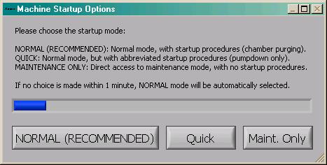
13 9. Remove the protective sheet from the top cover of the vacuum chamber. 10. Turn on the XDS 10 pump. Figure 2: BOC Edwards XDS10 Dry Scroll Pump (Image from Do not install a loaded xenon difluoride bottle at this time. Initial start-up tests are done with an empty bottle. Software Control Please note, some of this section of the manual describes features that are part of the X3 series system. One item in particular is that computer controlled temperature adjustment is not part of the X2 series and references to it should be ignored. The Xetch performs several activities when the system is turned on, including initializing hardware, purging the chambers, and preparing the software to run. There are three options displayed after the machine initializes the hardware, and this dialog box is shown below. Normal mode is the recommended method of startup for the Xetch. In this mode, the machine pumps and purges all of the machine chambers, assuring the user that the chambers are purged. In Quick mode, the chambers are simply pumped down, with no purging performed. This mode is useful when the state of the system is known upon startup, and no purging is necessary. In Maintenance only mode, the etch menu and load sample menu are disabled, and only the maintenance menu can be reached. This mode is useful when there is a machine fault that needs to be resolved by a technician. If no choice is made for one minute, Normal mode is selected by default. This allows the system to start up unattended. Page 13
14 Page 14

15 Xetch Log in The MEMS Equipment Company TM The Xetch is set up so that individual users are required to log in to the system. When starting the Xetch the prompt below will be displayed. Each operator is required to input their username and password which will be assigned to them by the system administrator. The KB button beside the Username and Password field can be used to access the on-screen keyboard. Page 15
.")
16 Main menu The MEMS Equipment Company TM The system administrator can log in to the system by inputting admin as the username. A password can be created after the initial log in as the administrator (for the first login, the password field should be left blank). Upon a successful login, the main menu will be displayed as shown below. The machine status is shown in the bottom left corner. When the main menu is displayed, the chamber is under vacuum and ready for use. A schematic for the machine is shown on the right. Red dots denote closed valves, while green dots represent open valves. Pressure gauges for the main chamber, and two expansion chambers are at the bottom right. The three options available on the main menu consist of performing an etch, loading/unloading a sample, and accessing the maintenance menu. Sample Loading To load/unload a sample: 1. Press unload/load sample on LCD screen. The system will go through prompts to ensure a correct decision: Are you sure? Press YES if you re sure, NO if you re not. This prompt is provided since the load/unload process can be time consuming and is inconvenient if accidentally started. The system begins chamber purges and flushing cycles to evacuate the chamber, shown below. Page 16


17 2. Swing the microscope out of the way of the chamber. 3. When the chamber is vented, the dialog box below will appear and you can open the chamber lid. The lid will rest open on the stop behind chamber. 4. If desired, load a sample. 5. Close the lid. Page 17
18 6. Press Done on LCD screen as shown below, the system will go through a purging cycle prior to chamber pump-down. As a side note, the Examine button only pumps the chamber down, without purges, so that the system can be quickly vented to load the sample. This is very useful when examining a sample away from the system to prevent moisture from accumulating in the chamber. However, it is always necessary to press Done before etching the sample. 7. During the pumping cycle, a click sound will be heard that indicates that the ventilation shroud can be moved. Viewing the Log The log may be viewed by clicking on the View Log button on the maintenance menu. The log file is a database that is queried by beginning date and ending date. The Today : button will automatically set the dates to the current month, day, and year. The lot number, username, recipe, note s keyword(s), and/or etching mode used can further specify your search. Wildcard characters (*,?) may be used to fully specify the search criteria. Page 18
19 If the boxes are left blank, clicking the search button will reveal all history info, displayed in a tabular form. Figure 1. Database Information screen. The export data button allows you to export all of the information shown in the table to a tab-separated text file that can be opened in the program of your choice, such as Microsoft Excel, Microsoft Access, and Microsoft Word, as shown below. Choosing a destination folder can be done by clicking on the folders icon at right side of the File Dialog screen. A default folder for saving log files and photos may be selected in the System Configuration Menu. File names are automatically entered in this form, ( _001.txt). This represents the year, month, day, and the number of the export for that day. Page 19
20 Besides being able to export the information, a selection from the displayed in the database information screen (see Figure 2), the information for a particular date and time can be accessed by highlighting the row of information desired and clicking the detailed info button. Note that the file is automatically scrolled to the bottom of the file, the Top or Bottom buttons are used to scroll instantly to the top or to the bottom of the log file. The result of the detailed information display is below. One unique feature of this menu is that comments can be typed into the Notes area (however, the number of characters is limited to 250). One other item to note is that the Average Overall Cycle time is not the average of the expansion chamber cycle times, but is computed by dividing the total run time divided by the number of cycles. Page 20
21 Other Main Menu items At the bottom left side of the main menu are buttons for changing the user s password and logging out. The log shows all of the operations that have been recently performed. The log can also be useful for accessing the exact start and end times of a run. The change password button allows a user to change their password by entering their username and previous password. The log-out button is used to exit the system. A prompt will appear once the button has been pressed inquiring if the user wishes to log out. Once the log out has been completed the system returns to the login screen. Page 21

22 Software operation details Recipe Storage To save a recipe, click on the save button located near the top of the perform etch screen. The save new recipe screen is pictured below. By using the toggle switch in the middle of the screen users can save the new recipe to their Personal Directory or the accessible to all users Global Recipes directory (the ability to save recipes to the global directory may be turned off for some users as described below). Recipe Manager The recipe manager may be used to copy other users recipes, located in their personal directory to the current user s personal directory. This option is limited to users with configurable etch access. The current user s personal recipes are displayed in the left box (in this case admin). The personal directory for other users is found in the right box. The pull down bar at the top right can be used to select from the personal recipes of various users. To copy a recipe into the current user s directory, select the desired recipe and click on the left arrow icon between the two directory windows. A recipe may also be copied from the user s personal directory to the global directory (if the user has global write access). This is done by highlighting a recipe in the user s directory, selecting Global Recipes in the right window and then using the right arrow to copy it to the Global Directory. Page 22

23 Performing an Etch In order to perform an etch, the perform etch button in the main menu must be selected. The Xetch will prompt you to enter the lot number of the sample being etched. Press done once number is entered. The perform etch screen is shown below with lot number, EXAMPLE in this case; the screen pictured is for the normal etch mode. It is important to note that in the perform etch screen, some options may not be available to certain users depending on the privileges which were given during the creation of their account. The Xetch software may be run in one of three operating modes that can be used during an etch. Only one operating mode (Normal) is included with the system. The others are optional upgrades. The etch mode at the bottom middle of the perform etch screen can be used to select the etch mode. The normal mode, (included at delivery) utilizes a pulsed etch with a set xenon difluoride pressure and etch time. An advanced normal etch mode (optional upgrade) allows for the user to set the expansion chamber pump-out pressure between cycles. The flow through mode (optional upgrade) creates a continuous flow of xenon difluoride. All three modes offer unique advantages; therefore the user must determine which etch mode will be best suited for his/her process. Each of these modes is described in detail in the following pages. Page 23

24 Etch Menu Features On the right side of the perform etch screen a valve schematic of the Xetch is shown so that the user can monitor the machine operation. In addition to this, at the bottom of the right side of the screen are two counters. The first counter displays how much time has transpired during the etch portion of the cycle. The second counter shows the number of cycles completed. At the very bottom of the screen; START ETCH, this is used to begin the etching process; STOP, this is used to end the etch prematurely; CHANGE CYCLES button which at any time during an etch can be used to add cycles to the etch in-progress. Once selected, the Change # of Cycles menu on next page, is prompted. The top row of arrows will add cycles in this order, (right to left); ones, tens, hundreds, and thousands; the lower row of arrows, having the same values, will remove cycles. All the user has to do is click on the designated arrow for the desired number of cycles needed to be added to the etch in-progress. For an example, an extra 125 cycles have been added to the etch by clicking the right most arrow (ones) five times, the next right most arrow (tens) twice, and the 2 nd from left most arrow (hundreds) once. NOTE: The CHANGE CYCLES button will only appear on the etch screen, if the etch parameter Soft Stop is set to TRUE, and only once etching has been started. Page 24
.")
25 If Soft Stop is made TRUE in the Etch Parameters menu, the Xetch will allow the current cycle to finish before ending the entire etch. If the STOP button is pressed twice, the Xetch will prompt the above menu (See also Soft Stop on page Error! Bookmark not defined.). Choosing Yes, Hard Stop will end the etch cycle immediately and return the user to the main menu. If No, Keep Waiting is chosen only the current cycle will be completed before returning the user to the main menu. At the bottom of the screen there is a figure labeled ETA. This feature displays the expected completion time. The ETA is continuously updated during the process run. Once the desired recipe settings have been chosen then etching can be initiated. By pressing the Start Etch button at the bottom left, the set values are stored and used to complete the desired etching sequence. At this point all of the controls will be disabled except for the stop button. Page 25
26 At the bottom left side of the main menu are buttons for viewing the Xetch Log, changing the user s password, and logging out. The log shows all of the operations that have been recently performed. The log can also be useful for accessing etch information, such as the exact start and end times of a run. The change password button allows a user to change their password by entering their username and previous password. The log out button is used to exit the system. A prompt will appear once the button has been pressed inquiring if the user wishes to log out. Once the log out has been completed the system returns to the login screen. Performing an Etch in the Normal Mode Normal Mode Etching Variables Number of cycles Since the Xetch is primarily a pulsed xenon difluoride etching system, the duration of etching is controlled by the number of cycles. A cycle consists of the xenon difluoride sublimating to the set pressure in the expansion chamber, etching for a set amount of time and evacuation of the main chamber and expansion chambers. Since the Xetch utilizes two expansion chambers the time waiting for the filling up of each expansion chamber is minimized. Etch Time When the valve between the main chamber and expansion chamber is opened the pressure equilibrates and the etching process begins. The etch time is the time between the opening of the valve between the expansion chamber and the process chamber and the opening of the valve between the process chamber and the pump. XeF 2 Pressure In order to introduce the proper amount of xenon difluoride into the main chamber a set pressure charge of xenon difluoride must be delivered to the expansion chamber. Because xenon difluoride has a vapor pressure of ~4T at room temperature the upper limit for the XeF 2 pressure is approximately 4T. Due to the slightly elevated temperature inside of the etcher cabinet, you may be able to get considerably higher XeF 2 pressures, however. N 2 Pressure Nitrogen can be added into a recipe to improve selectivity. The pressure obtained in the expansion chamber likewise controls the amount of nitrogen introduced into the process chamber. The above variables can be set either by moving the white slider on the scroll bar or by tapping or depressing on the arrows at the top and bottom of the scroll bar to increment each value or by direct entry through the keyboard. Additionally, a range button is included for the number of cycles, etch time and nitrogen pressure so that the user can input higher values than the default range allows. The perform etch screen is shown below in normal mode. Page 26

27 Performing an Etch in the Advanced Normal Mode The operation of the Xetch in the advanced normal mode (optional upgrade) is similar to the normal mode; however in the advanced mode, which is a XeF2 only process, the user can set the pump-down pressure in the expansion chamber. The advanced normal mode allows for full optimization around the etch rate and cycle time leading to a higher throughput. Advanced Normal Mode Etching Variables Number of cycles Since the Xetch is primarily a pulsed xenon difluoride etching system, the duration of the etch is controlled by the number of cycles. A cycle consists of the xenon difluoride sublimating to the set pressure in the expansion chamber, etching for a set amount of time and evacuation of the main chamber and expansion chamber. Since the Xetch utilizes two expansion chambers the time waiting for the filling up of each expansion chamber is minimized. Etch Time When the valve between the main chamber and expansion chamber is opened the pressure equilibrates and the etching process begins. The etch time is the time between the opening of the valve between the expansion chamber and the process chamber and the opening of the valve between the process chamber and the pump. Page 27

28 XeF 2 Pressure The MEMS Equipment Company TM In order to introduce the proper amount of xenon difluoride into the main chamber a set pressure change of xenon difluoride must be delivered to the expansion chamber. Because xenon difluoride has a vapor pressure of ~4T at room temperature the upper limit for the XeF 2 pressure is approximately 4T. Due to the slightly elevated temperature inside of the etcher cabinet, you may be able to get considerably higher XeF2 pressures. Pump-out Pressure The pump-out pressure allows the user to set the pressure to which the process and expansion chambers are pumped down to during the evacuation portion of the cycle. The above variables can be set either by moving the white slider on the scroll bar or by tapping or depressing on the arrows at the top and bottom of the scroll bar to increment each value exponentially. Additionally, a range button is included for the number of cycles, etch time and nitrogen pressure so that the user can input higher values than the default range allows. The perform etch screen is shown on the following page for advanced normal mode etching. Performing an Etch in the Flow Through Mode In the flow through mode, (optional upgrade), a continuous flow of xenon difluoride is maintained by keeping V1, V2 and V7 open. As a result the process chamber is always filled with xenon difluoride, which will yield shorter cycle times. The system is controlled by pulsing the roughing pump s vacuum valve according to the etch recipe. Page 28

29 Flow Through Mode Etching Variables Number of Cycles In the flow through cycle mode, the xenon difluoride pressure reaching the maximum pressure and the vacuum valve opening long enough to pump the system down to the minimum pressure defines a cycle. Maximum Pressure The maximum pressure is the highest pressure of xenon difluoride that is achieved in the process chamber prior to the vacuum valve opening. If the pressure were to reach in excess of 300 T, all valves are closed to prevent over-pressurization leak. Minimum Pressure The minimum pressure is the lowest pressure of xenon difluoride in the process chamber prior to the vacuum valve closing. The above variables can be set either by moving the white slider on the scroll bar or by tapping or depressing on the arrows at the top and bottom of the scroll bar to increment each value exponentially. Additionally, a range button is included for the number of cycles so that the user can input higher values than the default range allows. The Flow Through Cycle etch screen is shown below for flow through cycle mode etching. Page 29
30 Flow Through mode can also be operated in a Timed mode. Total Time In the timed flow through mode, where the total etch time is specified and the etch continues cycling until reaching the etch time. The Timed Flow Through etch screen is shown below. Page 30
31 Maintenance Menu WARNING MAINTENANCE MODE SHOULD ONLY BE USED BY THOSE INDIVIDUALS WHO UNDERSTAND THE RISKS OF EXPOSURE TO XEF2 AND ARE FULLY TRAINED IN THE USE OF THE MAINTENANCE ACTIVITIES FOR THE SYSTEM. The maintenance menu may be accessed via the maintenance menu button found on the main menu screen. For users without maintenance privileges the maintenance menu will not be accessible. Within the maintenance menu there are nine options. These options consist of adding and deleting users, editing the configuration menu, leak-back checking the system, purging the main chamber, gauge recalibrating, changing the xenon difluoride bottles (see page 54), exiting the Xetch software, viewing the full Xetch log, and returning to the main menu. Each of these operations will be discussed in the following sections. In addition to the nine options available in the maintenance menu, the approximate amount of xenon difluoride consumed from each bottle is displayed in the middle left section of the screen. Page 31
32 Viewing the Full Log The full log may be viewed by clicking on the View Full Log button within the maintenance menu. The log file is a database that is queried by beginning date and ending date. The Today : button will automatically set the dates to the current month, day, and year. The lot number, username, recipe, note s keyword(s), and/or etching mode used can further specify your search. Wildcard characters (*,?) may be used to fully specify the search criteria. Page 32
33 If the boxes are left blank, clicking the search button will reveal all history info, displayed in a tabular form. Page 33

34 Figure 2. Database Information screen. The export data button allows you to export all of the information shown in the table to a tab-separated text file that can be opened in the program of your choice, such as Microsoft Excel, Microsoft Access, and Microsoft Word, as shown below. Choosing a destination folder can be done by clicking on the folders icon at right side of the File Dialog screen. A default folder for saving log files and photos may be selected in the System Configuration Menu. File names are automatically entered in this form, ( _001.txt). This represents the year, month, day, and the number of the export for that day. Page 34

35 Besides being able to export the information, a selection from the displayed in the database information screen (see Figure 2), the information for a particular date and time can be accessed by highlighting the row of information desired and clicking the detailed info button. Note that the file is automatically scrolled to the bottom of the file, the Top or Bottom buttons are used to scroll instantly to the top or to the bottom of the log file. The result of the detailed information display is below. One unique feature of this menu is that comments can be typed into the Notes area (however, the number of characters is limited to 250). One other item to note is that the Average Overall Cycle time is not the average of the expansion chamber cycle times, but is computed by dividing the total run time divided by the number of cycles. Page 35

36 For system errors and maintenance related issues, the full log can offer valuable information. To display the details of the full log, click details on the display detailed etch info screen, shown on next page, to view the log file in its entirety. In the notepad program, the date, time, and actions executed are displayed as shown below. The level of detail included in the details of the full log is controlled by the settings related to the log file in the System Configuration Menu, which is described later. Page 36

37 User Manager The user manager can be used to add, delete and assign privileges to various users. Only the System Administrator can access the user manager. Users can be added using the New button, while current users can be removed using the Delete button. To change a user s privileges the Edit button can be used. To exit the User Manager and return to the maintenance menu click on Done. Page 37
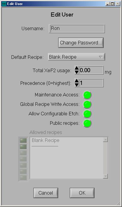
38 Adding a User The MEMS Equipment Company TM A new user can be added to the system by clicking on the new button within the user manager. The edit user screen will appear as shown on next page. The name of the user should be entered into the User Name box and a password then entered, if desired. If no password is entered, a reminder message stating that the user has no password will be displayed and if this is OK. The users default recipe can then be selected and the amount of XeF2 can be entered for the user s starting point, if necessary, or is typically left at 0. Later, this value can be examined to show the total quantity of XeF2 used by the user. Three options (privileges) are available for users. A user can be given permission to access the maintenance menu thus giving them the ability to execute such functions as changing the machine configuration, changing the xenon difluoride bottle, and viewing the full log. WARNING MAINTENANCE MODE SHOULD ONLY BE PROVIDED TO THOSE INDIVIDUALS WHO UNDERSTAND THE RISKS OF EXPOSURE TO XEF2 AND ARE FULLY TRAINED IN THE USE OF THE MAINTENANCE ACTIVITIES FOR THE SYSTEM. Global Recipe Write Access allows a user to save an etch recipe in the global recipe location so that all other users can select the corresponding etching conditions. This also means that the user could potentially alter the recipes in the global recipe area. Allow Configurable Etch gives the user the ability to create their own recipe and save it in their file. If none of these options are selected the user may only use the default recipe assigned to them. Public recipes allows the recipes of the user to be visible to other users. For users with no privileges a default recipe is required. It is recommended that foundry operator accounts be set up with no privileges. A number of allowed recipes can be given to the user and by checking the box next to the recipe name, it can be enabled. For example, a user without the ability to configure their etch can have, say 20 recipes. However, if only 1 is turned on, they will have access to only that 1 recipe. This is useful for those operators that may have a series of lots to process and the Administrator can enable the appropriate recipe for that operator as needed. Page 38
39 Page 39

40 Configuration Menu The MEMS Equipment Company TM The configuration menu can be edited to change various system operations relating to basic system parameters, startup parameters, standby parameters, maintenance parameters, etch parameters, and validation codes; NOTE: The validation code should only be changed by the system administrator. To edit the configuration menu select the Edit CFG option in the maintenance menu. The following options will appear as follows: Page 40

41 System Configuration Menu The MEMS Equipment Company TM The system configuration options screen is displayed below. Each of the options is briefly explained: Card Present Query for the presence of system controller card. This should normally be true for systems. Otherwise, the software will operate in a simulation mode. Machine Present Query for the presence of Xetch machine. This should also be normally set to true. Keyboard Present Query for the presence of an external keyboard. It is suggested to leave this as false, even if there is a keyboard since setting it to true removes many of the on screen keyboard functions that may be convenient. Page 41
42 Log Data Keeps track of machine operation for incorporation into the log. Log Low Level Keeps track of all operating machine details in the full log. Full Shutdown The MEMS Equipment Company TM Allows for the entire system to be shutdown when the Xetch software is shutdown. XeF2 Bottle #1 Filled Query for the presence of XeF2 lecture bottle #1 (does not have to be full). XeF2 Bottle #2 Filled Query for the presence of XeF2 lecture bottle #2 (does not have to be full). Alternate Bottles Alternate between XeF2 bottles, or use both at the same time. Two Process Gauges Specifies whether there are two process pressure gauges installed on the system. This feature is designed to provide a temporary backup if the lower process pressure gauge fails such that the option can be set to false, hence enabling the system to run on just the higher pressure (atmospheric) pressure gauge. Although the high pressure gauge is not very accurate at lower pressures, it will at least allow the system to run. Show warnings Allows the system to display on-screen warnings. Such warnings include vacuum and temperature related warnings. Automatic Gauge Recalibration This feature allows the user to decide if and how often a gauge calibration will be executed automatically. Show Last Calibration Time Enables system to display how long it has been since last gauge recalibration. Default File Save Path Allows the user to define a default folder that log files and images will be saved to. Maximum Log Size Maximum space allocated to the log for storage of log data. As the log exceeds this max size, the oldest data is purged. Although it may be tempting to have large log files, they may prove to be difficult to open in most text viewers. Process Volume Volume of process chamber. This should be 330 cm^3 for 4 inch systems and 660 cm^3 for 6 inch systems. Exp. #1 Volume Volume of expansion chamber #1. This should be typically set to 560 cm^3. Page 42
43 Exp. #2 Volume Volume of expansion chamber #2. This should be typically set to 560 cm^3. Process Gauge Crossover The MEMS Equipment Company TM This is the crossover pressure at which to switch between the lower and higher pressure process pressure gauges. Remote Connection Timeout If the main system loses network connectivity with a remotely connected machine (optional upgrade) for this amount of time, that machine is automatically disconnected. If this number is set to zero, there is no timeout. Image Brightness Red brightness, green brightness, and blue brightness settings (used only for the optional upgrade for the image acquisition system). Automatic Gauge Calibration Time Sets the number of days between each automatic gauge calibration. XeF2 Warning Level If either XeF2 bottle s estimated remaining XeF2 falls below this set point, a warning is displayed on the Main and Etch menus, in addition, in the Maintenance menu, XeF2 usage is highlighted yellow if it is below the setpoint. Startup Configuration Menu The startup parameters options screen is displayed on next page. Each of the options is briefly explained. Process Purge Cycles Allows the user to set the number of purge cycles for the process chamber during the machine startup. Process Purge High Allows the user to set the nitrogen pressure for the process chamber purge cycles during the machine startup. Process Purge Low Allows the user to set the vacuum pressure for the process chamber purge cycles during the machine startup. Exp. #1 Purge Cycles Allows the user to set the number of purge cycles for expansion chamber #1 during the machine startup. Exp. #1 Purge High Allows the user to set the nitrogen pressure for expansion chamber #1 purge cycles during the machine startup. Exp. #1 Purge Low Allows the user to set the vacuum pressure expansion chamber #1 purge cycles during the machine startup. Page 43
44 Exp. #2 Purge Cycles The MEMS Equipment Company TM Allows the user to set the number of purge cycles for expansion chamber #2 during the machine startup. Exp. #2 Purge High Allows the user to set the nitrogen pressure for expansion chamber #2 purge cycles during the machine startup. Exp. #2 Purge Low Allows the user to set the vacuum pressure expansion chamber #2 purge cycles during the machine startup. Flush Cycles Allows the user to set the number of flush cycles during the machine startup. Flush Time #1 Allows the user to set the amount of time that V7, V5, V8, V3, V11, V15, and V14 are open during the flush cycle. Flush Time #2 Allows the user to set the amount of time that V7, V5, V8, V3, V11, V15, V14, V6, and V9 are open during the flush cycle. Flush Time #3 Allows the user to set the amount of time that V3, V11, V15, V14, V6 and V9 are open during the flush cycle. Flush Time #4 Allows the user to set the amount of time that V3, V11, and V10 are open during the flush cycle. Page 44

45 Standby Configuration Menu The standby parameters options screen is displayed on next page. Each of the options is briefly explained. Process Purge High Allows for the user to set the nitrogen pressure in the process chamber for purging the system during the load/unload cycle. Process Purge Low Allows for the user to set the pressure that the process chamber is pumped down to when purging the system during the load/unload cycle. Process Standby Allows the user to set the process chamber base pressure for the pump-down process. Exp. #1 Purge High Allows for the user to set the nitrogen pressure in expansion chamber #1 for purging the system during the load/unload cycle. Exp. #1 Purge Low Allows for the user to set the pressure that expansion chamber #1 is pumped down to when purging the system during the load/unload cycle. Page 45
46 Exp. #1 Standby The MEMS Equipment Company TM Allows the user to set the base pressure in expansion chamber #1 for the pump-down process. Exp. #2 Purge High Allows for the user to set the nitrogen pressure in expansion chamber #2 for purging the system during the load/unload cycle. Exp. #2 Purge Low Allows for the user to set the pressure that expansion chamber #2 is pumped down to when purging the system during the load/unload cycle. Exp. #2 Standby Allows the user to set the base pressure in expansion chamber #1 for the pump-down process. ATM Pressure Allows the user to define the set point for the atmospheric pressure light to come on during the venting process. V13 Low Pressure Point Allows user to define the pressure at which Valve 13 opens. Load Purge Cycles Allows user to set the number of purge cycles for during the load cycle. Unload Purge Cycles Allows user to set the number of purge cycles for during the unload cycle. Load Sample Timeout Allows the user to set the amount of time for which the nitrogen vent gas continues to when the chamber is at atmospheric pressure. Pump-down Differential When the system chambers are being evacuated, a check is made to see if one of the expansion chambers is higher than the other by this amount. If so, the chamber at the higher pressure is evacuated first, until both chambers reach the same pressure; then both chambers are evacuated together. This is to avoid back streaming of gas from one chamber to the other through the vacuum system. Page 46

47 Gas Bottle Change Parameters Menu The maintenance parameters options screen is displayed on next page. Each of the options is briefly explained Pre-Change Cycles Allows user to set the number of purge cycles prior to disconnecting the XeF2 lecture bottles. Pre-Change High Allows the user to set the nitrogen pressure for the purge cycles prior to disconnecting the XeF2 bottles. Pre-Change Vac Time Allows the user to set the amount of time that the vacuum valve is open prior to disconnecting the XeF2 bottles. Closed Bottle Cycles Allows user to set the number of purge cycles to remove atmospheric gas from the lines following a XeF2 bottle change. Closed Bottle High Allows user to set the nitrogen pressure for the purge cycles following a XeF2 bottle change. Page 47

48 Closed Bottle Vac Time Allows user to set vacuum time for the purge cycles following a XeF2 bottle change. Post-Change Cycles Allows user to set the number of cycles used to ensure that the XeF2 bottle is operating correctly. Post-Change High Allows user to set the XeF2 pressure for the conditioning cycles following a XeF2 bottle change. Post Change Vac Time Allows user to set the vacuum time for the conditioning cycles following a XeF2 bottle change. Etch Configuration Menu The etch parameters options screen is displayed on the next page. Each of the options is briefly explained: Soft Etch Stop Allows the user to stop etching; yet allow the current cycle to finish before exiting. As opposed to a hard etch stop; which can still be performed by touching the STOP button twice, which immediately evacuates all chambers closes all valves, and returns to the main menu. Allow In-Progress Cycle Changes Allows the user to add additional cycles to an etch while etch is still in progress. Page 48
49 Show overtime warning The MEMS Equipment Company TM If this is enabled, a warning message will be displayed to alert the user that the system is taking a longer time than is expected to complete an etch cycle. The overtime associated with this feature is set via the Overtime threshold. Typically, a long time such as 100 seconds is recommended to avoid an accidental warning. V3/V11 Keep-open feature This feature is typically used in conjunction with etches that use nitrogen. Enabling this feature in combination with setting the V3/V11 Keep-open N2 pressure allows the two expansion chamber side nitrogen valves to remain open throughout the etch and can reduce cycle times. However, if V3/V11 are kept open at low nitrogen fill pressures (approximately 5 torr or below), accurate expansion chamber fills may become difficult. Therefore, this feature has a threshold value below which it will not be enabled. This threshold value is set via the V3/V11 Keep-open N2 pressure setting. Delay.MPG gen. until done This feature is only related to the systems that have the optional image acquisition system option. Enabling it allows the video file to be created after the etch finishes to minimize the load on the computer processor during the etch. Intermediate Pump-down Pressure Allows the user to set the intermediate pressure used for expansion chamber through main chamber pump-downs during an etch cycle. Pressure Estimation Delay Allows the user to set the delay after filling of a chamber before the pressure is measured. This is done to keep track of the pressure fill overshoot the extra pressure achieved after a fill valve is closed. Pressure Estimation Tau The pressure overshoot is filtered using an exponentially weighted moving average filter. This parameter allows the user to set the time constant for that filter. XeF2 Pressure Estimation # Bins The pressure overshoot is also recorded separately for different fill targets. This parameter allows the user to set the number of bins that the pressure range between 0T and 8T is divided into. N2 Pressure Estimation # Bins Allows the user to set the number of pressure overshoot bins for N2 pressure between 0T and 30T Max Pressure Estimation Age Allows the user to predetermine the longest amount of time, between 0 and 120 hours, that the machine will be pumped -on without any processing. Pressure Estimation Pre-Cycles Allows the user to set the number, between 0 and 10, of pre-cycle pressure purging cycles. Etch Buffer Time During an etch cycle, one expansion chamber can be evacuated while the other expansion chamber is being used for etching. However, it is essential that while the expansion chamber is being evacuated that the main chamber not also be evacuated since it is possible that this could interfere with the etch cycle. To avoid this potential overlap of evacuating an expansion chamber and then simultaneously needing to pump out the main chamber, an Etch Buffer Time is specified. Setting this parameter to 5 Page 49

50 seconds requires that there be at least 5 seconds between completion of the evacuation of an expansion chamber and the need to evacuate the main chamber. This time is determined during the first seven cycles of the etch, afterwards, if the expansion chamber is fully evacuated the Etch Buffer Time before the need to evacuate the main chamber, the evacuation of the expansion chamber will occur during the etch cycle. N2 fill pressure delta This setting relates to the pressure that the nitrogen inlet valves, V14/V15, close in advance of reaching the expansion chamber nitrogen fill pressure setpoint to minimize the pressure jump during expansion chamber evacuation. Page 50

51 Leak-Back Utility The MEMS Equipment Company TM To test the leak-back rate of each of the chambers, the Leak-back Utility can be used. This program pumps down all chambers, and then closes all valves for a pre-set amount of time. It then estimates the leak-back rates for each chamber and displays them. To use this utility, first choose the duration of the test, the duration of the pumpdown before test, and then press Start Test. The test will be performed, and the rates will be displayed. When the test is complete and you have observed the rates, press Done to return to the Maintenance Menu. Page 51

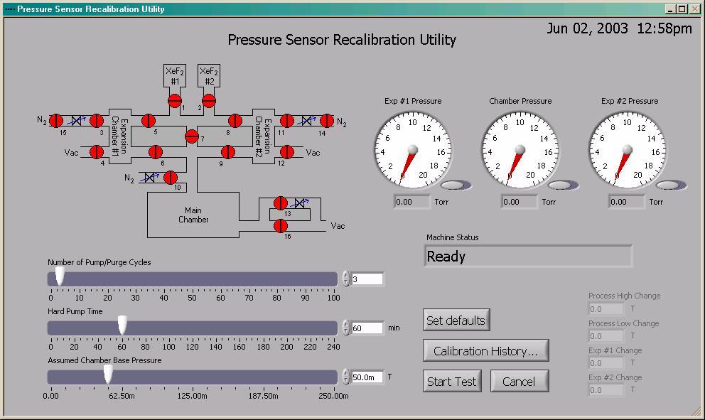
52 Main Chamber Purge To repeatedly pump and purge the main chamber to remove residual gas or water vapor, the Chamber Purge Utility can be used. First, set the parameters for the purge routine, including N2 fill high-pressure, high-pressure time, pump-down low pressure, low-pressure time, and number of purge cycles. Then press, Start to start the cycle. At any time, the Cancel button can be used to end the routine and return to the Maintenance Menu. Pressure Sensor Recalibration Utility Capacitance manometers may drift over time indicating less accurate readings. The gauge recalibration utility is a method to periodically recalibrate them. To recalibrate the capacitance Manometers, set the number of purge cycles, length of pump time, and assumed chamber base pressure. The manometers are zero calibrated to.05 T or 50 mt, which is the assumed base pressure of the system. Pressing the Calibration History button accesses a log file for the recalibration function. The Set Defaults button can be used to save recalibration settings for easy one-touch use. Set the preferred settings and press Set Defaults, this will allow these parameters to be saved and appear each time calibration is performed unless otherwise set. When desired parameters are set press Start Test button and calibration will begin. Occasionally executing the calibration a second time may be needed to achieve calibration. An automatic calibration function may be set to True in the configuration menu under System Configuration. This function will automatically recalibrate the capacitance manometers at a low-usage time, typically at night. The last calibration time is then displayed on the main menu. Page 52
53 Page 53
54 XeF 2 Bottle Change Bottle Change General information XeF 2 Counter Reset Before proceeding with a bottle change, be aware that the XeF 2 usage display will be reset to zero once the bottle is changed. You may wish to record the usage displayed before changing for your records. The usage information can be found by clicking the Maintenance Menu. The information is located at the top left under Approx. XeF 2 Usage. Parts List Swagelok Gaskets ( NI-4-VCR-2-VS or NI-4-VCR-2-GR-VS 5/8 and 3/4 Standard Wrenches Latex Gloves Time allocation The time to complete the bottle change is typically between 30 to 45 minutes. Changing XeF 2 Bottles WARNING IT IS IMPERATIVE THAT THESE DIRECTIONS BE FOLLOWED EXACTLY TO SAFELY CHANGE THE XENON DIFLUORIDE BOTTLE(S). Beginning from the Main Menu screen, click on Maintenance Menu. Page 54
55 To change the gas bottles click on the top right button, Change XeF 2 bottle, shown in Figure 4. Page 55
56 You will then be prompted to choose which bottle you would like to change, #1 or #2 (the locations of the bottle connections is shown in Figure 3). Page 56

57 XeF 2 Bottle # 1 XeF 2 Bottle # 2 Figure 3. Bottle Connection Locations. Page 57

58 Figure 4. Maintenence menu. The Xetch will automatically test the pressure of the bottle you ve chosen to change, #1 for example. This provides a test method to qualify XeF 2 pressure at any point in time as shown on next page. Please note that the 2 Torr value used below is an illustration and your organization may decide to choose another pressure value to make the bottle change determination. For example, if the pressure displayed is above approximately 2 Torr, click NO and you will be returned to the maintenance menu. If the pressure is below approximately 2 Torr, click YES, and the bottle change will continue. Page 58

59 If you have chosen to change the XeF 2 bottle, you will be instructed to close the manual valve on the bottle. Once you have closed the proper bottle s valve, click OK as shown below. NOTE: Clicking Stop Button At Lower Right Can Stop Process At Any Time The Xetch will proceed to clear out or purge the lines to assure all XeF 2 gas is removed from the system lines. This will take approximately 2 minutes. You will then be instructed as below to remove the gas bottle, refill it, and replace with full bottle. Be sure to leave the manual valve closed. Page 59
60 Removing Gas Bottle To remove the XeF 2 bottle you have chosen, use a 3/4 standard wrench on the female or larger nut. You will also use a 5/8 standard wrench on the male or smaller nut that is attached to the bottle. The male nut is held firmly, while rotating the wrench on the female nut to loosen the female nut. Replacing Gas Bottle WARNING THERE MAY STILL BE RESIDUAL XENON DIFLUORIDE IN THE REMOVED BOTTLE SO BE CERTAIN THAT THE BOTTLE VALVE REMAINS CLOSED. Before reattaching the gas bottle after verifying the old gasket is removed, a nickel-plated Swagelok gasket (NI-4-VCR-2-VS) must be inserted between the male and female nuts to insure a good seal (see A. in Figure 5). A retainer gasket (NI-4-VCR-2-GR-VS) is also available and acceptable to use on the Xetch, the retainer gasket makes completing the seal less complicated by attaching itself over the VCR fitting gland. The un-retained gaskets require balancing the fittings until finger tight is established but can certainly be used successfully. Use latex gloves when handling the gaskets to prevent dust or grease degrading the seal s performance. If the gasket falls on the floor or is suspected of having scratches, THROW IT AWAY. If not, you could damage the VCR gland or face. Mate the male and female nuts to finger tight by turning female nut clockwise (see B. in Figure 5). Mark the male and female nuts position with a line across each to establish 1/8 turn (see C. in Figure 5). Then holding the lower male nut firmly with the 5/8 wrench, turn the upper female nut with the 3/4 wrench clockwise 1/8 turn (see D. in Figure 5). Note that over tightening may damage the VCR gland and under tightening may result in poor gasket seal. CAUTION The steps on the next page must be followed exactly to ensure proper gasket installation. Page 60

61 (A.) (B.) (C.) Figure 5. VCR Gasket Assembly Procedure (Image from (D.) Page 61

62 The Xetch will ask you to double check that the manual valve is closed on the bottle. When positive that valve is closed click YES. If you decide not to change bottle and continue, click NO. If NO was selected you will be to the previous screen and must click YES once bottle is removed, refilled, and replaced. Once again, the Xetch will purge the lines to ensure a clean system before any XeF 2 is present, and leak test fittings to ensure a proper seal. If the seal leaks, a failure prompt will appear. Recommended steps would be to restart the leak-test up to three times by clicking yes, then check that the female nut is sufficiently tight. If leak still exists, replace the gasket. If leak-test is passed Click YES, and you will be prompted as shown to open manual valve on bottle. Turn manual valve counter clockwise to open. Click OK when task is complete. Completing Bottle Change If the Xetch accepts all parameters the bottle will then have been changed successfully. Click OK as illustrated on the prompt screen below. If bottle #2 also needs to be changed repeat these steps from beginning to end. Page 62
63 Maintenance Roughing Pump The MEMS Equipment Company TM The Xetch ships with an Edwards XDS10 dry scroll pump. This pump is does not use oil and therefore the maintenance is considerably less than a rotary vane pump. The primary maintenance is the replacement of the tip seal, which Edwards typically recommends performing this less than 30 minute operation on an annual basis. Please see the XDS10 manual for more details. Vacuum Interlocks The Xetch has two vacuum interlocks, one to make certain that the chamber is below approximately 400 Torr of pressure before permitting the source bottle valves (Valves 1 and 2) on the gas panel to open. The other interlock prevents all valves on the gas panel from opening if the pressure at the main vacuum line is above approximately 400 Torr. Xenon difluoride Physical Properties Density 4.32 g/cm 3 MW MP C FP None Vapor Pressure 3.9 Torr (at room temperature) Xenon difluoride is very volatile and should be stored cold to keep it from decomposing. Safety XeF 2 does not explode on contact with moisture or air, nor does it form compounds that explode. The "exploding XeF 2 " story comes from impurities in the XeF 2, according to Neil Bartlett, discoverer of noble gas chemistry in 1963 (and now professor of chemistry at the University of California at Berkeley). Specifically, XeF 4 is a common impurity. In the presence of moisture XeF 4 turns into XeO 3, which is a contact explosive. Lots of the early noble gas chemists had XeO 3 explosions due to working with XeF 2 that had XeF 4 in it. The XeF 2 that you buy has only trace XeF 4 impurities, so the total mass of explosive that could be generated under any circumstances is probably measured in tens milligrams - enough to cause a pop perhaps, but not dangerous. For further information refer to the Material Safety Data Sheet (MSDS) from Pelchem, one of the many suppliers of xenon difluoride. This MSDS can be found on the XACTIX website at Selectivity during etching XeF 2 shows very high selectivity of silicon versus SiO 2, silicon nitride, Al, Cr, photo-resist, and TiN. The Xetch's selectivity to silicon nitride is better than 100:1, and the selectivity to silicon dioxide is considerably higher. More data will be made available on the XACTIX website as performance specifications are compiled. Page 63
64 Xenon difluoride market pricing The MEMS Equipment Company TM Xenon difluoride is available from a number of worldwide suppliers. XACTIX maintains a list of suppliers, pricing and product specifications on its website. Please visit for more information. Xetch Specifications Wafer capacity The Xetch is designed to be manually loaded for superior substrate geometry flexibility. The Xetch is the ideal solution for those seeking cost effective R&D xenon Difluoride etch system. Built for high etch uniformity, simplicity, low cost of ownership, and a small footprint, the Xetch is well suited for both industrial users and universities. Wafer size limitations The unit comes in three versions, a system which is optimized for 4" wafers or smaller parts, a system which is optimized for 6" wafers or smaller parts, and a system which is optimized for 8" wafers or smaller parts. Gas and Vacuum System Valves The gas and vacuum system includes the following valves: V1: Xenon difluoride source #1 bottle V9: Process #2 isolation V2: Xenon difluoride source #2 bottle V10: Process chamber nitrogen source V3: Nitrogen #1 isolation V11: Nitrogen #2 isolation V4: Expansion chamber #1 vacuum V12: Expansion chamber #2 vacuum V5: Xenon difluoride expansion #1 isolation V13: Variable rough vacuum V6: Process #1 isolation V14: Expansion #2 nitrogen source V7: Xenon difluoride flow through mode isolation V15: Expansion #1 nitrogen source V8: Xenon difluoride expansion #2 isolation V16: Fast rough vacuum Page 64


.")

65 1. The MEMS Equipment Company TM Silicon etch rates The etch rate is very dependant on the feature size and amount of silicon to be etched. Etch rates as high as 15 um per minute on small parts are achievable, with lower rates on large wafers. (The Xetch is a pulsed etching system, so high rates should be achievable once the process is optimized). Data obtained from customers shows: Uniformity and repeatability on 6" wafers better than +-3% On a 6" Si wafer with 90% exposed area, etching 2 microns of Si in 14 minutes On a 4" Si wafer with 10% exposed area, etching 1 micron per minute. Page 65
Xactix XeF2 OPERATION MANUAL
 General Information The Xactix e-1 is a xenon difluoride (XeF 2) isotropic silicon etcher. XeF 2 is a vapor phase etch, which exhibits very high selectivity of silicon to photo-resist, silicon dioxide,
Arizona State University NanoFab XACTIX ETCHER. Rev A
 Arizona State University NanoFab XACTIX ETCHER Rev A Table of Contents Contents Table of Contents... 1 1. Purpose / Scope... 2 2. Reference Documents... 2 3. Equipment / Supplies / Material... 2 4. Safety...
Xactix Xenon Difluoride Etcher
 Xactix Xenon Difluoride Etcher 1 Introduction This tool is a Xactix e1 series XeF2 (Xenon Difluoride) based vapor phase etch system for isotropic and selective silicon etching. The XeF2 reaction with silicon
Title: Xactix XeF2 Etcher Semiconductor & Microsystems Fabrication Laboratory Revision: A Rev Date: 03/23/2016
 Approved by: Process Engineer / / / / Equipment Engineer 1 SCOPE The purpose of this document is to detail the use of the Xactix XeF2 Etcher. All users are expected to have read and understood this document.
JETFIRST 150 RTA SYSTEM OPERATING MANUAL Version: 2 Feb 2012
 JETFIRST 150 RTA SYSTEM OPERATING MANUAL Version: 2 Feb 2012 UNIVERSITY OF TEXAS AT ARLINGTON Nanofabrication Research and Teaching Facility TABLE OF CONTENTS 1. Introduction....2 1.1 Scope of Work.....2
Usage Policies Notebook for Xenon Difluoride (XeF 2 ) Isotropic Si Etch
 Isotropic Si Etch") Usage Policies Notebook for Xenon Difluoride (XeF 2 ) Isotropic Si Etch Revision date September 2014 2 Emergency Plan for XeF 2 Si Etcher Standard Operating Procedures for Emergencies Contact information
Usage Policies Notebook for Xenon Difluoride (XeF 2 ) Isotropic Si Etch Revision date September 2014 2 Emergency Plan for XeF 2 Si Etcher Standard Operating Procedures for Emergencies Contact information
University of MN, Minnesota Nano Center Standard Operating Procedure
 Equipment name: STS Etcher Badger name: STS Revision number: 3 Model: 320 Revisionist: Paul Kimani Location: Bay 3 Date: 1 October 2013 A. Description The 320 is a manually loaded batch plasma etching
UNITY 2 TM. Air Server Series 2 Operators Manual. Version 1.0. February 2008
 UNITY 2 TM Air Server Series 2 Operators Manual Version 1.0 February 2008 1. Introduction to the Air Server Accessory for UNITY 2...2 1.1. Summary of Operation...2 2. Developing a UNITY 2-Air Server method
Pegas 4000 MF Gas Mixer InstructionManual Columbus Instruments
 Pegas 4000 MF Gas Mixer InstructionManual Contents I Table of Contents Foreword Part I Introduction 1 2 1 System overview... 2 2 Specifications... 3 Part II Installation 4 1 Rear panel connections...
Plasma-Therm PECVD. Operating Characteristics. Operating Instructions. Typical Processes. I. Loading. II. Operating
 Plasma-Therm PECVD A PECVD (plasma enhanced chemical vapor deposition) reacts gases in a RF (radio frequency) induced plasma to deposit materials such as silicon dioxide and silicon nitride. This PECVD
Savannah S100 ALD at SCIF, UC Merced Standard operating Procedure
 This document covers the procedure that should be followed for normal operation of the Cambridge NanoTech: Savannah S100 (Atomic Layer Deposition ALD). This tool is design to be used with whole 4inch wafers.
Glove Box Installation Manual
 Glove Box Installation Manual 1998 by M. Braun Company File: GB-UNI-INS.DOC! Edition 08-00 by M. Boutin! Subject to be changed without notice Glovebox Installation Your Glove box has been fully assembled,
HumiSys HF High Flow RH Generator
 HumiSys HF High Flow RH Generator Designed, built, and supported by InstruQuest Inc. Versatile Relative Humidity Generation and Multi-Sensor System The HumiSys HF is a high flow version of the previously
SSI Solaris 150 RTA Revision /27/2016 Page 1 of 9. SSI Solaris 150 RTA
 Page 1 of 9 SSI Solaris 150 RTA The Solaris 150 RTA is a rapid thermal annealing system capable of handling sample sizes up to 100mm (4 diameter) or smaller. The system can anneal in N 2 and Forming gas
Standard Operating Manual
 Standard Operating Manual ARC12M Sputter Copyright 11.2015 by Hong Kong University of Science & Technology. All rights reserved. Page 1 Contents 1. Picture and Location 2. Process Capabilities 2.1 Cleanliness
AX5000 Operational Manual
 MIYACHI AMERICA CORPORATION The World Leader in Hermetic Sealing Systems AX5000 Operational Manual 0 Document #107-00092-001 Dec, 2013 AX5000 Operational Manual Miyachi America Corporation 1820 S. Myrtle
GA-300 Gas Analyzer. Technical Note. Overview. Front Panel. iworx Systems, Inc. GA-300
 Technical Note GA-300 Overview The GA-300 CO2 and O2 Gas Analyzer is easy to use, robust, and adaptable to human, animal, and plant applications. The GA-300 has two analog outputs to allow recording and
The HumiSys. RH Generator. Operation. Applications. Designed, built, and supported by InstruQuest Inc.
 The HumiSys RH Generator Designed, built, and supported by InstruQuest Inc. Versatile Relative Humidity Generation and Multi-Sensor System The new HumiSys with single or dual RH probes capabilities is
In Response to a Planned Power Outage: PPMS EverCool II Shut Down and Re-start Procedure
 PPMS Service Note 1099-412 In Response to a Planned Power Outage: PPMS EverCool II Shut Down and Re-start Procedure Introduction: Loss of electricity to the PPMS EverCool II should not cause damage to
Model 130M Pneumatic Controller
 Instruction MI 017-450 May 1978 Model 130M Pneumatic Controller Installation and Operation Manual Control Unit Controller Model 130M Controller is a pneumatic, shelf-mounted instrument with a separate
STS PECVD Instructions
 STS PECVD Instructions I. Introduction A PECVD (Plasma Enhanced Chemical Vapor Deposition) reacts gases in a RF- (Radio Frequency) - induced plasma to deposit materials such as SiO 2 and Si X N Y. This
FX134, FX1234, FX3030 Problem and Solutions
 FX134, FX1234, FX3030 Problem and Solutions Unit Will Not Power Up Turn the power switch on. The unit LCD will display revision program and filter life within 3 to 5 seconds after turning on unit. If this
ACV-10 Automatic Control Valve
 ACV-10 Automatic Control Valve Installation, Operation & Maintenance General: The Archer Instruments ACV-10 is a precision automatic feed rate control valve for use in vacuum systems feeding Chlorine,
BASIC Z-STACK AND TIME SERIES SCAN ON THE ZEISS LIGHTSHEET Z. 1
 BASIC Z-STACK AND TIME SERIES SCAN ON THE ZEISS LIGHTSHEET Z. 1 The front door of the main body of the instrument may be open when you arrive. Take the sample chamber and slide it into position with the
SomnoSuite FAQ. Setup. Calibration 4. What are the calibration requirements for the SomnoSuite? Settings
 SomnoSuite FAQ V1.3 January 2015 Setup 1. How do I connect the SomnoSuite to my oxygen source? 2. Is there a way to speed up the downward movement of the pusher block when setting the empty position? 3.
Series Environmental Chambers
 3119-600 Series Environmental Chambers Challenges in Non-Ambient Testing Testing at non-ambient temperatures adds another layer of challenges to your testing laboratory. Ensuring you get accurate and stable
1)! DO NOT PROCEED BEYOND THIS MARK
! DO NOT PROCEED BEYOND THIS MARK") Operating Instructions for X-ray Photoelectron Spectrometer: Physical Electronics Model 555 XPS/AES (John H. Thomas, III, Ph.D., Electron Spectroscopy) Sample Insertion: figure 1. Sample insertion rod
Operating Instructions for X-ray Photoelectron Spectrometer: Physical Electronics Model 555 XPS/AES (John H. Thomas, III, Ph.D., Electron Spectroscopy) Sample Insertion: figure 1. Sample insertion rod
Arizona State University Center for Solid State Electronic Research. Table of Contents. Issue: C Title: Oxford Plasmalab 80plus (Floey) Page 1 of 8
 Page 1 of 8") Title: Oxford Plasmalab 80plus (Floey) Page 1 of 8 Table of Contents 1.0 Purpose/Scope... 2 2.0 Reference Documents... 2 3.0 Equipment/Supplies/Material... 2 4.0 Safety... 2 5.0 Set Up Procedures... 2
Title: Oxford Plasmalab 80plus (Floey) Page 1 of 8 Table of Contents 1.0 Purpose/Scope... 2 2.0 Reference Documents... 2 3.0 Equipment/Supplies/Material... 2 4.0 Safety... 2 5.0 Set Up Procedures... 2
R I T. Title: STS ASE Semiconductor & Microsystems Fabrication Laboratory Revision: Original Rev Date: 01/21/ SCOPE 2 REFERENCE DOCUMENTS
 Approved by: Process Engineer / / / / Equipment Engineer 1 SCOPE The purpose of this document is to detail the use of the STS ASE. All users are expected to have read and understood this document. It is
Nanofabrication Facility: PECVD SOP Rev. 00, April 24
 Author: Charlie Yao & Mario Beaudoin Email: charlieyao@gmail.com; Beaudoin@physics.ubc.ca Phone: 604-822-1853(MB). Purpose This document outlines the standard operation for the Trion Plasma Enhanced Chemical
UltraLo 1800 Alpha Particle Counter
 XIA LLC UltraLo 1800 Alpha Particle Counter Site Requirements & Planning Version: 0.4 Friday, February 15, 2013 Table of Contents I. Site Preparation Tasks... 3 A. Instrument Overview... 3 B. Installation
PROPORTIONING VALVE. Model 150 INSTRUCTION MANUAL. March 2017 IMS Company Stafford Road
 PROPORTIONING VALVE Model 150 INSTRUCTION MANUAL March 2017 IMS Company 10373 Stafford Road Telephone: (440) 543-1615 Fax: (440) 543-1069 Email: sales@imscompany.com 1 Introduction IMS Company reserves
Pressure Automated Calibration Equipment
 GE Measurement & control Pressure Automated Calibration Equipment Safety Instructions and User Guide - K0447 PACE5000 PACE6000 K0447 Issue No. 9 1 10 1 PACE5000 1 2 3 4 5 PACE6000 2 6 7 8 3 4 5 6 7 8 9
Customer Responsibilities. Important Customer Information Series Q-TOF LC/MS Systems Site Preparation Checklist
 Thank you for purchasing an Agilent system. To get you started and to assure a successful and timely installation, please refer to this specification or set of requirements. Correct site preparation is
Cambridge NanoTech: Savannah S100. Table of Contents
 Table of Contents 1.0 Purpose/Scope... 2 2.0 Reference Documents... 2 3.0 Equipment/Supplies/Material... 2 4.0 Safety... 2 5.0 Logbook... 3 6.0 Login and Launch Software... 3 7.0 Session Setup... 3 8.0
Pneumatic high-pressure controller Model CPC7000
 Calibration technology Pneumatic high-pressure controller Model CPC7000 WIKA data sheet CT 27.63 Applications Healthcare and avionics industry Industry (laboratory, workshop and production) Transmitter
Columbus Instruments
 0215-003M Portable O 2 /CO 2 /CH 4 Meter User s Manual Columbus Instruments 950 NORTH HAGUE AVENUE TEL:(614) 276-0861 COLUMBUS, OHIO 43204, USA FAX:(614) 276-0529 1 www.colinst.com TOLL FREE 1-800-669-5011
Superconducting Susceptometer (MPMS-5S) Quantum Design Room 296 (MPMS)
 Quantum Design Room 296 (MPMS)") Superconducting Susceptometer (MPMS-5S) Quantum Design Room 296 (MPMS) Sensitivity: 1x10 11 A m 2 Applied DC fields: 0 T to 5 T Applied AC fields: 0 G to 3 G (zero-to-peak), 0.01 Hz to 1000 Hz Temperatures
Superconducting Susceptometer (MPMS-5S) Quantum Design Room 296 (MPMS) Sensitivity: 1x10 11 A m 2 Applied DC fields: 0 T to 5 T Applied AC fields: 0 G to 3 G (zero-to-peak), 0.01 Hz to 1000 Hz Temperatures
Operator Quick Guide ORBISPHERE 3654
 Operator Quick Guide ORBISPHERE 3654 Revision H - 14/03/2008 Operating Information About this Guide The information in this guide has been carefully checked and is believed to be accurate. However, Hach
TEL/jlRE" Introduction. Display Features and Modes. Startup Procedure. Power-Up Procedure. Adjustment Modes
 TEL/jlRE" Introduction The Telaire 7001 CO 2 /T emperature monitor (shown in Fi gt u e 1 below) is an easy to use hand-held instnunent, which provides stable and highly accurate readings due to Telaire
Operating Procedures for the. SAMCO ICP RIE System
 Operating Procedures for the SAMCO ICP RIE System General Overview: The purpose of the SAMCO Model 200iP Inductively Coupled Plasma Reactive Ion Etcher (ICP RIE) is to etch III-V compound semiconductors
OXFORD PLASMALAB 80PLUS (CLOEY)
") Arizona State University NanoFab OXFORD PLASMALAB 80PLUS (CLOEY) Rev D Table of Contents Contents Table of Contents...1 1. Purpose / Scope...2 2. Reference Documents...2 3. Equipment / Supplies / Material...2
Arizona State University NanoFab OXFORD PLASMALAB 80PLUS (CLOEY) Rev D Table of Contents Contents Table of Contents...1 1. Purpose / Scope...2 2. Reference Documents...2 3. Equipment / Supplies / Material...2
Instruction Manual. Model DSP-Ex Portable Dewpoint Meter. Alpha Moisture Systems Alpha House 96 City Road Bradford BD8 8ES England
 Model DSP-Ex Portable Dewpoint Meter Instruction Manual Alpha Moisture Systems Alpha House 96 City Road Bradford BD8 8ES England Tel: +44 1274 733100 Fax: +44 1274 733200 Email: info@amsytems.co.uk Web:
Standard Operating Manual
 Standard Operating Manual Oxford Plasmalab 80 Plus Plasma Etcher Page 1 of 24 Contents 1. Picture and Location 2. Process Capabilities 2.1 Cleanliness Standard 2.2 Available Etching Materials 2.3 Performance
CSA Sample Draw Aspirator Adapter Operator s Manual
 30-0951-CSA Sample Draw Aspirator Adapter Operator s Manual Part Number: 71-0367 Revision: 0 Released: 4/30/15 www.rkiinstruments.com WARNING Read and understand this instruction manual before operating
Varian 325-MS LC/MS Quadrupole Mass Spectrometer Pre-installation Instructions
 Varian 325-MS LC/MS Quadrupole Mass Spectrometer Pre-installation Instructions Checklist NOTE: Do not unpack the shipping cartons. Check off each checklist box after satisfying each requirement as described
The HumiPyc ( Model 2) - Gas Pycnometer; Density, Moisture, Permeation Analyzer; Filter Integrity Tester; RH sensor Calibrator
 - Gas Pycnometer; Density, Moisture, Permeation Analyzer; Filter Integrity Tester; RH sensor Calibrator") The HumiPyc ( Model 2) - Gas Pycnometer; Density, Moisture, Permeation Analyzer; Filter Integrity Tester; RH sensor Calibrator Designed, built, and supported by InstruQuest Inc. Universal pycnometer, no
The HumiPyc ( Model 2) - Gas Pycnometer; Density, Moisture, Permeation Analyzer; Filter Integrity Tester; RH sensor Calibrator Designed, built, and supported by InstruQuest Inc. Universal pycnometer, no
628 Differential Pressure Decay Leak Tester
 628 Differential Pressure Decay Leak Tester The 628 puts Uson s industry leading differential pressure decay sensitivity in your hands and in your budget with no compromise in quality, reliability, and
BUBBLER CONTROL SYSTEM
 BUBBLER CONTROL SYSTEM Description: The HDBCS is a fully automatic bubbler system, which does liquid level measurements in water and wastewater applications. It is a dual air compressor system with, air
Digital Vacuum Regulator
 Temperature Control for Research and Industry Digital Vacuum Regulator User s Manual Model 300 INDEX SECTION PAGE 1. QUICK OPERATING INSTRUCTIONS........................... 3 Safety Notices.................................................
Instructions for Assembly, Installation, and Operation of the Gas Addition Kit Accessory with the CEM Discover Systems
 Corporation Issued: 5/09 P/N: 600104 Rev. 2 Instructions for Assembly, Installation, and Operation of the Gas Addition Kit Accessory with the CEM Discover Systems The Gas Addition Accessory permits the
Customer Responsibilities. Important Customer Information. Cary 4000/5000/6000i UV-Vis spectrophotometer Site Preparation Checklist
 Thank you for purchasing an Agilent instrument. To get you started and to assure a successful and timely installation, please refer to this specification or set of requirements. Correct site preparation
Installation, Operation and Maintenance Instructions for Electronically Controlled Pressurisation Units
 Installation, Operation and Maintenance Instructions for Electronically Controlled Pressurisation Units Models: EPS Single Pump EPT Twin Pump EPS-HP EPT-HP Single Pump High Pressure Twin Pump High Pressure
The HumiPyc - Model 1 - Gas Pycnometer; Density, Moisture, Permeation Analyzer; RH sensor Calibrator
 The HumiPyc - Model 1 - Gas Pycnometer; Density, Moisture, Permeation Analyzer; RH sensor Calibrator Designed, built, and supported by InstruQuest Inc. Temperature controlled, multi-technique volumetric
with O 2 Controller Instruction Manual
 14500 Coy Drive, Grass Lake, Michigan 49240 734-475-2200 E-mail: sales@coylab.com www.coylab.com Hypoxic Cabinets (In-Vivo / In-Vitro) with O 2 Controller Instruction Manual Index Page Warranty 2 Warnings
The Univentor 1250 Anaesthesia Unit
 THE UNIVENTOR 1200/1250 ANAESTHESIA UNIT The Univentor 1250 Anaesthesia Unit TABLE OF CONTENTS EDITION 1 Section 1 - WARRANTY & SERVICE 1.1. WARRANTY 2 1.2. DAMAGED SHIPMENTS 2 1.3. SERVICE 2 Section 2
TANK MANAGER FOR TWO TANKS OPERATING MANUAL. 10/31/11 C-More T6C L color touch panel
 TANK MANAGER FOR TWO TANKS OPERATING MANUAL 10/31/11 C-More T6C L color touch panel 1 TABLE OF CONTENTS GENERAL...3 INSTALLATION...4 STONE TEST PROCEDURE...7 OPERATIONAL SUMMARY...7 AUTO CARBONATION...10
Customer Responsibilities
 Thank you for purchasing an Agilent instrument. To get you started and to assure a successful and timely installation, please refer to this specification or set of requirements. Correct site preparation
MASS FLOW SYSTEMS MASS FLOW MEASURING, CONTROLLING AND BLENDING SYSTEMS
 MASS FLOW SYSTEMS MASS FLOW MEASURING, CONTROLLING AND BLENDING SYSTEMS Using state-of-the-art measuring and microprocessor technologies, Advanced has assembled a series of systems which can measure mass
CONSUMER MODEL INSTALLATION GUIDE
 CONSUMER MODEL INSTALLATION GUIDE System requirements Windows System Requirements To use your TOMI and its software, your system should have: A Microsoft Windows compatible PC with a Pentium IV processor
Hydro-Control V User Guide
 Hydro-Control V User Guide Hydronix Part no: HD0193 Version 2.3.0 Revision date: July 2006 1 COPYRIGHT Neither the whole or any part of the information contained in nor the product described in this documentation
Customer Responsibilities
 Thank you for purchasing an Agilent instrument. To get you started and to assure a successful and timely installation, please refer to this specification or set of requirements. Correct site preparation
HPICAL Operation & Data Logging Procedures. Click spacebar to advance through slides 1
 HPICAL-15000 Operation & Data Logging Procedures Click spacebar to advance through slides 1 WARNING Always wear proper safety equipment when using high pressure equipment. Do not exceed 125 psi air pressure.
Basic ICP Operating Procedures
 Center for High Technology Materials 2 February, 2009 University of New Mexico Created by Beth Fuchs Basic ICP Operating Procedures INTRODUCTION: The ICP is an inductively coupled plasma etching system,
UBEC 1AT. AUTO TANK Fill System Installation, Operation, & Setup Instructions
 Document Number: XE-ATA5PM-R1A UBEC 1AT AUTO TANK Fill System 08899155 Installation, Operation, & Setup Instructions Rev170906-EB-FRC PHYSICAL: 1302 WEST BEARDSLEY AVE ELKHART, IN 46514 WWW.ELKHARTBRASS.COM
Operating Procedures for Metal Evaporator I
 Operating Procedures for Metal Evaporator I Metal Evaporator I is intended as a tool and a training device. Understanding the operation of this equipment should give you a basic knowledge of vacuum and
LEO SEM SOP Page 1 of 9 Revision 1.4 LEO 440 SEM SOP. Leica Leo Stereoscan 440i
 LEO SEM SOP Page 1 of 9 LEO 440 SEM SOP Gun (Filament) Column Manual Valves Chamber Window Chamber Stage Movement Leica Leo Stereoscan 440i 1. Scope 1.1 This document provides the procedure for operating
Ventam 85 Installation & Commissioning Instructions
 Ventam Systems Ltd Unit D4 Seedbed Business Centre Vanguard Way Shoeburyness Essex SS3 9QY Phone 01702 382 307 Fax 01702 382 340 Ventam 85 Installation & Commissioning Instructions 1 General The Ventam
Standard Operating Manual
 Standard Operating Manual Branson IPC 3000 O 2 Asher Copyright 2014 by Hong Kong University of Science & Technology. All rights reserved. Page 1 Contents 1. Picture and Location 2. Process Capabilities
5.1.3 Mechanical Hazards Drive assemblies have sufficient power to cause injury. Keep hands, fingers, clothing and tools clear of moving parts.
 Approved by: Process Engineer / / / / Equipment Engineer 1 SCOPE The purpose of this document is to detail the use of the PE4400. All users are expected to have read and understood this document. It is
BUBBLER CONTROL SYSTEM
 BUBBLER CONTROL SYSTEM Description: The LDBCS is a fully automatic bubbler system, which does liquid level measurements in water and wastewater applications. It is a dual air compressor system with, air
Appendix D: SOP of INNOVA 1412 Photoacoustic Multi-Gas Monitor. Description and Principle of Operation
 Page 1 of 19 : SOP of INNOVA 1412 Photoacoustic Multi-Gas Monitor Description and Principle of Operation The photoacoustic multi-gas monitor (INNOVA 1412, Innova AirTech Instruments, Denmark) is a highly
The Air Liquide Gas System Equipment Brochure
 The Air Liquide Gas System Equipment Brochure The Equipment Manufacturing Center (EMC) was in dire need of marketing materials... A group of us teamed up to determine which systems needed highlighting,
SPECIFICATIONS ATTENTION
 VPS 504 S06 Installation Manual - P/N 80122 - Ed. 01/09 VPS 504 S06 and S05 Valve Proving System Installation Instructions VPS 1 6 Gases Natural gas, air and other inert gases. NOT suitable for butane
Standard Operating Procedure #COE-SOP-0001 Chemical Fume Hood Operation
 Standard Operating Procedure # Chemical Fume Hood Operation Facility: NMSU College of Engineering Laboratories Written by: Juanita Miller, Safety Specialist, miljgh@nmsu.edu (575)-646-1292 Scope: This
Instruction Manual VCG-6
 Specifications Amps / Volts requirements 400 ma @ 24 VDC Propane pressure (VCG-6LP) 11 WC / 2.8 kpa Natural Gas pressure (VCG-6NG) 4.5 WC / 1.15 kpa Cu ft per hour / CO2 3-6 SCFH BTU Rating (Variable)
BEST KNOWN METHODS. Transpector XPR3 Gas Analysis System. 1 of 6 DESCRIPTION XPR3 APPLICATIONS PHYSICAL INSTALLATION
 BEST KNOWN METHODS Transpector XPR3 Gas Analysis System DESCRIPTION The Transpector XPR3 is a third-generation, quadrupole-based residual gas analyzer that operates at PVD process pressures and is the
Cover Page for Lab Report Group Portion. Pump Performance
 Cover Page for Lab Report Group Portion Pump Performance Prepared by Professor J. M. Cimbala, Penn State University Latest revision: 02 March 2012 Name 1: Name 2: Name 3: [Name 4: ] Date: Section number:
To Logon On to your tee sheet, start by opening your browser. (NOTE: Internet Explorer V. 6.0 or greater is required.)
") 1. Log-On To Logon On to your tee sheet, start by opening your browser. (NOTE: Internet Explorer V. 6.0 or greater is required.) (NOTE: Logon ID s must be 7 characters or more and passwords are case sensitive.)
1. Log-On To Logon On to your tee sheet, start by opening your browser. (NOTE: Internet Explorer V. 6.0 or greater is required.) (NOTE: Logon ID s must be 7 characters or more and passwords are case sensitive.)
7250 Sys. Ruska Multi-Range Pressure Calibration System. GE Sensing & Inspection Technologies. Features. Applications
 GE Sensing & Inspection Technologies 7250 Sys Ruska Multi-Range Pressure Calibration System Features Fully integrated multi-range pressure test and calibration systems Select either an eight range or the
KIV-SACS Safe automatic calibration system:
 KIV-SACS Safe automatic calibration system: LOK: g:\prosjekter\calibration_system\kiv safe calibration system.doc Page: 1 of 14 Parts description:... 4 Wash extractors:... 6 Tunnel washers:... 5 Test valve:...
Nanofabrication Facility: ECR Etcher SOP Rev. 01b, March 06. Standard Operating Procedure for PlasmaQuest ECR II Etching
 Standard Operating Procedure for PlasmaQuest ECR II Etching Authors: Rev. 00: Al Schmalz, Vighen Pacradouni and Jeff Young, December 21, 1998 Rev. 01: Dr. Andras G. Pattantyus-Abraham, May 24, 2005 Rev.
MP15 Jockey Pump Controller
 Setup and Operating Instructions MP15 Jockey Pump Controller This manual provides general information, installation, operation, maintenance, and system setup information for Metron Model MP15 Jockey Pump
Technical Data Sheet MF010-O-LC
 Technical Data Sheet MF010-O-LC - 1 - 1. Properties The oxygen measuring system MF010-O-LC determines the oxygen content in gas mixtures up to a temperature of 250 C. It is particularly suitable for the
Cover Page for Lab Report Group Portion. Head Losses in Pipes
 Cover Page for Lab Report Group Portion Head Losses in Pipes Prepared by Professor J. M. Cimbala, Penn State University Latest revision: 02 February 2012 Name 1: Name 2: Name 3: [Name 4: ] Date: Section
Touch Screen Guide. OG-1500 and OG Part # T011
 Touch Screen Guide OG-1500 and OG-2000 Part # 9000000.T011 Effective 11/2010 External View Internal View 1. Transducer Banks 2. Oxygen Sensor 3. PLC These are the two manifolds with three (3) transducers
3M Steri-Vac Sterilizer/Aerator GSX Series. For Life Science Applications. Product. Profile
 M Steri-Vac Sterilizer/Aerator GSX Series Product Profile Product Profile M Steri-Vac Sterilizer/Aerator GSX Series ethylene oxide (EO) sterilizer/aerators are designed to be used with M Steri-Gas EO Gas
MoveRoll Conveyor Operating and Maintenance Manual
 MoveRoll Conveyor Operating and Maintenance Manual 1. Read this first! This manual contains information for protection of personnel in the roll handling area from possible injury and/or equipment damage.
User Manual. Heads-Up Display (HUD) DiveCAN. Mechanical Button Version
 DiveCAN. Mechanical Button Version") User Manual Heads-Up Display (HUD) Mechanical Button Version DiveCAN Table of Contents 1. Introduction...4 1.1 Features...4 2. Physical Description...5 3. Reading the PPO2...6 3.1 Modified Smither s Code...7
User Manual Heads-Up Display (HUD) Mechanical Button Version DiveCAN Table of Contents 1. Introduction...4 1.1 Features...4 2. Physical Description...5 3. Reading the PPO2...6 3.1 Modified Smither s Code...7
Information Sheet. About this information sheet. Floor and wall loadings. Attachment of process module to floor. PlasmaPro Estrelas100
 Information Sheet PlasmaPro Estrelas100 About this information sheet This data sheet provides basic information about the installation of a PlasmaPro Estrelas100 tool. Some of the information in this sheet
DPC-30 DPC-100. Reference Manual
 DPC-30 DPC-100 Reference Manual 1. Introduction 1.1 Description The Martel DPC Digital Pneumatic Calibrator improves upon traditional dial gauge pneumatic calibrators. The Martel DPC improves accuracy,
Race Screen: Figure 2: Race Screen. Figure 3: Race Screen with Top Bulb Lock
 Eliminator Competition Stand Alone Mode - Instruction Manual Main Menu: After startup, the Eliminator Competition will enter the Main Menu. Press the right/left arrow buttons to move through the menu.
Concentrate Distribution System (Stand Mounted) A-CDS-70-X & A-CDS-TANK-X-ST Industrial Drive, Orlinda, TN 37141
 A-CDS-70-X & A-CDS-TANK-X-ST Industrial Drive, Orlinda, TN 37141") 0 Operation Manual Concentrate Distribution System (Stand Mounted) A-CDS-70-X & A-CDS-TANK-X-ST 615-654-4441 sales@specialtyh2o.com 615-654-4449 fax TABLE OF CONTENTS Section 1 GENERAL 1.1 Warnings and
0 Operation Manual Concentrate Distribution System (Stand Mounted) A-CDS-70-X & A-CDS-TANK-X-ST 615-654-4441 sales@specialtyh2o.com 615-654-4449 fax TABLE OF CONTENTS Section 1 GENERAL 1.1 Warnings and
Operation Manual - PN A MENSOR MODEL 73 SHOP AIR BOOSTER
 Operation Manual - PN 0017946001 A MENSOR MODEL 73 SHOP AIR BOOSTER Mensor Model 73 Shop Air Booster System (750 psi Version) April 23, 2012 Trademarks / Copyright Mensor is a registered trademark of Mensor
RM-80 respiration monitor
 RM-80 respiration monitor User Manual September 18, 2015 0025-003M 950 North Hague Avenue Columbus, Ohio 43204-2121 USA Sales: sales@colinst.com Service: service@colinst.com Phone: (614) 276-0861 Fax:
Inert Air (N2) Systems Manual
 Systems Manual") INSTRUCTION MANUAL Inert Air (N2) Systems Manual N2-MANUAL 2.10 READ AND UNDERSTAND THIS MANUAL PRIOR TO OPERATING OR SERVICING THIS PRODUCT. GENERAL INFORMATION Positive pressure nitrogen gas pressurizing
INSTRUCTION MANUAL Inert Air (N2) Systems Manual N2-MANUAL 2.10 READ AND UNDERSTAND THIS MANUAL PRIOR TO OPERATING OR SERVICING THIS PRODUCT. GENERAL INFORMATION Positive pressure nitrogen gas pressurizing
PLASMA ENHANCED CHEMICAL VAPOR DEPOSITION (PECVD) SOP OXFORD PLASMALAB SYSTEM 100
 SOP OXFORD PLASMALAB SYSTEM 100") PLASMA ENHANCED CHEMICAL VAPOR DEPOSITION (PECVD) SOP OXFORD PLASMALAB SYSTEM 100 June 2013 Interface Overview. The Oxford software is divided into 5 main screens. 1) Pump Control page 2) Recipe page 3)
PLASMA ENHANCED CHEMICAL VAPOR DEPOSITION (PECVD) SOP OXFORD PLASMALAB SYSTEM 100 June 2013 Interface Overview. The Oxford software is divided into 5 main screens. 1) Pump Control page 2) Recipe page 3)
University of Minnesota, MN Nano Center Standard Operating Procedure
 Equipment Name: HDPCVD Revision Number: 2 Badger Name: HDPCVD Revisionist: L. von Dissen Model: Advanced Vacuum Date: 10/25/2016 Apex SLR ICP Location: PAN, Bay 3 1 Description The Apex SLR ICP is a high
AUTOMATIC TIRE INFLATOR # MW-60, MW-60-4WAY & MW-64HP
 USER MANUEL AUTOMATIC TIRE INFLATOR # MW-60, MW-60-4WAY & MW-64HP TIRE EQUIPMENT MANUFACTURER 1.866.409.RACK WWW.MARTINSINDUSTRIES.COM info@martinsindustries.com PARTS Verify that the following components
RPS900W Redundant Power Supply. Installation Guide.
 RPS900W Redundant Power Supply Installation Guide www.edge-core.com Installation Guide RPS900W Redundant Power Supply Single DC Output Port with Dual Output Voltages RPS900W E10013-CS-R01 1500000081A