BLUE CHAIRLIFT DEROPEMENT INVESTIGATION REPORT BRITISH COLUMBIA SAFETY AUTHORITY BC SAFETY AUTHORITY
|
|
|
- Oswald Ray
- 5 years ago
- Views:
Transcription


1 BRITISH COLUMBIA SAFETY AUTHORITY BC SAFETY AUTHORITY BLUE CHAIRLIFT DEROPEMENT INVESTIGATION REPORT Report No.: RPT Page 1 Report No. RPT
2 Investigation Report - Crystal Mountain Resort Limited, Blue Chairlift Deropement March 1, 2014 BC Safety Authority Incident Investigation Jurisdiction and Role BC Safety Authority administers the Safety Standards Act on behalf of the Province of British Columbia 1. The Safety Standards Act and associated Regulations apply to the following products and persons doing regulated work on these products: (i) amusement devices; (ii) passenger ropeways and passenger conveyors; (iii) boilers and boiler systems; (iv) electrical equipment; (v) elevating devices; (vi) gas systems and equipment; (vii) pressure vessels; (viii) pressure piping; (ix) refrigeration systems and equipment; and (x) any other regulated product specified in the regulations. Incidents involving products or work subject to the Safety Standards Act are required to be reported in accordance with Section 36 of the Act. BC Safety Authority investigates these incidents in accordance with Section 37 of the Act and may appoint persons to assist with an investigation. The role of BC Safety Authority with respect to the investigation of incidents is to understand relationships between incidents, equipment and work that are subject to the Safety Standards Act. It is our aim for these investigations to prevent the recurrence of similar incidents and to initiate improvements toward the management of safety risks with regulated equipment and work. Often, these investigations are conducted in cooperation with other agencies including Fire Officials, WorksafeBC, police or RCMP and the Coroners Service. This investigation report does not address issues of enforcement action taken under the Safety Standards Act. Any regulatory compliance activities arising from this incident will be documented separately. Investigations may or may not result in any enforcement action. 1 Some municipalities administer portions of the Safety Standards Act. The Province of British Columbia delegated partial administration of the Safety Standards Act to a number of local governments. The following local governments have administrative responsibility for the electrical technology: City of Burnaby, City of North Vancouver, City of Surrey, City of Vancouver, City of Victoria, Corporation of the District of Maple Ridge, District of North Vancouver, and Municipality of West Vancouver. The following local governments have administrative responsibility for the gas technology: City of Burnaby, City of Kelowna, City of North Vancouver, City of Richmond, City of Vancouver, Corporation of the District of Maple Ridge, and District of North Vancouver. Local governments that administer gas assessments programs for detached dwellings with gas services at a pressure of 14.0 kpa gauge or less with a total connected load for the meter of 120kW or less. BC SAFETY AUTHORITY Report No.: RPT Page 1
3 Investigation Report - Crystal Mountain Resort Limited, Blue Chairlift Deropement - March 1, 2014 Contents Incident Synopsis 3 Summary 3 Site Information 6 Overview of Site and Regulated Passenger Ropeway Equipment 6 Description of the Ropeway System 7 History of Incidents Occurring at the Site 9 Environmental Conditions at the Site 10 Location of Incident Along the Chairlift Right of Way 11 Investigation 11 Tensioning System 12 Haul Rope Stretch 18 Rope Catching Device 19 Passenger Carriers 22 Investigation Conclusions 26 Root Cause and Contributing Factors 27 Recommendations 27 Appendices Appendix A: Blue Chairlift Specifications A-1 Appendix B: Reported Incidents B-1 Appendix C: Engineering Specialties Group Investigation Report C-1 Appendix D: Timeline D-1 BC SAFETY AUTHORITY Report No.: RPT Page 2
4 Investigation Report - Crystal Mountain Resort Limited, Blue Chairlift Deropement - March 1, 2014 Incident Synopsis On March 1, 2014 at approximately 11:00 am a deropement occurred at tower #2 on the Blue Chairlift at Crystal Mountain Resort ski area located approximately 30 kilometers west of the city of Kelowna, British Columbia. A deropement occurs when the wire rope that carries and moves passenger carriers falls off of the tower equipment that supports it. The deropement caused four passenger carriers to fall to the snow surface injuring four people who required hospitalization. Media reports later identified two additional injured passengers that received bruising resulting from the deropement. The incident caused extensive damage to five passenger carriers. Haul rope and tower sheave assembly components received minor damage. Summary BC Safety Authority dispatched safety officers and the provincial safety manager for passenger ropeways to the ski area to evaluate and determine which chairlift system components, operations practices or passenger behaviors may have contributed to this incident. BC Safety Authority contracted an independent company, Engineering Specialties Group (ESG), to assist with further on site investigation and data collection. ESG also provided further analysis on all findings and provided technical information where documentation gaps existed for the Blue Chairlift at Crystal Mountain Resorts Ltd (CMRL). The Blue Chairlift is a fixed-grip double chair lift manufactured by Mueller Lifts and installed in The Blue Chairlift design carries passengers from the loading station at the bottom, over a span of 815 meters and a geographical elevation gain of 175 meters, to the unload station at the top. The lift incorporates 85 carriers that are attached to the haul rope via a fixed-grip attachment and spaced at 19 meter intervals. Tension is required in the haul rope to ensure that the haul rope remains on the sheave assemblies and bull wheel, that the haul rope will not slip during braking, and that passenger movement and loading will not result with unstable and bouncing carriers. A tensioning system applies tension through the use of a suspended counterweight. Monitoring circuits are used to ensure that elements of the tensioning system are within positional limits to ensure proper tension is always applied to the haul rope. BC SAFETY AUTHORITY Report No.: RPT Page 3
5 Investigation Report - Crystal Mountain Resort Limited, Blue Chairlift Deropement - March 1, 2014 BC Safety Authority investigators found that the counterweight was in contact with the ground resulting in reduced tension within the haul rope. This reduced tension made the system more susceptible to chair swing which was an observed condition by employees during the season and described as being, at times, abnormal and excessive. On the day of the incident, excessive chair swing caused an empty carrier to contact the leading edge of the rope catching device installed on tower #2. The force and manner of the contact pulled the haul rope off of the sheaves at tower #2 and over the rope catching device, causing the haul rope and carriers to fall to the ground. BC Safety Authority concludes that the primary cause of the incident was low tension within the haul rope directly caused by the counterweight being in contact with the ground within the counterweight pit. There were numerous contributing factors to this incident. These factors, discussed later in this report, include: improper set up of counterweight and carriage monitoring circuits exposure of the counterweight to contamination poor understanding relating to the elements of the tensioning system and haul rope dynamics shape and design of the rope catching device distance between towers #1 and #2 to dampen normal passenger loading dynamics. BC Safety Authority makes the following recommendations to prevent similar incidents from occurring. Recommendations to Owners of Passenger Ropeways Utilizing Suspended Counterweights Recommendation #1: All tension systems that use a suspended counterweight should incorporate a means for responsible personnel to visually confirm that the counterweight is suspended freely. Recommendation #2: All tension systems that use a suspended counterweight within a pit should incorporate a means to shelter the counterweight and the pit from contamination that may interfere with the free suspension of the counterweight. BC SAFETY AUTHORITY Report No.: RPT Page 4
6 Investigation Report - Crystal Mountain Resort Limited, Blue Chairlift Deropement - March 1, 2014 Recommendation #3: Conduct annual inspections of the counterweight and the area beneath counterweight to ensure the integrity of the counterweight and required clearances are maintained. The investigation discovered that the bottom of the counterweight pit on the Blue Chairlift was contaminated with organic material and sections of the concrete counterweight that had broken off. This area is not visible without lifting the counterweight completely out of the pit area due to the tight clearances around it. Recommendations to Owners and Operators of Passenger Ropeways Recommendation #4: Establish a system to train and certify ropeway mechanics to promote their understanding of the system elements necessary for safe operation and how to inspect and maintain those safety elements. Personnel responsible for maintaining and operating the Blue Chairlift did not communicate an understanding of the relationship between haul rope tension and chair swing. Monitoring systems were not setup correctly to warn that the system was not in a safe state. The knowledge did not appear to be in place to understand visual indicators that could have led persons who understood the consequences of not having proper haul rope tension to make corrections. Recommendations to Canadian Standards Association Recommendation #5: Evaluate the Canadian requirements for the effectiveness of rope catching devices related to capture of the haul rope in the event that it departs from tower sheave assembly equipment. A study of deropement events reported to BC Safety Authority was published in BC Safety Authority s 2014 Sate of Safety Report. The study suggests that rope catching devices are not performing their intended functions as reliably as expected. Recommendation to Owners of Passenger Ropeways Manufactured by Mueller Lifts Recommendation #6: Owners of existing Mueller passenger ropeways, who have not utilized the previously identified modification to the leading edge of tower and station sheave assemblies, should consult with the manufacturer and a professional engineer to determine if the modification should be implemented to prevent possible deropements. BC SAFETY AUTHORITY Report No.: RPT Page 5

7 Investigation Report - Crystal Mountain Resort Limited, Blue Chairlift Deropement - March 1, 2014 Recommendation #7: Owners of existing Mueller passenger ropeways, where an intermediate tower has not been added to the system between the station tower near the loading point and the following tower, should consult with the manufacturer and a professional engineer to determine if the installation of an intermediate tower should be added to decrease carrier swing susceptibility in the system. Site Information Overview of Site and Regulated Passenger Ropeway Equipment Photograph 1 below shows an aerial view of the Crystal Mountain Resort site which consists of three passenger ropeway installations (Green T-Bar, Scenic Ridge and Blue Chair) and the various associated ski runs. All three passenger ropeways were subject to the Safety Standards Act on March 1, The red dotted lines on this photograph represent the passenger ropeway installations. Other regulated equipment subject to the Safety Standards Act on this site, such as electrical and gas installations, are located in the administration and day lodge buildings. None of these installations were involved in the incident. Photograph 1: Aerial view of the Crystal Mountain Resort Site obtained from Google Maps following the incident. The arrow indicates the Blue Chairlift installation. BC SAFETY AUTHORITY Report No.: RPT Page 6
8 Investigation Report - Crystal Mountain Resort Limited, Blue Chairlift Deropement - March 1, 2014 Description of the Ropeway System The Blue Chairlift is a fixed-grip double chair lift manufactured by Mueller Lifts and installed in The Blue Chairlift design carries passengers from the loading station at the bottom, over a span of 815 meters and a geographical elevation gain of 175 meters, to the unload station at the top. A total of seven towers with various sheave assembly configurations are used to support the haul rope throughout this circuit. The lift incorporates 85 passenger carriers (double chairs) that are attached to the haul rope via a fixed-grip attachment and spaced at 19 meter intervals. The basic profile of the Blue Chair is illustrated in figure 1 below while basic specifications are identified in Appendix A. The portal tower, identified as tower #1 in the system, is a negative tower in that it applies a downward force on the haul rope from the sheaves at the exit of the loading station where the rope begins to climb to the next tower. Tower #2 is located 61 meters (200ft) from tower #1 with an elevation gain of approximately 19 meters (62 ft) for the haul rope. The lift system is powered by a 100 horsepower diesel motor located at the bottom drive station. The motor applies rotational power to the bottom bull wheel through a drive system. Speed is manually controlled by the lift operator, located at the bottom loading area. Power can be disconnected from the lift through a system of manual STOP switches or automatic monitoring safety circuits. Automatic safety circuits monitor a number of system elements to ensure safe operation and configuration. Sheave assemblies incorporate a switch on the entry sheaves that is activated if the haul rope fails to apply weight to the sheave. Position sensors monitor elements of the tensioning system necessary to maintain tension in the haul rope. Tension is required in the haul rope to ensure that the haul rope remains on the sheave assemblies and bull wheel, that the haul rope will not slip during braking, and that passenger movement and loading will not result with carrier bouncing and instability. To apply tension to the haul rope, the bottom drive station is carriage-mounted on a rail and a counterweight pulls the carriage assembly backwards, resulting with tension in the haulrope proportional to the weight of the counterweight. This is similar to pulling an elastic band with one finger to increase tension in the elastic. These elements of the tension system are illustrated in figure 2. Position sensors monitor the location of the carriage to ensure it is located away from the end stops of the rail and to warn that the carriage has travelled beyond its normal operating range. Position sensors monitor the location of the counterweight to ensure it is not in contact with the ground or other structural limits of travel. Should free movement of the carriage or free suspension of the counterweight be impaired, tension would be decreased in the haul rope. If the carriage has travelled beyond its normal operating range, the position sensors may warn operators to investigate if the system is operating within required parameters. BC SAFETY AUTHORITY Report No.: RPT Page 7
9 Investigation Report - Crystal Mountain Resort Limited, Blue Chairlift Deropement - March 1, 2014 Figure 1: Illustration of the Blue Chairlift Profile and Top View Note: Figure 1 was produced from field observations and drawings provided by the manufacturer. Figures are not to scale and intended for illustrative purposes only. BC SAFETY AUTHORITY Report No.: RPT Page 8
10 Investigation Report - Crystal Mountain Resort Limited, Blue Chairlift Deropement - March 1, 2014 Figure 2: Drive station illustration History of Incidents at the Site No previous incidents reported in BC Safety Authority s database are related to deropements on the Blue Chairlift; however, we note occurrences in the years 1990 to 1998 related to swinging carriers. One incident of note occurred February 20, 1991 where a passenger fell out of his carrier seat between tower #3 and tower #4 and sustained serious non-life threatening injuries. The injured passenger was interviewed and stated that his carrier had struck tower #2 and that was what caused him to come out of the carrier. No physical evidence was found in the investigation to indicate the carrier had struck the tower. The tension system was noted to be functioning at the time. Reports in the media after the March 1, 2014 deropement identified a former employee of CMRL who claimed to be involved in a deropement incident on the Blue Chairlift in the early 1990s. The employee claimed that he and six other staff were on the chairlift but no one was hurt. A review of reported incidents was unable to locate any data to support this claim although it may have occurred and not been reported to Safety Engineering BC SAFETY AUTHORITY Report No.: RPT Page 9

11 Investigation Report - Crystal Mountain Resort Limited, Blue Chairlift Deropement - March 1, 2014 Services 2. Management at CMRL was also asked about this incident reported in the media and they had no knowledge of its occurrence. There does not appear to be any evidence linking the previous incidents to the one that occurred on March 1, 2014; although the data does indicate a history of carrier swing. A recommendation in the investigation of the February 20, 1991 incident identifies that the installation of a tower between the drive station and tower #2 may improve carrier stability. A listing of all reported incidents involving the Blue Chairlift is contained in Appendix B. Environmental Conditions at the Site On March 1, 2014 at 8:30 am, the environmental conditions noted on the Blue Chairlift daily lift log stated the temperature to be -10 C and snowing lightly. At 9:30 am, a second entry on this log noted the temperature to be -10 C and clear. No wind activity was noted on the log and none was reported to be present at the time of the incident. The closest environment Canada weather station to CMRL with historical hourly weather data is located at the Kelowna Airport. The table below shows that at 11 AM a wind speed of 15 km/h and a temperature of -5 C were recorded. Table 1: Environment Canada Weather Data Kelowna Airport, March Prior to BCSA s creation in 2004, the Safety Standards Act was administered by the Safety Engineering Services Division (Government of British Columbia). Incidents occurring before 2004 relating to equipment and work subject to the Safety Standards Act would have been reported to Safety Engineering Services. BC SAFETY AUTHORITY Report No.: RPT Page 10
12 Investigation Report - Crystal Mountain Resort Limited, Blue Chairlift Deropement - March 1, 2014 Location of Incident Along the Chairlift Right of Way The deropement occurred at tower #2 on the uphill rope side of the tower. The location of this tower in relation to the loading station is shown in figure 3. Tower #2 is 61 meters uphill from the portal tower, identified as tower #1 in the system, which is located just past the passenger loading point at the drive station. The height of tower #2 where the deropement occurred is approximately 10 meters. Figure 3: Blue Chairlift Drive station to Tower #3 Investigation BCSA employees were dispatched to the site on the day of the incident. BCSA s investigation team was there to evaluate the passenger ropeway system and operation to determine what factors may have led to this incident. Compliance with the applicable regulations was also being assessed during the course of this investigation. Engineering Specialties Group (ESG), a company that specializes in the design, installation and operation of passenger ropeways, was contracted to provide assistance to BC Safety Authority for further on site investigations and an analysis of findings. The findings described below state the condition of the various systems on the passenger ropeway at the time of the investigation. The ESG report, Appendix C, will be relied upon to communicate the analysis of the state of these systems. BC SAFETY AUTHORITY Report No.: RPT Page 11
13 Investigation Report - Crystal Mountain Resort Limited, Blue Chairlift Deropement - March 1, 2014 Tensioning System Design The Blue Chairlift utilizes a gravity counterweight tension system in order to achieve the required tension within the haul rope. A concrete counterweight is suspended such that it applies a force onto the bull wheel, moving the drive station carriage backwards on a set of rails until there is a balance between the tension in the haul rope and the suspended counterweight (see figure 2). Because of the relatively low height of the bull wheel, the counterweight is suspended within a pit to allow for the geometry and relative movement of the counterweight. In order for the designed amount of tension to remain in the haul rope, the counterweight must be in free suspension at all times during operation. At the time of the incident, CSA Z98-07 contained the following rules that were applicable to this installation and operation: Tensioning system or carriage stop A manually reset device shall stop the ropeway when the tensioning system (a) travels more than 150 mm beyond its normal operating range; and (b) reaches to within 150 mm of the physical limits of its travel Daily inspection A daily inspection shall be conducted before passengers are transported. At a minimum, the inspection shall consist of the following: (b) an inspection to check that the tensioning carriage, counterweights, or other tensioning devices are functional and have adequate travel, with clearance at both ends of travel; 12.5 Tensioning and carriage systems Counterweights shall be in full suspension at all times during operation. There are two monitoring circuits that were intended to ensure the Blue Chairlift met the above requirements; the counterweight position and drive station carriage position monitoring circuits. These monitoring circuits ensure that the counterweight and the drive station carriage are not able to move into a position that could inhibit the proper function of the tensioning system or damage its components. The counterweight position monitoring system consisted of a paddle-style limit switch and two actuators mounted to a pulley system that was rigged to the position of the counterweight. If the counterweight moved to a position that was either pre-determined to be too high or too low, the switch would be activated and power to the ropeway system removed. BC SAFETY AUTHORITY Report No.: RPT Page 12


14 Investigation Report - Crystal Mountain Resort Limited, Blue Chairlift Deropement - March 1, 2014 The drive station carriage monitoring system consisted of an actuator attached to the carriage rail and a limit switch attached to the carriage. If the carriage moved backwards such that the limit switch contacted the actuator, the switch would be activated and power to the ropeway system removed. Investigation Findings Only the top of the counterweight is visible during operation. The position of the counterweight relative to the bottom of the pit is not visible as shown in figure 4. The top of the counterweight relative to the ground level was visible to employees at the time of the incident as shown in photographs 2 and 3 below. Photograph 2: Top of counterweight as viewed on the day of the incident. Note: the arrow indicates ground level. Photograph 3: Counterweight within pit. Position of counterweight is representative of the day of the incident The lift mechanic stated that daily inspections for full suspension of the counterweight consisted of putting my foot on the cable ensuring that the counterweight rocks and moves; ensuring it is not frozen in that s about it. Sometimes when I can t move the cable with my foot and see the counterweight move I ve gone to get a [pry] bar to ensure that it is free moving. The lift mechanic also stated that he had no reason to be concerned that the counterweight may be in contact with the bottom of the pit based upon his evaluations. BC SAFETY AUTHORITY Report No.: RPT Page 13
15 Investigation Report - Crystal Mountain Resort Limited, Blue Chairlift Deropement - March 1, 2014 Measurements taken of the height of the counterweight, the position of the counterweight in the pit and the depth of the counterweight pit indicated that the counterweight was in contact with the bottom of the counterweight pit. Upon inspection of the counterweight at the time of the investigation, it was discovered that the lower corner of the concrete block counterweight closest to the drive station carriage on the downhill side of the station was broken off and located at the bottom of the pit. The opposite bottom corner of the counterweight was also found to be missing but that broken section was not at the bottom of the counterweight pit. Material (organic decay, waste) was observed to be contaminating the bottom of the counterweight pit resulting in a build-up of approximately 4 inches in the middle of the counterweight pit as shown in Photograph 6. The counterweight monitoring system was found to be rigged in such a manner that the limit switch would not be actuated with the counterweight on the bottom of the pit. The distance between the rear of the drive carriage and its physical limit of travel on the carriage rails was found to be 185 mm. It was observed that with the lift chairs empty, the counterweight could not be lifted off the bottom of the pit without the carriage contacting the rear physical limit of travel. This result indicates that compliance to CSA Z (b) could not have been achieved during operation. When asked about the condition of the monitoring circuits for the counterweight and carriage, the lift mechanic indicated that they were regularly checked to ensure that when actuated, they would stop the lift. The lift mechanic did state that the rigging and set-up of the monitoring circuits was not checked to ensure that they were set to actuate at the intended positions of the counterweight or carriage being too close to their limits of travel. The lift mechanic indicated that the position of the carriage near its rear limit of travel and the typical position of the counterweight way down in the pit did not present any concern to him as long as the limit switches did not actuate. BC SAFETY AUTHORITY Report No.: RPT Page 14

16 Investigation Report - Crystal Mountain Resort Limited, Blue Chairlift Deropement - March 1, 2014 Figure 4: Drive station tension system illustration condition found during investigation Note: Figure 4 was produced from field observations and drawings provided by the manufacturer. Figures are not to scale and are intended for illustrative purposes only Photograph 4: The Blue Chairlift Drive Station Tension System BC SAFETY AUTHORITY Report No.: RPT Page 15


17 Investigation Report - Crystal Mountain Resort Limited, Blue Chairlift Deropement - March 1, 2014 Photograph 5: Bottom of counterweight pit at time of incident Uneven surfaces at bottom of pit Broken section of concrete from bottom of counterweight Direction to drive station Photograph 6: Bottom of Blue Chairlift counterweight pit BC SAFETY AUTHORITY Report No.: RPT Page 16

18 Investigation Report - Crystal Mountain Resort Limited, Blue Chairlift Deropement - March 1, 2014 Rear carriage limit switch Carriage limit switch actuator location when incident occurred Physical limit of carriage Physical limit at rear of tension carriage Photograph 7: Rear carriage monitoring system switch and actuator Conclusions The counterweight was in contact with the bottom of the counterweight pit. It is likely that the method to determine free suspension of the counterweight was resulting with the counterweight pivoting on the broken section and contamination at the bottom of the pit, providing a false indication of free suspension. The condition of the counterweight does not comply with CSA Z Because of the contact between the counterweight and the bottom of the counterweight pit, it is very unlikely that the counterweight was providing the designed tension to the haul rope. This conclusion is supported by the sag ratios determined in the appended ESG report and the evaluation of the chair swing discussed later in this report. The counterweight monitoring system was found to be incorrectly rigged such that it could not stop the ropeway system when the counterweight came to within 150mm of the bottom of the counterweight pit. This condition was not compliant to CSA Z (b) and directly contributed to the lift remaining operational with the counterweight in contact with the bottom of the pit. While the drive carriage monitoring system was found to be rigged in such a manner that was not compliant to CSA Z (b), it did not contribute to a reduction of tension in the haul rope as the carriage did not likely reach the physical limits of its travel during operation. BC SAFETY AUTHORITY Report No.: RPT Page 17
19 Investigation Report - Crystal Mountain Resort Limited, Blue Chairlift Deropement - March 1, 2014 Haul Rope Stretch Design The Blue Chairlift tension system is designed to accommodate a certain amount of haul rope stretch. When a haul rope is installed it is shortened to a length that optimizes as much carriage travel as possible to increase the time span to the first required rope shortening. Haul rope stretch is monitored by the tension system carriage monitoring switches that detect the carriage moving out of its normal operating range established during initial and five year loaded dynamic testing cycles. When limit switches are actuated the system is shutdown which prompts the knowledgeable person at the site to investigate. Haul rope stretch is most likely the cause when the effective length of the rear carriage travel has been reduced. Haul rope stretch, or permanent elongation, is a condition that is caused by several factors. The most common and expected factor occurs within the first year of operation for newly installed haul ropes once the strands of the haul rope have worked their way into the fibre core. This action, caused by the constant radial pressure exerted by the strands on the core and the bending of the rope as it passes around and over sheaves, causes the rope to become thinner and longer. This elongation is an expected condition in fibre core wire ropes that is rectified by performing a shortening and re-splicing procedure so that the limitations of the tension system travel are not exceeded. Temperature also influences the length of the haul rope and on days of operation with higher temperatures, increased rear carriage travel is typically noted. When significant changes in the rate of rope stretch are noted this can be an indication of internal core degradation, which is a factor used to evaluate haul rope replacement. The degradation of the internal core causes internal contact between rope strands resulting in diameter loss and internal strand wear referred to as knicking. At the time of the incident, CSA Z98-07 contained the following rules that were applicable to monitoring for rope stretch: Replacement criteria The following criteria shall be used in addition to Clause to evaluate the necessity for rope replacement: (f) a significant increase in the lay length; (g) a significant change in the rate of rope stretch; and (h) the condition of the main haul rope splices Tensioning and carriage systems The tensioning system setting or range shall be as designed for the number of carriers or the loading conditions. Note: A change in the number of carriers or the loading conditions can necessitate a change in the tensioning system or range. BC SAFETY AUTHORITY Report No.: RPT Page 18
20 Investigation Report - Crystal Mountain Resort Limited, Blue Chairlift Deropement - March 1, Tensioning ropes shall be adjusted to provide at least 150 mm of remaining carriage travel when the counterweight reaches its (a) lower limit of travel; and (b) upper limit of travel. Investigation Findings The counterweight was lifted during the investigation and the winch in the system was not able to lift it until the carriage was in contact with the rear limits. This indicates excessive haul rope stretch. The haul rope on the Blue Chairlift was new in 1998 and there is no record indicating that the rope was shortened after its installation. The non-destructive rope tests on file for this haul rope show that the diameter was acceptable and no anomalies to indicate internal core degradation were identified. Core degradation would have been evident if significant diameter loss was detected. Conclusions The elongation of the haul rope was mostly likely caused by normally expected rope stretch. The tension system was no longer effective at maintaining correct haul rope tension. This was due to excessive permanent elongation of the haul rope that required the rope to be shortened in order for the tension system to perform its function. The Rope Catching Device Design A rope catching or haul rope retention device is required to be installed on all passenger ropeway tower and station sheave assemblies. Its purpose is to catch the haul rope in the event that it falls off of the sheave assembly that supports it due to uncontrolled horizontal forces acting on the haul rope. The haul rope could leave the sheaves for a number of reasons such as misalignments, excessive wind acting on the system or a mechanical force caused by carrier contact from excessive swing. The current standard requires that this device be located no more than half the sheaves diameter below the haul rope. On the Blue Chairlift at tower #2, a contoured angle bracket is attached at the entrance, middle and exit sections, shown in figure 5, on the outside of the sheave assembly s frame located approximately half a sheave diameter below the haul rope. This design is common to all Mueller chairlift installations. The Mueller design has a sharp 90 corner at its leading edge in the horizontal plane as shown in photograph 8. BC SAFETY AUTHORITY Report No.: RPT Page 19

21 Investigation Report - Crystal Mountain Resort Limited, Blue Chairlift Deropement - March 1, 2014 Figure 5: Mueller 10-Sheave assembly illustration. Top view; Side view and Front-side view Rope catcher 90 degree angle at leading edge Photograph 8: Blue Chairlift Rope Catcher at Tower #2 BC SAFETY AUTHORITY Report No.: RPT Page 20
22 Investigation Report - Crystal Mountain Resort Limited, Blue Chairlift Deropement - March 1, 2014 At the time of the incident, CSA Z98-07 contained the following rules that were applicable to the design of haul rope retention devices: Haul rope retention Means shall be provided to retain the haul rope to the outside of each sheave and sheave assembly if it leaves its normal running position. Such means shall be located not more than one-half of the sheave diameter vertically from the normal position of the rope. This passenger ropeway installation was designed and constructed in The first edition of Z98, the passenger ropeways and passenger conveyors standard, was published in 1968 and identified that rope catchers needed to extend two and one-half rope diameters outside the sheave flanges and be installed to prevent vertical displacement of the rope by more than one sheave diameter. Part XI of the Railway Act was the applicable regulation for passenger ropeways in British Columbia at that time and it contained no design requirements for rope catching devices. The rope catching devices installed on the Blue Chairlift meet the requirements of the current adopted standard (Z98-07). Investigation Findings The 90 corner at the entrance to the sheave assembly was the subject of an instruction issued to Mueller chairlift owners that were in locations susceptible to high wind loading. The instruction allowed owners of these installations to modify the leading edge of the rope catcher so that it was less likely that damage or entrapment of the carrier hanger arm would occur in the event a swinging carrier made contact. A drawing that was provided by the manufacturer to instruct owners on how to perform this modification is shown in figure 6. This modification was never performed on the Blue Chairlift due to a letter that was issued by Mueller Lifts to CMRL that stated if the hanger arms were replaced with a new design hanger arm with a profile that provided additional clearance then the modification was not necessary. The new design hanger arm was installed on the Blue Chairlift many years prior to this incident but the exact date of completion is not known. Figure 7 compares the profiles of the original and modified hanger arms. BC SAFETY AUTHORITY Report No.: RPT Page 21
23 Investigation Report - Crystal Mountain Resort Limited, Blue Chairlift Deropement - March 1, 2014 Original Hanger Arm Modified Hanger Arm Figure 7: Hanger Arm Comparison Figure 6: Mueller Drawing Depicting the Rope Catcher Modification Conclusions It is suspected that if the rope catcher design had been modified as per the instruction provided by the manufacturer then it is possible that the deropement at tower #2 may not have occurred. Even though the new design of hanger arm with improved clearance was installed, the amount of swing generated in this incident exceeded this additional clearance between the hanger arm and the entrance point to the rope catcher. This conclusion is drawn not only from the above analysis but also the analysis provided in the ESG report. Passenger Carriers Design The blue chair lift incorporates 85 double-seat, fixed-grip attachment passenger carriers. From its attachment to the haul rope, the carrier s hanger arm extends upwards and outwards so as to allow for expected carrier swing to occur without inducing contact between any part of the carrier and the other parts of the lift. BC SAFETY AUTHORITY Report No.: RPT Page 22

24 Investigation Report - Crystal Mountain Resort Limited, Blue Chairlift Deropement - March 1, 2014 Photograph 9: Double-seat carriers at tower #2 photo taken June 2014 The deropement occurred at tower #2. The distance between tower #1 and #2 was 65 meters. The spacing between carriers was 19.5 meters, allowing for three carriers to be within the space between towers #1 and #2. At the time of the incident, CSA Z98-07 contained the following rule that was applicable to this installation and operation: 6.4 Horizontal clearances With any 15 longitudinal swing, 15 lateral swing, or a combination of the two, no contact shall be permitted between any part of the carrier and any part of the supporting structure, sheave assemblies, or rope. Investigation Findings Carrier swing can occur as a result of passenger loading, passenger movement on chair, wind, changes in speed, movement over towers, induced swing from other chairs or contact from an external object. Chair swing can also be influenced by the distance between towers, location of the chair between towers and the amount of tension in the haul rope. The tension in the haul rope influences the amount of sag in the rope between towers. Worn station sheave liners, tower sheave liners and grip components can cause misalignment conditions that also influence chair swing. Wear was noted on these components but was not thought to be as significant as other factors observed above. At the time of the incident, there were no abnormal wind conditions, changes in speed introduced into the lift or contact with objects that would have induced a swing into carriers. BC SAFETY AUTHORITY Report No.: RPT Page 23


25 Investigation Report - Crystal Mountain Resort Limited, Blue Chairlift Deropement - March 1, 2014 As described in the attached report from ESG, the measured amount of chair swing required to induce contact with the rope catcher was in excess of the required 15 degrees longitudinal and lateral swing. The chair complied with rule The amount of sag in the haul rope between towers #1 and #2, as well as between towers #2 and #3, was evaluated in the ESG report and was found to be at the limits of what is considered accepted practice. The high sag ratios are an indication of low tension in the haul rope. Carrier swing angles were recreated at the tower #2 site and confirmed that carrier #15 first made contact with sheave assembly rope catcher at an inward angle of 27 and a backward angle of 33. Photographs10 and 11 below illustrates the damage made to the chair hanger arm from contact with the rope catcher. Given this discovery, the chair swing experienced during the incident would have been abnormally excessive. Photograph 10: Carrier #15 hanger arm damage from contact with tower #2 rope catcher Photograph 11: Carrier #15 hanger arm damage as viewed looking away from the haul rope/tower During an interview, when asked about chair swing, the lift mechanic stated that approximately a week prior to the incident he noticed excessive chair swing. The lift mechanic stated that he asked the lift operations supervisor about his chair swing observation who indicated that was status quo so the lift mechanic did not investigate further. BC SAFETY AUTHORITY Report No.: RPT Page 24
26 Investigation Report - Crystal Mountain Resort Limited, Blue Chairlift Deropement - March 1, 2014 During an interview, when asked about chair swing in comparison to previous seasons of operation, an employee involved with lift operations stated that he had noticed some abnormally violent swinging. The employee stated that he and the general manager would stand for 20 minutes to see why [there was chair swinging] and couldn t see a reason. The employee also stated that the lift supervisor had also noticed abnormal swinging of the chairs as well and that they would discuss possible reasons for why is it doing that. Upon follow-up, the general manager stated that at no time since the start of the operating season, did I observe chair swing that I would consider to exceed the typical operating parameters of the blue chair lift. At the time of the incident, carrier #14 and carrier #16 were fully loaded with passengers while carrier #15 was empty as shown in figures 1 and 3. Carrier #14 and carrier #16 were loaded by the lift operator at the drive station. The lift operator stated he witnessed no carrier swing that raised concerns as he watched the carriers leave the station after both loads. Statements provided by the passenger in carrier #14 noted nothing unusual after loading the chairlift and that he and the other passenger in carrier #14 were unaware that anything was wrong until the deropement occurred. The passengers in carrier #16 stated that nothing unusual was noted at the time of loading. One passenger in carrier #16 stated that as carrier #16 got closer to tower #2 carrier #15 directly ahead was swinging excessively and that he was concerned carrier #15 going to strike tower #2. He stated that he remembered nothing after that point until he was on the snow surface below pinned underneath carrier #16. In June 2014, BC Safety Authority conducted an evaluation of the lift for chair swing. The tension system, speed and carrier loading were arranged in a manner that was representative of the system configuration at the time of the incident. With the lift running, as carriers #14 and #16 passed through the loading area, a chair bounce was introduced that was representative of what occurs during a typical passenger load. As the loaded carriers progressed toward tower #2, a carrier swing was observed between towers #1 and #2. As carrier #15 entered the sheave assembly at tower #2, the swing of carrier #15 was observed to be excessive although no contact occurred between the carrier and the tower. The counterweight of the tensioning system was then raised to a point where the full force of the counterweight was being applied to the haul rope. The evaluation was repeated as above. Both the carrier swing between towers #1 and #2 and the carrier #15 swing at tower #2 were observed to be significantly less than the representative configuration at the time of the incident. BC SAFETY AUTHORITY Report No.: RPT Page 25
27 Investigation Report - Crystal Mountain Resort Limited, Blue Chairlift Deropement - March 1, 2014 Conclusions Given the statements from employees of CMRL, the Blue Chairlift was experiencing chair swing at times that was characterized as excessive or abnormal. Carrier #15 was observed by a passenger in carrier #16, directly behind, to have been swinging excessively as it approached tower #2. Contact between the hanger arm of carrier #15 and the rope catcher on tower #2 was a result of chair swing. The chair swing was likely induced into carrier #15 by the normal loading and movement of passengers in carriers #14 and #16. Tension in the haul rope was insufficient to dampen the swing between towers #1 and #2. Investigation Conclusions The Blue Chairlift at Crystal Mountain Resort had its haul rope installed in Over time, normal and expected lengthening of the haul rope had occurred. The haul rope had likely never been shortened following its initial installation. While the lift system is designed to accommodate an amount of haul rope lengthening, the carriage was near the limits of its travel and the counterweight had not been adjusted for the amount of lengthening that had occurred. The counterweight was found to be in contact with the bottom of the counterweight pit. The monitoring circuits designed to detect and shut the lift down when the counterweight or the carriage is at or near their limits of travel were not set-up properly to detect the conditions for which they were intended. With the counterweight in contact with the ground, the full amount of tension required was not applied to the haul rope during operation. The reduced haul rope tension made the lift more susceptible to chair swing. During normal loading conditions, a small amount of chair swing had occurred when loading carriers #14 and #16. Between these two carriers, carrier #15 was empty. As the empty carrier #15 approached tower #2, the chair swing energy induced into it was undampened because of the low tension in the haul rope and its light weight relative to the loaded carriers. The carrier swing induced into carrier #15 became excessive and when it entered the sheave assembly at tower #2, the carrier hanger arm struck the blunt leading edge of the rope catching device. The forces associated with the contact between the hanger arm and the rope catcher pulled the haul rope off the sheaves and over the rope catching device, causing the haul BC SAFETY AUTHORITY Report No.: RPT Page 26
28 Investigation Report - Crystal Mountain Resort Limited, Blue Chairlift Deropement - March 1, 2014 rope and the carriers with passengers to fall approximately 10 meters to the ground at tower #2. Root Cause and Contributing Factors BC Safety Authority concludes that the primary cause of the incident was low tension within the haul rope directly caused by the counterweight being in contact with the ground within the counterweight pit. There were numerous contributing factors to this incident including: improper set up of counterweight and carriage monitoring circuits exposure of the counterweight to contamination poor understanding relating to the elements of the tensioning system and haul rope dynamics shape and design of the rope catching device distance between towers #1 and #2 to dampen normal passenger loading dynamics BC Safety Authority makes the following recommendations to prevent similar incidents from occurring. Recommendations Recommendations to Owners of Passenger Ropeways Utilizing Suspended Counterweights Recommendation #1: All tension systems that use a suspended counterweight should incorporate a means for responsible personnel to visually confirm that the counterweight is suspended freely. Recommendation #2: All tension systems that use a suspended counterweight within a pit should incorporate a means to shelter the counterweight and the pit from contamination that may interfere with the free suspension of the counterweight. Recommendation #3: Conduct annual inspections of the counterweight and the area beneath counterweight to ensure the integrity of the counterweight and required clearances are maintained. The investigation discovered that the bottom of the counterweight pit on the Blue Chairlift was contaminated with organic material and sections of the concrete BC SAFETY AUTHORITY Report No.: RPT Page 27
29 Investigation Report - Crystal Mountain Resort Limited, Blue Chairlift Deropement - March 1, 2014 counterweight that had broken off. This area is not visible without lifting the counterweight completely out of the pit area due to the tight clearances around it. Recommendations to Owners and Operators of Passenger Ropeways Recommendation #4: Establish a system to train and certify ropeway mechanics to promote their understanding of the system elements necessary for safe operation and how to inspect and maintain those safety elements. Personnel responsible for maintaining and operating the Blue Chairlift did not communicate an understanding of the relationship between haul rope tension and chair swing. Monitoring systems were not setup correctly to warn that the system was not in a safe state. The knowledge did not appear to be in place to understand visual indicators that could have led persons who understood the consequences of not having proper haul rope tension to make corrections. Recommendations to Canadian Standards Association Recommendation #5: Evaluate the Canadian requirements for the effectiveness of rope catching devices related to capture of the haul rope in the event that it departs from tower sheave assembly equipment. A study of deropement events reported to BC Safety Authority was published in BC Safety Authority s 2014 Sate of Safety Report. The study suggests that rope catching devices are not performing their intended functions as reliably as expected. Recommendation to Owners of Passenger Ropeways Manufactured by Mueller Lifts Recommendation #6: Owners of existing Mueller passenger ropeways, who have not utilized the previously identified modification to the leading edge of tower and station sheave assemblies, should consult with the manufacturer and a professional engineer to determine if the modification should be implemented to prevent possible deropements. Recommendation #7: Owners of existing Mueller passenger ropeways, where an intermediate tower has not been added to the system between the station tower near the loading point and the following tower, should consult with the manufacturer and a professional engineer to BC SAFETY AUTHORITY Report No.: RPT Page 28
30 Investigation Report - Crystal Mountain Resort Limited, Blue Chairlift Deropement - March 1, 2014 determine if the installation of an intermediate tower should be added to decrease carrier swing susceptibility in the system. BC SAFETY AUTHORITY Report No.: RPT Page 29
31 Investigation Report - Crystal Mountain Resort Limited, Blue Chairlift Deropement March 1, 2014 Appendix A Blue Chairlift Specifications Table A-1: Blue Chairlift Specifications Manufacturer Mueller Effective length (Slope length) 815m Vertical rise 175m Capacity 950 PPH Design line speed 2.54 m/s Prime mover Diesel Prime mover power rating 100HP Speed control Manual Auxiliary Volkswagen Speed reducer Kissling VKDS 680 S Distance between carriers 19 metres Number of carriers 85 Passengers per carrier 2 Carrier weight (empty) 111 lb Number of towers 7 Location of drive Bottom Location of tension system Bottom Rotation direction Clockwise Drive bull wheel diameter 2.5m Line gauge change at portal tower 2.96m (assemblies fleeted) Line gauge change at tower #2 3.6m (assemblies fleeted) Line gauge at tower #3 4.0m Haul rope diameter 29mm Haul rope nominal breaking strength 122,000 lb Tower Drive guide 1 Portal Table A-2: Blue Chairlift Sheave Configuration Up 2 10N Down 2 10N Return guide BC SAFETY AUTHORITY Report No.: RPT Page A-1
32 Investigation Report - Crystal Mountain Resort Limited, Blue Chairlift Deropement March 1, 2014 Appendix B Reported incidents Incidents involving passenger ropeways are required to be reported to the Provincial Safety Manager. The following lists the reported incidents occurring on the Blue Chairlift. Table B-1: Reported Incidents Date Jan 25, 1984 Jan 24, 1986 (1) Jan 24, 1986 (2) Feb 4, 1987 Dec 3, 1988 Feb 8, 1990 Feb 9, 1990 Feb 20, 1991 Feb 27, 1990 Feb 27, 1990 Dec 9, 1990 Feb 24, 1991 Dec 15, 1991 Dec 23, 1992 Dec 23, 1992 Dec 23, 1996 Jan 5, 1997 Jan 22, 1998 Jan 8, 2000 Dec 10, 2010 Jan 19, 2012 Mar 1, 2012 Dec 28, 2012 Jan 17, 2013 Jan 31, 2013 Feb 11, 2013 Brief summary Lift mechanic doing repair to chair; lift overhead rollers fell out of place, striking head. Starter solenoid failure; main drive would not start Main drive shut down due to fan pump housing bearing seized; fan cut rad Operator stepped on a nail at loading area Passengers stranded 1 hour 45 minutes Lift attendant lifted child from chair, sustained injury [An individual] smacked in head by swinging chair (sic) Passenger fell from chair between towers 3 and 4; sustained injuries Gear box failure Gear box failure; output shaft suspected Operator struck by swinging carrier Passenger (skier) struck by swinging chair at loading Main drive failure; output shaft-clutch-main drive broken shaft No information Hooked on station. Guide rail; staff downloading swung chair as it entered station Main drive shut down; fuel line to main drive kinked Main drive clutch slipping Incoming empty carrier caught on station guide; operator sat in carrier path did not see chair coming Loud sound coming from drive station; mechanical (gearbox) failure Mechanical breakdown on a chairlift main drive clutch assembly; passengers evacuated (evacuation drive) Extreme low temperatures caused the chair lift s diesel engine to stop due to the fuel gelling. Passengers evacuated. Main diesel drive on chairlift stopped due to a plugged fuel filter. Main drive fuel filter plugged with sediment after a recent fuel delivery. Passengers evacuated. Two passengers loaded onto carrier #1; during loading the carrier slipped back on the haul rope, lift was not stopped by the operator. Passengers reported that the carrier continued to migrate backwards each time the carrier passed over tower sheaves. Main shaft lower pulley failed; metal fatigue Main drive engine would not start due to a faulty motor starter; passengers evacuated. Emergency brake hydraulic line ruptured; passengers manually evacuated. BC SAFETY AUTHORITY Report No.: RPT Page B-1
33 Investigation Report - Crystal Mountain Resort Limited, Blue Chairlift Deropement March 1, 2014 Appendix C Engineering Specialties Group (ESG) Investigation Report ESG Report BC SAFETY AUTHORITY Report No.: RPT Page C-1


34 November 18, 2014 British Columbia Safety Authority Suite 200, th Street New Westminster, BC, V3L 0E Re: Crystal Blue Chair Deropement Accident Investigation Project # Dear Find enclosed our final report for the work performed in assisting you in the accident investigation of the deropement on the Blue Chairlift at Crystal Mountain that occurred on March 1, Our conclusions from this investigation as detailed in the attached report are based on the review and analysis of data provided by the BCSA from their investigation, maintenance documentation from Crystal Mountain, Mueller drawings and testing, BCSA inspection reports and the investigation and analysis of ESG. The Blue Chairlift which is under investigation for the incident that occurred on March 1, 2014 when a carrier, due to excessive swinging, impaled its hanger on the lead-in four sheave assembly cable catcher at tower 2, as describe in detail in Section 6 of this report. This impalement initiated the complete dislodging of the hauling cable from its normal operating position, thus causing four carriers to contact the snow surface two of which each had two passengers. The focus of this report was to verify the original assumption that the carrier hanger contacted the cable catcher and initiated the dislodging of the hauling cable; and to determine why the carrier experienced this excessive swinging. Based on the information provided in Section 6, Carrier Swing Analysis, it is the opinion of the authors that excessive swinging caused the hanger to be impaled on the cable catcher, be moved approximately 30.5 cm along the catcher while slicing through the hanger tube and derope from the sheave assembly just uphill of sheave #2 causing the rope to be pulled from sheave #3. This action occurred in less than 0.25 seconds causing a severe dynamic action of the rope as it contacted the end of the cable catcher. In ESG s opinion it is highly probable that if the leading edge of the cable catcher had been modified to incorporate the bevel as shown in the Mueller Service Bulletin of November 11, 1983, the incident would not have occurred. This is not to minimize the extreme carrier swing 8501 Turnpike Dr, Suite 106 Westminster, CO Office Fax
35 November 18, 2014 Page 2 of 3 that was occurring just prior to the incident as was evidenced by the field measurements and the swing models shown in Section 6. It is the opinion of the authors of this report the primary factor contributing to the carrier swing that initiated the contact with the cable catcher was the fact that the counterweight concrete block, reference Section 3.1, was not applying its total load to the carriage reeving and thus to the hauling rope. This was due to the fact that the concrete block was partially resting on debris in the bottom of the counterweight pit. The decrease in haul rope tension that resulted caused the sags in the haul rope between the towers to increase producing design sag ratios in excess of 3.5% (maximum normally accepted in design practice) in spans above tower 2 and tower 3. Considering these sag ratios and with an empty carrier weighing approximately 111 pounds, relatively light, the system was inherently susceptible to dynamic action and thus the probability for excessive carrier swing was increased. From statements of the operating personnel, carrier swing had been extreme during the ski season and from field observations carrier contact with tower 2 assemblies and structure was evident. Further from observations during the ESG investigation, the empty carrier swing was more when the counterweight load was reduced. Further, the issue of carrier swinging was apparently well known by the operations staff. The following instruction is included in Operator Manual, To load passengers, swing chairs slightly forward before loading, this action reduces or eliminates chair swinging and the possibility of striking tower #2. 1 Secondary factors that may have contributed to the accident include the distance from tower 1 where passengers are loaded to tower 2 of approximately 63 m. With a chair spacing of 19.5 m, there are 3 carriers in this span at the time of loading. In the opinion of the authors, good design practice for this system, would allow one carrier to be in this span. The dynamics imparted to carriers when loading could have been significantly damped with the first tower after loading within 35 m of tower 1. In addition a carrier that was heavier would be less susceptible to dynamic action initiated at other locations such as loading. Since the probability of excessive carrier swing was increased when the haul rope tension was reduced by the counterweight partially resting on ground surface at the bottom of the pit, it is not clear from the investigation as to how long this condition had been existing. In the BCSA incident investigation, photo chronicle of March 3, 2014, it is noted in reference to picture #130, Records indicate that the counterweight was last inspected by on Nov ESG could not from the information that they were supplied find this reference. Therefore, it is unclear what was done during the inspection. In a BCSA inspection report dated November 16, 2009 one of the non-compliance items read as follows, TENSIONING-COUNTERWEIGHT TO BOTTOM OUT BEFORE CARRIAGE HITS Drop counterweight 30 cm, move counterweight actuator up 75 mm. 1 Lift Operator Manual, Part 1, Page 7, Item 4, season, Crystal Mountain.

36 November 18, 2014 Page 3 of 3 During the ESG investigation, it was observed that raising the counterweight off of the pit bottom allowed the carriage to move closer to the downhill physical limit of travel. With the haul rope in its current condition at the time of the ESG investigation with the counterweight fully suspended, the carriage did not have enough travel to prevent it from contacting the downhill physical limit. It is estimated that if the counterweight had been fully suspended on the day of the incident, given the rope shortening due to the temperature difference, the carriage would have been approximately 18 cm further uphill. In conclusion, the following recommendations are offered for consideration: 1. Complete a detailed inspection of the haul to determine if there is excessive inner strand nicking or wire breaks. 2. If the inspection above reports significant issues, replace the haul rope, if not re-splice the haul rope to provide adequate downhill carriage travel. 3. Modify or replace the counterweight system to provide daily visual inspection beneath the counterweight and to eliminate excessive friction in the reeving system. 4. Revise the profile to add a tower between existing tower 1 and tower 2. Respectfully, Engineering Specialties Group Senior Consultant Enclosure(s):
37 CRYSTAL MOUNTAIN ACCIDENT INVESTIGATION CRYSTAL MOUNTAIN, WEST KELOWNA, CANADA BLUE CHAIRLIFT DEROPEMENT NOVEMBER, 2014
38 BLUE CHAIRLIFT DEROPEMENT Project Information Project: Prepared for: CRYSTALL MOUNTAIN BLUE CHAIRLIFT DEROPEMENT BRITISH COLUMBIA SAFETY AUTHORITY Passenger Ropeways & Amusement Devices th Street New Westminster BC V3L 0E1 Project Representative Prepared by: Engineering Specialties Group 8501 Turnpike Drive, Suite 106 Westminster, CO engineeringspecialtiesgroup.com Contact: Project Reference: ESG # Path: C:\PROJ130824\ Crystall Mountain Deropement\Report\CYRSTALL MTN. BLUE CHAIRLIFT ACCIDENT INVESTIGATION.docx Engineering Specialties Group November, 2014


39 Crystal Mountain Blue Chairlift Deropement Accident Investigation Report CERTIFICATION The technical material and data contained in this document were prepared under the supervision and direction of the undersigned, whose seal, as a professional engineer licensed to practice as such, is affixed below. Prepared by Approved by Engineering Specialties Group November, 2014
40 Crystal Mountain Blue Chairlift Deropement Accident Investigation Report 1. INTRODUCTION Overview History... 3 Table 1 Equipment Data Approach REVIEW OF DOCUMENTS... 4 Picture 1 Tower 2 Upgoing... 4 Picture 2 Grip Damage... 5 Picture 3 Hanger Damage SITE INVESTIGATION General Observations... 6 Picture 4 CW Missing Piece Picture 5 CW Missing Piece Picture 6 Downhill End of Carriage Measurements at Tower Picture 7 Tower 2 Measurements Location # Picture 8 - Tower 2 Measurements Location # Picture 9 - Tower 2 Measurements Location # Picture 10 - Tower 2 Measurements Location # Observations of Loaded Carriers Picture 11 Simulated Carrier Loads Picture 12 - Simulated Carrier Loads Preliminary Tower Location Survey Picture 13 Survey Obtaining Measurement Picture 14 Survey Target Carrier Inspection Picture 15 Damaged Carrier Picture 16 Damaged Carrier Picture 18 Damaged Carrier Picture 17 Damaged Carrier Picture 19 Damaged Carrier Picture 20 Detail of Hanger 15 Damage Picture 21 Carrier Detail Measurements of Damage ROPELINE CALCULATIONS SHEAVE ASSEMBLY REVIEW Design of Rope Catcher Tower #2 Upgoing Assembly Picture 22- March 2 after Reroping Picture 23 March 3 Lead In Picture 24 After Raising Counterweight Picture 25 Damage to Cable Catcher Uphill Summary Picture 26 Damage to Cable Catcher Lead-In Engineering Specialties Group November, 2014 Page i
41 Crystal Mountain Blue Chairlift Deropement Accident Investigation Report 6. CARRIER SWING ANALYSIS Tower Table 2 Model Photo Group Description CONCLUSIONS APPENDIX A ROPELINE CALCULATIONS APPENDIX B SERVICE BULLETINS APPENDIX C SWING CLEARANCE MODELS APPENDIX D MUELLER DRAWINGS Engineering Specialties Group November, 2014 Page ii
42 Crystal Mountain Blue Chairlift Deropement Accident Investigation Report 1. INTRODUCTION 1.1 Overview On March 1, 2014 while operating for passenger service, the hauling rope was dislodged from its normal operating position at tower number two on the upgoing side of the Blue Chairlift. The Blue Chairlift is a Mueller 2-passenger per carrier chair located at Crystal Mountain Resort near Kelowna, British Columbia. When the hauling rope was dislodged from its normal operating position, it was not retained in the sheave assembly rope catchers, thus causing a number of carriers to contact the snow covered ground surface. This incident resulted in injuries to four passengers while damaging a total of five carriers. Initially the British Columbia Safety Authority (BCSA) determined that an empty carrier located between two fully loaded carriers contacted the entry point of the rope catcher at the uphill sheave assembly on tower 2 causing the complete deropement of the sheave assembly sending four carriers to the snow surface. BCSA has asked Engineering Specialties Group (ESG) to assist BCSA in an investigation of the incident that includes a review of existing documentation; a site investigation; and necessary analysis as determined from the initial observations and field analysis. 1.2 History The Blue Chairlift was installed in 1967 by Gerhard Mϋller A.G. of Dietlikon, Switzerland. The basic lift data is shown in Table 1. GENERAL SPECIFICATIONS CAPACITY 950 PPH SPEED 2100 rpm VERTICAL RISE 175 m LINE GAUGE VARIES 2.5m TO 4.0m HORIZONTAL LENGTH 810 m CARRIER SPACING 19.5 m SLOPE LENGTH 831 m DRIVE LOCATION Lower Terminal LOAD INTERVAL 10.5 s TENSION LOCATION Lower Terminal NO. OF CARRIERS 85 ROTATION CW CARRIER WEIGHT 111 lbs NO. OF TOWERS 7 TOTAL TENSION 34,000 lbs COUNTERWEIGHT 8,500 lbs Ratio 4:1 HAUL ROPE 1-⅛ Ø NOMINAL STRENGTH 105,200 lbs ROPE DESIGN FACTOR 4.99 MAXIMUM ROPE ANG Table 1 Equipment Data 1.3 Approach ESG developed a list of documentation that they believed to be pertinent to their investigation including: 1. As-built survey of the cable at the centerline of the sheave assemblies on each side of the towers for both the station and elevation. 2. All materials in the accident investigation file that have been accumulated to date by BCSA. 3. Equipment data sheet for the Blue Chair. 4. Drawing of carrier assembly. 5. Drawing of sheave assemblies at portal and towers 1 and Operations Logs for the operating season. Engineering Specialties Group November, 2014 Page 3

43 Crystal Mountain Blue Chairlift Deropement Accident Investigation Report 7. Maintenance Logs for the last two years. 8. Manufacturer Bulletins relative to sheave assemblies, chairs, deropement switches or cable catchers. 9. BCSA and Insurance Company Inspection reports for This list was forwarded to BCSA and the following information was received: 1. Mueller documents consisting of 21 drawings; service bulletins; a maintenance manual and parts book. 2. Daily operation logs for December, 2013; January, 2014; February, 2014 and March 1, Maintenance Logs for 2011; 2012; 2013 and maintenance specifications. 4. BCSA inspection reports for November 16, 2009; December 10, 2010; December 7, 2011; December 19, 2011; January 27, 2012; December 7, 2012; January 29, 2013 and December 11, Photographs taken by BCSA personnel between March 1 & March 5, 2014 with narratives. ESG reviewed the various documents received and developed a site investigation protocol. From information collected during the site visit, they completed a profile analysis and carrier swing analysis. All of the information was used to determine the primary issues that precipitated the incident. 2. REVIEW OF DOCUMENTS The document review revealed the following important elements that helped form the accident scenario: 1. The carrier, #15, that contacted the lead-in edge of the cable catcher at tower 2 was empty and was located between two loaded carriers, #14 and # The resulting complete deropement missed the catchers and sent carriers #13 through #16 to the snow surface. 3. Carrier #9 was damaged as a result of the passengers bouncing out of the chair seat and slamming down. The chair seat flipped into the up position during the incident. 4. The sheave assembly upgoing at tower 2 was comprised of 10 sheaves. The incoming rope catcher was bent at the outgoing Broken Flange end and the sheave #3 flange was broken on the outside. Reference Picture The damage to carrier #15 included a complete tear on the hanger just below the grip; a deformed hanger; indentations on the grip body and rope marks on the arm rest. Reference Picture 2 and 3. Broken Flange Damage from Contact with the Haul Rope During Deropement Picture 1 Tower 2 Upgoing Engineering Specialties Group November, 2014 Page 4


44 Crystal Mountain Blue Chairlift Deropement Accident Investigation Report Damage from Contact with the Cable Catcher During Deropement Damage from contact with sheave #3 Picture 2 Grip Damage Damage from Contact with Cable Catcher Damage from Contact During Deropement Picture 3 Hanger Damage 6. Original and modified profile drawings showing the distance from the loading point to tower Mueller Chairlift Bulletin showing drawing of modification of rope catcher with taper on leading edge. Mueller had apparently suggested that this modification should be permitted for chairlifts operating in very high wind conditions. 8. Daily lift logs indicating free movement of the counterweight in comparison to BCSA accident investigation noting that the counterweight was in contact with the ground below the counterweight. 9. Pictures showing relationship of the carriage limit switch, the end of travel of the carriage and the carriage position on the day of the incident. 10. Drawing showing lower terminal counterweight to carriage connection reeving. 11. Noted that Crystal trained their operators to swing chairs slightly forward just prior to the loading process to reduce chair swinging and the possibility of contacting tower BCSA inspection report dated November 16, 2009 asks Crystal to drop counterweight 30cm and move actuator up 75mm. Noted that BCSA Inspection reports did not indicate counterweight or carriage location issues subsequently. Engineering Specialties Group November, 2014 Page 5
.")

45 Crystal Mountain Blue Chairlift Deropement Accident Investigation Report 3. SITE INVESTIGATION ESG personnel conducted a site investigation on June 2-4, They were accompanied by personal from the BCSA and personal from Crystal Mountain Resort (CMRL). ESG personnel made general observations of the operation of the Blue Chairlift; took specific measurements at tower 2; made observations of loaded carriers as was documented at the time of the accident as they traveled between the loading station and tower2; performed a preliminary tower location survey and inspected various carriers including carrier # General Observations 1. Observed chairlift operating with empty carriers. Noted that some chairs exiting the lower terminal bullwheel were swinging more than others. 2. The counterweight to carriage reeving was not as was shown on the drawing that had been provided. Instead of a 2-part connection to the counterweight there is a single connection. 3. Rear carriage wheels were not in place. Counterweight switch was not in place. These items had been removed during the initial post-accident site investigation by the BCSA personal. 4. Counterweight was not free to move. Could not see beneath the counterweight when first observed. Subsequently, the counterweight was raised and it was observed that two pieces at the bottom of the concrete block had dislodged. One piece was observed in the pit. Picture 5 CW Missing Piece 1 Picture 4 CW Missing Piece 2 5. When the lift was loaded to simulate the loading conditions at the time of the incident, the carriage did not move with the counterweight in the position at the time of the incident. 6. The carriage was located approximately 6½ inches more to the downhill direction than the day of the incident. Engineering Specialties Group November, 2014 Page 6

46 Crystal Mountain Blue Chairlift Deropement Accident Investigation Report 7. When the counterweight winch was rotated 20 turns the carriage moved downhill 2 inches with no counterweight movement. The carriage was then returned to the previous location, thus moving uphill 2 inches. 8. The speed of the chairlift was check by timing 5 bullwheel revolutions and by measuring the rotational speed of a sheave at tower 2 upgoing. With the chairlift loaded as it was at the time of the incident and with the engine reading 2000 rpm, the bullwheel measurements were 1.78 m/s (meter per second) and the sheave measurements were 1.79 m/s. At 2100 rpm, the sheave measurement was 1.85 m/s. With the chairlift operating with all empty carriers and the engine at 2100 rpm, the speed was measured between 1.90 m/s and 1.94 m/s for two separate measurements of bullwheel revolutions. 9. When the counterweight was lifted and fully supported by the counterweight rope, the carriage moved downhill 4¾ inches. This inidcated the lack of the total force of the counterweight being applied to the carriage. Location of Removed Carriage Wheel End of Carriage Travel Reference Match Marks Placed on June 3 at 4:15 pm 4¾ inches Picture 6 Downhill End of Carriage 10. After operating the chairlift while the line survey was being completed, the carriage location was measured at 2½ inches downhill from match marks. This is an indication of inherent friction in the counterweight to carriage connection. Engineering Specialties Group November, 2014 Page 7

47 Crystal Mountain Blue Chairlift Deropement Accident Investigation Report 3.2 Measurements at Tower 2 On June 3 rd measurements were taken at tower 2 including verification of sheave dimensions and carrier clearances at various locations and orientations along the sheave assembly. The carriers numbered 13, 14, 15 and 16 that had been damaged during the incident had been removed from the line. Carrier #60 was placed on the line at the location of carrier #15 at the time of the incident. The work carrier was placed 4m behind carrier #60. The first set of measurements was taken with the grip of carrier #60 located one-sheave radius from its entry to the first sheave as shown in the following picture. Picture 7 Tower 2 Measurements Location #1 These measurements were taken to get a general overall sense of the extent of carrier swing that would produce contact with the tower. The carrier was oriented at 21 back along the line and at 27 inward across the line. At this combination it appeared that the carrier would be well inside the line of the cable catcher. The second set of measurements was taken with the carrier grip located approximately midway between sheaves 1 and 2 as shown in the following picture. The following measurements were recorded: 1. With the carrier hanging vertically, 2½-2¾ inches were measured between the hanger and the cable catcher. 2. First contact of the hanger with the cable catcher occurred when the carrier was oriented at 21 back along the line and at inward across the line. 3. With the carrier hanging vertically, first contact of the hanger with the cable catcher occurred when the carrier was oriented at 24 inward across the line. 4. A sheave in the assembly was measured: Diameter of the rim=317mm; diameter of the liner=325mm; and width of sheave=60mm. 5. For the pair beam the distance from the center of the sheave to center of beam was 20cm. Engineering Specialties Group November, 2014 Page 8


48 Crystal Mountain Blue Chairlift Deropement Accident Investigation Report Various other dimensions of the assembly were recorded such that the as-built conditions would be properly represented when the carrier and assembly were modeled. It was observed that the 2-sheave assembly had a side plate only on the inside of the assembly, thus producing an overhung condition for the sheave bearings and pair bushing as well as reducing the stiffness of the 2-sheave assembly. Picture 8 - Tower 2 Measurements Location #2 The third set of measurements was taken with the carrier grip located approximately 4 inches downhill from the center of rotation of the 10-sheave assembly. With the carrier hanging vertically, the distance between the center line of the hanger and face of tower ski tip deflector was measured at 49½ inches. With the carrier hanging vertically, the inward swing of the carrier produced contact of the chair seat support frame at approximately 16. This location is as shown in the following picture. Picture 9 - Tower 2 Measurements Location #3 Engineering Specialties Group November, 2014 Page 9


49 Crystal Mountain Blue Chairlift Deropement Accident Investigation Report With the carrier hanging vertically, 2½-2¾ inches were measured between the hanger and the cable catcher which is the same as was measured at the lead-in 2-sheave assembly. Picture 10 - Tower 2 Measurements Location #3 3.3 Observations of Loaded Carriers The initial observations were made on June 3 rd with carriers loaded with water to simulate the carriers loaded below Tower 4 at the time of the incident. The following are the carriers that were loaded with 18 x18 box filled with water to a height of 14½ : Carrier #2 loaded both seats. Carrier #3 loaded one seat. Carrier #4 loaded one seat. Carrier #5 loaded one seat. Carrier # 9 position (#40 in place) loaded both seats. Carrier #14 position (#30 in place) loaded both seats. Carrier #15 position (#60 in place) unloaded. Carrier #16 position (#16 in place) loaded both seats. It was noted before adding the above load that the carriage Picture 11 Simulated Carrier Loads was located 6¼ inches further downhill than at the time of the original accident investigation in March. Based on calculations performed, this is due to the lengthening of the haul rope due to the difference in temperatures from March to June. Engineering Specialties Group November, 2014 Page 10

50 Crystal Mountain Blue Chairlift Deropement Accident Investigation Report Further the height location of the counterweight was as it was on the day of the incident and based on the carriage movement noted in Section 3.1 above, the force of the counterweight to tension the haul rope was being reduced by the fact that the counterweight was partially resting on broken pieces of the counterweight that were laying in the bottom of the pit or was partially resting on the pit bottom. Observations were made by swinging carriers #9, #14 and #16 as they were approaching the loading point or just prior. This test yielded carriers swinging at tower #2 with no visible risk of carrier contact with the assembly although the swing of the empty carrier between the two loaded carriers was more than desirable. This was repeated with similar results. On June 4 th additional carriers were loaded with similar loads to those of June 3 rd. The additional carriers loaded are as follows: Carrier #68 loaded both seats. Carrier #69 loaded one seat. Carrier #70 loaded both seats. Carrier #76 loaded one seat. Carrier #77 loaded both seats. Carrier #81 loaded both seats. Carrier #82 loaded both seats. Carrier #83 loaded both seats. Carrier #84 loaded one seat. Carrier #85 loaded one seat. Picture 12 - Simulated Carrier Loads This loading condition represented the loading condition at the time of the incident. The chairlift was operated and swing was induced into loaded carriers just uphill and downhill of an empty carrier. The swinging at tower 2 of the empty carrier appeared to be similar to that observed on June 3 rd, excessive but no contact with the tower or sheave assembly was observed. Subsequent, to these observations the counterweight was raised such that its full force was providing tension to the rigging between the bullwheel and the counterweight, thus applying the full available force to the haul rope considering the friction in the rigging. The chairlift was operated and swing was induced into loaded carriers just uphill and downhill of an empty carrier. The swinging at tower 2 of the empty carrier appeared to be much less than that observed when the counterweight was at the bottom of the pit but no contact with the tower or sheave assembly was observed. Please reference conclusions for consideration of these observations. 3.4 Preliminary Tower Location Survey A survey was conducted to determine the relative location of the tops of the towers. With the information obtained, a preliminary as-built condition of the rope working points at each tower and terminal could be developed. This survey was completed using a Laser Technology TruPulse TM 200 range finder that reads both distance and angle to a target. The TruPulse was operated using either a tripod for support or as a hand held device as seen in the following pictures. Engineering Specialties Group November, 2014 Page 11


51 Crystal Mountain Blue Chairlift Deropement Accident Investigation Report Picture Survey Target Picture 13 Survey Obtaining Measurement The results of the information obtained are presented in the information provided for the rope line calculations. 3.5 Carrier Inspection Based on review of information initially gathered in the initial accident investigation by BCSA and confirmed by ESG, carrier #15 initiated the incident by swinging and catching on the incoming cable catcher at tower 2. Based on this assessment, detailed measurements and observations were performed of carrier #15 by ESG personnel. This data was used to construct a computer model of the carrier along with the sheave assembly and to define the carrier movement after contact prior to deropement. This analysis is presented in Section 6, Carrier Swing Analysis. The field measurements are represented by the following pictures. First point of contact Piece of Broken Sheave 3 side plate Engineering Specialties Group November, 2014 Page 12


52 Crystal Mountain Blue Chairlift Deropement Accident Investigation Report Measurements were taken on several undamaged carriers to determine if the dimensions conformed to the drawings and to determine if the carriers exhibited reasonably consistent fabrication. No significant irregularities were discovered. BCSA personnel had documented damage to carriers involved in the accident. This damaged is represented in the following pictures. Two People stayed in chair, bounced upward, chair seat ended behind them in up position. Damage to chair seat Minor distortion of hanger, Angle measured at 32.8 versus 30 design. Hanger severely deformed, grip sitting at an angle due to deformed hanger. Chair seat and arm rest found in the up position. No passengers were in the chair. Picture 17 Damaged Carrier 9 Picture 16 Damaged Carrier 13 Limited amount of distortion of this loaded carrier compared to empty carriers on either side most likely due to absorption of impact with snow surface by the two passengers. This carrier had two passengers. The seat was down and the arm rest was almost completely up and had been distorted to the inside of the lift by 200mm. Picture 19 Damaged Carrier 14 Picture 18 Damaged Carrier 16 Engineering Specialties Group November, 2014 Page 13


53 Crystal Mountain Blue Chairlift Deropement Accident Investigation Report First Contact with Cable Catcher, Uphill side of Hanger Downhill side of Hanger Picture 20 Damaged Carrier 15 Carrier was empty and was caught and damaged by cable catcher. The seat was down and the arm rest was in the up position. The hanger was deformed and supported some of the weight of the haul rope. The profile shows that for the tower 2 deroped cases that the rope would be below the ground surface. There was severe hanger distortion as evidenced by the angle of the grip. Picture 21 Detail of Hanger 15 Damage Reference Appendix D for design details of carrier. During the BCSA investigation, it was noted that carrier hangers #38 and #47 had indications in the location shown in these pictures that would indicate that they had also contacted a cable catcher, most likely the same one involved in the incident. Further it was noted that when carrier 15 was removed from the hauling rope, the rope rotated 180 indicating inherent rope twist. Picture 22 Carrier Detail Measurements of Damage Engineering Specialties Group November, 2014 Page 14
54 Crystal Mountain Blue Chairlift Deropement Accident Investigation Report 4. ROPELINE CALCULATIONS A ropeline calculation and analysis has been performed on the Crystal Mountain Blue Chair using the PROFILEXL program. PROFILEXL is proprietary software developed by ESG staff for analysis of ropeway systems. The program is used to calculate fixed and detachable grip monocable ropeway systems where the carriers are spaced at even intervals along the rope. The program is based on approximating the shape of the rope in spans between the towers using parabolic geometry even though the actual shape of the rope in spans is hyperbolic. The approximation error is less than 1% where the sag ratio (ratio of center sag to span length) is less than about 5%. The analysis assumes distributed loading on the rope from individual carriers over the length of the span. Where there are more than three carriers in a span, the approximation error is also very small. Where there are fewer than three carriers in a given span, the program assumes the maximum possible load of one or two carriers in the span. In every case, information relative to a span is the span above the tower reference. The data output from PROFILEXL is arranged with a cover sheet with general information about the lift. The input information is entered in the left column of the cover sheet and the calculated data is in the right column. The second page has the input location information for each rope point and tower along the lift line. The program then provides a calculation of the geometry of the lift, and the tensions and loads at each tower considering bare rope, empty carriers, and loaded carriers on pages 3-9. Pages 10 and 11 are special loading cases with an over tension case, empty carriers in adjacent spans case, under tension case, and single loaded span case. The last page is a summary of the loaded, empty carriers, and rope only cases for uphill and downhill on a single page. The American B77.1 Standard requires that the ropeline calculation test the tower loading with a 50% increase in tension. The Z98 requires that the ropeline calculation test for a 30% increase and decrease in tension. The special tension cases allow for adjustment of the increase and decrease. Blue Chair Original Design A ropeline calculation has been prepared based on the original design profile and field adjustments made during the construction as provided by BCSA. The original paper profile drawing and field update lack certain details that would typically be included in an analysis of this type, but with some assumptions and hand scaling of the drawing, a complete profile calculation is possible. The original design appears to have acceptable tower loading and tensions. There are two long spans above Towers 2 and 3 with high sag ratios. With adjacent spans having sag rations of 3.5% and 4%, the lift could have had dynamic carrier motion, with vertical rope motions in the big spans. A loaded carrier minimum shear ratio of more than 32 would help control dynamic motion. Based on the updated profile from 1969, it appears that the as-built conditions did not match the original design from 1967 and a field modification was added. The hand calculations on the updated profile indicate that the load conditions were 154 pounds per sheave negative in the bare rope conditions after the modification. The ESG calculations do not corroborate that calculation. The field measurements of the tower locations do not match the profile locations. Using the field measurements from 2014, the tower load is similar to the hand calculations. Our hypothesis is that the tower was not located correctly during construction. That would cause the loading to be incorrect and initiate the field modification in It is possible that the Mueller personnel performing the modification were aware of the location error at Tower 4, but did not want to relocate the tower foundation and therefore did Engineering Specialties Group November, 2014 Page 15
55 Crystal Mountain Blue Chairlift Deropement Accident Investigation Report not present that information on the profile. It would be necessary to have a detailed survey to verify that information. Blue Chair As-Built Survey 2014 On June 4, 2014 a field observation and simple verification survey was performed by the ESG team. This survey was performed using hand held distance and angle measurements from tower top to tower top. This type of survey is typically used to verify installation according to plans, but is not precise enough for primary survey or construction. If detailed as-built information is needed or modifications are to be performed, it is recommended that a precise survey be performed using GPS or total station surveying equipment. While this check survey indicates some differences in station and elevation for many towers, it would be necessary to have a slope angle error of more than 1 to make a significant change in the profile and loading. There are some differences on the order of 1, but in general the loading is acceptable. The major difference is in the location of Tower 4. The field check indicates that Tower 4 is about 67 feet downhill from the location indicated on the profile drawing. With this location and elevation as measured, the tower loading is similar to that indicated on the modified profile from Based on this corroboration, it is believed that the tower was not properly located in the original construction. With combination sheave assemblies, this configuration appears to conform to the current Z98 requirements. The upper terminal was also measured to be farther uphill than the original design drawing by feet, but that does not seem to affect the profile significantly. The sag ratios in spans 2 and 3 are both about 3.5%. A sag ratio of 3.5% is about the maximum recommended and two adjacent spans with a sag ratio that high can contribute to dynamic rope motions during speed transitions. Accident Condition Profile A ropeline calculation approximating the conditions at the time of the accident has been developed. According to operator statements and reports, the chair was relatively lightly loaded at the time of the accident. The ski patrol evacuation report has 23 names plus 4 people involved at the accident site for a total load of 27 persons. That is about 31% of the maximum load of 86 seats. Field observations by the ESG team indicate the tension system consists of a gravity counter weight at one end of a four-part reeving arrangement with the adjustment winch at the other end. This tension system requires the counter weight rope to circulate through all of the reeving sheaves to self-adjust. This type of arrangement is known to be subject to a large amount of friction and inertia during movement. Field observations of the counter weight noted that the weight block was at least partially resting on a broken piece of the block in the bottom of the pit. In order to simulate the minimum tension condition, the reeving force of the counter weight on the carriage has been reduced from 4(x) to 3(x) the block weight of 8,500 pounds, for a force of 25,500 pounds. The tension was then further reduced in order to shorten the length of the haul rope by 9 inches for carriage travel to duplicate the location of the carriage at the time of the accident. The resulting tension is 21,700 pounds. This is considered the minimum tension that would have been placed on the carriage. In this reduced load and tension condition, the resulting sheave loading on Tower 2 is 2,978 pounds or about 300 pounds per sheave. The design assembly load with empty carriers is about 3,480 pounds, or about 350 pounds per sheave. While 2,978 pounds is a reduction in loading of about 16% from normal Engineering Specialties Group November, 2014 Page 16
56 Crystal Mountain Blue Chairlift Deropement Accident Investigation Report loading with empty carriers, the load is still significant and should be adequate to maintain the rope in the sheave grooves in normal conditions. The three sets of ropeline calculations can be found in Appendix A. 5. SHEAVE ASSEMBLY REVIEW BCSA in the scope of work requested the following work items: Inspect the sheave assembly where the deropement occurred and the data collected to date by BCSA on this component. Provide a report on the conclusions of your analysis and how they may represent the system failure scenario that led to this incident. Inspect and review the design of the sheave assembly rope catchers on this installation including a review of all manufacturers bulletins and instructions related to this component. Provide a report on the conclusions of your inspection and review and how they may represent a system failure that led to the incident under your professional engineering seal. The following information from our investigation is provided to answer this request. 5.1 Design of Rope Catcher Review of Standards The design of the chairlift and the associated components was performed prior to 1967 the year that the system was installed at Mt. Last, now Crystal Mountain. It is not clear what standard was used to design the sheave assembly and cable catcher, but standards and practices that existed at the time required the following as a minimum: 1. Sheave grooves should be designed with deep flanges to discourage the rope from leaving the sheaves. 2. Suitable guards should be installed to prevent the rope from falling into dangerous positions either within or outside of the tower structure in case the rope does leave the sheaves and suitable devices should be installed to stop the tramway in that event. 3. Rope grips should be designed in relation to the sheave groove so as not to contact sheave flanges during normal operation taking into consideration the anticipated amount of wear on the sheave grooves. 4. Rope grips, sheave flanges and hanger guides shall be designed so that grips cannot be derailed from sheaves if the carrier is swinging as it approaches or passes the tower. Other than the statement in item 2 above, a cable catcher was not specifically required as was the case in subsequent standards. Many lifts supplied during this time did not have a separate cable catcher as is seen today and as was installed on the Blue Chairlift. Many of the chairlifts being constructed during this time frame used a design philosophy that if any single tower completely deroped that the carrier could not come in contact with the ground or snow surface. Obviously, this particular philosophy was not incorporated in the design of tower 2 on the Blue Chairlift, but cable catchers were provided. Considering item 4 above, absolute safety is required since there is no reference to a maximum level of swinging or clearance requirements. In subsequent standards published after the installation of the Blue Chairlift, minimum swing clearance requirements were defined, minimum sheave loading conditions were provided and the requirement for absolute prevention of deropement was replaced Engineering Specialties Group November, 2014 Page 17
57 Crystal Mountain Blue Chairlift Deropement Accident Investigation Report with the requirement for designs that minimized this possibility. Today the safety levels continue to evolve with the next generation being based on a Risk Assessment Standard. The following is the current requirements of the Canadian Standard, CSA Z Minimum Sheave Loadings: a. Support Sheaves i. -500N/sheave ii. -2kN/assembly iii. -10N x the sum of the slope lengths in the adjacent spans, in meters/assembly b. Hold Down Sheaves i. -500N/sheave + a loaded carrier/assembly 2. Means shall be provided to restrict the movement of the haul rope to the inside of each sheave and sheave assembly if the rope leaves the groove. 3. Means shall be provided to retain the haul rope to the outside of each sheave and sheave assembly if it leaves its normal running position. Such means shall be located not more than one-half of the sheave diameter vertically from the normal position of the rope. 4. The design of the sheave assembly and the means provided to comply with items 2 and 3 shall allow free passage of the haul rope and carriers while the rope is in or out of the normal position. 5. With any 15 longitudinal swing, 15 lateral swing, or a combination of the two, no contact shall be permitted between any part of the carrier and any part of the supporting structure, sheave assemblies, or rope. Alternatively, where these clearances are not met, guides shall be provided. Manufacturer s Service Bulletins November 21, 1983 This was a general letter from Mueller Lifts to the Ministry of Transport showing a modification to the leading edge of the lead-in cable catcher that allowed a bevel in the leading outside edge of 12mm across the line by 50mm along the line. The letter stated that Mueller had had only one customer request this modification for a lift subjected to extreme wind condition and stated that the modification should be permitted on any Mueller lifts operating in very high wind situations. March 7, 1994 This was a letter from Mueller Lifts Ltd to the Ministry of Municipal Affairs in reference to Mueller Triple Chair (Blue Chairlift is a double), carrier clearance on sheave assemblies. There were two items discussed, the second item dealt with the above referenced, 1983 Bulletin. It stated in part, The use of a field template may have resulted in a variance of the rounded outside portion of the rope catcher. The request was to check the swing clearance of 15 degrees. March 25, 1997 This was a letter to CMRL enclosing a service bulletin from the Swiss Manufacturer of Mueller Lifts and a drawing # showing the situation on cable catchers on existing sheave assemblies. It stated, If you have not made any modifications (to cable catchers), none are required. These service bulletins can be found in Appendix B. Engineering Specialties Group November, 2014 Page 18


58 Crystal Mountain Blue Chairlift Deropement Accident Investigation Report 5.2 Tower #2 Upgoing Assembly A general overall inspection of the 10 sheave, upgoing assembly at tower 2 was completed including pictures and measurements as detailed above. Consideration was also given to the initial assessment performed by BCSA where it was noted that the assembly was misaligned and to the detailed inspection of the assembly performed in the Mueller shop. The following pictures show the misalignment of the 10 sheave, upgoing assembly at tower 2 at different points during the investigation of BCSA. Up Hill Picture 23- March 2 after Reroping Picture 24 March 3 Lead In Engineering Specialties Group November, 2014 Page 19


59 Crystal Mountain Blue Chairlift Deropement Accident Investigation Report Picture 25 After Raising Counterweight Damage to the sheave assembly cable catcher is shown in more detail in the following picture. Length of Contact of Chair Hanger with the Cable Catcher during Accident First Contact of Rope with Cable Catcher during Accident Reference Carrier Swing Analysis Section Picture 26 Damage to Cable Catcher Uphill Engineering Specialties Group November, 2014 Page 20

60 Crystal Mountain Blue Chairlift Deropement Accident Investigation Report It is not evident what the alignment of the sheave assembly was just prior to the incident on March 1, From the above pictures the following observations can be made: 1. The misalignment after the accident was such that if this had been the misalignment prior to the accident, the chairlift would not be recommended for operation. 2. When the haul rope is tensioned with the full weight of the concrete counterweight, the sheave assembly is not misaligned such that operation would not be possible. 3. The stiffness of the 10 sheave assembly may not be appropriate for the maximum loading. 4. The full weight of the concrete counterweight is not tensioning the haul rope in Picture 25, but the assembly is not misaligned as shown Pictures 22 and 23. This is probably due to the work performed in the Mueller Shop on March 7 and 10, Summary It is not evident that either the sheave assembly or cable catcher designs were inadequate or the primary contributing factors in causing the incident. These designs meet the minimum requirements of the current CSA Z-98 Standard. Further, it is not evident that misalignment contributed to initiation of the incident. In ESG s opinion it is highly probable that if the leading edge of the cable catcher had been modified to incorporate the bevel as shown in the Mueller Service Bulletin of November 21, 1983, the incident would not have occurred. This is not to minimize the extreme carrier swing that was occurring just prior to the incident as evidenced by the field measurements and the swing models shown in Section 6. Relative to misalignment, Picture 25 shows that most if not all of the damage caused by the deropement occurred on the outgoing end of the cable catcher. It would be most probable if misalignment shown in Pictures 22 and 23 had contributed, the rope would have started to derope at sheave number 1 or the lead-in sheave. The markings on the cable catcher at this point appear to be from a secondary contact of the rope after the start of the deropement or most likely from the slicing of the chair hanger since they are less severe and toward the outside of the cable catcher. This can be seen in the following picture. First Contact Point of Hanger with Cable Catcher Picture 27 Damage to Cable Catcher Lead-In Engineering Specialties Group November, 2014 Page 21
61 Crystal Mountain Blue Chairlift Deropement Accident Investigation Report 6. CARRIER SWING ANALYSIS TOWER 2 A computer model, using SolidWorks 2014 TM, was developed to model the carrier and its relationship to the 10-sheave assembly at tower 2 during the incident with carrier #15 that caused the deropement. Carrier swing analyses were performed for two primary reasons, (1) to verify that the as-built condition at tower 2 conformed to the drawings and regulations and (2) to define the carrier movement through the tower assembly during the incident to conclude the sequence that led to the deropement. SolidWorks 2014 TM, a three-dimensional computer analysis and design software tool, was used to analyze the dynamics of the chair assembly. The software is able to analyze the motion of the chair as it passes over the tower to gain a better understanding of what occurred during the accident. In order to provide an accurate model, components were dimensioned based on drawings provided by BCSA. For components lacking drawings, dimensions were determined using photos taken on site. To ensure an accurate SolidWorks model, the design was verified against field notes recorded by ESG staff. All of the models are represented in Appendix C. The models have been organized into Photo Groups detailed in the following table. GROUP DESCRIPTION 1 Chair backward angle is 0 and the grip is turned until contact is made with the rope catcher. The chair is located at location 2 along the line. The model shows that with the chair vertical and the inward contact angle is Chair backward angle is 21, grip is at location 2 along the line. Grip is turned to make contact to reproduce what was recorded in the field. The inward angle for this case is Chair backward angle is 5, grip is at location 2 along the line. Inward angle is modified until contact occurs with the rope catcher. Contact occurs when the grip is turned 19 inward. 4 Chair backward angle is 10, grip is at location 2 along the line. Inward angle is modified until contact occurs with the rope catcher. Contact occurs when the grip is turned 19 inward. 5 Chair is 15 degrees back and grip is at location 2 along the line. Inward angle is modified until contact occurs with the rope catcher. Contact occurs when the grip is turned 20 inward. 6 Stem entry point puncture and rope catcher initial contact. Angle inward 27 and chair backward angle at Not used in report 8 Chair seat frame positioned to make contact with tower. Located approximately 4 inches downhill from center of rotation. Inward angle 16, Chair backward angle is 0 9 Not used in report 10 Not used in report 11 Not used in report 12 Not used in report 13 Match geometry with Jason s Image 238. Witness marks on rope catcher showing path along rope catcher of carrier 15 to match damaged hanger. Inward angle of 32 and backward angle of Possible de-ropement scenario: The rope grip moves 2 inches off of rope center line and 1 in below current rope grip position. Contact is made between the rope grip inner yoke plate hitting rope catcher located about the middle of 4 Beam. This could have created the witness marks found in the field. Backward angle is 1 and the inward angle is Not used in report 16 Restrainer bar in the closed position and contact is made between the downhill side of the bar and the rope. Inward angle of 16 and a backward angle of Restrainer bar in the open position and contact is made between the uphill side of the bar and the rope. Inward angle of 10 and a backward angle of 40. Table 2 Model Photo Group Description Engineering Specialties Group November, 2014 Page 22

. 3.")

62 Crystal Mountain Blue Chairlift Deropement Accident Investigation Report For the carrier swing analyses, the carrier locations were those detailed in Section 3.2. The following is a summary of those locations. 1. Location 1 The grip was located approximately 6 inches before entering sheave 1 (Pic 7). 2. Location 2 The grip was located approximately midway between sheaves 1 and 2 (Pic 8). 3. Location 3 The grip was located 4 inches downhill from the 10-sheave rotation center (Pic 9). The following model summaries represent important aspects of the carrier and assembly interaction that support the conclusions. Carrier Hanging Vertically at Location 2 19 Carrier Contact with Cable Catcher Field Measurement Verification Location Back Engineering Specialties Group November, 2014 Page 23

 Carrier Contact with Cable Catcher at Initiation of Hanger Tear Entry point initial contact with rope catcher leading")
63 Crystal Mountain Blue Chairlift Deropement Accident Investigation Report Carrier Contact with Tower Structure Field Measurement Verification Location 3 Chair positioned ~4 inches downhill from center of rotation. Chair backward angle: (Field Measurement ) Carrier Contact with Cable Catcher at Initiation of Hanger Tear Entry point initial contact with rope catcher leading edge, Inward angle of 27 and a backward angle of 33 Engineering Specialties Group November, 2014 Page 24


64 Crystal Mountain Blue Chairlift Deropement Accident Investigation Report Looking Uphill Carrier at Contact with Cable Catcher Carrier Contact with Cable Catcher at Completion of Hanger Tear See Detail in Next Picture. Carrier located at end of cable catcher indication. Chair orientation 41 along the line and 32 across the line. End of catcher indication. Engineering Specialties Group November, 2014 Page 25


65 Crystal Mountain Blue Chairlift Deropement Accident Investigation Report 32 Looking Downhill Looking Uphill Engineering Specialties Group November, 2014 Page 26
66 Crystal Mountain Blue Chairlift Deropement Accident Investigation Report GRIP CONTACT WITH CABLE CATCHER AFTER DEROPEMENT Contact Area 24 Engineering Specialties Group Page 27 November, 2014
67 Crystal Mountain Blue Chairlift Deropement Accident Investigation Report 7. CONCLUSIONS Since the accident investigation by BCSA continues, ESG has provided its conclusion from the investigation conducted and described in this report in a separate letter. Engineering Specialties Group Page 28 November, 2014
68 Crystal Mountain Blue Chairlift Deropement Accident Investigation Report APPENDIX A ROPELINE CALCULATIONS Engineering Specialties Group Page 29 November, 2014
69 Blue Chair BCSA Blue 1969 ProfileXL.xls * ========================== ============ ====== == ========================== ========== ====== * ** ProfileXL ** Copyright 2011 by Revision: 7 MAR 2011 CLIENT: British Columbia Safety Authority AREA: Crystal Mountain 16:29:44 Time LIFT: Blue Chair 21-Jul-14 Date COMMENTS: Accident review Profile based on 1969 dococuments ========================== ============ ====== == ========================== ========== ====== *** GENERAL INPUT DATA *** *** CALCULATED DATA *** CALC UNITS(ENG/SI) ENG HORIZONTAL FT DRIVE (TOP/BOT) BOT VERTICAL FT TENSION (TOP/BOT) BOT SLOPE FT ROTATION (CW/CCW) CW SLOPE ANGLE DEG GRIP (FIX/DET) FIXED INTERVAL 7.77 SEC SPACING FT INPUT CAPACITY 950 PPH DESIGN CAPACITY PPH DESIGN SPEED 490 FPM NO. OF CARRIERS CARR. OPERATING SPEED 490 FPM RHO W/EMPTY CARR 3.88 LB/FT ACCELERATION 0 FT/S^2 RHO LOADED UP 9.24 LB/FT PASS/CARR. UPHILL 2 PASS RHO LOADED DN 3.88 LB/FT PASS/CARR. DNHILL 0 PASS VERT TENSION-UP LB CARRIER CAPACITY 2 PASS VERT TENSION-DN LB CARRIER LENGTH 9.2 FT FRICTION UPHILL LB CARRIER WIDTH 3.6 FT FRICTION DNHILL LB CARRIER WEIGHT LB ACCELL FORCE UP 0.00 LB CARRIERS ON LINE 85 CARR. ACCELL FORCE DN 0.00 LB CARRIERS IN TERM. 0 CARR. **TANGENT TENSION 0.00 LB INPUT COUNTER WT LB TENSION CHANGE UP LB ROPE WEIGHT LB/FT TENSION CHANGE DN LB ROPE DIAMETER IN TORQUE TENSION LB BREAKING STRENGTH LB POWER-ROPE ONLY 18.1 HP LINE GAUGE FT POWER-EMPTY CARR HP RETURN TERMINAL FRICTION 50 LB POWER-FULL LOAD 80.9 HP DRIVE TERMINAL FRICTION 50 LB ROPE DESIGN FACTOR 4.98 DRIVE SYSTEM FRICTION 25 LB T1:T2 RATIO 1.33 SHEAVE MAX LOAD LB SHEAR RATIO SHEAVE MAX LOAD LB DESIGN COUNTER WT LB SHEAVE SPACING-C.L FT TENSION T LB PASSENGER WEIGHT 170 LB TENSION T LB DRIVE EFFICIENCY 0.88 TENSION T LB FRICTION FACTOR TENSION T3' LB METALIC AREA RATIO ROPE METALIC AREA SQ IN ELASTICITY MODULUS 1.310E+07 PSI ROPE LENGTH-ROPE FT OVER TENSION RATIO 1.5 ROPE LENGTH-EMPTY FT MIN SHEAR RATIO 10 ROPE STRETCH EMPTY 0.2 FT MAX T1/T2 RATIO 1.9 CARR TRAV ROPE-EMP 0.6 FT LOAD(STD/MAXUP/MAXDN) STD ROPE LENGTH-LOADED FT ** FOR SURFACE LIFTS ONLY STRETCH EMP-LOAD 0.3 FT **SNOW FRICTION FACT 0.06 CARR TRAV EMP-LOAD 2.4 FT ========================== ============ ====== == ========================== ========== ====== For aerial lifts, set TOW-BAR **TOW BAR PULL 0.00 LB and ROPE-SEAT length to 1.0. **BAR ANGLE BETA 0.0 DEG **ROPE-SEAT HEIGHT 1 FT **RHO VERTICAL 0.00 LB/FT **TOW BAR LENGTH 1 FT **RHO TANGENTIAL 0.00 LB/FT * ========================== ============ ====== == ========================== ========== ====== *
70 Blue Chair BCSA Blue 1969 ProfileXL.xls DATE: 21-Jul-14 Page 2 TIME: 16:29:44 UPHILL TOWER POINTS DOWNHILL TOWER POINTS CTF TO BATTER CTF TO BATTER ACTUAL CALCULATED TOWER STATION ELEVATION ROPE PT. ANGLE STATION ELEVATION ROPE PT. ANGLE SHEAVES SHEAVES SHEAVES SHEAVES NUMBER X Z LENGTH HT DEGREES X Z LENGTH HT DEGREES UPHILL DOWNHILL UPHILL DOWNHILL DR BW *** *** *** *** 4 T/2FR 4 T/2FR T1 PORT N 10 N 6 D 4 T/2FR T S 6 S 4 S 4 T/2FR T S 4 S 4 S 4 T/2FR T S/2N 4 S/2N 4 S 4 T/2FR T S 6 S 4 S 4 T/2FR T S 4 S 4 S 4 T/2FR T S 12 S 4 S 4 T/2FR UT GD S 2 S 4 S 4 T/2FR UTBW *** *** *** *** 4 S 4 T/2FR
71 Blue Chair BCSA Blue 1969 ProfileXL.xls DATE: 21-Jul-14 Page 3 TIME: 16:29:44 UPHILL DOWNHILL CARRIER CLEARANCE FOUNDATION CROSS MAXIMUM RADIAL TOWER CHORD CHORD ANG CHORD CHORD ANG TO GROUND STATION ELEVATION CTF-GND SLOPE ACCELERATION - G NUMBER LENGTH DEGREES LENGTH DEGREES UPHILL DOWNHILL XCTF ZCTF DISTANCE DEGREES UPHILL DOWNHILL DR BW #VALUE! T1 PORT T T T T T T UT GD UTBW
72 Blue Chair BCSA Blue 1969 ProfileXL.xls DATE: 21-Jul-14 Page 4 TIME: 16:29:44 ROPE ONLY UPHILL UPHILL UPHILL UPHILL UPHILL UPHILL UPHILL UPHILL UPHILL UPHILL UPHILL UPHILL TOWER TENSION TENSION ROPE ANG ROPE ANG REACTION MAIN AXEL LOAD PER SAG TN+1 SAG CLEAR SAG STAT SAG ELEV ARC NUMBER TENS ALPH TENS BETA ALPHA -DEG- BETA ANGLE-DEG REACTION SHEAVE Fmup Gfm Xfm Zfm LENGTH DR BW *** T1 PORT T T T T T T UT GD UTBW ***
73 Blue Chair BCSA Blue 1969 ProfileXL.xls DATE: 21-Jul-14 Page 5 TIME: 16:29:44 ROPE ONLY DOWNHILL DOWNHILL DOWNHILL DOWNHILL DOWNHILL DOWNHILL DOWNHILL DOWNHILL DOWNHILL DOWNHILL DOWNHILL DOWNHILL TOWER TENSION TENSION ROPE ANG ROPE ANG REACTION MAIN AXEL LOAD PER SAG TN+1 SAG CLEAR SAG STAT SAG ELEV ARC NUMBER TENS ALPH TENS BETA ALPHA -DEG- BETA ANGLE-DEG REACTION SHEAVE Fmup Gfm Xfm Zfm LENGTH DR BW *** T1 PORT T T T T T T UT GD UTBW ***
74 Blue Chair BCSA Blue 1969 ProfileXL.xls DATE: 21-Jul-14 Page 6 TIME: 16:29:44 ROPE + EMPTY CARRIERS UPHILL UPHILL UPHILL UPHILL UPHILL UPHILL UPHILL UPHILL UPHILL UPHILL UPHILL UPHILL TOWER TENSION TENSION ROPE ANG ROPE ANG REACTION MAIN AXEL LOAD PER SAG TN+1 SAG CLEAR SAG ELEV ARC TENSION NUMBER TENS ALPH TENS BETA ALPHA -DEG- BETA ANGLE-DEG REACTION SHEAVE Fmup Gfm Xfm Zfm LENGTH DR BW *** T1 PORT T T T T T T UT GD UTBW ***
75 Blue Chair BCSA Blue 1969 ProfileXL.xls DATE: 21-Jul-14 Page 7 TIME: 16:29:44 ROPE + EMPTY CARRIERS DOWNHILL DOWNHILL DOWNHILL DOWNHILL DOWNHILL DOWNHILL DOWNHILL DOWNHILL DOWNHILL DOWNHILL DOWNHILL DOWNHILL TOWER TENSION TENSION ROPE ANG ROPE ANG REACTION MAIN AXEL LOAD PER SAG TN+1 SAG CLEAR SAG ELEV ARC TENSION NUMBER TENS ALPH TENS BETA ALPHA -DEG- BETA ANGLE-DEG REACTION SHEAVE Fmup Gfm Xfm Zfm LENGTH DR BW *** T1 PORT T T T T T T UT GD UTBW ***
76 Blue Chair BCSA Blue 1969 ProfileXL.xls DATE: 21-Jul-14 STANDARD LOAD CASE Page 8 TIME: 16:29:44 UPHILL ROPE + CARRIERS with 100% UPHILL LOAD 0% DOWNHILL LOAD UPHILL UPHILL UPHILL UPHILL UPHILL UPHILL UPHILL UPHILL UPHILL UPHILL UPHILL UPHILL TOWER TENSION TENSION ROPE ANG ROPE ANG REACTION MAIN AXEL LOAD PER SAG TN+1 SAG CLEAR SAG ELEV ARC TENSION NUMBER TENS ALPH TENS BETA ALPHA -DEG- BETA ANGLE-DEG REACTION SHEAVE Fmup Gfm Xfm Zfm LENGTH DR BW *** T1 PORT T T T T T T UT GD UTBW ***
77 Blue Chair BCSA Blue 1969 ProfileXL.xls DATE: 21-Jul-14 STANDARD LOAD CASE Page 9 TIME: 16:29:44 DOWNHILL ROPE + CARRIERS with 0% DOWNHILL LOAD 100% UPHILL LOAD DOWNHILL DOWNHILL DOWNHILL DOWNHILL DOWNHILL DOWNHILL DOWNHILL DOWNHILL DOWNHILL DOWNHILL DOWNHILL DOWNHILL TOWER TENSION TENSION ROPE ANG ROPE ANG REACTION MAIN AXEL LOAD PER SAG TN+1 SAG CLEAR SAG ELEV ARC TENSION NUMBER TENS ALPH TENS BETA ALPHA -DEG- BETA ANGLE-DEG REACTION SHEAVE Fmup Gfm Xfm Zfm LENGTH DR BW *** T1 PORT T T T T T T UT GD UTBW ***
78 Blue Chair BCSA Blue 1969 ProfileXL.xls MAXIMUM DESIGN TENSION: CARRIERS LOADED UP TO ONE TOWER BELOW Page 10 DATE: 21-Jul-14 TEST MAXIMUM DESIGN TENSION * 1.30 TEST MAXIMUM DESIGN TENSION * 1.00 TIME: 16:29:44 ADJACENT SPANS HAVE ROPE + EMPTY CARRIERS ADJACENT SPANS HAVE ROPE + EMPTY CARRIERS UPHILL UPHILL UPHILL UPHILL UPHILL UPHILL UPHILL UPHILL UPHILL UPHILL FULL LOAD TOWER TENSION TENSION ROPE ANG ROPE ANG MAIN AXEL REACTION ROPE ANG ROPE ANG MAIN AXEL REACTION SAG NUMBER TENS ALPH TENS BETA ALPHA -deg- BETA REACTION ANGLE-DEG ALPHA -deg- BETA REACTION ANGLE-DEG RATIO DR BW % T1 PORT % T % T % T % T % T % T % UT GD % UTBW %
79 Blue Chair BCSA Blue 1969 ProfileXL.xls MINIMUM DESIGN TENSION: CARRIERS LOADED FROM ONE TOWER BELOW TO TOP Page 11 DATE: 21-Jul-14 TEST MINIMUM DESIGN TENSION * 0.70 TEST MINIMUM TENSION * 1.00 TIME: 16:29:44 WITH ADJACENT SPANS LOADED WITH SINGLE LOADED SPAN UPHILL UPHILL UPHILL UPHILL UPHILL UPHILL UPHILL UPHILL UPHILL UPHILL UPHILL UPHILL TOWER TENSION TENSION ROPE ANG ROPE ANG MAIN AXEL REACTION ROPE ANG ROPE ANG MAIN AXEL REACTION SAG TN+1 SAG CLEAR NUMBER TENS ALPH TENS BETA ALPHA -deg- BETA REACTION ANGLE-DEG ALPHA -deg- BETA REACTION ANGLE-DEG Fmup Gfm DR BW T1 PORT T T T T T T UT GD UTBW
80 Blue Chair BCSA Blue 1969 ProfileXL.xls DATE: 21-Jul-14 TIME: 16:29:44 Page 12 UPHILL UPHILL UPHILL UPHILL UPHILL UPHILL UPHILL DN HILL DN HILL DN HILL DN HILL DN HILL DN HILL DN HILL TOWER SHEAVES REACTION LOAD/SHV REACTION LOAD/SHV REACTION LOAD/SHV SHEAVES REACTION LOAD/SHV REACTION LOAD/SHV REACTION LOAD/SHV NUMBER LOADED LOADED EMPTY EMPTY ROPE ROPE LOADED LOADED EMPTY EMPTY ROPE ROPE DR BW *** *** *** *** *** *** *** *** *** *** T1 PORT 10 N N T2 10 S S T3 8 S S T4 4 S/2N S/2N T5 8 S S T6 10 S S T7 12 S S UT GD 2 S S UTBW *** *** *** *** *** *** *** *** *** ***
81 Blue Chair BCSA Blue ASBUILT ProfileXL xls * ========================== ============ ====== == ========================== ========== ====== * ** ProfileXL ** Copyright 2011 by James K. Bunch Revision: 7 MAR 2011 CLIENT: British Columbia Safety Authority AREA: Crystal Mountain 16:16:21 Time LIFT: Blue Chair 21-Jul-14 Date COMMENTS: Accident review as-built profile 2014, based on field observations 4 JUN 14 ========================== ============ ====== == ========================== ========== ====== *** GENERAL INPUT DATA *** *** CALCULATED DATA *** CALC UNITS(ENG/SI) ENG HORIZONTAL FT DRIVE (TOP/BOT) BOT VERTICAL FT TENSION (TOP/BOT) BOT SLOPE FT ROTATION (CW/CCW) CW SLOPE ANGLE DEG GRIP (FIX/DET) FIXED INTERVAL 7.90 SEC SPACING FT INPUT CAPACITY 950 PPH DESIGN CAPACITY PPH DESIGN SPEED 490 FPM NO. OF CARRIERS CARR. OPERATING SPEED 490 FPM RHO W/EMPTY CARR 3.85 LB/FT ACCELERATION 0 FT/S^2 RHO LOADED UP 9.12 LB/FT PASS/CARR. UPHILL 2 PASS RHO LOADED DN 3.85 LB/FT PASS/CARR. DNHILL 0 PASS VERT TENSION-UP LB CARRIER CAPACITY 2 PASS VERT TENSION-DN LB CARRIER LENGTH 9.2 FT FRICTION UPHILL LB CARRIER WIDTH 3.6 FT FRICTION DNHILL LB CARRIER WEIGHT LB ACCELL FORCE UP 0.00 LB CARRIERS ON LINE 85 CARR. ACCELL FORCE DN 0.00 LB CARRIERS IN TERM. 0 CARR. **TANGENT TENSION 0.00 LB INPUT COUNTER WT LB TENSION CHANGE UP LB ROPE WEIGHT LB/FT TENSION CHANGE DN LB ROPE DIAMETER IN TORQUE TENSION LB BREAKING STRENGTH LB POWER-ROPE ONLY 18.7 HP LINE GAUGE FT POWER-EMPTY CARR HP RETURN TERMINAL FRICTION 50 LB POWER-FULL LOAD 79.8 HP DRIVE TERMINAL FRICTION 50 LB ROPE DESIGN FACTOR 4.99 DRIVE SYSTEM FRICTION 25 LB T1:T2 RATIO 1.32 SHEAVE MAX LOAD LB SHEAR RATIO SHEAVE MAX LOAD LB DESIGN COUNTER WT LB SHEAVE SPACING-C.L FT TENSION T LB PASSENGER WEIGHT 170 LB TENSION T LB DRIVE EFFICIENCY 0.88 TENSION T LB FRICTION FACTOR TENSION T3' LB METALIC AREA RATIO ROPE METALIC AREA SQ IN ELASTICITY MODULUS 1.310E+07 PSI ROPE LENGTH-ROPE FT OVER TENSION RATIO 1.5 ROPE LENGTH-EMPTY FT MIN SHEAR RATIO 10 ROPE STRETCH EMPTY 0.2 FT MAX T1/T2 RATIO 1.9 CARR TRAV ROPE-EMP 0.5 FT LOAD(STD/MAXUP/MAXDN) STD ROPE LENGTH-LOADED FT ** FOR SURFACE LIFTS ONLY STRETCH EMP-LOAD 0.3 FT **SNOW FRICTION FACT 0.06 CARR TRAV EMP-LOAD 2.1 FT ========================== ============ ====== == ========================== ========== ====== For aerial lifts, set TOW-BAR **TOW BAR PULL 0.00 LB and ROPE-SEAT length to 1.0. **BAR ANGLE BETA 0.0 DEG **ROPE-SEAT HEIGHT 1 FT **RHO VERTICAL 0.00 LB/FT **TOW BAR LENGTH 1 FT **RHO TANGENTIAL 0.00 LB/FT * ========================== ============ ====== == ========================== ========== ====== *
82 Blue Chair BCSA Blue ASBUILT ProfileXL xls DATE: 21-Jul-14 Page 2 TIME: 16:16:21 UPHILL TOWER POINTS DOWNHILL TOWER POINTS CTF TO BATTER CTF TO BATTER ACTUAL CALCULATED TOWER STATION ELEVATION ROPE PT. ANGLE STATION ELEVATION ROPE PT. ANGLE SHEAVES SHEAVES SHEAVES SHEAVES NUMBER X Z LENGTH HT DEGREES X Z LENGTH HT DEGREES UPHILL DOWNHILL UPHILL DOWNHILL DR BW AB *** *** *** *** 4 T/2FR 4 T/2FR T1 PORT AB N 10 N 6 D 4 T/2FR T2 AB S 6 S 4 S 4 T/2FR T3 AB S 4 S 4 S 4 T/2FR T4 AB S/2N 4 S/2N 4 S 4 T/2FR T5 AB S 6 S 4 S 4 T/2FR T6 AB S 4 S 4 S 4 T/2FR T7 AB S 12 S 4 S 4 T/2FR UT GD AB S 2 S 4 S 4 T/2FR UTBW AB *** *** *** *** 4 S 4 T/2FR
83 Blue Chair BCSA Blue ASBUILT ProfileXL xls DATE: 21-Jul-14 Page 3 TIME: 16:16:21 UPHILL DOWNHILL CARRIER CLEARANCE FOUNDATION CROSS MAXIMUM RADIAL TOWER CHORD CHORD ANG CHORD CHORD ANG TO GROUND STATION ELEVATION CTF-GND SLOPE ACCELERATION - G NUMBER LENGTH DEGREES LENGTH DEGREES UPHILL DOWNHILL XCTF ZCTF DISTANCE DEGREES UPHILL DOWNHILL DR BW AB #VALUE! T1 PORT AB T2 AB T3 AB T4 AB T5 AB T6 AB T7 AB UT GD AB UTBW AB
84 Blue Chair BCSA Blue ASBUILT ProfileXL xls DATE: 21-Jul-14 Page 4 TIME: 16:16:21 ROPE ONLY UPHILL UPHILL UPHILL UPHILL UPHILL UPHILL UPHILL UPHILL UPHILL UPHILL UPHILL UPHILL TOWER TENSION TENSION ROPE ANG ROPE ANG REACTION MAIN AXEL LOAD PER SAG TN+1 SAG CLEAR SAG STAT SAG ELEV ARC NUMBER TENS ALPH TENS BETA ALPHA -DEG- BETA ANGLE-DEG REACTION SHEAVE Fmup Gfm Xfm Zfm LENGTH DR BW AB *** T1 PORT AB T2 AB T3 AB T4 AB T5 AB T6 AB T7 AB UT GD AB UTBW AB ***
85 Blue Chair BCSA Blue ASBUILT ProfileXL xls DATE: 21-Jul-14 Page 5 TIME: 16:16:21 ROPE ONLY DOWNHILL DOWNHILL DOWNHILL DOWNHILL DOWNHILL DOWNHILL DOWNHILL DOWNHILL DOWNHILL DOWNHILL DOWNHILL DOWNHILL TOWER TENSION TENSION ROPE ANG ROPE ANG REACTION MAIN AXEL LOAD PER SAG TN+1 SAG CLEAR SAG STAT SAG ELEV ARC NUMBER TENS ALPH TENS BETA ALPHA -DEG- BETA ANGLE-DEG REACTION SHEAVE Fmup Gfm Xfm Zfm LENGTH DR BW AB *** T1 PORT AB T2 AB T3 AB T4 AB T5 AB T6 AB T7 AB UT GD AB UTBW AB ***
86 Blue Chair BCSA Blue ASBUILT ProfileXL xls DATE: 21-Jul-14 Page 6 TIME: 16:16:21 ROPE + EMPTY CARRIERS UPHILL UPHILL UPHILL UPHILL UPHILL UPHILL UPHILL UPHILL UPHILL UPHILL UPHILL UPHILL TOWER TENSION TENSION ROPE ANG ROPE ANG REACTION MAIN AXEL LOAD PER SAG TN+1 SAG CLEAR SAG ELEV ARC TENSION NUMBER TENS ALPH TENS BETA ALPHA -DEG- BETA ANGLE-DEG REACTION SHEAVE Fmup Gfm Xfm Zfm LENGTH DR BW AB *** T1 PORT AB T2 AB T3 AB T4 AB T5 AB T6 AB T7 AB UT GD AB UTBW AB ***
87 Blue Chair BCSA Blue ASBUILT ProfileXL xls DATE: 21-Jul-14 Page 7 TIME: 16:16:21 ROPE + EMPTY CARRIERS DOWNHILL DOWNHILL DOWNHILL DOWNHILL DOWNHILL DOWNHILL DOWNHILL DOWNHILL DOWNHILL DOWNHILL DOWNHILL DOWNHILL TOWER TENSION TENSION ROPE ANG ROPE ANG REACTION MAIN AXEL LOAD PER SAG TN+1 SAG CLEAR SAG ELEV ARC TENSION NUMBER TENS ALPH TENS BETA ALPHA -DEG- BETA ANGLE-DEG REACTION SHEAVE Fmup Gfm Xfm Zfm LENGTH DR BW AB *** T1 PORT AB T2 AB T3 AB T4 AB T5 AB T6 AB T7 AB UT GD AB UTBW AB ***
88 Blue Chair BCSA Blue ASBUILT ProfileXL xls DATE: 21-Jul-14 STANDARD LOAD CASE Page 8 TIME: 16:16:21 UPHILL ROPE + CARRIERS with 100% UPHILL LOAD 0% DOWNHILL LOAD UPHILL UPHILL UPHILL UPHILL UPHILL UPHILL UPHILL UPHILL UPHILL UPHILL UPHILL UPHILL TOWER TENSION TENSION ROPE ANG ROPE ANG REACTION MAIN AXEL LOAD PER SAG TN+1 SAG CLEAR SAG ELEV ARC TENSION NUMBER TENS ALPH TENS BETA ALPHA -DEG- BETA ANGLE-DEG REACTION SHEAVE Fmup Gfm Xfm Zfm LENGTH DR BW AB *** T1 PORT AB T2 AB T3 AB T4 AB T5 AB T6 AB T7 AB UT GD AB UTBW AB ***
89 Blue Chair BCSA Blue ASBUILT ProfileXL xls DATE: 21-Jul-14 STANDARD LOAD CASE Page 9 TIME: 16:16:21 DOWNHILL ROPE + CARRIERS with 0% DOWNHILL LOAD 100% UPHILL LOAD DOWNHILL DOWNHILL DOWNHILL DOWNHILL DOWNHILL DOWNHILL DOWNHILL DOWNHILL DOWNHILL DOWNHILL DOWNHILL DOWNHILL TOWER TENSION TENSION ROPE ANG ROPE ANG REACTION MAIN AXEL LOAD PER SAG TN+1 SAG CLEAR SAG ELEV ARC TENSION NUMBER TENS ALPH TENS BETA ALPHA -DEG- BETA ANGLE-DEG REACTION SHEAVE Fmup Gfm Xfm Zfm LENGTH DR BW AB *** T1 PORT AB T2 AB T3 AB T4 AB T5 AB T6 AB T7 AB UT GD AB UTBW AB ***
90 Blue Chair BCSA Blue ASBUILT ProfileXL xls MAXIMUM DESIGN TENSION: CARRIERS LOADED UP TO ONE TOWER BELOW Page 10 DATE: 21-Jul-14 TEST MAXIMUM DESIGN TENSION * 1.30 TEST MAXIMUM DESIGN TENSION * 1.00 TIME: 16:16:21 ADJACENT SPANS HAVE ROPE + EMPTY CARRIERS ADJACENT SPANS HAVE ROPE + EMPTY CARRIERS UPHILL UPHILL UPHILL UPHILL UPHILL UPHILL UPHILL UPHILL UPHILL UPHILL FULL LOAD TOWER TENSION TENSION ROPE ANG ROPE ANG MAIN AXEL REACTION ROPE ANG ROPE ANG MAIN AXEL REACTION SAG NUMBER TENS ALPH TENS BETA ALPHA -deg- BETA REACTION ANGLE-DEG ALPHA -deg- BETA REACTION ANGLE-DEG RATIO DR BW AB % T1 PORT AB % T2 AB % T3 AB % T4 AB % T5 AB % T6 AB % T7 AB % UT GD AB % UTBW AB %
91 Blue Chair BCSA Blue ASBUILT ProfileXL xls MINIMUM DESIGN TENSION: CARRIERS LOADED FROM ONE TOWER BELOW TO TOP Page 11 DATE: 21-Jul-14 TEST MINIMUM DESIGN TENSION * 0.70 TEST MINIMUM TENSION * 1.00 TIME: 16:16:21 WITH ADJACENT SPANS LOADED WITH SINGLE LOADED SPAN UPHILL UPHILL UPHILL UPHILL UPHILL UPHILL UPHILL UPHILL UPHILL UPHILL UPHILL UPHILL TOWER TENSION TENSION ROPE ANG ROPE ANG MAIN AXEL REACTION ROPE ANG ROPE ANG MAIN AXEL REACTION SAG TN+1 SAG CLEAR NUMBER TENS ALPH TENS BETA ALPHA -deg- BETA REACTION ANGLE-DEG ALPHA -deg- BETA REACTION ANGLE-DEG Fmup Gfm DR BW AB T1 PORT AB T2 AB T3 AB T4 AB T5 AB T6 AB T7 AB UT GD AB UTBW AB
92 Blue Chair BCSA Blue ASBUILT ProfileXL xls DATE: 21-Jul-14 TIME: 16:16:21 Page 12 UPHILL UPHILL UPHILL UPHILL UPHILL UPHILL UPHILL DN HILL DN HILL DN HILL DN HILL DN HILL DN HILL DN HILL TOWER SHEAVES REACTION LOAD/SHV REACTION LOAD/SHV REACTION LOAD/SHV SHEAVES REACTION LOAD/SHV REACTION LOAD/SHV REACTION LOAD/SHV NUMBER LOADED LOADED EMPTY EMPTY ROPE ROPE LOADED LOADED EMPTY EMPTY ROPE ROPE DR BW AB *** *** *** *** *** *** *** *** *** *** T1 PORT AB 10 N N T2 AB 10 S S T3 AB 8 S S T4 AB 4 S/2N S/2N T5 AB 8 S S T6 AB 10 S S T7 AB 12 S S UT GD AB 2 S S UTBW AB *** *** *** *** *** *** *** *** *** ***
93 Blue Chair BCSA Blue ASBUILT ProfileXL Low Ten.xls * ========================== ============ ====== == ========================== ========== ====== * ** ProfileXL ** Copyright 2011 by James K. Bunch Revision: 7 MAR 2011 CLIENT: British Columbia Safety Authority AREA: Crystal Mountain 11:38:58 Time LIFT: Blue Chair 28-Jul-14 Date COMMENTS: Accident review, Low Tension Test CWT 8500 x 3, plus carriage uphill ~9", 27 passengers ========================== ============ ====== == ========================== ========== ====== *** GENERAL INPUT DATA *** *** CALCULATED DATA *** CALC UNITS(ENG/SI) ENG HORIZONTAL FT DRIVE (TOP/BOT) BOT VERTICAL FT TENSION (TOP/BOT) BOT SLOPE FT ROTATION (CW/CCW) CW SLOPE ANGLE DEG GRIP (FIX/DET) FIXED INTERVAL SEC SPACING FT INPUT CAPACITY 950 PPH DESIGN CAPACITY PPH DESIGN SPEED 490 FPM NO. OF CARRIERS CARR. OPERATING SPEED 374 FPM RHO W/EMPTY CARR 3.85 LB/FT ACCELERATION 0 FT/S^2 RHO LOADED UP 5.51 LB/FT PASS/CARR. UPHILL 0.63 PASS RHO LOADED DN 3.85 LB/FT PASS/CARR. DNHILL 0 PASS VERT TENSION-UP LB CARRIER CAPACITY 2 PASS VERT TENSION-DN LB CARRIER LENGTH 9.2 FT FRICTION UPHILL LB CARRIER WIDTH 3.6 FT FRICTION DNHILL LB CARRIER WEIGHT LB ACCELL FORCE UP 0.00 LB CARRIERS ON LINE 85 CARR. ACCELL FORCE DN 0.00 LB CARRIERS IN TERM. 0 CARR. **TANGENT TENSION 0.00 LB INPUT COUNTER WT LB TENSION CHANGE UP LB ROPE WEIGHT LB/FT TENSION CHANGE DN LB ROPE DIAMETER IN TORQUE TENSION LB BREAKING STRENGTH LB POWER-ROPE ONLY 10.7 HP LINE GAUGE 8.20 FT POWER-EMPTY CARR HP RETURN TERMINAL FRICTION 50 LB POWER-FULL LOAD 27.9 HP DRIVE TERMINAL FRICTION 50 LB ROPE DESIGN FACTOR 7.65 DRIVE SYSTEM FRICTION 25 LB T1:T2 RATIO 1.22 SHEAVE MAX LOAD LB SHEAR RATIO SHEAVE MAX LOAD LB DESIGN COUNTER WT LB SHEAVE SPACING-C.L FT TENSION T LB PASSENGER WEIGHT 170 LB TENSION T LB DRIVE EFFICIENCY 0.88 TENSION T LB FRICTION FACTOR TENSION T3' LB METALIC AREA RATIO ROPE METALIC AREA SQ IN ELASTICITY MODULUS 1.310E+07 PSI ROPE LENGTH-ROPE FT OVER TENSION RATIO 1.5 ROPE LENGTH-EMPTY FT MIN SHEAR RATIO 10 ROPE STRETCH EMPTY 0.2 FT MAX T1/T2 RATIO 1.9 CARR TRAV ROPE-EMP 1.4 FT LOAD(STD/MAXUP/MAXDN) STD ROPE LENGTH-LOADED FT ** FOR SURFACE LIFTS ONLY STRETCH EMP-LOAD 0.1 FT **SNOW FRICTION FACT 0.06 CARR TRAV EMP-LOAD 1.1 FT ========================== ============ ====== == ========================== ========== ====== For aerial lifts, set TOW-BAR **TOW BAR PULL 0.00 LB and ROPE-SEAT length to 1.0. **BAR ANGLE BETA 0.0 DEG **ROPE-SEAT HEIGHT 1 FT **RHO VERTICAL 0.00 LB/FT **TOW BAR LENGTH 1 FT **RHO TANGENTIAL 0.00 LB/FT * ========================== ============ ====== == ========================== ========== ====== *
94 Blue Chair BCSA Blue ASBUILT ProfileXL Low Ten.xls DATE: 28-Jul-14 Page 2 TIME: 11:38:58 UPHILL TOWER POINTS DOWNHILL TOWER POINTS CTF TO BATTER CTF TO BATTER ACTUAL CALCULATED TOWER STATION ELEVATION ROPE PT. ANGLE STATION ELEVATION ROPE PT. ANGLE SHEAVES SHEAVES SHEAVES SHEAVES NUMBER X Z LENGTH HT DEGREES X Z LENGTH HT DEGREES UPHILL DOWNHILL UPHILL DOWNHILL DR BW AB *** *** *** *** 4 T/2FR 4 T/2FR T1 PORT AB N 10 N 6 D 4 T/2FR T2 AB S 6 S 4 S 4 T/2FR T3 AB S 4 S 4 S 4 T/2FR T4 AB S/2N 4 S/2N 4 S 4 T/2FR T5 AB S 6 S 4 S 4 T/2FR T6 AB S 4 S 4 S 4 T/2FR T7 AB S 12 S 4 S 4 T/2FR UT GD AB S 2 S 4 S 4 T/2FR UTBW AB *** *** *** *** 4 S 4 T/2FR
95 Blue Chair BCSA Blue ASBUILT ProfileXL Low Ten.xls DATE: 28-Jul-14 Page 3 TIME: 11:38:58 UPHILL DOWNHILL CARRIER CLEARANCE FOUNDATION CROSS MAXIMUM RADIAL TOWER CHORD CHORD ANG CHORD CHORD ANG TO GROUND STATION ELEVATION CTF-GND SLOPE ACCELERATION - G NUMBER LENGTH DEGREES LENGTH DEGREES UPHILL DOWNHILL XCTF ZCTF DISTANCE DEGREES UPHILL DOWNHILL DR BW AB #VALUE! T1 PORT AB T2 AB T3 AB T4 AB T5 AB T6 AB T7 AB UT GD AB UTBW AB
96 Blue Chair BCSA Blue ASBUILT ProfileXL Low Ten.xls DATE: 28-Jul-14 Page 4 TIME: 11:38:58 ROPE ONLY UPHILL UPHILL UPHILL UPHILL UPHILL UPHILL UPHILL UPHILL UPHILL UPHILL UPHILL UPHILL TOWER TENSION TENSION ROPE ANG ROPE ANG REACTION MAIN AXEL LOAD PER SAG TN+1 SAG CLEAR SAG STAT SAG ELEV ARC NUMBER TENS ALPH TENS BETA ALPHA -DEG- BETA ANGLE-DEG REACTION SHEAVE Fmup Gfm Xfm Zfm LENGTH DR BW AB *** T1 PORT AB T2 AB T3 AB T4 AB T5 AB T6 AB T7 AB UT GD AB UTBW AB ***
97 Blue Chair BCSA Blue ASBUILT ProfileXL Low Ten.xls DATE: 28-Jul-14 Page 5 TIME: 11:38:58 ROPE ONLY DOWNHILL DOWNHILL DOWNHILL DOWNHILL DOWNHILL DOWNHILL DOWNHILL DOWNHILL DOWNHILL DOWNHILL DOWNHILL DOWNHILL TOWER TENSION TENSION ROPE ANG ROPE ANG REACTION MAIN AXEL LOAD PER SAG TN+1 SAG CLEAR SAG STAT SAG ELEV ARC NUMBER TENS ALPH TENS BETA ALPHA -DEG- BETA ANGLE-DEG REACTION SHEAVE Fmup Gfm Xfm Zfm LENGTH DR BW AB *** T1 PORT AB T2 AB T3 AB T4 AB T5 AB T6 AB T7 AB UT GD AB UTBW AB ***
98 Blue Chair BCSA Blue ASBUILT ProfileXL Low Ten.xls DATE: 28-Jul-14 Page 6 TIME: 11:38:58 ROPE + EMPTY CARRIERS UPHILL UPHILL UPHILL UPHILL UPHILL UPHILL UPHILL UPHILL UPHILL UPHILL UPHILL UPHILL TOWER TENSION TENSION ROPE ANG ROPE ANG REACTION MAIN AXEL LOAD PER SAG TN+1 SAG CLEAR SAG ELEV ARC TENSION NUMBER TENS ALPH TENS BETA ALPHA -DEG- BETA ANGLE-DEG REACTION SHEAVE Fmup Gfm Xfm Zfm LENGTH DR BW AB *** T1 PORT AB T2 AB T3 AB T4 AB T5 AB T6 AB T7 AB UT GD AB UTBW AB ***
99 Blue Chair BCSA Blue ASBUILT ProfileXL Low Ten.xls DATE: 28-Jul-14 Page 7 TIME: 11:38:58 ROPE + EMPTY CARRIERS DOWNHILL DOWNHILL DOWNHILL DOWNHILL DOWNHILL DOWNHILL DOWNHILL DOWNHILL DOWNHILL DOWNHILL DOWNHILL DOWNHILL TOWER TENSION TENSION ROPE ANG ROPE ANG REACTION MAIN AXEL LOAD PER SAG TN+1 SAG CLEAR SAG ELEV ARC TENSION NUMBER TENS ALPH TENS BETA ALPHA -DEG- BETA ANGLE-DEG REACTION SHEAVE Fmup Gfm Xfm Zfm LENGTH DR BW AB *** T1 PORT AB T2 AB T3 AB T4 AB T5 AB T6 AB T7 AB UT GD AB UTBW AB ***
100 Blue Chair BCSA Blue ASBUILT ProfileXL Low Ten.xls DATE: 28-Jul-14 STANDARD LOAD CASE Page 8 TIME: 11:38:58 UPHILL ROPE + CARRIERS with 32% UPHILL LOAD 0% DOWNHILL LOAD UPHILL UPHILL UPHILL UPHILL UPHILL UPHILL UPHILL UPHILL UPHILL UPHILL UPHILL UPHILL TOWER TENSION TENSION ROPE ANG ROPE ANG REACTION MAIN AXEL LOAD PER SAG TN+1 SAG CLEAR SAG ELEV ARC TENSION NUMBER TENS ALPH TENS BETA ALPHA -DEG- BETA ANGLE-DEG REACTION SHEAVE Fmup Gfm Xfm Zfm LENGTH DR BW AB *** T1 PORT AB T2 AB T3 AB T4 AB T5 AB T6 AB T7 AB UT GD AB UTBW AB ***
101 Blue Chair BCSA Blue ASBUILT ProfileXL Low Ten.xls DATE: 28-Jul-14 STANDARD LOAD CASE Page 9 TIME: 11:38:58 DOWNHILL ROPE + CARRIERS with 0% DOWNHILL LOAD 32% UPHILL LOAD DOWNHILL DOWNHILL DOWNHILL DOWNHILL DOWNHILL DOWNHILL DOWNHILL DOWNHILL DOWNHILL DOWNHILL DOWNHILL DOWNHILL TOWER TENSION TENSION ROPE ANG ROPE ANG REACTION MAIN AXEL LOAD PER SAG TN+1 SAG CLEAR SAG ELEV ARC TENSION NUMBER TENS ALPH TENS BETA ALPHA -DEG- BETA ANGLE-DEG REACTION SHEAVE Fmup Gfm Xfm Zfm LENGTH DR BW AB *** T1 PORT AB T2 AB T3 AB T4 AB T5 AB T6 AB T7 AB UT GD AB UTBW AB ***
102 Blue Chair BCSA Blue ASBUILT ProfileXL Low Ten.xls MAXIMUM DESIGN TENSION: CARRIERS LOADED UP TO ONE TOWER BELOW Page 10 DATE: 28-Jul-14 TEST MAXIMUM DESIGN TENSION * 1.30 TEST MAXIMUM DESIGN TENSION * 1.00 TIME: 11:38:58 ADJACENT SPANS HAVE ROPE + EMPTY CARRIERS ADJACENT SPANS HAVE ROPE + EMPTY CARRIERS UPHILL UPHILL UPHILL UPHILL UPHILL UPHILL UPHILL UPHILL UPHILL UPHILL FULL LOAD TOWER TENSION TENSION ROPE ANG ROPE ANG MAIN AXEL REACTION ROPE ANG ROPE ANG MAIN AXEL REACTION SAG NUMBER TENS ALPH TENS BETA ALPHA -deg- BETA REACTION ANGLE-DEG ALPHA -deg- BETA REACTION ANGLE-DEG RATIO DR BW AB % T1 PORT AB % T2 AB % T3 AB % T4 AB % T5 AB % T6 AB % T7 AB % UT GD AB % UTBW AB %
103 Blue Chair BCSA Blue ASBUILT ProfileXL Low Ten.xls MINIMUM DESIGN TENSION: CARRIERS LOADED FROM ONE TOWER BELOW TO TOP Page 11 DATE: 28-Jul-14 TEST MINIMUM DESIGN TENSION * 0.70 TEST MINIMUM TENSION * 1.00 TIME: 11:38:58 WITH ADJACENT SPANS LOADED WITH SINGLE LOADED SPAN UPHILL UPHILL UPHILL UPHILL UPHILL UPHILL UPHILL UPHILL UPHILL UPHILL UPHILL UPHILL TOWER TENSION TENSION ROPE ANG ROPE ANG MAIN AXEL REACTION ROPE ANG ROPE ANG MAIN AXEL REACTION SAG TN+1 SAG CLEAR NUMBER TENS ALPH TENS BETA ALPHA -deg- BETA REACTION ANGLE-DEG ALPHA -deg- BETA REACTION ANGLE-DEG Fmup Gfm DR BW AB T1 PORT AB T2 AB T3 AB T4 AB T5 AB T6 AB T7 AB UT GD AB UTBW AB
104 Blue Chair BCSA Blue ASBUILT ProfileXL Low Ten.xls DATE: 28-Jul-14 TIME: 11:38:58 Page 12 UPHILL UPHILL UPHILL UPHILL UPHILL UPHILL UPHILL DN HILL DN HILL DN HILL DN HILL DN HILL DN HILL DN HILL TOWER SHEAVES REACTION LOAD/SHV REACTION LOAD/SHV REACTION LOAD/SHV SHEAVES REACTION LOAD/SHV REACTION LOAD/SHV REACTION LOAD/SHV NUMBER LOADED LOADED EMPTY EMPTY ROPE ROPE LOADED LOADED EMPTY EMPTY ROPE ROPE DR BW AB *** *** *** *** *** *** *** *** *** *** T1 PORT AB 10 N N T2 AB 10 S S T3 AB 8 S S T4 AB 4 S/2N S/2N T5 AB 8 S S T6 AB 10 S S T7 AB 12 S S UT GD AB 2 S S UTBW AB *** *** *** *** *** *** *** *** *** ***
105 Crystal Mountain Blue Chairlift Deropement Accident Investigation Report APPENDIX B SERVICE BULLETINS Engineering Specialties Group Page 30 November, 2014
106
107
108
109
110
111
112 Crystal Mountain Blue Chairlift Deropement Accident Investigation Report APPENDIX C SWING CLEARANCE MODELS Engineering Specialties Group Page 31 November, 2014


113 Photo group 1 Rope Grip position at Location 2 (recorded in ESG staff field notes). Chair backward angle: 0. Location 2 Inward Angle: 19


114 Inward Angle: 19 Isometric View Contact

115 Tower and Chair configuration looking uphill. Tower and Chair configuration looking across the line.

116 Photo group 2 Backward angle: 21 Location 2 Inward Angle: 20


117 Inward Angle: 20 Isometric View Contact

118 Tower and Chair configuration looking uphill. Tower and Chair configuration looking across the line.

119 Photo Group 3 Backward angle: 5 Location 2 Inward Angle: 18.7


120 Isometric View Contact Tower and Chair configuration looking uphill.


121 Tower and Chair configuration looking across the line. Photo Group 4 Backward angle: 10 Location 2

122 Inward Angle: 18.9 Isometric View Contact

123 Tower and Chair configuration looking across the line. Tower and Chair configuration looking uphill.


124 Photo group 5 Backward angle: 15 Location 2 Inward Angle: 19.5


125 Isometric View Contact Tower and Chair configuration looking uphill.

126 Tower and Chair configuration looking across the line. Photo group 6 Initial contact from stem entry point puncture and rope catcher. Chair backward angle: 33.2

127 Inward Angle: 26.9 Isometric View Contact

128 Tower and Chair configuration looking uphill. Tower and Chair configuration looking across the line.

129 Photo group 8 Tower and Chair configuration looking across the line. Chair backward angle: 0 Inward Angle: 16.2


130 Isometric View Contact

131 Photo group 13 Chair backward angle: 41.3 Inward Angle: 32.3

132 Inward Angle: 32.3 Photo group 14 Looking across the line. Chair backward angle: 1.3


133 Inward Angle: 24.4 Contact Photo group 16 Restrainer bar in the closed position making contact with the rope. Inward angle: 15.9 Backward angle: 45.4

134 Photo group 17 Restrainer bar in the open position making contact with the rope. Inward angle: 9.7 Backward angle: 40.2
135 Crystal Mountain Blue Chairlift Deropement Accident Investigation Report APPENDIX D MUELLER DRAWINGS Engineering Specialties Group Page 32 November, 2014
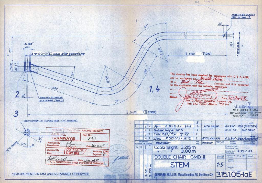
136
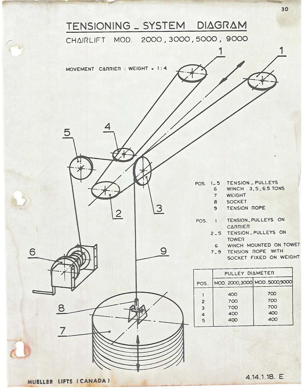
137
138
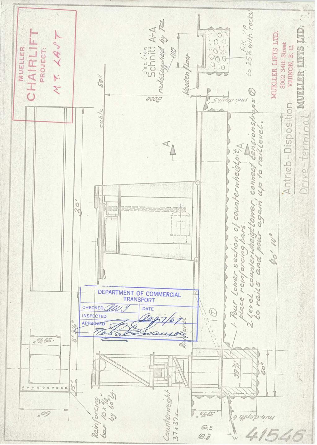
139
Chapter 2 Rigging. Cutting Wire Rope. Anchoring Wire Rope to Drum. Winding Wire Rope Onto Drum
 Chapter 2 Rigging Cutting Wire Rope The wire rope must be tightly seized on both sides of the point where the wire rope will be cut, as shown in Figure 2-1. Seize the wire rope with either seizing wire
Safe Work Practices (SWP) SWP (6) FALL PROTECTION PROGRAM
 SWP (6) FALL PROTECTION PROGRAM") SWP (6) FALL PROTECTION PROGRAM The following information on Fall Protection has been based around the BC OHS Regulations, standards, policies and guidelines. Prior to starting work outside of BC, the
SWP (6) FALL PROTECTION PROGRAM The following information on Fall Protection has been based around the BC OHS Regulations, standards, policies and guidelines. Prior to starting work outside of BC, the
SQUAW VALLEY FUNITEL
 SQUAW VALLEY FUNITEL AN INSTALLATION FOR THE THIRD MILLENNIUM Co presentation: Ernst Egli, PE Hans Burkhart Director for Marketing and Sales Gen. Manager Garaventa AG Squaw Valley Ski Corp. Switzerland
INSTALLATION PROCEDURE FOR OPGW FIBER OPTIC CABLES
 Page 1 of 15 INSTALLATION PROCEDURE FOR OPGW FIBER OPTIC CABLES Page 2 of 15 1. PURPOSE 2. SCOPE 3. REFERENCES 4. GENERAL INDEX 5. PROCEDURES 5.1 Line survey 5.2 Transport, loading, unloading and storage
PHASE 1 WIND STUDIES REPORT
 PHASE 1 WIND STUDIES REPORT ENVIRONMENTAL STUDIES AND PRELIMINARY DESIGN FOR A SUICIDE DETERRENT SYSTEM Contract 2006-B-17 24 MAY 2007 Golden Gate Bridge Highway and Transportation District Introduction
WARNING! DO NOT THROW AWAY THESE INSTRUCTIONS! READ AND UNDERSTAND BEFORE USING EQUIPMENT!
 Guardian Fall Protection Kent, WA 800-466-6385 www.guardianfall.com GENERAL SYSTEM SELECTION CRITERIA: Selection of fall protection shall be made by a Competent Person. All fall protection equipment shall
GUIDELINES FOR USE GUARD
 GUIDELINES FOR USE GUARD G Guard Range of Load Arrestors Retractable Fall Arrest Safety Line for Protection of Machinery & Sensitive Loads GLOBESTOCK MILE OAK INDUST. ESTATE, MAESBURY ROAD, OSWESTRY, SHROPSHIRE
WARNING! DO NOT THROW AWAY THESE INSTRUCTIONS! READ AND UNDERSTAND BEFORE USING EQUIPMENT!
 Guardian Fall Protection Kent, WA 800-466-6385 www.guardianfall.com GENERAL SYSTEM SELECTION CRITERIA: Selection of fall protection shall be made by a Competent Person. All fall protection equipment shall
Crane Rental Heavy Machinery Moving Project Management
 2 3 4 5 6 7 8 9 10 Link-Belt TG-2300B lifting crane capabilities - heavy duty boom Boom - tubular: 90" x 90" (2.29 x 2.29 m) with open throat top section, 2" (51 mm) diameter boom pendants. Mast - 43'
CRANE WITH WINCH USE AND MAINTENANCE MANUAL. Code Rev. Release MD /03
 CRANE WITH WINCH Code Rev. Release MD.0.097 0 06/03 USE AND MAINTENANCE MANUAL CONTENTS 1 FOREWORD page 3 1.1 Description of the crane with winch page 3 2 USE OF THE CRANE WITH WINCH page 3 2.1 General
FALL PROTECTION GUIDELINE
 FALL PROTECTION GUIDELINE July 2001 Table of Contents INTRODUCTION...3 CONTROL MEASURES...4 SURFACE PROTECTION...4 FIXED BARRIERS...5 EXAMPLES OF GUARDRAIL...6 WARNING BARRIERS...7 HANDRAILS...8 SURFACE
You may order this publication from WCB Publications and Videos, Please quote ordering number BK60.
 The following material is the property of the Workers Compensation Board of British Columbia and may not be reproduced by those outside of B.C. For those within British Columbia, this material may only
VL 2K LIFT D-L WINCH INSTRUCTIONS (Applies to P/Ns , , , , , )
") VL 2K LIFT D-L WINCH INSTRUCTIONS (Applies to P/Ns 3714022, 3714028, 3714034, 3714040, 3714043, 3714046) REIMANN & GEORGER CORPORATION MARINE PRODUCTS BUFFALO, NY P/N 6112103 04/09/18 1 SAFETY 1.1 INTRODUCTION
VL 2K LIFT D-L WINCH INSTRUCTIONS (Applies to P/Ns 3714022, 3714028, 3714034, 3714040, 3714043, 3714046) REIMANN & GEORGER CORPORATION MARINE PRODUCTS BUFFALO, NY P/N 6112103 04/09/18 1 SAFETY 1.1 INTRODUCTION
DEFINITIONS ROPE ACCESS
 DEFINITIONS G34.1 Definitions Boatswain's (Bosun's) chair ROPE ACCESS G34.4(1)(a) Training and certification G34.4(1)(b) Certification for Professional Mountain Guides and Climbing Gym Instructors G34.5
WINSAFE Corp. Operating Instructions For Outrigger Davit. Winsafe Part # WSOR208
 WINSAFE Corp. Operating Instructions For Outrigger Davit Winsafe Part # WSOR208 These instructions must be read and understood by anyone installing or suspending equipment from Winsafe modular beams and
DIRECT DRIVE DIXIE DOUBLE SEAMER Model 25D
 OPERATOR'S MANUAL DIRECT DRIVE DIXIE DOUBLE SEAMER Model 25D LUBRICATE DAILY: A. Gears inside gear housing at chuck shaft (1) Oil B. Seam rolls and cam rolls (4) - Oil C. Seam roll levers through gear
Ground Fault Circuit Interrupter(GFCI) Policy
 Policy") NewStar Netronics, LLC American Products for the World Ground Fault Circuit Interrupter(GFCI) Policy 3926 East 3 rd Street Tulsa, OK 74112 Phone (918)894-5006 Fax (918)836-9909 tech@newstarnetronics.com
NewStar Netronics, LLC American Products for the World Ground Fault Circuit Interrupter(GFCI) Policy 3926 East 3 rd Street Tulsa, OK 74112 Phone (918)894-5006 Fax (918)836-9909 tech@newstarnetronics.com
Warning CABLE REPLACEMENT INSTRUCTIONS. Questions? - Call Telpro Inc. Customer Service at or
 CABLE REPLACEMENT INSTRUCTIONS Warning Read and follow these warnings and the instructions that follow. Failure to do so could result in serious property damage and/or serious bodily injury. BEFORE operating
Taiwan Bicycle Industry Standard
 Taiwan Bicycle Industry Standard TBIS 4210-9 First edition 2016.01.01 Cycles Safety requirements for bicycles Part 9: Saddles and seat post test methods Reference number: TBIS 4210-9:2015 (FDTS) Contents
Operator's Manual Supplement
 Operator's Manual Supplement Traveling Fall Arrest Anchor System Original Instructions First Edition Fifth Printing Part No. 1256390GT Operator's Manual Supplement Genie Self-propelled Boom Products and
Appointed person Note: It is recommended that you read the Supporting Information page before you read this factsheet.
 Appointed person Note: It is recommended that you read the Supporting Information page before you read this factsheet. Planning and regulatory requirements (Regulatory requirements) The role or duties
GUIDELINES FOR USE -GUARD
 GUIDELINES FOR USE -GUARD G-Guard Range of Load Arresters Retractable able Fall Arrest Safety Line for Protection on of Machinery & Sensitive Loads Directive 2006/42/EC GLOBESTOCK Ltd MILE OAK INDUST.
User Instructions 1790 Rail Anchor
 User Instructions 1790 Rail Anchor This document is intended to meet the Manufacturer s Instruction requirements as stated by ANSI Z359.1, and should be used as part of an employee training program as
The purpose of this training is to give field technicians awareness training and guidelines on potential hazards they may encounter in the field.
 Purpose The purpose of this training is to give field technicians awareness training and guidelines on potential hazards they may encounter in the field. Fall Protection and Prevention JELD-WEN Field Employees
User Instructions 1789 Parapet Wall Anchor
 User Instructions 1789 Parapet Wall Anchor This manual is intended to meet the Manufacturer Instructions as required by ANSI Z359.1 and should be used as part of an employee training program as required
Load Charts Annotated Instructor s Guide. Module MODULE OVERVIEW PREREQUISITES OBJECTIVES PERFORMANCE TASKS MATERIALS AND EQUIPMENT LIST
 Load Charts Annotated Instructor s Guide Module 21301-05 MODULE OVERVIEW This module discusses the importance of load charts and charts that apply to different configurations. It includes on-rubber, on-outrigger,
CPCS renewal test factsheet
 CPCS renewal test factsheet Introduction to the CPCS renewal test The industry-led CPCS Management Committee has determined that key safety-related knowledge must be checked on each category prior to the
Crane & Rigging Brain Teasers
 Crane & Rigging Brain Teasers Host: Mike Parnell President/CEO, ITI ASME B30 Vice Chair (Cranes & Rigging) ASME P30 Chair (Lift Planning) The views expressed in this presentation are that of ITI and are
APPLYING VARIABLE SPEED PRESSURE LIMITING CONTROL DRIVER FIRE PUMPS. SEC Project No
 APPLYING VARIABLE SPEED PRESSURE LIMITING CONTROL DRIVER FIRE PUMPS SEC Project No. 1803007-000 November 20, 2006 TABLE OF CONTENTS I. ABSTRACT...1 II. INTRODUCTION...1 III. HISTORY...2 IV. VARIABLE SPEED
Thank you for purchasing a Porta-Dock product! *Please read and follow these instructions step by step*
 PG 1 OF 9 PORTA-DOCK, INC. 74A ABL/APW 1056 & 44A FLB APW 1056 PORTA-LIFT Thank you for purchasing a Porta-Dock product! *Please read and follow these instructions step by step* STEP 1. Separate and group
Confined Spaces. County of Henrico Risk Management Loss Prevention October 2 nd 2013
 Confined Spaces County of Henrico Risk Management Loss Prevention October 2 nd 2013 Standard Permit-Required Confined Spaces 29 CFR 1910.146 Confined Space Confined space is space that: Is large enough
User Instruction Manual Fixed Beam Anchor
 Instructions for the following series products: FIXED BEAM ANCHOR Model Numbers: The Ultimate in Fall Protection 2108406 2108407 2108408 2108409 2108410 2108411 User Instruction Manual Fixed Beam Anchor
RESOLUTION A.1045(27) RECOMMENDATION ON PILOT TRANSFER ARRANGEMENTS
 RECOMMENDATION ON PILOT TRANSFER ARRANGEMENTS") RESOLUTION A.1045(27) RECOMMENDATION ON PILOT TRANSFER ARRANGEMENTS 1 GENERAL Ship designers are encouraged to consider all aspects of pilot transfer arrangements at an early stage in design. Equipment
RESOLUTION A.1045(27) RECOMMENDATION ON PILOT TRANSFER ARRANGEMENTS 1 GENERAL Ship designers are encouraged to consider all aspects of pilot transfer arrangements at an early stage in design. Equipment
Fall Protection Checklist. Guardrail System
 Fall Protection Checklist Location/Department: Date of Inspection: Inspectors: Corrective Actions: Work order/memos were issued: Yes No Date issued: In accordance with the MIOSHA and OSHA standards the
DEPARTMENT OF LICENSING AND REGULATORY AFFAIRS CORPORATIONS, SECURITIES, AND COMMERCIAL LICENSING BUREAU SKI AREA SAFETY - GENERAL RULES
 DEPARTMENT OF LICENSING AND REGULATORY AFFAIRS CORPORATIONS, SECURITIES, AND COMMERCIAL LICENSING BUREAU SKI AREA SAFETY - GENERAL RULES (By authority conferred on the director of the department of licensing
MANUFACTURING TECHNICAL INSTRUCTIONS - SAFETY FALL HAZARD CONTROL REQUIREMENTS SERIES & NO. SMI - 157
 1 of 6 1.0 PURPOSE To establish minimum requirements and guidelines for controlling hazardous exposure of personnel to falls from working elevations in conformance with Federal and State OSHA rules and
Product Guide. Crawler Crane
 Crawler Crane 220 US Tons (100 Metric Tons) @ 16 ft 5 in Radius 285 ft Max Tip (Main Boom) Main Boom, Fixed Jib and Luffing Jib Configurations Product Guide KEY FEATURES ULTRA CAB The Ultra Cab, designed
CONFINED SPACE ENTRY PROGRAM
 CONFINED SPACE ENTRY PROGRAM 2003 ENVIRONMENTAL HEALTH AND SAFETY/RISK MANAGEMENT p1 Rev. 01/07/2003 wrk Environmental Health and Safety/Risk Management CSUCI Confined Space Entry Program TABLE OF CONTENTS
MEWP - Boom Note: It is recommended that you read the Supporting Information page before you read this factsheet.
 MEWP - Boom Note: It is recommended that you read the Supporting Information page before you read this factsheet. Preparation for work (Preparation) Boom-type mobile elevated work platforms, commonly known
Requirements for Reduced Supervision of Power Plants, Thermal Liquid Heating Systems, and Heating Plants
 the pressure equipment safety authority Requirements for Reduced Supervision of Power Plants, Thermal Liquid Heating Systems, and Heating Plants AB-528 Edition 2, Revision 1 Issued 2016-09-12 Table of
MUELLER A A Non-Adjustable. Vertical Indicator Posts. Reliable Connections. General Information 2. Technical Data 3.
 Installation Instructions manual MUELLER table of contents PAGE A-20808 General Information 2 Technical Data 3 Dimensions 4 A-20809 Non-Adjustable Installation 5-6 Parts 7 Maintenance 8 Vertical Indicator
Region: USA Language: EN Number : TB0031 Revision : B. Total Page: 3 Page n : 1 First Issue: 10/2014 Rev. Date: 10/08/2014
 Subject Dropped Object Protection Region: USA Language: EN Number : TB0031 Revision : B Total Page: 3 Page n : 1 First Issue: 10/2014 Rev. Date: 10/08/2014 Some users of fall protection equipment require
STATISTICAL SUMMARY RAILWAY OCCURRENCES 2015
 STATISTICAL SUMMARY RAILWAY OCCURRENCES 215 April 216 Transportation Safety Board of Canada Place du Centre 2 Promenade du Portage, 4th floor Gatineau QC K1A 1K8 819-994-3741 1-8-387-3557 www.tsb.gc.ca
EXHIBIT A FALL PROTECTION POLICY
 EXHIBIT A FALL PROTECTION POLICY Table of Contents I. Statement of Company Policy... 3 II. Fall Protection Systems to Be Used on This Project... 4 Safety Monitoring System... 5 Control Zone System... 5
Fiber Cable Puller with Tuf-Lugger lite
 7 OPERATING INSTRUCTION MANUAL Fiber Cable Puller with Tuf-Lugger lite Copyright 2015 DCD Design & Manufacturing Ltd. Revision 1.0 IMPORTANT SAFETY INSTRUCTIONS READ ALL INSTRUCTIONS BEFORE USING The Fiber
Assembly, Installation and operating. instructions for. Söll-Xenon anchorage device
 Assembly, Installation and operating instructions for Söll-Xenon anchorage device according to EN 795:1996 Part No: XE-... (The following must be completed by the operator in permanent waterproof ink.)
FALL PROTECTION. Leader s Guide. Marcom Group Ltd.
 1818 FALL PROTECTION Leader s Guide Marcom Group Ltd. Structure and Organization Information in this program is presented in a definite order, so that employees will see the relationships between the various
CPCS renewal test factsheet
 CPCS renewal test factsheet Introduction to the CPCS renewal test The industry-led CPCS Management Committee has determined that key safety-related knowledge must be checked on each category prior to the
BSR GPTC Z TR GM References and Reporting Page 1 of 8
 Page 1 of 8 PRIMARY: 192.605 SECONDARY: 191.23 PURPOSE: Review guide material added by TR 2009-17 to 5.1(e) and consider restructuring the guide material under 192.605 as discussed further below. ORIGIN/RATIONALE
City of Los Angeles Department of Building & Safety Disabled Access Section Supplemental Plan Review Checklist No. 8 RECREATION FACILITIES
 AMUSEMENT RIDES, BOAT SLIPS, BOWLING LANES, COURT SPORTS, FISHING PIERS Plan Check No. 1. Amusement rides required to comply with 11B-234, Amusement Rides shall provide accessible routes in accordance
Care, Use & Maintenance of Wire Ropes on Cranes
 Care, Use & Maintenance of Wire Ropes on Cranes Dr. Frank Jauch Global Product Manager Crane Ropes WireCoWorldGroup Kansas City/MO USA Our partner in Australia The company was founded in 1948 CASAR Ropes
Chapter 5 Site Considerations and Set-ups Table of Contents
 WI-750-074 Rev C Page 1 of 9 Chapter 5 Site Considerations and Set-ups Table of Contents 1. PURPOSE... 1 2. SCOPE... 2 3. DEFINITIONS... 2 4. ASSOCIATED DOCUMENTS... 2 5. SITE CONSIDERATIONS... 2 5.1.
OPERATIONS and SAFETY MANUAL
 OPERATIONS and SAFETY MANUAL LIFETIME WARRANTY SPECIAL SAFETY FEATURES: 1. Hook starts to open when device exceeds weight limit. 2. Latch Pops when weight is exceeded. At this point remove the load from
Fire Apparatus Operator Aircraft Rescue and Fire Fighting
 Fire Apparatus Operator Aircraft Rescue and Fire Fighting Skill Sheet Package Based on NFPA 1002: Standard on Fire Apparatus Driver/ Operator Professional Qualifications, 2014 Edition. Alabama Fire College
Wafer Check Valve. Contents. User s Manual. (1) Be sure to read the following description of our product warranty 1
 Be sure to read the following description of our product warranty 1") Serial No. H-V066-E-3 Wafer Check Valve User s Manual Contents (1) Be sure to read the following description of our product warranty 1 (2) General operating instructions 2 (3) General instructions for
Serial No. H-V066-E-3 Wafer Check Valve User s Manual Contents (1) Be sure to read the following description of our product warranty 1 (2) General operating instructions 2 (3) General instructions for
LOAD CHARTS RT890E METRIC DIN / ISO / 75%
 LOAD CHARTS RT89E METRIC DIN / ISO / 75% 232729 SERIAL NUMBER RT89E - S/N 232729 1 RT89E - S/N 232729 2 TABLE OF CONTENTS GENERAL NOTES...4 WEIGHT REDUCTIONS / LINE PULLS & REEVING INFO / RIGGING CHART
GEMTOR. ... when your life is on the line OWNER'S MANUAL. FLW Series Self-Retracting Lanyard/Fall Limiter
 GEMTOR TM... when your life is on the line OWNER'S MANUAL FLW Series Self-Retracting Lanyard/Fall Limiter Installation, Operating, Inspection and Maintenance Instructions Warning You must read and fully
CONFINED SPACE POLICY
 Policy No. 6 THE CITY OF POMONA SAFETY POLICIES AND PROCEDURES CONFINED SPACE POLICY City Manager I. PURPOSE The purpose of the City of Pomona Confined Space Policy is to ensure that employees are adequately
USER MANUAL. JET TST and JET TST S.
 USER MANUAL JET TST and JET TST S www.sisteven.com Types of Jet fans: JET TST UNI: Impulse axial fan single direction JET TST S UNI: Impulse axial fan single direction (short case) JET TST REV: Impulse
PRESSURE SYSTEMS POLICY
 PRESSURE SYSTEMS POLICY PRESSURE SYSTEMS POLICY 1. Introduction 2. Policy Statement 3. Scope 4. Background 5. Roles & Responsibilities 6. Training 7. Contractors 8. Policy Review 1. Introduction The Kilmarnock
unconventional-airsoft.com
 unconventional-airsoft.com Congratulations on your new digital fire control computer! This unit will change the way you use and look at your electric gun. With this short document, you will know all you
Safewaze FS983 Cable Safety Climb System Ladder Mount Instructions
 Safewaze FS983 Cable Safety Climb System Ladder Mount Instructions Ladder Mount Cable Safe Climb System B) Head Assembly with Cable A) Upright Mast C) Cable Standoff E) Cable Clamps D) Base Anchor Bracket
Module 3 Developing Timing Plans for Efficient Intersection Operations During Moderate Traffic Volume Conditions
 Module 3 Developing Timing Plans for Efficient Intersection Operations During Moderate Traffic Volume Conditions CONTENTS (MODULE 3) Introduction...1 Purpose...1 Goals and Learning Outcomes...1 Organization
Operating instruction
 Operating instruction MV, XV, HG, HP, RKO, D2G, TV, BV, WB & SLV 1 Introduction 2 2 Stafsjö s knife gate valves 2 3 Technical information 2 3.1 Pressure test 2 3.2 Labelling 2 4 Storage 3 5 Transportation
HOT OILING OPERATIONS ALL HSE PRC 172. Approved By: Manager, HSE Performance Assurance. Table of Contents
 Owner: HSE Performance Assurance ALL HSE PRC 172 Approved By: Manager, HSE Performance Assurance Retention Code: CG01 CA Revised: March 2015 Review Frequency: Five years or less Table of Contents 1.0 Purpose...
CHAPTER 5: GENERAL SITE AND BUILDING ELEMENTS
 CHAPTER 5: GENERAL SITE AND BUILDING ELEMENTS 501 General 501.1 Scope. The provisions of Chapter 5 shall apply where required by Chapter 2 or where referenced by a requirement in this document. 502 Parking
General Inspection Guidance for Waste Management Units Requiring Air Emission Controls Under RCRA Air Standard Subpart CC
 United States Environmental Protection Agency RCRA Programs Branch Region IV Atlanta, GA CAA/RCRA Air Rules 27 November 2000 General Inspection Guidance for Waste Management Units Requiring Air Emission
New Mexico Institute of Mining & Technology. Fall Protection Program
 New Mexico Institute of Mining & Technology Fall Protection Program REGULATORY STANDARDS: OSHA - 29 CFR 1910.66 29 CFR 1910.128, 129, 130, 131, (Proposed) 29 CFR 1926.104 29 CFR 1926.500 BASIS: Approximately
Ropes for Subsea Cable Laying
 Ropes for Subsea Cable Laying SEAMASTER CABLE LAID BUOY & GRAPNEL ROPES [ BUOY & GRAPNEL ] Cable Laid combined (wire and natural fibre) ropes specially designed for Subsea Cable Laying duties Designed
BRAKE WINCH RUP 503-[T/BT] EQUIPMENT FOR LIFTING LOADS. AT 053-[T/BT] xx
![BRAKE WINCH RUP 503-[T/BT] EQUIPMENT FOR LIFTING LOADS. AT 053-[T/BT] xx](/thumbs/88/115945274.jpg "BRAKE WINCH RUP 503-[T/BT] EQUIPMENT FOR LIFTING LOADS. AT 053-[T/BT] xx") Reference number: BRAKE WINCH RUP 503-[T/BT] EQUIPMENT FOR LIFTING LOADS DESIGNATED USE The brake winch RUP 503-[...]T series is a load lifting / lowering device. Device is equipped with safety brake for
Reference number: BRAKE WINCH RUP 503-[T/BT] EQUIPMENT FOR LIFTING LOADS DESIGNATED USE The brake winch RUP 503-[...]T series is a load lifting / lowering device. Device is equipped with safety brake for
Fire Apparatus Operator: ARFF
 Fire Apparatus Operator: ARFF Skill Sheet Package Based on NFPA 1002: Standard on Fire Apparatus Driver/ Operator Professional Qualifications, 2017 Edition. Alabama Fire College November 26, 2018 Alabama
E02 Rigid hinged stinger with piggyback line
 E02 Rigid hinged stinger with piggyback line This model represents a rigid stinger hinged off the back of a lay vessel using the pipelay supports feature. In addition to the lay pipe, another line is included
Installation and Training Manual
 AirForce1 Tower Kit Installation and Training Manual FuturEnergy Limited Ettington Park Business Centre Stratford upon Avon CV37 8BT +44 (0)1789 451070 Table of Contents Safety Notes... 3 Parts Supplied
1. Objective of the initiative To ensure that all employees and subcontractors are aware of the risks associated with working at height.
 Safety Initiative 02 Working at Height May 2011 CONTENTS 1. Objective of the initiative 2. Overview. 3. Implementation 4. Duties 5. Hierarchy of Controls 6. Workplace Inspections 7. Fragile Surfaces 8.
MUELLER. A A Adjustable. Vertical Indicator Posts. Reliable Connections. General Information 2. Technical Data 3.
 Installation Instructions manual MUELLER table of contents PAGE A-20806 A-20807 Adjustable General Information 2 Technical Data 3 Dimensions 4 Installation 5-6 Parts 7 Maintenance 8 Vertical Indicator
Overview (key points)
") Topic / Subject TYPE 1 FALL-ARREST DEVICES Time frame = mins Contact statement (gain student attention and create a readiness to learn) Overview (key points) Purpose -Fall-arrest devices are designed to
Topic / Subject TYPE 1 FALL-ARREST DEVICES Time frame = mins Contact statement (gain student attention and create a readiness to learn) Overview (key points) Purpose -Fall-arrest devices are designed to
Installation Drawings & Instructions Fall Protection Systems
 ISO 9001 Registered Installation Drawings & Instructions Fall Protection Systems Attach the Cougar Slider only at this Sternum Connection Point CSA Z259.2.1-98 & ANSI Z359.1-M1992 [Canada & USA] Revision
Assignment 1 Unit 3 Work, Power, Efficiency, and Potential Energy Name: Multiple Choice. Show workings where necessary.
 Assignment 1 Unit 3 Work, Power, Efficiency, and Potential Energy Name: Multiple Choice. Show workings where necessary. 1. In which situation is work not done? A) a frozen turkey is carried upstairs B)
PACKSETTER HAND PUMP
 PACKSETTER HAND PUMP 1 CONTENTS Introduction...3 1. Product Description 3 2. Design Criteria.. 3 3. Risk Assessment Team.. 3 4. Objectives... 4 5. Hazard Classification...4+5 Risk matrix..6 FACTOR/INDEX
Sizing of extraction ventilation system and air leakage calculations for SR99 tunnel fire scenarios
 Sizing of extraction ventilation system and air leakage calculations for SR99 tunnel fire scenarios Yunlong (Jason) Liu, PhD, PE HNTB Corporation Sean Cassady, FPE HNTB Corporation Abstract Extraction
User Instruction Manual Fixed Beam Anchor
 User Instruction Manual Fixed Beam Anchor This manual is intended to meet the Manufacturer s Instructions as required by ANSI Z359.1 and ANSI A10.14, and should be used as part of an employee training
OMG Southeast & Southwest RIGGING SAFETY PROGRAM (29 CFR Part , , , , , & ANSI B30.5, ANSI B30.
 OMG Southeast & Southwest RIGGING SAFETY PROGRAM (29 CFR Part 1926.251, 1926.550, 1910.180, 1910.184, 1910.330, & ANSI B30.5, ANSI B30.8) Nearly every project is required to perform some type of rigging
INFLUENCE OF VOLCANIC ASH ON FATIGUE LIFE OF STEEL WIRE ROPES
 INFLUENCE OF VOLCANIC ASH ON FATIGUE LIFE OF STEEL WIRE ROPES Authors: Matías Cersósimo / IPH, Buenos Aires, Argentina / mcersosimo@iph.com.ar Jorge López-Digon / INTI, Buenos Aires, Argentina / jdigon@inti.gob.ar
Hand winch MANIBOX GR
 Hand spurgear winch Hand winch MANIBOX GR Instruction manual UK 34-331.09/9 PRODUCT DEVELOPED AND MANUFACTURED ACCORDING TO STANDARD NF EN 13157 In an endeavour to improve its products, HUCHEZ reserves
SERVING MANUFACTURERS, DISTRIBUTORS & RELATED SERVICE PROVIDERS FOR THE MATERIAL HANDLING INDUSTRY SINCE
 June 2017 www.wireropenews.com SERVING MANUFACTURERS, DISTRIBUTORS & RELATED SERVICE PROVIDERS FOR THE MATERIAL HANDLING INDUSTRY SINCE 1979 June is National Safety Month! Safety is the Main Concern Preventing
Apex Evaporator Manual
 Apex Evaporator Manual Table of Contents I. Handling/Transportation of Apex II. Placing the evaporator III. Connecting Power to the control Panel IV. Placing the control panel and weather station V. Attaching
GROVE MODEL RT58D - 20 TON CAPACITY
 LIFTING CHARTS - Rough Terrain Cranes GROVE MODEL - 20 TON CAPACITY WEIGHT REDUCTIONS FOR LOAD HANDLING DEVICES 23 JIB with 28-70 BOOM * Stowed - 381 lbs. * Erected - 1,950 lbs. 23-38 TELE. JIB with 28-70
SIMON Simulation of Non-Automotive Vehicle Free Rolling Response
 SIMON Simulation of Non-Automotive Vehicle Free Rolling Response Ciro Ramirez, PhD, PE, CSHO, C. L. Long, Jr., P.E., and R. Joe Thornhill, PhD, PE, CSHO Thornhill, Ramirez & Associates, Inc. Copyright
Moor, Tend Mooring And Unmoor Ship - Supervisor Level -
 Marine Terminal Operations Competency Standard Moor, Tend Mooring And Unmoor Ship - Supervisor Level - Industry : Oil, Chemical and Gas Industry Competency Category : 2.0 Moor, tend mooring and unmoor
National Cave Rescue Commission Level 3 Student Preparation Guide
 National Cave Rescue Commission Level 3 Student Preparation Guide NCRC requires all students demonstrate basic skills prior to participation. Level 3 students will be tested on knot tying, single rope
HOW TO PREPARE FOR THE LEVEL A CRANESAFE CERTIFICATION ASSESSMENT
 HOW TO PREPARE FOR THE LEVEL A CRANESAFE ASSESSMENT Prepare for your assessment! Our website contains all the information you need for a successful assessment. Our goal is to find you competent on the
 www.brugglifting.com Recommended Hoist Rope Handling Procedures Transport Storage Show caution when transporting hoist ropes as they can be damaged on forklift forks. Try to eliminate direct physical contact
Assembly Instructions. -Cantilever Boat Lifts
 Assembly Instructions -Cantilever Boat Lifts Winch Instruction Page Safety Information 1. The winch is built for the multipurpose of hauling and lifting operations. It is not to be used as a hoist for
LOAD CHARTS RT540E 85% STABILITY ON OUTRIGGERS 75% STABILITY ON RUBBER
 LOAD CHARTS RT540E 85% STABILITY ON OUTRIGGERS 75% STABILITY ON RUBBER SERIAL NUMBER 1 2 TABLE OF CONTENTS GENERAL NOTES... 4 WT. REDUCTIONS / LINE PULLS & REEVING INFO / HOIST PERFORMANCE. 5 LIFTING AREA
PLANNED LIGHTING MAINTENANCE LTD METHOD STATEMENT & RISK ASSESSMENT REPLACEMENT OF LAMPS OR REPAIRS TO HIGH LEVEL LIGHT UNITS
 PLANNED LIGHTING MAINTENANCE LTD METHOD STATEMENT & RISK ASSESSMENT REPLACEMENT OF LAMPS OR REPAIRS TO HIGH LEVEL LIGHT UNITS Project: (insert Client) Replacement/ Repair of high level light units/ high
Installation, Operating, Inspection and Maintenance Instructions Ladder Climber s Safety System. Warning
 OWNER'S MANUAL Installation, Operating, Inspection and Maintenance Instructions Ladder Climber s Safety System Model # s: 6000, 6001, 6010 Warning You must read and fully understand all instructions, or
A A A T E C H N O L O G Y
 A A A T E C H N O L O G Y & SPECIALTIES CO., INC. C O N S T A N T E F F O R T S U P P O R T S TOTAL SOLUTION SERVICE For the Industrial Piping Marketplace 2012 www.aaatech.com 4 1 Y E A R S S E R V I N
Standard Operating Procedures
 Standard Operating Procedures GlassBore and GlassLine EUE 8RD Tubular Goods Composite Lining Systems Focus on Safety and Quality COMPOSITE LINING SYSTEMS Table of Contents Section 1 page 3 Arrival on Production
Annex D (normative) Signs
 Signs") Annex D (normative) Signs NOTE There are signs in this normative reference that are informative and not required (see D.2). D.1 Signs on Ropeways See the sign subclause (2.3.1.2, 3.3.1.2, 4.3.1.2, 5.3.1.2,
Annex D (normative) Signs NOTE There are signs in this normative reference that are informative and not required (see D.2). D.1 Signs on Ropeways See the sign subclause (2.3.1.2, 3.3.1.2, 4.3.1.2, 5.3.1.2,
OPERATIONS MANUAL IMPORTANT SAFETY INFORMATION
 OPERATIONS MANUAL IMPORTANT SAFETY INFORMATION Please read, understand and follow all safety information contained in these instructions prior to the use of this tool. Retain these instructions for further