Robotic Augmentation. Of Human Locomotion. For High Speed Running. Jason Kerestes
|
|
|
- Kathleen Fitzgerald
- 6 years ago
- Views:
Transcription
1 Robotic Augmentation Of Human Locomotion For High Speed Running by Jason Kerestes A Thesis Presented in Partial Fulfillment of the Requirements for the Degree Master of Science Approved November 2014 by the Graduate Supervisory Committee: Thomas Sugar, Chair Sangram Redkar Bradley Rogers ARIZONA STATE UNIVERSITY December 2014
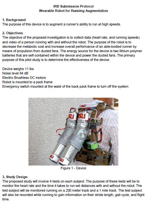
2 ABSTRACT Human running requires extensive training and conditioning for an individual to maintain high speeds (greater than 10mph) for an extended duration of time. Studies have shown that running at peak speeds generates a high metabolic cost due to the use of large muscle groups in the legs associated with the human gait cycle. Applying supplemental external and internal forces to the human body during the gait cycle has been shown to decrease the metabolic cost for walking, allowing individuals to carry additional weight and walk further distances. Significant research has been conducted to reduce the metabolic cost of walking, however, there are few if any documented studies that focus specifically on reducing the metabolic cost associated with high speed running. Three mechanical systems were designed to work in concert with the human user to decrease metabolic cost and increase the range and speeds at which a human can run. The methods of design require a focus on mathematical modeling, simulations, and metabolic cost. Mathematical modeling and simulations are used to aid in the design process of robotic systems and metabolic testing is regarded as the final analysis process to determine the true effectiveness of robotic prototypes. Metabolic data, (VO2) is the volumetric consumption of oxygen, per minute, per unit mass (ml/min/kg). Metabolic testing consists of analyzing the oxygen consumption of a test subject while performing a task naturally and then comparing that data with analyzed oxygen consumption of the same task while using an assistive device. Three devices were designed and tested to augment high speed running. The first device, AirLegs V1, is a mostly aluminum exoskeleton with two pneumatic linear actuators connecting from the lower back directly to the user's thighs, allowing the device i
3 to induce a torque on the leg by pushing and pulling on the user s thigh during running. The device also makes use of two smaller pneumatic linear actuators which drive cables connecting to small lever arms at the back of the heel, inducing a torque at the ankles. Device two, AirLegs V2, is also pneumatically powered but is considered to be a soft suit version of the first device. It uses cables to interface the forces created by actuators located vertically on the user's back. These cables then connect to the back of the user s knees resulting in greater flexibility and range of motion of the legs. Device three, a Jet Pack, produces an external force against the user's torso to propel a user forward and upward making it easier to run. Third party testing, pilot demonstrations and timed trials have demonstrated that all three of the devices effectively reduce the metabolic cost of running below that of natural running with no device. ii
4 TABLE OF CONTENTS Page LIST OF TABLES... iv LIST OF FIGURES... v CHAPTER 1 INTRODUCTION Force Effects on Humans Running Over Ground Requirements of Control Systems History of Exoskeletons Objectives Hypothesis Thesis Outline GAIT EXPLORATION Human Gait Cycle Pulling Forces Needed for Augmentation OpenSim Modeling CONTROLLER METHODOLOGY Phase Oscillator Phase Controller DESIGN OF RUNNING AUGMENTATION DEVICES AirLegs V AirLegs V Jet Pack iii
5 CHAPTER Page 5 DEVICE EXPERIMENTATION AND ANALYSIS Army Research Laboratory Third Party Testing of AirLegs V AirLegs V2 Testing Jet Pack Testing CONCLUSIONS AND RECOMMENDATIONS REFERENCES APPENDIX A JET PACK IRB PROTOCOL AND CONSENT DOCUMENTATION iv
6 LIST OF TABLES Table Page 5.1 Metabolic Cost When Running With Powered Hips on Treadmill at ARL Speed and Heart Rate With and Without Jet Pack v
7 LIST OF FIGURES Figure Page 1.1 Three Devices with Forces Shown in Red Arrows Forces Acting on the Runner Propulsive Power Needed to Run Versus Braking Power Metabolic Cost Versus Applied Horizontal Force Apparatus for Facilitating Walking, Running, and Jumping Hardiman Designed by General Electric BLEEX Exoskeleton Designed by Berkeley Researchers Devices Designed to Augment Human Running The Walking Gait Cycle The running gait cycle Forces Acting on a Runner The Propulsive Power Needed to Run Versus the Breaking Power Testing Rig Attached to Electric Golf Cart Pull Force Testing with Golf Cart Rigging Pulling Test Subject While Recording Metabolic Pilot Data Speed Versus Pulling Force at 7mph Speed Versus Pulling Force at 9mph Speed Versus Pulling Force at 12mph Greatest Reduction in Metabolic Cost from 25 Degree Angle Metabolic Cost Free Running Versus Towed Running OpenSim 3D model of Muscular and Skeletal System vi
8 Figure Page 2.14 Muscle Activation Energy with and Without Towing/Thrust Force Phase Plot Definition System Position Oscillation Phase Plot Limit Cycle System Damps to Zero Phase Plot Position and Velocity Go to Zero Inverted Pendulum Oscillates Similar to Human Leg System Natural Frequency Damping Torque Oscillations Inverted Damping Torque Spring Torque Oscillations Rate Gyro Thigh Signal Phase Angle for Left and Right Leg Phase Angel and Control Signal for Left and Right Leg Phase Oscillator Control Software Written in Matlab Digilent Cerebot MC7 Microcontroller AirLegs V1 Left Back and Right Views AirLegs V1 Hip Joint Assembly Actuator Assembly Connected to Heel to Provide Torque at Ankle AirLegs V1 Gait Cycle AirLegs V2 Left Back and Right Views Jet Pack Left Back and Right Views vii
9 Figure Page 4.7 Jet Pack Back Pack Prototype Jet Pack Hand Held Controller Matlab Simulink Control Software for Jet Pack AirLegs V2 Metabolic Demonstration Subject Testing Jet Pack on 1 Mile Course Speed on 1 Mile Test With and Without Jet Pack Heart Rate on 1 Mile Test With and Without Jet Pack viii
10 CHAPTER 1 INTRODUCTION There are many methods to increase the speed and duration for which humans can travel. One common method for faster travel is through the use of wheeled vehicles, however, there are times when it would be beneficial for a person s natural ability to run to be augmented. When compared to common apparatuses such as wheeled vehicles, the human gait cycle allows for increased mobility where wheeled vehicles cannot travel due to incompatible terrain such as narrow passages, rocky terrain, or stairs. Although walking or running can allow for transportation of individuals through areas where wheeled vehicles cannot go, the duration of transportation and speed is heavily constrained by the physical capabilities of the human in question. Some individuals that are required to run for long distances at elevated speeds include infantry soldiers, police officers, fire fighters, and athletes. Individuals that would benefit from exceeding their natural physical capabilities are consistent with those that perform strenuous activities where physical performance directly relates to their overall success. In cases regarding military infantry, soldiers are often required to traverse long distances over rough terrain which can greatly impact their success in the battlefield (Fletcher, 1974). A robotic exoskeleton which augments human locomotion of the legs could increase a soldier's ability to accomplish strenuous missions, preserve cardiovascular performance leading to improved decision making, reduce the potential for injury due to over exertion, and enhance peak running speeds making a soldier faster than their enemies. The improved characteristics of soldiers using mechanical devices for augmentation could potentially result in the preservation of 1
11 human life when combined with strenuous, dangerous missions. For athletes, over-speed running and training has become popular using pulley systems and springs connecting two runners together (Behrens, 2011). Athletes could utilize mechanical devices to improve their performance in a variety of sports or could use devices for over-speed training so their capabilities are improved after using the device. Previous research has led to a variety of exoskeletons being developed that increase user strength; however, often times these devices are designed using hydraulics with a focus on generating extreme forces up to 5 times of what a human can naturally produce (Chu, 2005). This may create a very powerful system, but the systems are also heavy and slow, often increasing the metabolic cost of natural movement. Furthermore, if a system malfunction occurs, this could result in significant damage to the user due to the extreme forces the exoskeleton creates. The research contained within this thesis explores the application of light weight robotic systems which augment human locomotion for running at high speeds through a variety of actuators and application of external forces to a user. Furthermore, it explores the requirements of control systems to sense the user s movement for autonomous control and how properly timed control systems can inject energy into the human gait cycle. The systems designed to augment human running described in this thesis consist of two pneumatic devices (AirLegs V1 and V2) that apply torque at the hips and or ankles, and a Jet Pack that applies an external forward and upward force at the user's torso. 2

12 Figure 1.1. Three Devices with Forces Shown in Red Arrows, From Left to Right; AirLegs V1, AirLegs V2, Jet Pack 1.1 Force Effects on Humans Running Over Ground During the running gait cycle, the main external forces acting on the runner s motion are air drag and rolling friction. Figure 1.2. Forces Acting on the Runner The external forces acting on a runner, coupled with supporting the mass of the runner, are attributed to metabolic expenditure because the user s musculoskeletal system must overcome these forces to run at high speeds requiring significant amounts of oxygen. Furthermore, the metabolic cost associated with running has been shown to increase as relative running speeds increase (Gottschall, 2003). Three power curves based on the 3
13 runner's speed are demonstrated in figure 1.3. The rolling friction creates a large braking power proportional to weight. The power loss due to air drag is proportional to the cube of speed but is still smaller than frictional drag at high speeds (6.7 m/s or 15 mph). The total propulsive power must be equal to the total braking power plus drag power at high speeds which is reasonable for steady state motion. Figure 1.3. The Propulsive Power Needed to Run Versus the Braking Power Research also suggests that external forces significantly greater than the required propulsive force may not be optimal for reduction of metabolic cost in regards to the human gait cycle. One example of this is demonstrated in a study where different levels of an external force were applied to a user on a treadmill (Gottschall, 2003). An optimal metabolic reduction of 47% was determined when 10% of the user s body weight was applied as a forward force. In similar tests, this metabolic reduction was diminished as the forward force was increased above 10%, demonstrating that too much force was not beneficial. Thus, an exoskeleton or mechanical device designed to augment running must be comprised of lightweight components and offer the correct amount of assistance. If too much assistance is applied, the user's metabolic savings may diminish. 4
14 Figure 1.4. Metabolic Cost Versus Applied Horizontal Force (Gottshall, 2003) 1.2 Requirements of control systems To achieve autonomous control of a robotic exoskeleton, a control system must be designed in a way that enables the device to operate in concert with its user. This can be done by utilizing various sensors, switches, or user input (Ollinger, 2007). One problem that is often encountered when developing a control system in which a robot is to augment human locomotion is that if sensors are used to monitor limb movement, then applying forces to that limb adds impedance. This can cause the control system to lose stability because it is now manipulating its own input. Groups have attempted to address this issue by means of adding inertia compensation for more precise control; however this then leads to a delayed control system, especially if using force sensors that are not mounted closely to the physical interface of the user (Zanotto, 2013). Another approach to exoskeleton control is the use of a feed forward control system. Feed forward control systems have been used to compensate for the effects of gravity on a user s limbs but 5
15 these can quickly become unstable as well when coupled with the added inertia of an exoskeleton component combined with the user s limb. Furthermore, control systems designed to function based on negative damping of the user's limb, coupled with feed forward control and no inertia compensation, are likely to become unstable as well (Zanotto, 2013). Although there is no known research regarding high speed running and disturbances to the human body such as an exoskeleton becoming unstable or moving out of sync with the user, it is easy to imagine that a poor control system would cause the user to feel uncomfortable, especially with the risk of falling. It can also be assumed that if an exoskeleton is not perfectly in sync with the human i.e. significantly delayed or advanced actuators, the exoskeleton would not induce running augmentation because the user would be working against the robot for a portion of the gait cycle (Ollinger, 2007). 1.3 History of Exoskeletons The first recordings of exoskeleton type devices date back to the late 1800's when Nicholas Yagn began building what he called an "Apparatus for facilitating walking, running, and jumping" (Yagn, 1890). At the time, microprocessors had yet to be developed to control the device which resulted in a mostly passive apparatus; however, there were some pneumatic hand controls to activate artificial muscles. 6
16 Figure 1.5. Apparatus for Facilitating Walking, Running, and Jumping (Yagn, 1890) From information contained in a patent filled on February 11th 1890, Yagn developed an air powered device which was intended to utilize passive springs and cords to transfer momentum of the torso into energy for moving the feet at a higher rate of speed while carrying a load. Due to lack of documentation besides the patent which it was filed under, the success of this device cannot be determined. It was not until the mid 1960's that documentation of another exoskeleton device was published when General Electric developed and tested an exoskeleton named Hardiman (General Electric, 1968). 7
 The Hardiman device, a hydraulic full body exoskeleton, was designed to allow a user to manipulate extremely heavy objects up to 250lbs")
17 Figure 1.6. Hardiman Designed by General Electric (General Electric, 1968) The Hardiman device, a hydraulic full body exoskeleton, was designed to allow a user to manipulate extremely heavy objects up to 250lbs and consisted of a master-slave type approach to have the exoskeleton follow the movements of its pilot. Although they created a full scale prototype, the Hardiman project was eventually abandoned because the device was never capable of functioning properly due to weighing 1500lbs and limitations in sensing and actuator technology. When tested, the Hardiman would become violently out of control. Since the 1960's, advancements in technology have lead to many improvements in not only sensors, but hardware as well. With the development of the microprocessor in 1972 and continuous development thereafter, devices to assist human locomotion became much more practical (Ceruzzi, 2003). Within the last 10 years, exoskeleton type devices have become much more prevalent with many researchers developing their devices in conjunction with robotics. An example of an 8
 BLEEX applied torques to a user's hip, knee and ankle joints with hydraulic actuators which were powered through an onboard combustion")
18 exoskeleton using microprocessors and integrated sensors is the Berkeley Lower Extremity Exoskeleton (BLEEX). BLEEX was developed in 2001 and connects to a user s back and legs. Figure 1.7. BLEEX Exoskeleton Designed by Berkeley Researchers (Chu, 2005) BLEEX applied torques to a user's hip, knee and ankle joints with hydraulic actuators which were powered through an onboard combustion engine (Chu, 2005). The device was designed to follow the user s legs and support additional payload on the user's back. Lack of success of the device was attributed to the use of hydraulic systems and actuators that could not respond fast enough and the device was not effective for running. 1.4 Objective The objective of this thesis is to present alternative methods for augmentation of the human running gait through a variety of different robotic devices. Three devices have been designed, built, and tested to determine the most effective method for adding energy 9

19 into the human gait cycle and thereby reducing the metabolic cost associated with running at high speed. Figure 1.8. Devices Designed to Augment Human Running. From Left to Right, AirLegs V1, AirLegs V2, and Jet Pack Furthermore, the devices described in this thesis were designed to be as simple as possible to minimize the number of sensors and actuators required for operation while still attempting to augment human locomotion. 1.5 Hypothesis The general hypothesis for this research project is that by utilizing robotic mechanisms that exert an appropriate magnitude of force at the right time, human locomotion for running at high speed can be augmented, effectively reducing the metabolic cost of running. Three methods for achieving human locomotion augmentation were designed, built and tested. The specific hypotheses for this research is as follows: 10
20 An exoskeleton device consisting of pneumatic actuators connected to the legs and ankles will allow for running at high speeds while reducing the metabolic cost of running. A soft-suit exoskeleton using cables connected to pneumatic actuators at the user's back and knees will assist human locomotion and reduce metabolic cost for running. A propulsive device at the user's back will assist human locomotion and reduce the metabolic cost for running 1.6 Thesis Outline The remaining sections of this thesis are devoted to the exploration of human running gait, development of a phase controller, and development of devices which augment human locomotion for high speed running. Chapter 2 presents a general background on the human gait cycle and explores methods for determining the required forces needed to enhance running. Chapter 3 describes the development of a phase oscillator to control exoskeleton movement. Chapter 4 describes the design of the three devices developed to augment human running. Chapter 5 presents methods for analytical testing and determining the metabolic efficiency of the devices. Chapter 5 focuses on reviewing the devices and conclusions. 11
21 CHAPTER 2 GAIT EXPLORATION Chapter two explains the human gait cycle and background methodology for analyzing necessary forces for running enhancement and the significant aspects of the gait cycle are determined. 2.1 Human Gait Cycle Humans, like most other bipedal animals, have the capability of walking by alternating their legs in a particular fashion. Walking or running, although a complicated procedure of movements, requires almost no conscious thought about individual muscle actuation. For a lower limb robotic exoskeleton, each actuator must be independently controlled in perfect time with its human pilot to keep the device from obstructing the path of the user s legs. The human gait cycle is commonly broken down into two main phases; the stance phase, and the swing phase (Vaughn, 1992). The two phases combined make up a common walking procedure starting at heel strike of one foot, and continues until that same foot has left the ground and returns to its original orientation. The stance phase begins when one foot first touches the ground known as a heel strike and continues until push off. The swing phase then contains motions where that same foot is in the air, until just before heel strike. The swing and stance phases contain multiple orientations throughout their duration. For most individuals, general walking and running gaits are largely uniform across a broad spectrum of people. 12
22 Figure 2.1. The Walking Gait Cycle (Donatelli, 1996). unshaded leg in stance phase and shaded leg in swing phase. According to the Gait Analysis Laboratory (Vaughn, 1992), the stance phase is responsible for "first double support" which is when both feet are on the ground. It is also responsible for "Single limb stance" where only one foot is making contact with the ground and "second double support" where both feet are back on the ground. Although similar, the average running gait for humans contains slight variations within the stance and swing phase because at high speed, both feet never make contact with the ground at the same time. Figure 2.2. The Running Gait Cycle (Donatelli, 1996) ; unshaded leg in stance phase and shaded leg in swing phase. With regards to the running gait cycle, focusing only on the right (unshaded) leg in figure 2.2, it can be seen that propulsive forces originate during the stance phase when a runner is pushing off the ground. During this time, the runner's leg is rotating clockwise, 13
23 utilizing a clockwise torque at the hip. The opposite (shaded) leg is in swing phase at the same time and a counterclockwise torque is required to rotate the leg forward. Because walking and running gaits are different which can be seen when comparing figure 2.1 and figure 2.2, one critical component of a controller must be its capability to transition from a walking gait to a running gait if it is to keep from inhibiting its user. This poses a difficult problem for robotic systems that use a state based approach because the robot must detect and recognize different gait cycle patterns. This concept is explored further in Chapter 3. During the running gait cycle, the main external forces acting on the runner s motion are air drag and rolling friction. Figure 2.3. Forces Acting on the Runner These forces, coupled with supporting the mass of the runner, are attributed to metabolic expenditure because the user s musculoskeletal system must overcome these forces to run at high speeds. It can be determined by the common observer that propulsive forces for natural running are only generated during the stance phase, while the feet are on the ground. Thus, for a moment in the running gait cycle, there is no propulsive force being generated while both feet are off the ground. Also, rolling resistance creates a large braking power proportional to runner's weight which also only occurs during the stance 14
24 phase as well. (Gottschall, 2003). The power due to air drag is proportional to the cube of speed but is still smaller than frictional drag at high speeds (6.7 m/s or 15 mph) and occurs at all times. For steady state motion, the total propulsive power must be equal to the total braking power at plus drag power. All three power curves based on the runner's speed are demonstrated in figure 2.4. Figure 2.4. The Propulsive Power Needed to Run Versus the Braking Power 2.2 Pulling Forces Required for Augmentation Studies have shown that researchers have previously analyzed human running gate using treadmills in combination with pulling forces and discovered that a savings in metabolic cost of up to 47% is possible with the correct towing force (Kram, 2008). Over ground testing was selected, unlike Kram's research, avoiding the use of a treadmill because there are reduced inertial effects and reduced wind resistance. Over ground testing would allow for testing with more realistic rolling friction and wind resistance as well as inertial effects. A testing rig was developed to explore the human gait cycle for running over ground to encompass all forces experienced for natural running. The testing rig was designed for over-ground experimentation and was outfitted with a load cell in series to a towing cable, which was then connected to a climbing harness located on the 15


25 pelvic area of a test subject. The testing rig was then attached to an electric golf cart to impose towing forces on a runner. Two test variables were determined for this experiment, towing force, and towing angle. Tests at different speeds were performed with different towing angles to determine the most effective combination of towing force and angle to produce the greatest metabolic reduction. Figure 2.5. Testing Rig Attached to an Electric Golf Cart Similar to Kram's research, where testing was conducted by adding towing forces on a treadmill, experiments were created using the testing rig to determine what forces would be necessary to reduce metabolic cost when running outdoors on an athletic track. During the experiments, the runner wore a respirator like device to record metabolic data. The load cell, in series with the towing cable, was used to determine the magnitude of pulling force required to increase running speeds and reduce the metabolic cost a runner experiences while running at high speeds. 16


26 Figure 2.6. Pull Force Testing with Golf Cart Rigging Figure 2.7. Pulling Test Subject While Recording Metabolic Pilot Data Various trials of assisted and unassisted runs were completed with tow angles ranging from 5 degrees below horizontal to 35 degrees above horizontal. With each trial, the golf cart was kept at a constant speed, allowing the test subject to determine the appropriate amount of towing force based on what felt the best and how much force they 17
27 exerted against the ground. The test subjects demonstrated that it felt most comfortable to utilize around 10% of their body weight as a towing force. Towing forces above 10% made the runner feel unstable causing their feet to slap into the ground increasing their rolling friction and effectively increasing metabolic cost. Towing forces below 10% forced the runner to exert higher push off forces increasing metabolic cost as well. The following figures demonstrate how different runners, running at different speeds, all utilized nearly 10% of their body weight as a towing force to produce the most metabolic savings. Figure 2.8. Speed Versus Pulling Force at 7Mph; The speed is shown in green and is measured using the vertical axis on the right. The pulling force for a 65.8 kg subject varies between 2-6 kg, and averages 5 kg or approximately ten percent of body weight. The pulling force is measured using the vertical axis on the left. 18
28 Figure 2.9. Speed Versus Pulling Force at 9Mph; The speed is shown in green and is measured using the vertical axis on the right. The pulling force for a 65.8 kg subject varies between 4-8 kg, and averages 6 kg or approximately ten percent of body weight. The pulling force is measured using the vertical axis on the left. Figure Speed Versus Pulling Force at 12Mph; The speed is shown in green and is measured using the vertical axis on the right. The pulling force for a 65.8 kg subject varies between 5-9 kg, and averages 7 kg or approximately ten percent of body weight. The pulling force is measured using the vertical axis on the left. The towing angle was also controlled while towing runners at different speeds and monitoring the amount of force imposed on the runner. 19
. However, unlike Kram's research, the metabolic savings for running over ground with a towing force were closer to 30% savings.")
29 Testing showed that using around 10% of body weight as a towing force resulted in peak metabolic savings and was a significant finding because the data was very similar to the data recorded by the experimental tests performed by Kram (Kram, 2008). However, unlike Kram's research, the metabolic savings for running over ground with a towing force were closer to 30% savings. The metabolic cost is believed to be slightly off from Kram's work because running over ground induces drag force. With experimental data that validated Kram's research, it was clear that not only would a towing force help runners on a treadmill, but over-ground as well. Peak metabolic reductions were obtained when the towing angle was close to 25 degrees above horizontal resulting in a reduction in metabolic cost of 29.8%. Figure 2.11: Greatest Reduction in Metabolic Cost from 25 Degree Angle It was determined that the force should be angled at 25 degrees so that an upward force as well as a propulsive force is generated. If the force was angled downward, the feet would slap the ground adding discomfort and increasing the potential breaking force. Similar to a runner carrying an additional payload or increasing their body weight, increased breaking force is the result of increased rolling friction. A slight upward force acts against the natural gravitational force, reducing ground reaction forces upon landing with 20
30 each foot. Kram's research on treadmills also concluded that both vertical (reducing the runner s potential mass) and horizontal (forward forces) made running easier (Kram, 2008). When both the optimal tow force of 10% of the user's body weight and a 25 degree angle towing force were used, significant metabolic reductions were exhibited. In multiple trials over a 400 meter course, using data from 60 seconds of the test to 120 seconds, an average metabolic savings of 29.8% was recorded. Data points in the middle of the test, 60 seconds seconds, were used because during this time span, the runner and golf cart were traveling at a nearly constant pace. For times outside of this span, the runner and golf cart were either speeding up or slowing down and acceleration of the subjects and cart were not monitored. Metabolic Cost 12mph Tow VS Free Run VO Seconds Control No Pulling 12mph Pulling 12mph Figure 2.12: Metabolic Cost Free Running Versus Towed Running The heart rate of the runners was also recorded during testing and was reduced as well with an external horizontal/vertical force. 21


31 2.3 OpenSim Modeling of External Propulsive Force A three dimensional model was created using Stanford's OpenSim software to identify the specific muscle groups assisted with a towing force at 10% of a user's body mass applied at an angle above horizontal. Figure OpenSim 3D Model of Muscular and Skeletal System The model was imported from a running model created by Samuel Hamner and utilizes kinematics from a subject running at similar speeds (Hamner, 2010). Additional forces consistent with that of a towing force were simulated by manipulating the forces data file manually prior to calculating inverse kinematics. Based on Hamner's research, the soleus and gastrocnemius muscles are two of the muscles considered to be the "greatest contributors to propulsion and support," (Hamner, 2010). The soleus and gastrocnemius are located on the lower shank of the leg, commonly referred to as the calf muscle. It can then be determined that because these muscles largely contribute to the propulsive force, assisting them would yield the greatest metabolic reduction. The simulation validates that a forward and upward force applied at the pelvis decreases the muscle activation forces of the soleus and gastrocnemius muscles as seen in figure

32 Figure Muscle Activation Energy With and Without Towing/Thrust Force. However, unlike initial testing via tow rope and load cell, the simulation does not reflect an optimal towing force to assist locomotion and implies that more towing force is better without a limit to how much force is too much. The Stanford OpenSim software depicts that adding an exponentially large towing force helps the leg muscles much more than adding 10% of the runners mass because the software relies on input data from real test subjects and cannot modify the trajectory of the model. The input data for OpenSim includes marker data from a motion capture system and ground reaction forces acquired from force plates during real experiments; thus, the output data produced by modifying input files may have a small margin of error. Experiments performed with the golf cart and towing rig showed that adding too great of a forward force made the runner feel unstable with the sensation they were falling forward. The simulation does not model this stability issue as the marker trajectory and force plate data cannot be modified without performing new gait trails. Instead, the software places additional energy into what is known as residuals, limiting the decrease of simulated muscle activation force. 23
33 CHAPTER 3 CONTROLLER METHODOLOGY Control systems are needed to add energy and assist body motion in areas such as powered orthotics, prosthetics, and exoskeletons (Hitt, 2007 and Wang, 2007). Systems can add energy based on negative damping (Ollinger, 2007), patterns based on phase angles (Holgate, 2008) and impedance control (Hogan, 1984). Using a phase angle approach, a method was developed to add energy to assist human locomotion. The system adds a bounded amount of energy to create an oscillatory type of motion. The control method has been shown to work on linear and rotary mechanical systems A powered exoskeleton has been built and demonstrated using this new control method. 3.1 Phase Oscillator A phase-based approach is beneficial because the phase controller produces a continuous forcing function that acts on a hybrid dynamic system. The phase approach generates a continuous signal even though the dynamics of gait continuously change because the forcing function does not change regardless of what a runner's legs are doing. Phase plane analysis can be studied to determine if the system moves in a repeating or limit cycle (Graham 1971). Use of a non-linear forcing function based on the sine of the phase angle is beneficial because the sine function can never be greater or smaller than one or negative one; the function is bounded. A standard, second order, 24
34 mechanical system equation is given: m represents the mass, b represents the damping, k represents the stiffness. mx + bx + kx = 0 (1) Groups have added negative damping to the system to force the system to move, but the negative damping can become unstable because cx grows as the velocity gets larger (Ollinger, 2007). mx + bx + kx = cx (2) It was decided to add energy to the mechanical system by using a phase oscillator by using the sine of the phase angle, φ. In figure 3.1, the phase angle, φ, is defined. mx + bx + kx = c sin( ) = cx x 2 +x 2 (3) If c is positive, the system oscillates back and forth. The energy is always bounded because the forcing function must be between plus or minus c, see figures 3.2 and 3.3. If c is negative, the energy is damped, and the system state goes to zero, see figures 3.4 and 3.5. Figure 3.1. Phase Plot Definition; horizontal axis is the position, x, and the vertical axis is the velocity, x. The sine of the phase angle phi is given by the opposite over the hypotenuse. The hypotenuse is given by x 2 + x 2 25
35 Figure 3.2. System Position Oscillations; position back and forth. m = 1 kg, k = 200 N/m, b = 0.6 Ns/m, c = 0.6. Initial velocity = 1.2 m/s, initial position = 0 m. Figure 3.3. Phase Plot Limit Cycle; the phase plot demonstrates a limit cycle as the system position oscillates back and forth. m = 1 kg, k = 200 N/m, b = 0.6 Ns/m, c = 0.6; Initial velocity = 1.2 m/s, initial position = 0 m. 26
36 Figure 3.4. System Damps to Zero. m = 1 kg, k = 200 N/m; b = 0.6 Ns/m, c = Initial velocity = 4 m/s, initial position = 0 m. Figure 3.5. Phase Plot Position and Velocity Go to Zero; m = 1 kg, k = 200 N/m, b = 0.6 Ns/m, c = Initial velocity = 4 m/s, initial position = 0 m. The analysis can be repeated for a rotational model: I represents the inertia, b represents the damping, k represents the rotational stiffness. Iθ + bθ + kθ = 0 (4) 27
37 Again, energy was added to the mechanical system by using a phase oscillator by using the sine of the phase angle, phi. Other trigonometric functions were studied as well to determine their effectiveness, but sine of the phase angle achieved the best results. cθ Iθ + bθ + kθ = c sin( ) = (5) θ 2 +θ 2 If c is positive, the system oscillates back and forth. The energy is always bounded because as θ gets bigger, in the limit the numerator and denominator cancel and just equal c. If c is negative, the energy is damped out and the system state goes to zero. 3.2 Phase Controller A testing device was designed where a small flywheel accelerates and decelerates, creating inertial torque, causing a 1 meter pendulum with 3.4 kg at the end to oscillate easily via parametric excitation similar to a small child pumping a swing, see figure 3.6. The testing device demonstrates that a small torque can add energy to the relatively large angular velocity of a pendulum. In an inverted pendulum, when c is set to negative, a small inertia can accelerate and decelerate creating toques that dampen movement of the pendulum. If the pendulum is swinging when the motor is turned on and c is negative, its movements are quickly stopped. If the pendulum is placed in an inverted position, the controller can keep the pendulum vertically upward like a well balanced inverted pendulum. 28
, and spring stiffness of 230 Nm/rad can be oscillated back and forth with a small excitation torque of 0.05 Nm.")
38 Figure 3.6. Inverted Pendulum Oscillates Similar to a Human Leg. In a simulated example, a pendulum system with length 0.5 m, lumped mass of 1 kg, damping Nm/(rad/s), and spring stiffness of 230 Nm/rad can be oscillated back and forth with a small excitation torque of 0.05 Nm. The limit cycle is robust and a wide range of initial conditions converge to one limit cycle defined by the constant c. The system oscillates at its natural frequency of 4.83 Hz, see figure 3.7. Figure 3.7. System Natural Frequency; I = 0.25 kgm^2, b = Nm/(rad/s), k = 230 Nm/rad, c = 0.05, Initial velocity = (2/3)*pi rad/s, Initial position = (1/9)*pi rad. 29
39 The damping of the system creates a torque to slow the system down while the torque created by the sine of the phase angle assists the movement of the system. Both signals are shown in figure 3.8, but the damping torque is shown with a positive sign instead of a negative sign to allow the signals to be plotted on top of each other. Figure 3.8. Damping Torque Oscillations; I = 0.25 kgm^2, b = Nm/(rad/s), k = 230 Nm/rad, c = 0.05, Initial velocity = (2/3)*pi rad/s, Initial position = (1/9)*pi rad. The power into the system created by the control torque and the power out of the system created by the damping torque are similar but do not exactly match, see figure 3.9. However, if the power curves are integrated over a cycle, the energy into and out of the system are equal and match. Even though the control power is quite low with peaks that are approximately 0.5 W, the power in the oscillating spring is quite high, 300W, see figure Note, the sign of the damping torque was changed to positive instead of negative so that the power curves could be plotted on top of each other. The spring power is quite high because the system is oscillating quickly and the spring stiffness is large. The spring stiffness was modeled based on the stiffness at the hip joint. 30
40 This control method is beneficial because a low power oscillator can pump energy into the system and create large oscillations with high kinetic energy and high potential energy in the spring. The oscillations are bounded and create a limit cycle. This method is beneficial in developing wearable robots because small actuators (motors, pneumatic cylinders, hydraulic cylinders etc.) can pump energy into the gait cycle or limb movement. Figure 3.9. Inverted Damping Torque; the damping is shown positive instead of negative so it can be compared easily with the control power. The powers are similar but not equal. The energy for each curve over a cycle does match. 31
41 Figure Spring torque Oscillations; the system is oscillating back and forth quickly and the spring torque is high resulting in large power oscillations in the spring. Following the example of a torque applied to a pendulum structure based on the sine of the phase angle, torque is applied to help the legs oscillate while walking and running by applying a torque at the hips based on a phase oscillator. The leg of the human body can be assumed to be a pendulum-like structure with inertia, damping, and a spring stiffness (Blickhan, 1989). To enhance the pendulum motion, a parametric excitation torque can be added (Seyfarth, 2002). The direction of the torque must be switched at the correct timing and frequency and should be tuned with the frequency of gait. A phase oscillating term based on the phase portrait determines the desired torque to add positive power to the system. AirLegs was designed and built to enhance walking and running using the phase angle approach. The control torque signal is used to trigger pneumatic valves to create torque at each hip joint which assists flexion and extension of the thigh. The pneumatic cylinder pulls and pushes on the thigh plate attached to the leg. The linear force of the cylinder creates an assistive torque at the hip joint. 32
42 One rate gyro is placed on each thigh above the knee joint to determine the angular velocity of each thigh. Figure Rate Gyro Thigh Signal; a rate gyro is mounted on each thigh. The signals are not exactly the same. The time duration and the pattern for each leg differ. The signals for the left and right leg are not inversed and do not match exactly because the stance phase is slightly longer than the swing phase. This results in variations in duration for each phase of the gait cycle and the gait motion differs which requires a sensor mounted on each leg instead of only one sensor driving both legs of the exoskeleton. The signal from the rate gyros is then pseudo integrated to determine the thigh angular position and the sine of the phase angle is determined using the angular position and rate of the thigh. 33
43 Figure Phase Angle for Left and Right Leg; the signal is calculated 500 times per second in the microprocessor. The left and right control signals are shown in dashed lines. As the leg swings forward, the control signal turns high, 100. As the leg swings backward, the control signal turns low, 0. Demonstration data with someone jogging on the treadmill is shown. The stance and swing phase angles are periodic but are not exactly the same. The time that the right leg swings forward is slightly larger than the time the same leg to swing backward. As the leg waits for heel contact, the phase angle oscillates up and down for a brief ms. The control signal in Figure 3.12 is used to trigger a two-position, four-way valve. When the control signal is high, the valve is energized and the thigh is pushed forward. When the control signal is low, the spring inside the valve moves it into the second position to pull the leg back. Even on a treadmill, the gait motion is not perfectly the same. The time duration between the high signals for the left and right leg slightly change. Each leg s movement is slightly different. 34
44 Figure Phase Angle and Control Signal for Left and Right Leg; The left and right control signals are shown in dashed lines. Using the phase controller, the exoskeleton can seamlessly assist walking, running, and can transition from walking to running and back to walking without any user input other than the user changing between walking and running. The seamless transitions are possible because a continuous control signal is generated and used as a triggering mechanism at 500Hz. Implementation of the phase controller was accomplished using Matlab's Simulink environment and a DSPic programming add-on to program a microprocessor. 35

45 Figure Phase Oscillator Control Software Written in Matlab Figure 3.14 shows the basic logic of the control software with two analog inputs on the left hand side which are the sources of the rate gyros mounted on each leg. The analog values from the rate gyros are then manipulated to control the exoskeleton. The microcontroller chosen to run the control software is Microchip's DSPic33FJ128MC710 which was available with Digilent's Cerebot MC7 breakout board. The Cerebot MC7 was selected because it comes standard with two H-bridge motor drivers which are used to control the pneumatic valves of the device. Figure A Digilent Cerebot MC7 36
46 CHAPTER 4 DESIGN OF RUNNING AUGMENTATION DEVICES The design of a running augmentation device plays a critical role in the effectiveness of the device. Robotic systems that are overly complicated with many sensors and actuators can become cumbersome for the user, complicated for the developer, and more susceptible to failure because there are more components that can experience issues. The devices discussed in this thesis were designed focusing on four main objectives; The device should be safe for the user to wear, even in the event of a malfunction The device should utilize as few sensors and actuators as possible and the design should be minimalistic in nature to reduce weight The device should be autonomous, requiring no continuous input from the user except for their natural movement The device should be compatible with the average user and be capable of performing on different users with little to no modification Many other researchers have taken a different approach to designing exoskeletons and assistive devices by designing very complex systems. Commonly, exoskeletons contain a plethora of sensors with the goal of having the robot interpret every possible scenario similar to Berkely's BLEEX (Chu, 2005). Many of these devices are also designed with a great deal of actuators to assist many unnecessary motions and further still, devices are often designed with focus on precise motion control. The primary problem with these designs is that they have components and system architecture that is 37

47 not beneficial for their purpose. Extra sensors make the software and control algorithms extremely complicated and designing a robot to interpret different scenarios becomes very difficult because there are countless new scenarios that the developer cannot foresee. Similarly, devices with a complex mechanical design consisting of many actuators are more likely to restrict natural movement and weigh more because they require more components. Devices that utilize precise motion control also increase in complexity and require additional sensors with feedback actuators. 4.1 AirLegs V1 Figure 4.1. AirLegs V1 Left, Back, and Right Views; A pneumatic exoskeleton with actuators connecting directly to the user's thighs with artificial tendons connecting at the ankles. 38

48 In an effort to keep the running augmentation devices as simple as possible, the results of the experiments with the golf cart tow testing and OpenSim simulations were studied and AirLegs V1 was developed to only assist the muscles responsible for maintaining high speed running. This is accomplished by adding torque to the hip and ankle joints at precisely the right time. The design of the AirLegs V1 exoskeleton was derived from studying the motion of the gait cycle and the trajectories of the legs while running. A novel hip joint was designed to allow flexibility in torso orientation. Often, when switching from walking to running, users change the angle of their torso relative to the ground. The novel hip joint allows for an extra partial degree of freedom by allowing approximately 15 degrees of rotation. Figure 4.2. Hip Joint Assembly The hip joint allows for a user to either walk upright or run slightly bent over which is more comfortable based on user feedback and video analysis of subjects transitioning from walking to running without the device. 39

49 Ankle support was also incorporated into the design of AirLegs V1 by creating an additional actuator mounted on the thigh plates. The purpose of assisting the rotational torque of the ankle was incorporated because the ankle is rotated naturally for push off by the soleus and gastrocnemius muscles which were discovered to generate most of the forces for push off. The additional small actuators mounted on the thigh plates are connected to a lever arm on the back of the user s shoes resulting in a bi-articular spring that is triggered similarly to the actuators at the hips. Figure 4.3 shows the small actuator of one leg connected to elastic cords which are then attached to a lever arm on the back of the heel. Figure 4.3. Actuator Assembly Connected to Heel to Provide Torque at the Ankle AirLegs V1 is powered by both battery and compressed air, using batteries to control the pneumatic valves while compressed air powers the cylinders. A pneumatic system was designed because preliminary analysis of motors available showed that a motor capable of producing the necessary torques was not only heavy, but had difficulty 40

50 in changing direction fast enough to keep up with the oscillations of the human leg. While there are motors capable of such speeds, they are heavy and draw a significant amount of power to overcome high inertias associated with oscillations. A carbon fiber storage tank is mounted on the device and stores compressed air at 4,500 psi. The compressed air is then regulated down to 800psi from a regulator built into the tank. The air supply is then reduced again by an inline regulator to 90 psi which is fed to the cylinders actuating the artificial tendons adding torque to the ankles. Further reduction of pressure is accomplished by another inline actuator which reduces pressure to 40 psi and is fed to the hip actuators. By utilizing light weight aluminum pneumatic air cylinders, the total system weight is only 13.9 lbs. FIGURE4.4. AirLegs V1 Gait Cycle; from left to right, top to bottom, the device pulls the left leg back during the stance phase and applies torque at the ankle during push off. The device then pushes the leg forward during the swing phase. 41

51 A significant benefit of mechanics incorporated in AirLegs V1 is that it pushes the user's leg forward during the swing phase. This helps the user to accelerate their leg forward in a faster manner which can be beneficial when running at high speeds to overcome the inertia of the leg after push off. 4.2 AirLegs V2 Figure 4.5. AirLegs V2 Left, Back, and Right Views. AirLegs V2 is a soft suit version of AirLegs V1 that has been designed to greatly simplify the requirements of putting on or taking off the device. Although AirLegs V1 was successful in reducing metabolic cost, it was difficult to put on and could not be donned without the assistance of another individual. AirLegs V2, on the other hand, is simple for a user to don and doff without additional assistance from others. AirLegs V2 is made of a pneumatic system which controls two vertically mounted linear pneumatic 42
52 cylinders attached behind the shoulder blades which are attached to a cable and pulley system mounted on the user's back. The cables are then routed through a pulley system to create a torque at the hips similar to that of AirLegs V1 but attach to two easily removable Velcro knee braces. Limitations of the cable design result in forces only pulling at the back of the thighs because a pushing force cannot be made from flexible cable. The torque is applied to the hips during the stance phase increasing the ground reaction forces created during push off. A carbon fiber storage tank is mounted on the device and stores compressed air at 4,500 psi. The compressed air is then regulated down to 800psi from a regulator built into the tank. The air supply is then reduced again by an inline regulator to 40 psi which is fed to the cylinders actuating the cables that pull on the knee braces. Compared to AirLegs V1, AirLegs V2 offers a greater range of motion, reduced overall weight, and it easy to don and doff. AirLegs V2 is also much simpler to adjust for other users and adjustment from one user to the next only requires lengthening or shortening of the connecting straps that connect to the knee braces. The straps connected to the pulley system are then attached to the knee braces by means of a plastic connector that can be clipped or unclipped using one hand. The soft suit design uses the same phase controller with only slight modifications because it does not include ankle support. The phase controller allows for seamless transition from walking to running and back to walking without any user input. AirLegs V2 is also lighter than AirLegs V1 by 2.3lbs weighing in at 11.6lbs 43

53 4.3 Jet Pack Figure 4.6. Jet Pack Left, Back, and Right Views; the prototype is worn like a common backpack and exhibits a forward and upward external force on the user s torso. The Jet Pack system was designed as an alternative method to enhance running gait and utilizes two statically mounted high speed ducted fans. Benefits of the Jet Pack when compared to the other devices includes; no adjustment necessary when switching between users and no limitations on size of the potential user. Because there are no components that attach to a users joints or limbs, no adjustments are necessary. The Jet Pack's thrust is created by two ducted fans made of high speed brushless motors (67,500 RPM) with 12 blades each. The ducted fans operate on 25 volt, 6 cell lithium polymer batteries. Each brushless motor has its own battery and draws approximately 100 amps from a brushless speed controller at peak thrust levels, resulting in roughly 4 minutes of continuous use before depleting the battery to 22 volts. The amount of thrust can be controlled by the user and the total run time increases if less than 44
54 100% thrust is used. The fans are mounted onto a military pack frame at an angle so that the forces they produce are near 25 degrees below and behind the runner. By exerting force which pushes the runner from below and behind the runner, forces similar to those induced by the golf cart testing rig are recreated in a small light weight package with no mechanical interaction between the device and user's legs. Analysis of user height determined that while different users may be taller or shorter, the most effective positioning of the fans created a force axially in line through the runner's center of mass. In other words, the thrust vector needed to be in line with the user's center of mass, on average just below their belly button. If the thrust force was too high on the user's back, they felt as if they were going to tip forward. After lowering the fans to a position which was closer to the center of mass of one user it was found that they no longer had this feeling. To explore the positioning of the fans further, multiple users each put on the device and found even though they all were of different height, the relative offset of the fans to their center of mass was negligible between users. Because of this relationship, the need for having the user control the height of the fans on their back while running was not significant enough to add that feature into the controller and it could be left as a static adjustment. Analysis of the thrust angle was also conducted to determine if a controller should include the ability to adjust the angle of the fans while running. It was found that the thrust angle relative to horizontal was not only dependent on the angle between the fans and the pack frame, but also the angle of the user's torso while running. For example, a user that runs with their body more tipped forward would yield a higher forward thrust 45

55 than vertical thrust. Inversely, a user that ran with their torso angle closer to vertical would produce a greater vertical thrust than horizontal. Figure 4.7. Jet Pack Back Pack Prototype The Jet Pack system also incorporates a hand held controller, see figure 3.7, allowing the runner to dynamically change the magnitude of thrust produced. This allows the runner to "tune" the Jet Pack so the force produced is closer to their 10% body weight and feels good to the runner. The hand held controller allows the runner the ability to not only control the amount of thrust produced, but also control on/off operation of the ducted fans. 46


56 Figure 4.8. Jet Pack Hand Held Controller In order for the hand controller to be capable of trust modulation, an onboard microcontroller was programmed to handle user input. The microcontroller was programed in C code generated by Matlab Simulink software that utilizes a visual interface for programming similar to the methods for programming AirLegs. The microcontroller operates by creating a pulse width digital modulated signal that can then be interpreted by the onboard motor controllers. When the processor is initially turned on, the thrust setting is at 50%. When the user squeezes the trigger, the fans turn on to the desired speed. By pressing up or down on the controller hat, the thrust setting is increased or decreased, producing more or less thrust. 47
57 Figure 4.9. Matlab Simulink Control Software for Jet Pack The software runs on a Digilent Cerebot MC7 board with a DSPic33FJ128MC710 microcontroller. The brushless motor controllers are then sent a PWM signal at 50Hz to control the speed of the motors. 48
58 Chapter 5 DEVICE EXPERIMENTATION AND ANALYSIS In chapter 5, the experimental process and data analysis are discussed for each device. Due to the complexity of IRB protocol, not all devices have been approved for human subject testing at the time of this document and have only been demoed at this time. Testing has been concluded for the Jet Pack and AirLegs V1 has been tested by the Army Research Laboratories. 5.1 Army Research Laboratory Third Party Testing of AirLegs V1 At the Army Research Laboratory, AirLegs V1 was tested on two subjects with hip actuators only. The users were strapped into the device and wore a chest pack metabolic unit after placing reflective markers on reference points on their body. A motion tracking system was used to record marker data and an Opti-gate analysis system tracked their gait. A treadmill with force plates inside was used to record ground reaction forces. The first test subject to wear AirLegs V1, a 5 1 female weighing 105lbs, did not experience optimal results because she was much smaller than anticipated and the pneumatic cylinders were much too large. At slower speeds, the metabolic cost was neutral, but at higher speeds, the metabolic cost increased. The second subject, a tall male, experienced runner, demonstrated metabolic savings shown at both 6mph and 8mph, see Table 5.1. The user had reduced metabolic cost comparing device powered on versus no device at all. Testing was performed at ARL on September 26-27, All testing was performed under a protocol approved by an institutional review board supplied by the Army Research Laboratories. 49
59 Table 5.1 Metabolic Cost When Running With Powered Hips on a Treadmill at ARL Test Subject 1, Small Female (mass = 59.1 kg, ht = 162 cm) 1. Running at 5.5 mph on a treadmill, No Device 2. Running at 5.5 mph on a treadmill with Powered hip system ON 3. Running at 6.5 mph on a treadmill, No Device 4. Running at 6.5 mph on a treadmill with Powered hip system ON Subject 1, Tall Male (mass = 66.1 kg, ht = cm) 5. Running at 6 mph on a treadmill, No Device 6. Running at 6 mph on a treadmill with Powered hip system ON 7. Running at 8 mph on a treadmill, No Device 8. Running at 8 mph on a treadmill with Powered hip system ON Metabolic Cost (ml/min/kg) (3.7) (4.0) (-0.2%, no difference) 29.4 (2.7) 31.3 (3.5) (6.7% increase) 31.6 (2.8) 29.1 (3.4) (8.0% savings) 40.8 (2.4) 36.6 (1.7) (10.2% savings) AirLegs V1 has also been demonstrated on other occasions over-ground and the device can successfully transition between walking and running gaits as well as irregular stepping. The device has also successfully demonstrated assistance with stair climbing and uneven terrain. Currently, the device can assist a user to travel half a mile on one tank of compressed air. 5.2 AirLegs V2 Testing Initial pilot demonstrations of AirLegs V2 have shown similar metabolic reductions to V1, however, a detailed study has not yet been completed as the device is 50

60 pending IRB approval. Demonstrations of the device have shown that AirLegs V2 can successfully transition between walking and running gaits, irregular stepping, and assist while climbing stairs. The device also exhibits significant improvement with regards to range of motion for the user when compared to AirLegs V1. The user can perform lateral movements, hip abductions and a variety of different stances such as kneeling, bending, and turning thanks to its soft suit cable design. In a demonstration in which a user attempted to climb stairs repeatedly, the device was capable of assisting the user to climb over 50 flights of stairs on one tank of compressed air. Although no data was recorded, the user was capable of demonstrating the device without any signs of fatigue, stress, or discomfort which they could not do naturally. Figure 5.1. AirLegs V2 Metabolic Demonstration AirLegs V2 has been demonstrated on a treadmill as well as over ground. Treadmill demonstrations indicate that the device significantly helps with muscle fatigue and has received feedback as feeling "great" 51

61 5.3 Jet Pack Testing Figure 5.2. Subject Testing Jet Pack on 1 Mile Course. Upon receiving IRB approval for human testing (Appendix A), tests were performed on one subject. Preliminary measurements of the user's heart rate, speed, distance, and time were recorded and observed to show significant improvements in speed and reduced heart rate. Testing included 4 timed trials, two trials of the subject sprinting a 200 meter course, and two with the subject running for 1 mile. The goal of the testing was to determine if the subject could complete the specified courses in a faster time using the device and if their heart rate would change based on using the device or not. Testing for the 200 meter course proceeded with the subject attempting to run 200 meters without any assistive device first, then after resting for a period of 30 minutes, the 52
62 subject ran the same 200 meters with the device. The primary test demonstrated a decrease in time of 3 seconds required to run the 200 meter course. The Subject completed the first 200 meter trial in 28 seconds with no device and completed the same course in 25 seconds with the device. Secondary testing, when the subject ran one mile, demonstrated consistent findings with decreases in time and heart rate as well, see figures 4.3 and 4.4. Figure5.3. Speed on 1 Mile Test With and Without Jet Pack Testing with the device not only decreased the subject's time to complete one mile by 18 seconds, but lowered their heart rate as well. The time to run one mile without the device was 5 minutes and 20 seconds. The user became fatigued towards the end of the first mile and demonstrated relatively high heart rate. After resting one hour, the same subject attempted to run the one mile course again only this time with the Jet Pack. Even though the user was carrying additional weight (Jet Pack and helmet weigh 12lbs or 53
63 5.4kg), they were capable of completing the same course and distance with a time of 5 minutes and 2 seconds. These findings show that even when carrying additional weight, a runner can sustain higher speeds for longer periods of time when utilizing the Jet Pack as shown by an increase in average and peak speeds. A reduction in metabolic cost can be assumed based on a decrease in average and peak heart rates even with subject carrying an additional 12lbs and running faster. Figure 5.4. Heart Rate on 1 Mile Test With and Without Jet Pack 54
64 Table 5.2 Comparison of Speed and Heat Rate With and Without Jet Pack During 1 Mile Test No Device Average Speed 5.06 m/s Maximum Speed 6.41 m/s Average Heart Rate 193 Bpm Maximum Heart Rate 199 Bpm With Device Average Speed 5.22 m/s Maximum Speed 6.57 m/s Average Heart Rate 187 Bpm Maximum Heart Rate 196 Bpm Data from the table above results in a 2.5% increase in maximum speeds, 3.1% increase in average speed and a 5.6% decrease in time over one mile and a 3.1% decrease in average heart rate. This essentially demonstrates, without the use of VO2 data, that the Jet Pack makes it easier to run because the user s heart rate is actually lower on average, and with lower peaks. CHAPTER 6 CONCLUSIONS Prior research has demonstrated that the metabolic cost of running could be decreased with a forward propulsive force. Kram s research of applying pulling forces on a treadmill was also experimentally tested and validated in situations where subjects ran over-ground and not on a treadmill. The following concepts were successfully implemented into the designs. 55
65 An exoskeleton device consisting of pneumatic actuators connected to the legs and ankles allows for running at high speeds while reducing the metabolic cost of running. A soft-suit exoskeleton using cables connected to pneumatic actuators at the users back and knees will assist human locomotion and reduce metabolic cost for running while allowing for unrestricted motion. A propulsive device at the users back will assist human locomotion and reduce the metabolic cost for running Three devices were designed and fabricated to successfully augment running by either adding a pure external force or by transferring mechanical energy through the legs of a user. In all cases, the devices demonstrated that successful augmentation is possible if the devices do not hinder the user with over complicated actuators and mechanisms. They also demonstrate the need for a robust and precise controller such as one designed around the phase oscillator. Furthermore, machines that are successful at augmenting human locomotion help only the muscle groups that expend the most energy and do not try to help all possible movement. Over all, each device has different characteristics which result in different performance abilities. AirLegs V1 can not only help reduce the metabolic cost of high speed running, but it can help users push off the ground with even greater force by using an artificial tendon. AirLegs V2 allows users to gain assistance with the stance phase and push off while also offering a very flexible, unrestrictive method of attaching to the human. Also, The Jet Pack is capable of assisting nearly any user without modification or reconfiguration because of its simplicity. Furthermore, this research thesis 56
66 demonstrated that robotic assistive devices can have off the shelf components, with few sensors and still operate as intended. This is a very important aspect because it shows the potential for assistive devices to become universal, assisting nearly anyone. If research is continued in a manner such as this thesis, focusing on minimalistic designs that are efficient and precise, the industry of wearable robotics and robotic assistive devices will soon be available to the masses. 57
67 REFERENCES Behrens Matthew J. and Shawn Simonson. "A Comparison of the Various Methods Used to Enhance Sprint Speed" Strength and Conditioning Journal 33.2 (2011): Blickhan, "The Spring-Mass Model for Running and Hopping," Journal of Biomechanics, vol. 22, pp , 1989 Ceruzzi, Paul E. (May 2003). A History of Modern Computing (2nd ed.). MIT Press. pp ISBN Chu, A., Kazerooni, H. and Zoss, A. (2005) On the Biomimetic Design of the Berkeley Lower Extremity Exoskeleton, Proceedings of the 2005 IEEE International Conference on Robotics and Automation, Barcelona, Spain, pp (April) Donatelli RA. The Biomechanics of the Foot and Ankle. F.A. Davis Company. 1996; (2nd edition). Fletcher, C. (1974) The Complete Walker, Alfred Knopf, New York General Electric Co. (1968) Hardiman I Prototype Project, Special Interim Study, General Electric Report S , Schenectady, NY 1968 Graham and McRuer, "Phase Plane Analysis," in Analysis of Nonlinear Control Systems, ed: Dover Press, Hamner, Samuel R., Ajay Seth, and Scott L. Delp. "Muscle Contributions to Propulsion and Support during Running." Journal of Biomechanics (2010): Hitt, J Bellman, M. Holgate, T. Sugar, and K. Hollander, "The Project: Design and Analysis of a Robotic Transtibial Prosthesis with Regenerative Kinetics," in ASME International Design Engineering Technical Conference, 2007 Hogan, "Impedance Control: An Approach to Manipulation," in American Controls Conference, 1984, pp Holgate, A. W. Bohler, and T. G. Sugar, "Control algorithms for ankle robots: A reflection on the state-of-the-art and presentation of two novel algorithms," in Biomedical Robotics and Biomechatronics, BioRob pp
68 Kram, R. and Grabowski A. M. "Running with horizontal pulling forces: the benefits of towing," Eur J Appl Physiology, vol. 104, pp , Ollinger G. Aguirre-, J. E. Colgate, M. A. Peshkin, and A. Goswami, "A 1-DOF Assistive Exoskeleton with Virtual Negative Damping: Effects on the Kinematic Response of the Lower Limbs," in IEEE/RSJ International Conference on Intelligent Robots and Systems, 2007 A. Seyfarth, H. Geyer, M. Gunthera, and R. Blickhan, "A movement criterion for running," Journal of Biomechanics, vol. 35, pp , Vaughan, C., & Davis, B. (1992). Dynamics of human gait. Champaign, Ill.: Human Kinetics. Wang S., W. van Dijk, and H. van der Kooij, "Spring Uses in Exoskeleton Actuation Design," in IEEE International Conference on Rehabilitation Robotics, Yagin, Nicholas. "Apparatus for Facilitating Walking". US patent filed February 11, 1890 and issued November 18, Zanotto, D., Lenzi, T., Stegall, P., & Agrawal, S. K. (2013). Improving transparency of powered exoskeletons using force/torque sensors on the supporting cuffs. IEEE...International Conference on Rehabilitation Robotics 59
69 APPENDIX A JETPACK IRB PROTOCOL AND CONSENT DOCUMENTATION 60
70 61
71 62

72 63
73 64
74 65
75 66

76 67
77 68
78 69
79 70
80 71
-Elastic strain energy (duty factor decreases at higher speeds). Higher forces act on feet. More tendon stretch. More energy stored in tendon.
. Higher forces act on feet. More tendon stretch. More energy stored in tendon.") As velocity increases ( ) (i.e. increasing Froude number v 2 / gl) the component of the energy cost of transport associated with: -Internal kinetic energy (limbs accelerated to higher angular velocity).
As velocity increases ( ) (i.e. increasing Froude number v 2 / gl) the component of the energy cost of transport associated with: -Internal kinetic energy (limbs accelerated to higher angular velocity).
Microprocessor Technology in Ankle Prosthetics
 Microprocessor Technology in Ankle Prosthetics Arizona State University Dr. Thomas Sugar Former Students LTC Joseph Hitt, PhD Dr. Kevin Hollander Dr. Matthew Holgate Dr. Jeffrey Ward Mr. Alex Boehler Mr.
EXPERIMENTAL STUDY OF EXOSKELETON FOR ANKLE AND KNEE JOINT
 EXPERIMENTAL STUDY OF EXOSKELETON FOR ANKLE AND KNEE JOINT PROJECT REFERENCE NO. : 37S0925 COLLEGE : NEW HORIZON COLLEGE OF ENGINEERING, BANGALORE BRANCH : MECHANICAL ENGINEERING GUIDES : DR GANESHA PRASAD
Current issues regarding induced acceleration analysis of walking using the integration method to decompose the GRF
 Current issues regarding induced acceleration analysis of walking using the integration method to decompose the GRF George Chen May 17, 2002 Stanford Neuromuscular Biomechanics Lab Group Muscle contribution
Creation of a Fallback Catch Method. Megan Berry Mechanical Engineering Senior MAE 490 (4 credits)
") Creation of a Fallback Catch Method Megan Berry Mechanical Engineering Senior MAE 490 (4 credits) Abstract In order that the Cornell Ranger remains autonomous during long distance record attempts and avoids
Creation of a Fallback Catch Method Megan Berry Mechanical Engineering Senior MAE 490 (4 credits) Abstract In order that the Cornell Ranger remains autonomous during long distance record attempts and avoids
Humanoid Robots and biped locomotion. Contact: Egidio Falotico
 Humanoid Robots and biped locomotion Contact: Egidio Falotico e.falotico@sssup.it Outline What is a Humanoid? Why Develop Humanoids? Challenges in Humanoid robotics Active vs Passive Locomotion Active
Managing and Recycling Human Energy: A Mechanical Redesign of the UCSC Lower Limb Exoskeleton. Rachel Rieger, Jacob Rosen
 Managing and Recycling Human Energy: A Mechanical Redesign of the UCSC Lower Limb Exoskeleton Overview Rachel Rieger, Jacob Rosen University of California Santa Cruz Lower limb exoskeletons are a staple
Motion Control of a Bipedal Walking Robot
 Motion Control of a Bipedal Walking Robot Lai Wei Ying, Tang Howe Hing, Mohamed bin Hussein Faculty of Mechanical Engineering Universiti Teknologi Malaysia, 81310 UTM Skudai, Johor, Malaysia. Wylai2@live.my
Using GPOPS-II to optimize sum of squared torques of a double pendulum as a prosthesis leg. Abstract
 Using GPOPS-II to optimize sum of squared torques of a double pendulum as a prosthesis leg Abstract Milad Zarei MCE 593 Prosthesis Design & Control A two-dimensional, two links pendulum is developed to
In memory of Dr. Kevin P. Granata, my graduate advisor, who was killed protecting others on the morning of April 16, 2007.
 Acknowledgement In memory of Dr. Kevin P. Granata, my graduate advisor, who was killed protecting others on the morning of April 16, 2007. There are many others without whom I could not have completed
C-Brace Orthotronic Mobility System
 C-Brace Orthotronic Mobility System You ll always remember your first step Information for practitioners C-Brace Orthotics reinvented Until now, you and your patients with conditions like incomplete spinal
Simulation of the Hybtor Robot
 Simulation of the Hybtor Robot Pekka Aarnio, Kari Koskinen and Sami Salmi Information and Computer Systems in Automation Helsinki University of Technology ABSTRACT A dynamic rigid body simulation model
(2) BIOMECHANICS of TERRESTRIAL LOCOMOTION
 BIOMECHANICS of TERRESTRIAL LOCOMOTION") (2) BIOMECHANICS of TERRESTRIAL LOCOMOTION Questions: - How does size influence the mode and speed of locomotion? - What determines the energy cost of locomotion? - Why do humans walk and run the way we
(2) BIOMECHANICS of TERRESTRIAL LOCOMOTION Questions: - How does size influence the mode and speed of locomotion? - What determines the energy cost of locomotion? - Why do humans walk and run the way we
Biomechanics and Models of Locomotion
 Physics-Based Models for People Tracking: Biomechanics and Models of Locomotion Marcus Brubaker 1 Leonid Sigal 1,2 David J Fleet 1 1 University of Toronto 2 Disney Research, Pittsburgh Biomechanics Biomechanics
Toward a Human-like Biped Robot with Compliant Legs
 Book Title Book Editors IOS Press, 2003 1 Toward a Human-like Biped Robot with Compliant Legs Fumiya Iida a,b,1, Yohei Minekawa a Juergen Rummel a and Andre Seyfarth a a Locomotion Laboratory, University
Body Stabilization of PDW toward Humanoid Walking
 Body Stabilization of PDW toward Humanoid Walking Masaki Haruna, Masaki Ogino, Koh Hosoda, Minoru Asada Dept. of Adaptive Machine Systems, Osaka University, Suita, Osaka, 565-0871, Japan ABSTRACT Passive
Sample Solution for Problem 1.a
 Sample Solution for Problem 1.a 1 Inverted Pendulum Model (IPM) 1.1 Equations of Motion and Ground Reaction Forces Figure 1: Scheme of the Inverted Pendulum Model (IPM). The equations of motion of this
Outline. Newton's laws of motion What is speed? The technical and physical demands of speed Speed training parameters Rugby specific speed training
 Linear speed Outline Newton's laws of motion What is speed? The technical and physical demands of speed Speed training parameters Rugby specific speed training Outline Session structure Teaching guidelines
Dynamically stepping over large obstacle utilizing PSO optimization in the B4LC system
 1 Dynamically stepping over large obstacle utilizing PSO optimization in the B4LC system QI LIU, JIE ZHAO, KARSTEN BERNS Robotics Research Lab, University of Kaiserslautern, Kaiserslautern, 67655, Germany
Simulation-based design to reduce metabolic cost
 Simulation-based design to reduce metabolic cost Overview: Lecture + Hands On Exercise 1. Generating and evaluating a muscledriven simulation of walking 2. Metabolics 101 3. Designing and evaluating devices
Analysis of ankle kinetics and energy consumption with an advanced microprocessor controlled ankle foot prosthesis.
 Analysis of ankle kinetics and energy consumption with an advanced microprocessor controlled ankle foot prosthesis. D.Moser, N.Stech, J.McCarthy, G.Harris, S.Zahedi, A.McDougall Summary This study reports
Coaching the Triple Jump Boo Schexnayder
 I. Understanding the Event A. The Run and Its Purpose B. Hip Undulation and the Phases C. Making the Connection II. III. IV. The Approach Run A. Phases B. Technical Features 1. Posture 2. Progressive Body
+ t1 t2 moment-time curves
 Part 6 - Angular Kinematics / Angular Impulse 1. While jumping over a hurdle, an athlete s hip angle was measured to be 2.41 radians. Within 0.15 seconds, the hurdler s hip angle changed to be 3.29 radians.
 Kochi University of Technology Aca Study on Dynamic Analysis and Wea Title stem for Golf Swing Author(s) LI, Zhiwei Citation 高知工科大学, 博士論文. Date of 2015-03 issue URL http://hdl.handle.net/10173/1281 Rights
BIOMECHANICAL MOVEMENT
 SECTION PART 5 5 CHAPTER 12 13 CHAPTER 12: Biomechanical movement Practice questions - text book pages 169-172 1) For which of the following is the athlete s centre of mass most likely to lie outside of
Ranger Walking Initiation Stephanie Schneider 5/15/2012 Final Report for Cornell Ranger Research
 1 Ranger Walking Initiation Stephanie Schneider sns74@cornell.edu 5/15/2012 Final Report for Cornell Ranger Research Abstract I joined the Biorobotics Lab this semester to gain experience with an application
Structure (Down plane)
") By Lauren Russell Structure (Down plane) The body (toes, knees, hips, wrists and shoulders) is aligned parallel to the intended target line. The torso is tilted over the ball from the hips whilst maintaining
By Lauren Russell Structure (Down plane) The body (toes, knees, hips, wrists and shoulders) is aligned parallel to the intended target line. The torso is tilted over the ball from the hips whilst maintaining
A NEW GOLF-SWING ROBOT MODEL UTILIZING SHAFT ELASTICITY
 Journal of Sound and Vibration (1998) 17(1), 17 31 Article No. sv981733 A NEW GOLF-SWING ROBOT MODEL UTILIZING SHAFT ELASTICITY S. SUZUKI Department of Mechanical System Engineering, Kitami Institute of
REPORT DOCUMENTATION PAGE
 REPORT DOCUMENTATION PAGE Form Approved OMB NO. 0704-0188 The public reporting burden for this collection of information is estimated to average 1 hour per response, including the time for reviewing instructions,
ROSE-HULMAN INSTITUTE OF TECHNOLOGY Department of Mechanical Engineering. Mini-project 3 Tennis ball launcher
 Mini-project 3 Tennis ball launcher Mini-Project 3 requires you to use MATLAB to model the trajectory of a tennis ball being shot from a tennis ball launcher to a player. The tennis ball trajectory model
Toward a Human-like Biped Robot with Compliant Legs
 Book Title Book Editors IOS Press, 23 1 Toward a Human-like Biped Robot with Compliant Legs Fumiya Iida a,b,1, Yohei Minekawa a Juergen Rummel a and Andre Seyfarth a a Locomotion Laboratory, University
Biomechanics Sample Problems
 Biomechanics Sample Problems Forces 1) A 90 kg ice hockey player collides head on with an 80 kg ice hockey player. If the first person exerts a force of 450 N on the second player, how much force does
Walking Simulator Mechanism
 The Downtown Review Volume 2 Issue 2 Article 4 2015 Walking Simulator Mechanism Titus Lungu Cleveland State University Igor Tachynskyy Cleveland State University Omri Tayyara Cleveland State University
HPA Power Transmission. Everardo Uribe
 HPA Power Transmission There are several forces the HPA has to overcome, most of these forces will have to be overcome by the power transmission component. The main force will of course be aerodynamic
G.C.E (A/L) Examination March In collaboration with
 Examination March In collaboration with") ; G.C.E (A/L) Examination March - 2018 Conducted by Field Work Centre, Thondaimanaru In collaboration with FWC Provincial Department of Education Northern Province Grade:- 12 (2019) Physics Part - II Structured
; G.C.E (A/L) Examination March - 2018 Conducted by Field Work Centre, Thondaimanaru In collaboration with FWC Provincial Department of Education Northern Province Grade:- 12 (2019) Physics Part - II Structured
Assignment 1 Unit 3 Work, Power, Efficiency, and Potential Energy Name: Multiple Choice. Show workings where necessary.
 Assignment 1 Unit 3 Work, Power, Efficiency, and Potential Energy Name: Multiple Choice. Show workings where necessary. 1. In which situation is work not done? A) a frozen turkey is carried upstairs B)
Biomechanics of Parkour: The Vertical Wall-Run Technique
 University of Colorado, Boulder CU Scholar Undergraduate Honors Theses Honors Program Spring 2015 Biomechanics of Parkour: The Vertical Wall-Run Technique Integrative Physiology, Peter.Lawson@Colorado.EDU
Controlling Walking Behavior of Passive Dynamic Walker utilizing Passive Joint Compliance
 Controlling Walking Behavior of Passive Dynamic Walker utilizing Passive Joint Compliance Takashi TAKUMA, Koh HOSODA Department of Adaptive Machine Systems, Graduate School of Engineering Osaka University
RUNNING ON SOFT GROUND: SIMPLE, ENERGY-OPTIMAL DISTURBANCE REJECTION
 CLAWAR 2012 Proceedings of the Fifteenth International Conference on Climbing and Walking Robots and the Support Technologies for Mobile Machines, Baltimore, MD, USA, 23 26 July 2012 543 RUNNING ON SOFT
Robot motion by simultaneously wheel and leg propulsion
 Robot motion by simultaneously wheel and leg propulsion Aarne Halme, Ilkka Leppänen, Miso Montonen, Sami Ylönen Automation Technology Laboratory Helsinki University of Technology PL 5400, 02015 HUT, Finland
Rules of Hurdling. Distance Between Hurdles
 The Hurdle Events Introduction Brief discussion of rules, safety practices, and talent demands for the hurdles. Examine technical and training considerations for the hurdle events. 100 Meter Hurdles for
Limit Cycle Walking and Running of Biped Robots
 Tokyo Institute of Technology Yamakita Lab. Limit Cycle Walking and Running of Biped Robots Masaki Yamakita Tokyo Institute of Technology Introduction of Yamakita Lab. 1/14 Other Research Topics State
John Sushko. Major Professor: Kyle B. Reed, Ph.D. Rajiv Dubey, Ph.D. Jose Porteiro, Ph.D. Date of Approval: October 21, 2011
 Asymmetric Passive Dynamic Walker Used to Examine Gait Rehabilitation Methods by John Sushko A thesis submitted in partial fulfillment of the requirements for the degree of Master of Science Department
BROCK UNIVERSITY. Name: Student #: Page 1 of 12
 Name: Student #: BROCK UNIVERSITY Page 1 of 12 Final Exam: July 2016 Number of pages: 12 (+ formula sheet) Course: PHYS 1P21/1P91 Number of students: 104 Examination date: 9 July 2016 Number of hours:
Active Orthosis for Ankle Articulation Pathologies
 Active Orthosis for Ankle Articulation Pathologies Carlos André Freitas Vasconcelos IST, Universidade Técnica de Lisboa Av. Rovisco Pais, 1049-001 Lisboa, Portugal Email: cafv@mail.com Abstract This work
GROUND REACTION FORCE DOMINANT VERSUS NON-DOMINANT SINGLE LEG STEP OFF
 GROUND REACTION FORCE DOMINANT VERSUS NON-DOMINANT SINGLE LEG STEP OFF Sara Gharabaghli, Rebecca Krogstad, Sara Lynch, Sofia Saavedra, and Tamara Wright California State University, San Marcos, San Marcos,
Positive running posture sums up the right technique for top speed
 Positive running, a model for high speed running Frans Bosch positive running posture sums up the right technique for top speed building blocks in running: Pelvic rotation for- and backward and hamstring
Servo-Assisted Lower-Body Exoskeleton With a True Running Gait
 Servo-Assisted Lower-Body Exoskeleton With a True Running Gait John Dick and Bruce Crapuchettes Applied Motion, Inc. 935 N. Indian Hill Blvd. Claremont, CA 91711 jdick@springwalker.com DARPA Workshop on
ZIPWAKE DYNAMIC TRIM CONTROL SYSTEM OUTLINE OF OPERATING PRINCIPLES BEHIND THE AUTOMATIC MOTION CONTROL FEATURES
 ZIPWAKE DYNAMIC TRIM CONTROL SYSTEM OUTLINE OF OPERATING PRINCIPLES BEHIND THE AUTOMATIC MOTION CONTROL FEATURES TABLE OF CONTENTS 1 INTRODUCTION 3 2 SYSTEM COMPONENTS 3 3 PITCH AND ROLL ANGLES 4 4 AUTOMATIC
Complex movement patterns of a bipedal walk
 1 Complex movement patterns of a bipedal walk Objectives After completing this lesson, you will be able to: Describe the complex movement patterns of a bipedal walk. Describe the biomechanics of walking
An investigation of kinematic and kinetic variables for the description of prosthetic gait using the ENOCH system
 An investigation of kinematic and kinetic variables for the description of prosthetic gait using the ENOCH system K. OBERG and H. LANSHAMMAR* Amputee Training and Research Unit, University Hospital, Fack,
Signature redacted Signature of Author:... Department of Mechanical Engineering
 Review of Flapping Foil Actuation and Testing of Impulsive Motions for Large, Transient Lift and Thrust Profiles by Miranda Kotidis Submitted to the Department of Mechanical Engineering in Partial Fulfillment
Fail Operational Controls for an Independent Metering Valve
 Group 14 - System Intergration and Safety Paper 14-3 465 Fail Operational Controls for an Independent Metering Valve Michael Rannow Eaton Corporation, 7945 Wallace Rd., Eden Prairie, MN, 55347, email:
Walking and Running BACKGROUND REVIEW. Planar Pendulum. BIO-39 October 30, From Oct. 25, Equation of motion (for small θ) Solution is
 Solution is") Walking and Running BIO-39 October 30, 2018 BACKGROUND REVIEW From Oct. 25, 2018 Planar Pendulum Equation of motion (for small θ) 2 d g 0 2 dt Solution is Where: g is acceleration due to gravity l is pendulum
Walking and Running BIO-39 October 30, 2018 BACKGROUND REVIEW From Oct. 25, 2018 Planar Pendulum Equation of motion (for small θ) 2 d g 0 2 dt Solution is Where: g is acceleration due to gravity l is pendulum
1B1 Meridium. Reclaim your way. Information for practitioners. Meridium Ottobock 1
 1B1 Meridium Reclaim your way. Information for practitioners Meridium Ottobock 1 Reclaim your way. With the development of the individualized Meridium prosthetic foot, Ottobock has incorporated the latest
Kungl Tekniska Högskolan
 Centre for Autonomous Systems Kungl Tekniska Högskolan hic@kth.se March 22, 2006 Outline Wheel The overall system layout : those found in nature found in nature Difficult to imitate technically Technical
Centre for Autonomous Systems
 Centre for Autonomous Systems Kungl Tekniska Högskolan hic@kth.se March 22, 2006 Outline Wheel The overall system layout : those found in nature found in nature Difficult to imitate technically Technical
Walking with coffee: when and why coffee spills
 Walking with coffee: when and why coffee spills Hans C. Mayer and Rouslan Krechetnikov Department of Mechanical Engineering University of California at Santa Barbara February 20-24, 2012 Page 1/25 Motivation
Skippy: Reaching for the Performance Envelope
 Workshop on Dynamic Locomotion and Manipulation ETH Zürich, July 2016 Skippy: Reaching for the Performance Envelope Roy Featherstone 2016 Roy Featherstone What is Skippy? a hopping and balancing machine
CHAPTER IV FINITE ELEMENT ANALYSIS OF THE KNEE JOINT WITHOUT A MEDICAL IMPLANT
 39 CHAPTER IV FINITE ELEMENT ANALYSIS OF THE KNEE JOINT WITHOUT A MEDICAL IMPLANT 4.1 Modeling in Biomechanics The human body, apart of all its other functions is a mechanical mechanism and a structure,
GEA FOR ADVANCED STRUCTURAL DYNAMIC ANALYSIS
 SMART SOLUTIONS FOR VIBRATION MONITORING GEA FOR ADVANCED STRUCTURAL DYNAMIC ANALYSIS ANALYSIS OF CIVIL STRUCTURES - EXPO MERLATA PEDESTRIAN BRIDGE ABSTRACT Civil structures and in particular bridges and
Rugby Strength Coach. Speed development guide
 Rugby Strength Coach Speed development guide Outline Why do Newton's laws of motion matter? What is speed? The technique and physical demands of speed Speed training parameters Rugby specific speed training
Variable Face Milling to Normalize Putter Ball Speed and Maximize Forgiveness
 Proceedings Variable Face Milling to Normalize Putter Ball Speed and Maximize Forgiveness Jacob Lambeth *, Dustin Brekke and Jeff Brunski Cleveland Golf, 5601 Skylab Rd. Huntington Beach, CA 92647, USA;
Preview. Vibrations and Waves Section 1. Section 1 Simple Harmonic Motion. Section 2 Measuring Simple Harmonic Motion. Section 3 Properties of Waves
 Vibrations and Waves Section 1 Preview Section 1 Simple Harmonic Motion Section 2 Measuring Simple Harmonic Motion Section 3 Properties of Waves Section 4 Wave Interactions Vibrations and Waves Section
Normal and Abnormal Gait
 Normal and Abnormal Gait Adrielle Fry, MD EvergreenHealth, Division of Sport and Spine University of Washington Board Review Course March 6, 2017 What are we going to cover? Definitions and key concepts
DYNAMIC POSITIONING CONFERENCE October 7-8, New Applications. Dynamic Positioning for Heavy Lift Applications
 Return to Session Directory DYNAMIC POSITIONING CONFERENCE October 7-8, 2008 New Applications Dynamic Positioning for Heavy Lift Applications John Flint and Richard Stephens Converteam UK Ltd. (Rugby,
NAME:... SCHOOL: LINEAR MOTION. Answer ALL questions in this paper in the spaces provided.
 NAME:.... SCHOOL: DATE:... LINEAR MOTION INSTRUCTIONS TO CANDIDATES Answer ALL questions in this paper in the spaces provided. 1. Two forces that act on a moving cyclist are the driving force and the resistive
Exploring the relationship between the pressure of the ball and coefficient of restitution.
 Exploring the relationship between the pressure of the ball and coefficient of restitution. When I started thinking about possible investigations I knew I wanted to create a lab that was related to sports.
ZIN Technologies PHi Engineering Support. PHi-RPT CFD Analysis of Large Bubble Mixing. June 26, 2006
 ZIN Technologies PHi Engineering Support PHi-RPT-0002 CFD Analysis of Large Bubble Mixing Proprietary ZIN Technologies, Inc. For nearly five decades, ZIN Technologies has provided integrated products and
SIMULTANEOUS RECORDINGS OF VELOCITY AND VIDEO DURING SWIMMING
 Portuguese Journal of Sport Sciences. 6:supl. 2, 32-35, 2006 SIMULTANEOUS RECORDINGS OF VELOCITY AND VIDEO DURING SWIMMING Albert B. Craig 1, Budd Termin2, and David R. Pendergast 2 1University of Rochester,
The Discus. By Al Fereshetian. Nature of the Event
 11 The Discus By Al Fereshetian Nature of the Event Because of the numerous diverse qualities necessary for success, the discus throw is one of the most complex events in all of track and field. Discus
ZMP Trajectory Generation for Reduced Trunk Motions of Biped Robots
 ZMP Trajectory Generation for Reduced Trunk Motions of Biped Robots Jong H. Park School of Mechanical Engineering Hanyang University Seoul, 33-79, Korea email:jong.park@ieee.org Yong K. Rhee School of
Analysis of Skip Motion as a Recovery Strategy after an Induced Trip
 2015 IEEE International Conference on Systems, Man, and Cybernetics Analysis of Skip Motion as a Recovery Strategy after an Induced Trip Kento Mitsuoka, Yasuhiro Akiyama, Yoji Yamada, and Shogo Okamoto
Gait analysis for the development of the biped robot foot structure
 Preprints of the 9th World Congress The International Federation of Automatic Control Cape Town, South Africa. August 4-9, 4 Gait analysis for the development of the biped robot foot structure Yusuke OGAWA
Emergent walking stop using 3-D ZMP modification criteria map for humanoid robot
 2007 IEEE International Conference on Robotics and Automation Roma, Italy, 10-14 April 2007 ThC9.3 Emergent walking stop using 3-D ZMP modification criteria map for humanoid robot Tomohito Takubo, Takeshi
Serve the only stroke in which the player has full control over its outcome. Bahamonde (2000) The higher the velocity, the smaller the margin of
 The higher the velocity, the smaller the margin of") Lower Extremity Performance of Tennis Serve Reporter: Chin-Fu Hsu Adviser: Lin-Hwa Wang OUTLINE Introduction Kinetic Chain Serve Types Lower Extremity Movement Summary Future Work INTRODUCTION Serve the
Lower Extremity Performance of Tennis Serve Reporter: Chin-Fu Hsu Adviser: Lin-Hwa Wang OUTLINE Introduction Kinetic Chain Serve Types Lower Extremity Movement Summary Future Work INTRODUCTION Serve the
The Mechanics of Modern BREASTSTROKE Swimming Dr Ralph Richards
 The Mechanics of Modern BREASTSTROKE Swimming Dr Ralph Richards Breaststroke is the least efficient of the four competition strokes because a large amount of water resistance is created due to body position
Quarterly Science Benchmark Assessment (QSBA) Physical Science. Quarter 1
 Physical Science. Quarter 1") 2014 2015 Quarterly Science Benchmark Assessment (QSBA) Physical Science Quarter 1 Miami-Dade County Public Schools Office of Academics and Transformation INTRODUCTION The Physical Science Quarterly Science
2014 2015 Quarterly Science Benchmark Assessment (QSBA) Physical Science Quarter 1 Miami-Dade County Public Schools Office of Academics and Transformation INTRODUCTION The Physical Science Quarterly Science
II.E. Airplane Flight Controls
 References: FAA-H-8083-3; FAA-8083-3-25 Objectives Key Elements Elements Schedule Equipment IP s Actions SP s Actions Completion Standards The student should develop knowledge of the elements related to
Optimization of an off-road bicycle with four-bar linkage rear suspension
 Proceedings of MUSME 2008, the International Symposium on Multibody Systems and Mechatronics San Juan (Argentina), 8-12 April 2008 Paper n. 02-MUSME08 Optimization of an off-road bicycle with four-bar
GOLFER. The Golf Putting Robot
 GOLFER The Golf Putting Robot Written By Wing Pan Yuen For EEL 5666 Intelligent Machines Design Laboratory December 05, 1999 Table of Contents Abstract Introduction Executive Summary Integrated System
Decentralized Autonomous Control of a Myriapod Locomotion Robot
 Decentralized utonomous Control of a Myriapod Locomotion Robot hmet Onat Sabanci University, Turkey onat@sabanciuniv.edu Kazuo Tsuchiya Kyoto University, Japan tsuchiya@kuaero.kyoto-u.ac.jp Katsuyoshi
Colin Jackson's Hurdle Clearance Technique
 Colin Jackson's Hurdle Clearance Technique By Milan Čoh, Biomechanical Laboratory, Faculty of Sport, University of Ljubljana, Slovenia INTRODUCTION Colin Jackson is, uncontestedly, one of the greatest
The Hurdle Events. Jeff Martin IATCCC Clinic. Indianapolis, Indiana. 5 Myth s about Hurdling
 The Hurdle Events Jeff Martin Indianapolis, Indiana 5 Myth s about Hurdling - Speed is not a necessity to hurdle fast - Good form not pure speed makes a good hurdler - An athlete that can t jump, throw,
Design of a double quadruped for the Tech United soccer robot
 Design of a double quadruped for the Tech United soccer robot M.J. Naber (0571509) DCT report number: 2009.134 Master Open Space project Eindhoven, 21 December 2009 Supervisor dr.ir. P.C.J.N. Rosielle
Project 1 Those amazing Red Sox!
 MASSACHVSETTS INSTITVTE OF TECHNOLOGY Department of Electrical Engineering and Computer Science 6.001 Structure and Interpretation of Computer Programs Spring Semester, 2005 Project 1 Those amazing Red
BUILDING A BETTER PASSIVE WALKER
 BUILDING A BETTER PASSIVE WALKER Abstract - A passive dynamic walker is a mechanism which uses gravitational energy to walk down an incline with a periodic gait. Simple passive dynamic walkers have an
Autodesk Moldflow Communicator Process settings
 Autodesk Moldflow Communicator 212 Process settings Revision 1, 3 March 211. Contents Chapter 1 Process settings....................................... 1 Profiles.................................................
Posture influences ground reaction force: implications for crouch gait
 University of Tennessee, Knoxville From the SelectedWorks of Jeffrey A. Reinbolt July 14, 2010 Posture influences ground reaction force: implications for crouch gait H. X. Hoang Jeffrey A. Reinbolt, University
Coaching Principles. 1. Introduce 2. Demonstrate 3. Explain 4. Organize 5. Execute 6. Correct 7. Practice
 5 Pin Bowling Drill Book Updated August 2008 Coaching Principles STEPS IN TEACHING A DRILL 1. Introduce 2. Demonstrate 3. Explain 4. Organize 5. Execute 6. Correct 7. Practice GENERAL PRINCIPLES Drills
Exploring the relationship between the pressure of the ball and coefficient of restitution.
 Exploring the relationship between the pressure of the ball and coefficient of restitution. When I started thinking about possible investigations I knew I wanted to create a lab that was related to sports.
Lab 4: Root Locus Based Control Design
 Lab 4: Root Locus Based Control Design References: Franklin, Powell and Emami-Naeini. Feedback Control of Dynamic Systems, 3 rd ed. Addison-Wesley, Massachusetts: 1994. Ogata, Katsuhiko. Modern Control
Agood tennis player knows instinctively how hard to hit a ball and at what angle to get the ball over the. Ball Trajectories
 42 Ball Trajectories Factors Influencing the Flight of the Ball Nathalie Tauziat, France By Rod Cross Introduction Agood tennis player knows instinctively how hard to hit a ball and at what angle to get
Effects of Ankle Stiffness on Gait Selection of Dynamic Bipedal Walking with Flat Feet
 2 IEEE International Conference on Rehabilitation Robotics Rehab Week Zurich, ETH Zurich Science City, Switzerland, June 29 - July, 2 Effects of Ankle Stiffness on Gait Selection of Dynamic Bipedal Walking
Dynamic Positioning Control Augmentation for Jack-up Vessels
 DYNAMIC POSITIONING CONFERENCE October 9-10, 2012 Design and Control Session Dynamic Positioning Control Augmentation for Jack-up Vessels By Bradley Deghuee L-3 Communications 1 Introduction Specialized
PERCEPTIVE ROBOT MOVING IN 3D WORLD. D.E- Okhotsimsky, A.K. Platonov USSR
 PERCEPTIVE ROBOT MOVING IN 3D WORLD D.E- Okhotsimsky, A.K. Platonov USSR Abstract. This paper reflects the state of development of multilevel control algorithms for a six-legged mobile robot. The robot
Increasing ankle push-off work with a powered prosthesis does not necessarily reduce metabolic rate for transtibial amputees
 Supplementary Materials Increasing ankle push-off work with a powered prosthesis does not necessarily reduce metabolic rate for transtibial amputees Roberto E. Quesada, Joshua M. Caputo,, and Steven H.
ASSISTED AND RESISTED METHODS FOR SPEED DEVELOPMENT (PART 1)
") ASSISTED AND RESISTED METHODS FOR SPEED DEVELOPMENT (PART 1) By Adrian Faccioni Adrian Faccioni, a lecturer at the Centre of Sports Studies, University of Canberra, Australia, presents a detailed evaluation
ASSISTED AND RESISTED METHODS FOR SPEED DEVELOPMENT (PART 1) By Adrian Faccioni Adrian Faccioni, a lecturer at the Centre of Sports Studies, University of Canberra, Australia, presents a detailed evaluation
How Do You Swing? You should be working with new lab partners starting with this lab.
 You should be working with new lab partners starting with this lab. Exploration: Swinging your arms and legs back and forth Discuss and try out the following questions within your lab group. After you
Exercise 2-3. Flow Rate and Velocity EXERCISE OBJECTIVE C C C
 Exercise 2-3 EXERCISE OBJECTIVE C C C To describe the operation of a flow control valve; To establish the relationship between flow rate and velocity; To operate meter-in, meter-out, and bypass flow control