DYNAMIC RESEARCH, INC. 355 Van Ness Avenue, STE 200 Torrance, California 90501
|
|
|
- Kerry Austin
- 6 years ago
- Views:
Transcription

1 OCAS-DRI-FCW NCAP FORWARD COLLISION WARNING CONFIRMATION TEST 2014 BMW X5 DYNAMIC RESEARCH, INC. 355 Van Ness Avenue, STE 200 Torrance, California February 2014 Final Report Prepared Under Contract No.: DTNH22-08-D U. S. DEPARTMENT OF TRANSPORTATION National Highway Traffic Safety Administration Office of Crash Avoidance Standards 1200 New Jersey Avenue, SE West Building, 4 th Floor (NVS-120) Washington, DC 20590
2 Prepared for the Department of Transportation, National Highway Traffic Safety Administration, under Contract No. DTNH22-08-D This publication is distributed by the U.S. Department of Transportation, National Highway Traffic Safety Administration, in the interest of information exchange. The opinions, findings, and conclusions expressed in this publication are those of the author(s) and not necessarily those of the Department of Transportation or the National Highway Traffic Safety Administration. The United States Government assumes no liability for its contents or use thereof. If trade or manufacturer's names or products are mentioned, it is only because they are considered essential to the object of the publication and should not be construed as an endorsement. The United States Government does not endorse products of manufacturers. Prepared By: John Lenkeit Approved By: Nadine Wong Approval Date: 27 February 2014 ii
3 1. Report No. 2. Government Accession No. 3. Recipient's Catalog No. OCAS-DRI-FCW Title and Subtitle Final Report of Forward Collision Warning Testing of a 2014 BMW X5. 7. Author(s) John F. Lenkeit, Technical Director Brian Kebschull, Principal Engineer 9. Performing Organization Name and Address Dynamic Research, Inc. 355 Van Ness Ave, STE 200 Torrance, CA Sponsoring Agency Name and Address U.S. Department of Transportation National Highway Traffic Safety Administration Office of Crash Avoidance Standards 1200 New Jersey Avenue, SE, West Building, 4th Floor (NVS-120) Washington, D.C Supplementary Notes 5. Report Date 27 February Performing Organization Code DRI 8. Performing Organization Report No. DRI-TM Work Unit No. 11. Contract or Grant No. DTNH22-08-D Type of Report and Period Covered Final Test Report December 2013 February Sponsoring Agency Code NVS Abstract These tests were conducted on the subject 2014 BMW X5 in accordance with the specifications of the Office of Crash Avoidance Standards most current Test Procedure in docket NHTSA to confirm the performance of a forward collision warning system. On the basis of the visual alerts, the vehicle passed the requirements of the test for all three FCW test scenarios. 17. Key Words Forward Collision Warning, FCW, New Car Assessment Program, NCAP 19. Security Classif. (of this report) Unclassified 20. Security Classif. (of this page) Unclassified 18. Distribution Statement Copies of this report are available from the following: NHTSA Technical Reference Division National Highway Traffic Safety Administration 1200 New Jersey Avenue, SE Washington, D.C No. of Pages Price iii
4 TABLE OF CONTENTS SECTION PAGE I. INTRODUCTION... 1 II. DATA SHEETS... 2 A. Data Sheet 1: Test Summary... 3 B. Data Sheet 2: Vehicle Data... 4 C. Data Sheet 3: Test Conditions... 6 D. Data Sheet 4: Forward Collision Warning System Operation... 8 III. TEST PROCEDURES A. Test Procedure Overview.. 11 B. Principal Other Vehicle.. 17 C. Automatic Braking System 17 D. Instrumentation 17 Appendix A Photographs... A1 Appendix B Excerpts from Owner's Manual... B1 Appendix C Run Logs... C1 Appendix D Time Histories... D1 iv
5 Section I INTRODUCTION This test evaluates the ability of a forward collision warning (FCW) system to detect and alert drivers to potential hazards in the path of the vehicle as specified in the New Car Assessment Program "Forward Collision Warning Confirmation, March Three driving scenarios are utilized to assess this technology. In the first test, a subject vehicle (SV) approaches a stopped principle other vehicle (POV) in the same lane of travel. The second test begins with the SV initially following the POV at the same constant speed. After a short while, the POV stops suddenly. The third test consists of the SV, traveling at a constant speed, approaching a slower moving POV, which is also being driven at a constant speed. 1
6 Section II DATA SHEETS 2
7 FORWARD COLLISION WARNING DATA SHEET 1: TEST SUMMARY 2014 BMW X5 VIN: 5UXKR2C57E0Cxxxx Test Date: 12/10/2013 Forward Collision Warning setting: Early Test 1 - Subject Vehicle Encounters Stopped Principal Other Vehicle: Test 2 - Subject Vehicle Encounters Decelerating Principal Other Vehicle: Test 3 - Subject Vehicle Encounters Slower Principal Other Vehicle: Pass Pass Pass Overall: Pass Notes: The vehicle passed the requirements of the test for all three FCW test scenarios on the basis of the visual alerts only. On the basis of the audible alert, the system would not have met the TTC criteria in any of the valid tests. The system required approximately 220 miles of driving over the road in order to function as intended. 3
8 FORWARD COLLISION WARNING DATA SHEET 2: VEHICLE DATA (Page 1 of 2) 2014 BMW X5 TEST VEHICLE INFORMATION VIN: 5UXKR2C57E0Cxxxx Body Style: SUV Color: Black Date Received: 12/9/2013 Odometer Reading: 12 mi Engine: 3 L Inline 6 Transmission: Final Drive: Automatic RWD Is the vehicle equipped with: ABS X Yes No Adaptive Cruise Control X Yes No Collision Mitigating Brake System X Yes No DATA FROM VEHICLE'S CERTIFICATON LABEL Vehicle manufactured by: Bayerische Moteren Werke AG Date of manufacture: 09/2013 DATA FROM TIRE PLACARD: Tires size as stated on Tire Placard: Front: 255/50R19 Rear: 255/50R19 Recommended cold tire pressure: Front: 250 kpa (35 psi) Rear: 300 kpa (44 psi) 4
9 FORWARD COLLISION WARNING DATA SHEET 2: VEHICLE DATA (Page 2 of 2) 2014 BMW X5 TIRES Tire manufacturer and model: Michelin Latitude Tour HP Front tire size: 255/50R19 Rear tire size: 255/50R19 VEHICLE ACCEPTANCE Verify the following before accepting the vehicle X All options listed on the window sticker are present on the test vehicle X Tires and wheel rims are the same as listed. X There are no dents or other interior or exterior flaws. X The vehicle has been properly prepared and is in running condition. X Verify that spare tire, jack, lug wrench, and tool kit (if applicable) is located in the vehicle cargo area. 5
10 FORWARD COLLISION WARNING DATA SHEET 3: TEST CONDITIONS (Page 1 of 2) 2014 BMW X5 GENERAL INFORMATION Test date: 12/10/2013 AMBIENT CONDITIONS Air temperature: 8.9 C (48 F) Wind speed: 1.0 m/s (2.3 mph) X X X Wind speed 10 m/s (22 mph) Tests were not performed during periods of inclement weather. This includes, but is not limited to, rain, snow, hail, fog, smoke, or ash. Tests were conducted during daylight hours with good atmospheric visibility (defined as an absence of fog and the ability to see clearly for more than 5000 meters). The tests were not conducted with the vehicle oriented into the sun during very low sun angle conditions, where the sun is oriented 15 degrees or less from horizontal, and camera washout or system inoperability results. VEHICLE PREPARATION Verify the following: All non consumable fluids at 100 % capacity : Fuel tank is full: Tire pressures are set to manufacturer's recommended cold tire pressure: X X X Front: 250 kpa (35 psi) Rear: 300 kpa (44 psi) 6
11 FORWARD COLLISION WARNING DATA SHEET 3: TEST CONDITIONS (Page 2 of 2) 2014 BMW X5 WEIGHT Weight of vehicle as tested including driver and instrumentation Left Front: kg (1167 lb) Left Rear kg (1281 lb) Right Front kg (1198 lb) Right Rear kg (1268 lb) Total: kg (4914 lb) 7
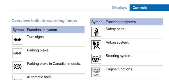
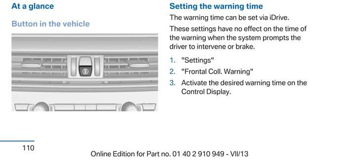
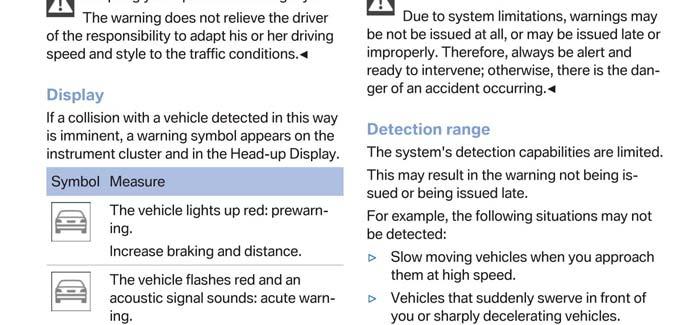
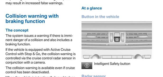
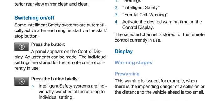
12 FORWARD COLLISION WARNING DATA SHEET 4: FORWARD COLLISION WARNING SYSTEM OPERATION (Page 1 of 3) 2014 BMW X5 How is the Forward Collision Warning presented X Warning light to the driver? (Check all that apply) X Buzzer or audible alarm Vibration Other Describe the method by which the driver is alerted. For example, if the warning is a light, where is it located, its color, size, words or symbol, does it flash on and off, etc. If it is a sound, describe if it is constant beep or a repeated beep. If it is a vibration, describe where it is felt (e.g., pedals, steering wheel), the dominant frequency (and possibly magnitude).the type of warning (light, audible, vibration, or combination) etc. The visual alert is provided to the driver in the two following phases: Prewarning: Symbol flashes once Acute Warning: Symbol flashes on / off The visual alert is displayed both in the center of the dashboard and also via the heads up display and is an image of the rear view of a car. The audible alert consists of a series of repeated beeps whose primary frequency is approximately 1999 Hz. 8
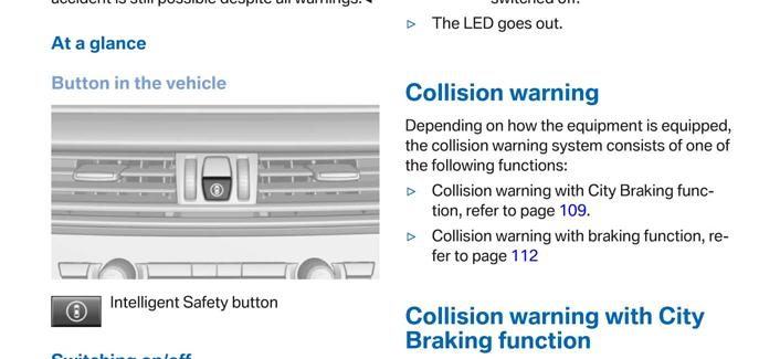
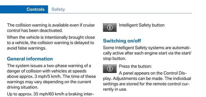
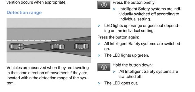
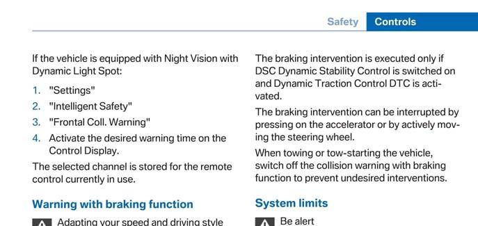
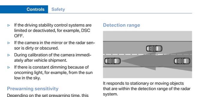
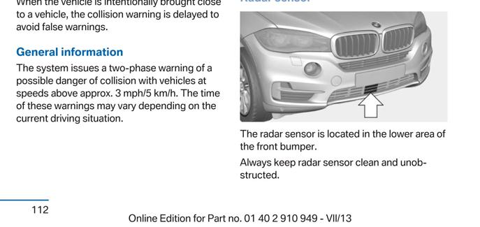
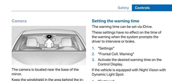
13 FORWARD COLLISION WARNING DATA SHEET 4: FORWARD COLLISION WARNING SYSTEM OPERATION (Page 2 of 3) 2014 BMW X5 Is the vehicle equipped with a switch whose purpose is to render FCW inoperable? X Yes No If yes please provide a full description including the switch location and method of operation, any associated instrument panel indicator, etc. A switch located in the middle of the center console underneath the switch for hazard lights allows the system to be turned off. The switch has a picture of a vehicle as seen from above surrounded by a illuminated green light. Pressing the switch once brings up the "Intelligent Safety" menu. Once in the "Intelligent Safety" menu, the user can select "Frontal Collision Warning" and toggle the system between "On" and "Individual" by pressing the switch once. The user can turn the system completely "Off" by pressing and holding the switch for a few seconds. Are there other driving modes or conditions that render FCW inoperable or reduce its effectiveness? If yes please provide a full description X Yes No Functional limitations: - Heavy fog, rain, sprayed water, snowfall - Tight curves - If the camera in the mirror or the radar sensor is dirty or obscured - During the calibration process of the camera immediately after vehicle shipment 9
14 FORWARD COLLISION WARNING DATA SHEET 4: FORWARD COLLISION WARNING SYSTEM OPERATION (Page 3 of 3) 2014 BMW X5 Is the vehicle equipped with a control whose purpose is to adjust the range setting or otherwise influence the operation of FCW? X Yes No If yes please provide a full description. Using the main controls for the infotainment center, the user can adjust the range of the FCW system through the following steps: Main Menu --> Settings --> Frontal Coll. Warning. Once in the Frontal Coll. Warning menu the system can be toggled between "Early", "Medium", and "Late" warning time modes. Notes: The vehicle required approximately 220 miles of driving over the road in order for the FCW system to function as intended. 10
15 Section III TEST PROCEDURES A. Test Procedure Overview Three test procedures were used, as follows: Test 1. Test 2. Test 3. Subject Vehicle (SV) Encounters Stopped Principal Other Vehicle (POV) on a Straight Road Subject Vehicle Encounters Decelerating Principal Other Vehicle Subject Vehicle Encounters Slower Principal Other Vehicle With the exception of trials associated with Test 1, all trials were performed with SV and POV automatic transmissions in Drive or with manual transmissions in the highest gear capable of sustaining the desired test speed. Manual transmission clutches remained engaged during all maneuvers. Except for Test 2, the brake lights of the POV were not illuminated. In order to pass the test, if the FCW system provides a warning timing adjustment for the driver, at least one setting must meet the criterion of the test procedure. Therefore, if the vehicle was equipped with a warning timing adjustment, only the most conservative (earliest warning) setting was tested. An overview of each of the test procedures follows. 1. TEST 1 - SUBJECT VEHICLE ENCOUNTERS STOPPED PRINCIPAL OTHER VEHICLE ON A STRAIGHT ROAD This test evaluates the ability of the FCW function to detect a stopped lead vehicle, as depicted in Figure 1. Figure 1. Depiction of Test 1 11
16 a. Alert Criteria In order to pass the test, the FCW alert must be issued when the time-tocollision (TTC) is at least 2.1 seconds. (Note: TTC values were computed in accordance with Ref 1). The TTC for this test was calculated by considering the speeds of the subject vehicle (SV) and the lead vehicle (POV) at the time of the FCW alert (i.e., when the SV and POV speeds are nominally equal to 45 and 0 mph (72.4 and 0 kph), respectively). b. Procedure The POV was parked in the center of a travel lane, with its longitudinal axis oriented parallel to the roadway edge, and facing the same direction as the SV, so the SV approaches the rear of the POV. The SV was driven at a nominal speed of 45 mph (72.4 kph) in the center of the lane of travel, toward the parked POV. The test began when the SV was 492 ft (150 m) from the POV and ended when either of the following occurred: The required FCW alert occurred. The TTC to the POV fell to less than 90 percent of the minimum allowable range (i.e., TTC = 1.9 sec) for the onset of the required FCW alert. The SV driver then steered and/or braked to keep the SV from striking the POV. For an individual test trial to be valid, the following was required throughout the test: The SV vehicle speed could not deviate from the nominal speed by more than 1.0 mph (1.6 kph) for a period of three seconds prior to (1) the required FCW alert or (2) before the range fell to less than 90 percent of the minimum allowable range for onset of the required FCW alert. The SV driver could not apply any force to the brake pedal before the required FCW alert occurred, or before the range fell to less than 90 percent of the minimum allowable range for onset of the required FCW alert. 12

17 The lateral distance between the centerline of the SV, relative to the centerline of the POV, in road coordinates, could not exceed 2.0 ft (0.6 m). The yaw rate of the SV could not exceed ±1 deg/sec during the test. Nominally, the Test 1 series was comprised of seven individual trials. The FCW system must satisfy the TTC alert criteria for at least five of the seven test trials. 2. TEST 2 SUBJECT VEHICLE ENCOUNTERS DECELERATING PRINCIPAL OTHER VEHICLE The SV in this test initially followed the POV at a constant time gap, and then the POV suddenly decelerated, as depicted in Figure 2. The test evaluates the ability of the FCW to recognize a decelerating lead vehicle and to issue an alert to SV driver in a timely manner. Figure 2. Depiction of Test 2 a. Alert Criteria In order to pass the test, the FCW alert must be issued when TTC is at least 2.4 seconds. The TTC for this test, a prediction of the time it would take for the SV to collide with the POV, was calculated by considering three factors at the time of the FCW alert: (1) the speed of the SV, (2) the speed of the POV, and (3) the deceleration of the POV 1. b. Procedure 1 To simplify calculation of the TTC for Test 2, the deceleration of the POV is assumed to remain constant from the time of the FCW alert until the POV comes to a stop (i.e., a constant rate of slowing is assumed). 13
18 Test 2 began with the SV and the POV traveling on a straight, flat road at a constant speed of 45.0 mph (72.4 kph), in the center of the lane of travel. The headway from the SV to the POV was nominally maintained at 98.4 ft (30 m) until the POV braking was initiated. The test began approximately 7 seconds before the driver of the POV started a braking maneuver in which the POV brakes were rapidly applied and modulated such that a constant deceleration of 0.3 g was achieved within 1.5 seconds after braking is initiated. The test ended when either of the following conditions was satisfied: The required FCW alert occurred. The TTC to the POV fell to less than 90% of the minimum allowable range (i.e., TTC = 2.2 sec) for the onset of the required FCW alert. The SV driver then steered and/or braked to keep the SV from striking the POV. For an individual test trial to be valid, the following was required throughout the test: The initial POV vehicle speed could not deviate from the nominal speed by more than 1.0 mph (1.6 kph) for a period of 3 seconds prior to the initiation of POV braking. The speed of the SV could not deviate from the nominal speed by more than 1.0 mph (1.6 kph) for a period of 3 seconds prior to (1) the required FCW alert or (2) before the range fell to less than 90 percent of the minimum allowable range for onset of the required FCW alert. The lateral distance between the centerline of the SV, relative to the centerline of the POV, in road coordinates, could not exceed 2.0 ft (0.6 m). The yaw rates of the SV and POV could not exceed ±1 deg/sec during the test. The POV deceleration level was nominally required to be 0.3 g within 1.5 seconds after initiation of POV braking. The acceptable error magnitude of the POV deceleration was ±0.03g, measured at the time the FCW alert first occurred. An 14
19 initial overshoot beyond the deceleration target was acceptable, however the first local deceleration peak observed during an individual trial could not exceed g for more than 50 ms. Additionally, the deceleration could not exceed 0.33 g over a period defined from (1) 500 ms after the first local deceleration peak occurs, to (2) the time when the FCW alert first occurred. The tolerance for the headway from the SV to the POV was ±8.2 ft (±2.5 m), measured at two instants in time: (1) three seconds prior to the time the POV brake application was initiated, and (2) at the time the POV brake application was initiated. SV driver could not apply any force to the brake pedal before the required FCW alert occurred, or before the range fell to less than 90 percent of the minimum allowable range for onset of the required FCW alert. Nominally, the Test 2 series was comprised of seven individual trials. The FCW system must satisfy the TTC alert criteria for at least five of the seven test trials. 3. TEST 3 SUBJECT VEHICLE ENCOUNTERS SLOWER PRINCIPAL OTHER VEHICLE This test examines the ability of the FCW system to recognize a slower lead vehicle being driven with a constant speed and issue a timely alert. As depicted in Figure 3, the scenario was conducted with a closing speed equal to 25.0 mph (40.2 kph). Figure 3. Depiction of Test 3 a. Alert Criteria 15
20 In order to pass the test, the FCW alert must be issued when TTC is at least 2.0 seconds. The TTC for this test, a prediction of the time it would take for the SV to collide with the POV, was calculated by considering the speeds of the SV and POV at the time of the FCW alert. b. Procedure Throughout the test, the POV was driven at a constant 20.0 mph (32.2 kph) in the center of the lane of travel. The SV was driven at 45.0 mph (72.4 kph), in the center lane of travel, toward the slow-moving POV. The test began when the headway from the SV to the POV was 329 ft (100 m) and ended when either of the following occurred: The required FCW alert occurred. The TTC to the POV fell to less than 90% of the minimum allowable range (i.e., TTC = 1.8 sec) for the onset of the required FCW alert. The SV driver then steered and/or braked to keep the SV from striking the POV. For an individual test trial to be valid, the following was required throughout the test: The SV vehicle speed could not deviate from the nominal speed by more than 1.0 mph (1.6 kph) for a period of 3 seconds prior to (1) the required FCW alert or (2) before the range fell to less than 90 percent of the minimum allowable range for onset of the required FCW alert. Speed of the POV could not deviate from the nominal speed by more than 1.0 mph (1.6 kph) during the test. The lateral distance between the centerline of the SV, relative to the centerline of the POV, in road coordinates, could not exceed 2.0 ft (0.6 m). The yaw rates of the SV and POV could not exceed ±1 deg/sec during the test. 16
21 SV driver could not apply any force to the brake pedal before the required FCW alert occurred, or before the range fell to less than 90 percent of the minimum allowable range for onset of the required FCW alert. Nominally, the Test 3 series was comprised of seven individual trials. The FCW system must satisfy the TTC alert criteria for at least five of the seven test trials. B. Principal Other Vehicle The vehicle used as the Principal Other Vehicle (POV) was a 2000 Honda Accord. This satisfied the test requirement of Ref 1 that the POV be a mid-size sedan. The vehicle had a rear license plate in order to provide a suitable representative radar profile. Vehicle loading consisted of the driver plus equipment and instrumentation. C. Automatic Braking System The POV was equipped with an automatic braking system, which was used in Test 2. The braking system consisted of the following components: High pressure nitrogen bottle, strapped to the front passenger seat, with regulator and pressure gauges. Pneumatic piston-type actuator, with solenoid valve Pickle switch to activate brakes D. Instrumentation Table 1 lists the sensors, signal conditioning and data acquisition equipment used for these tests. As part of the pre-test instrumentation verification process, the tonal frequency of the audible warning was determined through use of the PSD (Power Spectral Density) function in Matlab. This was accomplished in order to identify the center frequency around which a band-pass filter was applied to subsequent audible warning data such that the beginning of the audible warning could be programmatically determined. The band-pass filter used for the audible warning signal was a phase-less, forward-reverse pass, 5 th order elliptical (Cauer) digital filter, with 3 db peak-to-peak ripple, minimum stop-band attenuation of 60 db, and a pass-band of center frequency +/- 5% of the identified center frequency. 17
22 TABLE 1. TEST INSTRUMENTATION AND EQUIPMENT Tire Pressure Gauge Type Output Range Platform Scales Differential Global Positioning System Multi-Axis Inertial Sensing System Real-Time Calculation of Position and Velocity Relative to Lane Markings (LDW) and POV (FCW) Vehicle Tire Pressure Vehicle Total, Wheel, and Axle Load Position, Velocity Position; Longitudinal, Lateral, and Vertical Accels; Lateral, Longitudinal and Vertical Velocities; Roll, Pitch, Yaw Rates; Roll, Pitch, Yaw Angles Distance and Velocity to lane markings (LDW) and POV (FCW) psi kpa 8000 lb 35.6 kn Latitude: ±90 deg Longitude: ±180 deg Altitude: 0-18 km Velocity: knots Latitude: ±90 deg Longitude: ±180 deg Altitude: 0-18 km Velocity: knots Accel: ±100 m/s 2 Angular Rate: ±100 deg/s Angular Disp: ±180 deg Lateral Lane Dist: ±30 m Lateral Lane Velocity: ±20 m/sec Longitudinal Range to POV: ±200 m Longitudinal Range Rate: ±50 m/sec Accuracy, Other Primary Specs 0.5 psi 3.45 kpa ±1.0% of applied load Horizontal Position: ±1 cm Vertical Position: ±2 cm Velocity: 0.05 km/h Position: ±2 cm Velocity: 0.05 km/h Accel: 0.01% of full range Angular Rate: 0.01% of full range Roll/Pitch Angle: ±0.03 deg Heading Angle: ±0.1 deg Lateral Distance to Lane Marking: ±2 cm Lateral Velocity to Lane Marking: ±0.02m/sec Longitudinal Range: ±3 cm Longitudinal Range Rate: ±0.02 m/sec Ashcroft, D1005PS Mfr, Model Intercomp, SWII Trimble GPS Receiver, 5700 (base station and in-vehicle) Oxford Technical Solutions (OXTS), Inertial+ Oxford Technical Solutions (OXTS), RT-Range Serial Number NT NA NA Calibration Dates Last Due 1/23/2013 1/23/2014 1/30/2013 1/30/2014 2/8/2012 2/8/2014 2/7/2012 2/
23 Type Output Range Data Acquisition System [Includes amplification, antialiasing, and analog to digital conversion.] Microphone Light Sensor Accelerometer Coordinate Measurement Machine Record Time; Position; Velocity; Distance to lane markings; Headway distance; Closing Velocity; Lateral, Longitudinal, and Vertical Accels; Roll, Yaw, and Pitch Rates; Roll, Yaw and Pitch Angles. Sound (to measure time at alert) Light intensity (to measure time at alert) Acceleration (to measure time at alert) Inertial Sensing System Coordinates Sufficient to meet or exceed individual sensors Max SPL: 139 db/spl Frequency Response: 40 Hz 20 khz Spectral Bandwidth: nm Accuracy, Other Primary Specs Sound digitized at 10 khz, all other channels digitized at 100 Hz. Accuracy is sufficient to meet or exceed individual sensors 3 db over Freq. Resp. Range Rise time < 10 msec ±5g 3% of full range 0-8 ft m ±.0020 in. ±.051 mm (Single point articulation accuracy) Mfr, Model SoMat, edaq ECPU processor SoMat, High level Board EHLS Sennheiser, e614 DRI designed and developed Light Sensor Silicon Designs, Faro Arm, Fusion Serial Number MSHLB MSHLS NA NA NA UO Calibration Dates Last Due 4/24/13 4/24/14 NA NA NA 1/4/2013 1/4/
24 APPENDIX A Photographs A-1
25 LIST OF FIGURES Page Figure A1. Front View of Subject Vehicle. A-3 Figure A2. Rear View of Subject Vehicle.. A-4 Figure A3. Window Sticker (Monroney Label)... A-5 Figure A4. Vehicle Certification Label... A-6 Figure A5. Front View of Principal Other Vehicle... A-7 Figure A6. Rear View of Principal Other Vehicle... A-8 Figure A7. DGPS and Inertial Measurement Unit Installed in Subject Vehicle... A-9 Figure A8. Data Acquisition System Installed in Subject Vehicle... A-10 Figure A9. Computer Installed in Subject Vehicle... A-11 Figure A10. Brake Actuation System Installed in Principal Other Vehicle... A-12 Figure A11. Sensors for Detecting Visual and Audible Alerts... A-13 Figure A12. Visual Warning Display... A-14 Figure A13. Intelligent Safety Button, FCW On/Off... A-15 Figure A14 Menus for Adjusting FCW Settings... A-16 Figure A15 Menus for Adjusting FCW Settings... A-17 A-2

26 Figure A1. Front View of Subject Vehicle A-3

27 Figure A2. Rear View of Subject Vehicle A-4

28 Figure A3. Window Sticker (Monroney Label) A-5

29 Figure A4. Vehicle Certification Label A-6

30 Figure A5. Front View of Principal Other Vehicle A-7

31 Figure A6. Rear View of Principal Other Vehicle A-8

32 Figure A7. DGPS and Inertial Measurement Unit Installed in Subject Vehicle A-9

33 Figure A8. Data Acquisition System Installed in Subject Vehicle A-10

34 Figure A9. Computer Installed in Subject Vehicle A-11

35 Figure A10. Brake Actuation System Installed in Principal Other Vehicle A-12

36 Figure A11. Sensors for Detecting Visual and Audible Alerts A-13

37 Figure A12. Visual Warning Display A-14

38 Figure A13. Intelligent Safety Button, FCW On/Off A-15
39 Figure A14. Menus for Adjusting FCW Settings A-16
40 Figure A15. Menus for Adjusting FCW Settings A-17
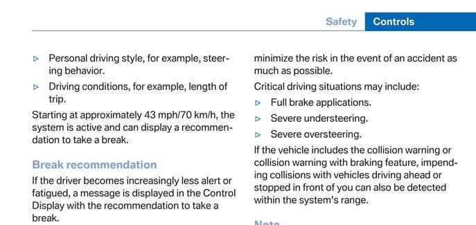
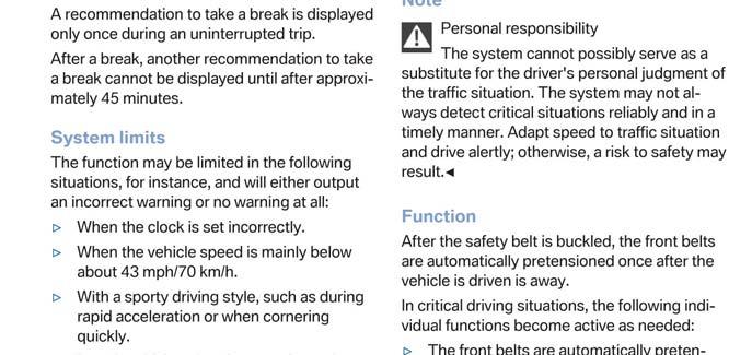
41 APPENDIX B Excerpts from Owner s Manual B-1
42 B-2
43 B-3
44 B-4
45 B-5
46 B-6
47 B-7
48 B-8
49 APPENDIX C Run Log C-1
50 Subject Vehicle: 2014 BMW X5 Date: 10 December 2013 Principal Other Vehicle: 2000 Honda Accord Run Test Type Valid Run? TTCW Sound (sec) TTCW Light (sec) TTCW Margin (sec) Pass/Fail Notes 1 FCW1 (Stopped) Y Pass 2 Y Pass 3 Y Pass 4 Y Pass 5 N yaw rate high 6 Y Pass 7 Y Pass 8 Y Pass 9 Y Pass 10 Y Pass 11 FCW3(Slower) N POV speed low 12 N lateral offset 13 Y Pass 14 Y Pass 15 Y Pass 16 Y Pass 17 Y Pass 18 N C-2
51 Subject Vehicle: 2014 BMW X5 Date: 10 December 2013 Principal Other Vehicle: 2000 Honda Accord Run Test Type Valid Run? TTCW Sound (sec) TTCW Light (sec) TTCW Margin (sec) Pass/Fail Notes 19 FCW3(Slower) N POV yaw rate 20 Y Pass 21 Y Pass 22 FCW2 (Braking) Y Pass 23 Y Pass 24 Y Pass 25 N SV speed high 26 Y Pass 27 Y Pass 28 Y Pass 29 Y Pass C-3
52 APPENDIX D Time History Plots D-1
53 LIST OF FIGURES Page Figure D1. Example Time History for Test Type 1, Passing... D-7 Figure D2. Example Time History for Test Type 2, Failing... D-8 Figure D3. Example Time History for Test Type 2, Passing... D-9 Figure D4. Example Time History for Test Type 3, Failing... D-10 Figure D5. Example Time History for Test Type 3, Passing... D-11 Figure D6. Example Time History for Test Type 2, Invalid Run Due to Subject Vehicle Yaw Rate... D-12 Figure D7. Time History for Run 1, FCW Test 1, Audible Warning... D-13 Figure D8. Time History for Run 1, FCW Test 1, Visual Warning... D-14 Figure D9. Time History for Run 2, FCW Test 1, Audible Warning... D-15 Figure D10. Time History for Run 2, FCW Test 1, Visual Warning... D-16 Figure D11. Time History for Run 3, FCW Test 1, Audible Warning... D-17 Figure D12. Time History for Run 3, FCW Test 1, Visual Warning... D-18 Figure D13. Time History for Run 4, FCW Test 1, Audible Warning... D-19 Figure D14. Time History for Run 4, FCW Test 1, Visual Warning... D-20 Figure D15. Time History for Run 6, FCW Test 1, Audible Warning... D-21 Figure D16. Time History for Run 6, FCW Test 1, Visual Warning... D-22 Figure D17. Time History for Run 7, FCW Test 1, Audible Warning... D-23 Figure D18. Time History for Run 7, FCW Test 1, Visual Warning... D-24 Figure D19. Time History for Run 8, FCW Test 1, Audible Warning... D-25 Figure D20. Time History for Run 8, FCW Test 1, Visual Warning... D-26 Figure D21. Time History for Run 9, FCW Test 1, Audible Warning... D-27 Figure D22. Time History for Run 9, FCW Test 1, Visual Warning... D-28 Figure D23. Time History for Run 10, FCW Test 1, Audible Warning... D-29 Figure D24. Time History for Run 10, FCW Test 1, Visual Warning... D-30 Figure D25. Time History for Run 22, FCW Test 2, Audible Warning... D-31 Figure D26. Time History for Run 22, FCW Test 2, Visual Warning... D-32 Figure D27. Time History for Run 23, FCW Test 2, Audible Warning... D-33 Figure D28. Time History for Run 23, FCW Test 2, Visual Warning... D-34 D-2
54 Figure D29. Time History for Run 24, FCW Test 2, Audible Warning... D-35 Figure D30. Time History for Run 24, FCW Test 2, Visual Warning... D-36 Figure D31. Time History for Run 26, FCW Test 2, Audible Warning... D-37 Figure D32. Time History for Run 26, FCW Test 2, Visual Warning... D-38 Figure D33. Time History for Run 27, FCW Test 2, Audible Warning... D-39 Figure D34. Time History for Run 27, FCW Test 2, Visual Warning... D-40 Figure D35. Time History for Run 28, FCW Test 2, Audible Warning... D-41 Figure D36. Time History for Run 28, FCW Test 2, Visual Warning... D-42 Figure D37. Time History for Run 29, FCW Test 2, Audible Warning... D-43 Figure D38. Time History for Run 29, FCW Test 2, Visual Warning... D-44 Figure D39. Time History for Run 13, FCW Test 3, Audible Warning... D-45 Figure D40. Time History for Run 13, FCW Test 3, Visual Warning... D-46 Figure D41. Time History for Run 14, FCW Test 3, Audible Warning... D-47 Figure D42. Time History for Run 14, FCW Test 3, Visual Warning... D-48 Figure D43. Time History for Run 15, FCW Test 3, Audible Warning... D-49 Figure D44. Time History for Run 15, FCW Test 3, Visual Warning... D-50 Figure D45. Time History for Run 16, FCW Test 3, Audible Warning... D-51 Figure D46. Time History for Run 16, FCW Test 3, Visual Warning... D-52 Figure D47. Time History for Run 17, FCW Test 3, Audible Warning... D-53 Figure D48. Time History for Run 17, FCW Test 3, Visual Warning... D-54 Figure D49. Time History for Run 20, FCW Test 3, Audible Warning... D-55 Figure D50. Time History for Run 20, FCW Test 3, Visual Warning... D-56 Figure D51. Time History for Run 21, FCW Test 3, Audible Warning... D-57 Figure D52. Time History for Run 21, FCW Test 3, Visual Warning... D-58 D-3
55 D-4 D. Description of Time History Plots A set of time history plots is provided for each valid run in the test series. Each set of plots comprises time varying data from both the Subject Vehicle and the Principal Other Vehicle, as well as pass/fail envelopes and thresholds. The following is a description of data types shown in the time history plots, as well as a description of the color code indicating to which vehicle the data pertain. Time History Plot Description Each time history plot consists of data pertinent to the test type under consideration. The data shown in time history plots for test type 2 differs slightly from the data shown in test types 1 and 3, owing to the headway distance criterion which is used exclusively for test type 2. Time history figures include the following sub-plots: Event indicates timing of warning issued by FCW system. Depending on the type of FCW alert or instrumentation used to measure the alert, this can be any of the following,: o Filtered and rectified sound signal o Filtered and rectified acceleration (e.g., steering wheel vibration) o Light sensor signal o Discrete on/off value TTC (sec) indicates the Time to Collision as calculated up to the point of FCW alert issuance. The value of TTCW (Time to Collision at Warning) is given numerically on the right side of the figure. A passing value is indicated in green, while a failing value is indicated in red. SV Speed (mph) speed of the Subject Vehicle POV Speed (mph) speed of the Principal Other Vehicle Yaw Rate (deg/sec) yaw rate of both the Subject Vehicle and Principal Other Vehicle Lateral Offset (ft) lateral offset within the lane from the Subject Vehicle to the Principal Other Vehicle Ax (g) Longitudinal acceleration of both the Subject Vehicle and Principal Other Vehicle Headway (ft) Longitudinal separation between front of Subject Vehicle to rear of Principal Other Vehicle (Exclusive to test type 2)
56 D-5 Envelopes and Thresholds Each of the time history plot figures can contain either green or yellow envelopes and/or black threshold lines. These envelopes and thresholds are used to programmatically and visually determine the validity of a given test run. Envelope and threshold exceedances are indicated with either red shading or red asterisks, and red text is placed to the right side of the plot indicating the type of exceedance. Green envelopes indicate that the time-varying data should not exceed the envelope boundaries at any time within the envelope. Exceedances of a green envelope are indicated by red shading in the area between the measured time-varying data and the envelope boundaries. Yellow envelopes indicate that the time-varying data should not exceed the envelope only at the left and/or right ends. Exceedances at the left or right extent of a yellow envelope are indicated by red asterisks. For test type 2, the plot indicating the longitudinal acceleration of the Principal Other Vehicle includes a solid black threshold line indicating the maximum deceleration (-0.33 g) allowed while braking. Exceedance of this threshold is indicated with red shading in the area between the measured time-varying data and the threshold boundary. Color Codes Color codes have been adopted to easily identify which data correspond to which vehicle, as well as to indicate the types of envelopes and thresholds used in the plots. Color codes can be broken into four categories: 1. Time-varying data 2. Validation envelopes and thresholds 3. Instantaneous samplings 4. Text 1. Time-varying data color codes: Blue = Subject Vehicle data Magenta = Principal Other Vehicle data
57 D-6 Brown = Relative data between SV and POV (i.e., TTC, lateral offset and headway distance) 2. Validation envelope and threshold color codes: Green envelope = time varying data must be within the envelope at all times in order to be valid Yellow envelope = time varying data must be within limits at left and/or right ends Black threshold (Solid) = time varying data must not exceed this threshold in order to be valid Black threshold (Dashed) = for reference only this can include warning level thresholds, TTC thresholds, and acceleration thresholds 3. Instantaneous sampling color codes: Green circle = passing or valid value at a given moment in time Red asterisk = failing or invalid value at a given moment in time 4. Text color codes: Green = passing or valid value Red = failing or invalid value Examples of time history plots for each test type (including passing, failing and invalid runs) are shown in Figure D1 through Figure D6. Actual time history data plots for the vehicle under consideration are provided subsequently.
58 Figure D1. Example Time History for Test Type 1, Passing D-7
59 Figure D2. Example Time History for Test Type 2, Failing D-8

60 Figure D3. Example Time History for Test Type 2, Passing D-9
61 Figure D4. Example Time History for Test Type 3, Failing D-10

62 Figure D5. Example Time History for Test Type 3, Passing D-11

63 Figure D6. Example Time History for Test Type 2, Invalid Run Due to Subject Vehicle Yaw Rate D-12
64 Figure D7. Time History for Run 1, FCW Test 1, Audible Warning D-13
65 Figure D8. Time History for Run 1, FCW Test 1, Visual Warning D-14
66 Figure D9. Time History for Run 2, FCW Test 1, Audible Warning D-15
67 Figure D10. Time History for Run 2, FCW Test 1, Visual Warning D-16
68 Figure D11. Time History for Run 3, FCW Test 1, Audible Warning D-17
69 Figure D12. Time History for Run 3, FCW Test 1, Visual Warning D-18
70 Figure D13. Time History for Run 4, FCW Test 1, Audible Warning D-19
71 Figure D14. Time History for Run 4, FCW Test 1, Visual Warning D-20
72 Figure D15. Time History for Run 6, FCW Test 1, Audible Warning D-21
73 Figure D16. Time History for Run 6, FCW Test 1, Visual Warning D-22
74 Figure D17. Time History for Run 7, FCW Test 1, Audible Warning D-23
75 Figure D18. Time History for Run 7, FCW Test 1, Visual Warning D-24
76 Figure D19. Time History for Run 8, FCW Test 1, Audible Warning D-25
77 Figure D20. Time History for Run 8, FCW Test 1, Visual Warning D-26
78 Figure D21. Time History for Run 9, FCW Test 1, Audible Warning D-27
79 Figure D22. Time History for Run 9, FCW Test 1, Visual Warning D-28
80 Figure D23. Time History for Run 10, FCW Test 1, Audible Warning D-29
81 Figure D24. Time History for Run 10, FCW Test 1, Visual Warning D-30
82 Figure D25. Time History for Run 22, FCW Test 2, Audible Warning D-31
83 Figure D26. Time History for Run 22, FCW Test 2, Visual Warning D-32
84 Figure D27. Time History for Run 23, FCW Test 2, Audible Warning D-33
85 Figure D28. Time History for Run 23, FCW Test 2, Visual Warning D-34
86 Figure D29. Time History for Run 24, FCW Test 2, Audible Warning D-35
87 Figure D30. Time History for Run 24, FCW Test 2, Visual Warning D-36
88 Figure D31. Time History for Run 26, FCW Test 2, Audible Warning D-37
89 Figure D32. Time History for Run 26, FCW Test 2, Visual Warning D-38
90 Figure D33. Time History for Run 27, FCW Test 2, Audible Warning D-39
91 Figure D34. Time History for Run 27, FCW Test 2, Visual Warning D-40
92 Figure D35. Time History for Run 28, FCW Test 2, Audible Warning D-41
93 Figure D36. Time History for Run 28, FCW Test 2, Visual Warning D-42
94 Figure D37. Time History for Run 29, FCW Test 2, Audible Warning D-43
95 Figure D38. Time History for Run 29, FCW Test 2, Visual Warning D-44
96 Figure D39. Time History for Run 13, FCW Test 3, Audible Warning D-45
97 Figure D40. Time History for Run 13, FCW Test 3, Visual Warning D-46
98 Figure D41. Time History for Run 14, FCW Test 3, Audible Warning D-47
99 Figure D42. Time History for Run 14, FCW Test 3, Visual Warning D-48
100 Figure D43. Time History for Run 15, FCW Test 3, Audible Warning D-49
101 Figure D44. Time History for Run 15, FCW Test 3, Visual Warning D-50
102 Figure D45. Time History for Run 16, FCW Test 3, Audible Warning D-51
103 Figure D46. Time History for Run 16, FCW Test 3, Visual Warning D-52
104 Figure D47. Time History for Run 17, FCW Test 3, Audible Warning D-53
105 Figure D48. Time History for Run 17, FCW Test 3, Visual Warning D-54
106 Figure D49. Time History for Run 20, FCW Test 3, Audible Warning D-55
107 Figure D50. Time History for Run 20, FCW Test 3, Visual Warning D-56
108 Figure D51. Time History for Run 21, FCW Test 3, Audible Warning D-57
109 Figure D52. Time History for Run 21, FCW Test 3, Visual Warning D-58
DYNAMIC RESEARCH, INC. 355 Van Ness Avenue, STE 200 Torrance, California 90501
 OCAS-DRI-FCW-13-001 NCAP FORWARD COLLISION WARNING CONFIRMATION TEST 2013 Cadillac XTS DYNAMIC RESEARCH, INC. 355 Van Ness Avenue, STE 200 Torrance, California 90501 4 October 2012 Final Report Prepared
Rollover Warning/Control for Sports Utility Vehicles
 Rollover Warning/Control for Sports Utility Vehicles Bo-Chiuan Chen, GSRA Huei Peng, Associate Prof. Dept. of Mechanical Engineering and Applied Mechanics University of Michigan 1 Outline Introduction
SUBPART C - STRUCTURE
 SUBPART C - STRUCTURE GENERAL CS 23.301 Loads (a) Strength requirements are specified in terms of limit loads (the maximum loads to be expected in service) and ultimate loads (limit loads multiplied by
DOT HS September Crash Factors in Intersection-Related Crashes: An On-Scene Perspective
 DOT HS 811 366 September 2010 Crash Factors in Intersection-Related Crashes: An On-Scene Perspective DISCLAIMER This publication is distributed by the U.S. Department of Transportation, National Highway
OBSERVATION OF GAP ACCEPTANCE DURING INTERSECTION APPROACH
 OBSERVATION OF GAP ACCEPTANCE DURING INTERSECTION APPROACH Delphine Cody, Christopher Nowakowski, Bénédicte Bougler California PATH program - Institute of Transportation Studies University of California,
Proposal for amendments to Regulation No. 79 to include ACSF > 10 km/h
 Informal Document ACSF-02-03 Submitted by the expert from Germany Proposal for amendments to Regulation No. 79 to include ACSF > 10 km/h The modifications to the Regulation are marked in blue bold and
Fire Apparatus Operator Aircraft Rescue and Fire Fighting
 Fire Apparatus Operator Aircraft Rescue and Fire Fighting Skill Sheet Package Based on NFPA 1002: Standard on Fire Apparatus Driver/ Operator Professional Qualifications, 2014 Edition. Alabama Fire College
Developed by: The American Traffic Safety Services Association (ATSSA) 15 Riverside Parkway, Suite 100 Fredericksburg, VA
 15 Riverside Parkway, Suite 100 Fredericksburg, VA") Addendum Developed by: The American Traffic Safety Services Association (ATSSA) 15 Riverside Parkway, Suite 100 Fredericksburg, VA 22406-1022 800-272-8772 This material is based upon work supported by
Addendum Developed by: The American Traffic Safety Services Association (ATSSA) 15 Riverside Parkway, Suite 100 Fredericksburg, VA 22406-1022 800-272-8772 This material is based upon work supported by
CHAPTER 1 STANDARD PRACTICES
 CHAPTER 1 STANDARD PRACTICES OBJECTIVES 1) Functions and Limitations 2) Standardization of Application 3) Materials 4) Colors 5) Widths and Patterns of Longitudinal Pavement Marking Lines 6) General Principles
Collision Avoidance based on Camera and Radar Fusion. Jitendra Shah interactive Summer School 4-6 July, 2012
 Collision Avoidance based on Camera and Radar Fusion Jitendra Shah interactive Summer School 4-6 July, 2012 Agenda Motivation Perception requirements for collision avoidance Situation classification and
Emergency Vehicle Driver
 Emergency Vehicle Driver Skill Sheet Package Based on NFPA 1002: Standard on Fire Apparatus Driver/Operator Professional Qualifications, 2014 Edition. Alabama Fire College February 2016 0 /09/2017 Alabama
MOBILEYE SHIELD + COLLISION AVOIDANCE SYSTEM OUR VISION. YOUR SAFETY.
 MOBILEYE SHIELD + COLLISION AVOIDANCE SYSTEM OUR VISION. YOUR SAFETY. MOBILEYE SHIELD + OUR SOLUTION FOR PEDESTRIAN & CYCLIST SAFETY The Mobileye Shield+ System is the latest technological advancement
Fire Apparatus Operator: ARFF
 Fire Apparatus Operator: ARFF Skill Sheet Package Based on NFPA 1002: Standard on Fire Apparatus Driver/ Operator Professional Qualifications, 2017 Edition. Alabama Fire College November 26, 2018 Alabama
Real-Time Smoothness Measurements on Concrete Pavements During Construction
 Recommended Practice for Real-Time Smoothness Measurements on Concrete Pavements During Construction XX-## (2017) 1. SCOPE 1.1. This document provides language that can be used by an Owner-Agency to develop
OBJECTIFICATION TECHNOLOGY OF PERCEIVED SAFETY & COMFORT DURING ASSISTED DRIVING
 OBJECTIFICATION TECHNOLOGY OF PERCEIVED SAFETY & COMFORT DURING ASSISTED DRIVING Erich Ramschak Dr. Jürgen Holzinger Erik Bogner AVL List GmbH erich.ramschak@avl.com ConCar-Forum Berlin 5.-6.July 2017
Proposal for amendments to Regulation No. 79 to include ACSF > 10 km/h
 Submitted by France Informal Document: ACSF-04-03 Proposal based on ACSF-03-16 Proposal for amendments to Regulation No. 79 to include ACSF > 10 km/h The modifications to the Regulation are marked in bold
RESOLUTION MSC.94(72) (adopted on 22 May 2000) PERFORMANCE STANDARDS FOR NIGHT VISION EQUIPMENT FOR HIGH-SPEED CRAFT (HSC)
 (adopted on 22 May 2000) PERFORMANCE STANDARDS FOR NIGHT VISION EQUIPMENT FOR HIGH-SPEED CRAFT (HSC)") MSC 72/23/Add.1 RESOLUTION MSC.94(72) EQUIPMENT FOR HIGH-SPEED CRAFT (HSC) THE MARITIME SAFETY COMMITTEE, RECALLING Article 28(b) of the Convention on the International Maritime Organization concerning
MSC 72/23/Add.1 RESOLUTION MSC.94(72) EQUIPMENT FOR HIGH-SPEED CRAFT (HSC) THE MARITIME SAFETY COMMITTEE, RECALLING Article 28(b) of the Convention on the International Maritime Organization concerning
JAR-23 Normal, Utility, Aerobatic, and Commuter Category Aeroplanes \ Issued 11 March 1994 \ Section 1- Requirements \ Subpart C - Structure \ General
 JAR 23.301 Loads \ JAR 23.301 Loads (a) Strength requirements are specified in terms of limit loads (the maximum loads to be expected in service) and ultimate loads (limit loads multiplied by prescribed
Exemplary Conditional Automation (Level 3) Use Case Description Submitted by the Experts of OICA as input to the IWG ITS/AD
 Use Case Description Submitted by the Experts of OICA as input to the IWG ITS/AD") Submitted by OICA Document No. ITS/AD-06-05 (6th ITS/AD, 3 November 2015, agenda item 3-2) Exemplary Conditional Automation (Level 3) Use Case Description Submitted by the Experts of OICA as input to the
Submitted by OICA Document No. ITS/AD-06-05 (6th ITS/AD, 3 November 2015, agenda item 3-2) Exemplary Conditional Automation (Level 3) Use Case Description Submitted by the Experts of OICA as input to the
Colorado Division of Fire Prevention & Control Driver Operator JPRs (NFPA 1002, 2014 Edition)
") Colorado Division of Fire Prevention & Control Driver Operator JPRs ( Edition) JPR # Task Initial Certification JPR Requirement: 8 Mandatory Renewal JPR Requirement: 100% of All JPRs (including all subsections)
Colorado Division of Fire Prevention & Control Driver Operator JPRs ( Edition) JPR # Task Initial Certification JPR Requirement: 8 Mandatory Renewal JPR Requirement: 100% of All JPRs (including all subsections)
Texas Driver Education Classroom and In-car Instruction Model Curriculum
 Texas Driver Education Classroom and In-car Instruction Model Curriculum BasicManeuvering Tasks: Moderate Risk Environment Module Four SPACE MANAGEMENT CONCEPTS CHANGING LANES TURNABOUTS PARKING WORKSHEETS
Evaluation of the Wisconsin DOT Walking Profiler
 Final Report Evaluation of the Wisconsin DOT Walking Profiler March 2007 U.S. Department of Transportation Federal Highway Administration Notice This document is disseminated under the sponsorship of the
EUROPEAN NEW CAR ASSESSMENT PROGRAMME (Euro NCAP) SLED TEST PROCEDURE FOR ASSESSING KNEE IMPACT AREAS
 SLED TEST PROCEDURE FOR ASSESSING KNEE IMPACT AREAS") www.euroncap.com EUROPEAN NEW CAR ASSESSMENT PROGRAMME (Euro NCAP) SLED TEST PROCEDURE FOR ASSESSING KNEE IMPACT AREAS Version 1.0a December 2004 Sled Test Procedure for Assessing Knee Impact Areas (V1.0a)
www.euroncap.com EUROPEAN NEW CAR ASSESSMENT PROGRAMME (Euro NCAP) SLED TEST PROCEDURE FOR ASSESSING KNEE IMPACT AREAS Version 1.0a December 2004 Sled Test Procedure for Assessing Knee Impact Areas (V1.0a)
Fire Apparatus Operator: Pumper
 Fire Apparatus Operator: Pumper Skill Sheet Package Based on NFPA 1002: Standard on Fire Apparatus Driver/Operator Professional Qualifications, 2014 Edition. Alabama Fire College February 2016 revised
Grover 1 EMERGENCY LANE KEEPING (ELK) SYSTEM TEST DEVELOPMENT. Colin, Grover Matthew, Avery Thatcham Research UK. Paper Number ABSTRACT
 SYSTEM TEST DEVELOPMENT. Colin, Grover Matthew, Avery Thatcham Research UK. Paper Number ABSTRACT") EMERGENCY LANE KEEPING (ELK) SYSTEM TEST DEVELOPMENT Colin, Grover Matthew, Avery Thatcham Research UK Paper Number 17-0289 ABSTRACT LDW and LKA systems are becoming more prevalent on modern vehicles,
EMERGENCY LANE KEEPING (ELK) SYSTEM TEST DEVELOPMENT Colin, Grover Matthew, Avery Thatcham Research UK Paper Number 17-0289 ABSTRACT LDW and LKA systems are becoming more prevalent on modern vehicles,
Chapter Twenty-eight SIGHT DISTANCE BUREAU OF LOCAL ROADS AND STREETS MANUAL
 Chapter Twenty-eight SIGHT DISTANCE BUREAU OF LOCAL ROADS AND STREETS MANUAL Jan 2006 SIGHT DISTANCE 28(i) Chapter Twenty-eight SIGHT DISTANCE Table of Contents Section Page 28-1 STOPPING SIGHT DISTANCE
AN31E Application Note
 Balancing Theory Aim of balancing How an unbalance evolves An unbalance exists when the principle mass axis of a rotating body, the so-called axis of inertia, does not coincide with the rotational axis.
Evaluation of the ACC Vehicles in Mixed Traffic: Lane Change Effects and Sensitivity Analysis
 CALIFORNIA PATH PROGRAM INSTITUTE OF TRANSPORTATION STUDIES UNIVERSITY OF CALIFORNIA, BERKELEY Evaluation of the ACC Vehicles in Mixed Traffic: Lane Change Effects and Sensitivity Analysis Petros Ioannou,
EZ Boom 2010 System for the EZ Guide 500 Lightbar Triangle Ag Services Users Guide
 EZ Boom 2010 System for the EZ Guide 500 Lightbar Triangle Ag Services Users Guide Parts of the Controller (For details on the parts of the EZ Boom controller refer to Appendix F) Status Indicator Rate
THE EFFECTS OF LEAD-VEHICLE SIZE ON DRIVER FOLLOWING BEHAVIOR: IS IGNORANCE TRULY BLISS?
 THE EFFECTS OF LEAD-VEHICLE SIZE ON DRIVER FOLLOWING BEHAVIOR: IS IGNORANCE TRULY BLISS? James R. Sayer, Mary Lynn Mefford Human Factors Division University of Michigan Transportation Research Institute
Product Guide. Crawler Crane
 Crawler Crane 220 US Tons (100 Metric Tons) @ 16 ft 5 in Radius 285 ft Max Tip (Main Boom) Main Boom, Fixed Jib and Luffing Jib Configurations Product Guide KEY FEATURES ULTRA CAB The Ultra Cab, designed
7 th International Conference on Wind Turbine Noise Rotterdam 2 nd to 5 th May 2017
 7 th International Conference on Wind Turbine Noise Rotterdam 2 nd to 5 th May 2017 Sound power level measurements 3.0 ir. L.M. Eilders, Peutz bv: l.eilders@peutz.nl ing. E.H.A. de Beer, Peutz bv: e.debeer@peutz.nl
MOBILEYE SHIELD+ COLLISION AVOIDANCE SYSTEM
 MOBILEYE SHIELD+ COLLISION AVOIDANCE SYSTEM MOBILEYE SHIELD + OUR SOLUTION FOR PEDESTRIAN & CYCLIST SAFETY The Mobileye Shield+ System is the latest technological advancement for preventing collisions
On-Road Skills Demonstration
 TRAINING TOOL On-Road Skills Demonstration DRIVING THE FUTURE 2 ON-ROAD SKILLS DEMONSTRATION TRAINING TOOL On-Road Skills Demonstration This document is a resource for consistent and objective evaluation
State of Nevada Department of Transportation Materials Division
 State of Nevada Department of Transportation Materials Division METHOD OF TEST FOR EVALUATION OF PAVEMENT RIDE QUALITY USING INERTIAL PROFILING SYSTEMS SCOPE This test method describes the procedure used
APPENDIX A TWO-LANE RURAL ROADS ELEMENTS OF DESIGN CREST VERTICAL CURVES
 APPENDIX A TWO-LANE RURAL ROADS ELEMENTS OF DESIGN CREST VERTICAL CURVES 1. Two-lane Rural Roads 1.1 Introduction The definition of rural area can be derived from the definition of urban areas. Officially,
PEAPOD. Pneumatically Energized Auto-throttled Pump Operated for a Developmental Upperstage. Test Readiness Review
 PEAPOD Pneumatically Energized Auto-throttled Pump Operated for a Developmental Upperstage Test Readiness Review Customer: Special Aerospace Services Chris Webber and Tim Bulk 1 Overview Project Overview
BOTTOM MAPPING WITH EM1002 /EM300 /TOPAS Calibration of the Simrad EM300 and EM1002 Multibeam Echo Sounders in the Langryggene calibration area.
 BOTTOM MAPPING WITH EM1002 /EM300 /TOPAS Calibration of the Simrad EM300 and EM1002 Multibeam Echo Sounders in the Langryggene calibration area. by Igor Kazantsev Haflidi Haflidason Asgeir Steinsland Introduction
STATIC AND DYNAMIC EVALUATION OF THE DRIVER SPEED PERCEPTION AND SELECTION PROCESS
 STATIC AND DYNAMIC EVALUATION OF THE DRIVER SPEED PERCEPTION AND SELECTION PROCESS David S. Hurwitz, Michael A. Knodler, Jr. University of Massachusetts Amherst Department of Civil & Environmental Engineering
2015 State Roadeo Written Test
 2015 State Roadeo Written Test Name: District: PURPOSE OF TEST: The purpose of this test is to showcase the knowledge of the contestant and promote education of more in-depth knowledge which pertains to
New Safety Features for Crash Avoidance. Dr. Kay Stepper Robert Bosch LLC
 Casualty Acturial Society Spring Meeting New Safety Features for Crash Avoidance Dr. Kay Stepper Robert Bosch LLC Agenda Overview and Technology Milestones U.S. Accident Statistics & Consumer Interests
OPERATING INERTIAL PROFILERS AND EVALUATING PAVEMENT PROFILES
 Test Procedure for OPERATING INERTIAL PROFILERS AND EVALUATING PAVEMENT TxDOT Designation: Tex-1001-S Effective Date: January 2017 1. SCOPE 1.1 This test method: covers use of an inertial profiler for
ATT-66/96, DENSITY TEST, ASBC CONTROL STRIP METHOD
 1.0 Scope ATT-66/96, DENSITY TEST, ASBC CONTROL STRIP METHOD 1.0 SCOPE This test procedure describes the method of determining the required minimum number of "passes" with approved compaction equipment,
EUROPEAN NEW CAR ASSESSMENT PROGRAMME (Euro NCAP) SLED TEST PROCEDURE FOR ASSESSING KNEE IMPACT AREAS. For 2020 implementation
 SLED TEST PROCEDURE FOR ASSESSING KNEE IMPACT AREAS. For 2020 implementation") EUROPEAN NEW CAR ASSESSMENT PROGRAMME (Euro NCAP) SLED TEST PROCEDURE FOR ASSESSING KNEE IMPACT AREAS For 2020 implementation Copyright Euro NCAP 2018 - This work is the intellectual property of Euro NCAP.
EUROPEAN NEW CAR ASSESSMENT PROGRAMME (Euro NCAP) SLED TEST PROCEDURE FOR ASSESSING KNEE IMPACT AREAS For 2020 implementation Copyright Euro NCAP 2018 - This work is the intellectual property of Euro NCAP.
Qualification of Fastrak & First Gen Product to Railway applications Shock and Vibration Standard EN 61373
 Qualification of Fastrak & First Gen Product to Railway applications Shock and Vibration Standard EN 61373 (Governing Standard BS EN 5155 Railway Applications Electronic equipment used on rolling stock)
GUIDELINES FOR USING DECISION SIGHT DISTANCE AT IGNALIZED INTERSECTIONS NEAR VERTICAL CURVES
 1. Report No. FHWA/TX-05/0-4084-P2 4. Title and Subtitle 2. Government Accession No. 3. Recipient's Catalog No. GUIDELINES FOR USING DECISION SIGHT DISTANCE AT IGNALIZED INTERSECTIONS NEAR VERTICAL CURVES
AN EXPERIMENTAL INVESTIGATION OF SPILLING BREAKERS
 AN EXPERIMENTAL INVESTIGATION OF SPILLING BREAKERS Prof. James H. Duncan Department of Mechanical Engineering University of Maryland College Park, Maryland 20742-3035 phone: (301) 405-5260, fax: (301)
Development and Evaluations of Advanced Emergency Braking System Algorithm for the Commercial Vehicle
 Development and Evaluations of Advanced Emergency Braking System Algorithm for the Commercial Vehicle Taeyoung, Lee Kyongsu, Yi School of Mechanical and Aerospace Engineering, Seoul National University
Vermont Permit Test Flash Cards
 Vermont Permit Test Flash Cards Study online at quizlet.com/_aormb are the most likely places for car and motorcycle collisions to occur. intersections are areas around trucks where cars disappear 2. :
Pass your Driving Test with confidence
 Pass your Driving Test with confidence Sample theory questions, and answers to help you prepare for your driving test. Q1. When should you not drive? While under the influence of alcohol, drugs (prescribed
LECTUR 10 CHARACTERISTICS OF THE DRIVER, THE PEDESTRIAN, THE VEHICLE AND THE ROAD. One problem that faces traffic and transportation engineers is:
 LECTUR 10 CHARACTERISTICS OF THE DRIVER, THE PEDESTRIAN, THE VEHICLE AND THE ROAD 3.1 DRIVER CHARACTERISTICS Physiological Measurable and Usually Quantifiable Psychological Much more difficult to measure
Pneumatic high-pressure controller Model CPC7000
 Calibration technology Pneumatic high-pressure controller Model CPC7000 WIKA data sheet CT 27.63 Applications Healthcare and avionics industry Industry (laboratory, workshop and production) Transmitter
Dynamic Positioning Control Augmentation for Jack-up Vessels
 DYNAMIC POSITIONING CONFERENCE October 9-10, 2012 Design and Control Session Dynamic Positioning Control Augmentation for Jack-up Vessels By Bradley Deghuee L-3 Communications 1 Introduction Specialized
Calibration Summary of Test Report No.: Sample
 Calibration Summary of Test Report No.:30043 Rion Type: NL52/EX Serial no: 00732122 Customer: Scantek, Inc. Address: 6430 Dobbin Rd., Suite C, Columbia MD, 21045 Contact Person: Mariana Buzduga Phone No.:
BHATNAGAR. Reducing Delay in V2V-AEB System by Optimizing Messages in the System
 Reducing Delay in V2V-AEB System by Optimizing Messages in the System Shalabh Bhatanagar Stanley Chien Yaobin Chen TASI, IUPUI, Indianapolis USA Paper Number: 17-0330 ABSTRACT In V2V-AEB (Vehicle to Vehicle
Identify the letter of the choice that best completes the statement or answers the question.
 Chapter 04 - Practice Questions Multiple Choice Identify the letter of the choice that best completes the statement or answers the question. 1) Basic tools for low-risk driving might be a. good tires and
GUIDELINES FOR EMERGENCY TRAFFIC CONTROL
 GUIDELINES FOR EMERGENCY TRAFFIC CONTROL TABLE OF Contents Page Introduction...1 Chapter 6I of the 2009 MUTCD...2 Reason for Control...6 Components of Incident Management Area...7 Traffic Control Devices
Wave phenomena in a ripple tank
 Wave phenomena in a ripple tank LEP Related topics Generation of surface waves, propagation of surface waves, reflection of waves, refraction of waves, Doppler Effect. Principle Water waves are generated
SPEED PROFILES APPROACHING A TRAFFIC SIGNAL
 SPEED PROFILES APPROACHING A TRAFFIC SIGNAL Robert L. Bleyl*, The University of New Mexico The objective of this study was to examine and compare the speed profiles of traffic approaching a traffic signal
Service Test Unit for ROSS Proportional Valves RESK
 Service Unit for Proportional Valves Page 1 Technical Description ROSS 04.08.2015 Service Test Unit for ROSS Proportional Valves Technical Description V 1.0 / 2015 RESK 4591.40 For all Prop Valve Models
ESTIMATION OF THE EFFECT OF AUTONOMOUS EMERGENCY BRAKING SYSTEMS FOR PEDESTRIANS ON REDUCTION IN THE NUMBER OF PEDESTRIAN VICTIMS
 ESTIMATION OF THE EFFECT OF AUTONOMOUS EMERGENCY BRAKING SYSTEMS FOR PEDESTRIANS ON REDUCTION IN THE NUMBER OF PEDESTRIAN VICTIMS Toshiyuki, Yanaoka Yukou, Takahashi Honda R&D Co.,Ltd. Automobile R&D Center
IVHS Countermeasures for Rear-End Collisions, Task 1 Volume I: Summary
 U.S. Department of Transportation National Highway Traftic Safety Administration People Saving People http://www.nhtsa.dot.gov DOT HS 808 561 February 1994 Interim Report IVHS Countermeasures for Rear-End
Note to Shipbuilders, shipowners, ship Managers and Masters. Summary
 MARINE GUIDANCE NOTE MGN 301 (M+F) Manoeuvring Information on Board Ships Note to Shipbuilders, shipowners, ship Managers and Masters This note supersedes Marine Guidance Note MGN 201 (M+F) Summary The
TEST REPORT. Solamatrix Inc. GLASS-GARD GGL1200 Multi-ply Window Film and Wetglaze Anchoring System on Single 6mm (1/4 ) Annealed Glass.
 Annealed Glass.") TEST REPORT Solamatrix Inc. GLASS-GARD GGL1200 Multi-ply Window Film and Wetglaze Anchoring System on Single 6mm (1/4 ) Annealed Glass. Class 3B US General Services Administration Explosion Resistant Standard
TEST REPORT Solamatrix Inc. GLASS-GARD GGL1200 Multi-ply Window Film and Wetglaze Anchoring System on Single 6mm (1/4 ) Annealed Glass. Class 3B US General Services Administration Explosion Resistant Standard
Copyright 2004 by the Thomas G. Faria Corporation, Uncasville CT No part of this publication may by reproduced in any form, in an electronic
 Copyright 2004 by the Thomas G. Faria Corporation, Uncasville CT No part of this publication may by reproduced in any form, in an electronic retrieval system or otherwise, without the prior written permission
Key. counterweight. Lifting capacities on outriggers 360. Superlift
 Specifications Dimensions Lifting capacities main boom with Superlift Lifting capacities main boom Working ranges main boom Working ranges main boom extension Working ranges fixed fly jib Working ranges
FPG8601 Force Balanced Piston Gauge
 FPG8601 Force Balanced Piston Gauge Reference Level Calibration System for very low pressure Pressure range: 0 to 15 kpa gauge, absolute and absolute differential Standard resolution: 0.010 Pa, high resolution
This test shall be carried out on all vehicles equipped with open type traction batteries.
 5.4. Determination of hydrogen emissions page 1 RESS-6-15 5.4.1. This test shall be carried out on all vehicles equipped with open type traction batteries. 5.4.2. The test shall be conducted following
Fire Apparatus Operator: Pumper
 Fire Apparatus Operator: Pumper Skill Sheet Package Based on NFPA 1002: Standard on Fire Apparatus Driver/ Operator Professional Qualifications, 2017 Edition. Alabama Fire College August, 2018 revised
Motion in 1 Dimension
 A.P. Physics 1 LCHS A. Rice Unit 1 Displacement, Velocity, & Acceleration: Motion in 1 Dimension In-Class Example Problems and Lecture Notes 1. Freddy the cat started at the 3 meter position. He then walked
3 1 PRESSURE. This is illustrated in Fig. 3 3.
 P = 3 psi 66 FLUID MECHANICS 150 pounds A feet = 50 in P = 6 psi P = s W 150 lbf n = = 50 in = 3 psi A feet FIGURE 3 1 The normal stress (or pressure ) on the feet of a chubby person is much greater than
Calibration Requirements for Direct Reading Confined Space Gas Detectors
 : Calibration Requirements for Direct Reading Confined Space Gas Detectors However, the definition of bump test has always been a little slippery. Some manufacturers differentiate between a bump test that
INTERSECTIONS AT GRADE INTERSECTIONS
 INTERSECTIONS 1 AT GRADE INTERSECTIONS INTERSECTIONS INTERSECTIONS = INTERRUPTED FACILITIES Definitions and key elements An intersection is defined as an area where two or more roadways join or cross.
Pegas 4000 MF Gas Mixer InstructionManual Columbus Instruments
 Pegas 4000 MF Gas Mixer InstructionManual Contents I Table of Contents Foreword Part I Introduction 1 2 1 System overview... 2 2 Specifications... 3 Part II Installation 4 1 Rear panel connections...
LX Compass module 3 Electronic compass device User manual
 LX Compass module 3 Electronic compass device User manual LX navigation d.o.o., Tkalska 10 SLO 3000 Celje, tel: + 386 3 490 46 70, fax: + 386 3 490 46 71 info@lxnavigation.si, http://www.lxnavigation.com
628 Differential Pressure Decay Leak Tester
 628 Differential Pressure Decay Leak Tester The 628 puts Uson s industry leading differential pressure decay sensitivity in your hands and in your budget with no compromise in quality, reliability, and
RATE CONTROL SYSTEM FOR SOUNDING ROCKETS
 RATE CONTROL SYSTEM FOR SOUNDING ROCKETS Josef Ettl, Johann Pfänder German Aerospace Center (DLR), D-834 Wessling, Germany e-mail: josef.ettl@dlr.de johann.pfaender@dlr.de, 1. ABSTRACT DLR/Moraba has a
Reconstructing a rollover includes examining physical evidence on the roadway and the vehicle. Here s a detailed roadmap to examining that evidence
 Roadway and vehicle evidence in rollover collisions Reconstructing a rollover includes examining physical evidence on the roadway and the vehicle. Here s a detailed roadmap to examining that evidence BY
Chapter #4 Traffic Control Devices and Laws
 Chapter #4 Traffic Control Devices and Laws Chapter #4 Overview Unit 4 will introduce the student to traffic control devices, including signs, signals and pavement markings, as well as traffic laws specific
LOAD CHARTS RT890E METRIC DIN / ISO / 75%
 LOAD CHARTS RT89E METRIC DIN / ISO / 75% 232729 SERIAL NUMBER RT89E - S/N 232729 1 RT89E - S/N 232729 2 TABLE OF CONTENTS GENERAL NOTES...4 WEIGHT REDUCTIONS / LINE PULLS & REEVING INFO / RIGGING CHART
This Manual Part recommends functional/operating guidelines for control of automatic grade crossing warning systems. Draft
 Recommended Functional/Operating Guidelines for Control of Automatic Grade Crossing Warning Systems Revised 2017 (6 Pages) A. Purpose This Manual Part recommends functional/operating guidelines for control
LOW PRESSURE EFFUSION OF GASES adapted by Luke Hanley and Mike Trenary
 ADH 1/7/014 LOW PRESSURE EFFUSION OF GASES adapted by Luke Hanley and Mike Trenary This experiment will introduce you to the kinetic properties of low-pressure gases. You will make observations on the
Colorado Division of Fire Prevention & Control Driver Operator Pumper JPRs (NFPA 1002, 2014 Edition)
") Colorado Division of Fire Prevention & Control Driver Operator Pumper JPRs ( Edition) JPR # Task Initial Certification JPR Requirement: 15 Mandatory Renewal JPR Requirement: 100% of All JPRs (including
Colorado Division of Fire Prevention & Control Driver Operator Pumper JPRs ( Edition) JPR # Task Initial Certification JPR Requirement: 15 Mandatory Renewal JPR Requirement: 100% of All JPRs (including
Prof. Dr. Karl Viktor Schaller Director of Engineering and Purchasing MAN Nutzfahrzeuge AG
 Driver assistance systems from the point of view of a vehicle manufacturer Prof. Dr. Karl Viktor Schaller Director of Engineering and Purchasing MAN Nutzfahrzeuge AG MAN Nutzfahrzeuge AG Prof. Dr. Karl
2009 Manual on Uniform Traffic Control Devices
 2009 Manual on Uniform Traffic Control Devices Tori Brinkly, PE Highway Safety Engineer WFL-FHWA April 20, 2010 Paragraphs are numbered. Standard Statements are bolded. Guidance statements are italicized.
MUTCD Part 6G: Type of Temporary Traffic Control Zone Activities
 MUTCD Part 6G: Type of Temporary Traffic Control Zone Activities 6G.01 Typical Applications Each temporary traffic control (TTC) zone is different. Many variables, such as location of work, highway type,
Viva TPS. TS11/15 Total Stations Check and Adjust Procedure. October Summary
 Viva TPS October 2010 TS11/15 Total Stations Summary Leica builds total stations to the highest quality and calibrates each instrument before it leaves the Factory. After the instrument is shipped or used
USER MANUAL OPERATION AND THE USE OF A CAR WITH. Diego G3 / NEVO SEQUENTIAL GAS INJECTION SYSTEM
 USER MANUAL OPERATION AND THE USE OF A CAR WITH Diego G3 / NEVO SEQUENTIAL GAS INJECTION SYSTEM Page 2 / 8 Table of csontents 1. STARTING THE ENGINE... 3 2. CONTROL PANEL... 3 2.1 Indication of the current
State of Oregon Department of Public Safety Standards and Training. Driver Task Book. Task Book Assigned To:
 State of Oregon Department of Public Safety Standards and Training Driver Task Book Task Book Assigned To: Name DPSST Fire Service # Department Name Date Initiated Signature of Department Head or Training
InstrumentationTools.com
 Author: Instrumentation Tools Categories: Level Measurement Basics of DP Level Measurement Level the parameters that exist in virtually every industrial process, there are many ways to measure the level,
Chapter 5 5. INTERSECTIONS 5.1. INTRODUCTION
 Chapter 5 5. INTERSECTIONS 5.1. INTRODUCTION Intersections are the physical component of the roadways where two highways intersect. They are the most complex element of roadways, since it requires more
Gravity wave effects on the calibration uncertainty of hydrometric current meters
 Gravity wave effects on the calibration uncertainty of hydrometric current meters Marc de Huu and Beat Wüthrich Federal Office of Metrology METAS, Switzerland E-mail: marc.dehuu@metas.ch Abstract Hydrometric
ALL TERRAIN CRANE AR-1200M-1
 ALL TERRAIN RANE AR-12M JAPANESE SPEIFIATIONS ARRIER MODEL FAUN RTF12-5 SPE. NO. AR-12M-1 AR ontrol No. JA-3-279 - Return to INDEX AR-12M RANE SPEIFIATIONS RANE APAITY 12.2m Boom 12,kg at 2.7m (17part-line)
with O 2 Controller Instruction Manual
 14500 Coy Drive, Grass Lake, Michigan 49240 734-475-2200 E-mail: sales@coylab.com www.coylab.com Hypoxic Cabinets (In-Vivo / In-Vitro) with O 2 Controller Instruction Manual Index Page Warranty 2 Warnings
Standard Measuring Equipment. Helideck Monitoring System (HMS)
") Standard Measuring Equipment for Helideck Monitoring System (HMS) and Weather Data Norwegian Oil and Gas Bristow Helicopters Norway CHC Helikopter Service Norsk Helikopter Service Blueway Offshore Norge
Standard Measuring Equipment for Helideck Monitoring System (HMS) and Weather Data Norwegian Oil and Gas Bristow Helicopters Norway CHC Helikopter Service Norsk Helikopter Service Blueway Offshore Norge
Chapter 6 Performing Basic Vehicle Maneuvers
 Chapter 6 Performing Basic Vehicle Maneuvers Correct hand position To turn use Hand over hand steering Push and Pull steering Steering Turn Signals Use indicators/signals Indicators inform other drivers
In parallel with steady gains in battery energy and power density, the coming generation of uninhabited aerial vehicles (UAVs) will enjoy increased
 will enjoy increased") In parallel with steady gains in battery energy and power density, the coming generation of uninhabited aerial vehicles (UAVs) will enjoy increased range, endurance, and operational capability by exploiting
In parallel with steady gains in battery energy and power density, the coming generation of uninhabited aerial vehicles (UAVs) will enjoy increased range, endurance, and operational capability by exploiting
Modeling a Pressure Safety Valve
 Modeling a Pressure Safety Valve Pressure Safety Valves (PSV), Pressure Relief Valves (PRV), and other pressure relieving devices offer protection against overpressure in many types of hydraulic systems.
Crave the Wave, Feb 16, 2008 TEAM Mentor Invitational Score Rank
 Crave the Wave Mentor Invitational Feb 16, 2008 Page 1 of 15 Crave the Wave, Feb 16, 2008 TEAM Mentor Invitational Score Rank Scoring: Points will be awarded for the accuracy and quality of the responses.
Driver Training School Instructor Curriculum Requirements for Student Learning & Performance Goals
 Driver Training School Instructor Curriculum Requirements for Student Learning & Performance Goals A driver training school s course of classroom and laboratory instruction is the key tool in establishing