AMERICAN. ANAHEIM 2720 E. Regal Park Dr. Anaheim, CA Phone: Fax: IDEAS AT WORK ARIZONA CALIFORNIA NEVADA
|
|
|
- Jasper Thornton
- 5 years ago
- Views:
Transcription

1 O ARIZONA CALIFORNIA NEVADA SAN DIEGO Airport Dr. El Cajon, CA Phone: Fax: Quality, No Compromise Since 1974 LAS VEGAS 7491 Eastgate Rd Henderson, NV Phone: Fax: ANAHEIM 2720 E. Regal Park Dr. Anaheim, CA Phone: Fax: TUCSON 4060 E. Michigan St. Tucson, AZ Phone: Fax: ELKO 337 W. Commercial St. Elko, NV Phone: Fax:


2 BEST PRODUCTS WE PROUDLY OFFER THE IN THE RIGGING INDUSTRY
3 Company Information Company Profile... 2 Product Line Overview... 3 Clips, Shackles & Rigging Hardware Crosby Screw Pin Shackles... 4 Crosby Alloy Screw Pin Shackles... 5 Crosby Bolt-Type Shackles... 6 Crosby Alloy Bolt-Type Shackles... 7 Crosby Wide Body Shackles... 8 Crosby Sling Saver Fittings... 9 Crosby Alloy Master Links Crosby UNC Swivel Hoist Rings Crosby Jaw & Eye Turnbuckles Crosby Lifting Clamps McKissick Snatch Blocks Hooks Crosby Hoist Hooks Crosby Swivel Hooks Crosby SHUR-LOC Hooks Crosby Grade 100 SHUR-LOC Hooks Chains & Accessories Crosby Eliminator Fittings Campbell Cam Alloy Chain Specifications Campbell Cam-Alloy Slings Double Campbell Cam-Alloy Slings Quadruple Other Campbell Configurations Available Campbell Cam-Alloy Oblong Links Campbell Quik-Alloy Sling Hooks Campbell Cam-Alloy Foundry Hooks Wire Rope Bridon Standard Wire Rope Bridon High Performance Wire Rope Inspection of Wire Rope EIPS Mechanical Splice Slings EIP Wire Rope Bridles Tri-Flex Wire Rope Slings Synthetic Slings KWIK Eye & Eye Nylon Web Slings KWIK Endless Nylon Web Slings KWIK Choker & Basket Hardware Slings Synthetic Web Sling Safety Bulletin Synthetic Web Sling Protection Synthetic Web Sling Proper Use Synthetic Web Sling Load Angle KWIK Single Path Polyester Round Slings Synthetic Round Sling Safety Bulletin Synthetic Round Sling Protection Table of Contents Synthetic Round Sling Proper Use Synthetic Round Sling Load Angle Slingmax Twin-Path Extra Check-Fast Slings Slingmax Check-Fast Inspection System Slingmax Covermax Rifled Technology Slingmax Single-Path High Performance Slings. 48 Slingmax Cornermax Pads Slingmax Cornermax Sleeves Slingmax Synthetic Armor Pads Slingmax Twin-Path Inspection Slingmax Mechanical Considerations Slingmax Environmental Considerations Tie Downs & Accessories Truck Winches & Ratchet Straps Crosby Lebus Load Binders Boomer & Tail Chain Soft Rope Continental Western General Purpose Rope Continental Western Truck Rope Continental Western Double Braid Rope Spreader Bar & Lifting Devices STRONG-BAC Below/Hook Lifters Hoists Harrington LB Lever Hoists Harrington CB Hand Chain Hoists Harrington CF Chain Hoists Harrington LX Lever Pullers Harrington CX Mini Hand Chain Hoists Harrington PT Push Trolleys Harrington GT Geared Trolleys Harrington Universal Beam Clamps Safety Products BC Wire Rope Fall Protection Overview Premium Safety Harnesses Economical Safety Harnesses Fall Protection Anchorages Tuff Built TriPost Trench Plate Anchor DBI/Capital Safety SecuraSpan Self-Retracting Lifelines Rescue Products Protecta Roofers Kit Fall Protection for Tools Horizontal Lifeline Systems Competent Person in Fall Protection Classes Perimeter Protection Products Systems Fall Protection Netting Systems Web Devices Custom Harnesses
4 BC Wire Rope & Rigging BC Wire Rope & Rigging, Inc. is a full-service Rigging Loft incorporated in Our Quality No Compromise philosophy has enabled us to grow throughout the many industries we serve. With corporate headquarters in Anaheim, CA and branch locations in San Diego, CA, Tucson, AZ, Las Vegas, NV, and Elko, NV, BC Wire Rope & Rigging is committed to keeping our customers jobs running smoothly. We do this by having in-house manufacturing, sufficient inventory, and a knowledgeable staff. BC Wire Rope & Rigging is proud to offer the very best products in the industry such as Crosby, Bridon American, Wireco-Union, Campbell, Slingmax and many more. KWIK Products is a division of BC Wire Rope that manufactures synthetic lifting products and special wear sleeve protection. KWIK manufactures Twin-Path High Performance Fiber slings, the safest slings in the world; nylon eye and eye and endless flat web slings; choker and basket hardware slings; and polyester round slings. 2 Capabilities and Services Press up to 3 Wire Rope Slings Press Swaged Boom Pendants up to 2-1/2 Pour Zinc and Epoxy Sockets Hand Spliced Safety Splicing and Braided Slings Machine Shop for Special End Fittings Proof Testing and Certifying up to 1 Million Pounds SlingMax Fabricator KWIK Products Fabricate Polyester Round Slings Sew Flat Web Nylon Slings Soft Rope Splicing Pressure Lube Wire Rope Crane Buttons Portable Spooling Equipment Knowledgeable Inside and Outside Sales Staff Safety Seminars All Types of Sling Inspections Product Liability Insurance Certification on All Products Sold and Serviced ISO 9001 Certified at Anaheim Location* SAN DIEGO Airport Dr. El Cajon, CA Phone: Fax: LAS VEGAS 7491 Eastgate Rd Henderson, NV Phone: Fax: Contact Information ANAHEIM 2720 E. Regal Park Dr. Anaheim, CA Phone: Fax: sales@bcwirerope.com TUCSON 4060 E. Michigan St. Tucson, AZ Phone: Fax: ELKO 337 W. Commercial St. Elko, NV Phone: Fax: *All locations other than Anaheim are not ISO 9001 certified
5 BC Wire Rope Product Line A World of Products for all of Your Needs BC Wire Rope & Rigging carries and manufactures industry leading products. An authorized Distributor of Crosby, Bridon, and SlingMax products, we maintain a full inventory from those listed below. We also provide products from other manufacturers depending on our customers needs. Bridon-Bekaert Wire Rope American Wire Rope Wire Rope Slings, Multi-Leg, Boom Pendants, Special Assemblies m Wire Rope Hoists & Come Alongs Manila Rope, Poly Pro Truck Rope, Nylon & Synthetic Ropes Western Ropes Rigging Hardware, Drop Forged Clips, Shackles, Turnbuckles, Hooks, Eye Bolts Special Rigging Hardware & Fittings 3 Wire Rope & Manila Rope Blocks Nylon Straps, Slings, & Hi-Performance Slings KWIK Slings Lift-It m Chain, Truck Tie Downs, Slings, Alloy Chain, Chain Attachments Lubricants Fall Protection & Safety Equipment Protecta/DBI Sala/3M Xtirpa Web Devices SafeWaze Load Binders, Truck Bars, Truck Body Winches, Corner Irons Binders Chain Hoists & Trolleys Lifting Clamps & Plate Clamps


6 Crosby Screw Pin Shackles Capacities 1/3 thru 55 metric tons, grade 6. Forged - Quenched and Tempered, with alloy pins. Working Load Limit and grade 6 permanently shown on every shackle. Hot Dip galvanized or self colored. Fatigue rated. S G-209 / S-209 G-209 Screw pin anchor shackles meet the performance requirements Type IVA, Grade A, Class 2, except for those provisions required of the contractor. For additional information, see Crosby General. Catalog. available when requested at the time of order, charges will apply. Approved for use at -40 degrees C (-40 degrees F) to 204 degrees C (400 degrees F). joules (31 ft-lbs.) min. avg. at -20 degrees C (-4 degrees F). The tests are conducted by All other 209 and all 210 shackles can meet charpy requirements of 42 joules(31 ft-lbs) avg. at -20 degrees C (-4 degrees F) upon special request. G-210 / S-210 G-210 Screw pin anchor shackles meet the performance requirements Type IVB, Grade A, Class 2, except for those provisions required of the contractor. For additional information, see Crosby General. Catalog. upon request. 4 G-209 / S-209 Screw Pin Anchor Shackles Nominal Working Stock No. Weight Tolerance Dimensions (in.) Size Load Limit Each + / - (in.) (t)* G-209 S-209 (lbs.) A B C D E F G H L M P C A 3/16 1/ ñ /4 1/ /16 3/ / /16 1-1/ / /8 3-1/ /4 4-3/ /8 6-1/ / /8 9-1/ / /8 13-1/ / / / G-210 / S-210 Screw Pin Chain Shackles Nominal Size (in.) Working Load Limit (t)* Stock Dimensions Tolerance Weight No. (in.) + / - Each G-210 S-210 (lbs.) A B C D E F G K L M G A 1/4 1/ /16 3/ / /16 1-1/ / /8 3-1/ /4 4-3/ /8 6-1/ / /8 9-1/ / /8 13-1/ / / / * NOTE: Limit reduction due to side loading applications, see Crosby General Catalog. Copyright 2016 The Crosby Group LLC All Rights Reserved
 to 204 degree C (400 degree F).")

 A B C D E F G H L M P C A 3/8 2 1017450.31.66.44 1.44.38 1.03.91 1.78 2.49.25 2.03.38.13.06 7/16 2-2/3 1017472.38.75.50 1.69.44 1.16 1.06 2.03 2.91.31 2.38.44.13.06 1/2 3-1/3 1017494.63.81.63 1.88.")
7 Crosby Alloy Screw Pin Shackles Forged Alloy Steel Quenched and Tempered, with alloy pins. Working Load Limit permanently shown on every shackle. Hot Dip Galvanized. G-209A Screw pin anchor shackles meet the performance requirements when requested at the time of order. Approved for use at -40 degree C (-40 degree F) to 204 degree C (400 degree F). design factor, proof load and temperature requirements. Importantly, these shackles meet other critical performance requirements including impact properties and material 2, except for those provisions required of the contractor. For additional information, see Crosby General Catalog. G-209A Alloy Screw Pin Shackles Working Load Limit Dimensions (in.) Tolerance + / - Nominal Weight Size G-209A Each (in.) (t)* Stock No. (lbs.) A B C D E F G H L M P C A 3/ /16 2-2/ /2 3-1/ / / /8 9-1/ / / / / see Crosby General Catalog. 5 Quenched and Tempered for maximum strength. Forged Alloy Steel. Individually proof tested and magnetic particle inspected. Crosby G-2169 requirements. Importantly, these shackles meet other critical performance requirements including fatigue life, impact properties Look for the Red Pin... the mark of genuine Crosby quality. S-2169 G-2169 / S-2169 Alloy Screw Pin Wide Body Shackles Working Load Limit (t)* B +/-.25 C Dimensions (in.) D +/-.02 E G H J K L M P R G-2169 Stock No. S-2169 Stock No. Weight Each (lbs.) Copyright 2016 The Crosby Group LLC All Rights Reserved

 Fatigue rated (1/3t - 55t). Shackles 25t and larger are RFID EQUIPPED.")
8 G / S Bolt Type Anchor shackles with thin head bolt - nut with cotter pin. 3, except for those provisions required of the contractor. For additional information, refer to the Crosby General Catalog. Crosby Bolt-Type Shackles Capacities 1/3 thru 150 metric tons, grade 6. Working Load Limit and grade 6 permanently shown on every shackle. Forged Quenched and Tempered, with alloy bolts. are all hot dip galvanized bows and the bolts are Dimetcoted and painted red) Fatigue rated (1/3t - 55t). Shackles 25t and larger are RFID EQUIPPED. Approved for use at -40 degree C (-40 degree F) to 204 degree C (400 degree F). working load limit. tested to 42 joules (31 ft-lbs.) min. avg. at -20 degree C (-4 degree F). The tests are All shackles can meet charpy requirements of 42 joules (31 ft-lbs) avg at -20 degree C (-4 degree F) when requested at time of order. G-2150 / S-2150 Bolt Type chain shackles with thin hex head bolt - nut performance requirements of 3,except for those provisions required of the contractor. For additional information, see Crosby General Catalog. 6 G-2130 / S-2130 G-2150 / S-2150 Nominal Size (in.) requested at time of order. Working Load Limit (t)* Stock Dimensions Tolerance No. Weight (in.) + / - Each G-2130 S-2130 G-2130OC (lbs.) A B C D E F H L N C A 3/16 1/3 á ñ ñ /4 1/ ñ ñ /16 3/ ñ ñ / ñ ñ /16 1-1/ ñ ñ / ñ /8 3-1/ /4 4-3/ /8 6-1/ / /8 9-1/ / /8 13-1/ / / ñ / ñ Ü ñ ñ /2 Ü 120 á ñ ñ Ü 150 á ñ ñ Nominal Size (in.) Working Load Limit (t)* Stock No. Weight Each Dimensions (in.) Tolerance + / - G-2150 S-2150 (lbs.) A B D F G K M P R G A 1/4 1/ ñ /16 3/ ñ / ñ /16 1-1/ ñ / /8 3-1/ /4 4-3/ /8 6-1/ / /8 9-1/ / /8 13-1/ / / / Ü ñ applications see Crosby General Catalog. Copyright 2016 The Crosby Group LLC All Rights Reserved

9 Crosby Alloy Bolt-Type Shackles G-2140 / S-2140 G-2140 meets the performance RR-C-271F, Type IVA, Grade B, Class 3, except for those provisions required of the contractor. For additional information, see page Crosby General Catalog. Quenched and Tempered. Alloy bows, Alloy bolts. Forged Alloy Steel 2 thru 200 metric tons. Cast Alloy Steel 250 thru 400 metric tons. Meets performance requirements of Grade 8 shackles. Working Load Limit is permanently shown on every shackle. 30, 40, 55, and 85 metric ton shackle bows are available galvanized or self colored with bolts that are galvanized and painted red. 120, 150, 175 metric ton shackle bows are hot-dip galvanized; bolts are Dimetcoted and painted red. 400 metric ton shackle bows are Dimetcoted; bolts are Dimetcoted and painted red. Sizes 1-1/2 and larger are RFID EQUIPPED. Approved for use at -40 degrees C (-40 degrees F) to 204 degrees C (400 degrees F). Shackles are Quenched and Tempered and can meet DNV impact requirements of 42 joules (31 ft-lbs.) at -20 degrees C (-4 degrees F). All sizes are individually proof tested if requested at time of order, to 2.0 times the Working Load Limit. Refer to page 88 for Crosby COLD TUFF shackles that meet the additional Shackles 200 metric tons and larger are provided as follows. Serialized bolt and bow Magnetic particle inspected. design factor, proof load and temperature requirements shackles meet other critical performance requirements including impact properties and material traceability, not addressed by ASME B Look for the Red Pin... the mark of genuine Crosby quality. G-2140 / S-2140 Crosby Alloy Bolt Type Anchor Shackles Nominal Shackle Size (in.) Working Load Limit (t)* Stock No. Weight G-2140 S-2140 Each (lbs.) A B C Dimensions (in.) Tolerance + / - D +/-.02 E F G H J K L M N A E 3/ /16 2 2/ /2 3 1/ / / /8 9 1/ / / / / / / / /2 Ü Ü /4 Ü ñ Ü ñ Ü ñ ** Ü * Note: Maximum Proof Load is 2.0 times the Working Load Limit. Minimum Ultimate Load is 5 times the Working Load Limit on 2 thru 21 metric tons. For sizes 30 thru 175 metric tons, Minimum Ultimate Load is 5.4 times the Working Load Limit for 200 thru 400 metric tons, Minimum Ultimate Load is 4 times the Working Load Limit. ** Cast Alloy Steel. Furnished with Round Head Bolts with an eyebolt for handling. For Working Load Limit reduction due to side loading applications, see Crosby General Catalog. Copyright 2016 The Crosby Group LLC All Rights Reserved


10 Crosby Wide Body Shackles G-2160 / S-2160 All sizes Quenched and Tempered for maximum strength. Cast alloy steel from 400 through 1550 metric tons. Sizes 300 metric tons and smaller are proof tested to 2 times the Working Load Limit. Sizes 400 metric tons and larger are tested to 1.33 times Working Load Limit. All ratings are in metric tons, embossed on side of bow. d. ns are Dimetcoted, then painted red. S-2160 bows and pins are painted red. Shackles, 30t and larger, are RFID EQUIPPED. Can be used to connect Synthetic Web Slings, Synthetic Round Slings or Wire Rope Slings. ng bearing surface and eliminates need for a thimble. oves life of wire rope slings. Approved for use at -40 degrees C (-40 degrees F) to 204 degrees C (400 degrees F). min. avg. at -20 degree C (-4 degree F). All 2160 shackles are individually proof tested and magnetic particle inspected. 8 provided that includes required documents. Proof Testing Look for the Red Pin... the mark of genuine Crosby quality. G-2160 / S-2160 Crosby Wide Body Shackles Working Load Stock No. Weight Dimensions (in.) Limit (t)* G-2160 S-2160 Each (lbs.) A B +/-.25 C D +/-.02 E G H J K M N P R Effective Body Diameter ñ ñ ñ ñ ñ ñ ñ ñ ñ ñ ñ ñ ñ ñ ñ ñ times the Working Load Limit. For Working Load Limit reduction due to side loading applications, see Crosby General Catalog. Copyright 2016 The Crosby Group LLC All Rights Reserved

11 Crosby Sling Saver Fittings Lifting the World into the Future 9 Copyright 2016 The Crosby Group LLC All Rights Reserved


12 Crosby Alloy Master Links Alloy Steel Quenched and Tempered. point loading per ASME A-952, reference Crosby General Catalog. rged inside dimensions to allow additional room for sling hardware and crane hook. s for A-342 Alloy Master Links Incorporates patented QUIC-CHECK deformation indicators. 10 A-342 A-342 Alloy Master Links * Size Dimensions (in.) (in.) (mm) A-342 Stock No Weight Each (lbs.) Working Load Limit (lbs.)* Proof Load (lbs.)** A B C Deformation Indicator 1/2W 13W / /4W 19W /8W 22W W 26W /4W 32W Ü 1-1/4W Ü 32W Ü /2W 38W Ü 1-1/2W Ü 38W Ü / Ü 1-3/4 Ü Ü Ü 2 Ü Ü / / / / / / ÜÜ 4-1/4 ÜÜ ÜÜ 4-1/2 ÜÜ ÜÜ 4-3/4 ÜÜ ÜÜ 5 ÜÜ Ü A-345 A-345 Master Link Assembly with Engineered Flat for use with S-1325A coupler link Size Working Load Limit Based on 5:1 Dimensions (in.) (in.) (mm) A-345 Stock No. Weight Each (lbs.) Design Factor (lbs.)* Proof Load (lbs.)** A B C D E F G Ü A-345 Alloy Master Links Deformation Indicator 3/4W 19W /8W 22W W 26W /4W 32W Ü 1-1/4W Ü 32W Ü 27.6 Ü /2W 38W Ü 1-1/2W Ü 38W Ü 47.7 Ü / Ü 1-3/4 Ü Ü 74.4 Ü Ü 2 Ü Ü 113 Ü / / *** Ü Ü Copyright 2016 The Crosby Group LLC All Rights Reserved **
* Torque in Ft. Lbs. Dimensions (in.) Effective Thread Projection Length B C D HR-125 Stock No.")
13 Crosby UNC Swivel Hoist Rings # of Threads per Inch Bolt Diameter 1/2î - 13 x 2.25î Length of Bolt (from under head) HR-125 Swivel Hoist Ring BOLT SIZE IDENTIFICATION Crosby General Catalog. RFID EQUIPPED 11 HR-125 UNC Threads * Frame Size No. Working Load Limit (lbs.)* Torque in Ft. Lbs. Dimensions (in.) Effective Thread Projection Length B C D HR-125 Stock No. Bolt Size A á Radius E Diameter F G H 1 Ü /16-18 x Ü /8-16 x /2-13 x Ü /2-13 x /8-11 x Ü /8-11 x /4-10 x Ü /4-10 x ** 100 3/4-10 x Ü ** 100 3/4-10 x /8-9 x Ü /8-9 x x Ü x /4-7 x /2-6 x /2 x /2-4 x x /2-4 x 13.0 # Weight Each (lbs.) Copyright 2016 The Crosby Group LLC All Rights Reserved
14 Crosby Jaw & Eye Turnbuckles TURNBUCKLES RECOMMENDED FOR STRAIGHT OR IN-LINE PULL ONLY. Crosby General Catalog). in Crosby General Catalog. HG Jaw & Eye Crosby General Catalog. 12 HG-227 Jaw & Eye * Thread Dia. & Take Up (in.) HG-227 Stock No. Working Load Limit (lbs) * Weight Each (lbs.) Dimensions (in.) A B E Closed G J Open K Closed M Open N Closed R S X Closed BB Ü 1/4 x Ü 5/16 x 4-1/ Ü 3/8 x /2 x /2 x /2 x /8 x /8 x /8 x /4 x /4 x /4 x /4 x /8 x /8 x x x x x /4 x /4 x /4 x /2 x /2 x /2 x /4 x /4 x x /2 x /4 x Copyright 2016 The Crosby Group LLC All Rights Reserved


* Available in a variety of styles: IP10 - Standard clamp for materials with a surface hardness to 363HV10 (345 HB).")
15 Crosby Lifting Clamps Universal - For Lifting in any Direction Available in capacities of.5 thru 30 metric tons (Higher Working Load Limits are available upon request). Wide variety of jaw openings available: 0 to Welded alloy steel body for strength and smaller size. Forged alloy components, where required. Company name (CrosbyIP), logo, Working Load Limit and jaw opening permanently stamped on body. Each product is individually serialized, with the serial number and Proof Load test date stamped on IPU10S IPU10S: For use with Stainless Steel material. IPU10H: For use with materials with a surface hardness to 47Rc (450 HB). Model IPU10 / IPU10S / IPU10H Model Working Load Limit (t)* Available in a variety of styles: IP10 - Standard clamp for materials with a surface hardness to 363HV10 (345 HB). IP10J - Larger jaw opening. IP10S - For use with Stainless Steel material. IP10H - For use with materials with a surface hardness to 472HV10 (450 HB). Full 180 turning range for material transfer, turning or moving. Lock open, lock closed ability with latch for pretension on material and then release of material. Optional IP-5000 Stinger assembly available. Allows for easy connection between the clamp and hoist hook (see Crosby General Catalog). Minimum WLL of 10% of Maximum WLL. Maintenance replacement kits are available. Manufactured by an ISO 9001 facility. All sizes are RFID EQUIPPED. IPU10 Stock No. Weight Each (lbs.) IPU10 The IPU10 vertical lifting clamp is used for lifting, turning, moving or vertical transfer of sheet, plates, or fabrications from horizontal to vertical and down to horizontal (180 ) as needed. The hinged hoisting eye allows for the clamp to place and lift the load from any direction, or with a multiple leg sling without side-loading the clamp. Dimensions (in.) Jaw A B C D E F G H J K IPU IPU IPU IPU IPU IPU IPU1J IPU IPU10J IPU IPU10J IPU IPU10J IPU IPU10J IPU IPU10J For stainless steel - with universal hoisting eye IPU10S IPU10S IPU10S IPU10S IPU10S IPU10S IPU10S IPU10S For very hard materials - with universal hoisting eye IPU10H IPU10H IPU10H IPU10H IPU10H IPU10H * Design Factor based on EN and ASME B Model IPU10R (remote control opening and closing via a cable) on request. Copyright 2016 The Crosby Group LLC All Rights Reserved 13 J K G


 á Load Limit (t)* 418 with Hook 419 with Shackle 404 Tail Board Rep. Sheave Stock No. Rep. Latch Stock No.")
16 McKissick Snatch Blocks 418 With Hook 419 With Shackle 404 Tail Board 14 Forged alloy heat treated hooks. Forged steel swivel tees, yokes and shackles. Hook and shackle assemblies on 4-1/2 through 14 sizes can be interchanged. Can be furnished with bronze bushings or roller bearings. Opening feature permits insertion of rope while block is suspended from gin-pole. 3 thru and 419 blocks have exclusive bolt-retaining spring to assure no lost bolts. Can be furnished with S-4320 hook latch feature dual rated Wireline sheaves. Fatigue rated. 4-1/2 and larger are RFID EQUIPPED. traceability, not addressed by ASME B / 419 / 404 Snatch Blocks Stock No. Wire Working Weight Each (lbs.) Sheave Diameter (in.) Bearing Code 418 with Hook 419 with Shackle 404 Tail Board Rope Size (in.) á Load Limit (t)* 418 with Hook 419 with Shackle 404 Tail Board Rep. Sheave Stock No. Rep. Latch Stock No. ** 3 BB /16-3/ ** 3 BB Ü /16-3/ **4-1/2 BB /8-1/ BB /8-3/ RB /8-3/ BB /8-3/ RB /8-3/ BB /8-3/ RB /8-3/ BB / RB / BB / RB / BB / RB / BB / RB / BB / RB / BB / RB / BB / RB / BB RB * Ultimate Load is 4 times the Working Load Limit. ** Available in Bronze Bushed only. 3 and 4-1/2 have self lubricating Bronze Bushing. Fitted with 1-1/4 ID Swivel Eye. May be furnished in other rope sizes. Copyright 2016 The Crosby Group LLC All Rights Reserved

 Chemical analysis and tensile tests performed on each PIC to verify chemistry and mechanical properties.")
17 Crosby Hoist Hooks All Crosby 320 Eye Hoist Hooks incorporate the following features: The most complete line of Eye hoist hooks. Available in carbon steel and alloy steel. Eye hooks are load rated. Proper design, careful forging and precision controlled quenched and tempering give maximum strength without excessive weight and bulk. Every Crosby Eye Hook has a pre-drilled cam which can be equipped with a latch. Even years after purchase of the original hook, latch assemblies can be added. (See Crosby General Catalog) Chemical analysis and tensile tests performed on each PIC to verify chemistry and mechanical properties. S-320 Eye Hook Hoist hooks incorporate two types of strategically placed markings forged into the product which address two (2) QUIC-CHECK features: The following additional features have been incorporated in the new Crosby S-320N Eye Hoist Hooks. (Sizes 3/4 metric ton Carbon through 22 metric ton Alloy.) Metric Rated at 5:1 Design Factor for (Carbon Steel); 5:1 Design Factor for 1t - 22t (Alloy Steel). Can be proof tested to 2 times the Working Load Limit. New integrated latch (S-4320) meets the world-class standard for lifting. Heavy duty stamped latch interlocks with the hook tip. High cycle, long life spring. When secured with proper cotter pin through the hole in the tip of hook, meets the intent of OSHA Rule L-320N Eye Hook 15 S-320 / S-320N EYE HOOKS Working Load Limit (t) Eye Hook Stock No. Replacement Latch Kits * Carbon Alloy Hook ID Code Carbon S-320C S-320CN S.C. Carbon L-320C L-320CN S.C. Carbon G-320CN Galv. Alloy S-320A S-320AN S.C. Alloy L-320A L-320AN S.C. Weight Each (lbs.) load) is 4.5 times Working Load Limit. New 320N style hook. Copyright 2016 The Crosby Group LLC All Rights Reserved S-4320 Stock No. PL Stock No. SS-4055 Stock No. 3/4 1 ÜD /2 ÜF /2 2 ÜG ÜH ÜI ÜJ /2 11 ÜK ÜL ÜN O P S T

18 S-322 / S-322AN (L-322AN Shown) Crosby Swivel Hooks Forged - Quenched and Tempered. Swivel hooks are load rated. Proper design, careful forging, and precision controlled quench and tempering gives maximum strength without excessive weight and bulk. purchase the latch assemblies listed and shown on pages Even years after purchase of the original hook, latch assemblies can be added. Hoist hooks incorporate markings forged into the product which address two (2) QUIC-CHECK features: Deformation Indicators -- Two strategically placed marks, one just below the shank or eye and the other on the hook tip, which allows for a QUIC-CHECK measurement to determine if the throat opening has changed, thus indicating abuse or overload. Angle Indicators Indicates the maximum included angle which is allowed between two (2) sling legs in the hook. These indicators also provide the opportunity to approximate other included angles between two sling legs. 16 S-322CN Swivel Hooks Working Load Limit Dimensions (t)* Weight (in.) S-322 CN S-322 AN Each Carbon Alloy Stock No. Stock No. (lbs.) A B C D F G H J K L M O Ü R S AA** Rep. Latch Stock No. 3/ / / / a 4 to 1 safety factor. Alloy swivel hook 30tA: proof load is 2 times working load limit. Designed with a 4 to 1 design factor. ** Deformation Indicators. Dimensions for hooks 3/4t carbon thru 22t alloy are for S-4320 latch kits. Dimensions for hooks 31.5 ton alloy are for PL latch kit. S-322AN Swivel Hooks Working Load Limit (t)* L-322 AN Weight Dimensions (in.) Carbon Alloy L-322 CN Stock No. Stock No. Each (lbs.) A B C D F G H J K L M O Ü R S AA** Rep. Latch Stock No. 3/ / / / a 4 to 1 safety factor. Alloy swivel hook 30tA: proof load is 2 times working load limit. Designed with a 4 to 1 design factor. ** Deformation Indicators Dimensions for hooks 3/4t carbon thru 22t alloy are for S-4320 latch kits. Dimensions for hooks 31.5t alloy are for PL latch kit. Copyright 2016 The Crosby Group LLC All Rights Reserved

19 S-1326 Swivel Hook Crosby SHUR-LOC Hooks Forged Alloy Steel - Quenched and Tempered. potential damage. Positive Lock Latch is Self-Locking when hook is loaded. freely under load. Fatigue rated. S Swivel Hook with Bearing 17 S-1326 SHUR-LOC Swivel Hooks Wire Rope Grade 100 XXIP IWRC Chain Alloy Chain Mechanical Dimensions Size Working Splice Load Limit Working Load S-1326 Weight (lbs.) Limit (lbs.) Stock Each (in.) (mm) 4:1* 5:1* No. (lbs.) A B C D E F H J L AA** /4-5/ / / / / / * ** Deformation Indicators. S SHUR-LOC Swivel Hooks with Bearing Wire Rope Grade 100 XXIP IWRC Chain Alloy Chain Mechanical Dimensions Size Working Splice Load Limit Working Load S Weight (lbs.) Limit (lbs.) Stock Each (in.) (mm) 4:1* 5:1* No. (lbs.) A B C D E F H J L AA** /4-5/ / / / ** Deformation Indicators. Copyright 2016 The Crosby Group LLC All Rights Reserved

(1)(i)(A) and 1926.1501(g)(4)(iv)(B).")

20 Crosby Grade 100 SHUR-LOC Hooks Forged Alloy Steel - Quenched and Tempered. 25% stronger than Grade 80. Individually Proof Tested to 2-1/2 times the Working Load Limit S-1316 Eye Hook the trigger from potential damage. Easy to operate with enlarged thumb access. Positive Lock Latch is Self-Locking when hook is loaded. Eye style is designed with Engineered Flat to connect to S-1325 chain coupler. Suitable for use with Grade 100 and Grade 80 chain. The SHUR-LOC hook, if properly installed and locked, can be used for personnel lifting applications and meets the intent of OSHA Rule (g)(1)(i)(A) and (g)(4)(iv)(B). Fatigue rated at 1-1/2 times the Working Load Limit at 20,000 cycles. Look for the Platinum Color - Crosby Grade 100 Alloy Products." Forged Alloy Steel - Quenched and Tempered. 25% stronger than Grade 80. Individually Proof Tested to 2-1/2 times the Working Load Limit the trigger from potential damage. Easy to operate with enlarged thumb access. Positive Lock Latch is Self-Locking when hook is loaded. S-1317 Clevis Hook 18 S-1316 Eye Hook Dimensions Chain Size (in.) Working Load Limit S-1316 Weight Each (in.) (mm) (lbs.)* Stock No. (lbs.) A C D E F H J L AA /4-5/ / / / / / * Minimum Ultimate Load is 4 times the Working Load Limit. S-1317 Clevis Hook Dimensions Chain Size (in.) (in.) (mm) Working Load Limit (lbs.)* S-1317 Stock No. Weight Each (lbs.) C D E G J L AA / / / / / / / * Minimum Ultimate Load is 4 times the Working Load Limit. Copyright 2016 The Crosby Group LLC All Rights Reserved

(1)(i) (A) and 1926.1501(g)(4)(iv)(B).")
21 A-1361 Single Hook Crosby Eliminator Fittings The Crosby ELIMINATOR combines selected features and functionality of a master link, connecting link, grab hook and adjuster legs to provide you with one fitting that is suitable for applications that require an adjustable length chain sling. Forged Alloy Steel - Quenched and Tempered. Innovative two piece design allows for maximum flexibility. Individually Proof Tested with certification. The Crosby ELIMINATOR, with properly installed and locked latch pin, can be used for personnel lifting applications and meets the intent of OSHA Rule (g)(1)(i) (A) and (g)(4)(iv)(B). Suitable for use with Grade 100 and Grade 80 chain. Engineered to accommodate optional locking pins that can be inserted to lock the shortened chain legs into place. Fatigue rated at 1-1/2 times the Working Load Limit at 20,000 cycles. Use the A-1361 and A-1362 in combination to make 3 leg chain slings. Load pin assembly instructions in Crosby General Catalog. Look for the Platinum Color - Crosby Grade 100 Alloy Products. All sizes are RFID EQUIPPED. A-1362 Double Hook A-1361 Crosby ELIMINATOR Single Hook Chain Size Working Dimensions (in.) (in.) (mm) Frame Size Load Limit (lbs.)* A-1361 Stock No. L-1361 Stock No. Weight Each (lbs.) A B C D E G H AA 1/ / / / / * Proof tested at 2.5 times the Working Load Limit. Minimum Ultimate Load is 4 times the Working Load Limit. 19 A-1362 Crosby ELIMINATOR Double Hook Chain Dimensions Working Size (in.) Load Limit A-1362 L-1362 Weight Each (in.) (mm) Frame Size (lbs.)* Stock No. Stock No. (lbs.) A B C D E G H AA 1/ / / / / * Proof tested at 2 times the Working Load Limit. Minimum Ultimate Load is 4 times the Working Load Limit. Using Crosby ELIMINATOR in 3 and 4 Leg Slings Spectrum 10 Chain Size (in.) (mm) Master Link A-342 Stock No. Master Link A-1342 Stock No. Crosby ELIMINATOR Single A-1361 Stock No. Crosby ELIMINATOR Double A-1362 Stock No. 1/4 (9/32) / / / / Use one of either A-342 or A-1342 master link. Use one of each when making three leg sling. Copyright 2016 The Crosby Group LLC All Rights Reserved Spectrum 10 Chain Size Master Link A-342 Stock No. Master Link A-1342 Stock No. Crosby ELIMINATOR Single A-1361 Stock No. Crosby ELIMINATOR Double A-1362 Stock No. (in.) (mm) 1/4 (9/32) / / / / Use one of either A-342 or A-1342 master link. Use two A-1362 fittings when making quad leg sling.


22 Campbell Cam-Alloy Chain Specifications Cam-Alloy steel chain is electrically welded alloy steel embodying the latest manufacturing technology. Alloy provides a superior chain sling with high tensile strength and excellent wear resistance. The following chains meet or exceed all existing OSHA, ANSI, ASME, NACM and ASTM specification requirements. Reduction of Working Load with Varying Lifting Angle Percentages shown are of the maximum Working Load Limit of chain. The Cam-Alloy chain and attachments used in fabricating Campbell chain slings offer a design factor of 4 to 1. System 8 is Campbell s trade name for Grade 80 chain. System 10 is Campbell s trade name for Grade 100 chain. Normal Working Load Limit of a Standard Sling Nominal Dimensions (in. and mm) Trade Material Inside Dimensions Drum Working Size Diameter Length Width Cat. UPC No. Load Limit in. mm Grade in. mm in. mm in. mm No lb kg , ,600 10, ,300 16, Feet/ Drum Lb/ 100ft. Links/ ft ,700 19, ,700 21, ,300 32, The last digit of the catalog number changes to a 1 if a non-standard quantity is ordered. Alloy Chain Slings Single Types S & C Type CO Type SOS Type SOG Type SSG Type SSS Type SOF Type SOSL Oblong Link Chain Nominal Size Inside Dimensions Working Size Material Width Length Load Limit in. mm System in. mm in. mm in. mm lb kg ,300 1, ,800 4, ,000 6, ,600 10, ,300 16, ,700 19, ,700 21, ,300 32,800 Dimensions are approximate. Single chain slings are available in other combinations. These items are made to order. WARNING To prevent the possibility of serious bodily injury: DO NOT EXCEED the working load limits for chain or components DO NOT USE if the chain or components are visibly distorted or worn.


23 Campbell Cam-Alloy Chain Slings Double Type: D Type DOS Type DOG Type DOF Working Load Type DOSL Limit Oblong Master Link 30 Chain Size Nominal Size Material Inside Dimensions Width Length Double at 60 Double at 45 Double at 30 in. mm System in. mm in. mm in. mm lb kg lb kg lb kg ,400 3,400 6,100 2,700 4,300 1, ,200 6,900 12,400 6,900 8,800 3, ,000 11,800 21,200 9,600 15,000 6, ,100 17,700 32,000 14,500 22,600 10, ,100 27,700 49,900 22,600 35,300 16, ,000 33,500 60,400 27,350 42,700 19, ,600 37,900 67,400 31,000 47,700 21, ,200 56, ,200 46,400 72,300 32,800 Dimensions are approximate. Double chain slings are available in other combinations. These items are made to order. Cam-Alloy Chain Slings Triple Type: T 21 Type TOS Type TOG Type TOSL Oblong Master Link 60 Working Load Limit Chain Size Nominal Size Material Inside Dimensions Width Length Triple at 60 Triple at 45 Triple at 30 in. mm System in. mm in. mm in. mm lb kg lb kg lb kg ,200 5,100 9,100 4,100 6,450 2, ,800 10,300 18,600 8,400 13,200 6, ,000 17,700 31,800 14,400 22,500 10, ,700 26,600 47,900 21,700 33,900 15, ,700 41,600 74,900 34,000 53,000 24, ,900 50,250 90,600 41,050 64,000 29, ,900 56, ,200 46,500 71,500 32, ,800 85, ,400 69, ,400 49,200 Dimensions are approximate. Triple chain slings are available in other combinations. These items are made to order. WARNING To prevent the possibility of serious bodily injury: DO NOT EXCEED the working load limits for chain or components DO NOT USE if the chain or components are visibly distorted or worn.


24 Cam-Alloy Chain Slings Quadruple Type: Q Chain Size Nominal Size Material Type QOS Type QOG Type QOSL Oblong Master Link Master Coupling Link Working Load Limit Inside Dimensions Nominal Size Inside Dimensions Width Length Material Width Length Quad at 60 Quad at 45 Quad at 30 in. mm System in. mm in. mm in. mm in. mm in. mm in. mm lb kg lb kg lb kg ,200 5,100 9,100 4,100 6,450 2, ,800 10,300 18,600 8,400 13,200 6, ,000 17,700 31,800 14,400 22,500 10, ,700 26,600 47,900 21,700 33,900 15, ,700 41,600 74,900 34,000 53,000 24, ,900 50,250 90,600 41,050 64,000 29, ,900 56, ,200 46,500 71,500 32, ,800 85, ,400 69, ,400 49,200 Dimensions are approximate. Quadruple chain slings are available in other combinations. NOTE: In practice hooks on Q slings are in the plane opposite that shown. See Oblong Master Link Sub-Assembly for complete dimensions. These items are made to order. Single Adjustable Cam Alloy Single Adjustable Single Adjustable Loop Style A Style B Standard with 1 foot of chain in short leg. Style A Style B Standard with 1 foot of chain in short leg. Oblong Master Link Chain Nominal Size Inside Dimensions Working Load Size Material Width Length Limit at 90 in. mm System in. mm in. mm in. mm lb kg ,300 1, ,800 4, ,000 6, ,600 10, ,300 16, ,700 19, ,700 21, ,300 32,800 Dimensions are approximate. These items are made to order. Oblong Master Link Chain Nominal Size Inside Dimensions Working Load Size Material Width Length Limit at 60 in. mm System in. mm in. mm in. mm lb kg ,400 3, ,200 6, ,000 11, ,100 17, ,100 27, ,000 33, ,600 37, ,200 56,800 For other angles of lift, refer to type D sling specifications. Dimensions are approximate. These items are made to order. WARNING To prevent the possibility of serious bodily injury: DO NOT EXCEED the working load limits for chain or components DO NOT USE if the chain or components are visibly distorted or worn.


25 Other Campbell Configurations Available Type DOO Double Basket Single Basket 23 Style A Style B Standard with 1 foot of chain in short leg. Style A Style B Standard with 1 foot of chain in short leg. Double Endless Basket Single Endless Basket WARNING To prevent the possibility of serious bodily injury: DO NOT EXCEED the working load limits for chain or components DO NOT USE if the chain or components are visibly distorted or worn.


26 Campbell Cam-Alloy Oblong Links For Use with Grade 80/100 Chain Slings, Wire Rope and Synthetic Assemblies 5 to 1 Design Factor Meet or Exceed All Requirements of ASME B % Proof Tested in Accordance with ASTM A952 Hallmarked with USA, Date Code, Link No. and Material Diameter Made in the USA DO NOT EXCEED THE WOING LOAD LIMIT Link No. Cat. No. Material Diameter (A) Inside Width (B) Inside Length (C) Working Load Limit 5 to 1 Used with Single Type S & C Used with Double Type D Used with Triple or Quad Type T or Q CO /32 in 1.50 in 3.00 in 4200 lb 7/32 in 7/32 in - CO /8 in 2.50 in 5.00 in 8600 lb 9/32 in 9/32 in 7/32 in CO /16 in 3.00 in 6.00 in lb 3/8 in 3/8 in 9/32 in CO /8 in 4.00 in 8.00 in lb 1/2 in or 5/8 in 1/2 in 3/8 in CO /4 in 4.00 in 8.00 in lb 3/4 in 5/8 in 1/2 in CO /8 in 5.25 in in lb 7/8 in 3/4 in 5/8 in CO /8 in 6.00 in in lb 1 in 7/8 in 3/4 in CO in 7.00 in in lb 1-1/4 in or 1-1/2 in 1 in - CO /4 in 8.00 in in lb - 1-1/4 in or 1-1/2 in 7/8 in or 1 in 24 Cam-Alloy Oblong, Master Link Sub-Assemblies For Construction of Triple, Quad and Double Basket Slings 5 to 1 Design Factor Meet or Exceed All Requirements of ASME B % Proof Tested in Accordance with ASTM A952 Master Link Hallmarked with USA, Date Code, Link No. and Material Diameter Made in the USA DO NOT EXCEED THE WOING LOAD LIMIT Chain Size Catalog No. UPC No Working Load Limit 5 to 1 Weight Each Oblong Master Link Material Dia. (A) WARNING Oblong Master Link Inside Width (B) 9/32 in lb 4.40 lb 13/16 in 3 in 3/8 in lb 9.50 lb 1-1/8 in 4 in 1/2 in lb lb 1-1/4 in 4 in 5/8 in lb lb 1-5/8 in 5-1/4 in 3/4 in lb lb 1-7/8 in 6 in 7/8 in lb lb 2-1/4 in 8 in Chain Size Catalog No. Oblong Master Link Inside Length (C) Master Coupling Link Material Dia. (D) Master Coupling Link Inside Width (E) Master Coupling Link Inside Length (F) 9/32 in in 17/32 in 1-1/2 in 2-3/4 in 3/8 in in 25/32 in 1-9/16 in 2-7/8 in 1/2 in in 1 in 3 in 5 in 5/8 in /2 in 1-1/4 in 4 in 6 in 3/4 in in 1-1/2 in 4 in 6 in 7/8 in in 1-3/4 in 4 in 6 in To prevent the possibility of serious bodily injury: DO NOT EXCEED the working load limits for chain or components DO NOT USE if the chain or components are visibly distorted or worn.


27 Campbell Quik-Alloy Sling Hooks For Use with Grade 80/100 Chain Slings 4 to 1 Design Factor Meet or Exceed All Requirements of ASME B30.9 and B % Proof Tested in Accordance with ASTM A952 Additionally Hallmarked with USA and Date Code Made in the USA DO NOT EXCEED THE WOING LOAD LIMIT Chain Size Catalog No. UPC No Grade Working Load Limit Weight Each Shelf Pack 9/32 in lb 1.50 lb 20 3/8 in lb 3.10 lb 10 1/2 in lb 6.45 lb - 5/8 in lb lb - 3/4 in lb lb - Chain Size Catalog No. A Dim. D Dim. E Dim. Load Pin Diameter HP OAW R Dim. T Dim. W Dim. 9/32 in /16 in 1-1/8 in 11/32 in 3/8 in 1.78 in 3-7/8 in 3-3/4 in 1-1/4 in 3/4 in 3/8 in /16 in 1-7/16 in 1/2 in 1/2 in 2-3/8 in 4-1/2 in 4-3/4 in 1-9/16 in 1 in 1/2 in /16 in 2 in 5/8 in 5/8 in 3 in 6 in 5-3/4 in 1-7/8 in 1-3/8 in 5/8 in /32 in 2-3/8 in 3/4 in 3/4 in 3 in 6-9/16 in 7 in 2-3/8 in 1-1/2 in 3/4 in /16 in 2-7/8 in 7/8 in 15/16 in 3-3/8 in 7-3/4 in 7-3/4 in 2-1/2 in 1-3/4 in Quik-Alloy Coupling Links 25 For Connecting Chain to Components in the Fabrication of Chain Slings For Use with Grade 80/100 Chain Slings 4 to 1 Design Factor Meet or Exceed All Requirements of ASME B % Proof Tested in Accordance with ASTM A952 3/4 Through 1-1/4 Coupling Links Utilize A Barrel Style Oversized Retainer Made in the USA Per ASME B30.9, Section Mechanical Coupling Links Shall Not Be Used Within the Body of An Alloy Chain Sling to Connect Two Pieces of Chain DO NOT EXCEED THE WOING LOAD LIMIT Chain Size Catalog No. UPC No Grade Material Diameter Working Load Limit Weight Each Shelf Pack A Dim. B Dim. C Dim. D Dim. E Dim. F Dim. G Dim. 7/32 in /2 in 2100 lb 0.10 lb 1 17/64 in 7/32 in 15/16 in 7/16 in 5/32 in 1-17/32 in 3/8 in 9/32 in /64 in 4300 lb 0.26 lb - 3/8 in 11/32 in 23/32 in 9/16 in 13/64 in 2-13/64 in 5/16 in 3/8 in /16 in 8800 lb 0.69 lb - 1/2 in 7/16 in 2-3/8 in 13/16 in 5/16 in 2-3/4 in 7/16 in 1/2 in /16 in lb 1.56 lb - 11/16 in 9/16 in 3 in 1-1/32 in 25/64 in 3-3/8 in 5/8 in 5/8 in /16 in lb 2.51 lb - 13/16 in 23/32 in 3-7/8 in 1-9/32 in 15/32 in 4-1/8 in 11/16 in 3/4 in /16 in lb 4.05 lb - 15/16 in 61/64 in 4-5/8 in 1-9/16 in 9/16 in 4-3/4 in - 7/8 in /8 in lb 8.00 lb - 1-3/16 in 1-1/16 in 5-3/8 in 1-13/16 in 41/64 in 5-5/16 in - 1 in /8 in lb 9.50 lb /64 in 1-9/64 in 5-7/8 in 2-1/32 in 11/16 in 5-7/8 in - 1-1/4 in /32 in lb lb - 1-1/2 in 1-3/8 in 7-3/8 in 2-9/32 in 15/16 in 6-15/16 in - WARNING To prevent the possibility of serious bodily injury: DO NOT EXCEED the working load limits for chain or components DO NOT USE if the chain or components are visibly distorted or worn.


28 Campbell Cam-Alloy Foundry Hooks For Use with Grade 80/100 Chain Slings 4 to 1 Design Factor Meet or Exceed All Requirements of ASME B30.9 and B % Proof Tested in Accordance with ASTM A952 Additionally Hallmarked with USA and Date Code Made in the USA DO NOT EXCEED THE WOING LOAD LIMIT Chain Size Catalog No. UPC No Hook No. Grade Working Load Limit Weight Each D Dim. Ed Dim. Es Dim. H Dim. R Dim. T Dim. W Dim. Spherical Radius 9/32 in C lb 2.20 lb 1.3 in 0.62 in 0.47 in 1.56 in 4.75 in 2.50 in 1.00 in 0.25 in 3/8 in C lb 3.90 lb 1.56 in 0.75 in 0.62 in 1.87 in 5.75 in 3.00 in 1.25 in 0.31 in 1/2 in C lb 6.70 lb 1.81 in 1.00 in 0.75 in 2.25 in 6.87 in 3.50 in 1.50 in 0.37 in 5/8 in C lb lb 2.33 in 1.25 in 0.87 in 2.62 in 8.06 in 4.00 in 1.75 in 0.44 in 3/4 in C lb lb 2.81 in 1.50 in 1.00 in 3.00 in 9.25 in 4.50 in 2.00 in 0.50 in 7/8 in C lb lb 3.08 in 1.84 in 1.12 in 3.37 in in 5.00 in 2.25 in 0.56 in 1 in C lb lb 3.25 in 2.09 in 1.25 in 3.75 in in 5.50 in 2.50 in 0.62 in 1-1/4 in C lb lb 3.88 in 2.47 in 1.37 in 4.25 in in 6.00 in 3.00 in 0.75 in 26 Quik-Alloy Grab Hooks For Use with Grade 80/100 Chain Slings 4 to 1 Design Factor Meet or Exceed All Requirements of ASME B30.9 and B % Proof Tested in Accordance with ASTM A952 Additionally Hallmarked with USA and Date Code Made in the USA DO NOT EXCEED THE WOING LOAD LIMIT Chain Size Catalog No. UPC No Grade Working Load Limit Weight Each Shelf Pack 9/32 in lb 0.60 lb 50 3/8 in lb 1.60 lb 20 1/2 in lb 3.50 lb 10 5/8 in lb 5.40 lb - 3/4 in lb lb - Chain Size Catalog No. A Dim. D Dim. E Dim. Load Pin Dia. HP OAW R Dim. T Dim. W Dim. 9/32 in /16 in 13/16 in 11/32 in 3/8 in 1-1/4 in 2 in 2-11/32 in 3/8 in 5/8 in 3/8 in /16 in 1-1/4 in 1/2 in 1/2 in 1-5/8 in 2-13/16 in 2-29/32 in 1/2 in 3/4 in 1/2 in /16 in 1-1/2 in 5/8 in 5/8 in 2 in 3-1/2 in 3-23/32 in 21/32 in 15/16 in 5/8 in /32 in 1-3/4 in 3/4 in 3/4 in 2-5/8 in 4-1/8 in 4-7/16 in 25/32 in 1-7/32 in 3/4 in /16 in 2-1/8 in 7/8 in 7/8 in 3-1/4 in 4-7/8 in 5-1/8 in 31/32 in 1-3/8 in WARNING To prevent the possibility of serious bodily injury: DO NOT EXCEED the working load limits for chain or components DO NOT USE if the chain or components are visibly distorted or worn.
29 Bridon Standard Wire Rope 6X19 Classification 6X37 Classification Endurance 8RR Diameter Approx. mass IWRC Min. breaking force EIP EEIP IWRC IWRC in mm lb/ft kg/ft tons kn tons kn 1/4 5/16 3/8 7/16 1/2 9/16 5/8 3/4 7/8 1 11/8 11/4 13/8 11/ NOTE: MBF listed in tablesfor metric ropes in EIP column are 1960 Grade and in EEIP column are 2160 Grade. NOTE: Sizes 1/4 to 1 Powechecked Diameter Approx. mass IWRC Min. breaking force EIP EEIP IWRC IWRC in mm lb/ft kg/ft tons kn tons kn 1/4 5/16 3/8 7/16 1/2 9/16 5/8 3/4 7/8 1 11/8 11/4 13/8 11/2 15/8 13/4 17/8 2 21/ Diameter Approx. mass WSC Min. breaking force Rope grade EIP in lb/ft kg/ft tons kn 7/16 1/2 9/16 5/8 3/4 7/8 1 11/8 11/4 13/8 11/ NOTE: Sizes 7/16 to 1 Powechecked Endurance 19 Diameter Approx. mass WSC Min. breaking force Rope grade EIP in lb/ft kg/ft tons kn 3/8 7/16 1/2 9/16 5/8 3/4 7/8 1 11/8 11/4 13/8 11/ NOTE: Sizes 3/8 to 1 Powechecked 27
30 Bridon High Performance Wire Ropes 28 Endurance Dyform 6/6Pl Diameter Approx. mass WSC Min breaking force Rope grade Dyform in mm lb/ft kg/ft tons kn 3/8 7/16 1/2 9/16 5/8 3/4 7/8 1 11/8 11/4 13/8 11/ Endurance Dyform 8/8Pl Min breaking force Approx. mass Diameter WSC Rope grade Dyform in mm lb/ft kg/ft tons kn 3/8 7/16 1/2 9/16 5/8 3/4 7/8 1 11/8 11/4 13/8 11/ Endurance Dyform 18/18Pl Diameter Approx. mass WSC Min breaking force Rope grade Dyform in mm lb/ft kg/ft tons kn 3/8 7/16 1/2 9/16 5/8 3/4 7/8 1 11/8 11/4 13/8 11/ NOTE: All sizes Powechecked NOTE: All sizes Powechecked NOTE: All sizes Powechecked Endurance Dyform 34LR/Pl Diameter Approx. mass WSC in mm lb/ft kg/ft tons 1/2 9/16 5/8 3/4 7/8 1 11/8 11/ NOTE: All sizes Powechecked Minimum breaking force Rope grade kn tons kn Endurance Dyform 34XL Diameter Approx. mass WSC Min. breaking force Rope Grade 34XL in mm lb/ft kg/ft tons kn 5/8 3/4 1 11/8 11/ NOTE: All sizes Powechecked Endurance Dyform 34MAX Diameter Approx. mass WSC Min. breaking force Rope Grade 34MAX in mm lb/ft kg/ft tons kn 1 11/ Constructex Diameter Approx. mass Minimum breaking force in lb/ft kg/ft tons kn 5/8 3/4 7/8 1 11/8 11/4 13/8 11/2 15/8 13/ NOTE: All sizes Powechecked NOTE: All sizes Powechecked
31 Inspection of Wire Rope INTRODUCTION The most important aspect of operating a rope safely is regular proper inspection. ASME crane safety standards such as B30.2 and B30.5 provide detailed inspection procedures and retirement criteria. Both standards specify that all running ropes in service should be visually inspected once each working day and shall consist of observation of all rope that can reasonably be expected to be in use during operations on that day. The inspection must be more than just a quick look. It needs to be done broken wires that may require the rope to be taken out of service. It must also be remembered that a dirty or greasy rope is almost impossible to inspect properly, as dirt and grease may hide problem areas. The individual making the inspection should be familiar with the machine, the wire rope, and that particular application. The B30 standards provide information on both a frequent inspection to be done daily and a much more detailed periodic inspection that is done on a weekly or monthly basis. FREQUENT INSPECTION As stated previously, all running ropes in service should be visually inspected once each working day and shall consist of observation of all rope that can reasonably be expected to be in use during operations on that day. The inspector should know where and how rope on the particular application wears out so that the daily inspection can be focused on the known wear areas. Special care should always be taken when inspecting common repetitive wear sections such as: Flange step up, cross over points and repetitive pick up on the drum; areas of the rope operating through a reverse bend in the reeving system, equalizer sheaves, and end connections. The inspector should be concerned with discovering gross damage that may be an include the following: Distortion to the uniform structure of the rope; broken wires; corrosion, gross damage to or deterioration of end connections, evidence of heat/electrical/lightning damage, and localized change in lubrication condition. must evaluate affected sections as detailed in the rope replacement section below to determine if the rope needs to be removed from service. The B30 standards do not require frequent inspections to be documented, but it is a good idea to keep a frequent inspection log on the crane, simply noting time, date and identity of the inspector. PERIODIC INSPECTION The inspection frequency needs to be based on factors such as expected rope life as determined by experience on the particular installation or similar installations, severity of environment, percentage of capacity lifts, frequency rates of operation, and exposure to shock loads. Inspections need not be at equal calendar intervals and should be more frequent as the rope approaches the end of its useful life. There are many duty cycle rope applications where the service life is less than a month, or sometimes even a week in severe service conditions, so a periodic level of inspection may have to be performed daily. The periodic inspection must cover the surface of the entire rope length and no attempt should be made to open the rope. In addition to common repetitive wear sections checked during the frequent inspection, additional sections prone to rapid deterioration such as the following need special attention. (1) Locations where rope vibrations are damped, such as the following: sections in contact with equalizer sheaves, or other sheaves where rope travel is limited; sections of the rope at or near end connections where corroded or broken wires may protrude; bridle reeving in the boom hoist ropes; repetitive pickup points and listed in the frequent inspection section, these additional items need to be addressed: Measuring the rope diameter in numerous locations to assess uniform loss of diameter along the entire length of rope; close visual observation of the entire length to identify; lengthening of lay in localized areas; diameter reduction in localized areas; distortion of rope structure (kinking, birdcaging, crushing); steel core protrusion between the outer strands; internal corrosion; wear of outside wires; more detailed inspection of end connections for broken wires and corrosion; severely corroded, cracked, bent, worn or improperly applied end connections; waviness (corkscrew effect) of rope; high or low strand. To establish data as a basis for judging the proper time for replacement, a dated report of rope condition at each periodic inspection must deterioration listed above. If the rope is replaced, only the fact that the rope was replaced need be recorded. Certain types of ropes and applications require special attention and require reduced time intervals between periodic inspections: Rotation Resistant ropes have a unique construction and are susceptible to damage and increased deterioration when working under Boom hoist ropes because of the importance of their function and because their location may ROPE REPLACEMENT There are no precise rules to determine the exact time for the replacement of the rope since many variable factors are involved. Once a rope reaches any one of the removal criteria, it must be replaced immediately unless allowed to operate to the end of the work shift by the not removed immediately, it shall be replaced inspection attributes and removal criteria are: (1) Broken wires: (a) For ropes operating on equipment covered by B30.5: In running ropes, 6 randomly distributed wire breaks per rope lay or 3 wire breaks per strand per rope lay. A rope lay is the distance that it takes one outer strand to make one complete revolution around the rope. A 6-strand rope will typically have a rope lay of 6.4 times the rope diameter (i.e. a 1/2 6x25FW EIP IWRC RRL rope will have rope lay of 3.2 ) (b) For ropes operating on equipment covered by B30.2, in running ropes is 12 randomly distributed wire breaks per rope lay or four wire breaks per strand (c) For all categories of Rotation Resistant ropes, the retirement criteria is 2 wire breaks in 6 rope diameters or 4 wire breaks on 30 rope diameters (i.e. 6 rope diameters in a 1 rope is 6 ) (d) One broken outer wire at the contact point with the core which has worked its way out of the rope structure and protrudes, loops out or is slightly raised from the body of the rope Note: Broken wire removal criteria cited in this volume apply to wire rope operating on steel sheaves and drums and wire rope operating on multilayer drums regardless of sheave material. polymer are utilized with single layer drums, the user should contact the sheave manufacturer for broken wire removal criteria. Reductions from nominal diameter greater than 5% (Minimum Value = Nominal Diameter x.95) Distortion of rope structure: (a) Damage resulting in distortion of the rope structure (e.g., kinking, birdcaging, crushing) (b) Steel core protrusion between the outer strands (c) Localized change in lay length (d) Changes in original geometry due to crushing forces where the diameter across the distorted section is 5/6 of the nominal diameter. (4) Waviness (corkscrew effect) in the rope that causes overall diameter to increase to a value greater than 110% of nominal rope diameter. (5) A high or low strand that is higher or lower than that of the strand diameter above or below the surface of the rope. (6) Any apparent damage from a heat source including, but not limited to welding, power line strikes, or lightning. (7) Widespread or localized external corrosion as evidenced by pitting, and obvious signs of internal corrosion such as magnetic debris coming from valleys. (8) Severely corroded, cracked, bent, worn, grossly damaged, or improperly installed end connections Note: Consult the latest edition of the ASME B30 Volume that applies to your crane as removal criteria may be updated over time based on the latest knowledge and information. All rope that has been idle for a month or more due to shut down or storage of a crane should be given a detailed inspection according to the requirements of the periodic inspection provided by the B30 standards. ROPE SERVICE LIFE A long-range inspection program should be established and should include records on the examination of ropes removed from service so that a relationship can be established between visual observation and actual condition of the internal structure. There are a wide variety of wire rope constructions available to be used on cranes. It is important that the correct rope be rope wears in service, the method by which the rope wears is an important factor in determining the most suitable rope. Replacement rope must have a rated strength at least equal to the original rope supplied or recommended for the machine. person. When there is a question, consult with Bridon American about the rope construction most appropriate for the application. 05/2016 Dyform is a registered trademark of Bridon American Corporation. Item number, Edition 05/ , Bridon American. 29 WARNING Any warranties, expressed or implied, concerning the use of this product apply only to the nominal strength of new,unused wire rope. All equipment using this product must be properly used and maintained. Wire rope must be properly stored, handled, used and maintained. Most importantly, wire rope must be regularly inspected during use. Damage, abuse or improper maintenance can cause rope failure. Consult the AISI Wire Rope User s Manual, ASME or ASNI Standards, or Bridon American Corporation before usage. Wire rope removal criteria are based on the use of steel sheaves. If synthetic sheaves are used, consult the sheave equipment manufacturer.

32 EIPS Mechanical Splice Flemish Eye Slings This is a general purpose sling. It is adaptable for basket and straight pull hitches. This type of sling is for general purpose handling. OSHA TABLE N Eye Size (in.) W L 30 All Rope Based on EIP Rating *Rated capacities in basket hitch based on D/d ratio of 25 times the rope diameter WARNING Slings can fail if damaged, misused, or overloaded. Inspect before use. Damaged slings shall not be used. Use only if trained. Do not exceed rated capacity. Protect sling from being cut by load edges, corners, protrusions, and abrasive surfaces. Avoid exposure to acid, alkali, and temperatures over 180 degrees Fahrenheit. Death or injury can occur from improper use or maintenance.


33 EIP Wire Rope Bridles - Two Leg, Three Leg & 4 Leg Rated Capacity in tons (2000 lbs) Hardware Rope Length Straight Alloy Alloy Sling SP Anchor Diameter Oblong Link Hook Shackle Pull 1/4" /2 1 ton 5/16 5/ /2 1 ton 5/16 3/8" /8 1-1/2 ton 7/16 7/16" /8 2 ton 7/16 1/2" /4 3 ton 5/8 9/16" ton 5/8 5/8" ton 3/4 3/4" /4 7 ton 7/8 7/8" /4 7 ton 1 1" /2 11 ton 1-1/8 1-1/8" /2 15 ton 1-1/4 1-1/4" /4 15 ton 1-1/2 1-3/8" ton 1-3/4 1-1/2" ton 1-3/4 1-3/4" /1/4 30 ton 2 Two-Leg Bridle Three-Leg Bridle Rated Capacity in tons (2000 lbs) Hardware Rope Length Straight Alloy Alloy Sling SP Anchor Diameter Oblong Link Hook Shackle Pull 1/4" /2 1 ton 5/16 5/ /2 1 ton 5/16 3/8" /4 1-1/2 ton 7/16 7/16" ton 7/16 1/2" ton 5/8 9/16" ton 5/8 5/8" ton 3/4 3/4" /4 7 ton 7/8º 7/8" /2 7 ton 1 1" /4 11 ton 1-1/8 1-1/8" ton 1-1/4 1-1/4" ton 1-1/2 1-3/8" /4 22 ton 1-3/4 1-1/2" /4 22 ton 1-3/4 1-3/4" /4 30 ton 2 31 Rated Capacity in tons (2000 lbs) Hardware Rope Length Straight Alloy Alloy Sling SP Anchor Diameter Oblong Link Hook Shackle Pull 1/4" /2 1 ton 5/16 5/ /4 1 ton 5/16 3/8" /4 1-1/2 ton 7/16 7/16" ton 7/16 1/2" ton 5/8 9/16" /4 3 ton 5/8 5/8" /4 5 ton 3/4 3/4" /2 7 ton 7/8 7/8" /4 7 ton 1 1" ton 1-1/8 1-1/8" ton 1-1/4 1-1/4" /4 15 ton 1-1/2" 1-3/8" /2 22 ton 1-3/4 1-1/2" /4 22 ton 1-3/4 Four-Leg Bridle WARNING Slings can fail if damaged, misused, or overloaded. Inspect before use. Damaged slings shall not be used. Use only if trained. Do not exceed rated capacity. Protect sling from being cut by load edges, corners, protrusions, and abrasive surfaces. Avoid exposure to acid, alkali, and temperatures over 180 degrees Fahrenheit. Death or injury can occur from improper use or maintenance.


34 Tri-Flex Wire Rope Slings 3 Part Tri-Flex Braided Slings 32 Composed 3 Pars of EIP Rope Design Factor 5:1 Rated Loads in Tons Finished Diameter Weight Per Ft. Lbs. Vertical Choker Vertical Basket 1/ /2.44 5/ /8.68 3/ /4.99 7/ / / / / / / / / / / / / / / / / / / / / / / Pin size equals D/d of 1.5:1 in the eye Basket Hitch equals D/d of 5:1 using finished diameter 9 Part Tri-Flex Braided Gator-Laid Slings Finished Component Standard Di ameter Parts Eye Size Vertical Rated Choker Rated Basket Rated Weight Capacity Capacity Capacity Per Foot (tons) (tons) (tons) (lbs.) 1 1/ /4 5/ /2 3/ /4 7/ / /4 9/ /2 5/ / /2 7/ /2 1-1/ / /2 1-3/ / / / / NOTE: Rated capacity is based on 5:1 Design Factor. WARNING Slings can fail if damaged, misused, or overloaded. Inspect before use. Damaged slings shall not be used. Use only if trained. Do not exceed rated capacity. Protect sling from being cut by load edges, corners, protrusions, and abrasive surfaces. Avoid exposure to acid, alkali, and temperatures over 180 degrees Fahrenheit. Death or injury can occur from improper use or maintenance.
35 KWIK Eye & Eye Nylon Web Slings Legend: EE1 = Single Ply EE2 = Double Ply EE3 = Triple Ply EE4 = Quad Ply All slings made from 9800 lb. web material Stock # Width in inches Vert Rating lbs Choker rating lbs Vert basket lbs Base wt. 8 ft. Weight adder / ft EE EE EE EE , EE EE , EE , EE ,400 9,000 22, EE EE , EE ,320 10,656 26, EE ,000 13,000 34, EE , EE , , EE ,000 13,000 34, EE ,800 18,000 45, EE , EE ,250 11,400 28, EE ,000 16,800 42, EE ,000 19,000 48, EE , EE ,000 13,000 34, EE ,480 19,584 48, EE ,000 24,000 60, EE ,800 10,250 25, EE ,800 18,000 45, EE ,720 24,576 61, EE ,000 32,000 80, EE ,000 12,000 30, EE , , EE ,000 28,000 72, EE ,000 36,000 90, EE ,000 15,000 38, EE ,000 24,000 60, EE ,300 32,200 80, EE ,000 43, , WARNING Slings can fail if damaged, misused, or overloaded. Inspect before use. Damaged slings shall not be used. Use only if trained. Do not exceed rated capacity. Protect sling from being cut by load edges, corners, protrusions, and abrasive surfaces. Avoid exposure to acid, alkali, and temperatures over 180 degrees Fahrenheit. Death or injury can occur from improper use or maintenance.
36 KWIK Endless Nylon Web Slings Legend: EN1 = Single Ply EN2 = Double Ply EN3 = Triple Ply EN4 = Quad Ply All slings made from 9800 lb. web material Stock # Width in inches Vert Rating lbs Choker rating lbs Vert basket lbs Base wt. 8 ft. Weight adder / ft 34 EN EN , EN , EN ,500 10,000 25, EN ,400 5,000 12, EN ,500 10,000 25, EN ,500 14,000 35, EN ,500 18,000 47, EN , EN ,500 14,000 35, EN ,500 21,000 53, EN ,000 28,000 70, EN ,500 10,000 25, EN ,500 18,000 47, EN ,000 28,000 70, EN ,000 36,000 92, EN ,000 12,800 32, EN ,500 22,000 55, EN ,000 33,500 84, EN ,000 44, , EN ,200 15,300 38, EN ,500 26,000 65, EN ,900 39,000 97, EN ,000 52, , EN ,600 20,000 51, EN ,960 32,700 81, EN ,000 49, , EN ,900 65, , EN ,000 25,600 64, EN ,000 38,400 96, EN ,000 57, , EN ,000 76, , EN ,000 30,720 76, EN ,000 43, , EN ,600 64, , EN ,000 86, , WARNING Slings can fail if damaged, misused, or overloaded. Inspect before use. Damaged slings shall not be used. Use only if trained. Do not exceed rated capacity. Protect sling from being cut by load edges, corners, protrusions, and abrasive surfaces. Avoid exposure to acid, alkali, and temperatures over 180 degrees Fahrenheit. Death or injury can occur from improper use or maintenance.
37 KWIK Choker & Basket Hardware Slings STEEL ALUMINUM Width inches CHOKER HARDWARE SLINGS Stock No. KACH1-902 KACH1-903 KACH1-904 KACH1-906 KSCH1-902 KSCH2-902 KSCH4-902 KSCH1-903 KSCH2-903 KSCH4-903 KSCH1-904 KSCH2-904 KSCH4-904 KSCH1-905 KSCH2-905 KSCH1-906 KSCH2-906 KSCH4-906 KSCH1-908 KSCH2-908 KSCH4-908 KSCH1-910 KSCH2-910 KSCH1-912 KSCH2-912 BASKET HARDWARE SLINGS Stock No. KABH1-902 KABH1-903 KABH1-904 KABH1-906 KSBH1-902 KSBH2-902 KSBH4-902 KSBH1-903 KSBH2-903 KSBH4-903 KSBH1-904 KSBH2-904 KSBH4-904 KSBH1-905 KSBH2-905 KSBH1-906 KSBH2-906 KSBH4-906 KSBH1-908 KSBH2-908 KSBH4-908 KSBH1-910 KSBH2-910 KSBH1-912 KSBH2-912 Vertical Choker Basket 0 Basket Vertical 3,200 4,800 6,400 9,600 3,200 6,400 11,400 4,800 8,66 17,000 6,400 11,400 22,800 8,000 14,250 9,600 16,800 34,000 12,800 22,400 40,000 15,000 24,000 19,000 30,000 Choker 2,500 3,800 5,000 7,600 2,500 5,000 9,000 3,800 6,900 13,000 5,000 9,000 18,000 6,000 11,400 7,600 13,400 27,000 10,250 17,900 32,000 12,000 19,000 15,000 24,000 WO LOAD LIMITS IN LBS Vert. Basket 6,400 9,600 12,800 19,200 6,400 12,800 22,800 9,600 17,200 34,000 12,800 22,800 45,600 16,000 28,500 19,200 33,600 68,000 25,600 44,800 80,000 30,000 48,000 38,000 60,000 horizontal 60 deg. Basket 5,540 8,310 11,080 16,620 5,540 11,080 19,740 8,310 14,895 29,440 11,080 19,740 39,480 13,850 24,680 16,620 29,098 58,890 22,170 38,797 69,280 25,980 41,560 32,910 51,960 Basket horizontal 45 deg. Basket 4,520 6,790 9,050 13,570 4,520 9,050 16,120 6,780 12,160 24,040 9,050 16,120 32,240 11,310 20,150 13,570 23,759 48,080 18,100 31,678 56,560 21,210 33,940 26,860 42, WARNING Slings can fail if damaged, misused, or overloaded. Inspect before use. Damaged slings shall not be used. Use only if trained. Do not exceed rated capacity. Protect sling from being cut by load edges, corners, protrusions, and abrasive surfaces. Avoid exposure to acid, alkali, and temperatures over 180 degrees Fahrenheit. Death or injury can occur from improper use or maintenance.

38 Synthetic Web Sling Safety Bulletin WARNING This bulletin contains important safety information about the use of synthetic web slings. However, it DOES NOT contain all the information you need to know about handling, lifting and manipulating materials and loads safely. Sling use is only one part of a lifting system and it is your responsibility to consider all risk factors prior to using any rigging device or product. Failure to do this may result in severe INJURY or DEATH due to sling failure and/or loss of load. 36 All users must be trained in sling selection, use and inspection, cautions to personnel, environmental effects and rigging practices. Inspect sling for damage regularly, if the sling is damaged, remove it from service. Protect sling from damage. ALWAYS protect slings in contact with edges, corners, protrusions, or abrasive surfaces with materials of sufficient strength, thickness and construction to prevent damage. 1. All Sling Users Must be Trained and Knowledgeable All web sling users must be trained on the proper use of web slings. The American Society of Mechanical Engineers, Safety Standard for Slings (ASME B30.9) states: "Synthetic webbing sling users shall be trained in the selection, inspection, cautions to personnel, effects of the environment and rigging practices as covered" by Chapter 9-5. OSHA Guidance on Safe Sling Use (29 CFR ) states that a "qualified person" is one: "who, by possession of arecognized degree or certificate of professional standing in an applicable field, or who, by extensive knowledge, training, and experience, has successfully demonstrated the ability to solve or resolve problems relating to the subject matter and work." It is important that all sling users be knowledgeable about the safe and proper use and application of slings and be thoroughly familiar with the manufacturer's recommendations and safety materials provided with each product. In addition, all sling users need to be aware of their responsibilities as outlined in all applicable standards and regulations. If you are unsure whether you are properly trained and knowledgeable, or if you are unsure of what the standards and regulations require of you, ask your employer for information and/or training DO NOT use web slings until you are absolutely sure of what you are doing. Remember, when it comes to using web slings, lack of skill, knowledge and care can result in severe INJURY or DEATH to you and others. 2. Slings Must Be Regularly and Properly Inspected Even seemingly "minor" damage to aweb sling can significantly reduce its capacity to hold or lift objects and increases the chance that the sling will fail during use. For example, one sling manufacturer has shown that a3/8" (9.5mm) cut (much smaller than the cut shown in Table 2) caused asling to break under load at almost halfits non-damaged capacity. Therefore, it is very important that web slings are regularly and properly inspected. If you are not sure whether asling is damaged, DO NOT USE IT. by WSTDA All rights reserved. Used by permission. No part of this work may be reproduced in any form. 4 Do not exceed a sling s rated capacity. Always consider the effect of sling angle and tension on the sling s rated capacity. Do not stand on, under or near a load with the sling under tension. All personnel should be alert to dangers of falling and/or uncontrolled loads, sling tension and the potential for snagging. Maintain and store slings properly. Slings should be protected from mechanical, chemical and environmental damage. 2a. How to inspect slings To detect possible damage, you should perform a visual inspection of the entire sling and also feel along its entire length, as some damage may be felt more than seen. You should look and feel for any of the types of conditions listed in Table 1. Table 2 shows examples of some of these types of damage, but note that they are relatively extreme examples provided for illustration purposes only. 2b. What to do if you identify damage in a sling If you identify ANY of these types of damage in asling, remove it from service immediately even if the damage you feel or see is not as extensive as shown in the pictures in Table 2. Slings that are removed from service must be destroyed and rendered completely unusable unless they can be repaired and prooftested by the sling's manufacturer or other qualified person. You should never ignore sling damage or attempt to perform temporary field repairs of damaged slings (e.g., tie knots in the webbing, etc.). Table 1. Web sling removal from service criteria The entire web sling must be inspected regularly and it shall be removed from service if ANY of the following are detected: If sling identification tag is missing or not readable. Holes, tears, cuts, snags or embedded materials. Broken or worn stitches in the load bearing splices. Knots in any part of the sling webbing. Acid or alkali burns. Melting, charring or weld spatter on any part of the web sling. Excessive abrasive wear or crushed webbing. Signs of Ultraviolet (UV) light degradation. Distortion, excessive pitting, corrosion or other damage to fitting(s). If provided, exposed red core yarn. However if damage is present and red yarns are not exposed DO NOT USE the sling. Any conditions which cause doubt as to the strength of the web sling.
39 Synthetic Web Sling Protection 2c. How often to inspect slings A three-stage procedure is recommended to help ensure that web slings are inspected with appropriate frequency: Initial Inspection Whenever asling is initially received, it must be inspected by adesignated person to help ensure that the correct web sling has been received and is undamaged and that the web sling meets applicable requirements for its intended use. Frequent Inspection The entire sling must be inspected before each shift or day in Normal service and before each use in Severe service applications. Periodic Inspection Every sling must be inspected "periodically" by a qualified and designated person. In order to validate the frequent level ofinspection, the periodic inspection should be performed by someone other than the individual(s) who most commonly performs the frequent inspection. The frequency of periodic inspections is based on the sling's actual or expected frequency of use, severity of service conditions, the nature of the work performed with the sling and experience gained during the inspection of other slings used in similar circumstances. General guidelines for the frequency of periodic inspections are: Normal service yearly Severe service monthly to quarterly Special service as recommended by aqualified person Periodic inspections intervals must not exceed one year. Written records are not required for frequent inspections, but WSTDA WS-1 or ASME B30.9 require that awritten record of the most recent periodic inspection be maintained. See WSTDA WS-1 or ASME B30.9 for more information about definitions of Normal, Severe and Special service conditions. 3. Slings Must be Adequately Protected from Damage 3a. Avoid environmental degradation Environmental factors such as an exposure to sunlight, dirt or gritty-type matter and cyclical changes in temperature and humidity, can result in an accelerated deterioration of web slings. The rate of this deterioration will vary with the level of exposure to these conditions and with the thickness of the sling material. For example, single ply slings will generally degrade more rapidly with this exposure than multiple ply slings. Web slings that are used outdoors regularly should generally be permanently removed from service within aperiod of 2to 4years. All web slings that are exposed to these conditions should be highly scrutinized during their inspections. Table 2. Types of damage you should look and feel for in web slings Visible indications of such deterioration can include the following: Fading of webbing color. Uneven or disoriented surface yarn of the webbing. Shortening of the sling length. Reduction in elasticity and strength of the sling material due to an exposure to sunlight, often evident by an accelerated abrasive damage to the surface yarn of the sling. Breakage or damage to yarn fibers, often evident by afuzzy appearance of the web. Stiffening of the web, which can become particularly evident when web slings are exposed to outdoor conditions without being used or cyclically tensioned. 3b. Avoid actions that cause damage to slings You should always avoid any action that causes the types of damage identified in the previous section of this Safety Bulletin, including (but not limited to): Dropping or dragging slings on the ground, floor or over abrasive surfaces. Pulling slings from under loads when the load is resting on the sling place blocks under load iffeasible. Shortening or adjusting sling using methods not approved by the sling manufacturer or qualified person. Twisting, kinking or knotting the sling. Exposing slings to damaging acids or alkalis. Exposing slings to sources of heat damage or weld spatter. Using slings or allowing exposure to temperatures above 194 F (90 C) or below -40 F (-40 C). "Tip loading" asling on ahook instead of centering it in the base or "bowl" of the hook. Using hooks, shackles or other hardware that have edges or surfaces that could damage sling. Running/driving over slings with avehicle or other equipment. Synthetic slings are affected by some chemicals ranging from little to total degradation. Time, temperature and concentration factors affect the degradation. For specific applications, consult the manufacturer. In addition, water absorption can decrease the strength of nylon web slings by as much as 10 15% (its strength returns when the sling dries completely). For specific applications, consult the manufacturer. 3c. Safeguard slings with sufficient protection Synthetic web slings can be damaged, abraded or cut as tension and compression between the sling, the connection points and the load develops. Surfaces in contact with the sling do not have to be very 37 Broken/worn stitches Snags/cuts/tears Knots Melting or charring Excessive abrasive wear No UV degradation Faded from UV exposure Acid/alkali burns Damaged fittings Exposed red core yarns Holes/puncture UV degradation by WSTDA All rights reserved. Used by permission. No part of this work may be reproduced in any form.
40 38 Synthetic Web Sling Proper Use abrasive or have "razor" sharp edges in order to create the conditions for sling failure. Therefore, web slings must ALWAYS be protected from being cut or damaged by corners, edges, protrusions or abrasive surfaces with protection sufficient for the intended purpose. There are avariety of types of ways to protect slings from such damage. A qualified person might select and use appropriate engineered protectors/softeners commercially available products (e.g., sleeves, wear pads, edge wraps, body wraps, corner protectors, etc.) specifically designed to protect slings from damage. Aqualified person might also design and construct their own methods of protection so long as the sling is adequately protected from and/or kept off of the damaging edge surface. Regardless of the particular method chosen, the goal is to ensure that the sling, under tension, maintains its ability to securely lift the load while avoiding contact with damaging or abrasive surfaces under tension. Aqualified person must carefully consider the most appropriate means to accomplish this goal. The protection used should not be makeshift (i.e., selecting and using cardboard, work gloves or other such items based solely on convenience or availability). Regardless of the approach taken, aqualified person must ensure that the protection method chosen is appropriate for the types of damage to which the slings will be exposed. For instance, some protection provides abrasion resistance, but offers virtually no protection against cuts. Several "test" lifts, done in anon-consequence setting, may be necessary to determine the suitability of the protection device(s). After each "test" lift, the protection device(s) and sling(s) need to be inspected for damage and suitability. You should keep in mind that no protection is "cut proof" and you should always operate within the specified limits of the sling and its accessories (e.g., fixtures, hardware, protection, etc.). 4. Always Use Slings Properly When lifting loads, atrained, qualified and knowledgeable user must take into account the factors and issues addressed in this bulletin, as well as considering any other relevant factors not addressed herein (see Table 4). Among the factors related specifically to web slings, users must perform several activities, including (but not limited to) those discussed in the following subsections. 4a. Assess the load Determine the weight of the load and make sure it does not exceed the sling's rated capacity or the capacity of any of the components of the rigging system. Users must also determine the load's center of gravity (CG) to make sure the rigging system used will be able to retain and control the load once lifted. 4b. Select an appropriate sling/configuration Select asling having suitable characteristics for the type, size and weight of the load, the type of hitch (see Table 3) and the environment. The sling must be securely attached to the load and rigged in a manner to provide for load control to prevent slipping, sliding and/or loss of the load. Atrained, qualified and knowledgeable user must determine the most appropriate method of rigging to help ensure a safe lift and control of the load. Table 3. Common types of sling hitches Vertical Hitch Choker Hitch Basket Hitch Hitch Table 4. Issues and Factors to consider when handling, lifting and manipulating materials and loads Comme nts One end is placed on the hook, while the other end is attached directly to the load. A tagline should be used to prevent load rotation. Sling passes through one end around the load and the other end is placed on the hook. Rated capacity is normally 80% of that for a vertical hitch. Load control is limited with only one sling rigged in a choker hitch. Also, the choke point should always be on the sling body not on the sling eye, fitting, base of the eye or fitting, splice or tag. The sling cradles the load while both ends are attached overhead. The rated capacity for a basket hitch is twice that for a vertical hitch. As with the choker hitch, more than one sling rigged in a basket hitch (or some other means) may be necessary to help ensure load control. Safe handling, lifting and manipulation of materials and loads requires consideration of a number offactors and issues, including (but not limited to): Categories Environment Load Equipment/Lift Rigging Personnel Wind Weather Visibility Weight Dimensions Center of Gravity (CG) Single/multiple cranes/hoists Maximum/planned operating radius Allowable load Ratio of lift to allowable load Sling selection Load control Lift point (over the CG) Positive sling-to-load engagement Area clear of unnecessary personnel Issues/ Factors to Consider Environmental temperature Object temperature Chemical conditions and exposure Attachment point integrity Susceptibility to crushing/compression Loose parts that could fall from load Clearance to surrounding facilities Power lines and other environmental hazards Clearance between boom and lift Emergency/contingency set down area Appropriate hitch (for CG and load control) Load is free to move and is not snagged Coordination of multiple slings Signals: Visual, audible, electronic, etc. Personnel away from load and other dangers Ground stability Underground installations Combination loads Damaging surfaces/edges Equipment inspection Ensure a clear load path Suitable wear protection Sling capacity is adequate for angle and tension Pre-lift plan and meeting Tag lines/spotter requirements by WSTDA All rights reserved. Used by permission. No part of this work may be reproduced in any form.

41 Synthetic Web Sling Load Angle Another important consideration is the sling-to-load angle the angle formed between a horizontal line and the sling leg or body. This angle is very important and can have a dramatic effect on the rated capacity of the sling. When the sling-to-load angle decreases, the load on each leg increases. This principle applies in a number of conditions, including when one sling is used to lift at an angle and when a basket hitch or multi-legged bridle sling is used. Table 5 provides information about increased tension as a function of sling-to-load angle (assuming equally-loaded sling legs). Sling angles of less than 30 degrees are not recommended. Similarly, when the angle of choke is less than 120 degrees, the sling choker hitch capacity decreases. To determine the actual sling capacity at a given angle of choke, multiply the sling capacity rating (for a choker hitch) by the appropriate reduction factor determined from Table 6. 4c. Do not misuse the sling Avoid accelerating or decelerating the EWI load too quickly (i.e., shock loading ). Do not use slings to pull MISSING on stuck or snagged objects and do not use slings for towing purposes. A web sling should only be used for lifting loads. 5. Make Sure All Personnel are Clear of Loads and Alert to Risks Even if you account for all of the factors/issues discussed in this Safety Bulletin, things can still go wrong. Therefore, all personnel must stand clear of lifted loads and never be under, on or near suspended loads. When using slings, no part of the body should be placed between the sling and load or between the sling and lifting hook. In addition, personnel must be alert to the potential for the sling to become snagged during a lift. Never use a web sling to pull on objects in a snagged or constrained condition. 6. Properly Store and Maintain Slings In order to prevent damage to slings when not in use, you should store slings in a cool, dry and dark location. Slings should be stored in an area free from environmental or mechanical sources of damage, such as: weld spatter, splinters from grinding or machining, heat sources, chemical exposure, etc. Also, keep slings clean and free of dirt, grime and foreign materials. If slings are cleaned, use only mild soap and water. Rinse sling thoroughly and let it dry completely before placing the sling back into storage or use. Do not machine wash slings. Machine washing results in significant loss of sling strength. Where to Find Additional Information Synthetic Web Slings. ASME B30.9 Synthetic Webbing Slings: Selection, Use and Maintenance. OSHA 29 CFR Slings. Rigging handbooks. Table 5. Increased sling tension as a function of sling-to-load angle Angle A in degrees from horizontal Angle of Choke (degrees) = or > < Tension Multiplier Angle of Choke Reduction Factor Multiply the load weight (per leg) by the tension factor to determine the increased tension on the sling leg(s) Table 6. Reduction in rated capacity as a function of angle of choke Web Sling and Tie Down Association, Inc. Actual Sling Capacity = Rated Capacity x Reduction Factor This bulletin does not provide you with all the information you need to know in order to be considered trained and knowledgeable about rigging and lifting loads, but it does provide important information about the use of web slings withinarigging system. If you need more information about web slings and rigging practices or your responsibilities according to regulations and standards, talk to your employer. You and your employer can consultanumber of sources ofinformation to help ensure that you are properly trained and knowledgeable when using web slings, including (but not limited to): OSHA Guidance on Safe Sling Use. ( Manufacturer s catalog, manual, website, bulletins, etc. Formal training provided by manufacturers or other outside entities. WSTDA-WSSB TM 39 by WSTDA All rights reserved. Used by permission. No part of this work may be reproduced in any form.
42 KWIK Single Path Polyester Round Slings Stock Numbers, Capacities, & Colors Vertical Choker Basket 0 Basket horizontal Basket horizontal Stock Number Color Vertical Choke Vertical Basket 60 Basket 45 Basket RS30KP Purple 2,600 2,100 5,200 4,500 3,600 RS60KP Green 5,300 4,200 10,600 9,100 7,400 RS90KP Yellow 8,400 6,700 16,800 14,500 11,800 RS120KP Tan 10,600 8,500 21,200 18,300 14,900 RS150KP Red 13,200 10,600 26,400 22,800 18, RS180KP RS240KP White Blue 16,800 21,200 13,400 17,000 33,600 42,400 29,000 36,700 23,750 29,900 RS360KP Grey 31,000 24,800 62,000 53,600 43,800 RS400KP Orange 40,000 32,000 80,000 69,280 56,568 RS600KP Brown 53,000 42, ,000 91,796 74,942 RS800KP Olive 66,000 52, , ,312 93,324 RS1000KP Black 90,000 72, , , ,260 WARNING Slings can fail if damaged, misused, or overloaded. Inspect before use. Damaged slings shall not be used. Use only if trained. Do not exceed rated capacity. Protect sling from being cut by load edges, corners, protrusions, and abrasive surfaces. Avoid exposure to acid, alkali, and temperatures over 180 degrees Fahrenheit. Death or injury can occur from improper use or maintenance.

43 Synthetic Round Sling Safety Bulletin WARNING This bulletin contains important safety information about the use of synthetic roundslings. However, it DOES NOT contain all the information you need to know about handling, lifting and manipulating materials and loads safely. Sling use is only one part of a lifting system and it is your responsibility to consider all risk factors prior to using any rigging device or product. Failure to do this may result in severe INJURY or DEATH due to sling failure and/or loss of load. All users must be trained in sling selection, use and inspection, cautions to personnel, environmental effects and rigging practices. Inspect sling for damage regularly, if the sling is damaged, remove it from service. Protect sling from damage. ALWAYS protect slings in contact with edges, corners, protrusions, or abrasive surfaces with materials of sufficient strength, thickness and construction to prevent damage. 4 Do not exceed a sling s rated capacity. Always consider the effect of sling angle and tension on the sling s rated capacity. Do not stand on, under or near a load with the sling under tension. All personnel should be alert to danger of falling and/or uncontrolled load, sling tension and the potential for snagging. Maintain and store roundslings properly. Slings should be protected from mechanical, chemical and environmental damage. 1. All Sling Users Must be Trained and Knowledgeable All roundsling users must be trained on the proper use of roundslings. The American Society of Mechanical Engineers, Safety Standard for Slings (ASME B30.9) states: "Synthetic roundsling users shall be trained in the selection, inspection, cautions to personnel, effects of the environment and rigging practices as covered" by Chapter 9-6. OSHA Guidance on Safe Sling Use (29 CFR ) states that a "qualified person" is one: "who, by possession of arecognized degree or certificate of professional standing in an applicable field, or who, by extensive knowledge, training, and experience, has successfully demonstrated the ability to solve or resolve problems relating to the subject matter and work." It is important that all sling users be trained and knowledgeable about the safe and proper use and application of slings and be thoroughly familiar with the manufacturer's recommendations and safety materials provided with each product. In addition, all sling users need to be aware of their responsibilities as outlined in all applicable standards and regulations. If you are unsure whether you are properly knowledgeable or trained, or if you are unsure of what the standards and regulations require of you, ask your employer for information and/or training DO NOT use roundslings until you are absolutely sure of what you are doing. Remember, when it comes to using roundslings, lack of skill, knowledge and care can result in severe INJURY or DEATH to you and others. 2. Slings Must Be Regularly and Properly Inspected Even seemingly "minor" damage to aroundsling can significantly reduce its capacity to hold or lift objects and increases the chance that the sling will fail during use. Therefore, it is very important that roundslings are regularly and properly inspected. In reality, there simply is no such thing as "minor" damage. If you are not sure whether a sling is damaged, DO NOT USE IT. by WSTDA All rights reserved. Used by permission. No part of this work may be reproduced in any form. 2a. How to inspect slings Generally, damage to roundslings can be detected visually. In some instances, internal load yarn damage can occur and not be visible. To detect possible damage, you should perform avisual inspection of the entire sling and also feel along its entire length, as some damage may be felt more than seen. You should look and feel for any of the types of conditions listed in Table 1. Table 2shows examples of some of these types of damage, but note that they are relatively extreme examples provided for illustration purposes only. 2b. What to do if you identify damage in a sling If you identify ANY of these types of damage in asling, remove it from service immediately even if the damage you feel or see is not as extensive as shown in the pictures in Table 2. Slings that are removed from service must be destroyed and rendered completely unusable unless they can be repaired and proof-tested by the sling s manufacturer or other qualified person. You should never ignore sling damage or attempt to perform temporary field repairs of damaged slings (e.g., tie knots in the sling, etc.). Table 1. Roundsling removal from service criteria The entire roundsling must be inspected regularly and it shall be removed from service if ANY of the following are detected: If roundsling identification tag is missing or not readable. Holes, tears, cuts, embedded materials, excessive abrasive wear, or snags that expose the core yarn of the roundsling. Broken or damaged core yarn. If roundsling has been tied into one or more knots. Acid or caustic burns of the roundsling. Melting, charring or weld spatter of any part of the roundsling. Distortion, excessive pitting, corrosion or other damage to fitting(s). Broken or worn stitching in the cover which exposes the core yarn. Any conditions which cause doubt as to the strength of the roundsling. 41
44 42 Synthetic Round Sling Protection 2c. How often to inspect slings A three-stage procedure is recommended to help ensure that slings are inspected with appropriate frequency. Initial Inspection Whenever asling is initially received, it must be inspected by adesignated person to help ensure that the correct sling has been received and is undamaged, and that the sling meets applicable requirements for its intended use. Frequent Inspection The entire sling must be inspected before each shift or day in Normal service and before each use in Severe service applications. Periodic Inspection Every sling must be inspected "periodically" by a qualified and designated person. In order to validate the frequent level ofinspection, the periodic inspection should be performed by someone other than the individual(s) who most commonly performs the frequent inspection. The frequency of periodic inspections is based on the sling s actual or expected frequency of use, severity of service conditions, the nature of the work performed with the sling and experience gained during the inspection of other slings used in similar circumstances. General guidelines for the frequency of periodic inspections are: Normal service yearly Severe service monthly to quarterly Special service as recommended by aqualified person Periodic inspections intervals must not exceed one year. Written records are not required for frequent inspections, but WSTDA RS-1 and ASME B30.9 require that awritten record of the most recent periodic inspection be maintained. See WSTDA RS-1 for more information about definitions of Normal, Severe and Special service conditions. 3. Slings Must be Adequately Protected From Damage 3a. Avoid actions that cause damage to slings You should always avoid any action that causes the types of damage identified in the previous section of the Safety Bulletin, including (but not limited to): Dropping or dragging slings on the ground, floor or over abrasive surfaces. Pulling slings from under loads when the load is resting on the sling place blocks under the load iffeasible. Shortening or adjusting sling using methods not approved by the sling manufacturer or qualified person. Twisting, kinking, or knotting the sling. Exposing slings to damaging acids or alkalis. Exposing slings to sources of heat damage or weld spatter. Using slings or allowing exposure to temperatures above 194 F (90 C) or below -40 F (-40 C). Table 2. Types of damage you should look and feel for in roundslings Tip loading a sling on ahook instead of centering it in the base or bowl of the hook. Using hooks, shackles or other hardware that have edges or surfaces that could damage sling. Running/driving over slings with avehicle or other equipment. Synthetic slings are affected by some chemicals ranging from little to total degradation. Time, temperature and concentration factors affect the degradation. For specific applications, consult the manufacturer. 3b. Safeguard slings with sufficient protection Synthetic slings can be damaged, abraded or cut as tension and compression between the sling, the connection points and the cargo develops. Surfaces in contact with the sling do not have to be very abrasive or have "razor" sharp edges in order to create the conditions for sling failure. Therefore, roundslings must ALWAYS be protected from being cut or damaged by corners, protrusions, or from contact with edges that are not smooth or well rounded with materials sufficient for the intended purpose. Roundslings should be protected from abrasive surfaces. There are avariety of types of ways to protect slings from such damage. Aqualified person might select and use appropriately engineered protectors/softeners commercially available products (e.g., sleeves, wear pads, corner protectors, etc.) specifically designed to protect slings from damage. Aqualified person might also design and construct their own methods of protection so long as the sling is adequately protected from and/or kept off of the damaging edge surface. Regardless of the particular method chosen, the goal is to ensure that the sling, under tension, maintains its ability to securely lift the load while avoiding contact with damaging or abrasive surfaces under tension. Aqualified person must carefully consider the most appropriate means to accomplish this goal. The protection used should not be makeshift (i.e.,selecting and using cardboard, work gloves or other such items based solely on convenience or availability). Regardless of the approach taken, aqualified person must ensure that the protection method chosen is appropriate for the types of damage to which the slings will be exposed. For instance, some protection provides abrasion resistance, but offers virtually no protection against cuts. Several test lifts, done in anon-consequence setting, may be necessary to determine the suitability of the protection device(s). After each test lift, the protection device(s) and sling(s) need to be inspected for damage and suitability. You should keep in mind that no protection is cut proof and you should always operate within the specified limits of the sling and its accessories (e.g., fixtures, hardware, protection, etc.). Roundslings must always be protected from coming into direct contact with any edges unless the contacting edges meet both of the following criteria: The edges must be smooth and well-rounded. Edges that are chamfered or flattened at an angle do not meet this criteria. The size of the edge radii must be adequately large. Table 3 shows the minimum edge radii suitable for contact with unprotected polyester roundslings. Holes/tears/cuts in cover; exposed/damaged yarns Melting or charring Broken/worn stitching Knots Acid/alkali burns Damaged fittings Missing/worn identification by WSTDA All rights reserved. Used by permission. No part of this work may be reproduced in any form.
45 Synthetic Round Sling Proper Use One way to measure an edge radius is to measure the distance between the leading edge of the radius that is being measured (Point A) and the point where the radius initiates from the bottom edge of the surface (Point B) (see Figure 1). In order to protect the roundsling, it is also necessary to select and use proper connection hardware. Connection hardware should be selected so that either: it conforms to the size requirements listed in Table 4(choker and vertical hitches) or Table 5(basket hitch) the bearing stress value at the connection does not exceed 7,000 lbs./in² during sling loading (see WSTDA RS-1, Section 4.7 for the procedure for calculating bearing stress) (* ) The radii values apply to roundslings that are fully tensioned to their rated capacity regardless of the hitch. When roundslings are tensioned to lower force values, the minimum radius values will reduce accordingly. (See WSTDA -RS-1 Appendix 1) Fractional inches are rounded up to the nearest 1/ 16 (1.58mm). Vertical Rated Capacity lbs. kgs. 2,600 1,200 5,300 2,400 8,400 3,800 10,600 4,800 13,200 6,000 16,800 7,600 21,200 9,600 25,000 11,400 31,000 14,100 40,000 18,200 53,000 24,100 66,000 30,000 90,000 40,900 inch /4 3/4 1/ /2 1/2 mm mm Minimum Edge Radii mm mm mm mm inch 3/16 1/4 5/16 5/16 3/8 7/16 7/16 7/16 1/2 9/16 11/16 3/4 7/ mm (12.70mm) Table 4. Suitable connection hardware for polyester roundslings when used in choker and vertical hitches mm mm Table 3. Minimum edge radii suitable for contact with unprotected polyester roundslings * Sling Size Sling Width at Load inch mm Rated Cap. Vert. Hitch lbs. kgs. inch mm inch inch mm inch 2,600 5,300 8,400 10,600 13,200 16,800 21,200 25,000 31,000 40,000 53,000 66,000 90,000 1,200 2,400 3,800 4,800 6,000 7,600 9,600 11,400 14,100 18,200 24,100 30,000 40, /16 5/8 3/4 7/ / / / / / / / / / / / / / / / / / 4 4. Always Use Slings Properly When lifting loads, atrained, qualified and knowledgeable user must take into account the factors and issues addressed in this bulletin, as well as considering any other relevant factors not addressed herein (see Table 6). Among the factors related specifically to roundslings, users must perform several activities, including (but not limited to) those discussed in the following subsections. 4a. Assess the load Determine the weight of the load and make sure it does not exceed the sling s rated capacity or the capacity of any of the components of the rigging system. Users must also determine the load s center of gravity (CG) to make sure the rigging system used will be able to retain and control the load once lifted. 4b. Select an appropriate sling/configuration Select asling having suitable characteristics for the type, size and weight of the load, the type of hitch (see Table 7) and the environment. The sling must be securely attached to the load and rigged in a manner to provide for load control to prevent slipping, sliding and/or loss of the load. Atrained, qualified and knowledgeable user must determine the most appropriate method of rigging to help ensure a safe lift and control of the load. Another important consideration is the sling-to-load angle the angle between ahorizontal line and the sling leg or body. This angle is very important and can have adramatic effect on the rated capacity of the sling. When the sling-to-load angle decreases, the load on each leg increases. This principle applies in anumber of conditions, including when one sling is used to lift at an angle and when abasket hitch or multi-legged bridle sling is used. Table 8provides information about increased tension as afunction of sling-to-load angle (assuming equally loaded sling legs. Sling angles ofless than 30 degrees are not recommended. Similarly, when the angle of choke is less than 120 degrees, the sling choker hitch capacity decreases. To determine the actual sling capacity at agiven angle of choke, multiply the sling capacity rating (for achoker hitch) by the appropriate reduction factor determined from Table 9. 4c. Do not misuse the sling Avoid accelerating or decelerating the load too quickly (i.e. shock loading ). Do not use slings to pull on stuck or snagged objects and do not use slings for towing purposes. Aroundsling should only be used for lifting loads. 5. Make Sure All Personnel are Clear of Loads and Alert to Risks Even if you account for all of the factors/issues discussed in this Safety Bulletin, things can still go wrong. Therefore, all personnel must stand clear of the lifted loads and never be under, on or near suspended loads. When using slings, no part of the body should be placed between the sling and load, or between the sling and lifting hook. In addition, personnel must be alert to the potential for the sling to become snagged during alift. Never use aroundsling to pull on objects in asnagged or constrained condition. by WSTDA All rights reserved. Used by permission. No part of this work may be reproduced in any form. 43

46 Synthetic Round Sling Load Angle 6. Properly Store and Maintain Slings In order to prevent damage to slings when not in use, you should store slings in acool, dry and dark location. Slings should be stored in an area free from environmental or mechanical sources of damage, such as: weld spatter, splinters from grinding or machining, heat sources, chemical exposure, etc. Also, keep slings clean and free of dirt, grime and foreign materials. If roundslings are cleaned, use only mild soap and water. Rinse sling thoroughly and allow to dry completely before placing the sling back into storage or use. Do not machine wash slings. Machine washing results in significant loss of sling strength Roundsling Hardware Size -Single Hook or Connection Point Rated Cap. Basket Hitch lbs. kgs. inch mm inch inch mm 5,200 10,600 16,800 21,200 26,400 33,600 42,400 50,000 62,000 80, , , ,000 2,400 4,800 7,600 9,600 12,000 15,200 19,200 22,800 28,200 36,400 48,200 60,000 81, /16 7/8 1 1 / 16 11/ 4 13/ 8 15/ 8 15/ 8 17/ / 8 23/ / inch 1 3 / 8 17/ 8 23/ 8 21/ 2 27/ / / / 8 61/ 2 73/ 8 H itc h C o m m e n ts One end is placed on the hook,while the other end is attached directly to the load.a tagline should be used to prevent load rotation. Sling passes through one end around the load and the other end is placed on the hook.rated capacity is normally 80% of that for a vertical hitch. Load control is a potential problem with only one sling rigged in a choker hitch. Also,the choke point should always be on the sling body not on the fittings,base of the fitting or tag. The sling cradles the load while both ends are attached overhead.the rated capacity for a basket hitch is twice that for a vertical hitch.as with the choker hitch,more than one sling rigged in a basket hitch (or some other means) may be necessary to help ensure load control. 44 Issues and Factors to consider when handling, lifting and manipulating materials and loads Safe handling, lifting and manipulation of materials and loads requires consideration of a number of factors and issues, including (but not limited to): Table 8. Increased sling tension as a function of sling-to-load angle wear Table 9. Reductions in rated capacity as a function of angle of choke Web Sling and Tie Down Association, Inc. or A Multiply the load weight (per leg) by the tension factor to determine the increased tension on the sling leg(s) Where to Find Additional Information This bulletin does not provide you with all the information you need to know in order to be considered trained and knowledgeable about rigging and lifting loads, but it does provide important information about the use of roundslings within a rigging system. If you need more information about roundslings and rigging practices or your responsibilities according to regulations and standards, talk to your employer. You and your employer can consult a number of sources ofinformation to help ensure that you are properly trained and knowledgeable when using roundslings, including (but not limited to): OSHA 29 CFR Slings [ by WSTDA All rights reserved. Used by permission. No part of this work may be reproduced in any form.


 45 WARNING Slings can fail if damaged, misused, or overloaded. Inspect before use.")
47 Slingmax Twin-Path Extra Check-Fast Slings Slings with Covermax & K-Spec Core Yarn Twin-Path synthetic roundslings have Check-Fast Inspection System overload indicators, Covermax Covers for superior abrasion resistance, and inner red covers as an aid to inspection. Twin-Path slings are used worldwide in place of steel rigging for heavy lifts. They are approximately 10% of the weight of a steel sling and are repairable. The Twin-Path sling design, which has two individual paths of fiber working as one sling, gives the rigger confidence. These slings have less than 1% elongation at rated capacity. If productivity, safety, and precision are important, then Twin-Path high-performance roundslings are your best choice. Independent testing shows that K-Spec core yarn is the longest lasting load-bearing core yarn in any sling. Twin-Path Check-Fast Slings (with K-Spec core yarn and Covermax) 45 WARNING Slings can fail if damaged, misused, or overloaded. Inspect before use. Damaged slings shall not be used. Use only if trained. Do not exceed rated capacity. Protect sling from being cut by load edges, corners, protrusions, and abrasive surfaces. Avoid exposure to acid, alkali, and temperatures over 180 degrees Fahrenheit. Death or injury can occur from improper use or maintenance.
 provides a criteria for pass/fail inspection when the internal load-bearing core yarn may be damaged.")

48 Slingmax Check-Fast Inspection System The Check-Fast Inspection System is designed to improve job site safety. The Check-Fast External Warning Indicator (EWI) provides a criteria for pass/fail inspection when the internal load-bearing core yarn may be damaged. The Check-Fast Inspection System can also indicate ultraviolet (UV) light degradation, fiber-on-fiber abrasion, fatigue, and severe overload. If the sling is overloaded beyond its rated capacity, the EWI is designed to retract before the sling fails. The sling inspector now has an objective GO/NO-GO inspection device rather than relying on subjective and labor-intensive inspection techniques to guess if the load-bearing core yarns are in good condition. EWI MISSING 46 Fiber Optic Inspection for Twin-Path Slings Fiber Optic Inspection is an optional add-on for Twin-Path slings. If crushing or heat damage has occurred to the sling, the fiber optic cable will no longer have the ability to transmit light from one end to the other. This indicates to the inspector that the sling should be removed from service and returned for factory inspection. The fiber optic cable will conduct light using natural, overhead, or flashlight sources. WARNING Slings can fail if damaged, misused, or overloaded. Inspect before use. Damaged slings shall not be used. Use only if trained. Do not exceed rated capacity. Protect sling from being cut by load edges, corners, protrusions, and abrasive surfaces. Avoid exposure to acid, alkali, and temperatures over 180 degrees Fahrenheit. Death or injury can occur from improper use or maintenance.


49 Slingmax Covermax Rifled Technology Rifled Cover Technology is a major patented breakthrough only available on Slingmax Twin-Path high-performance fiber roundslings. Rifled Cover Technology works like the inside of a rifle barrel, where the bullet spins as it leaves the muzzle of the gun. The helical winding of the core fibers significantly improves strength and efficiency. Twin-Path high-performance roundslings with patented Rifled Cover Technology yield three major advantages: 1. Increased strength-to-weight ratio. 17% increased breaking strength with the same amount of core yarn. 2. Consistent and predictable breaking strength for every sling. 3. Repeatability in the manufacturing process. Covermax Cover - Abrasion/UV Twin-Path roundslings are made with a Covermax Cover. The Covermax Cover is made with a heavy-duty, double-layer industrial nylon material. The outside cover is green and the inside cover is red. If damage on the green cover allows red to show through, return the sling for factory inspection and repair. This cover has been tested to provide the best ultraviolet (UV) protection and the best abrasion protection on any commercially-available synthetic lifting sling. 47 Roundsling Cover Abrasion Test Results WARNING Slings can fail if damaged, misused, or overloaded. Inspect before use. Damaged slings shall not be used. Use only if trained. Do not exceed rated capacity. Protect sling from being cut by load edges, corners, protrusions, and abrasive surfaces. Avoid exposure to acid, alkali, and temperatures over 180 degrees Fahrenheit. Death or injury can occur from improper use or maintenance.

 B od y W idth S to c k N o. (Be arin g-be arin g) (I nche s) 48 SPXCF 500 5,000 4,000 10,000 8,660 7,070.34 2.5 SPXCF 1000 10,000 8,000 20,000 17,320 14,140.38 2.")


50 Slingmax Single-Path High Performance Slings Slingmax Single-Path Slings are the only single-path, highperformance fiber roundslings available with the Check-Fast Inspection System and Covermax Cover. The Covermax Cover is the most durable cover available for a synthetic sling. Also available in polyester with a polyester cover and polyester core yarn. SINGLE-PATH EXTRA COVERMAX WITH CHECK-FAST INSPECTION Capacities (Lbs.) S i Approximate n gl e -P a th V ertical Choker Vertical Basket Basket Hitches Weight Nominal K-S pec Sl ing s (L bs. per Ft.) B od y W idth S to c k N o. (Be arin g-be arin g) (I nche s) 48 SPXCF 500 5,000 4,000 10,000 8,660 7, SPXCF ,000 8,000 20,000 17,320 14, SPXCF ,000 12,000 30,000 25,980 21, SPXCF ,000 16,000 40,000 34,640 28, SPXCF ,000 20,000 50,000 43,300 35, SPXCF ,000 24,000 60,000 51,960 42, SPXCF ,000 32,000 80,000 69,280 56, SPXCF ,000 40, ,000 86,600 70, SPXCF ,000 48, , ,920 84, SPXCF ,000 56, , ,240 98, SPXCF ,000 68, , , , SPXCF ,000 80, , , , DO NOT EXCEED RATED CAPACITY DO NOT EXCEED RATED CAPACITY Twin-Path Adjustable Bridle The Twin-Path Adjustable Bridle (TPXA with K-Spec core yarn or TPA with polyester core yarn) is a two-leg bridle made with a Twin-Path roundsling and adjustable bridle ring. When tension is applied to the Twin-Path Adjustable Bridle, it selfadjusts until the lifting point is over the center of gravity (COG). This allows the two legs to be adjusted for a level lift without the need for custom slings or hardware. WARNING Slings can fail if damaged, misused, or overloaded. Inspect before use. Damaged slings shall not be used. Use only if trained. Do not exceed rated capacity. Protect sling from being cut by load edges, corners, protrusions, and abrasive surfaces. Avoid exposure to acid, alkali, and temperatures over 180 degrees Fahrenheit. Death or injury can occur from improper use or maintenance.


 CornerMax Approx. Wt. (lbs) CRNMX02 1 & 2 4 1.00 CRNMX03 3 5 1.25 CRNMX04 4 6 1.50 CRNMX05 5 8 2.00 CRNMX06 6 8 2.00 CRNMX08 8 10 2.50 CRNMX10 10 12 3.00 CRNMX12 12 16 5.")
51 Slingmax Cornermax Pads CornerMax Pads are one of the engineered cut protection options developed by Slingmax Rigging Solutions. The CornerMax Pad is designed to be used on loads that have a 90 degree straight edge. The pad creates a tunnel of cut protection known as the no-touch zone. The edge of the load does not come in contact with the pad or sling, thus protecting the sling. Note that the sides of the load must completely support the pads in order to create and maintain the tunnel. CornerMax Pads have a rated working load limit of 25,000 pounds per inch (4464kg per cm) of sling width. SIMULATED LOAD EDGE 49 CornerMax Part No. Sling Width (inches) CornerMax Approx. Width (inches) CornerMax Approx. Wt. (lbs) CRNMX02 1 & CRNMX CRNMX CRNMX CRNMX CRNMX CRNMX CRNMX CRNMX NOTE: All CornerMax pads are approximately 9 inches in length unless otherwise specified. WARNING Slings can fail if damaged, misused, or overloaded. Inspect before use. Damaged slings shall not be used. Use only if trained. Do not exceed rated capacity. Protect sling from being cut by load edges, corners, protrusions, and abrasive surfaces. Avoid exposure to acid, alkali, and temperatures over 180 degrees Fahrenheit. Death or injury can occur from improper use or maintenance.


52 Slingmax Cornermax Sleeves The CornerMax Sleeve is the ideal solution to protect synthetic slings from cutting when it is not practical to use a CornerMax Pad. This can be due to the geometry of the load edge not allowing space for a pad or repetitive uses, such as unloading steel coils. The extreme cut resistance of the sleeve is attributed to its proprietary weave design and is unmatched in the rigging industry, with a cut protection rating of 25,000 pounds per inch (4464kg per cm) of sling width. The CornerMax Sleeve is made with high-tech fiber and is laboratory tested for cut resistance. In some applications, the CornerMax Sleeve may be attached to the sling to prevent sliding of the pad between lifts. The true benefits of the revolutionary material far outweigh the costs and now provide for the use of synthetic slings in applications previously dominated by heavy chain, mesh, and wire rope slings. 50 Twin-Path Coil Sling 10 times lighter than conventional steel coil gripper slings. The Twin-Path Coil Sling is so light that it is easy to grab and pull the sling. Will not damage the load. Repairable as manufacturer can remove a damaged CornerMax Sleeve and sew a new one to the sling. WARNING Slings can fail if damaged, misused, or overloaded. Inspect before use. Damaged slings shall not be used. Use only if trained. Do not exceed rated capacity. Protect sling from being cut by load edges, corners, protrusions, and abrasive surfaces. Avoid exposure to acid, alkali, and temperatures over 180 degrees Fahrenheit. Death or injury can occur from improper use or maintenance.


53 Slingmax Synthetic Armor Pads Synthetic Armor Pads protect slings from abrasion damage that can be caused by contact with rough surfaces such as concrete beams and structures. They are also used to protect finished or painted loads from marring. These pads can be made to fit any length or width sling. They can also be made in long lengths that the customer can cut into suitable sizes on the job. Double or triple thickness provides resistance for more severe conditions. A variety of materials is used to protect slings and loads depending on the degree of abrasion expected in the application.* SYNARM-RM Removable SYNARM-EE Eye and Eye SYNARM-SL Sliding 51 Shackle Pin Pads The pin area of a shackle can damage synthetic slings. Placing synthetic slings on the pin should be avoided. Shackles have a sharp edge where the pin goes through the shackle ears. If the sling is rigged on this area, it can become severely damaged. If you must rig on the pin, protect your sling with a Shackle Pin Pad. The Shackle Pin Pad is sized for the model of shackle and protects the sling along the entire pin.* WARNING Slings can fail if damaged, misused, or overloaded. Inspect before use. Damaged slings shall not be used. Use only if trained. Do not exceed rated capacity. Protect sling from being cut by load edges, corners, protrusions, and abrasive surfaces. Avoid exposure to acid, alkali, and temperatures over 180 degrees Fahrenheit. Death or injury can occur from improper use or maintenance.
54 Slingmax Twin-Path Inspection Check-Fast External Warning Indicator (EWI) and Tell-Tail indicators shall extend past the tag area of each sling. If your sling is equipped with Check-Fast and the EWI is not visible or both Tell-Tails are not visible, remove the sling from service. Send to manufacturer for repair evaluation. 2. If Fiber Optic Inspection is installed in the sling, inspect by allowing light to enter the fiber optic cable. If the fiber optic cable does not transmit light from end to end, remove the sling from service and contact the manufacturer for repair evaluation. 3. Slings shall be inspected for evidence of cutting or tearing of the outer cover. Slings with cuts shall be removed from service and sent back to the manufacturer for repair evaluation. Damage to the cover may indicate core damage. 4. Inspect slings for evidence of heat damage. Sparkeater slings shall not be exposed to temperatures over 300 F/150 C. Slings made with K-Spec core yarn or polyester shall not be exposed to temperatures above 180 F/82 C. Cold temperature exposure down to -40 F/-40 C does not affect the strength of the products. 5. If any part of the sling shows evidence of chemical degradation or damage, remove the sling from service. Return the sling to the manufacturer for repair evaluation. 6. Slings using aluminum fittings shall not be used where fumes, vapors, sprays, or mists of alkalis or acids are present. 7. Twin-Path slings and any fittings attached shall be subjected to frequent and regular inspections. In addition to the initial inspection by a competent person and frequent written inspections, the slings shall be visually inspected before each use. 8. Written inspections shall be performed as required and documents of such inspection by a competent person shall be kept on file in the safety department of the plant or site where used. Inspections may be done more often based on frequency of use, severity of conditions, and experience of past service life. 9. Slings shall be examined throughout their length for abra - sion, cuts, heat damage, fitting distortion or damage, and tag legibility. If the inspector has any doubts, the sling shall be removed from service. If deterioration is found, the sling must be removed from service. 10. Slings removed from service that are not repairable shall be destroyed and rendered completely unfit for future use. 11. Abrasion, heat damage, or cuts to the cover may indicate a loss of strength to the core yarns, and these slings shall not be used until evaluated by the manufacturer. Test Procedures for Twin-Path Products 1. Proof tests shall consist of pulling the slings to twice their rated capacity. 2. Testing of Twin-Path sling products and core yarn shall be performed on a testing machine that meets or exceeds the standards as described in ASTM E Break testing of slings shall be as above with results documented. Pin size for break testing should be of a diameter equal to half the nominal sling width or larger. 4. Repaired fittings or slings shall be proof-tested before they are returned to service. Certifications may be provided to the fitting or sling owner. WARNING Slings can fail if damaged, misused, or overloaded. Inspect before use. Damaged slings shall not be used. Use only if trained. Do not exceed rated capacity. Protect sling from being cut by load edges, corners, protrusions, and abrasive surfaces. Avoid exposure to acid, alkali, and temperatures over 180 degrees Fahrenheit. Death or injury can occur from improper use or maintenance.

55 Slingmax Mechanical Considerations 1. Load both paths of Twin-Path slings equally. Do not side load. Do not load the edge of the sling. 2. Determine the weight of the load. The weight of the load shall be within the rated capacity of the sling. 3. Select a sling having suitable characteristics for the type of load, hitch, and environment. 4. Slings shall not be loaded in excess of the rated capacity. Consideration shall be given to the angle of the lift, which may affect the lifting capacity. Diameters of pins and edges also may affect the capacity of the lifting sling. 5. Slings used in a choker shall not be forced to tighten around the load by pounding with hammers or other objects. Chok - er hitches are the least effective way to use a sling based on capacity. Two chokers should be used to balance the load. One choker in the center of the load may create an unbalanced situation, which could lead to an accident. 6. Slings used in a basket hitch must have the load balanced to prevent slippage and accidents. 7. Slings used with fittings shall be compatible with the fit - tings used. The lifting capacity shall be rated at the lower of the fitting or sling. Fitting openings shall be of the proper shape and size to assure that the sling will seat properly. 8. Slings in contact with edges, corners, protrusions, or abrasive surfaces shall be protected with a material of sufficient strength, thickness, and construction to prevent damage. The pin area of a shackle can cause synthetic slings to cut or tear. 9. Slings shall not be dragged on the floor or drawn across other surfaces that may damage the sling. 10. Slings shall not be twisted or tied in knots to shorten. 11. Slings can be damaged by resting loads on them or by pulling slings from under a load. 12. Do not drop objects on slings or run over them with vehicles. 13. Damaged slings shall not be used. 14. Sling hitches must provide control of the load. 15. Portions of the human body shall be kept from between the sling and the load, and from between the sling and any attachment to lifting devices such as hooks. 16. Personnel shall stand clear of suspended loads. 17. Personnel shall not ride on the sling or suspended loads. 18. Avoid shock loading. 19. Twisting and kinking the legs of the sling shall be avoided. 20. Load applied to the hook should be centered in the bowl of the hooks. Do not point-load the hook. 21. During lifting with or without the load, all personnel shall be alert for possible snagging. 22. The slings shall contain or support the load from the sides above the center of gravity so the load will not tilt when the load is lifted. 23. Synthetic roundsling users shall be trained in the selection, inspection, cautions to personnel, environmental effects, and rigging practices. 24. Only legibly-marked or -labeled slings must be used. If the tag is not legible or missing, the sling must not be used. 25. Keep labels or tags away from the load, the hook, and the angle of choke. 26. Synthetic slings shall be inspected before each lift. 53 WARNING Slings can fail if damaged, misused, or overloaded. Inspect before use. Damaged slings shall not be used. Use only if trained. Do not exceed rated capacity. Protect sling from being cut by load edges, corners, protrusions, and abrasive surfaces. Avoid exposure to acid, alkali, and temperatures over 180 degrees Fahrenheit. Death or injury can occur from improper use or maintenance.

56 Slingmax Environmental Considerations K-Spec core yarn strength retention is based on test results of components at 150 F/65 C (or less) for 6 months. K-Spec has the following strength retentions: 100% when exposed to age, 10% detergent solution, rot and mildew, sunlight or toluene 99% when exposed to acetic acid, gasoline, hydrochloric acid 1M, hydraulic fluid, kerosene, or sea water 97% when exposed to 5M sodium hydroxide 95% when exposed to Portland cement or sulfuric acid 88% when exposed to Clorox bleach or nitric acid 98% when exposed to 25% ammonium hydroxide, 10% hypophosphite solution, or 40% phosphoric acid Mechanical Properties Tenacity (grams / denier) K-Spec Core Yarn Aramid HMPE Polyarylate Polyester Nylon Elongation at break % Moisture Regain % Creep Resistance Excellent Very Good Fair Excellent Good Fair Chemical Resistance Solvents Excellent Excellent Excellent Excellent Good Good Acids Weak Excellent Good Excellent Excellent Good Fair Strong Excellent Fair Excellent Excellent Fair Poor Bases Weak Excellent Excellent Excellent Excellent Fair Excellent Strong Excellent Fair Excellent Fair Poor Excellent Thermal Properties Maximum Temperature 180 F 300 F 158 F 180 F 194 F 194 F 82 C 150 C 70 C 82 C 90 C 90 C WARNING Slings can fail if damaged, misused, or overloaded. Inspect before use. Damaged slings shall not be used. Use only if trained. Do not exceed rated capacity. Protect sling from being cut by load edges, corners, protrusions, and abrasive surfaces. Avoid exposure to acid, alkali, and temperatures over 180 degrees Fahrenheit. Death or injury can occur from improper use or maintenance.

 A-3X30RFH15 3 x")


57 Truck Winches & Ratchet Straps Ratchet Straps A-2X30RWHK10 2" x 30' Ratchet Assembly w/ Wire Hooks Also available in 20 length (A-2X20RWHK10) A-2X30RFH10 2" x 30' Ratchet Assembly w/ Flat Hooks Also available in 20 length (A-2X20RFH10) A-3X30RFH15 3 x 30 Ratchet Assembly w/ Flat Hooks Also available w/ Wire Hooks A-4X30RWHK20 4" x 30' Ratchet Assembly w/ Wire Hooks Also available w/ Flat Hooks A-1X10CBVSH-1.2 1" x 10' Cam Buckle Assembly w/ Vinyl Coated S-Hooks Winch Straps A-1X10SRVSH-1.2 1" x 10' Ratchet Buckle Assembly w/ Vinyl Coated S-Hooks 55 Swen Eye 4" x 30' Wich Strap w/ Sewn Eye Flat Hook 4 x 30 Winch Strap w/ Flat Hook Flatbed Truck Winches D-Ring 4 x 30 Winch Strap w/ D-Ring W-20 Standard Weld-On Winch (Holds 20 Webbing) W-20P Standard Portable Winch with 2 Set Screws (Holds 20 Webbing) W-20N Standard Notched Winch (Holds 20 Webbing) Hardware for 2, 3 & 4 Straps & Assemblies LD D-ring Flat Snap Hook Twisted Snap Hook D-Ring Flat Hook Looper Narrow Flat Hook D-Ring Grab Hook Wire Hook Chain Anchor

58 Crosby Lebus Load Binders Upgraded for use with Grades 70, 80 and 100 Chain. Utilizes standard Crosby A-323 Alloy Eye Grab Hooks. New design one piece forged handle. adjustment to tie down load. One piece assembly, no bolts or nuts to loosen. Ratchet spring is rust proofed. All load bearing or holding parts forged. Easy operating positive ratchet. L-140 Standard Ratchet Type Load Binders Binders shown with Proof Loads have been individually proof tested to values shown, prior to shipment. Meets or exceeds requirements of US DOT FMCSA Part 393 Subpart I. 56 L-140 Standard Ratchet Type Load Binders (Meets or exceeds requirements of US DOT FMCSA Part 393 Subpart I.) Dimensions Min-Max Working (in.) Chain Load Proof Weight Handle Barrel Take Size Limit Load Each Length Length Up Model Stock No. (in.) (lbs.)* (lbs.) (lbs.) (in.) (in.) (in.) A B C E E1 F F1 G R-7 ** /16-3/ R-A ** /8-1/ R-C *** /2-5/ * Ultimate Load is 3 times the Working Load Limit. ** Matches the Working Load Limit of Grade 100 chain for both sizes. *** Matches the Working Load Limit of Grade 100 chain for 1/2 size. L-150 Standard Lever Type Load Binders Extra heavy construction at leverage point to prevent spreading. Heel of binder toggles away from load, permitting easy release. Ball and socket swivel joints at hook assemblies permit a straight line pull. Binders shown with Proof Loads have been individually proof tested to values shown, prior to shipment. Meets or exceeds requirements of US DOT FMCSA Part 393 Subpart I. L-150 Standard Lever Type Load Binders Min-Max Chain Size (in.) Working Load Limit (lbs.) Proof Load (lbs.) Ultimate Load (lbs.) Weight Each (lbs.) Handle Length (in.) Take Up (in.) Dimensions (in.) Model Stock No. Std. Pkg. A B C D E F G /16-3/ A /8-1/ C /2-5/
 C-186 Stock No. Working Load Limit (lbs.) Standard Length (ft.")
 C-187 Spectrum 7 Transport Boomer Chains Heat treated alloy steel. Finish Self Colored. Meets or exceeds requirements of US DOT FMCSA Part 393 Subpart I.")
59 Boomer & Tail Chain C-186 Spectrum 4 High Test Boomer Chains Finish Self Colored. Meets or exceeds requirements of US DOT FMCSA Part 393 Subpart I. C-186 Spectrum 4 High Test Boomer Chains Chain Size (in.) C-186 Stock No. Working Load Limit (lbs.) Standard Length (ft.) 1/ / / / / / Weight Each (lbs.) C-187 Spectrum 7 Transport Boomer Chains Heat treated alloy steel. Finish Self Colored. Meets or exceeds requirements of US DOT FMCSA Part 393 Subpart I. C-187 Spectrum 7 Transport Boomer Chains 57 Chain Size (in.) C-186 Stock No. Working Load Limit (lbs.) Standard Length (ft.) 1/ / / / / / Weight Each (lbs.) Binder Chain Grade 70 Grade 43 Description Size Grade 43 Transport Binder Chain 3/8 x 20 Grade 70 Transport Binder Chain 3/8 x 20 Grade 70 Transport Binder Chain 5/16 x 20


60 Continental Western General Purpose Rope Polypropylene Rope - Monofilament 58 PACIFIC Manila Rope


61 Continental Western Truck Rope Polypropylene Truck Rope - Black/Orange POLY/DAC Truck Rope - White/Orange 59 BLUE STEEL Poly Truck Rope - Blue/Orange

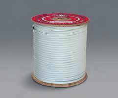
62 Continental Western Double Braid Rope Nylon Double Braid Rope 60 Polyester Double Braid Rope


63 STRONG-BAC Below/Hook Lifters Below/Hook Lifters for Cranes & Hoists The Caldwell Group Lifting Beams Spreader Beams Roll Lifters Coil Lifters & Upenders 61 Sheet Lifters Pallet Lifters Rotating Crane Hooks Lifting Tongs

64 Harrington LB Lever Hoists The LB Series of lever hoists offers a low headroom, compact design that is perfect for use in tight quarters. Regarded as the best lever hoist in the industry, our LB is recommended for use in heavy-duty construction work, mining, manufacturing, shipbuilding and day-to-day maintenance and repair. Many Benefits From More Features: Rugged, all-steel construction that actually weighs less than comparable aluminum models. Get positive braking action with Weston-style load brake Grade 100 heat-treated load chain is nickel plated for incorporating two moisture-resistant brake pads with corrosion resistance. four braking surfaces. Includes two brake pawls for Forged and heat-treated alloy steel hooks open slowly additional reliability. without fracturing under excessive loads. Top and bottom Enjoy protection against dirt and moisture with a totally hooks rotate 360. enclosed brake mechanism. Test certificate verifies that every hoist has been factory Ensure long life with machined, heat-treated, split load load tested to 125% of rated capacity, in accordance with double reduction gears. ASME B30.21 requirements. Operate in close quarters with short steel handle and 15-degree recovery strokes. Patented spring-loaded freewheel mechanism permits easy adjustment of the load chain and safeguards against accidental freewheeling under load. Equipped with standard rubber grip for non-slip operation. Capabilities To Count On: 5-foot lift is standard, 10-, 15- and 20-foot lifts also stocked; nonstandard lifts available as well Ton 3 Ton 6 Ton 9 Ton L B L E V E R H OIS T S P E C I F I C A T I O N S & D I MEN S I ONS Cap. (Tons) Product Code Headroom C Std. Lift (ft) Pull to Lift Load* (lbs) a b D* e f g Load Chain Diameter (mm) x Chain Fall Lines Net Weight (lbs) 3 4 LB (36) x 1 1 LB (46) (14.4) Shipping Weight Approx. (lbs) Weight for Additional One Foot of Lift (lbs) LB (45) x LB (42) (14.4) x LB (57) LB x LB (16.9) x LB x *Figures in parentheses are for hoists with the optional load limit warning handle. 0.5


65 Harrington CB Hand Chain Hoists Harrington CB hand chain hoists combine a rugged exterior shell with machined interior components to handle your most demanding lifting operations. An efficient drive train minimizes manual effort, while double enclosed brake cover, standard slip clutch, and double pawl springs enhance performance and reliability. Many Benefits From More Features: Experience exceptional durability thanks to all-steel construction featuring rugged gear case enclosure and handwheel cover. Enjoy increased lifting height thanks to low headroom. Compact design results in lightweight and easy portability. Minimize manual effort thanks to efficient drive train. Standard slip clutch device prevents the hoist from being used to lift damaging loads beyond rated capacity. Double pawl springs provide redundancy for reliable operation of brake mechanism. Get reliable braking with double enclosed brake cover that keeps out dust, rain, and dirt. Capabilities To Count On: 8-foot standard lift (12-foot for 10 Ton and greater), nonstandard lifts and hand chain drops are also available. Grade 100 heat-treated manganese alloy load chain resists abrasion and wear while minimizing chain weight. Forged and heat-treated alloy steel hooks are designed to open slowly, without fracturing under excessive loads. Test certificate verifies that every hoist has been factory load tested to 125% of rated capacity, in accordance with ASME B30.16 requirements Ton 3 5 Ton 8 15 Ton Ton C B H A N D C H A I N H O I S T S P E C I F I C A T I O N S C B H A N D C H A I N H O I S T D I M E N S I O N S Cap. (Tons) Product Code Headroom C 1 2 CB Std. Lift (ft) Pull to Lift Load (lbs) Overhaul Ratio Load Chain Dia. (mm) x Chain Fall Lines Net Weight (lbs) Shipping Weight Approx. (lbs) Weight for Additional One Foot of Lift (lbs) x CB x CB x CB x CB x CB x CB x CB x CB x CB x CB x x x CB x x x 2 40 CB x x CB x x x CB x x x CB x x x Please Note: Special lengths of load and hand chain available upon request. Weights are approximate. Cap. (Tons) Product Code a b d (ft) e f g x 1 2 CB CB CB CB CB CB CB CB CB CB CB CB CB CB CB CB

66 Harrington CF Chain Hoists Harrington CF hand chain hoists give you a practical alternative thanks to an economical design using fewer parts for trouble-free service. Outstanding durability is due to a die-cast aluminum body and high-strength, heat-treated main pinion shaft and load gear. Pre-lubricated ball bearings, precision machined gears, and Weston-style load brake make lifting smooth and easy while allowing long service and low maintenance. Many Benefits From More Features: Experience exceptional strength with a thick die-cast aluminum body. Handle tough demands with high-strength, heat-treated main pinion shaft and load gear. Get positive braking action with Weston-style load brake incorporating two moisture-resistant brake pads with four braking surfaces. Minimize manual effort thanks to smooth running, pre-lubricated ball bearings, and precision machined drive train components. Simplify maintenance with fewer parts and an easy-to-work-on design. 64 Capabilities To Count On: 10-foot lift is standard, 15- and 20-foot lifts are also stocked; nonstandard lifts and hand chain drops available as well. Grade 100 heat-treated manganese alloy load chain resists abrasion and wear while minimizing chain weight. Forged and heat-treated alloy steel hooks are designed to open slowly and not fracture under excessive loads. Test certificate verifies that every hoist has been factory load tested to 125% of rated capacity, in accordance with ASME B30.16 requirements Ton 2 3 Ton 5 Ton C F HAN D C H A I N HOIS T S P E C I F I C A T I O N S Cap. (Tons) Product Code Headroom C 1 2 CF Std. Lift (ft) Pull to Lift Load (lbs) Overhaul Ratio Load Chain Diameter (mm) x Chain Fall Lines Net Weight (lbs) Shipping Weight Approx. (lbs) Weight for Additional One Foot of Lift (lbs) x CF x CF x CF x CF x CF x Please Note: Special lengths of load and hand chain available upon request. Weights are approximate. C F HAN D C H A I N HOIS T DIM E N S ION S Cap. (Tons) Product Code a b 1 2 CF d (ft) e f CF g CF CF CF CF


67 Harrington LX Lever Pullers Harrington s LX mini puller is lightweight, compact and built to perform. It fits conveniently in a toolbox and will easily handle pulling and moving jobs in many applications including transportation, construction and plumbing. Available in two capacities to fit all applications. The 1 2 Ton capacity is unique to the industry. Many Benefits From More Features: Durable die-cast aluminum body with steel frame is compact and lightweight. Very low headroom design for use in tight spaces. Free-chain mechanism allows for quick adjustments. Extremely low pulling force is required for operation. Weston-style brake is totally enclosed to protect against dirt, dust and rain. Single step reduction gear assures load holding performance. Load chain guide mechanism permits smooth and quiet guiding of chain. Rubber handle grip for ease of use. Effortless to transport, install and store. Capabilities To Count On: Grade 100, nickel-plated load chain is corrosion and wear resistant. Strong hook latches include notched tip. 5-foot lift is standard. Longer lifts are available in both capacities. Sold individually or in convenient multi-packs 1 4 Ton in 6-packs and 1 2 Ton in 4-packs. Test certificate verifies that every hoist has been factory load tested to 125% of rated capacity in accordance with ASME B30.21 requirements Ton LX 1 2 Ton LX 1 4 Ton LX 1 2 Ton LX L X L E V E R P U L L E R S P E C I F I C A T I O N S & D I MEN S I ONS Cap. (Tons) Product Code Headroom C Std. Lift (ft) Pull to Lift Load (lbs) a b D e g Load Chain Diameter (mm) x Chain Fall Lines Net Weight (lbs) Shipping Weight Approx. (lbs) Weight for Additional One Foot of Lift (lbs) 1 4 LX x LX x Weights are approximate.

68 Harrington CX Mini Hand Chain Hoists Harrington s CX mini hand chain hoist is the world s smallest industrial hoist. This uniquely compact and lightweight hoist is the perfect choice for jobs with light loads in high or difficult to reach places such as duct installation, plumbing and heating, home automobile maintenance and crane repair. Many Benefits from More Features: Unique design is extremely compact and lightweight Aluminum body with steel frame provides superior strength. Load limiter prevents the hoist from being used to lift damaging loads beyond rated capacity. Very low force is required to lift load. Metal chain guide allows smooth operation. Effortless to transport, install and store. 66 Capabilities to Count On: Grade 100, nickel-plated load chain is corrosion and wear resistant. Strong hook latches include safety tip. 10-foot lift is standard, 20-foot lift is also stocked; nonstandard lifts and hand chain drops are also available. Sold individually or in convenient 4-packs. Test certificate verifies that every hoist has been factory load tested to 125% of rated capacity in accordance with ASME B30.16 requirements. 1 4 Ton CX CX003 C X M I N I HAN D C HAI N H O I S T S P E C I F I C A T I O N S & DIMENSI O N S Cap. (Tons) Product Code Headroom C Std. Lift (ft) Pull to Lift Load (lbs) Overhaul Ratio a b d (ft) e f g Load Chain Diameter (mm) x Chain Fall Lines Net Weight (lbs) Shipping Weight Approx. (lbs) Weight for Additional One Foot of Lift (lbs) 1 4 CX x CX x CX x CX x Weights are approximate.

69 Harrington PT Push Trolleys Harrington push and geared trolleys help you maneuver easily on your most demanding lifting operations. They feature specially designed contoured wheels that ensure reliable tracking, and their sealed ball bearings avoid maintenance hassles and provide smooth operation. Many Benefits From More Features: Get sure trolley tracking with specially designed contoured wheels that fit both tapered and flat-flange beams. Maintenance-free, sealed precision ball bearings are lubed-for-life and offer smooth movement, with low friction and long life. Get strength and rigidity from a lightweight, compact design. Easily adjust trolley to fit a wide variety of beam flange widths. Load equalizing suspension distributes the load to all wheels. Wide standard flange ranges reduce the need for optional extended shaft kits. Match the needs of the job with a variety of trolley hoist suspenders. Capabilities To Count On: Use the economical PT for applications involving longer traversing distances. 1 2 through 3 Ton are supplied with Suspender C, which is suitable for most applications. Alternate suspenders may be required for your application Ton 5 10 Ton P T P U S H T R O L L E Y S P E C I F I C A T I O N S & D I MEN S I ONS Cap. (Tons) Product Code Min. Radius for Curve Standard 1 2 PTF to PTF to 5.00 Flange Width Adjustability B Option 4.01 to 8.00 or 8.01 to to 8.00 or 8.01 to a max a' b e h i j k m n r s t v Net Weight (lbs) Shipping Weight (lbs) B B PTF to to B PTF PTF to to PT PT100 Weights are approximate B to to B


70 Harrington GT Geared Trolleys Harrington push and geared trolleys help you maneuver easily on your most demanding lifting operations. They feature specially designed contoured wheels that ensure reliable tracking, and their sealed ball bearings avoid maintenance hassles and provide smooth operation. Many Benefits From More Features: Get sure trolley tracking with specially designed contoured wheels that fit both tapered and flat-flange beams. Maintenance-free, sealed precision ball bearings are lubed-for-life and offer smooth movement, with low friction and long life. Get strength and rigidity from a lightweight, compact design. Easily adjust trolley to fit a wide variety of beam flange widths. Load equalizing suspension distributes the load to all wheels. Wide standard flange ranges reduce the need for optional extended shaft kits. Match the needs of the job with a variety of trolley hoist suspenders. Capabilities To Count On: Use the GT for precise load control and shorter traversing distances. 1 2 through 3 Ton are supplied with Suspender C, which is suitable for most applications. Alternate suspenders may be required for your application. Geared trolleys of larger capacities are available. Please consult factory for details. 68 G T G E A R E D T R O L L E Y S P E C I F I C A T I O N S & D I M E N S I O N S Cap. (Tons) Product Code Min. Radius for Curve Standard GTF to 5.00 Flange Width Adjustability B Option 5.01 to 8.00 or 8.01 to a max a' b e f* (ft) h i j k k' m n r s t B u v Net Weight (lbs) GTF to to B GTF GTF to to GT GT GT GT *Longer hand chain drops available upon request. Weights are approximate Ton Ton Ton Shipping Weight (lbs) B to to B


 Product Code Flange Range D Max. Beam Flange Thickness Max. E F G H J A UBC Suspender Option B C T Net Weight (lbs)* 1 UBC010 8 10 3.00 to 7.50 0.83 12.25 3.00 9.25 0.88 2.")
71 Harrington Universal Beam Clamps Harrington s UBC Universal Beam Clamp is the perfect accessory when a temporary or semi-permanent hoist anchor point is required. Additionally used as a belowthe-hook lifting attachment, this adjustable beam clamp offers an efficient, cost effective method for most workholding and positioning applications. Available in capacities of 1, 2, 3, 5 and 10 Tons. Easy Operation Lightweight portable design Left-hand and right-hand clamp screw allows for quick clamping and unclamping Jaw opening adjusts for a wide range of tapered or flat-flanged beams Optional UBC suspender for perpendicular mounting and for oversized hooks Applications Industrial and construction lifting applications Overhead lifting and vertical rigging operations Holding and positioning beams for construction MODEL: UBC030 MODEL: UBC030 WITH UBC SUSPENDER OPTION Dependability and Design Meets ASME BTH-1, ASME B30.20 and complies with portions of ASME B30.16 for use with manual and powered hoists Design factor minimum of 5:1 per ASME B30.16 requirements Lock nut feature resists loosening to improve secure clamping Built-in suspension pin for low headroom Metric rated capacity Each Universal Beam Clamp is individually serialized and load tested (test certificates included) Made in the USA 69 Universal Beam Clamp UBC Suspender Option U B C U N I V E R S A L B E A M C L A M P S P E C I F I C A T I O N S A N D D I M E N S I O N S Capacity (Tons) Product Code Flange Range D Max. Beam Flange Thickness Max. E F G H J A UBC Suspender Option B C T Net Weight (lbs)* 1 UBC to UBC UBC to UBC UBC to *The weights listed are for standard universal beam clamps without large suspenders. Shipping Weight Approx. (lbs)*


72 BC Wire Rope Fall Protection Overview Competent Person in Fall Protection T R Cert # BC001 A I N E D Fall Protection Authorized Person of Fall Protection T R A I N E D Welcome to BC Wire Rope and Rigging Fall Protection, our mission is to provide BC Customers with the best fall protection product at a reasonable price for the at-risk Worker at height, and to promote its proper use. BC Wire s commitment doesn t just start & end with providing quality fall protection product, our expertise will help you get the right tool for the right job, right away. As a Proud Member of ANSI, and our Anaheim Branch an ISO 9001 Certified Facility, BC Wire Rope and Rigging goes to great lengths to ensure that all fall protection product and consultation provided meets or exceeds, and speaks to OSHA 1926 Guidelines and ANSI Z359 Standards. 70 Certified Anaheim Location Only

73 Premium Safety Harnesses BC Wire Rope Fall Protection maintains a full inventory of harnesses and anchorages. BC recommends the DBI ExoFit and DBI ExoFit NEX as the best overall harnesses in terms of comfort, wear and durability. We always carry plenty of both in stock, along with our full inventory of harnesses from other vendors, for immediate will call or delivery. Fall Protection ExoFit Medium Built-in shoulder, back and leg comfort padding Back D-ring Body belt/hip pad with side D-rings Quick connect chest and leg straps Soft, lightweight webbing Anti-tear ballistic nylon Built-in reflective piping Parachute torso adjusters Protected labels, equipped with i-safe DBI ExoFit Product Overview: ExoFit Construction Style Positioning Harness - Model # Back D-ring, belt with pad and side D-rings, quick connect buckle leg straps, built-in comfort padding (size X-Large) ExoFit NEX Medium Hybrid shoulder, back & leg comfort padding Stand-up Tech-Lite aluminum back D-ring Body belt/hip pad with Tech-Lite aluminum side D-rings Duo-Lok quick connect chest and leg straps Repel webbing & Protective shoulder caps Built-in lanyard keepers Revolver vertical torso adjusters Impact Indicator Integrated trauma straps Built-in reflective materials Protected labels, equipped with i-safe DBI ExoFit NEX Product Overview: ExoFit NEX harnesses are the most advanced harnesses in the industry. They re the culmination of the ExoFit and ExoFit XP, ongoing research and the incorporation of new materials and innovative features. True to the NEX mission, DBI manufactures these harnesses using materials that won t add unnecessary weight for ultimate comfort. When speed and efficiency are project requirements, ExoFit NEX will provide the freedom and confidence to function at your maximum potential. Finally, ExoFit NEX harnesses are designed using materials that last. Get into the best, the ultimate comfort, function and durability harness, ExoFit NEX.

 Torso keeper for stowing idle lanyard connector Paired mating buckle adjusters on front torso FallTech Contractor Harness Product Description: Special Priced Item Tradesman")

74 Economical Safety Harnesses Delta Comfort Harness Built-in shoulder, back and leg comfort padding Fixed back D-ring Rigid body belt and hip pad with side D-rings Tongue buckle leg straps Durable, lightweight polyester webbing Built-in lanyard keepers with break-away feature Revolver vertical torso adjusters Impact Indicator Protected labels, equipped with i-safe DBI Delta Comfort Harness Product Overview: BC Wire Recommends the DBI Delta Comfort Harness as an economical alternate to the DBI Exofit 72 Contractor Harness 5 points of adjustment (chest, legs and torso) Torso keeper for stowing idle lanyard connector Paired mating buckle adjusters on front torso FallTech Contractor Harness Product Description: Special Priced Item Tradesman Plus Construction Harness 3 D-rings, Back and Side Tongue Buckle Legs and Quick Connect Chest Enhanced webbing for greater durability and comfort Tri-layer air mesh shoulder yoke and waist pads for greater comfort Durable 6" Waist and 10" Shoulder Pads FallTech Tradesman Plus Construction Harness Product Description: Special Priced Item. Best features for a Construction Harness under $100.


75 Fall Protection Anchorages BC Wire Provides a variety of Anchorage Solutions, below are a few suggested options. BeamWalker - Sliding Beam Anchor Lightweight aluminum anchor Adjusts from both sides Beveled sliders allow smooth movement along the beam moving with the worker Can be used at foot level but must be used with a 12 extended free fall energy absorbing lanyard Veri5000 Anchorage Verification Device Designed for proof-tests on fall protection and construction anchors Custom bridge and legs built for testing anchorage to verify OSHA/ANSI requir ements and anchor performance criteria Provides a proof-test and documentation through a downloadable application with Bluetooth technology After proof-testing an anchor self-laminat ing tags with zip ties can document that the anchor has been verified Rotating D-Ring Anchor Ring Anchor rotates 360 and pivots 180 to meet User's movement and load direction should a fall event occur Includes Rotating D-Ring Anchor without fasteners For permanent or temporary moveable installation with User Supplied fasteners Tensile Strength: 5,000 lbs Min ANSI User Capacity: 130 to 310 lbs Max OSHA User Capacity: 130 to 425 lbs Max Complies with ANSI Z and OSHA


76 Tuff Built TriPost Trench Plate Anchor TriPost for Trench Plate Anchor Base Screws Into Standard Trench Plate 360 Degree Anchor Points for 3 Workers Height Adjustment with Tuff-Klik Technology Workers Must Use SRL Pro-3 Tripost 74 Part # 30184: Tripost Pro-3 with 3 Anchor Points Part # 30184: Base TriPost Mount for Trench Plate Safe Working Zone Mobile SafeLINK Horizontal Lifeline System Specifically for Low Clearance Heights Lifeline Minimum Fall Clearance Required* Span 1 User 2 Users 3 Users 4 Users 15 ft 7'0" 7'0" 7'0" 7'6" 20 ft 7'0" 7'0" 7'4" 7'8" 25 ft 7'0" 7'4" 8'0" 8'4" 30 ft 7'0" 7'8" 8'4" 8'8" 35 ft 7'9" 8'5" 9'1" 9'5" 40 ft 8'5" 9'1" 9'9" 10'2" 45 ft 9'2" 9'11" 10'8" 11'0" 50 ft 9'11" 10'7" 11'3" 11'8" 55 ft 10'6" 11'2" 12'0" 12'4" 60 ft 10'10" 11'10" 12'6" 12'11" 65 ft 11'10" 12'6" 13'0" 13'6" Radius The SAFELINK Portable Horizontal Lifeline System is designed for working at low heights in the construction industry. The system in engineered to provide optimum fall protection on leading edge projects with limited anchorage options. The STOPLINK energy absorber limits braking forces enabling versatility in fall protection coverage. Horizontal Lifeline Diagram
 and with the optional bypass brackets, the system can be configured to run indefinitely for ultimate jobsite flexibility.")

77 DBI/Capital Safety SecuraSpan Extremely lightweight and portable, these systems incorporate a modular, multi-base design that accommodates a wide range of steel and concrete beams. Spans can be up to 60 ft. (18.3 m) and with the optional bypass brackets, the system can be configured to run indefinitely for ultimate jobsite flexibility. You can always depend on our horizontal safety systems for mobility and fall protection when working at height. These systems are used to protect workers operating in the horizontal plane who may not have continuous access to suitable anchorage points SecuraSpan Complete 60 ft. (18.3 m) system includes two stanchions and cable assembly Rugged 3/8" (9.5mm) 7x19 galvanized cable lifeline Fits I-beam flanges 6 in. to 12 in. ( cm) up to 2-1/4" (5.7 cm) thick Lightweight and portable design Top mounted adjustment system Simple clamp and wing nut installation Extremely durable construction Single and multi-span indefinite length system configurations Pass-thru 100% tie-off protection Zorbit energy absorber limits fall arrest forces Flexible system capacity Various lengths and individual components are available Equipped with i-safe 75 DBI/Capital Safety EZ-Line Horizontal Lifeline System EZ-Line 60 ft. (18.3 m) retractable system can be set at any length Rugged 1/4" (6.3mm) 7x19 galvanized cable lifeline Ergonomic easy to carry case Extremely lightweight and portable design Built-in winch, pre-tension and impact indicators Durable construction will stand up to tough jobsites Single and multi-span (with SecuraSpan stanchion) system configurations Internal energy absorber limits fall arrest forces Flexible system capacity Use with any 5,000 lb. (22.2 kn) anchorage device Equipped with i-safe


78 Self-Retracting Lifelines BC Wire Rope Proudly stocks DBI & FallTech Self-Retracting Lifelines. As a Proud Member of ANSI, we suggest using SRL s built in compliance to Z Whether for work positioning or fall arrest, BC Wire Rope stocks only the best ANSI Z359 Compliant lanyards at competitive prices Rebar Chain Assembly Swivel Steel Rebar Hook with 2.5" Gate Opening Clevis-pin Steel Snap Hooks Grade 80 Chain BC Wire Special Price Item Extended Free Fall Y Lanyard Rated for a 12 free-fall, 310 Lbs. Worker Choke on loop in lieu of snap hook eliminates rattling connective hardware Accessory Dee ring for transitioning to an SRL or Rescue Light Weight Aluminum ANSI Z compliant Rebar Hooks BC Wire Special Price Item Rebar Chain Assembly Description: Rebar Chain Assembly Positioning Device Swivel Rebar Hook 2 1/4 Inch Opening 3/4 Inch Snap Hooks Grade 100-9/32" Chain Technical: Part Number: RBCS211 Body Material: Steel Maximum SWL : 400 lbs. (158kg) Standards: Standards: Compliant with all OSHA 1910, OSHA 1926 Subpart M, ANSI Z , and ANSI A For Positioning Only


 Other lengths available up to 100 ft. (30.5 m) ANSI Z359.")

79 Rescue Products BC Wire Rope highly recommends the Rollgliss R550 Rescue System. The Rollgliss R550 offers the choice of controlled descent rescue, evacuation or the versatility of assisted rescue with lifting capabilities. This state-of-the-art, fully automatic controlled descent device can be used for rescue and evacuation from heights up to 1,640 ft. for one user 310 lbs. or 575 ft. for two users totaling 620 lbs. It features 3/8 in. super static kernmantle rope, and is configured with connecting hardware at each end of the lifeline to operate in both directions. During assisted-rescue scenarios, a fallen worker can be attached to the R550 device, raised to a point that allows their fall arrest device to be removed, then lowered to the ground safely Self-Rescue 50 Universal harness attachment EZ-Link D-ring for fast connections 50 ft. of 5.5 mm rope Assisted-rescue ring for incapacitated user Sealed descent device and rope spool extends longevity Molded padding provides durability and comfort Lightweight, low profile design Equipped with i-safe Optional rescue pole available (model ) Other lengths available up to 100 ft. (30.5 m) ANSI Z359.4 Compliant Rescue Plan for the low at risk worker at height 77 Confined Space Rescue Products BC Wire Rope is a Proud Disctributor of the Innova Xtirpa, the lightest portable confined space fall protection/ retrieval system on the market! Sets up in seconds, the Xtirpa is simple as it is innovative. IN-8010 XTIRPA Xtirpa Davit-Arm, Mast and Adjustable Adapters are designed for applications involving frequent set ups over similarly-sized access openings. This lightweight and easy to assemble/disassemble system provides a portable adapter base and certified anchor point. Ideal option for areas where a permanent anchor is not viable. IN-8010 XTIRPA Manhole guard systems are used when an exposed entry point needs to be guarded. This portable system has an integrated mast which is used in conjunction with a davit arm to provide fall protection, entry and retrieval capabilities. The manhole guard system facilitates access to underground chambers or any other type of confi ned spaces where an entry point should be protected. Davit arm is equipped with 5000 lb. ( 2268 kg ) anchor point.


80 Protecta Roofers Kit Compliance in a Can is often imitated, but never matched. Protecta pioneered the creation of a complete fall protection system available in a convenient container. The success of the original can spawned the creation of several variations with different anchorage devices. Each kit offers a complete set-up including an anchorage device, body support and connecting component for convenient compliance and safety on the job. This ABC s approach to fall protection simplifies the buying decision and makes choosing the correct system simple, fast and safe. Our easy to use kits and anchorage devices provide the perfect solution and are legendary for their performance, value, quality and safety. 78 PROTECTA Roofers Kit Complete roofer's fall protection system in one handy container Reusable and extremely durable roof anchor with fasteners (model AJ730A) Lightweight FIRST harness with pass-thru buckle legs and 5-point adjustment (model ) Compact rope adjuster with built-in 2 ft. (0.6m) PRO shock absorbing lanyard (model ) Durable and lightweight 5/8" dia. (1.6cm) 50 ft. (15.2m) blended lifeline with snap hook (model ) Durable bucket with handle Compliance in a Can Included in the Roofers Kit: PROTECTA PRO Reusable Hinged Roof Anchor Reusable hinged roof anchor for flat or sloped wood roofs with D-ring and fasteners. Model # AJ730A PROTECTA PRO Rope Adjuster with Lanyard Manual rope adjuster with 2 ft. PRO shock absorbing lanyard for use on 5/8" rope lifeline. Model # PROTECTA FIRST Vest-Style Harness Back D-ring, pass-thru buckle leg straps (size Universal). Model # PROTECTA Rope Lifeline with Snap Hook 50 ft. polyester/polyproplene blend 5/" diameter rope lifeline with snap hook at one end Model #


81 Fall Protection for Tools Fallen Objects are one of OSHA s Focus Four, BC Wire Rope is proud to stock DBI Fall Protection for Tools. Ensure that you are in OSHA compliance and Stop the Drop. Stop the Drop Fall Protection for Tools 3M DBI-SALA Fall Protection for Tools makes work environments safer and more productive by drastically reducing falling object incidents resulting in personal injury, equipment damage, and tool loss. Our drop prevention solutions are designed with the craft in mind, and are third-party tested in the harshest possible conditions. Learn more about our comprehensive collection of tool lanyards, tool holsters, attachment points, and other drop prevention products. 79 Certified and Tested Our onsite ISO accredited lab allows us to simulate heat, cold, moisture, corrosion and abrasion the challenges you face every day. We conduct dynamic and static strength tests, both in the field and in our ISO certified manufacturing facilities, ensuring you get the highest quality, most reliable fall protection for tools.


82 Horizontal Lifeline Systems Whether temporary or permanent fall arrest or traveling restraint, BC Wire Rope can help. We specialize in fall protection solutions that are OSHA Compliant and cost effective FlexiGuard SafRig Freestanding jib fall arrest system Provides overhead tie-off point for vehicle maintenance worker 6.1 m anchor height 1.75 m offset from mast Jib rotates 360 degrees Freestanding outrigger base with forklift pockets Drive over outrigger design System does not require any vehicle counterweight High strength durable steel construction Integrated rescue device mounting hardware Custom designs also available Specialised installation and training available 80 The FlexiGuard SafRig with Outrigger Base is a portable solution for indoor and outdoor maintenance where mobility and worker safety are key. These systems incorporate a 360 rotating jib with the capacity to provide fall protection for one person. Forklift pockets are strategically located on the base to ensure ease of mobility and placement from job site to job site. The base is also designed to easily drive over, and the system does not require the weight of the vehicle as the anchor force for complete flexibility. These systems are OSHA compliant. Our anchorage connectors are built from top quality materials guaranteeing high strength and durability to stand up to the toughest environments. Anchorage connectors are the unsung heroes of most fall protection systems, often overlooked but critical components because they securely attach your system to the anchorage Roof Top Anchor Installs to single ply bitumin membrane and built-up type roofs For use on flat or sloped (up to 3:12 pitch) Fastens through membrane, insulation and into metal, wood or concrete Multiple fastener options available Exclusive design offers fast installation Complete with shroud for bitumin offering maximum weather proofing Aesthetic design compliments the roof Thermal efficient design and construction Load distributing design protects roof and user Swiveling tie-off point for complete mobility Compatible with various fall arrest connecting systems Multi-person use with horizontal lifeline system
83 Competent Person in Fall Protection Classes BC Wire Rope and Rigging s Competent Person in Fall Protection Program is designed for the Construction Professional, usually in a Leadership Role (Superintendent, Safety Manager) responsible for hazard identification and mitigation for the at-risk Worker at Height. BC Wire Rope and Rigging s Three (3) Day Competent Person in Fall Protection Course satisfies the Training requirements of OSHA 1926, 1910, ANSI Z , Z , Cal OSHA Title 8, & Army Corps of Engineers EM 385. BC Wire s Competent Person in Fall Protection Course is not a Generalist, check the box Program. It also isn t an outdated power point simultaneously speaking to all Trades at various level of skill. The BC Wire Competent Person in Fall Protection Course lesson plan is different in that it s Customized & Trade specific for each respective Organization. Customized & ANSI Compliant Training ANSI Z states that as part of a Managed Fall Protection Program, a Competent Person in Fall Protection shall be trained by either a Competent Person Trainer or Qualified Person Trainer. These trainers have documented experience, knowledge, training, and education equal to or greater than any category of person that they are training as it relates to fall protection & documented experience, knowledge, and skills in adult education. Collaborative Curriculum BC Wire Rope will collaborate to include a Companies fall protection Policies and Procedures into the Course An Authorized Person Course Template (Power Point, Test/ Training Materials, Inspection Forms) will be provided for your Organization s ongoing use. 21 In addition to fall hazard identification/ mitigation, successful completion includes competencies in the following: Fall Protection program management, Company Policy & Procedures and record keeping Passive Fall Protection and Regulatory Compliance Hierarchy of Fall Protection Slips, trips, controlled access & decking zones Best Practice while working in Scissor or Boom Lift How to select & properly use a task-specific, Personal Fall Arrest System (PFAS) Identification and proper use of non-certified Anchor Points CP Traveling restraint and work positioning systems Proper Installation and use of temporary horizontal lifelines (synthetic and cable) OSHA 1926, 1910 Guidelines and ANSI Z Standards for a Managed Fall Protection Program Z Environmental Health and Safety Training, EM 385 Army Corps of Engineers Ladder Safety Leading edge applications and extended free fall Proper documentation of Job Hazard Analysis Surveys/ Site Specific Safety Surveys Adult Learning methods and practical demonstration of the Authorized User of Fall Protec tion lesson plan Competent Inspection and documentation of fall protection equipment Assisted and Unassisted Rescue in pre-planning and application, Orthostatic Intolerance and Post- Fall First Aid Competent Person in Fall Protection T T R R A A I I N N E E D D oauthorized User of Fall Protecti n Certified


84 Perimeter Protection Products Systems Fast Installation and Removal Decrease Leading Edge Exposure by 87% OSHA Compliant Versatile and Reusable 82 Use Perimeter Protection Posts During Construction: At Building Perimeter Between Columns This Dinosaur is Costing You Money! At Building Perimeter at Roof Level Around Elevator Shafts Around Stair Well Openings Did you know? PPP is the only perimeter protection company that customizes its products for a customer's specific needs.


85 Fall Protection Netting Systems Debris Fall Protection Cargo Custom Save both time & money with these turnkey systems. There is typically only a 1 week lead from design to install. These systems use non-penetrating brackets & have a 15 cantilever vs 10 with most others. Debris Systems Horizontal/Vertical Netting 3/16" Polyester Mesh Opening Fire Retardant Coating Double Seat Belt Border Center Grommets every 1' Multiple Colors Custom Sizes Full Turnkey Design Professional Installation Available Custom Systems Orchestrated Pits Elevator Shafts Sky Light Openings Fall Protection Systems 3/16" Single 2"x2" Mesh Nylon Rope Netting UV Protected Rated to 17,500 lbs Meets ANSI Standards for FP Netting Includes High Visibility 5/8" Polypro Rope Border Custom Lengths 83


 Three Dee Ring Construction")
86 Web Devices Custom Harnesses H12353 H39112 H12151 Customize the Colors of Your Company s Harness, Add Logo with BC Wire Rope Easy Recognition of Company Employees on Jobsites Helps with Loss Prevention No set up fee or upcharge, just a Minimum quantity purchase of 20 Harnesses or more Hand Sewn, ANSI Z359 & CSA Compliant Harnesses from Web Devices with a Limited Lifetime Warranty. Proudly Made in the USA 84 Build Your Company s Fall Protection Harness in Three Easy Steps: 1. Choose Preference of Leg Straps; Tongue and Buckle, Pass-Thru or Quick Connect 2. Choose from any Two Available Colors (top/ bottom) 3. Submit a JPEG, GIF or PDF of Company Logo (for heat transfer on back strap) Three Dee Ring Construction Style Harnesses & Roofers Kits are also available for Customization, please speak with a BC Wire Representative for more information.


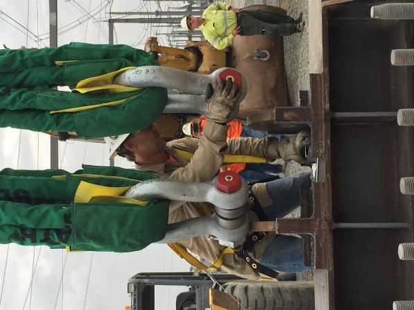
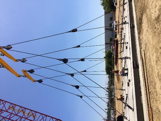


87 BC ON THE JOB


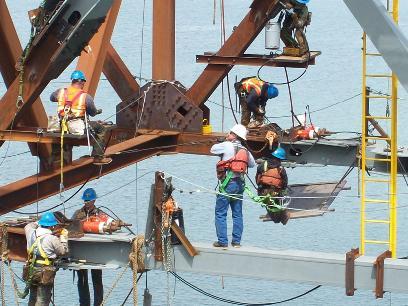

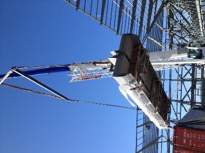


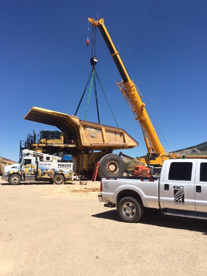
88 OUR PRODUCTS TACKLE SOME OF THE BIGGEST JOBS AROUND BCGC-2017 Anaheim Only Fall Protection
AMERICAN. ANAHEIM 2720 E. Regal Park Dr. Anaheim, CA Phone: Fax: IDEAS AT WORK ARIZONA CALIFORNIA NEVADA
 O ARIZONA CALIFORNIA NEVADA SAN DIEGO 10717 Airport Dr. El Cajon, CA 92020 Phone: 619-270-2030 Fax: 619-270-2035 Quality, No Compromise Since 1974 LAS VEGAS 7491 Eastgate Rd Henderson, NV 89015 Phone:
Health & Safety Policy and Procedures Manual SECTION 25 RIGGING AND HOISTING EQUIPMENT
 SECTION 25 RIGGING AND HOISTING EQUIPMENT 1. RIGGING AND HOISTING: These rules apply to all Maul Electric, Inc. employees and subcontractors. Note: Maul Electric, Inc. employees will utilize mechanical
Crosby: There is No Equal
 Forged Clips The Market Leader: Yesterday, Today and Tomorrow G-450 G-429 Crosby: There is No Equal FORGED FOR CRITICAL APPLICATIONS The proper performance of forged clips depends on proper manufacturing
Visit: 27
 Visit: http://www.kwrs.com 7 SINGLE PART SLINGS Eyes are typically formed using a flemish eye splice. The ends are secured by pressing a metal sleeve over the ends of the strands of the splice. Pull follows
Crosby Wire Rope End Fittings WIRE ROPE END FITTINGS. With Product Warning and Application Information
 Crosby Wire Rope End Fittings WIRE ROPE END FITTINGS With Product Warning and Application Information G-450 FORGED FOR CRITICAL APPLICATIONS The proper performance of forged clips depends on proper manufacturing
For Review Only No Copying No Saving No Lending No Posting Online
 The following copyrighted samples are provided as a service for your review only. Copying, saving, lending, posting online or any general use of these files other than for the purpose provided is unlawful
Heavy Equipment & Rigging Specialist Training
 Heavy Equipment & Rigging Specialist Training Module 1 Unit 4: Intro to Rigging May08 1 Key Points Review of Exercise Goals Discuss Rigging Components Language of Crane Signals Review Anchor Installation
Another. N e w P r o d u c t. From:
 Another N e w P r o d u c t Metric ROV PRODUCTS: G209R ROV Shackle for Remote L562A Shank Hooks Operated L562A Shank Hooks L320R Eye Hooks From: Vehicles www.thecrosbygroup.com Crosby ROV Hooks and Shackles
CORPORATE SAFETY MANUAL
 CORPORATE SAFETY MANUAL Procedure No. 32-0 Revision: Date: May 2005 Total Pages: 10 PURPOSE To provide general guidelines for the inspection of all ropes, chains, cables, slings, etc. used for personnel
LiftAlloy Chain Slings
 CHAIN SLING BASICS Slings Lift-All chain slings meet or exceed all OSHA, ASME B30.9 and NACM standards and regulations. chain slings, available in 80 for 7/8"- /4" and 00 for 7/32"-3/4", are recommended
VGD WIRE ROPE HARDWARE
 VGD WIRE ROPE HARDWARE This is at your service Since 1960, Steel Ltd., a sister Company of Ringball Corporation, has been supplying specialty steels and steel products to North American Industries. By
Premium PowerPoint Presentation. Rigging Review
 Premium PowerPoint Presentation Rigging Review Chapter 1 Hoisting Safety Review: What about the CG Symmetrical vs. Asymmetrical Balanced and Unbalanced Lifting Lug Hooks Angle Deformation Safety Gates
WEBMASTER 00 SLINGS master 00 Polyester Slings Hardware Slings (TYPES U, AND ) Standard duty master 00 is designed for less frequent, light duty servi
 Standard duty master 00 is designed for less frequent, light duty servi") Best in Abrasion Resistance Available in two strength classes, all Dura- slings feature premium abrasive resistant yarns covering all surfaces, for extended sling life and long term value. Dura- Features,
Best in Abrasion Resistance Available in two strength classes, all Dura- slings feature premium abrasive resistant yarns covering all surfaces, for extended sling life and long term value. Dura- Features,
A & M Sales Offers a complete Line of Winch Line Rope. Bumper Mount Winch
 a & m sales, inc. p.o. box 171 chagrin falls, ohio 22 () 78-18 A & M Sales Offers a complete Line of Winch Line Rope Bed Mount Winch Just give us a call and we can walk you through the process of ordering
Basic Rigging And Wire Rope
 Basic Rigging And Wire Rope Presented By Master Builders of Iowa Basic Rigging and Wire Rope Topics Four Commandments of Rigging Sling Angles Types Of Hitches Types Of Slings Types Of Rigging Devices OSHA
Wire Rope End Terminations
 Wire Rope End Terminations s n o i t a n i m r e T d ne e p o R e r i W Wire Rope End Termina tions Copyright 2002 The Crosby Group, Inc. 25 Forged Wire Rope Clips What It Takes To Be G-450 G-429 FORGED
THOR 10 HAMMER CAGE INSTRUCTIONS
 75 " 7m 78 4" m 6" 8.8m 45 ".70m 4.9deg 6 4" 6m 44 4".67m 75 " 7m 9 4" 0m 44".m 497 4".64m The 70, Thor Hammer Cage, consists of four heavy duty aluminum net poles. The unique pole structure reduces the
Hoist Ring Forged Hoist Ring Machined Hoist Ring (Metric) Hoist Ring Swivel Shoulder Eyebolts JD Weld-On Alloy Lifting
 Hoist Ring Swivel Shoulder Eyebolts JD Weld-On Alloy Lifting") Hoist Ring Forged........................... 94 Hoist Ring Machined........................ 95 Hoist Ring (Metric).......................... 96 Hoist Ring Swivel........................... 97 Shoulder
Hoist Ring Forged........................... 94 Hoist Ring Machined........................ 95 Hoist Ring (Metric).......................... 96 Hoist Ring Swivel........................... 97 Shoulder
LiftAlloy TM Chain Slings
 LiftAlloy TM LiftAlloy CHAIN SLING BASICS Lift-All chain slings meet or exceed all OSHA, ASME B30.9 and NACM standards and regulations LiftAlloy chain slings, available in grade 00 for 7/32" through 3/4",
Winchline n a box WINCH LINE SELECTION GUIDE. Wire Rope Winchlines are superior to most other winchlines found in the market place due to the
 Winchline n a box Wire Rope Winchlines are superior to most other winchlines found in the market place due to the eye) end terminations. Each eye is protected by a steel liner (thimble) to guard against
2017 PRODUCT CATALOG. Nelson Wire Rope Corporation 3051 Penn St. Hatfield, Pennsylvania United States of America
 2017 2016 2017 PRODUCT CATALOG Nelson Wire Rope Corporation 3051 Penn St. Hatfield, Pennsylvania 19440 United States of America Tel: 215-721-9333 Fax: 215-721-0887 sales@nelsonwirerope.com www.nelsonwirerope.com
Mooring & towing. 9. Mooring & towing. Index
 Mooring & towing 9. Mooring & towing 1 General 1.1 About Hendrik Veder Group 1.2 Trade names 1.3 Certified Quality 1.4 Certificates 1.5 Key suppliers & brands 1.6 Contact information 1.7 Locations 1.8
MoBiLe CrAnes. surelift. B y W i r e r o p e i n d u s t r i e s. tower CrAnes. port CrAnes
 MoBiLe CrAnes tower CrAnes overhead CrAnes port CrAnes 004-14-201-WR203-06/00 Printed in Canada on Recycled Paper performance series performance series ropes For MuLti-purpose AppLiCAtions Backed by over
MATERIAL HANDLING - FIELD RIGGING SAFETY PROGRAM
 Title: Material Handling - Rigging Effective Date: 12/4/2014 Control Number: THG_0049 Revision Number: 1 Date: 10/23/2015 Annual Review Completed: 5/13/2015 MATERIAL HANDLING - FIELD RIGGING SAFETY PROGRAM
CONTENTS. Ranger Product Catalogue LIFTING CHAIN SLING OVERVIEW
 LIFTING CHAIN SLING OVERVIEW INTRODUCTION 2-12 Clevis Grab Hook & Eye Shortening Grab 36 About Ranger 2 Shortening Claw - VIP & Multi 37 Lifting Overview 3 Sling Hook with Latch - Clevis & Eye 38 Self
USER S GUIDE LIFTING TERMINOLOGY
 USER S GUIDE LIFTING API RP2D Version (06/06) REFER TO API RP2D FOR FULL DETAILS RISK MANAGEMENT DEFINITION COMPREHENSIVE SET OF ACTIONS THAT REDUCES THE RISK OF A PROBLEM, A FAILURE, AN ACCIDENT Quality
Product Information Brochure
 Proud Member Since 1984 Product Information Brochure Rigging, Contractors & Industrial Supplies 2 Be humble, be proud and take care of your team and they will take care of our customers. Everything else
Lift-All Wire Rope & Slings
 WIRE ROPE AND SLING BASICS Lift-All & Slings Two major and opposing characteristics of wire rope slings are flexibility and resistance to abrasion. To a great extent, these traits are a direct function
SECTION 15 RIGGING. b. Defective rigging shall be removed from service.
 SECTION 15 RIGGING 15.A GENERAL 15.A.01 Inspection and use. a. Rigging equipment shall be inspected as specified by the manufacturer, by a Competent Person, before use on each shift and as necessary during
Visit: 45
 Visit: http://www.kwrs.com Type Triangle Choker Nylon or Polyester web slings with alloy steel or alloy aluminum end fittings, for use vertical, choker, and basket hitch applications. Vertical Choker Basket
Heavy Equipment Technician Rigging
 1. What is SWL? a. Single weight of load b. Second weakest location c. Working load limit Heavy Equipment Technician IP Red Seal Practice Exam d. Abbreviation for swivel Heavy Equipment Technician Rigging
Roughneck TM Mesh Slings
 Roughneck TM Slings ROUGHNECK WIRE MESH SLINGS Widely used in metalworking shops and steel warehouses where loads are abrasive, hot or tend to cut web slings Features and Benefits Promotes Safety Steel
Crane & Rigging Brain Teasers
 Crane & Rigging Brain Teasers Host: Mike Parnell President/CEO, ITI ASME B30 Vice Chair (Cranes & Rigging) ASME P30 Chair (Lift Planning) The views expressed in this presentation are that of ITI and are
6036 Triple Sheave INSTRUCTION MANUAL
 INSRUCION MANUAL 6036 riple Sheave Read and understand all of the instructions and safety information in this manual before operating or servicing this tool. 9998057 009 Greenlee extron Inc. IM 98 REV
Proof load is the load applied in performance of a proof test. Proof test is a nondestructive tension test performed by the sling manufacturer or an
 1910.184 Slings (a) Scope. This section applies to slings used in conjunction with other material handling equipment for the movement of material by hoisting, in employments covered by this part. The types
8012, 8018 & ,000 LB. CAPACITY HOOK-TYPE CABLE SHEAVES
 OPERATION, SERVICE AND PARTS INSTRUCTION MANUAL 80, 808 & 804 8,000 LB. CAPACITY HOOK-TYPE CABLE SHEAVES Read and understand this material before operating or servicing this sheave. Failure to understand
RIGGERS SAFETY SAFETY IS IN THE DETAILS FULL LINE CATALOG
 RIGGERS SAFETY SAFETY IS IN THE DETAILS FULL LINE CATALOG Riggers Safety is a California-based manufacturer of Personal Fall Arrest Systems (PFAS) and Fall Prevention Products. Our automated manufacturing
Distribution. Experience Matters.
 Distribution Experience Matters. Steel Wire Rope Steel Wire Rope Slings The Partnership Usha Martin a leading manufacturer of a wide and diverse range of quality wire ropes suited for almost all applications.
Managing Mobile Crane Hazards. Paul Satti Construction Safety Council. Hazards of Working Around Cranes. Key Concepts:
 Managing Mobile Crane Hazards Paul Satti Construction Safety Council Hazards of Working Around Cranes Key Concepts: Electrocution Hazards Caught-In, Compressed or Crushing Hazards Struck-By Hazards Other
Hoisting Equipment Cable puller & Accessories
 Yale hoists and trolleys are not ed for Cable puller model Yaletrac Pulling force 800-3200 It has a light weight, compact, high tensile aluminium alloy housing with a large flat bottom surface for increased
RIGGERS SAFETY SAFETY IS IN THE DETAILS FULL LINE CATALOG
 RIGGERS SAFETY SAFETY IS IN THE DETAILS FULL LINE CATALOG Riggers Safety is a California-based manufacturer of Personal Fall Arrest Systems (PFAS) and Fall Prevention Products. Our automated manufacturing
BANKSMAN / SLINGER. 1. What is the smallest size diameter of synthetic rope allowed for use as a hand held tagline?
 BANKSMAN / SLINGER 1. What is the smallest size diameter of synthetic rope allowed for use as a hand held tagline? A. 16mm B. 10mm C. 12mm 2. What is the maximum temperature that a webbing sling can be
Reliance Industries, LLC. Installation, Operation, Inspection and Maintenance Instructions for the Skyline Horizontal Lifeline System
 Reliance Industries, LLC Installation, Operation, Inspection and Maintenance Instructions for the Skyline Horizontal Lifeline System 6310 Portable Lifeline System using 3/8 7x19 Steel Wire Rope with the
We are the manufacturer & supplies of lifting
 +91-8048600116 Bm Industries http://www.bmliftingindustries.com/ We are the manufacturer & supplies of lifting equipment, lashing equipment, hardware tools & other associated products in South India. Widely
NEVER EXCEED WORKING LOAD LIMITS PAGE
 WIRE ROPE All wire rope is manufactured with three basic components: Wires, Strand and Core. Following is a description on the essential information required for ordering wire rope. DIAMETER Nominal Diameter
References: EM Section 15 OSHA UFGS
 References: EM 385-1-1 Section 15 OSHA 1926.251 UFGS 01 35-26 Rigging Safety Rigging equipment shall be inspected as specified by the manufacturer, by a Competent Person, before use on each shift and as
MSA Confined Space Entry Equipment
 MSA Confined Space Entry Equipment Because every life has a purpose... MSA Confined Space Entry Equipment MSA XTIRPA Manhole Guard System Use for confined space vertical entry and fall protection when
GENERAL GUIDELINES FOR PROPER RIGGING PRACTICES AND INSPECTION & REMOVAL CRITERIA FOR SLINGS PER OSHA
 GENERAL GUIDELINES FOR PROPER RIGGING PRACTICES AND INSPECTION & REMOVAL CRITERIA FOR SLINGS PER OSHA 1910.184 SAFE OPERATING PRACTICES -.Whenever any sling is used, the following practices shall be observed:
GUARDIAN FALL PROTECTION
 2015 V2 GUARDIAN FALL PROTECTION Product Mini Catalog 2015 For more information, go to www.guardianfall.com or call 800.466.6385 OUR VISION TO ALWAYS BE THE MARKET S FIRST CHOICE FOR FALL PROTECTION AND
Rigging Safety 16 Hour (API RP 2D 7 th Edition) Course Outline
 Course Outline") Rigging Safety 16 Hour (API RP 2D 7 th Edition) Course Outline Prerequisites: This course shall have no formal pre-requisite. The individual should have no history of a disabling medical condition, which
Rigging Safety 16 Hour (API RP 2D 7 th Edition) Course Outline Prerequisites: This course shall have no formal pre-requisite. The individual should have no history of a disabling medical condition, which
SECTION 2. Wire Rope Slings & Bridles
 SECTION Wire Rope Slings & Bridles All four of the Coordinated Wire Rope companies specialize in the fabrication of wire rope slings in many different sizes and configurations. The wire rope sling has
Block & Tackle. Block & Tackle. Klein s line of block and tackle is engineered for high-strength requirements.
 Block & Tackle Klein s line of block and tackle is engineered for high-strength requirements. 254 Block and Tackle These are NOT occupational protective devices. NOT for human support. Sheaves are strong,
Related Elevator Products
 37 SECTION 2 - Elevator Products Reeving Splices Related Elevator Products Reeving Splice Specifications PIN # Wire Rope Size Units per Carton Wt. per Carton (Lbs) Length (IN) Color Code 1119100012 3/8
USER S GUIDE LIFTING
 RISK MANAGEMENT DEFINITION COMPREHENSIVE SET OF ACTIONS THAT REDUCES THE RISK OF A PROBLEM, A FAILURE, AN ACCIDENT ASME B30.9 REQUIRES THAT SLING USERS SHALL BE TRAINED IN THE SELECTION, INSPECTION, CAUTIONS
FNFB-30 (30 FT FIELDPRO FOOTBALL BACKSTOP SYSTEM) Installation Instructions
 Installation Instructions") FNFB-30 (30 FT FIELDPRO FOOTBALL BACKSTOP SYSTEM) Installation Instructions Call Jaypro Sports Equipment at 1-800-243-0533 during regular business hours for technical support. www.jaypro.com Rev: - Page
FNFB-30 (30 FT FIELDPRO FOOTBALL BACKSTOP SYSTEM) Installation Instructions Call Jaypro Sports Equipment at 1-800-243-0533 during regular business hours for technical support. www.jaypro.com Rev: - Page
WIRE ROPE AND SLING BASICS. Total. of Wires WIRE ROPE SLINGS. Use of EIP, IWRC rope gives 15% greater capacity than IP, IWRC ropes.
 V WIRE ROPE AND SLING BASICS & Slings Two major and opposing characteristics of wire rope slings are flexibility and resistance to abrasion. To a great extent, these traits are a direct function of the
DBI SALA Advanced Hoist Systems
 DBI SALA 8518008 Advanced Hoist Systems CONTENTS History of Unique Concepts Limited... 2 Uni-Anchor Plates & Lugs... 3 Portable Uni-Anchor & Beam Clamp... 3 Mast Assembly... 4 Options... 5 Features...
1.0 Purpose: To provide guidelines for selection, usage, inspection and rejection of rigging equipment
 Orignal Issue Date : 28-10-10 Date of Revision: Page- - 1-1.0 Purpose: To provide guidelines for selection, usage, inspection and rejection of rigging equipment (Slings & Ropes) 2.0 Reference: 3.0 Associated
Guide to Documentation and Marking Part 5 Lifting Accessories, Slings
 Guide to Documentation and Marking Part 5 Lifting Accessories, Slings Document reference LEEA 059-5 version 1 dated 31.07.14 Introduction. This guide is aimed at manufacturers, distributors and users of
An introduction to Rigging for Trail Work
 An introduction to Rigging for Trail Work Give me a lever long enough and a prop strong enough, I can single handed move the world. Archimedes The purpose of this seminar is to provide a hands-on introduction
6000SLX HYDRAULIC CRAWLER CRANE
 HYDRAULIC CRAWLER CRANE HYDRAULIC CRAWLER CRANE Contents Specifications 3-4 Symbols 4 Outline Winch Assingment 5 Dimensions & Main Specifications : Liftcrane 6 Dimensions & Main Specifications : Luffing
Overview (key points)
") Topic / Subject TYPE 1 FALL-ARREST DEVICES Time frame = mins Contact statement (gain student attention and create a readiness to learn) Overview (key points) Purpose -Fall-arrest devices are designed to
Topic / Subject TYPE 1 FALL-ARREST DEVICES Time frame = mins Contact statement (gain student attention and create a readiness to learn) Overview (key points) Purpose -Fall-arrest devices are designed to
Buckingham Mfg. Co., Inc. OX BLOCK TM Instructions and Warnings
 OVERVIEW The Buckingham OX BLOCK is a rope snatch block with an integrated friction bar used for lowering loads, snubbing loads, and raising loads. It allows the rigging professional to handle loads with
Reliance Industries, LLC. Installation, Operation, Inspection and Maintenance Instructions for the Skyline Horizontal Lifeline System
 Reliance Industries, LLC Installation, Operation, Inspection and Maintenance Instructions for the Skyline Horizontal Lifeline System 6300 Permanent Lifeline System using 3/8 7x19 Steel Wire Rope with the
Chain Sling Saddle Rings
 Chain Sling Saddle Rings ALLOWS ADJUSTMENT OF CHAIN REACH US Patent #4,241,575 Canadian Patent #1,086,510 British Patent #2,029,370 SAME STRENGTH AS STANDARD CHAIN SLINGS, ONLY MORE ECONOMICAL Single Double
quality strength focus NIK-WIRE lifting methods manual handy winch roundslings webbing slings accessories lever & chain block
 lifting methods manual handy winch roundslings wire rope terminations lashing tie-down systems general purpose slings webbing slings accessories lever & chain block quality strength focus Unik-Wire Rope,
Stainless Steel Accessories
 Stainless Steel Accessories Single Sleeves (stainless steel) Rope Weight ea. BSS505-516 5/16 0.2 BSS505-038 3/8 0.2 BSS505-716 7/16 0.3 BSS505-012 1/2 0.3 BSS505-058 5/8 0.8 BSS505-034 3/4 1 BSS505-078
Fall Protection Checklist. Guardrail System
 Fall Protection Checklist Location/Department: Date of Inspection: Inspectors: Corrective Actions: Work order/memos were issued: Yes No Date issued: In accordance with the MIOSHA and OSHA standards the
DEPARTMENT OF LICENSING AND REGULATORY AFFAIRS DIRECTOR'S OFFICE GENERAL INDUSTRY SAFETY STANDARDS PART 49. SLINGS
 DEPARTMENT OF LICENSING AND REGULATORY AFFAIRS DIRECTOR'S OFFICE GENERAL INDUSTRY SAFETY STANDARDS (By authority conferred on the director of the department of licensing and regulatory affairs by sections
Buckingham Mfg. Co., Inc. OX BLOCK TM Instructions and Warnings
 OVERVIEW The Buckingham OX BLOCK is a rope snatch block with an integrated friction bar used for lowering loads, snubbing loads, and raising loads. It allows the rigging professional to handle loads with
Security and confidence at height.
 A Security and confidence at height. Vertical Systems DISTRIBUTED BY M DBI-SALA Vertical Systems are designed to complement your ability to work while meeting all applicable OSHA and ANSI standards. Vertical
Installation, Operating, Inspection and Maintenance Instructions Ladder Climber s Safety System. Warning
 OWNER'S MANUAL Installation, Operating, Inspection and Maintenance Instructions Ladder Climber s Safety System Model # s: 6000, 6001, 6010 Warning You must read and fully understand all instructions, or
STAGE RIGGING. Equipment and Supplies Catalog AIRCRAFT CABLE WIRE ROPE RIGGING HARDWARE CHAIN CLIMBING GEAR ROPE
 STAGE RIGGING Equipment and Supplies Catalog AIRCRAFT CABLE WIRE ROPE RIGGING HARDWARE CHAIN CLIMBING GEAR ROPE 1 Tomsons Rd #100 Saugerties, NY 12477 888.632.8648 www.stageriggingwarehouse.com TERMS &
Reliance Industries, LLC Operating instructions for the / Bolt-on D-Ring Anchorage. Model # 3071
 Reliance Industries, LLC Operating instructions for the 3071-1 / 3071-2 Bolt-on D-Ring Anchorage Model # 3071 Reliance Industries, LLC PO Box 140008 Denver, CO 80214 Ph. (800) 488-5751 Ph. (303) 424-8650
IMPORTANT: If you have questions on the use, care, or suitability of this equipment for your application, contact DBI/SALA.
 User Instruction Manual Precast Concrete Beam Horizontal Lifeline System This manual is provided as the Manufacturer s Instructions, and should be used as part of an employee training program as required
Tu fl e x TM Roundslings
 Tu fl e x TM slings 62 Tu fl e x TM slings THE TUFLEX DIFFERENCE All Lift-All slings meet or exceed OSHA and ASME B30.9 standards and regulations What is atuflex sling? A Tuflex roundsling is an endless
Introduction: Materials needed to conduct this training: White board, black board or presentation tablets. Projector
 1 Introduction: Materials needed to conduct this training: White board, black board or presentation tablets Projector Student Manuals printed out for each participant Notepad or scratch paper Calculator
Section 15 TABLE OF CONTENTS Rigging. 15.A General B Personnel Qualifications
 Section 15 TABLE OF CONTENTS Rigging Section: Page 15.A General... 15-1 15.B Personnel Qualifications... 15-2 15.C Multiple Lift Rigging (MLR) ( Christmas Tree Rigging )... 15-3 15.D Slings... 15-5 15.E
User Manual 1792 Standing Seam Metal Roof Retractable Swivel Anchor
 1 User Manual 1792 Standing Seam Metal Roof Retractable Swivel Anchor This manual is intended to meet the Manufacturer Instructions as required by ANSI Z359.1 and should be used as part of an employee
BC Shackle. Made in the China. Alloy Steel Anchor Shackle. Instructions for handling and use - Please read in full before using this device
 BC Shackle Made in the China Alloy Steel Anchor Shackle Instructions for handling and use - Please read in full before using this device Index 1.) Introduction 2.) Warnings / General Use Guidelines 3.)
"RIGGING SAFETY IN CONSTRUCTION ENVIRONMENTS"
 PRESENTER'S GUIDE "RIGGING SAFETY IN CONSTRUCTION ENVIRONMENTS" Part of the "CONSTRUCTION SAFETY KIT" Series Quality Safety and Health Products, for Today...and Tomorrow OUTLINE OF MAJOR PROGRAM POINTS
Fall Protection for Compliance Workman : Quality, Comfort & Value
 Fall Protection for Compliance Workman : Quality, Comfort & Value Fall Protection for Compliance Workman Full-Body Harnesses Quality, comfort, and value come together in the Workman line of products and
HARDWARE Ascenders. Rope Grabs Descenders Snaps Carabiners Links
 HARDWARE Ascenders Rope Grabs Descenders Snaps Carabiners Links Ascenders KONG Twin Ascender Aluminum color anodized WLL: 100 grams Rope Diameter: 8-13mm Weight: 17.5oz (496g) Dimensions: 207mm x 162mm
LOAD CHARTS RT540E 85% STABILITY ON OUTRIGGERS 75% STABILITY ON RUBBER
 LOAD CHARTS RT540E 85% STABILITY ON OUTRIGGERS 75% STABILITY ON RUBBER SERIAL NUMBER 1 2 TABLE OF CONTENTS GENERAL NOTES... 4 WT. REDUCTIONS / LINE PULLS & REEVING INFO / HOIST PERFORMANCE. 5 LIFTING AREA
Reduced impact Forces Built-in energy absorber limits the average fall arresting forces to 900 lbs. (4kN) for added safety.
 for added safety.") l a n ya r d s Reduced impact Forces Built-in energy absorber limits the average fall arresting forces to 900 lbs. (4kN) for added safety. HIGH STRENGTH AND Capacity 5,000 lb. (22kN) breaking strength
l a n ya r d s Reduced impact Forces Built-in energy absorber limits the average fall arresting forces to 900 lbs. (4kN) for added safety. HIGH STRENGTH AND Capacity 5,000 lb. (22kN) breaking strength
6000SLX SL-N HYDRAULIC CRAWLER CRANE
 SL-N SL-N HYDRAULIC CRAWLER CRANE 1804 05H.EA292 SL-N Specifications Contents Specifications 3-4 Symbols 4 Outline Winch Assignment 5 Dimensions & Main Specifications : Liftcrane 6 Dimensions & Main Specifications
Tripod. System. User Instructions. 3M Occupational Health and Environmental Safety. Fall Protection Equipment
 3M Occupational Health and Environmental Safety Fall Protection Equipment Tripod System User Instructions User Instructions for the 3M TM Tripod System. Important: Keep these User Instructions for reference.
M S I C R A N E S C A L E
 2 M E A S U R E M E N T S Y S T E M S I N T E R N A T I O N A L Table of Contents Forward...3 Safe Operating Guidelines...4 Operating Suggestions...4 Handling Hoist Motion...4 Safe Loading and Rigging
Ford Service Saddles and Tapping Sleeves
 Section AA 5/2001 Ford Service Saddles and Tapping Sleeves The Ford Meter Box Co., Inc. 775 Manchester Avenue, P.O. Box 443, Wabash, Indiana, USA 46992-0443 Telephone: 219/563-3171 FAX: 1-800-826-3487
AES Raptor, LLC Raptor R1000 Instruction Manual
 AES Raptor, LLC Raptor R1000 Instruction Manual Published by AES Raptor, LLC, North Kansas City, MO AES RAPTOR COMPLETE MOBILE FALL PROTECTION SYSTEM is a registered trademark of Architectural Exterior
Serial Number: Lot Number: Purchase Date: General Factors Accepted / Rejected Supportive Details or Comments. Accepted Rejected.
 Full Body Harness Harness Model: General Factors / Supportive Details or Comments 1.) Hardware: (includes D-rings, buckles, keepers, and back pads) Inspect for damage, distortion, sharp edges, burrs, cracks
RollGliss Rescue Emergency Descent Device. This manual is intended to be used as part of an employee training program as required by OSHA.
 User Instruction Manual for: RollGliss Rescue Emergency Descent Device with Auto-Retract (Model Numbers: See Figure 1) User Instruction Manual RollGliss Rescue Emergency Descent Device with auto-retract
HANGERS & SUPPORTS CLIP-IT CLIP-IT STUD STRAPS BAR JOIST CLIP CONDUIT HANGERS CLIP-IT
 62 hangers & supports Innovation. It s what Madison is all about. Check out our Madison Strap, the product that started it all. Invented in 1929 by our founder Earl Adkinson, Madison has been on the cutting
Anchors that can be used for a lifeline in a grain bin. or Ladder do not make good anchors!
 Anchors that can be used for a lifeline in a grain bin. or Ladder do not make good anchors! Definitions: Carabiner 1 Webbing attachment hardware with double locking action rated at 4,000 pounds 8 mm Accessory
Utility Anchor System
 Utility Anchor System The Dayton Superior Utility Anchor System is designed to economically simplify the lifting and handling of precast concrete elements. Its economics, ease of use and versatility will
User Instructions 1789 Parapet Wall Anchor
 User Instructions 1789 Parapet Wall Anchor This manual is intended to meet the Manufacturer Instructions as required by ANSI Z359.1 and should be used as part of an employee training program as required
GM-121: Container End Lock Anchor Wand Page 1 WINSAFE CORP. GM 121 CONTAINER END LOCK ANCHOR WAND OPERATING INSTRUCTIONS AND MAINTENANCE
 GM-121: Container End Lock Anchor Wand Page 1 WINSAFE CORP. GM 121 CONTAINER END LOCK ANCHOR WAND OPERATING INSTRUCTIONS AND MAINTENANCE US Patent No. 6834745 This equipment conforms to 0321 EN795:1996
GM-120: Container Top Lock Anchor Wand Page 1 WINSAFE CORP. GM 120 CONTAINER TOP LOCK ANCHOR WAND OPERATING INSTRUCTIONS AND MAINTENANCE
 GM-120: Container Top Lock Anchor Wand Page 1 WINSAFE CORP. GM 120 CONTAINER TOP LOCK ANCHOR WAND OPERATING INSTRUCTIONS AND MAINTENANCE US Patent No. 6834745 This equipment conforms to 0321 EN795:1996
Safe Work Practices (SWP) SWP (6) FALL PROTECTION PROGRAM
 SWP (6) FALL PROTECTION PROGRAM") SWP (6) FALL PROTECTION PROGRAM The following information on Fall Protection has been based around the BC OHS Regulations, standards, policies and guidelines. Prior to starting work outside of BC, the
SWP (6) FALL PROTECTION PROGRAM The following information on Fall Protection has been based around the BC OHS Regulations, standards, policies and guidelines. Prior to starting work outside of BC, the
ZINK PLATED HOOKS & CONNECTORS
 574 0508 274 366 customerservices@bridoncookes.co.nz ZINC PLATED HOOKS Zinc Plated Certified.... 576 Maillon Rapides... 576 Zinc Plated Coercial.... 578 Forged Hooks.... 578 Karabiners.... 579 Trigger