NCHRP 350 DEVELOPMENT AND TESTING OF A GUARDRAIL CONNECTION TO LOW-FILL CULVERTS
|
|
|
- Cecilia Cameron
- 5 years ago
- Views:
Transcription
1 Midwest States Regional Pooled Fund Research Program Fiscal Year (Year 10) Research Project Number SPR-3(017) NDOR Sponsoring Agency Code RPFP NCHRP 350 DEVELOPMENT AND TESTING OF A GUARDRAIL CONNECTION TO LOW-FILL CULVERTS Submitted by Karla A. Polivka, M.S.M.E., E.I.T. Research Associate Engineer Dean L. Sicking, Ph.D., P.E. Professor and MwRSF Director John D. Reid, Ph.D. Associate Professor Ronald K. Faller, Ph.D., P.E. Research Assistant Professor John R. Rohde, Ph.D., P.E. Associate Professor James C. Holloway, M.S.C.E., E.I.T. Research Associate Engineer MIDWEST ROADSIDE SAFETY FACILITY University of Nebraska-Lincoln 1901 "Y" Street, Building "C" Lincoln, Nebraska (402) Submitted to MIDWEST STATES REGIONAL POOLED FUND PROGRAM Nebraska Department of Roads 1500 Nebraska Highway 2 Lincoln, Nebraska MwRSF Research Report No. TRP November 1, 2002
2 1. Report No Recipient s Accession No. SPR-3(017) 4. Title and Subtitle 5. Report Date Technical Report Documentation Page NCHRP 350 Development and Testing of a Guardrail Connection to Low-Fill Culverts November 1, Author(s) 8. Performing Organization Report No. Polivka, K.A., Faller, R.K., Sicking, D.L., Rohde, J.R., Reid, J.D., and Holloway, J.C. TRP Performing Organization Name and Address 10. Project/Task/Work Unit No. Midwest Roadside Safety Facility (MwRSF) University of Nebraska-Lincoln 1901 Y St., Bldg. C Lincoln, NE Contract or Grant (G) No. SPR-3(017) 12. Sponsoring Organization Name and Address 13. Type of Report and Period Covered Midwest States Regional Pooled Fund Program Nebraska Department of Roads 1500 Nebraska Highway 2 Lincoln, Nebraska Final Report Sponsoring Agency Code RPFP Supplementary Notes Prepared in cooperation with U.S. Department of Transportation, Federal Highway Administration 16. Abstract (Limit: 200 words) A W-beam guardrail system was developed for installation with the steel posts attached to the top of a low-fill concrete culvert. The guardrail system was constructed with a 2.66-mm (12-gauge) thick W-beam rail totaling m in length. The W- beam rail was supported by twenty-four W152x13.4 by 1,829-mm long steel posts and thirteen W152x13.4 by 946-mm long steel posts. The post spacing was1,905-mm on center for post nos. 1 through 9 and 33 through 41, while the post spacing for post nos. 9 through 33 was mm on center. Two full-scale vehicle crash tests, using ¾-ton pickup trucks, were performed on the W-beam guardrail system. One test was successfully conducted on the guardrail system with the backside of the posts positioned 457 mm from the front face of the culvert s headwall. The second test was unsuccessfully performed on the guardrail system with the backside of the posts positioned 25 mm from the front face of the headwall. The tests were conducted and reported in accordance with the requirements specified in the National Cooperative Highway Research Program (NCHRP) Report No. 350, Recommended Procedures for the Safety Performance Evaluation of Highway Features. The safety performance of the W-beam guardrail system attached to the top of a low-fill concrete culvert was determined to be acceptable according to the Test Level 3 (TL-3) evaluation criteria specified in NCHRP Report No From an analysis of the crash test results, it is recommended that the backside face of the steel posts can be positioned a minimum of 254 mm away from the front face of the culvert s headwall and still maintain acceptable barrier performance. 17. Document Analysis/Descriptors 18. Availability Statement Highway Safety, Guardrail, Longitudinal Barrier, Box Culvert, Roadside Appurtenances, Crash Test, Compliance Test No restrictions. Document available from: National Technical Information Services, Springfield, Virginia Security Class (this report) 20. Security Class (this page) 21. No. of Pages 22. Price Unclassified Unclassified 205
3 DISCLAIMER STATEMENT The contents of this report reflect the views of the authors who are responsible for the facts and the accuracy of the data presented herein. The contents do not necessarily reflect the official views nor policies of the State Highway Departments participating in the Midwest States Regional Pooled Fund Research Program nor the Federal Highway Administration. This report does not constitute a standard, specification, or regulation. ii
4 ACKNOWLEDGMENTS The authors wish to acknowledge several sources that made a contribution to this project: (1) the Midwest States Regional Pooled Fund Program funded by the Connecticut Department of Transportation, Iowa Department of Transportation, Kansas Department of Transportation, Minnesota Department of Transportation, Missouri Department of Transportation, Montana Department of Transportation, Nebraska Department of Roads, Ohio Department of Transportation, South Dakota Department of Transportation, Texas Department of Transportation, and Wisconsin Department of Transportation for sponsoring this project and (2) MwRSF personnel for constructing the barrier and conducting the crash tests. A special thanks is also given to the following individuals who made a contribution to the completion of this research project. Midwest Roadside Safety Facility E.A. Keller, B.S.M.E., Research Associate Engineer K.H. Addink, B.S.C.E., Research Associate Engineer R.W. Bielenberg, M.S.M.E., Research Associate Engineer K.L. Krenk, B.S.M.A., Shop Manager A.T. Russell, Laboratory Mechanic II M.L. Hanau, Laboratory Mechanic I G.L. Schmutte, Laboratory Mechanic I Undergraduate and Graduate Assistants Connecticut Department of Transportation Dionysia Oliveira, Transportation Engineer 3 Iowa Department of Transportation David Little, P.E., Assistant District Engineer Will Stein, P.E., Design Methods Engineer iii
5 Kansas Department of Transportation Ron Seitz, P.E., Road Design Squad Leader Rod Lacy, P.E., Road Design Leader Minnesota Department of Transportation Jim Klessig, Implementation Liaison Mohammad Dehdashti, P.E., Design Standards Engineer Ron Cassellius, Former Research Program Coordinator Andrew Halverson, P.E., Former Assistant Design Standards Engineer Missouri Department of Transportation Daniel Smith, P.E., Research and Development Engineer Montana Department of Transportation Susan Sillick, Research Bureau Chief Nebraska Department of Roads Leona Kolbet, Research Coordinator Mark Traynowicz, P.E., Transportation Planning Manager Phil Tenhulzen, P.E., Design Standards Engineer Ohio Department of Transportation Monique Evans, P.E., Administrator Dean Focke, Roadway Safety Engineer South Dakota Department of Transportation David Huft, Research Engineer Bernie Clocksin, Lead Project Engineer Kelly VanDeWiele, P.E., Road Design Engineer Texas Department of Transportation Mark Bloschock, P.E., Supervising Design Engineer Mark Marek, P.E., Design Engineer iv
6 Wisconsin Department of Transportation Peter Amakobe, Standards Development Engineer William Anderson, P.E., Standards Development Engineer Beth Cannestra, P.E., Chief in Roadway Development Federal Highway Administration John Perry, P.E., Nebraska Division Office Frank Rich, P.E., Nebraska Division Office Dunlap Photography James Dunlap, President and Owner v
7 TABLE OF CONTENTS Page TECHNICAL REPORT DOCUMENTATION PAGE... i DISCLAIMER STATEMENT... ii ACKNOWLEDGMENTS... iii TABLE OF CONTENTS... vi List of Figures... ix List of Tables... xiii 1 INTRODUCTION Problem Statement Objective Scope LITERATURE REVIEW TEST REQUIREMENTS AND EVALUATION CRITERIA Test Requirements Evaluation Criteria TEST CONDITIONS Test Facility Vehicle Tow and Guidance System Test Vehicles Data Acquisition Systems Accelerometers Rate Transducers High-Speed Photography Pressure Tape Switches GENERAL DESIGN CONSIDERATIONS Culvert Geometry Depth of Soil Fill Guardrail Post Attachments and Locations TEST SITE PREPARATION Culvert Construction Test Pit Culvert Substructure Culvert Top Slab and Curb...28 vi
8 7 DEVELOPMENT OF POST-TO-CULVERT SLAB ATTACHMENT Design Considerations DYNAMIC POST TESTING Test Matrix Test Conditions Bogie Vehicle Bogie Tow and Guidance System Post Installation Procedure Data Acquisition Systems Accelerometer High-Speed Photography Pressure Tape Switches Test Results COMPUTER SIMULATION Background Design Alternatives Barrier VII Results W-BEAM GUARDRAIL SYSTEM DESIGN DETAILS (OPTION NO. 1) CRASH TEST NO. 1 (OPTION NO. 1) Test KC Test Description Barrier Damage Vehicle Damage Occupant Risk Values Discussion W-BEAM GUARDRAIL SYSTEM DESIGN DETAILS (OPTION NO. 2) CRASH TEST NO. 2 (OPTION NO. 2) Test KC Test Description Barrier Damage Vehicle Damage Occupant Risk Values Discussion SUMMARY AND CONCLUSIONS RECOMMENDATIONS vii
9 16 REFERENCES APPENDICES APPENDIX A - Bogie Vehicle Design and Fabrication Details APPENDIX B - Force-Deflection Behavior of Bogie Tests APPENDIX C - BARRIER VII Computer Models APPENDIX D - Typical BARRIER VII Input File APPENDIX E - Occupant Compartment Deformation Data, Test KC APPENDIX F - Accelerometer Data Analysis, Test KC APPENDIX G - Rate Transducer Data Analysis, Test KC APPENDIX H - Occupant Compartment Deformation Data, Test KC APPENDIX I - Accelerometer Data Analysis, Test KC APPENDIX J - Rate Transducer Data Analysis, Test KC APPENDIX K - Accelerometer Data Analysis Comparison, Tests KC-1 and KC APPENDIX L - Rate Transducer Data Analysis Comparison, Tests KC-1 and KC viii
10 List of Figures Page 1. Test Vehicle, Test KC Vehicle Dimensions, Test KC Test Vehicle, Test KC Vehicle Dimensions, Test KC Vehicle Target Locations, Test KC Vehicle Target Locations, Test KC Location of High-Speed Cameras, Test KC Location of High-Speed Cameras, Test KC Concrete Culvert Substructure Details Concrete Culvert Substructure Details - Outside Culvert Wall Concrete Culvert Substructure Details - Inside Culvert Wall Concrete Culvert Substructure Details - Soil Retaining Wall For Test Purposes Only Concrete Culvert Top Slab and Curb Details Plan, End, and Side Views Concrete Culvert Top Slab and Curb Details - Side View Concrete Culvert Top Slab and Curb Details - End View Concrete Culvert Top Slab and Curb Details - Plan View Concrete Culvert Steel Reinforcement Details Concrete Culvert Walls and Top Slab Formwork Concrete Culvert Top Slab Formwork (continued) Concrete Culvert Curb Construction Concrete Culvert Substructures, Top Slab, and Curb Large Bogie Design Details Large Bogie Vehicle Post and Plate Damage, Bogie Test KCB-1b Post and Plate Damage, Bogie Test KCB Post and Plate Damage, Bogie Test KCB Post and Plate Damage, Bogie Test KCB Post and Plate Damage, Bogie Test KCB Post and Plate Damage, Bogie Test KCB Post and Plate Damage, Bogie Test KCB W-Beam Guardrail Attached to a Low-Fill Culvert (Option No. 1) W-Beam Guardrail Attached to a Low-Fill Culvert Post Nos. 15 through 27 (Option No. 1) W-Beam Guardrail Attached to a Low-Fill Culvert (Option No. 1) W-Beam Guardrail Attached to a Low-Fill Culvert (Option No. 1) W-Beam Guardrail Attached to a Low-Fill Culvert (Option No. 1) W-Beam Guardrail Attached to a Low-Fill Culvert (Option No. 1) Typical Post for W-Beam Guardrail Attached to a Low-Fill Culvert (Option No. 1) Steel Post Connection Details on Bottom Side of Culvert s Top Slab End Anchorage Systems Summary of Test Results and Sequential Photographs, Test KC ix
11 41. Additional Sequential Photographs, Test KC Additional Sequential Photographs, Test KC Documentary Photographs, Test KC Documentary Photographs, Test KC Documentary Photographs, Test KC Impact Location, Test KC Vehicle Final Position and Trajectory Marks, Test KC W-Beam Guardrail System Damage, Test KC W-Beam Guardrail System Damage, Test KC W-Beam Guardrail System Damage, Test KC W-Beam Guardrail System Damage, Test KC Post Nos. 18 and 19 Damage, Test KC Post Nos.18 and 19 Damage, Test KC Post Nos. 20 and 21 Damage, Test KC Post Nos. 20 and 21 Damage, Test KC Post Nos. 22 and 23 Damage, Test KC Post Nos. 22 and 23 Damage, Test KC Post Nos. 24 and 25 Damage, Test KC Post Nos. 24 and 25 Damage, Test KC Culvert s Top Slab Damage, Test KC Culvert s Top Slab Damage, Test KC End Anchorage Permanent Set Deflection, Test KC Vehicle Damage, Test KC Vehicle s Right-Side Damage, Test KC Occupant Compartment Deformations, Test KC W-Beam Guardrail Attached to a Low-Fill Culvert (Option No. 2) W-Beam Guardrail Attached to a Low-Fill Culvert Post Nos. 15 through 17, 21, and 23 through 27 (Option No. 2) W-Beam Guardrail Attached to a Low-Fill Culvert Post Nos. 18 through 20 and 22 (Option No. 2) W-Beam Guardrail Attached to a Low-Fill Culvert (Option No. 2) W-Beam Guardrail Attached to a Low-Fill Culvert (Option No. 2) Typical Posts for W-Beam Guardrail Attached to a Low-Fill Culvert (Option No.2) Steel Washer Plate Connection Details on Bottom Side of Culvert s Top Slab End Anchorage Systems Summary of Test Results and Sequential Photographs, Test KC Additional Sequential Photographs, Test KC Additional Sequential Photographs, Test KC Additional Sequential Photographs, Test KC Documentary Photographs, Test KC Documentary Photographs, Test KC Impact Location, Test KC Final Vehicle Position and Trajectory Marks, Test KC W-Beam Guardrail System Damage, Test KC x
12 83. W-Beam Guardrail System Damage, Test KC W-Beam Guardrail System Damage, Test KC Post Nos. 18 and 19 Damage, Test KC Post Nos. 20 and 21 Damage, Test KC Post Nos. 22 and 23 Damage, Test KC Post Nos. 24 and 25 Damage, Test KC End Anchorage Permanent Set Deflections, Test KC Vehicle Damage, Test KC Vehicle Right-Front Corner Damage, Test KC Undercarriage Vehicle Damage, Test KC A-1. Bogie Vehicle Details A-2. Bogie Vehicle Details A-3. Bogie Vehicle Tube Fabrication Details A-4. Bogie Vehicle Gusset Plate Details B-1. Graph of Force-Deflection Behavior, Test KCB-1b B-2. Graph of Force-Deflection Behavior, Test KCB B-3. Graph of Force-Deflection Behavior, Test KCB B-4. Graph of Force-Deflection Behavior, Test KCB B-5. Graph of Force-Deflection Behavior, Test KCB B-6. Graph of Force-Deflection Behavior, Test KCB B-7. Graph of Force-Deflection Behavior, Test KCB C-1. Model of the Post-to-Culvert Guardrail System, Full-Post Spacing C-2. Model of the Post-to-Culvert Guardrail System, Half-Post Spacing C-3. Idealized Finite Element, 2 Dimensional Vehicle Model for the 1,996-kg Pickup Truck E-1. Occupant Compartment Deformation Data, Test KC F-1. Graph of Longitudinal Deceleration Test KC F-2. Graph of Longitudinal Occupant Impact Velocity, Test KC F-3. Graph of Longitudinal Occupant Displacement, Test KC F-4. Graph of Lateral Deceleration, Test KC F-5. Graph of Lateral Occupant Impact Velocity, Test KC F-6. Graph of Lateral Occupant Displacement, Test KC G-1. Graph of Roll, Pitch, and Yaw Angular Displacements, Test KC H-1. Occupant Compartment Deformation Data, Test KC I-1. Graph of Longitudinal Deceleration, Test KC I-2. Graph of Longitudinal Occupant Impact Velocity, Test KC I-3. Graph of Longitudinal Occupant Displacement, Test KC I-4. Graph of Lateral Deceleration, Test KC I-5. Graph of Lateral Occupant Impact Velocity, Test KC I-6. Graph of Lateral Occupant Displacement, Test KC J-1. Graph of Roll, Pitch, and Yaw Angular Displacements, Test KC K-1. Comparison Graph of Longitudinal Decelerations, Tests KC-1 and KC K-2. Comparison Graph of Lateral Decelerations, Tests KC-1 and KC K-3. Comparison Graph of Vertical Decelerations, Tests KC-1 and KC xi
13 K-4. Comparison Graph of Resultant Decelerations, Tests KC-1 and KC K-5. Comparison Graph of Longitudinal Velocity Change, Tests KC-1 and KC K-6. Comparison Graph of Lateral Velocity Change, Tests KC-1 and KC K-7. Comparison Graph of Vertical Velocity Change, Tests KC-1 and KC L-1. Comparison Graph of Roll, Pitch, and Yaw Angular Displacements, Tests KC-1 and KC xii
14 List of Tables Page 1. NCHRP Report No. 350 Test Level 3 Crash Test Conditions NCHRP Report No. 350 Evaluation Criteria for Crash Tests Steel Post Bogie Impact Test Matrix Steel Post Bogie Test Results Computer Simulation Results Summary of Safety Performance Evaluation Results xiii
15 1 INTRODUCTION 1.1 Problem Statement The current long-span guardrail design allows for an open span of 7.6 m, utilizes nested W-beam for 11.4 m on either side of the culvert, and has three CRT posts adjacent to the culvert on either side to aid in the transition back to the standard longitudinal barrier (1-3). This unsupported length is about the longest span that can be accommodated with a W-beam system while maintaining reasonable stability, tensile capacity, and deflection limits. In order to accommodate larger spans over low fill culverts, it becomes necessary to provide intermediate posts attached to the top of the culvert. This type of design was originally developed at the Texas Transportation Institute (TTI) during the mid-1980's (4), and it was successfully tested according to the evaluation criteria of National Cooperative Highway Research Program (NCHRP) Report No. 230, Recommended Procedures for the Safety Performance Evaluation of Highway Appurtenances (5). Two different configurations have been utilized for rigidly attaching the steel posts to the culvert surface (4, 6). In general, attachment options have varied based on the proximity of the posts to the ends of the transverse culvert section or headwall. In some applications, steel guardrail posts have been positioned nearly 580 mm away from the front face of the culvert headwall, as measured to the back-side face of the posts. For other situations, the steel posts have been positioned adjacent to the culvert headwall, with only 25 mm of clear distance between the headwall and the back-side face of the posts. In addition to differences in post locations, post embedment depths have also varied. For example, prior crashworthy guardrail systems were developed with either 229 mm or 457 mm of soil fill placed above the top surface of the concrete box culvert. In actual field 1
16 installations, the soil embedment depth on the culvert surface and near the guardrail face can be even more variable, approaching zero at the lower limit and nearly 1,090 mm for an upper limit. Although crashworthy W-beam guardrail systems have been developed for use as a rigid attachment to reinforced concrete box culverts, none of the existing systems have been shown to meet current impact safety standards. Therefore, a need exists to develop a strong-post, W-beam guardrail system that can be rigidly attached to the surface of concrete culverts and that which will meet the safety performance criteria found in NCHRP Report No. 350, Recommended Procedures for the Safety Performance Evaluation of Highway Features (7). 1.2 Objective The objective of the research project were to develop a strong-post, W-beam guardrail system that can be rigidly attached to the surface of concrete box culverts and evaluate its safety performance through the use of full-scale vehicle crash testing. The guardrail system was to be evaluated according to the Test Level 3 (TL-3) safety performance criteria set forth in NCHRP Report No Scope The research objective was achieved by performing several tasks. First, a design review of the Midwest Pooled Fund States standard plans and other publications was undertaken in order to determine a representative culvert configuration for use in the crash testing program. This review included an investigation of typical culvert sizes, soil fill depths, and guardrail post positioning with respect to both the roadway edge and culvert headwall. Next, a literature review was performed on the previously crash-tested guardrail systems attached to concrete box culverts as well as on existing long-span guardrail systems. Subsequently, seven bogie tests were performed on steel posts attached 2
17 to the concrete tarmac in order to determine the dynamic behaviors of various post/base plate/bolt combinations. Following this phase, computer simulation modeling was conducted in order to determine the optimum design for the W-beam guardrail system, including the configuration of the post-to-culvert attachment and post spacing. Two design alternatives were selected for evaluation based on the position of the post with respect to the culvert headwall. Next, the two guardrail systems were constructed at the Midwest Roadside Safety Facility s (MwRSF s) outdoor test site. Two full-scale vehicle crash tests, one on each design alternative, were then performed using ¾-ton pickup trucks, weighing approximately 2,000 kg, at target impact speeds and angles of km/hr and 25 degrees, respectively. Finally, the test results were analyzed, evaluated, and documented. Conclusions and recommendations were then made that pertain to the safety performance of the post-to-culvert W-beam guardrail systems. 3
18 2 LITERATURE REVIEW For major drainage structures, such as concrete box culverts, an appropriate traffic barrier is often the most effective way to prevent errant vehicles from running off the edge of the culvert (8). Normally, these traffic barriers are full-strength, rigid bridge rails. However, the use of a rigid bridge rail can potentially create a transition problem between the rigid bridge rail and the flexible roadside guardrail commonly used upstream of the bridge rail. Therefore, roadside guardrails are often continued over low-fill culverts to reduce construction costs. Problems arise when the guardrails must continue across the culverts because of the shallowness of the soil fill. In such cases, full embedment of the guardrail posts is not possible. Crash testing has previously demonstrated that posts with shallow embedment depths can easily be pulled out of the ground, thus resulting in vehicle snagging or vaulting and causing potentially disastrous results (4). Therefore, the guardrail posts need sufficient embedment to: (1) develop the necessary friction to prevent the posts from pulling out of the ground; (2) develop sufficient lateral soil forces to develop the bending strength of the posts; and (3) provide energy dissipation through post rotation in soil. Previous designs for wood-post guardrail systems that eliminate the use of the steel posts in the segment over the culvert include unsupported guardrail segments which span across the culverts. Unsupported spans of 3.81 and 5.72 m have been successfully crash tested according to the NCHRP Report No. 230 criteria using passenger-size sedans (9-10). These successful designs utilized nested W-beam guardrail. These designs are simpler and less expensive alternatives to the designs which require attachment of the base of the posts to the top of the culvert. These designs have been recommended for use with both wood-post and steel-post guardrail systems due to the compatible 4
19 strengths of wood and steel posts (9). Recently, the MwRSF completed the development effort for a long-span guardrail system (1-3). For this study, a 7.62-m long guardrail span was designed and successfully crash tested according to the NCHRP Report No. 350 criteria using a ¾-ton pickup truck. This design was constructed with a 7.62-m unsupported length of nested W-beam, three CRT timber posts on either side of the unsupported length, and m of nested W-beam on both sides of the unsupported length. For this acceptable system, it is recommended that the back face of the guardrail be positioned a minimum of 1.5 m away from the front face of the headwall in order to reduce the potential for the vehicle s wheel or fractured CRT posts to contact the headwall and cause vehicular instabilities. Another design that alleviates the diminished performance of the guardrail with shallow embedded posts has been developed and successfully crash tested by TTI. This design involved welding base plates to the short steel posts and bolting them to the top surface of the concrete culvert (4). A 457-mm layer of cohesion-less soil was placed over the concrete box culvert and around the attached guardrail posts. However, this design required that the front face of the W-beam be placed 914 mm from the headwall of the culvert in order to provide space for the guardrail and posts to deflect during impact. In some instances, this design required that the culvert be extended outward away from the roadway. This alternative increases the cost of the structure, especially in rehabilitation projects where no other culvert work is needed (4). In 1992, an alternative design was developed for the Kansas Department of Transportation (KsDOT) that provided a stiffer barrier and reduced the amount of deflection over the culvert (6). The successfully crash tested design according to NCHRP Report No. 230 criteria consisted of a 5
20 nested W-beam with half-post spacing. In addition, the steel posts were bolted to the top of the concrete culvert and installed adjacent to the concrete headwall with a 229-mm layer of soil was placed over the concrete box culvert and around the attached steel posts. For an impact with a passenger-size sedan, lateral dynamic guardrail deflections were reduced from 820 mm to 473 mm for the TTI design compared with the KsDOT design. These rigid, steel posts were severely deformed and often pulled loose when impacted by vehicles, significantly damaging the culvert and incurring expensive repairs. 6
21 3.1 Test Requirements 3 TEST REQUIREMENTS AND EVALUATION CRITERIA Longitudinal barriers, such as guardrail systems attached to concrete box culverts, must satisfy the requirements provided in NCHRP Report No. 350 to be accepted for use on new construction projects or as a replacement for existing designs not meeting current safety standards. According to TL-3 of NCHRP Report No. 350, the guardrail system must be subjected to two fullscale vehicle crash tests. The two crash tests are as follows: 1. Test Designation An 820-kg small car impacting the guardrail system at a nominal speed and angle of 100 km/hr and 20 degrees, respectively. 2. Test Designation A 2,000-kg pickup truck impacting at the guardrail system at a nominal speed and angle of 100 km/hr and 25 degrees, respectively. However, W-beam barriers struck by small cars have been shown to meet safety performance standards, being essentially rigid, with no significant potential for occupant risk problems arising from vehicle pocketing or severe wheel snagging on the guardrail posts (11-13). Therefore, the 820-kg small car crash test was deemed unnecessary for this project. The test conditions for TL-3 longitudinal barriers are summarized in Table Evaluation Criteria Evaluation criteria for full-scale vehicle crash testing are based on three appraisal areas: (1) structural adequacy; (2) occupant risk; and (3) vehicle trajectory after collision. Criteria for structural adequacy are intended to evaluate the ability of the barrier to contain, redirect, or allow controlled vehicle penetration in a predictable manner. Occupant risk evaluates the degree of hazard to occupants in the impacting vehicle. Vehicle trajectory after collision is a measure of the potential for the vehicle s post-impact trajectory to result in subsequent multi-vehicle accidents. This 7
22 criterion also indicates the potential safety hazard for the occupants of other vehicles or the occupants of the impacting vehicle when subjected to secondary collisions with other fixed objects. These three evaluation criteria are defined in Table 2. The full-scale vehicle crash tests were conducted and reported in accordance with the procedures provided in NCHRP Report No Table 1. NCHRP Report No. 350 Test Level 3 Crash Test Conditions Test Article Test Designation Test Vehicle Speed (km/hr) Impact Conditions Angle (degrees) Evaluation Criteria 1 Longitudinal Barrier C A,D,F,H,I,K,M P A,D,F,K,L,M 1 Evaluation criteria explained in Table 2. 8
23 Table 2. NCHRP Report No. 350 Evaluation Criteria for Crash Tests (7) Structural Adequacy Occupant Risk Vehicle Trajectory A. Test article should contain and redirect the vehicle; the vehicle should not penetrate, underride, or override the installation although controlled lateral deflection of the test article is acceptable. D. Detached elements, fragments or other debris from the test article should not penetrate or show potential for penetrating the occupant compartment, or present an undue hazard to other traffic, pedestrians, or personnel in a work zone. Deformations of, or intrusions into, the occupant compartment that could cause serious injuries should not be permitted. F. The vehicle should remain upright during and after collision although moderate roll, pitching, and yawing are acceptable. H. Longitudinal and lateral occupant impact velocities should fall below the preferred value of 9 m/s, or at least below the maximum allowable value of 12 m/s. I. Longitudinal and lateral occupant ridedown accelerations should fall below the preferred value of 15 g s, or at least below the maximum allowable value of 20 g s. K. After collision it is preferable that the vehicle's trajectory not intrude into adjacent traffic lanes. L. The occupant impact velocity in the longitudinal direction should not exceed 12 m/sec, and the occupant ridedown acceleration in the longitudinal direction should not exceed 20 G s. M. The exit angle from the test article preferably should be less than 60 percent of test impact angle measured at time of vehicle loss of contact with test device. 9
24 4 TEST CONDITIONS 4.1 Test Facility The testing facility is located at the Lincoln Air-Park on the northwest (NW) side of the Lincoln Municipal Airport and is approximately 8.0 km NW of the University of Nebraska-Lincoln. 4.2 Vehicle Tow and Guidance System A reverse cable tow system with a 1:2 mechanical advantage was used to propel the test vehicle. The distance traveled and the speed of the tow vehicle were one-half that of the test vehicle. The test vehicle was released from the tow cable before impact with the guardrail system. A digital speedometer was located on the tow vehicle to increase the accuracy of the test vehicle impact speed. A vehicle guidance system developed by Hinch (14) was used to steer the test vehicle. A guide-flag, attached to the front-right wheel and the guide cable, was sheared off before impact with the guardrail system. The 9.5-mm diameter guide cable was tensioned to approximately 13.3 kn, and supported laterally and vertically every m by hinged stanchions. The hinged stanchions stood upright while holding up the guide cable, but as the vehicle was towed down the line, the guide-flag struck and knocked each stanchion to the ground. For tests KC-1 and KC-2, the vehicle guidance systems were approximately 267-m and 297-m long, respectively. 4.3 Test Vehicles For test KC-1, a 1994 GMC 2500 ¾-ton pickup truck was used as the test vehicle. The test inertial and gross static weights were 1,993 kg. The test vehicle is shown in Figure 1, and vehicle dimensions are shown in Figure 2. For test KC-2, a 1994 Chevrolet 2500 ¾-ton pickup truck was used as the test vehicle. The 10


25 Figure 1. Test Vehicle, Test KC-1 11
26 Figure 2. Vehicle Dimensions, Test KC-1 12
27 test inertial and gross static weights were 1,994 kg. The test vehicle is shown in Figure 3, and vehicle dimensions are shown in Figure 4. The longitudinal component of the center of gravity was determined using the measured axle weights. The location of the final centers of gravity are shown in Figures 1 through 4. Square black and white-checkered targets were placed on the vehicle to aid in the analysis of the high-speed film and E/cam video, as shown in Figures 5 and 6. Round, checkered targets were placed on the center of gravity on the driver s side door, the passenger s side door, and on the roof of the vehicle. The remaining targets were located for reference so that they could be viewed from the high-speed cameras for film analysis. The front wheels of the test vehicle were aligned for camber, caster, and toe-in values of zero so that the vehicle would track properly along the guide cable. Two 5B flash bulbs were mounted on both the hood and roof of the vehicle to pinpoint the time of impact with the bridge rail on the high-speed film and E/cam video. The flash bulbs were fired by a pressure tape switch mounted on the front face of the bumper. A remote-controlled brake system was installed in the test vehicle so the vehicle could be brought safely to a stop after the test. 4.4 Data Acquisition Systems Accelerometers One triaxial piezoresistive accelerometer system with a range of ±200 G s was used to measure the acceleration in the longitudinal, lateral, and vertical directions at a sample rate of 10,000 Hz. The environmental shock and vibration sensor/recorder system, Model EDR-4M6, was developed by Instrumented Sensor Technology (IST) of Okemos, Michigan and includes three differential channels as well as three single-ended channels. The EDR-4 was configured with 6 Mb 13


28 Figure 3. Test Vehicle, Test KC-2 14
29 Figure 4. Vehicle Dimensions, Test KC-2 15
30 Figure 5. Vehicle Target Locations, Test KC-1 16
31 Figure 6. Vehicle Target Locations, Test KC-2 17
32 of RAM memory and a 1,500 Hz lowpass filter. Computer software, DynaMax 1 (DM-1) and DADiSP, was used to analyze and plot the accelerometer data. A backup triaxial piezoresistive accelerometer system with a range of ±200 G s was also used to measure the acceleration in the longitudinal, lateral, and vertical directions at a sample rate of 3,200 Hz. The environmental shock and vibration sensor/recorder system, Model EDR-3, was developed by Instrumental Sensor Technology (IST) of Okemos, Michigan. The EDR-3 was configured with 256 Kb of RAM memory and a 1,120 Hz lowpass filter. Computer software, DynaMax 1 (DM-1) and DADiSP, was used to analyze and plot the accelerometer data Rate Transducers A Humphrey 3-axis rate transducer with a range of 360 deg/sec in each of the three directions (pitch, roll, and yaw) was used to measure the rates of motion of the test vehicle. The rate transducer was rigidly attached to the vehicle near the center of gravity of the test vehicle. Rate transducer signals, excited by a 28-volt DC power source, were received through the three singleended channels located externally on the EDR-4M6 and stored in the internal memory. The raw data measurements were then downloaded for analysis and plotted. Computer software, DynaMax 1 (DM-1) and DADiSP, was used to analyze and plot the rate transducer data High-Speed Photography For test KC-1, two high-speed 16-mm Red Lake Locam cameras, with operating speeds of approximately 500 frames/sec, were used to film the crash test. Five high-speed Red Lake E/cam video cameras, with operating speeds of 500 frames/sec, were also used to film the crash test. Three Canon digital video cameras, with a standard operating speed of frames/sec, were also used to film the crash test. A Locam, with a wide-angle 12.5-mm lens, and two E/cam high-speed video 18
33 cameras were placed above the test installation to provide a field of view perpendicular to the ground. A Locam, a Canon digital video camera, a Kodak digital camera, and a Nikon F1 35-mm still camera were placed downstream from the impact point and had a field of view parallel to the barrier. A high-speed E/cam video camera and a Canon digital video camera were placed downstream from the impact point and behind the barrier. Two high-speed E/cam video cameras and a Canon digital video camera were placed upstream from the impact point and behind the barrier. A Canon digital video camera, with a panning view, and a Nikon 995 digital camera were placed on the traffic side of the barrier and had a field of view perpendicular to the barrier. A schematic of all fourteen camera locations for test KC-1 is shown in Figure 7. For test KC-2, two high-speed 16-mm Red Lake Locam cameras, with operating speeds of approximately 500 frames/sec, were used to film the crash test. Five high-speed Red Lake E/cam video cameras, with operating speeds of 500 frames/sec, were also used to film the crash test. Three Canon digital video cameras, with a standard operating speed of frames/sec, were also used to film the crash test. A Locam, with a wide-angle 12.5-mm lens, and three high-speed E/cam video cameras were placed above the test installation to provide a field of view perpendicular to the ground. A Locam was placed downstream from the impact point and had a field of view parallel to the barrier. A high-speed E/cam video camera and a Canon digital video camera were placed upstream from the impact point and behind the barrier. A high-speed E/cam video camera and a Canon digital video camera were placed downstream from the impact point and behind the barrier. A Canon digital video camera, with a panning view, and a Nikon 995 digital camera were placed on the traffic side of the barrier and had a field of view perpendicular to the barrier. A schematic of all eleven camera locations for test KC-2 is shown in Figure 8. The Locam films and E/cam 19
34 videos were analyzed using the Vanguard Motion Analyzer and the Redlake Motion Scope software, respectively. Actual camera speed and camera divergence factors were considered in the analysis of the high-speed film Pressure Tape Switches For tests KC-1 and KC-2, five pressure-activated tape switches, spaced at 2-m intervals, were used to determine the speed of the vehicle before impact. Each tape switch fired a strobe light which sent an electronic timing signal to the data acquisition system as the right-front tire of the test vehicle passed over it. Test vehicle speed was determined from electronic timing mark data recorded using the "Test Point" software. Strobe lights and high-speed film analysis are used only as a backup in the event that vehicle speed cannot be determined from the electronic data. 20
35 21 Figure 7. Location of High-Speed Cameras, Test KC-1
36 22 Figure 8. Location of High-Speed Cameras, Test KC-2
37 5 GENERAL DESIGN CONSIDERATIONS 5.1 Culvert Geometry Early in this research study, a design review of the Pooled Fund States standard plans, special plans, and specifications was conducted in order to determine the standard practice for concrete box culverts. Based upon this review, it was determined that concrete box culverts are generally configured with one to three cells, with four cells being an approximate upper limit. In addition, clear span distances and clear heights for the cells ranged between 0.61 to 4.57 m and 0.46 to 3.66 m, respectively. Concrete thicknesses for the top slab, bottom slab, and vertical walls as well as the steel reinforcement varied depending on the clear span, clear height, and depth of soil fill placed on the top of the culvert system. It is noted that standardized design sheets and tables have been developed by most State Departments of Transportation (DOT s) as well as those provided in AASHTO M (15). Following this review, MwRSF researchers determined that the simulated concrete box culvert would be configured with four cells, each with a clear span of 3.05 m. This culvert configuration was selected in order to provide adequate length for attachment of the barrier to the culvert surface and to insure that the barrier deformations would occur only along the length of the culvert system. With the selection of a longer culvert length versus a shorter length, researchers believed that a more accurate indication of the new barrier s safety performance would be achieved since the lateral stiffness of the strong-post W-beam guardrail system adjacent to the culvert system would not effect dynamic barrier deflections. During discussions with representatives from the State DOT s, concerns were raised with regard to the concrete damage observed to occur when the steel posts and attached base plates were 23
38 deformed, twisted, and/or pulled away from the slab surfaces. Since this concrete damage often results in the need for extensive and costly repairs, it was determined that he barrier and culvert slab designs should attempt to reduce and/or prevent significant concrete damage from occurring in the culvert structure (i.e., top slab). From the literature review, it was also observed that the culvert s top slab thicknesses generally varied between 152 and 305 mm. As a result, a 178-mm thick concrete top slab was selected for the actual culvert design used in the crash testing program. Finally, both the longitudinal and transverse steel reinforcement located in the top slab were found to vary significantly. For the simulated test culvert, all steel reinforcement utilized no. 4 bars spaced on approximately 305-mm centers and would be placed in two rows throughout the 178-mm thick slab. This combination of slab thickness and steel reinforcement were believed to provide a nonconservative slab design for resisting dead and live loads but still provide sufficient capacity in order to minimize concrete damage. Therefore, if satisfactory barrier performance were observed in the crash testing program, then comparable barrier performance would be expected for top slab designs with capacities equal to or greater than that used in the crash tests. 5.2 Depth of Soil Fill Similarly, a review of the Pooled Fund member states design details was conducted in order to determine the range of depths of soil fill typically placed over concrete box culverts and near the roadside guardrail. In general, the depths of soil fill were found to range between 0 and 1,118 mm. For a deeper soil fill depth, it was believed that the guardrail system s safety performance would more closely resemble that observed for standard strong-post W-beam guardrail systems. Therefore, MwRSF researchers determined that the most critical soil depth would occur as the depth reached 24
39 zero thickness. Since zero or minimal thickness of soil fill is generally not an option for most culvert designs, a 229-mm layer of soil fill was selected for the research study and was believed to still provide a critical safety performance evaluation on the new barrier system. 5.3 Guardrail Post Attachments and Locations Currently, the Pooled Fund member states utilize various methods for attaching both steel or wood guardrail posts to the surface of concrete box culverts. For wood post systems, options existed for inserting either round or rectangular posts into similarly shaped tubes that were welded to base plates and then bolted to the concrete surface. Another wood post variation consisted of bolting a steel angle to both the front and the back sides of the posts and then attaching the other leg of each angle to the concrete surface. For the more common steel post systems, each W152x13.4 post is typically fabricated with a welded steel plate on its base which allows for a rigid attachment to the concrete surface. In addition, the actual positioning of the guardrail posts with respect to the front face of the culvert s headwall was found to be even more varied. In some instances, the back side of the posts were positioned 25 mm away from the front face of the headwall, while in other instances, a minimum of 527 mm was specified. However, in some case, no specific distance was provided as the dimensioning was identified with a length denoted by varies. For this research study, the steel post option was selected for the design and with two different post locations. Since post location was believed to be a key parameter affecting the barrier s safety performance, crash testing was deemed necessary for both post placement alternatives. For the first and second options, the back side of the steel posts would be positioned 457 mm and 25 mm, respectively, away from the front face of the culvert s headwall. 25
40 6 TEST SITE PREPARATION 6.1 Culvert Construction A simulated full-size, four-cell concrete box culvert system was constructed at MwRSF s outdoor test site for use in the development of the new W-beam guardrail systems. The four-cell system was selected to ensure that the research results were representative of actual box culvert site conditions. In the following sections, site details are provided that pertain to the construction of the test pit and concrete box culvert. Design details for each portion are shown in Figures 9 through 17. Photographs of the culvert construction are shown in Figures 18 through Test Pit A test pit, measuring 1.27-m wide by m long, was constructed in an existing soil pit. The pit was excavated to a depth of approximately 1.4 m in order to provide sufficient clearance for constructing the concrete box culvert Culvert Substructure After the soil was excavated from the test pit, five reinforced concrete vertical support walls and a soil retaining wall were constructed on the bottom of the test pit. Design details are shown in Figures 9 through 12. Photographs of the concrete support construction as well as the completed supports and retaining wall are shown in Figure 18. The inner three concrete vertical supports had a center-to-center spacing of 3.25 m. The outer two spacings were also spaced 3.25-m on center. The concrete vertical supports were constructed perpendicular to the roadway, as shown in Figures 9 and 18. The two exterior concrete vertical supports measured 203-mm wide by 3.05-m long by 1.37-m high. The three interior concrete vertical supports measured 203-mm wide by 1.52-m long by 1.37-m high. The soil 26
41 retaining wall measured 203-mm wide by m long by 1.37-m high. The concrete used for the concrete vertical supports consisted of a Nebraska 47-BD Mix with a minimum compressive strength of MPa, while the concrete for the soil retaining wall consisted of a Nebraska LSG Mix with a minimum compressive strength of MPa. The actual concrete compressive strength of the vertical supports on test day, as determined from concrete cylinder testing, was found to be approximately MPa. A minimum concrete cover of 38 mm was used for all of the rebar placed within the concrete vertical supports and soil retaining wall. All of the steel reinforcement in the vertical supports and soil retaining wall was Grade 60 epoxy-coated rebar. The steel reinforcement for the vertical supports utilized No. 4 bars for the transverse, vertical, and bent vertical bars, as shown in Figures 9 through 11. For both the outside and inside vertical supports, the transverse bars were 2,972-mm and 1,448-mm long, respectively, and spaced 432 mm on center with the bottom one placed at ground level, as shown in Figures 9 through 11 and 17. The vertical dowel bars in the outside vertical supports were 1,295-mm long and spaced 508 mm on center, as shown in Figures 10 and 17. For the two outside vertical supports, the long and short bent vertical bars were 1,753-mm and 1,689-mm long, respectively, and spaced 457 mm on center, as shown in Figures 9, 10, and 17. For the inside vertical supports, the bent vertical bars were 1,753-mm long and spaced 457 mm on center, as shown in Figures 9, 11, and 17. The steel reinforcement for the soil retaining wall also utilized No. 4 bars for the longitudinal and vertical bars, as shown in Figures 9, 12, and 17. Each of the six longitudinal rebar in the soil retaining wall was m long. The length of the longitudinal bar can be varied as long as the minimum lap length of 305 mm is maintained. The vertical dowel bars were 1,295-mm long and spaced 813 mm on center, as shown in Figures 9, 12, and
42 6.1.3 Culvert Top Slab and Curb Following the completion of the culvert substructure, the culvert s top slab and curb were constructed. Design details are shown in Figures 13 through 16. Construction photographs of the top slab and curb are shown in Figures 18 through 21. The horizontal deck measured 1,524-mm wide by 178-mm thick by m long. The culvert curb, constructed above the top slab, measured 254-mm wide by 254-mm thick by m long and was located at the back side of the deck. The concrete used for the culvert s top slab and curb consisted of a Nebraska 47-BD Mix with a minimum compressive strength of MPa. The actual concrete compressive strength for the culvert s top slab and the curb on test day, as determined from concrete cylinder testing, were found to be approximately MPa and MPa, respectively. A minimum concrete cover of 38 mm was used for all of the rebar placed within the top slab and curb. All of the steel reinforcement in the horizontal deck and curb was Grade 60 epoxy-coated rebar. The steel reinforcement for the top slab utilized No. 4 bars for the longitudinal and transverse bars, as shown in Figures 13 and 17. Each of the twelve longitudinal rebar in the top slab was m long. The length of the longitudinal bar can be varied as long as the minimum lap length of 305 mm is maintained. The transverse bars in the top slab were 1,448-mm long, and their spacings varied longitudinally, as shown in Figure 13 through 16. At the outside vertical supports, the transverse bars were spaced 298 mm on center. The transverse bar spacing on either side of the inside vertical supports was 254 mm on center. Between the supports, the spacing of the transverse bars was 305 mm on center. The vertical spacing between the transverse bars was 89 mm on center. The steel reinforcement for the curb utilized No. 4 bars for the longitudinal and curb loop 28
43 bars, as shown in Figures 13 through 14 and 17. Each of the four longitudinal rebar in the curb was m long. The length of the longitudinal bar can be varied as long as the minimum lap length of 305 mm is maintained. The curb loop bars were 1334-mm long, and their spacings varied longitudinally, as shown in Figures 13 and 15 through 16. At the outside vertical supports, the curb loop bars were spaced 298 mm on center. The curb loop bar spacing on either side of the inside vertical supports was 254 mm on center. Between the supports, the spacing of the curb loop bars was 305 mm on center. 29
44 30 Figure 9. Concrete Culvert Substructure Details
45 31 Figure 10. Concrete Culvert Substructure Details - Outside Culvert Wall
46 32 Figure 11. Concrete Culvert Substructure Details - Inside Culvert Wall
47 33 Figure 12. Concrete Culvert Substructure Details - Soil Retaining Wall For Test Purposes Only
48 34 Figure 13. Concrete Culvert Top Slab and Curb Details Plan, End, and Side Views
49 35 Figure 14. Concrete Culvert Top Slab and Curb Details - Side View
50 36 Figure 15. Concrete Culvert Top Slab and Curb Details - End View
51 37 Figure 16. Concrete Culvert Top Slab and Curb Details - Plan View
52 38 Figure 17. Concrete Culvert Steel Reinforcement Details


53 Figure 18. Concrete Culvert Walls and Top Slab Formwork 39


54 Figure 19. Concrete Culvert Top Slab Formwork (continued) 40


55 41 Figure 20. Concrete Culvert Curb Construction


56 Figure 21. Concrete Culvert Substructures, Top Slab, and Curb 42
57 7 DEVELOPMENT OF POST-TO-CULVERT SLAB ATTACHMENT 7.1 Design Considerations The majority of strong-post W-beam guardrail systems attached to low-fill concrete culverts use ASTM A36 W152x13.4 steel posts fitted with welded steel base plates, each rigidly anchored through the culvert s top slab with four 19.0-mm diameter ASTM A307 bolts (4, 6). The ASTM A36 steel base plates have generally measured 152-mm wide by 254-mm long by 15.9-mm thick. The centerline distance between the traffic- and back-side bolt rows typically have measured 127 mm. About the post s weak axis, the centerline distance between the upstream- and downstream-side bolt rows have measured 89 mm. As discussed in Section 5, the culvert s top slab can become damaged as the steel posts and base plates deform, twist, and/or pull away from the concrete surface during an impact event. Based on prior research and review, a 178-mm thick top slab with two rows of no. 4 bars spaced 305-mm on center was to be utilized for this design effort. However, the existing base plate configuration placed the four vertical bolts in close proximity to one another, especially about the post s weak axis. This bolt spacing, in combination with a 15.9-mm thick base plate, increased the potential for a higher, more concentrated loading to be applied to the culvert s top slab located directly below the base plate. Therefore, MwRSF researchers deemed it necessary to consider alternative base plate thicknesses and bolt group spacings in order to prevent concrete damage from occurring to the culvert s top slab. An experimental investigation was conducted in order to determine the dynamic impact behavior of steel posts attached to a rigid concrete foundation and with various base plate geometries 43
58 and bolt sizes. Three base plates sizes and thicknesses and two bolt group configurations and bolt sizes were considered. Details of this investigation are provided in Section 8. 44
59 8 DYNAMIC POST TESTING 8.1 Test Matrix Dynamic bogie testing was used to obtain the force-deflection behavior of various post-toculvert attachment configurations. The W152 x 13.4 steel posts with attached base plates were anchored to the concrete tarmac using epoxied USS Grade 2 threaded rods of various sizes. The steel posts were impacted at the target speed of 16.1 km/hr using a 2,217-kg and 2,199-kg rigid frame bogie vehicle for the first test and last six tests, respectively. All seven of the steel posts were impacted perpendicular to the front face of the posts (i.e., about the post s strong axis of bending) with the center of the bumper located 779 mm above the ground line. The bogie test matrix is shown in Table 3. Table 3. Steel Post Bogie Impact Test Matrix Test No. Plate Size (mm x mm) Plate Thickness (mm) USS Grade 2 Threaded Rod Diameter (mm) Bolt Spacing (mm) Weak Axis Strong Axis Target Speed (km/hr) KCB-1b 152 x KCB x KCB x KCB x KCB x KCB x KCB x
60 8.2 Test Conditions Bogie Vehicle A rigid frame bogie vehicle was used to conduct the component testing. Design details of the bogie vehicle are shown in Figure 22. Complete design and fabrication details are shown in Appendix A. Photographs of the bogie vehicle are shown in Figure 23. The main frame of the bogie vehicle consists of two 3,875-mm long by 203-mm x 152-mm x 6-mm steel tubes on the sides and a pair of 1,829-mm long by 457-mm x 152-mm x 13-mm steel tubes on the front and back. The front and back tubes of the bogie are filled with concrete and drilled with a series of holes for mounting various impact heads and other frame attachments. In addition to these main tubes, the frame is reinforced by six 203-mm x 152-mm x 6-mm steel tubes, six C254 x 29.8 channel sections, and 254-mm x 51-mm x 6-mm steel tubes. The bogie vehicle rolls on four standard-size pickup truck wheels that are mounted on independent axles and outfitted with remote-controlled brakes. For the dynamic component tests described here, the bogie was modified by adding a wooden front bumper configured out of five vertical posts and two horizontal 152 mm x 203 mm wood posts, as shown in Figure 23. The total weight of the bogie vehicle and its attachments were 2,217-kg and 2,199 kg for the first test and for the last six tests, respectively Bogie Tow and Guidance System A reverse cable tow system with a 1:1 mechanical advantage was used to propel the bogie vehicle. The distance traveled and the speed of the tow vehicle were equal to that of the bogie vehicle. The bogie guide track was 30.5-m long. The guide track was constructed with 57-mm diameter by 2.96-m long steel pipes with a wall thickness of 4.76 mm. The pipes were supported every 3,048 mm by steel stanchions. The bogie vehicle was released from the tow cable and the 46
61 47 Figure 22. Large Bogie Design Details


62 Figure 23. Large Bogie Vehicle 48
63 bogie guide track before impact with the guardrail post, thus allowing the bogie vehicle to become a free projectile as it came off the bogie guide track Post Installation Procedure The posts were installed by attaching them to the concrete tarmac. Four holes for the bolt anchors were drilled in the concrete apron. The USS Grade 2 threaded rod anchors were then installed in the holes using Power-Fast Epoxy Injection Gel which is a two-component (Sikadur Injection Gel Base Resin and Hardener), structural epoxy adhesive gel.. After the epoxy had properly cured, the posts and attached base plates were anchored to the concrete using ASTM A307 bolts of various sizes. Each post installation, along with its corresponding damage, is shown in Figures 24 through Data Acquisition Systems Accelerometer For the bogie tests KCB-1b through KCB-4, a triaxial piezoresistive accelerometer system with a range of ±200 G s was used to measure the acceleration in the longitudinal, lateral, and vertical directions at a sample rate of 3,200 Hz. The environmental shock and vibrations sensor/recorder system, Model EDR-3, was developed by Instrumented Sensor Technology (IST) of Okemos, Michigan. The EDR-3 was configured with 256 Kb of RAM memory and a 1,120 Hz lowpass filter. Computer software, DynaMax 1 (DM-1) and DADiSP were used to digitize, analyze, and plot the accelerometer data. For the bogie tests KCB-5 through KCB-7, a triaxial piezoresistive accelerometer system with a range of ±200 G s was used to measure the acceleration in the longitudinal, lateral, and vertical directions at a sample rate of 10,000 Hz. The environmental shock and vibration 49
64 sensor/recorder system, Model EDR-4M6, was developed by Instrumented Sensor Technology (IST) of Okemos, Michigan and includes three differential channels as well as three single-ended channels. The EDR-4 was configured with 6 Mb of RAM memory and a 1,500 Hz lowpass filter. Computer software, DynaMax 1 (DM-1) and DADiSP, was used to analyze and plot the accelerometer data High-Speed Photography For bogie test KCB-1b, a high-speed Red Lake E/cam video camera, with an operating speed of 500 frames/sec, was placed on the left side of the post and had a close-up field of view perpendicular to the lower portion of the post. A Canon digital video camera was also placed on the left side of the post and had a field of view perpendicular to the post and impact. For bogie tests KCB-2 through KCB-7, a high-speed Red Lake E/cam video camera, with an operating speed of 500 frames/sec, was placed on the left side of the post and had a close-up field of view perpendicular to the lower portion of the post. A Canon digital video camera was placed on the right side of the post and had a field of view perpendicular to the post and impact Pressure Tape Switches For bogie test KCB-1b, one set of three pressure-activated tape switches, spaced at 1-m intervals, was used to determine the speed of the bogie before impact. Each tape switch fired a strobe light as the right-front tire of the test vehicle passed over it. Test bogie speeds were determined from high-speed E/cam video analysis. This was accomplished by utilizing the Redlake Motion Scope software to determine the firing time of each strobe light in the high-speed E/cam video. For bogie tests KCB-2 through KCB-7, a digital speedometer in the tow vehicle was used 50
65 to determine the speed of the bogie before impact. 8.3 Test Results Seven bogie tests were performed and are summarized in Table 4. For bogie tests KCB-1b through KCB-6, failure occurred in either the weld between the post and base plate or in the threaded rods used to anchor the plate to the concrete. For bogie test KCB-7, the post and plate yielded without any bolt damage or weld failure. Because this failure mechanism is more readily reproducible than weld failure, the post-to-culvert attachment configuration used in bogie test KCB- 7 was recommended for further evaluation using computer simulation modeling. Post and plate damage for each bogie test are shown in Figures 24 through 30. Force-deflection plots for each post test are shown graphically in Appendix B. Table 4. Steel Post Bogie Test Results Test No. Speed (km/hr) Peak Load (kn) Deflection at Peak Load (mm) Results KCB-1b Plate failure, fractured away with post KCB Weld failure KCB Bolts failed in tension, plate deformed KCB Weld failure KCB Plate buckled and weld failure KCB Plate buckled and weld failure KCB Post and plate yielded, no bolt damage or weld failure 51


66 52 Figure 24. Post and Plate Damage, Bogie Test KCB-1b


67 53 Figure 25. Post and Plate Damage, Bogie Test KCB-2


68 54 Figure 26. Post and Plate Damage, Bogie Test KCB-3


69 55 Figure 27. Post and Plate Damage, Bogie Test KCB-4


70 56 Figure 28. Post and Plate Damage, Bogie Test KCB-5


71 57 Figure 29. Post and Plate Damage, Bogie Test KCB-6


72 58 Figure 30. Post and Plate Damage, Bogie Test KCB-7
73 9 COMPUTER SIMULATION 9.1 Background BARRIER VII computer simulation modeling (16) was used in the development of a strongpost, W-beam guardrail system for use over low-fill concrete culverts. More specifically, simulation runs were conducted in order to analyze and predict the dynamic performance of various guardrail system alternatives prior to full-scale vehicle crash testing. These simulations were performed modeling a 2,000-kg pickup truck impacting at a speed of km/hr and at an angle of 25 degrees. Typically, computer simulation modeling is also used to determine the critical impact point (CIP) for longitudinal barrier systems. In past studies, the CIP has been based upon the impact condition which maximized: (1) wheel-assembly snagging on guardrail posts, (2) vehicle pocketing into the guardrail system, (3) predicted strains in the W-beam rail, or (4) combinations thereof. In addition to BARRIER VII simulation modeling, the CIP can be determined using the graphical procedures outlined in NCHRP Report No The maximum longitudinal strain in the W-beam rail is the best indicator of rail rupture. Although the AASHTO M180 steel used in W-beam guardrails is a relatively ductile material and can sustain significant plastic strain without failure, full-scale crash tests have indicated that guardrails tend to fail at relatively low plastic strains due to the cross section of a W-beam rail element being reduced by approximately 15 percent at the rail splice. This cross sectional reduction tends to localize strain in the splice region and leads to rail rupture near the point that the full cross section begins to yield. Full cross-sectional yield was selected as another key parameter used in the design of the barrier system. This yield condition would correspond to a limiting strain of approximately
74 9.2 Design Alternatives Historically, the maximum dynamic deflection for strong-post, W-beam guardrail systems have ranged between 889 and 1,016 mm when impacted according to the TL-3 test conditions (test designation no. 3-11) of NCHRP Report No For the new guardrail system, MwRSF researchers deemed it prudent to maintain a maximum dynamic barrier deflection equal to or less than those observed for W-beam guardrails installed in standard roadside applications and on level terrain. This design limitation was believed to be necessary in order to reduce the potential for severe wheel snag on the exposed posts and to decrease the potential for vehicle climbing and vaulting over the flattened, displaced, and rotated W-beam rail. In culvert applications where the post is rigidly anchored only 229 mm below the soil surface, it was reasoned that a post s exposure on the traffic- and upstream-side faces would be intensified in situations where greater barrier deflections had occurred. In addition, an exposed post, in combination with increased barrier displacement, would provide a more gradual inclined surface for vaulting vehicles over the guardrail system. Therefore, it was believed that reduced dynamic rail and post deflections would actually increase the safety performance of the new barrier system. As a result, computer simulation modeling was performed on two guardrail system alternatives which were configured for use on a low-fill culvert applications. The design alternatives included: 1. a single 12-gauge, W-beam guardrail system with W152x13.4 steel posts spaced 1,905 mm on center (standard post spacing) and with 229 mm of soil embedment; and 2. a single 12-gauge, W-beam guardrail system with W152x13.4 steel posts spaced mm on center (half-post spacing) and with 229 mm of soil embedment. 60
75 Furthermore, the finite element models for each of these two design options are provided in Appendix C. A typical computer simulation input data file is shown in Appendix D. 9.3 Barrier VII Results The computer simulation results for the two design alternatives are shown in Table 5. For the first design alternative using standard post spacing and for various impact locations (i.e., run nos. 1B through 9B), the computer simulations predicted maximum dynamic deflections between 662 to 701 mm would occur at the center height of the rail. It is noted that these rail deflections are less than those observed for standard, strong-post W-beam guardrail systems. However, researchers believed that further reducing rail deflections would significantly decrease the potential for the vehicle to climb and vault over the barrier system as well as to prevent vehicle snag on exposed posts located on the traffic-side face of the barrier system. In addition, the simulations predicted maximum longitudinal rail strain between and which were all less than the limiting strain of For the second design alternative using half-post spacing and for various impact locations (i.e., run nos. 1 through 9), the computer simulations predicted maximum dynamic deflections between 418 and 427 mm would occur at the center height of the rail. For the half-post spacing option, maximum dynamic deflections were reduced significantly from those observed for standard, strong-post W-beam guardrail systems. With these reduced barrier deflections, researchers now believed that vehicle climbing and vaulting over the barrier system would likely be mitigated. Finally, the simulations predicted maximum longitudinal rail strain between and which once again were all less than the limiting strain of Following this analysis, the second design alternative utilizing steel posts spaced mm 61
76 on center was chosen as the guardrail system to be evaluated by full-scale vehicle crash testing. As previously discussed, BARRIER VII computer simulation modeling or the NCHRP Report No. 350 procedures can be used to determine the impact location. As a result, the CIP procedures outlined in NCHRP Report No. 350 were used for this study. Using a plastic moment of barrier rail, Mp, equal to 10.9 kn-m, a post dynamic yield force per unit length of barrier, Fp, equal to 51.4 kn/m, and the graph provided in Figure 3.10 of NCHRP Report No. 350, the CIP was found to be approximately 3 m upstream from the centerline of the guardrail system at post no
77 Table 5. Computer Simulation Results Run No. Impact Node Impact Conditions Speed (km/hr) Angle (deg.) Maximum Dynamic Rail Deflection 1 (mm) Maximum Rail Tension 2 (kn) Maximum Rail Strain 2 (mm/mm) Post Spacing (mm) Time (sec) Exit Conditions Resultant Velocity (km/hr) Velocity Trajectory (deg.) 1B Node 94 Element 82 Node 85 1, B Node 94 Element 82 Node 85 1, B Node 95 Element 89 Node 85 1, B Node 95 Element 87 Node 90 1, B Node 97 Element 89 Node 92 1, B Node 98 Element 89 Node 95 1, B Node 99 Element 87 Node 95 1, B Node 100 Element 89 Node 95 1, B Node 102 Element 90 Node 95 1, Node 90 Element 82 Node Node 91 Element 82 Node Node 91 Element 87 Node Node 91 Element 87 Node Node 94 Element 87 Node Node 95 Element 90 Node Node 95 Element 90 Node Node 95 Element 87 Node Node 98 Element 90 Node Lateral distance measured at the center height of the rail. 2 - A single, 2.67-mm thick W-beam rail was used in the analysis. 63
78 10 W-BEAM GUARDRAIL SYSTEM DESIGN DETAILS (OPTION NO. 1) The test installation consisted of m of standard 2.66-mm thick W-beam guardrail supported by steel posts, as shown in Figures 31 through 33. Anchorage systems similar to those used on tangent guardrail terminals were utilized on both the upstream and downstream ends of the guardrail system. Photographs of the test installation are shown in Figure 34 through 39. The entire system was constructed with forty-one guardrail posts. Post nos. 3 through 14 and 28 through 39 were galvanized ASTM A36 steel W152x13.4 sections measuring 1,829-mm long. Post nos. 15 through 27 were also ASTM A36 steel W152x13.4 sections but measured 946-mm long. Post nos. 1, 2, 40, and 41 were timber posts measuring 140-mm wide x 190-mm deep x 1,080-mm long and were placed in steel foundation tubes. The timber posts and foundation tubes were part of anchor systems designed to replicate the capacity of a tangent guardrail terminal. Post nos. 1 through 9 and 33 through 41 were spaced 1,905-mm on center. Post nos. 9 and 33 were spaced mm on center, as shown in Figure 31. For post nos. 3 through 14 and 28 through 39, the soil embedment depth was 1,100 mm. For post nos. 15 through 27, the soil embedment depth was 229 mm. The posts were placed in a compacted course, crushed limestone material that met Grading B of AASHTO M (1990) as found in NCHRP Report No In addition, 152-mm wide x 203-mm deep x 356-mm long, routed wood spacer blockouts were used to block the rail away from post nos. 3 through 39, as shown in Figures 35 through 37. Post nos. 15 through 27 were anchored to the top of the concrete culvert using welded steel plates. The backside of these posts were placed 457 mm from the front of the culvert s headwall, as shown in Figures 31 through 36. A 12.7-mm thick x 216-mm wide x 305-mm long ASTM A36 steel plate was welded to the bottom of each of these steel posts. Four 25-mm diameter by 241-mm 64
79 long, ASTM A307 hex head bolts were placed through each top base plate and the concrete deck and were held in place with steel washer plates below the top slab, as shown in Figure 38. The ASTM A36 steel washer plates measured 6.4-mm thick x 216-mm wide x 280-mm long. In addition, post no. 21 was anchored using epoxied threaded rods due to the presence of the culvert s inner wall support. Three standard 2.66-mm thick W-beam rails, each measuring 7,620-mm long, were placed between post nos. 1 and 17, as shown in Figure 31. Subsequently, two standard 2.66-mm thick W-beam rails, each measuring 3,810-mm long, were placed between post nos. 17 and 25, as shown in Figure 31. Three standard 2.66-mm thick W-beam rails, each measuring 7,620-mm long, were placed between post nos. 25 and 41, as shown in Figure 31. The top mounting height of the W-beam rail was 706 mm. All lap-splice connections between the rail sections were configured to reduce vehicle snagging at the splice during the crash test. A concrete culvert as previously described in Section 6.1 was constructed at the center of the system, as shown in Figures 31 through 36. The maximum dimensions of the culvert s top slab were 1,270-mm wide and 178-mm thick with a 254-mm wide x 254-mm deep headwall positioned flush with the backside of the top slab, as described previously. The length of the culvert was m, spanning from 889-mm upstream from the center of post no. 15 to 889-mm downstream from the center of post no
80 66 Figure 31. W-Beam Guardrail Attached to a Low-Fill Culvert (Option No. 1)
81 67 Figure 32. W-Beam Guardrail Attached to a Low-Fill Culvert Post Nos. 15 through 27 (Option No. 1)
82 68 Figure 33. W-Beam Guardrail Attached to a Low-Fill Culvert (Option No. 1)


83 69 Figure 34. W-Beam Guardrail Attached to a Low-Fill Culvert (Option No. 1)


84 Figure 35. W-Beam Guardrail Attached to a Low-Fill Culvert (Option No. 1) 70


85 Figure 36. W-Beam Guardrail Attached to a Low-Fill Culvert (Option No. 1) 71


86 72 Figure 37. Typical Post for W-Beam Guardrail Attached to a Low-Fill Culvert (Option No. 1)


87 Figure 38. Steel Post Connection Details on Bottom Side of Culvert s Top Slab 73


88 Figure 39. End Anchorage Systems 74
89 11 CRASH TEST NO. 1 (OPTION NO. 1) 11.1 Test KC-1 The 1,993-kg pickup truck impacted the W-beam guardrail at a speed of km/hr and at an angle of 25.3 degrees. A summary of the test results and the sequential photographs are shown in Figure 40. Additional sequential photographs are shown in Figures 41 and 42. Documentary photographs of the crash test are shown in Figures 43 through Test Description Initial impact was to occur between post nos. 17 and 18 or 810-mm downstream from the center of post no. 17, as shown in Figure 46. Actual vehicle impact occurred mm downstream from the center of post no. 17. At sec after impact, the right-front corner of the vehicle was at post no. 19. At sec, the right-front tire snagged on post no. 19 with the right-front fender deforming inward. At sec, the front of the vehicle deflected post no. 20 backward as post no. 19 twisted causing the guardrail to release from post no. 19. At sec, post no. 20 had deflected downstream and rotated backward approximately 45 degrees. At sec, the right-front tire contacted post no. 20 as the guardrail released from post no. 20. At this same time, post no. 21 was twisting and deflecting backward as post no. 22 began to deflect. At sec, the vehicle began to redirect with post no. 20 located under the vehicle. At this same time, post no. 22 twisted as post no. 20 nearly deflected toward the ground. At sec, the wooden blockout at post no. 20 disengaged from the system. At sec, the right-front corner of the vehicle reached its maximum intrusion of 899 mm over the rail. At sec, the front of the vehicle was at post no. 22, and post no. 21 was located under the vehicle. At this same time, post no. 24 twisted. At sec, the wooden blockout at post no. 22 had disengaged from the system. At sec, the right-rear tire 75
90 was at post no. 18. At sec, the front of the vehicle was at post no. 23. At sec, the rear of the vehicle extended over the rail near post no. 18 as the vehicle began to pitch forward. At this same time, post no. 23 was positioned under the vehicle as post no. 24 was deflected slightly. At sec, the right-rear tire contacted post no. 23. At sec, the vehicle encountered slight counter-clockwise (CCW) roll toward the rail. The vehicle became parallel to the guardrail at sec after impact with a resultant velocity of 68.5 km/hr. At this same time, post nos. 20 through 24 were positioned under the vehicle. At sec, the front of the vehicle was at post no. 25. At sec, both rear tires were airborne with the rear of the vehicle located over the rail. At sec, the front of the vehicle was no longer in contact with the guardrail while the rear of the vehicle was at post no. 20. At sec, the truck box reached its maximum intrusion of 784 mm over the rail. At sec, the right-rear tire was positioned over the top of the rail. At sec, the vehicle showed more CCW roll toward the rail. At sec, the right-rear corner of the vehicle was at post no. 23. At this same time, the vehicle continued to roll CCW toward the rail and encountered significant pitching toward its right-front corner. At sec, the right-front corner of the vehicle contacted the ground. At sec after impact, the left-rear tire was airborne. At sec after impact, the vehicle exited the guardrail at a trajectory angle of 19.5 degrees and at a resultant velocity of 62.9 km/hr. At sec, the vehicle reached its maximum pitch angle of 11.4 degrees downward. At sec, the right-rear corner of the vehicle was near post no. 25. At sec, the vehicle began to roll clockwise (CW) away from the rail. At sec, the rear of the truck began to descend toward the ground. At sec, the vehicle reached its maximum CW roll angle of 4.5 degrees away from the rail. At sec, the trajectory of the vehicle showed that the vehicle yawed back toward the system. At sec, the vehicle reached its maximum CCW roll 76
91 angle of 10.7 degrees. The vehicle s post-impact trajectory is shown in Figures 40 and 47. The vehicle came to rest m downstream from impact and 2.13-m laterally away from the trafficside face of the rail, as shown in Figures 40 and Barrier Damage Damage to the barrier was moderate, as shown in Figures 48 through 62. Barrier damage consisted mostly of deformed W-beam, contact marks on a guardrail section, and deformed guardrail posts. The guardrail damage consisted of moderate deformation and flattening of the impacted section of the W-beam rail between post nos. 18 and 24. Contact marks were found on the guardrail between post nos. 18 and 25. The guardrail was buckled at 305-mm downstream from the center of post no. 25. The W-beam was pulled off of post nos. 19 through 23. No significant guardrail damage occurred upstream of post no. 17 nor downstream of post no. 26. Steel post no. 18 rotated backward slightly while steel post no. 19 bent laterally backward and longitudinally downstream. Steel post nos. 20 through 22 were bent longitudinally toward the ground in the downstream direction. Steel post no. 23 was bent longitudinally downstream but not as extensively as post nos. 20 through 22. Steel post no. 24 was slightly twisted and bent longitudinally downstream. Contact marks were found on the front face of post nos. 18 through 24. No significant post damage occurred to post nos. 1 through 17 nor 25 through 41. The upstream anchorage system was slightly moved longitudinally, while the downstream anchorage system remained unmoved. The posts in both the upstream and downstream anchorage systems were not damaged. The wooden blockout at post no. 20 disengaged from the system and came to rest 77
92 approximately 7.6-m downstream from its original position and 15.2-m laterally from the backside of the system. The blockout at post no. 21 split into many pieces and disengaged from the post bolt. The wooden blockout bolt at post no. 22 sheared on the rail side and the blockout disengaged from the system. The blockout bolt at post no. 23 bent and subsequently rotated the blockout toward the upstream side of the post. The bockouts at post nos. 3 through 19 and 24 through 39 remained undamaged. The permanent set of the guardrail and posts is shown in Figures 48 through 59. The upstream cable anchor end encountered slight permanent set deformations, as shown in Figure 62. The maximum lateral permanent set rail and post deflections were approximately 401 mm at the centerline of post no. 21 and 315 mm at post no. 19, respectively, as determined from high-speed film analysis. The maximum lateral dynamic rail and post deflections were 416 mm at post no. 19, as determined from the high-speed film analysis Vehicle Damage Exterior vehicle damage was moderate, as shown in Figures 63 through 65. Minimal occupant compartment deformations occurred with only slight deformations of the firewall. Occupant compartment deformations and the corresponding locations are provided in Appendix E. Contact marks were found along the lower portion of the entire right side of the vehicle. The rightfront fender was deformed downward and inward toward the engine compartment. The right-front side of the bumper was deformed inward and contacted the upper A-frame control arm. A buckling point was found at the center of the front bumper. The right-front steel rim was deformed, and the tire was torn and deflated. Scuff marks were found on the right-rear tire side wall. The right-side headlight region was crushed inward toward the engine compartment, and the headlight broke. The 78
93 grill was only broken and deformed around the right-side headlight. The windshield sustained six minor vertical cracks. The roof, the hood, the left side, and the rear of the vehicle remained undamaged. The left-side, right-side, and rear window glass also remained undamaged Occupant Risk Values The longitudinal and lateral occupant impact velocities were determined to be 6.62 m/sec and 4.99 m/sec, respectively. The maximum sec average occupant ridedown decelerations in the longitudinal and lateral directions were 8.28 g s and g s, respectively. It is noted that the occupant impact velocities (OIV s) and occupant ridedown decelerations (ORD s) were within the suggested limits provided in NCHRP Report No The results of the occupant risk, determined from the accelerometer data, are summarized in Figure 40. Results are shown graphically in Appendix F. The results from the rate transducer are shown graphically in Appendix G Discussion The analysis of the test results for test KC-1 showed that the W-beam guardrail attached to the concrete box culvert adequately contained and redirected the vehicle with controlled lateral displacements of the barrier system. There were no detached elements nor fragments which showed potential for penetrating the occupant compartment nor presented undue hazard to other traffic. Deformations of, or intrusion into, the occupant compartment that could have caused serious injury did not occur. The test vehicle did not penetrate or ride over the W-beam guardrail and remained upright during and after the collision. Vehicle roll, pitch, and yaw angular displacements were noted, but they were deemed acceptable because they did not adversely influence occupant risk safety criteria nor cause rollover. After collision, the vehicle s trajectory revealed minimum 79
94 intrusion into adjacent traffic lanes. In addition, the vehicle s exit angle of 19.5 degrees was greater than 60 percent of the impact angle of 25.3 degrees. However, it should be noted that this evaluation criterion is only preferred and not required. Therefore, test KC-1 conducted on the W-beam guardrail attached to the concrete box culvert was determined to be acceptable according to the TL-3 safety performance criteria found in NCHRP Report No

... 140 mm x 190 mm by 1,080-mm long! Wood Spacer Blocks Post Nos. 2-39.")
... 62.9 km/hr Figure 40.")


95 0.000 sec sec sec sec sec! Test Number... KC-1! Date... 7/31/01! Appurtenance... W-beam guardrail with steel posts attached to culvert s top slab! Total Length m! Distance Between Posts and Headwall 457 mm! Steel W-Beam Thickness mm Top Mounting Height mm! Steel Posts Post Nos. 3-14, W152x13.4 by 1,829-mm long Post Nos W152x13.4 by 946-mm long! Wood Posts Post Nos. 1-2, (BCT) mm x 190 mm by 1,080-mm long! Wood Spacer Blocks Post Nos mm x 203 mm by 356-m long! Soil Type... Grading B - AASHTO M (1990)! Vehicle Model GMC 2500 ¾-ton pickup Curb... 1,750 kg Test Inertial... 1,993 kg Gross Static... 1,993 kg! Vehicle Speed Impact km/hr Exit (resultant) km/hr Figure 40. Summary of Test Results and Sequential Photographs, Test KC-1! Vehicle Angle Impact deg Exit (trajectory) deg! Vehicle Snagging... Minor on post nos. 19 and 20! Vehicle Pocketing... None! Vehicle Stability... Satisfactory! Occupant Ridedown Deceleration (10 msec avg.) Longitudinal < 20 G s Lateral (not required) ! Occupant Impact Velocity Longitudinal < 12 m/s Lateral (not required) ! Vehicle Damage... Moderate TAD RFQ-4 SAE RFEE5! Vehicle Stopping Distance m downstream 2.13 m traffic-side face! Barrier Damage... Moderate! Maximum Deflections Permanent Set mm Dynamic mm! Working Width mm 81


96 0.000 sec sec sec sec sec sec sec sec sec sec sec Figure 41. Additional Sequential Photographs, Test KC sec


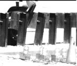

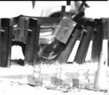

97 0.042 sec sec sec sec sec sec sec sec sec Figure 42. Additional Sequential Photographs, Test KC sec


98 84 Figure 43. Documentary Photographs, Test KC-1


99 85 Figure 44. Documentary Photographs, Test KC-1


100 86 Figure 45. Documentary Photographs, Test KC-1


101 Figure 46. Impact Location, Test KC-1 87


102 Figure 47. Vehicle Final Position and Trajectory Marks, Test KC-1 88


103 Figure 48. W-Beam Guardrail System Damage, Test KC-1 89


104 90 Figure 49. W-Beam Guardrail System Damage, Test KC-1


105 Figure 50. W-Beam Guardrail System Damage, Test KC-1 91


106 Figure 51. W-Beam Guardrail System Damage, Test KC-1 92


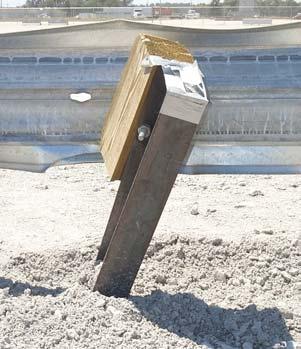
107 Figure 52. Post Nos. 18 and 19 Damage, Test KC-1 93


108 Figure 53. Post Nos.18 and 19 Damage, Test KC-1 94


109 Figure 54. Post Nos. 20 and 21 Damage, Test KC-1 95


110 Figure 55. Post Nos. 20 and 21 Damage, Test KC-1 96


111 Figure 56. Post Nos. 22 and 23 Damage, Test KC-1 97


112 Figure 57. Post Nos. 22 and 23 Damage, Test KC-1 98


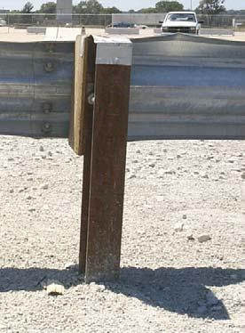
113 Figure 58. Post Nos. 24 and 25 Damage, Test KC-1 99


114 Figure 59. Post Nos. 24 and 25 Damage, Test KC-1 100


115 101 Figure 60. Culvert s Top Slab Damage, Test KC-1


116 Figure 61. Culvert s Top Slab Damage, Test KC-1 102

117 Figure 62. End Anchorage Permanent Set Deflection, Test KC-1 103


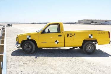
118 104 Figure 63. Vehicle Damage, Test KC-1


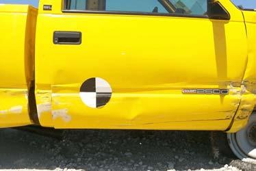

119 105 Figure 64. Vehicle s Right-Side Damage, Test KC-1


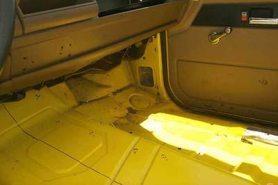
120 Figure 65. Occupant Compartment Deformations, Test KC-1 106
121 12 W-BEAM GUARDRAIL SYSTEM DESIGN DETAILS (OPTION NO. 2) The alternative installation of a guardrail system for use over a low-fill culvert was identical to the previous system except for the lateral placement of the steel posts with respect to the culvert s headwall. In option no. 1 (test KC-1), the back side of the steel posts were positioned 457 mm away from the front face of the culvert s headwall. For option no. 2, the back side of the steel posts were positioned only 25 mm away from the front face of the culvert s headwall. Additionally, option no. 2 used four individual ASTM A36 steel washer plates measuring 6.4-mm thick x 114-mm wide x 152-mm long, one at each bolt location of post nos. 18 through 20 and 22. Once again, the test installation consisted of m of standard 2.66-mm thick W-beam guardrail supported by steel posts, as shown in Figures 66 through 69. Also, anchorage systems similar to those used on tangent guardrail terminals were utilized on both the upstream and downstream ends of the guardrail system. Photographs of the test installation are shown in Figure 70 through
122 108 Figure 66. W-Beam Guardrail Attached to a Low-Fill Culvert (Option No. 2)
123 109 Figure 67. W-Beam Guardrail Attached to a Low-Fill Culvert Post Nos. 15 through 17, 21, and 23 through 27 (Option No. 2)
124 110 Figure 68. W-Beam Guardrail Attached to a Low-Fill Culvert Post Nos. 18 through 20 and 22 (Option No. 2)
125 111 Figure 69. W-Beam Guardrail Attached to a Low-Fill Culvert (Option No. 2)


126 Figure 70. W-Beam Guardrail Attached to a Low-Fill Culvert (Option No. 2) 112


127 113 Figure 71. Typical Posts for W-Beam Guardrail Attached to a Low-Fill Culvert (Option No.2)


128 Figure 72. Steel Washer Plate Connection Details on Bottom Side of Culvert s Top Slab 114


129 Figure 73. End Anchorage Systems 115
130 13 CRASH TEST NO. 2 (OPTION NO. 2) 13.1 Test KC-2 The 1,994-kg pickup truck impacted the W-beam guardrail at a speed of 99.7 km/hr and at an angle of 24.8 degrees. A summary of the test results and the sequential photographs are shown in Figure 74. Additional sequential photographs are shown in Figures 75 through 77. Documentary photographs of the crash test are shown in Figures 78 and Test Description Initial impact was to occur between post nos. 17 and 18 or 810-mm downstream from the center of post no. 17, as shown in Figure 80. Actual vehicle impact occurred 937-mm downstream from the center of post no. 17. At sec after impact, the right-front corner of the vehicle was at post no. 19. At sec, the right-front corner of the vehicle was at post no. 20 as post no. 19 continued to deflect backwards. At sec, the front of the vehicle was at post no. 21 as the rear end of the vehicle began to yaw toward the rail. At this same time, the right-front tire snagged on post no. 20 and caused the post to deflect downstream. Also, at this time, the guardrail released away from post no. 20, and the wooden blockout had rotated about the bolt. At sec, the top of the rail buckled between post nos. 22 and 23. At sec, the guardrail released away from post no. 21, and the wooden blockout released off of post no. 21. At sec, the right-front corner of the vehicle reached its maximum intrusion of 781 mm over the rail. At sec, the front of the vehicle was at post no. 22 as the vehicle began to redirect and roll CCW toward the rail. At sec, the right-rear corner of the vehicle was located over the rail near post no. 19 as it began to extend over the top of the rail. At sec, the vehicle s front-end pitched downward. At sec, the right-front corner of the vehicle was at post no. 24. At sec, the right-rear tire was 116
131 airborne. The vehicle became parallel to the guardrail at sec after impact with a resultant velocity of 69.4 km/hr. At sec, the right-rear tire appeared to have snagged on post no. 21 as the vehicle began to roll CCW toward the rail. At sec, the right-front corner of the vehicle lost contact with the system near post no. 25. At sec, the truck box reached its maximum intrusion of 741 mm over the rail. At sec, the vehicle reached its maximum yaw angle of 33.4 degrees. At sec, the vehicle showed significant CCW roll toward the rail. At this same time, the rightrear corner of the vehicle was at the midspan between post nos. 21 and 22. At sec after impact, the vehicle exited the guardrail at a trajectory angle of 11.8 degrees and at a resultant velocity of 68.0 km/hr. At this same time, the front of the vehicle continued to pitch downward as it rolled CCW toward the rail and reached its maximum roll angle of 7.5 degrees toward the rail. At sec, the right-front corner of the vehicle contacted the ground. At sec, the vehicle began to roll CW away from the rail as the right side of the front bumper remained in contact with the ground. At sec, the rear of the truck reached its maximum pitch angle of 7.7 degrees. At sec, the vehicle showed significant CW roll away from the rail. At sec, the vehicle had rolled onto its left side with the rear portion of the truck airborne. At sec, the vehicle had returned to an upright position after rolling completely over. The vehicle s post-impact trajectory is shown in Figures 74 and 81. The vehicle came to rest m downstream from impact and m laterally away from the traffic-side face of the rail, as shown in Figures 74 and Barrier Damage Damage to the barrier was moderate, as shown in Figures 82 through 89. Barrier damage consisted mostly of deformed W-beam, contact marks on a guardrail section, and deformed guardrail posts. 117
132 The guardrail damage consisted of moderate deformation and flattening of the lower portion of the impacted section of the W-beam rail between post nos. 17 and 23. Deformation and flattening of the upper portion of the impacted section of W-beam rail occurred between post nos. 17 and 24. Contact marks were found on the guardrail between post nos. 17 and 24. The bottom of the guardrail at post no. 19 deformed around the bottom of the wood blockout. The top of the guardrail was buckled at 152-mm downstream from the center of post no. 24. The W-beam was pulled off of post nos. 20 through 22. No significant guardrail damage occurred upstream of post no. 17 nor downstream of post no. 25. Steel post nos. 3 through 17 were twisted slightly. Steel post no. 18 rotated backward near the ground. Steel post nos. 19 through 22 were twisted and bent toward the ground. The traffic-side of steel post no. 19 was deformed 787 mm from the top, and the back side of this post was deformed against the concrete. Significant soil movement was observed around post no. 19. At post no. 19, severe concrete spalling was found on the headwall. Contact marks were found on the front face of post nos. 19 through 21. The wooden blockout at post nos. 20 through 23 remained attached to the posts but were rotated and damaged. No significant post damage or movement occurred to post nos. 23 through 41, and the blockouts at post nos. 3 through 19 and 24 through 39 remained undamaged. The upstream anchorage system was slightly moved longitudinally, while the downstream anchorage system remained unmoved. The posts in both the upstream and downstream anchorage systems were not damaged. The permanent set of the guardrail and posts is shown in Figures 82 through 88. The upstream cable anchor end encountered slight permanent set deformations, as shown in Figure 89. The maximum lateral permanent set rail and post deflections were approximately 279 mm at the 118
133 centerline of post no. 21 and 459 mm at post no. 20, as determined from the high-speed film analysis. The maximum lateral dynamic rail and post deflections were 473 mm at post no. 22, as determined from the high-speed film analysis Vehicle Damage Exterior vehicle damage was extensive, as shown in Figures 90 through 92. Minimal occupant compartment deformations occurred with only slight deformation of the forward floorpan area. Occupant compartment deformations and the corresponding locations are provided in Appendix H. Light contact marks were found along the lower portion of the entire right side of the vehicle. The front corner of the right-front fender was deformed downward and inward toward the engine compartment. The sheet metal at the joint between the lower-front portion of the right-side door and the right-front fender was sliced open and then crushed inward. The right-front side of the bumper was flattened and deformed inward. A buckling point was found at the center of the front bumper. The right-front steel rim was severely deformed, and the tire was removed from the steel rim. The front, rear, right-side, and left-side window glass as well as the sheet metal on the roof and the left-side fender and door were severely crushed during vehicle rollover. The rear of the vehicle and the right-rear, left-front, and left-rear tires and steel rims remained undamaged Occupant Risk Values The longitudinal and lateral occupant impact velocities were determined to be 5.90 m/sec and 5.10 m/sec, respectively. The maximum sec average occupant ridedown decelerations in the longitudinal and lateral directions were g s and g s, respectively. It is noted that the occupant impact velocities (OIV s) and occupant ridedown decelerations (ORD s) were within the suggested limits provided in NCHRP Report No The results of the occupant risk, 119
134 determined from the accelerometer data, are summarized in Figure 74. Results are shown graphically in Appendix I. The results from the rate transducer are shown graphically in Appendix J Discussion The analysis of the test results for test KC-2 showed that the W-beam guardrail attached to the concrete box culvert adequately contained the vehicle, but inadequately redirected the vehicle since the vehicle did not remain upright after collision with the W-beam guardrail system. There were no detached elements nor fragments which showed potential for penetrating the occupant compartment nor presented undue hazard to other traffic. Deformations of, or intrusion into, the occupant compartment that could have caused serious injury did not occur. After collision, the vehicle s trajectory revealed minimum intrusion into adjacent traffic lanes, but the roll over of the vehicle was unacceptable. In addition, the vehicle s exit angle was less than 60 percent of the impact angle. Therefore, test KC-2 conducted on the W-beam guardrail attached to the concrete box culvert was determined to be unacceptable according to the TL-3 safety performance criteria found in NCHRP Report No

... 140 mm x 190 mm by 1,080-mm long! Wood Spacer Blocks Post Nos. 2-39.")
... 68.0 km/hr Figure 74.")


135 0.000 sec sec sec sec sec! Test Number... KC-2! Date... 9/27/01! Appurtenance... W-beam guardrail with steel posts attached to culvert s top slab! Total Length m! Distance Between Posts and Headwall 25 mm! Steel W-Beam Thickness mm Top Mounting Height mm! Steel Posts Post Nos. 3-14, W152x13.4 by 1,829-mm long Post Nos W152x13.4 by 946-mm long! Wood Posts Post Nos. 1-2, (BCT) mm x 190 mm by 1,080-mm long! Wood Spacer Blocks Post Nos mm x 203 mm by 356-m long! Soil Type... Grading B - AASHTO M (1990)! Vehicle Model Chevrolet 2500 ¾-ton pickup Curb... 1,840 kg Test Inertial... 1,994 kg Gross Static... 1,994 kg! Vehicle Speed Impact km/hr Exit (resultant) km/hr Figure 74. Summary of Test Results and Sequential Photographs, Test KC-2! Vehicle Angle Impact deg Exit (trajectory) deg! Vehicle Snagging... Wheel snag on post no. 20! Vehicle Pocketing... None! Vehicle Stability... Vehicle rollover! Occupant Ridedown Deceleration (10 msec avg.) Longitudinal < 20 G s Lateral (not required) ! Occupant Impact Velocity Longitudinal < 12 m/s Lateral (not required) ! Vehicle Damage... Extensive TAD R&T-4 SAE RYAE9! Vehicle Stopping Distance m downstream 2.77 m traffic-side face! Barrier Damage... Moderate! Maximum Deflections Permanent Set mm Dynamic mm! Working Width mm 121


136 0.000 sec sec sec sec sec sec sec sec sec Figure 75. Additional Sequential Photographs, Test KC sec


137 0.000 sec sec sec sec sec sec sec sec Figure 76. Additional Sequential Photographs, Test KC-2 123


138 0.000 sec sec sec sec sec sec sec sec sec sec Figure 77. Additional Sequential Photographs, Test KC-2 124
139 Figure 78. Documentary Photographs, Test KC-2 125


140 Figure 79. Documentary Photographs, Test KC-2 126


141 Figure 80. Impact Location, Test KC-2 127


142 Figure 81. Final Vehicle Position and Trajectory Marks, Test KC-2 128


143 Figure 82. W-Beam Guardrail System Damage, Test KC-2 129


144 130 Figure 83. W-Beam Guardrail System Damage, Test KC-2


145 131 Figure 84. W-Beam Guardrail System Damage, Test KC-2


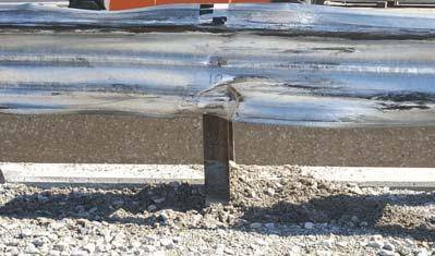
146 132 Figure 85. Post Nos. 18 and 19 Damage, Test KC-2


147 133 Figure 86. Post Nos. 20 and 21 Damage, Test KC-2


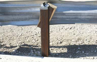
148 134 Figure 87. Post Nos. 22 and 23 Damage, Test KC-2


149 135 Figure 88. Post Nos. 24 and 25 Damage, Test KC-2


150 Figure 89. End Anchorage Permanent Set Deflections, Test KC-2 136


151 137 Figure 90. Vehicle Damage, Test KC-2


152 Figure 91. Vehicle Right-Front Corner Damage, Test KC-2 138


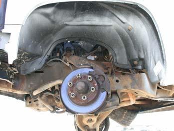

153 139 Figure 92. Undercarriage Vehicle Damage, Test KC-2
154 14 SUMMARY AND CONCLUSIONS Two W-beam guardrail systems for attachment to the top of a low-fill concrete culvert were designed, tested, and evaluated. The full-scale vehicle crash tests were performed according to the TL-3 criteria found in NCHRP Report No The first guardrail system (Option No. 1) was configured with W-beam rail supported by steel posts. Thirteen of the steel posts were attached to the concrete culvert s top slab with the back side of the posts placed 457 mm away from the front of the headwall. One full-scale vehicle crash test, KC-1, was performed on this guardrail system with a ¾-ton pickup truck and was determined to be acceptable according to the TL-3 safety performance criteria presented in NCHRP Report No From an analysis of the crash test results of KC-1, it should be noted that the bulk of the post motion occurred at the ground line of the impact and was found to be 254 mm. The second guardrail system (Option No. 2) was basically identical to the first system except for the placement of the steel posts attached to the culvert. For this design, the steel posts were spaced 25 mm away from the front of the culvert s headwall. Once again, one full-scale vehicle crash test, KC-2, was performed on this guardrail system with a ¾-ton pickup truck. During vehicle redirection, the pickup truck rolled over, and the test was determined to be unacceptable according to the TL-3 safety performance criteria presented in NCHRP Report No The vehicle s instability was attributed to the interaction of the vehicle s front tire and suspension with the steel post immediately beyond impact. The headwall of the culvert prevented the post from continuing to rotate backward, and subsequently caused a snag point for the vehicle s tire. A summary of the safety performance evaluation is provided in Table 6. A comparison of the accelerometer data for 140
155 tests KC-1 and KC-2 is shown in Appendix K. Similarly, a comparison of the rate transducer data for both tests is shown in Appendix L. Table 6. Summary of Safety Performance Evaluation Results Evaluation Factors Evaluation Criteria Test KC-1 Test KC-2 Structural Adequacy A. Test article should contain and redirect the vehicle; the vehicle should not penetrate, underride, or override the installation although controlled lateral deflection of the test article is acceptable. S S Occupant Risk D. Detached elements, fragments or other debris from the test article should not penetrate or show potential for penetrating the occupant compartment, or present an undue hazard to other traffic, pedestrians, or personnel in a work zone. Deformations of, or intrusions into, the occupant compartment that could cause serious injuries should not be permitted. S S F. The vehicle should remain upright during and after collision although moderate roll, pitching, and yawing are acceptable. S U K. After collision it is preferable that the vehicle's trajectory not intrude into adjacent traffic lanes. S U Vehicle Trajectory L. The occupant impact velocity in the longitudinal direction should not exceed 12 m/sec, and the occupant ridedown acceleration in the longitudinal direction should not exceed 20 G s. S S M. The exit angle from the test article preferably should be less than 60 percent of test impact angle measured at time of vehicle loss of contact with test device. M S S - Satisfactory M - Marginal U - Unsatisfactory NA - Not Available 141
156 15 RECOMMENDATIONS A strong-post, W-beam guardrail system for rigid attachment to the surface of low-fill concrete culverts was developed and successfully crash tested according to the criteria found in NCHRP Report No. 350 and is a suitable design for use on Federal-aid highways. The new guardrail system was configured with W152 x 13.4 steel posts spaced mm on center and with the back side positioned 457 mm away from the front of the culvert s headwall. From the results of tests KC-1 and KC-2, it was shown that a potential exists for vehicular instabilities or rollover to occur if the guardrail is placed too close to the culvert headwall. This phenomenon is the result of the system s posts being unable to rotate near the base due to contact with the top of the headwall, thus resulting in wheel snag on the posts, as seen in test KC-2. From an analysis of the KC-1 and KC-2 crash test results, it is recommended that the backside face of the steel posts can be positioned a minimum of 254 mm away from the front face of the culvert s headwall and still maintain acceptable barrier performance. However, any design modifications made to the guardrail system can only be verified through the use of full-scale crash testing. Finally, it should be noted that the W-beam guardrail system was configured with the entire length installed tangent. However, in actual field installations, this guardrail system can be installed with either one or two ends flared away from the traveled way. For locations where a guardrail flare will be used, the flare rates should follow the recommended guidelines provided in AASHTO s Roadside Design Guide (8). 142
157 16 REFERENCES 1. Polivka, K.A., Bielenberg, B.W., Sicking, D.L., Faller, R.K., and Rohde, J.R., Development of a 7.62-m Long Span Guardrail System, Final Report to the Midwest State s Regional Pooled Fund Program, Transportation Report No. TRP , Project No. SPR-3(017)- Year 7, Midwest Roadside Safety Facility, University of Nebraska-Lincoln, April 6, Polivka, K.A., Bielenberg, B.W., Sicking, D.L., Faller, R.K., Rohde, J.R., and Keller, E.A., Development of a 7.62-m Long Span Guardrail System Phase II, Final Report to the Midwest State s Regional Pooled Fund Program, Transportation Report No. TRP , Project No. SPR-3(017)-Year 9, Midwest Roadside Safety Facility, University of Nebraska- Lincoln, August 13, Faller, R.K., Sicking, D.L., Polivka, K.A., Rohde, J.R., and Bielenberg, R.W., A Long-Span Guardrail System for Culvert Applications, Transportation Research Record No. 1720, Transportation Research Board, National Research Council, Washington, D.C., Hirsch, T.J., and Beggs, D., Use of Guardrails on Low Fill Bridge Length Culverts, Transportation Research Record No. 1198, Transportation Research Board, National Research Council, Washington, D.C., Michie, J.D., Recommended Procedures for the Safety Performance Evaluation of Highway Appurtenances, National Cooperative Highway Research Program (NCHRP) Report No. 230, Transportation Research Board, Washington, D.C., March Pfeifer, B.G., and Luedke, J.K., Safety Performance Evaluation of a Nested W-Beam with Half-Post Spacing Over a Low-Fill Culvert, Final Report to the Kansas Department of Transportation, Transportation Report No. TRP , Midwest Roadside Safety Facility, University of Nebraska-Lincoln, March Ross, H.E., Sicking, D.L., Zimmer, R.A., and Michie, J.D., Recommended Procedures for the Safety Performance Evaluation of Highway Features, National Cooperative Research Program (NCHRP) Report No. 350, Transportation Research Board, Washington, D.C., Roadside Design Guide, Third Edition, American Association of State Highway and Transportation Officials (AASHTO), Washington, D.C., Memorandum on W-Beam Guardrail over Low-Fill Culverts, September 9, 1991, File Designation HNG-14, Federal Highway Administration (FHWA), Washington, D.C., Mak, K.K., Bligh, R.P., Gripne, D.J., and McDevitt, C.F., Long-Span Nested W-Beam Guardrails over Low-Fill Culverts, Transportation Research Record No. 1367, Transportation Research Board, National Research Council, Washington, D.C.,
158 11. Buth, C.E., Campise, W.L., Griffin, III, L.I., Love, M.L., and Sicking, D.L., Performance Limits of Longitudinal Barrier Systems - Volume I - Summary Report, Report No. FHWA/RD-86/153, Submitted to the Office of Safety and Traffic Operations, Federal Highway Administration, Performed by Texas Transportation Institute, May Ivy, D.L., Robertson, R., and Buth, C.E., Test and Evaluation of W-Beam and Thrie-Beam Guardrails, Report No. FHWA/RD-82/071, Submitted to the Office of Research, Federal Highway Administration, Performed by Texas Transportation Institute, March Ross, Jr., H.E., Perera, H.S., Sicking, D.L., and Bligh, R.P., Roadside Safety Design for Small Vehicles, National Cooperative Highway Research Program (NCHRP) Report No. 318, Transportation Research Board, Washington, D.C., May Hinch, J., Yang, T.L., and Owings, R., Guidance Systems for Vehicle Testing, ENSCO, Inc., Springfield, VA Standard Specifications for Transportation Materials and Methods of Sampling and Testing, American Association of State Highway and Transportation Officials (AASHTO), Part I Specifications, Seventeenth Edition, Washington, D.C., Powell, G.H., BARRIER VII: A Computer Program For Evaluation of Automobile Barrier Systems, Prepared for: Federal Highway Administration, Report No. FHWA RD-73-51, April Vehicle Damage Scale for Traffic Investigators, Second Edition, Technical Bulletin No. 1, Traffic Accident Data (TAD) Project, National Safety Council, Chicago, Illinois, Collision Deformation Classification - Recommended Practice J224 March 1980, Handbook Volume 4, Society of Automotive Engineers (SAE), Warrendale, Pennsylvania,
159 17 APPENDICES 145
160 APPENDIX A Bogie Vehicle Design and Fabrication Details Figure A-1. Bogie Vehicle Details Figure A-2. Bogie Vehicle Details Figure A-3. Bogie Vehicle Tube Fabrication Details Figure A-4. Bogie Vehicle Gusset Plate Details 146
161 147 Figure A-1. Bogie Vehicle Details
162 148 Figure A-2. Bogie Vehicle Details
163 149 Figure A-3. Bogie Vehicle Tube Fabrication Details
164 150 Figure A-4. Bogie Vehicle Gusset Plate Details
165 APPENDIX B Force-Deflection Behavior of Bogie Tests Figure B-1. Graph of Force-Deflection Behavior, Test KCB-1b Figure B-2. Graph of Force-Deflection Behavior, Test KCB-2 Figure B-3. Graph of Force-Deflection Behavior, Test KCB-3 Figure B-4. Graph of Force-Deflection Behavior, Test KCB-4 Figure B-5. Graph of Force-Deflection Behavior, Test KCB-5 Figure B-6. Graph of Force-Deflection Behavior, Test KCB-6 Figure B-7. Graph of Force-Deflection Behavior, Test KCB-7 151
166 152 Figure B-1. Graph of Force-Deflection Behavior, Test KCB-1b
167 153 Figure B-2. Graph of Force-Deflection Behavior, Test KCB-2
168 154 Figure B-3. Graph of Force-Deflection Behavior, Test KCB-3
169 155 Figure B-4. Graph of Force-Deflection Behavior, Test KCB-4
170 156 Figure B-5. Graph of Force-Deflection Behavior, Test KCB-5
171 157 Figure B-6. Graph of Force-Deflection Behavior, Test KCB-6
172 158 Figure B-7. Graph of Force-Deflection Behavior, Test KCB-7
173 APPENDIX C BARRIER VII Computer Models Figure C-1. Model of the Post-to-Culvert Guardrail System, Full-Post Spacing Figure C-2. Model of the Post-to-Culvert Guardrail System, Half-Post Spacing Figure C-3. Idealized Finite Element, 2 Dimensional Vehicle Model for the 1,996-kg Pickup Truck 159
174 160 Figure C-1. Model of the Post-to-Culvert Guardrail System, Full-Post Spacing
175 161 Figure C-2. Model of the Post-to-Culvert Guardrail System, Half-Post Spacing
176 162 Figure C-3. Idealized Finite Element, 2 Dimensional Vehicle Model for the 1,996-kg Pickup Truck
177 APPENDIX D Typical BARRIER VII Input File Note that the example BARRIER VII input data files included in Appendix D corresponds with examples of the standard post spacing and half-post spacing, respectively. 163
178 Kansas Guardrail on Culvert (Standard Post Spacing) - RUN No. 9B - NODE
179 Gauge W-Beam Gauge W-Beam Gauge W-Beam Gauge W-Beam Gauge W-Beam Gauge W-Beam Gauge W-Beam Gauge W-Beam Gauge W-Beam Gauge W-Beam Gauge W-Beam Gauge W-Beam Gauge W-Beam Gauge W-Beam Gauge W-Beam Gauge W-Beam Gauge W-Beam Gauge W-Beam Gauge W-Beam Gauge W-Beam Gauge W-Beam 165
180 Gauge W-Beam Gauge W-Beam Gauge W-Beam Simulated Strong Anchor Post Second BCT Post W6x9 by 6' Long W6x9 by 6' Long W6x9 by 6' Long W6x9 Posts on Culvert W6x9 Posts on Culvert W6x9 Posts on Culvert W6x9 Posts on Culvert W6x9 Posts on Culvert W6x9 Posts on Culvert W6x9 Posts on Culvert W6x9 Posts on Culvert W6x9 Posts on Culvert W6x9 Posts on Culvert (Removed)
181
182
183 Kansas Guardrail on Culvert (Half-Post Spacing) - RUN No. 9 - NODE
184 Gauge W-Beam Gauge W-Beam Gauge W-Beam Gauge W-Beam Gauge W-Beam Gauge W-Beam Gauge W-Beam Gauge W-Beam Gauge W-Beam Gauge W-Beam Gauge W-Beam Gauge W-Beam Gauge W-Beam Gauge W-Beam Gauge W-Beam Gauge W-Beam Gauge W-Beam Gauge W-Beam Gauge W-Beam Gauge W-Beam Gauge W-Beam 170
185 Gauge W-Beam Gauge W-Beam Gauge W-Beam Simulated Strong Anchor Post Second BCT Post W6x9 by 6' Long W6x9 by 6' Long W6x9 by 6' Long W6x9 Posts on Culvert W6x9 Posts on Culvert W6x9 Posts on Culvert W6x9 Posts on Culvert W6x9 Posts on Culvert W6x9 Posts on Culvert W6x9 Posts on Culvert W6x9 Posts on Culvert W6x9 Posts on Culvert W6x9 Posts on Culvert
186
187
188 APPENDIX E Occupant Compartment Deformation Data, Test KC-1 Figure E-1. Occupant Compartment Deformation Data, Test KC-1 174
189 Figure E-1. Occupant Compartment Deformation Data, Test KC-1 175
190 APPENDIX F Accelerometer Data Analysis, Test KC-1 Figure F-1. Graph of Longitudinal Deceleration, Test KC-1 Figure F-2. Graph of Longitudinal Occupant Impact Velocity, Test KC-1 Figure F-3. Graph of Longitudinal Occupant Displacement, Test KC-1 Figure F-4. Graph of Lateral Deceleration, Test KC-1 Figure F-5. Graph of Lateral Occupant Impact Velocity, Test KC-1 Figure F-6. Graph of Lateral Occupant Displacement, Test KC-1 176
191 177 Figure F-1. Graph of Longitudinal Deceleration Test KC-1
192 178 Figure F-2. Graph of Longitudinal Occupant Impact Velocity, Test KC-1
193 179 Figure F-3. Graph of Longitudinal Occupant Displacement, Test KC-1
194 180 Figure F-4. Graph of Lateral Deceleration, Test KC-1
195 181 Figure F-5. Graph of Lateral Occupant Impact Velocity, Test KC-1
196 182 Figure F-6. Graph of Lateral Occupant Displacement, Test KC-1
197 APPENDIX G Rate Transducer Data Analysis, Test KC-1 Figure G-1. Graph of Roll, Pitch, and Yaw Angular Displacements, Test KC-1 183
198 184 Figure G-1. Graph of Roll, Pitch, and Yaw Angular Displacements, Test KC-1
199 APPENDIX H Occupant Compartment Deformation Data, Test KC-2 Figure H-1. Occupant Compartment Deformation Data, Test KC-2 185

200 Figure H-1. Occupant Compartment Deformation Data, Test KC-2 186
Road Side Design: When is a Barrier Required?
 Road Side Design: When is a Barrier Required? Jennifer Schmidt, Ph.D., P.E. University of Nebraska-Lincoln Department of Civil Engineering Guide Rail Safety Symposium Brampton, ON October 24, 2017 Research
Racetrack SAFER barrier on temporary concrete barriers
 University of Nebraska - Lincoln DigitalCommons@University of Nebraska - Lincoln Civil Engineering Faculty Publications Civil Engineering 2013 Racetrack SAFER barrier on temporary concrete barriers John
Use of Throw Distances of Pedestrians and Bicyclists as Part of a Scientific Accident Reconstruction Method 1
 contents Introduction xi CHAPTER 1 Use of Throw Distances of Pedestrians and Bicyclists as Part of a Scientific Accident Reconstruction Method 1 Introduction 2 Basis of Speed Calculation 2 New Results
DEVELOPMENT OF A RETROFIT, LOW- DEFLECTION TEMPORARY CONCRETE BARRIER SYSTEM
 Duplication for publication or sale is strictly prohibited without prior written permission of the Transportation Research Board Paper No. 16-1596 DEVELOPMENT OF A RETROFIT, LOW- DEFLECTION TEMPORARY CONCRETE
DISTRIBUTION: Electronic Recipients List TRANSMITTAL LETTER NO. (13-01) MINNESOTA DEPARTMENT OF TRANSPORTATION. MANUAL: Road Design English Manual
 MINNESOTA DEPARTMENT OF TRANSPORTATION. MANUAL: Road Design English Manual") DISTRIBUTION: Electronic Recipients List MINNESOTA DEPARTMENT OF TRANSPORTATION DEVELOPED BY: Design Standards Unit ISSUED BY: Office of Project Management and Technical Support TRANSMITTAL LETTER NO.
DISTRIBUTION: Electronic Recipients List MINNESOTA DEPARTMENT OF TRANSPORTATION DEVELOPED BY: Design Standards Unit ISSUED BY: Office of Project Management and Technical Support TRANSMITTAL LETTER NO.
PLACEMENT OF SIGNS RECOMMENDED PRACTICES SUB-SECTION
 Page 1 of 6 RECOMMENDED PRACTICES PART SECTION SUB-SECTION HIGHWAY SIGNS GENERAL General Proper positioning of signs is an important element in the overall control of traffic within a roadway network.
PHASE 1 WIND STUDIES REPORT
 PHASE 1 WIND STUDIES REPORT ENVIRONMENTAL STUDIES AND PRELIMINARY DESIGN FOR A SUICIDE DETERRENT SYSTEM Contract 2006-B-17 24 MAY 2007 Golden Gate Bridge Highway and Transportation District Introduction
Reconstructing a rollover includes examining physical evidence on the roadway and the vehicle. Here s a detailed roadmap to examining that evidence
 Roadway and vehicle evidence in rollover collisions Reconstructing a rollover includes examining physical evidence on the roadway and the vehicle. Here s a detailed roadmap to examining that evidence BY
H8 Signs, Supports and Poles
 Alberta Infrastructure and Transportation Roadside Design Guide November 2007 H8 Signs, Supports and Poles H8.1 Introduction This section identifies the appropriate roadside safety treatment for signs,
Item 404 Driving Piling
 Item Driving Piling 1. DESCRIPTION Drive piling. 2. EQUIPMENT 2.1. Driving Equipment. Use power hammers for driving piling with specified bearing resistance. Use power hammers that comply with Table 1.
State of Nevada Department of Transportation Materials Division
 State of Nevada Department of Transportation Materials Division METHOD OF TEST FOR EVALUATION OF PAVEMENT RIDE QUALITY USING INERTIAL PROFILING SYSTEMS SCOPE This test method describes the procedure used
EUROPEAN NEW CAR ASSESSMENT PROGRAMME (Euro NCAP) SLED TEST PROCEDURE FOR ASSESSING KNEE IMPACT AREAS
 SLED TEST PROCEDURE FOR ASSESSING KNEE IMPACT AREAS") www.euroncap.com EUROPEAN NEW CAR ASSESSMENT PROGRAMME (Euro NCAP) SLED TEST PROCEDURE FOR ASSESSING KNEE IMPACT AREAS Version 1.0a December 2004 Sled Test Procedure for Assessing Knee Impact Areas (V1.0a)
www.euroncap.com EUROPEAN NEW CAR ASSESSMENT PROGRAMME (Euro NCAP) SLED TEST PROCEDURE FOR ASSESSING KNEE IMPACT AREAS Version 1.0a December 2004 Sled Test Procedure for Assessing Knee Impact Areas (V1.0a)
Study of the Effects of Buried Pipe Integrity on Roadway Subsidence
 Pipe-RU6558 Study of the Effects of Buried Pipe Integrity on Roadway Subsidence FINAL REPORT October 2005 Submitted by Dr. Husam Najm * Professor Dr. Ali Maher * Professor/Director Dr. Nenad Gucunski *
TRAFFIC CONTROL DEVICES
 TRAFFIC CONTROL DEVICES SIGNS Temporary traffic control work zone signs include regulatory, warning and guide signs utilized to provide regulations, warnings and guidance information to road users impacted
EUROPEAN NEW CAR ASSESSMENT PROGRAMME (Euro NCAP) SLED TEST PROCEDURE FOR ASSESSING KNEE IMPACT AREAS. For 2020 implementation
 SLED TEST PROCEDURE FOR ASSESSING KNEE IMPACT AREAS. For 2020 implementation") EUROPEAN NEW CAR ASSESSMENT PROGRAMME (Euro NCAP) SLED TEST PROCEDURE FOR ASSESSING KNEE IMPACT AREAS For 2020 implementation Copyright Euro NCAP 2018 - This work is the intellectual property of Euro NCAP.
EUROPEAN NEW CAR ASSESSMENT PROGRAMME (Euro NCAP) SLED TEST PROCEDURE FOR ASSESSING KNEE IMPACT AREAS For 2020 implementation Copyright Euro NCAP 2018 - This work is the intellectual property of Euro NCAP.
Specifications for Synchronized Sensor Pipe Condition Assessment (AS PROVIDED BY REDZONE ROBOTICS)
") Specifications for Synchronized Sensor Pipe Condition Assessment (AS PROVIDED BY REDZONE ROBOTICS) A. Scope of Work The work covered by these specifications consists of furnishing all materials, labor,
Specifications for Synchronized Sensor Pipe Condition Assessment (AS PROVIDED BY REDZONE ROBOTICS) A. Scope of Work The work covered by these specifications consists of furnishing all materials, labor,
Fall Protection Resource Guide P AGE 1
 Fall Protection Resource Guide P AGE 1 As a Home Builder, we do not self-perform any work. This section is a resource guide only and is not intended to put any requirements on the company. All subcontractors,
FALL PROTECTION GUIDELINE
 FALL PROTECTION GUIDELINE July 2001 Table of Contents INTRODUCTION...3 CONTROL MEASURES...4 SURFACE PROTECTION...4 FIXED BARRIERS...5 EXAMPLES OF GUARDRAIL...6 WARNING BARRIERS...7 HANDRAILS...8 SURFACE
29 CFR 1926, Subpart M. Fall Protection Program Table of Contents
 I. Objective II. Policy III. Assignment of Responsibility IV. Training V. Controlled Access Zones VI. Excavations VII. Fall Protection Systems A. Covers B. Guardrail Systems C. Personal Fall Arrest Systems
FAIRWAY PALMS II CONDOMINIUM PROPERTY
 FAIRWAY PALMS II CONDOMINIUM PROPERTY 6533, through 6553 SE Federal HWY, Stuart Florida, 34997. Structural Inspection Report Prepared by CA 26583 Ph: 561-204-5000 Fax: 561-204-1050 E-mail: aali@universalengineering.net
DEFINITIONS Activity Area - Advance Warning Area Advance Warning Sign Spacing Advisory Speed Approach Sight Distance Attended Work Space
 DEFINITIONS Activity Area - that part of a TTC zone activity area where the work actually takes place. It consists of the work space, traffic space and one or more buffer spaces. Advance Warning Area -
ENTUCKY RANSPORTATION C ENTER. College of Engineering
 Research Report KTC-05-34/SPR-297-05-1I T K ENTUCKY RANSPORTATION C ENTER College of Engineering USE OF ULTRA-LIGHTWEIGHT GEOFOAM TO REDUCE STRESSES IN HIGHWAY CULVERT EXTENSIONS Our Mission We provide
RURAL HIGHWAY SHOULDERS THAT ACCOMMODATE BICYCLE AND PEDESTRIAN USE (TxDOT Project ) June 7, Presented by: Karen Dixon, Ph.D., P.E.
 June 7, Presented by: Karen Dixon, Ph.D., P.E.") RURAL HIGHWAY SHOULDERS THAT ACCOMMODATE BICYCLE AND PEDESTRIAN USE (TxDOT Project 0-6840) June 7, 2016 Presented by: Karen Dixon, Ph.D., P.E., TTI Team: Kay Fitzpatrick, Raul Avelar, & Subasish Das Project
RURAL HIGHWAY SHOULDERS THAT ACCOMMODATE BICYCLE AND PEDESTRIAN USE (TxDOT Project 0-6840) June 7, 2016 Presented by: Karen Dixon, Ph.D., P.E., TTI Team: Kay Fitzpatrick, Raul Avelar, & Subasish Das Project
Non-Linear Seismic Analysis of Multi-Storey Building
 Non-Linear Seismic Analysis of Multi-Storey Building Uzair Khan 1 1 M.Tech (Structural & Construction Engineering) Department of Civil Engineering, National Institute of Technology, Jalandhar. Hina Gupta
STUDY PROCESS & SCHEDULE
 STUDY PROCESS & SCHEDULE Route Centennial Bridge Study KDOT Project No. -52 KA-3229-01 STUDY OVERVIEW STUDY SCHEDULE The Kansas Department of Transportation (KDOT) has identified a future need to replace
GUIDELINES FOR USING DECISION SIGHT DISTANCE AT IGNALIZED INTERSECTIONS NEAR VERTICAL CURVES
 1. Report No. FHWA/TX-05/0-4084-P2 4. Title and Subtitle 2. Government Accession No. 3. Recipient's Catalog No. GUIDELINES FOR USING DECISION SIGHT DISTANCE AT IGNALIZED INTERSECTIONS NEAR VERTICAL CURVES
Crash Analysis of I-64 Closure in St. Louis County
 Report # MATC-MST: 341 Final Report 25-1121-0001-341 Crash Analysis of I-64 Closure in St. Louis County Ghulam H. Bham, Ph.D. Professor Department of Civil, Architectural, and Environmental Engineering
Roadway Design Manual
 Roadway Design Manual Manual Notice Archive by Texas Department of Transportation (512) 302-2453 all rights reserved Manual Notice 2009-1 From: Manual: Mark A. Marek, P.E Roadway Design Manual Effective
SIMON Simulation of Non-Automotive Vehicle Free Rolling Response
 SIMON Simulation of Non-Automotive Vehicle Free Rolling Response Ciro Ramirez, PhD, PE, CSHO, C. L. Long, Jr., P.E., and R. Joe Thornhill, PhD, PE, CSHO Thornhill, Ramirez & Associates, Inc. Copyright
ANNUAL INSPECTION BY A QUALIFIED PROFESSIONAL ENGINEER ALL CCR IMPOUNDMENTS CCR Rule Section (b)
") ANNUAL INSPECTION BY A QUALIFIED PROFESSIONAL ENGINEER ALL CCR IMPOUNDMENTS ASBURY POWER PLANT 21133 Uphill Lane Asbury, Missouri 64832 January 18, 2017 EMPIRE DISTRICT ELECTRIC COMPANY Prepared by: Rachel
ANNUAL INSPECTION BY A QUALIFIED PROFESSIONAL ENGINEER ALL CCR IMPOUNDMENTS ASBURY POWER PLANT 21133 Uphill Lane Asbury, Missouri 64832 January 18, 2017 EMPIRE DISTRICT ELECTRIC COMPANY Prepared by: Rachel
The Use of BS 5400: Part 10: Code of Practice for Fatigue
 THE HIGHWAYS AGENCY THE SCOTTISH OFFICE DEVELOPMENT DEPARTMENT Amendment No. 1, dated November 1983 THE WELSH OFFICE Y SWYDDFA GYMREIG THE DEPARTMENT OF THE ENVIRONMENT FOR NORTHERN IRELAND The Use of
Issues Relating to the Geometric Design of Intersections Vergil G. Stover
 Introduction Issues Relating to the Geometric Design of Intersections Vergil G. Stover This paper presents five issues, or topics, that the author suggests be addressed in the design of intersections.
GUARDRAIL NEED FOR EMBANKMENTS AND CULVERTS
 NDOR Research Project Number SPR-PL-1(31) P478 Transportation Research Studies GUARDRAIL NEED FOR EMBANKMENTS AND CULVERTS Daniel F. Wolford and Dean L. Sicking F I N A L R E P O R T Department of Civil
Technical Memorandum. Subject: Interchange Ramp Terminal Configuration. Expiration. Implementation. Introduction
 Minnesota Department of Transportation Engineering Services Division Technical Memorandum To: Electronic Distribution Recipients From: Nancy T. Daubenberger, P.E. Assistant Commisioner, Engineering Services
Road Safety Facilities Implemented in Japan
 Road Safety Facilities Implemented in Japan 1 Road Safety Facilities 1.Guard Fence 2.Road Lighting 3.Other Road Safety Facilities 2 Road Safety Facilities 1.Guard Fence 2.Road Lighting 3.Other Road Safety
UNDERWATER BRIDGE INSPECTION REPORT DISTRICT 8 - LAC QUI PARLE COUNTY
 UNDERWATER BRIDGE INSPECTION REPORT STRUCTURE NO. 6391 CSAH NO. 33 OVER THE MINNESOTA RIVER DISTRICT 8 - LAC QUI PARLE COUNTY OCTOBER 22, 2012 PREPARED FOR THE MINNESOTA DEPARTMENT OF TRANSPORTATION BY
Driveway Design Criteria
 Design Manual Chapter 5 - Roadway Design 5L - Access Management 5L-4 Driveway Design Criteria A. General For efficient and safe operations, access drives and minor public street intersections can be improved
SOIL-STRUCTURE INTERACTION ANALYSIS OF THE MANHATTAN BRIDGE FOUNDATIONS
 10NCEE Tenth U.S. National Conference on Earthquake Engineering Frontiers of Earthquake Engineering July 21-25, 2014 Anchorage, Alaska SOIL-STRUCTURE INTERACTION ANALYSIS OF THE MANHATTAN BRIDGE FOUNDATIONS
Acoustical Modeling of Reciprocating Compressors With Stepless Valve Unloaders
 Acoustical Modeling of Reciprocating Compressors With Stepless Valve Unloaders Kelly Eberle, P.Eng. Principal Engineer keberle@betamachinery.com Brian C. Howes, M.Sc., P.Eng. Chief Engineer bhowes@betamachinery.com
THE USE OF SPIN FIN PILES IN MASSACHUSETTS
 THE USE OF SPIN FIN PILES IN MASSACHUSETTS Les R. Chernauskas, P.E., Geosciences Testing and Research, Inc., North Chelmsford, MA Leo J. Hart, Geosciences Testing and Research, Inc., North Chelmsford,
TRAVSMART permanent single-cable horizontal lifeline system
 The Travsmart single-line system provides a smooth travel. It allows the traveler to move freely over the intermediate anchors, minimizing wear and eliminating user assistance. The user s hands remain
UNDERWATER BRIDGE INSPECTION REPORT DISTRICT 8 - LAC QUI PARLE COUNTY
 UNDERWATER BRIDGE INSPECTION REPORT STRUCTURE NO. 6391 CSAH NO. 33 OVER THE MINNESOTA RIVER DISTRICT 8 - LAC QUI PARLE COUNTY PREPARED FOR THE MINNESOTA DEPARTMENT OF TRANSPORTATION BY COLLINS ENGINEERS,
UNDERWATER BRIDGE INSPECTION REPORT DISTRICT 4 - OTTER TAIL COUNTY
 UNDERWATER BRIDGE INSPECTION REPORT STRUCTURE NO. L0885 TWP NO. 970 OVER THE OTTER TAIL RIVER DISTRICT 4 - OTTER TAIL COUNTY PREPARED FOR THE MINNESOTA DEPARTMENT OF TRANSPORTATION BY COLLINS ENGINEERS,
Access Management Standards
 Access Management Standards Section 1: Application of Access Standards This chapter describes the Department's access management standards for access connections on the county roadway system. The standards
ICE LOADS MONITORING SYSTEMS
 Guide for Ice Loads Monitoring Systems GUIDE FOR ICE LOADS MONITORING SYSTEMS MAY 2011 American Bureau of Shipping Incorporated by Act of Legislature of the State of New York 1862 Copyright 2011 American
Greenup Lock Filling and Emptying System Study
 Fourth LACCEI International Latin American and Caribbean Conference for Engineering and Technology (LACCET 2006) Breaking Frontiers and Barriers in Engineering: Education, Research and Practice 21-23 June
Texas Transportation Institute The Texas A&M University System College Station, Texas
 1. Report No. FHWA/TX-05/0-4084-P1 4. Title and Subtitle GUIDELINES FOR THE USE OF COUNTERMEASURES TO REDUCE CRASHES ON APPROACHES TO SIGNALIZED INTERSECTIONS NEAR VERTICAL CURVES 2. Government Accession
SECTION 1A NEW JERSEY TURNPIKE GEOMETRIC DESIGN
 SECTION 1A NEW JERSEY TURNPIKE GEOMETRIC DESIGN Table of Contents Page No 1A.1 GENERAL...1 1A.1.1 DESIGN CONTROLS...1 1A.2 MAINLINE ROADWAYS...4 1A.2.1 ROADWAY DESIGNATION...4 1A.2.2 DESIGN SPEED...4 1A.2.3
Sponsored by the Office of Traffic and Safety of the Iowa Department of Transportation NOVEMBER 2001 CTRE
 PAVED SHOULDERS ON PRIMARY HIGHWAYS IN IOWA: AN ANALYSIS OF SHOULDER SURFACING CRITERIA, COSTS, AND BENEFITS EXECUTIVE SUMMARY Sponsored by the Office of Traffic and Safety of the Iowa Department of Transportation
APPENDIX J HYDROLOGY AND WATER QUALITY
 APPENDIX J HYDROLOGY AND WATER QUALITY J-1 Technical Report on Airport Drainage, Northern Sector Airport and Ordinance Creek Watershed / Preliminary Creek Constructed Natural Channel Culvert J-2 Preliminary
GENERAL. 1. Description
 GENERAL 1. Description This standard identifies minimum requirements that shall be met for all Bus Stops in the design and construction of elements for Arlington County Horizontal Design Standards. This
Work Zone Traffic Safety
 Work Zone Traffic Safety Summary The Hazard: death or serious injury from being struck by vehicles or equipment in work zones. Who is at risk: streets/highways, utilities and other public works department
Evaluating the Design Safety of Highway Structural Supports
 Evaluating the Design Safety of Highway Structural Supports by Fouad H. Fouad and Elizabeth A. Calvert Department of Civil and Environmental Engineering The University of Alabama at Birmingham Birmingham,
DYNAMIC CRUSH TEST ON HYDROGEN PRESSURIZED CYLINDER
 DYNAMIC CRUSH TEST ON HYDROGEN PRESSURIZED CYLINDER Hiroyuki Mitsuishi 1, Koichi Oshino 2, Shogo Watanabe 2 1 Japan Automobile Research Institute, Takaheta1328-23, Shirosato, Ibaraki, 311-4316, Japan 2
Appendix T CCMP TRAIL TRAFFIC & TRANSPORTATION DESIGN STANDARD
 Appendix T CCMP 3.3.4 TRAIL TRAFFIC & TRANSPORTATION DESIGN STANDARD 3.3.4 Trail Traffic and Transportation Design Multi-use trails have certain design standards, which vary depending on the agency that
UNDERWATER BRIDGE INSPECTION REPORT STRUCTURE NO CSAH 133 OVER A DITCH ST. LOUIS COUNTY
 UNDERWATER BRIDGE INSPECTION REPORT STRUCTURE NO. 7780 CSAH 133 OVER A DITCH ST. LOUIS COUNTY SEPTEMBER 27, 2012 PREPARED FOR THE MINNESOTA DEPARTMENT OF TRANSPORTATION BY COLLINS ENGINEERS, INC. JOB NO.
Evaluation of M-99 (Broad Street) Road Diet and Intersection Operational Investigation
 Road Diet and Intersection Operational Investigation") Evaluation of M-99 (Broad Street) Road Diet and Intersection Operational Investigation City of Hillsdale, Hillsdale County, Michigan June 16, 2016 Final Report Prepared for City of Hillsdale 97 North Broad
Evaluation of M-99 (Broad Street) Road Diet and Intersection Operational Investigation City of Hillsdale, Hillsdale County, Michigan June 16, 2016 Final Report Prepared for City of Hillsdale 97 North Broad
TECHNICAL MANUAL. COPRA Anchoring Coupler. For Smart Bolted Connections
 TECHNICAL MANUAL Anchoring Coupler For Smart Bolted Connections Version: PEIKKO GROUP 03/2017 Anchoring Coupler For bolted connections Multi-purpose anchoring system for all bolted connections Simplifi
Subject: Use of Pull-off Areas in Work Zones Page: 1 of 13. Brief Description: Guidance for the use and placement of pull-off area in work zones.
 6 - G2 Subject: Use of Pull-off Areas in Work Zones Page: 1 of 13 MdMUTCD REF. NO. None Date Issued: 09/09 Effective Date: 09/09 Brief Description: Guidance for the use and placement of pull-off area in
Developed by: The American Traffic Safety Services Association (ATSSA) 15 Riverside Parkway, Suite 100 Fredericksburg, VA
 15 Riverside Parkway, Suite 100 Fredericksburg, VA") Addendum Developed by: The American Traffic Safety Services Association (ATSSA) 15 Riverside Parkway, Suite 100 Fredericksburg, VA 22406-1022 800-272-8772 This material is based upon work supported by
Addendum Developed by: The American Traffic Safety Services Association (ATSSA) 15 Riverside Parkway, Suite 100 Fredericksburg, VA 22406-1022 800-272-8772 This material is based upon work supported by
Strategic Research PROGRAM FOLLOW-UP ASSESSMENT OF THE MOBILEYE SHIELD+ COLLISION AVOIDANCE SYSTEM
 165610-1 Strategic Research PROGRAM FOLLOW-UP ASSESSMENT OF THE MOBILEYE SHIELD+ COLLISION AVOIDANCE SYSTEM March 2017 1. Report No. TTI/SRP/17/165610-1 2. Government Accession No. 3. Recipient's Catalog
Kentucky Transportation Center
 Kentucky Transportation Center TECHNICAL ASSISTANCE REPORT Forensic Pavement Evaluation for US 31 W, Jefferson County, Kentucky KTC TA-15 02/KH91 14 1F DOI: http://dx.doi.org/10.13023/ktc.ta.2015.02 Author(s):
3-13 UFC - GENERAL PROVISIONS AND GEOMETRIC DESIGN FOR ROADS, STREETS, WALKS, AND OPEN
 maintenance, and erosion. Stability is required to maintain the integrity of the pavement structure, and a slope stability analysis should be conducted for cuts and fills greater than 15 feet. For lower
Cover Page for Lab Report Group Portion. Head Losses in Pipes
 Cover Page for Lab Report Group Portion Head Losses in Pipes Prepared by Professor J. M. Cimbala, Penn State University Latest revision: 02 February 2012 Name 1: Name 2: Name 3: [Name 4: ] Date: Section
Chapter Twenty-eight SIGHT DISTANCE BUREAU OF LOCAL ROADS AND STREETS MANUAL
 Chapter Twenty-eight SIGHT DISTANCE BUREAU OF LOCAL ROADS AND STREETS MANUAL Jan 2006 SIGHT DISTANCE 28(i) Chapter Twenty-eight SIGHT DISTANCE Table of Contents Section Page 28-1 STOPPING SIGHT DISTANCE
NOT TO SCALE PUBLIC WORKS STANDARD DETAILS CURB DETAILS DATE: MARCH 2013 FILE NAME: CURB.DWG
 NOT TO SCALE PUBLIC WORKS STANDARD DETAILS CURB DETAILS DATE: MARCH 2013 FILE NAME: CURB.DWG NOT TO SCALE PUBLIC WORKS STANDARD DETAILS SIDEWALK RAMPS DATE: MARCH 2013 FILE NAME: SIDEWALK RAMPS.DWG NOT
INVESTIGATION OF THE ******* BICYLE CRASH
 INVESTIGATION OF THE ******* BICYLE CRASH By: Lance E. Robson, P.E. April 16, 2010 INVESTIGATION OF THE ******* BICYLE CRASH ENGINEER'S REPORT April 16, 2010 1. INTRODUCTION This bicycle crash occurred
APPLICATION OF PUSHOVER ANALYSIS ON EARTHQUAKE RESPONSE PREDICATION OF COMPLEX LARGE-SPAN STEEL STRUCTURES
 APPLICATION OF PUSHOVER ANALYSIS ON EARTHQUAKE RESPONSE PREDICATION OF COMPLEX LARGE-SPAN STEEL STRUCTURES J.R. Qian 1 W.J. Zhang 2 and X.D. Ji 3 1 Professor, 3 Postgraduate Student, Key Laboratory for
Evaluation of the Wisconsin DOT Walking Profiler
 Final Report Evaluation of the Wisconsin DOT Walking Profiler March 2007 U.S. Department of Transportation Federal Highway Administration Notice This document is disseminated under the sponsorship of the
New in the MUTCD: The Flashing Yellow Arrow Presented at the 57 th Annual Traffic and Safety Conference May 17, 2006
 New in the MUTCD: The Flashing Yellow Arrow Presented at the 57 th Annual Traffic and Safety Conference May 17, 2006 David A. Noyce, Ph.D., P.E. University of Wisconsin - Madison The FYA Story Research
AF100. Subsonic Wind Tunnel AERODYNAMICS. Open-circuit subsonic wind tunnel for a wide range of investigations into aerodynamics
 Open-circuit subsonic wind tunnel for a wide range of investigations into aerodynamics Page 1 of 4 Works with Computer, chair and work table shown for photographic purposes only (not included) Screenshot
Illini Union Champaign, IL. February 24, Paul Lorton, P.E. Safety Programs Unit Chief IDOT, Division of Highways, Bureau of Safety Engineering
 Illini Union Champaign, IL February 24, 2015 Paul Lorton, P.E. Safety Programs Unit Chief IDOT, Division of Highways, Bureau of Safety Engineering Temporary Concrete Barrier Pinning and Drop-off Policy
WIND-INDUCED LOADS OVER DOUBLE CANTILEVER BRIDGES UNDER CONSTRUCTION
 WIND-INDUCED LOADS OVER DOUBLE CANTILEVER BRIDGES UNDER CONSTRUCTION S. Pindado, J. Meseguer, J. M. Perales, A. Sanz-Andres and A. Martinez Key words: Wind loads, bridge construction, yawing moment. Abstract.
Fall Protection Checklist. Guardrail System
 Fall Protection Checklist Location/Department: Date of Inspection: Inspectors: Corrective Actions: Work order/memos were issued: Yes No Date issued: In accordance with the MIOSHA and OSHA standards the
Traffic Signal Redesign 50% Design Report
 Traffic Signal Redesign 50% Design Report Joseph Davis, Jace Elkins, Jordan Weyrauch and Zach Crimmins CENE 486 Capstone J3Z Engineering March 10 th, 2016 Table of Contents 1.0 Project Description...1
THE FUTURE OF THE TxDOT ROADWAY DESIGN MANUAL
 THE FUTURE OF THE TXDOT ROADWAY DESIGN MANUAL Kenneth Mora, P.E. (Design Division) 10/10/2017 Table of contents 1 2 Reduction in FHWA design controlling criteria Innovative Intersection Guidance 3-7 8-42
RELIABILITY ASSESSMENT, STATIC AND DYNAMIC RESPONSE OF TRANSMISSION LINE TOWER: A COMPARATIVE STUDY
 RELIABILITY ASSESSMENT, STATIC AND DYNAMIC RESPONSE OF TRANSMISSION LINE TOWER: A COMPARATIVE STUDY Yusuf Mansur Hashim M. Tech (Structural Engineering) Student, Sharda University, Greater Noida, (India)
Quality Standards. Methods to determine whether the various. Marginal, or or Unacceptable. mndot.gov/fieldmanual. Standards.
 Quality Standards Methods to determine whether the various traffic traffic control control devices devices are Acceptable, are Acceptable,,, or or Unacceptable. Quality Standards mndot.gov/fieldmanual
Quality. Standards. Methods to determine whether the various traffic control devices are Acceptable, Marginal, or Unacceptable.
 Quality Standards Quality Standards Methods to determine whether the various traffic control devices are Acceptable,, or Unacceptable. Contents Introduction.................................................6K-91
7 DESIGN CRITER RIA 7.1 Design Space Requirements
 7 DESIGN CRITERIA 7.1 Design Space Requirements The Nebraskaa Department of Roads (NDOR) provided examples of intersections where an approved guardrail end terminal and Approach Guardrail Transition (AGT)
OLD GI PART 3, FIXED LADDERS COMPARISON TO NEW RULES
 This table compares the rescinded rules for fixed ladders from old GI Part 3 with the new rules for fixed ladders in GI Part 2, Walking-Working Surfaces. The first column contains the rescinded rule (struckthrough).
Roundabout Design Aid PREPARED BY TRAFFIC AND SAFETY
 Roundabout Design Aid PREPARED BY TRAFFIC AND SAFETY May 2018 Engineering Manual Preamble This manual provides guidance to administrative, engineering, and technical staff. Engineering practice requires
GEA FOR ADVANCED STRUCTURAL DYNAMIC ANALYSIS
 SMART SOLUTIONS FOR VIBRATION MONITORING GEA FOR ADVANCED STRUCTURAL DYNAMIC ANALYSIS ANALYSIS OF CIVIL STRUCTURES - EXPO MERLATA PEDESTRIAN BRIDGE ABSTRACT Civil structures and in particular bridges and
INDEX. Geometric Design Guide for Canadian Roads INDEX
 Acceleration lane, see Lanes, Acceleration Access, 8.1 Access Management and Functional Classification 8.2 Access Management by Design Classification 8.3 Access Configuration 8.4 Building Set-Back Guidelines
Downloaded from Downloaded from /1
 VI SEMESTER FINAL EXAMINATION-2003 Q. [1] [a] Draw a right angle four-arm intersection of two roads and show various conflicts points if [a] both roads are with way movements, and [b] one road is with
Root Cause Determination of Excessive Hull Vibration On a First-In-Class Tugboat Design By Wylie Moreshead, P.E., Azima DLI
 Root Cause Determination of Excessive Hull Vibration On a First-In-Class Tugboat Design By Wylie Moreshead, P.E., Azima DLI In August of 2002, Azima DLI was tasked to collect vibration data on a new tug
Real-Time Smoothness Measurements on Concrete Pavements During Construction
 Recommended Practice for Real-Time Smoothness Measurements on Concrete Pavements During Construction XX-## (2017) 1. SCOPE 1.1. This document provides language that can be used by an Owner-Agency to develop
Fall Protection. 29 CFR Appendix C 29 CFR 1926 Subpart M
 Fall Protection 29 CFR 1910.66 Appendix C 29 CFR 1926 Subpart M Duty to Have Fall Protection Provide fall protection systems which meet the criteria of 1926 and 1910 Make fall protection an integral part
UNDERWATER BRIDGE INSPECTION REPORT DISTRICT 4 - OTTER TAIL COUNTY
 UNDERWATER BRIDGE INSPECTION REPORT STRUCTURE NO. L0885 TWP NO. 970 OVER THE OTTER TAIL RIVER DISTRICT 4 - OTTER TAIL COUNTY PREPARED FOR THE MINNESOTA DEPARTMENT OF TRANSPORTATION BY COLLINS ENGINEERS,
Access Location, Spacing, Turn Lanes, and Medians
 Design Manual Chapter 5 - Roadway Design 5L - Access Management 5L-3 Access Location, Spacing, Turn Lanes, and Medians This section addresses access location, spacing, turn lane and median needs, including
Lateral Load Analysis Considering Soil-Structure Interaction. ANDREW DAUMUELLER, PE, Ph.D.
 Lateral Load Analysis Considering Soil-Structure Interaction ANDREW DAUMUELLER, PE, Ph.D. Overview Introduction Methods commonly used to account for soil-structure interaction for static loads Depth to
FIRE & LIFE SAFETY STANDARD
 Title: Effective Date: 08/01/2006 Revised Date:01/01/2014 Code References: California Fire Code Note: This standard is a summary of Fire Department clarifications of City and State Codes. Information contained
A Previously Unidentified Failure Mode for Ladder-Climbing Fall-Protection Systems
 Session No. 716 A Previously Unidentified Failure Mode for Ladder-Climbing Fall-Protection Systems Introduction Steve Arndt, Ph.D. Principal Engineer Exponent Failure Analysis Associates Chicago, Illinois
Vessel Weighing. Load Cells VPG TRANSDUCERS. Application Note VPG-06 TECH NOTE. Scope. Accuracy. Mode of Operation. Mechanical Considerations
 VPG TRANSDUCERS Load Cells Application Note VPG-06 Scope Load cells may be used to weigh vessels in various installation configurations. The installation of load cells into a practical field application
Structural Design of Tank Weighing Systems
 Structural Design of Tank Weighing Systems 1. Initial observations Some essential rules must be followed when installing load cells in tanks. For example, tanks are frequently subject to weather conditions
Alberta Infrastructure HIGHWAY GEOMETRIC DESIGN GUIDE AUGUST 1999
 Alberta Infrastructure HIGHWAY GEOMETRIC DESIGN GUIDE AUGUST 1999,1'(; A ACCELERATION Data on acceleration from stop D-29 Effects of grade D-35 Intersections D-97, D-99 Lanes D-97, F-5, F-7, F-15, F-21,
Kennedy Bridge - Summary of Pier 6 Movement Records
 KENNEDY BRIDGE - SUMMARY OF PIER 6 MOVEMENT RECORDS TECHNICAL MEMORANDUM Kennedy Bridge - Summary of Pier 6 Movement Records PREPARED FOR: COPY TO: MnDOT Dale Thomas / CH2M HILL File PREPARED BY: DATE:
Application of pushover analysis in estimating seismic demands for large-span spatial structure
 28 September 2 October 2009, Universidad Politecnica de Valencia, Spain Alberto DOMINGO and Carlos LAZARO (eds.) Application of pushover analysis in estimating seismic demands for large-span spatial structure
Regional School District #19 Transportation Policy
 Regional School District #19 Transportation Policy I. Scope of Policy Many students attending E.O. Smith High School are transported by local boards of education, through written agreements with those
Colorado Division of Fire Prevention & Control Driver Operator JPRs (NFPA 1002, 2014 Edition)
") Colorado Division of Fire Prevention & Control Driver Operator JPRs ( Edition) JPR # Task Initial Certification JPR Requirement: 8 Mandatory Renewal JPR Requirement: 100% of All JPRs (including all subsections)
Colorado Division of Fire Prevention & Control Driver Operator JPRs ( Edition) JPR # Task Initial Certification JPR Requirement: 8 Mandatory Renewal JPR Requirement: 100% of All JPRs (including all subsections)