TECHNICAL MANUAL. COPRA Anchoring Coupler. For Smart Bolted Connections
|
|
|
- Dustin Knight
- 5 years ago
- Views:
Transcription


1 TECHNICAL MANUAL Anchoring Coupler For Smart Bolted Connections Version: PEIKKO GROUP 03/2017


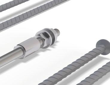
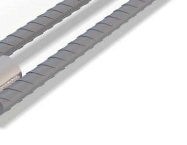
2 Anchoring Coupler For bolted connections Multi-purpose anchoring system for all bolted connections Simplifi es the process of installing bolted connections Prevents bars from protruding from the formwork Quick and easy installation into concrete with the help of standard accessories Transfers forces after precast elements are erected and nuts are tightened The Anchoring Coupler is a rebar anchor with female threads for bolted connections in precast concrete structures. is mainly used in foundation-to-column and column-to-beam connections in combination with HPKM / PEC Column Shoes or BECO Beam Shoes. Anchoring Couplers transfer tensile, compression, and shear forces through the connection during erection and in the final stage. can be adapted to all types of concrete structure. Hidden Anchoring Couplers with removable threaded bars avoid the risk of protruding parts being damaged during construction. The joint between the two precast concrete parts is grouted to finalize the connection.
3 Contents About Anchoring Coupler 4 1. Product properties Structural behavior Application conditions Loading and environmental conditions Interaction with base structure Positioning of the anchoring couplers Other properties Anchoring couplers with bent anchor bars Resistances Fire resistance Selecting Anchoring Coupler 14 Annex A - Supplementary reinforcement in lap zone 17 Annex B - Accessories 18 Installation of Anchoring Coupler 19 Install the Product Casting of Anchoring Couplers Install the Product Assembling Revision: 002


 with straight anchor bars; b) with headed anchor bars; c) double sided model.")
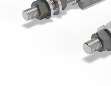
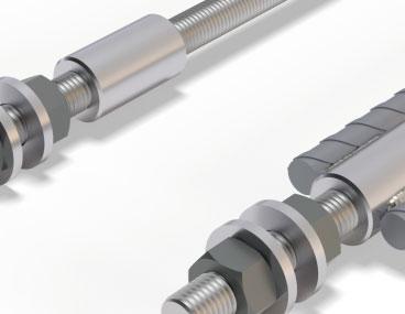
4 About Anchoring Coupler 1. Product properties Anchoring Couplers are used for connecting structural and non-structural elements to concrete loadbearing structures. Anchoring couplers consist of a removable threaded bar, which is installed on the building site, and an anchored coupler. The coupler is cast into base structure and anchored via one or more anchor bars. Anchoring Couplers are available in various standard or semi-standard models that are suitable for different applications. P Anchoring Coupler with straight anchor bar(s) L Anchoring Coupler with headed anchor bar(s) D Anchoring Coupler with double-sided arrangement Figure 1. Anchoring Coupler: a) with straight anchor bars; b) with headed anchor bars; c) double sided model. a) b) c) The P Anchoring Coupler transfers tensile forces by splicing anchor bars to the overlapping main reinforcement of the concrete member. Anchoring Coupler with straight anchor bars (Figure 1: a) is intended for use in structures with sufficient depth. Alternatively, the anchor bars may be bent to fit in shallow concrete members (see Figure 2). L Anchoring Coupler with headed anchor bars is primarily used in columns or other shallow structures (see Figure 1: b). The D Anchoring Coupler with one coupler on each side is suitable for transferring tensile forces throughout construction (e.g. connecting parts of the construction from opposite sides of the column see Figure 3). Anchoring couplers are cast into the construction together with the main and supplementary reinforcement (see section Installation of the Anchoring Coupler). The connection is assembled by placing the threaded bar into the coupler and fastening the base plate using a washer and nuts. Anchoring couplers can be designed to transfer axial and shear forces, as well as combinations thereof. 4 Anchoring Coupler

5 About Anchoring Coupler Figure 2. Anchoring Couplers in a single-sided beam-to-column connection. Figure 3. Anchoring Couplers in a double-sided beam-to-column connection. Version: Peikko Group 03/2017 5
6 About Anchoring Coupler 1.1 Structural behavior Anchoring Couplers are connecting elements that carry tensile, compression, and shear forces and transfer them into the base structure. Typically, the anchoring couplers are used to create moment-resistant connections. Forces can be transformed at precast beam-to-column or column-to-foundation connections. Other applications are also possible. The load transfer mechanisms of the Anchoring Coupler under different types of connections are shown in Figures 4, 5, and 6. Figure 4. Structural behavior of anchoring couplers in column-to-foundation connections. M Ed V Ed z F st,0 F sc,0 Figure 5. Structural behavior of anchoring couplers in beam-to-column connection. V Ed F st,0 z M Ed F sc,0 Shear force is transferred via corbel 6 Anchoring Coupler
7 About Anchoring Coupler Figure 6. Structural behavior of anchoring couplers in double-sided connections. F st,0 M Ed z M Ed F sc,0 Shear forces are transferred via corbels 1.2 Application conditions The standard models of P Anchoring Couplers with straight bars are pre-designed for use under the conditions mentioned in this section. The anchorage part of the L and D models must be designed on a project basis. The L Anchoring Coupler is a semi-standard model. The geometry of the concrete element must be taken into account to design the proper length of the headed anchor bars. Design should follow the requirements of standards EN or CEN/TS The double-sided Anchoring Coupler is a semi-standard model with pre-designed parts. The length of the double-sided anchoring coupler must be based on the geometry of the concrete member. See the section entitled Selecting a Anchoring Coupler for further details. If this condition may not be satisfied, please contact Peikko s Customer Engineering Service. Note: Anchoring Couplers must not be used as rebar couplers for reinforcement. Rebar Couplers from the Peikko product portfolio can be used to connect to the rebar Loading and environmental conditions Anchoring Couplers are designed to transfer static loads. To ensure resistance to corrosion, the concrete cover of the anchoring coupler, including washers and nuts, must observe the minimum values determined according to the environmental exposure class and intended operating life (EN ). For headed anchoring couplers, concrete cover refers to the forged head near the edge of the concrete element. Version: Peikko Group 03/2017 7
8 About Anchoring Coupler Interaction with base structure Anchoring Couplers are pre-designed for use in reinforced concrete structures such as columns, beams, and foundations. The properties of the anchoring couplers are valid for reinforced concrete with strength class in the range C25/30 to C50/ Positioning of the anchoring couplers Anchoring Couplers are cast into the concrete element up to the top of the coupler. The layout of the anchoring couplers should also consider the existing reinforcement to ensure the correct installation of the anchoring couplers and casting of all parts. 1.3 Other properties Anchoring Couplers are produced from structural steel rods, rebars and threaded bars with the following properties: Coupler S355J2 EN Ribbed bar B500B EN Threaded (load class H) bar (load class P) 8.8 High strength steel, property class 8.8 f yk 640MPa f uk 800MPa Washer S355J2+N EN Nut (load class H) (load class P) Property class 8 Property class 10 EN ISO Mechanical properties according to EN ISO EN ISO 4032/EN ISO Standard delivery for each anchoring coupler includes a threaded bar, two hexagon nuts, and two washers. Peikko Group s production units are externally controlled and periodically audited on the basis of production certifications and product approvals by various organizations, including Inspecta Certification, VTT Expert Services, Nordcert, SLV, TSUS, and SPSC, among others. Manufacturing method Ribbed bars Threads Welds Anchor heads Mechanical cutting Rolling MAG welding Forging Manufacturing tolerances Total length Threads ±10mm +5mm, -0mm 8 Anchoring Coupler
9 About Anchoring Coupler The dimensions of the standard models of Anchoring Couplers are summarized in Table 1, Table 2, and Table 3. Table 1. Dimensions of the P with straight anchor bar(s). l a Load class H l Co lco /2 Ø Ø c M l TB L l a Load class P l Co lco /2 Ø Ø c M l TB L 16H 20H Load class H 24H 30H 39H 30P 36P Load class P 39P 45P M M16 M20 M24 M30 M39 M30 M36 M39 M45 M52 l TB [mm] l Co [mm] Ø c [mm] P Ø [mm] Ø16 Ø20 Ø25 Ø32 Ø40 2Ø25 2Ø28 2Ø28 2Ø32 4Ø32 l a [mm] L [mm] Weight [kg] Color code Yellow Blue Gray Green Orange Black Red Brown Purple White NOTE: Lap lengths of standard length anchor bars are calculated for concrete grade C25/30 in good bond condition. Version: Peikko Group 03/2017 9
10 l Co l Co /2 About Anchoring Coupler Table 2. Dimensions of the L with headed anchor bar(s). Load class H l Co k Ø Ø c l Co /2 d h M l TB According to customer specifi cation Load class P k Ø Ø c d h M l TB According to customer specifi cation 16H 20H Load class H 24H 30H 39H 30P 36P Load class P 39P 45P M M16 M20 M24 M30 M39 M30 M36 M39 M45 M52 l TB [mm] l Co [mm] Ø C [mm] P Ø [mm] Ø16 Ø20 Ø25 Ø32 Ø40 2Ø25 2Ø28 2Ø28 2Ø32 4Ø32 d h [mm] k [mm] Color code Yellow Blue Gray Green Orange Black Red Brown Purple White NOTE: The total length of the headed anchoring bars should be defined according to the dimensions of the concrete member and verified according to CEN/TS Anchoring Coupler
11 About Anchoring Coupler Table 3. Dimensions of the double-sided D. Load class H l Co l Co l Co /2 l /2 Co Ø Ø c M According to customer specifi cation l TB Load class P l Co l Co l Co /2 l /2 Co Ø Ø c M According to customer specifi cation l TB 16H 20H Load class H 24H 30H 39H 30P 36P Load class P 39P 45P M M16 M20 M24 M30 M39 M30 M36 M39 M45 M52 l TB [mm] l Co [mm] Ø C [mm] P Ø [mm] Color code Yellow Blue Gray Green Orange Black Red Brown Purple White NOTE: The total length of the double-sided Anchoring Coupler should be defined according to the dimensions of the concrete member. The connecting bar in the double-sided H load class model is manufactured from ribbed bars with threads on both ends and can be produced with a minimum length of 350mm. The connecting bar in the P load class model is manufactured from weldable threaded bar Anchoring couplers with bent anchor bars The anchor bars in single-sided Anchoring Couplers may be bent to fit in shallow concrete members. The minimum dimensions of the bent part are specified in Table 4 and should be also taken into account when designing the bent anchoring couplers. Version: Peikko Group 03/
12 About Anchoring Coupler Table 4. Minimum dimensions of the bent part of the anchoring coupler. a min min. 5Ø L co Ø m,min b min min. 5Ø Ø 16H 20H 24H 30H 39H 30P 36P 39P 45P Ø [mm] Ø m,min [mm] L co [mm] a min [mm] b min [mm] P NOTE: The minimum mandrel diameter Ø m,min must be checked for each individual case according to EN section 8.3. The length of the bent anchor bars should be determined in accordance with EN : section 8.4 Figure 7. Anchorage length for bent anchoring couplers. l bd 12 Anchoring Coupler
13 About Anchoring Coupler 2. Resistances The resistances of Anchoring Couplers are determined by a design concept that makes reference to the following standards: EN :2004/AC:2010 EN :2005 VDI :2003 The resistances of Anchoring Couplers provided in this document are equal to the tensile resistances of the threaded bars used in the anchoring couplers. Table 5. Design values of tensile or compressive resistance of individual Anchoring Coupler. 16H 20H 24H 30H 39H 30P 36P 39P 45P 52P N Rd N Rd,0 [kn] NOTE: The tensile resistance shown in Table 6 may be reduced when L type parts with head(s) are used due to the close location to the concrete edge or a small anchorage length. Each case must be designed caseby-case and verified by a designer. Table 6. Design values of shear resistance of individual Anchoring Coupler. 16H 20H 24H 30H 39H 30P 36P 39P 45P 52P Erection Stage V Rd,0 [kn] Final Stage V Rd [kn] t Grout [mm] NOTE 1: The resistances V Rd and V Rd,0 are valid for thicknesses of grouting equal to t Grout and when counter nuts are used. NOTE 2: The design value of resistance of the anchoring couplers from load class H correspond to the resistance of the HPM Anchor Bolts and load class P corresponds to the resistance of the PPM Anchor Bolts. NOTE 3: The resistances shown in Table 5 and Table 6 are without the simultaneous action of axial and shear load. For combined resistance, use the HPM Technical manual section 2.2. NOTE 4: The shear resistance of the Anchoring Coupler is not applicable in combination with the BECO Beam Shoe. For more information, please see the BECO Technical manual. 2.1 Fire resistance The concrete cover of the anchoring couplers should be at least equivalent to the concrete cover of the reinforcement of the concrete element to ensure adequate fire protection of the coupler. If the fire resistance of the connection is judged to be insufficient, the concrete cover of the anchoring coupler must be increased. Version: Peikko Group 03/
14 Selecting Anchoring Coupler The following aspects must be considered when selecting an appropriate type of Anchoring Coupler to be used in bolted connections: Resistances Position and arrangement of the anchoring couplers in the load-bearing structure Design values of loads The resistance of the Anchoring Coupler must be verified at following stages: Erection stage Final stage In the event of a fire Product code After selecting the correct Anchoring Coupler, a product code describing the product may be defined according to the description in Figure 8. Please use this code in drawings and when ordering the product from Peikko s Sales Service. Figure 8. Product code of single-sided Anchoring Couplers. l e Ø m 90 a Product Name M-Thread dimension Load class - H or P Shape of anchor bar, Table 7 Length [mm] Bend distance [mm] Mandrel diameter ϕ m [mm] XXY-Shape-l e (a-(dxx)*) *Mandrel diameter must be defined only if the value differs from minimum requirements of EN , section 8.3. Length of P with straight anchor bar/s: l l l e bd Co where: l Co = length of the coupler, Table 1 [mm] l bd = anchorage length, Figure 7 [mm] = for standard models l bd = l a, Table 1 [mm] 14 Anchoring Coupler
15 Selecting Anchoring Coupler Figure 9. Product code of double-sided Anchoring Couplers. l e h NP l e h NP a) without nailing plates b) with nailing plates Product Name M-Thread dimension Load class - H or P Shape of anchor bar, Table 7 Length [mm] XXY-D-l e Length of the double sided anchoring coupler le hc 2 hnp where: h c = column width [mm] h NP = thickness of nailing plate [mm], see section Annex B Accessories [mm] NOTE: The thickness of nailing plates should be taken into account only in cases where nailing plates are used. Table 7. End types and bending shapes of Anchoring Couplers. Shape codes according to EN ISO P - Straight end D - Double sided L- Headed stud P D L P12 90 Version: Peikko Group 03/
16 Selecting Anchoring Coupler Examples of product codes in various situations M20 M20 Tensile or compression force for each anchoring coupler N Ed = 87kN Selected 20H Tensile resistance N Rd = 96kN N Ed < N Rd 87 < 96kN Item 1. Bended anchoring coupler with rebar as anchor bar 20H-P (370) Item 2. Headed anchoring coupler 20H-L M39 Tensile or compression force for each anchoring coupler N Ed = 458kN Selected 39P Tensile resistance N Rd = 521kN N Ed < N Rd 458 < 521kN Item 3. Double-sided anchoring coupler. Nailing plate 39P-D Item 4. Double-sided anchoring coupler. Nailing plates are used for installation to the formwork. The length of the anchoring coupler is reduced by the thickness of nailing plates P-D M20 Tensile or compression force for each anchoring coupler N Ed = 70kN Selected 20H Tensile resistance N Rd = 96kN N Ed < N Rd 70 < 96kN Anchoring Coupler with straight anchor bar H-P Anchoring Coupler
17 Annex A - Supplementary reinforcement in lap zone Anchoring Couplers with straight bars are spliced with the main reinforcement of the base structure. The main reinforcement in the base structure must be at least equal to the cross-section of the anchorage reinforcement of the anchoring coupler. In accordance with EN , the lap zone should be reinforced with a sufficient amount of transverse reinforcements ΣA st (see Table 8 for the minimum amounts of transverse reinforcement). Table 8. Transverse reinforcement in lap zone. 16H 20H 24H 30H 39H 30P 36P 39P 45P 52P Σn st (4+4) Ø6 (4+4) Ø8 (4+4) Ø8 (5+5) Ø10 (7+7) Ø12 (5+5) Ø8 (5+5) Ø10 (6+6) Ø10 (6+6) Ø10 (6+6) Ø10 l O [mm] NOTE: Transverse reinforcement is defined for anchoring couplers under tensile load. Figure 10. Placing of transverse reinforcement at lap zone. S S l o /3 A st /2 S l o /3 A st /2 l o L Version: Peikko Group 03/

18 Annex B - Accessories Nailing plates Screw-in nailing plates can be used to fix Anchoring Couplers to the mold as an optional solution. Nailing plates are available for all product ranges of anchoring couplers. To ensure that the thread of the coupler will be clean after casting, it is recommend to apply some grease to the thread. Thread h NP Thread [mm] M16 M20 M24 M30 M36 M39 M45 M52 h NP [mm] Color code Yellow White Gray Red Black Green Pink Anthracite Gray Installation template In cases where anchoring couplers are placed in vertical positions in groups, the correct position of the anchoring couplers can be secured using the PPL Installation Template. It enables groups of anchoring couplers to be centralized and the correct position to be assured in relation to the horizontal plate. For more information, please see the PPL BOLT Installation Template leaflet. Ordering PPL Installation Templates When PPL Installation Templates are ordered, the thread diameter of anchoring couplers, the number of bolts, and the center-to-center dimensions must be specified. Examples of installation plates: 1) PPL x 360: 4 pieces M39 bolts in square form. 2) PPL x ( ): 6 pieces M30 bolts in rectangular form Anchoring Coupler
 defined by the M-thread diameter of the bolt.")

19 Installation of Anchoring Coupler Install the Product Casting of Anchoring Couplers Identification of the product Anchoring Couplers are available in models (16, 20, 24, 30, 36, 39, 45, 52) defined by the M-thread diameter of the bolt. The model of anchoring coupler can be identified by the name on the label on the product and the color of the product. Table 9. Color code of Anchoring Couplers. Anchoring Coupler Thread diameter Color code 16H M16 Yellow 20H M20 Blue 24H M24 Gray 30H M30 Green 39H M39 Orange 30P M30 Black 36P M36 Red 39P M39 Brown 45P M45 Purple 52P M52 White Version: Peikko Group 03/

20 Installation of Anchoring Coupler Installation tolerances Anchoring couplers are installed at the precast factory. The height level of the anchoring coupler is defined by the formwork or an installation template. The maximum height installation tolerance in precast elements is ±2 mm. The installation tolerances for groups of anchoring couplers are shown in the following table. Δx Δy 16H 20H 24H 30H 39H 30P 36P 39P 45P 52P Δx [mm] ±3 ±3 ±3 ±3 ±3 ±3 ±4 ±4 ±4 ±5 Δy [mm] ±3 ±3 ±3 ±3 ±3 ±3 ±4 ±4 ±4 ±5 Installation of Anchoring Couplers Anchoring couplers are placed into the reinforcing cage and screwed to the formwork wall. It is recommended to place some grease on the coupler thread before screwing it into the mold. This prevents the coupler from being filled with concrete during casting. After the concrete element is cast, the connecting nuts are removed from the mold and the concrete element is removed from the formwork. NOTE: Optionally, nailing plates can be used to attach the couplers to the formwork. See Annex B Accessories. 1) Placing the anchoring couplers into the reinforcing cage of the column. 2) Placing the column reinforcement with anchoring couplers to the formwork. Fixing anchoring couplers with bolts. 20 Anchoring Coupler
 Installing the threaded bars with nuts at building site.")


 Placing reinforcement and anchoring couplers into the formwork.")
21 Installation of Anchoring Coupler 3) Casting the column and demolding the element. 4) Installing the threaded bars with nuts at building site. Installation to foundation Anchoring couplers are placed into the reinforcing cage and screwed to the installation template with threaded bars and nuts. The foundation is filled with concrete. When the concrete element hardens to the required strength, the installation template is removed and used for another group of anchoring couplers. The lower nuts are leveled to the correct position before the attachment is erected. 1) Placing reinforcement and anchoring couplers into the formwork. The installation template ensures the correct position of the anchoring coupler. 2) Casting the foundation. 3) Removing the installation template and leveling the lower nuts to the correct position. Version: Peikko Group 03/
22 Installation of Anchoring Coupler Install the Product Assembling Erection of the attachment Vertical attachment (Figure 11) Before placing the vertical attachment into the final position, screw the threaded bar onto the coupler and tighten it with two nuts (see Figure 11). Interlocking between two nuts enables the threaded bar to be fastened to the coupler. The top nut is removed from the threaded bar. The lower nuts with washers are leveled into the final position. The attachment is placed in the final position. The lower nuts are adjusted as needed. The top washers and nuts are placed onto the threaded bars and tightened. After the nuts are tightened, the precast element can be detached from the crane. Figure 11. Installation of the threaded bars to the couplers. Threaded bar Remove top nut Level bottom nut to fi nal position 22 Anchoring Coupler
23 Installation of Anchoring Coupler Horizontal attachment (Figure 12) Before placing the horizontal attachment in the final position, the thread protection plastic plugs are removed from the coupler. The horizontal attachment is placed on the column corbel (steel or elastic shim plate). The threaded bar is placed through the casting box into the coupler and tightened with two nuts. Interlocking between two nuts enables the threaded bar to be fastened to the coupler. Shim plates are placed between the column and horizontal attachment. The top washers and nuts are screwed into the final position and tightened. 1. Install the precast beam in the column corbel 2. Insert threaded bars through the beam shoe and screw them to the couplers. Threaded bars are tightened to the couplers using two nuts. 3. Remove the top nuts and tighten the lower nuts in their final position. Figure 12. Horizontal attachment to anchoring couplers. 1) 2) 3) NOTE: Threaded couplers must be clean and dirt-free before the threaded bar is screwed into the coupler. The gap in the connection must be then grouted with non-shrinking mortar. The connection is finalized after the grouting has hardened to the sufficient strength and the structure can take the load of upper-floor elements. Version: Peikko Group 03/
24 Notes 24 Anchoring Coupler
25 Notes Version: Peikko Group 03/
26 Notes 26 Anchoring Coupler
27 Technical Manual Revisions Version: PEIKKO GROUP 03/2017 Revision:002* New cover design for 2018 added. Version: Peikko Group 03/
28 Resources DESIGN TOOLS Use our powerful software every day to make your work faster, easier and more reliable. Peikko design tools include design software, 3D components for modeling programs, installation instructions, technical manuals and product approvals of Peikko s products. peikko.com/design-tools TECHNICAL SUPPORT Our technical support teams around the world are available to assist you with all of your questions regarding design, installation etc. peikko.com/technical-support APPROVALS Approvals, certificates and documents related to CE-marking (DoP, DoC) can be found on our websites under each products product page. peikko.com/products EPDS AND MANAGEMENT SYSTEM CERTIFICATES Environmental Product Declarations and management system certificates can be found at the quality section of our websites. peikko.com/qehs
CARES Technical Approval Report TA1-B & C 5059
 CARES Technical Approval Report TA1-B & C 5059 Issue 2 DEXTRA Griptec Anchors Assessment of the Griptec Anchors Product and Quality System for Production 5059 Product DEXTRA Griptec Anchors for reinforcing
VSL MINING & TUNNELING SYSTEMS VSL. mining and tunneling
 VSL MINING & TUNNELING SYSTEMS VSL mining and tunneling VSL Mining & Tunneling Bolt systems VSL offers three type of bolting system for the mining & Tunnelling industry VSL-S Solid Threaded bolts. Continuous
FLEXIBLE AND RELIABLE ANCHORING
 Spiral rope anchor and FLEX Head FLEXIBLE AND RELIABLE ANCHORING 1 THE SMARTER ANCHOR FLEXES. The flexibility of the whole system is crucial for both rockfall barriers and other protection systems. Why?
fischer Epoxy Mortar FIS EB The basic epoxy mortar for applications in concrete
 fischer Epoxy Mortar FIS EB The basic epoxy mortar for applications in concrete For standard applications in concrete and rebar connections. Advantages at a glance Epoxy mortar for applications in concrete
WEDGE-ALL Wedge Anchors
 WEDGE-ALL Wedge Anchors The Wedge-All wedge anchors are a non-bottom bearing, wedge-style expansion anchor for use in solid concrete or grout-fi lled masonry. A one-piece clip ensures uniform holding capacity
Also suitable for: Concrete C12/15. For fixing of: Steel constructions Railings Consoles Ladders Wooden constructions Cable trays Machines Staircases
 28 Highbond anchor FHB II Flexible installation and highest loads in the cracked tensile zone. OVERVIEW FHB II-A S (standard), zinc plated steel FHB II-A L (performance optimised), zinc-plated steel Resin
COMPFIRE CCFT-FP_550_55_ September 2010 Fin Plate Connection to Circular Concrete-Filled Tube Test Result
 Reaction Frame Macalloy Bars Camera 3 Support Beam α Oven Bar Camera 2 Link Bar Camera 1 Tested Connection Jack Bar Electrical Furnace Reaction Frame Load Jack v2_5 April 2011 1 Oven Bar Link Bar View
fischer Epoxy Mortar FIS EB
 fischer Epoxy Mortar FIS EB The basic epoxy mortar for applications in concrete ETA-15/0771 ETAG 001-5 Post-installed rebar connection (TR2 fischer Epoxy Mortar FIS EB: For standard applications in concrete
Highbond anchor FHB II-A S
 Highbond anchor FHB II-A S The best performance in cracked concrete with the least installation effort VERSIONS APPROVALS zinc-plated steel stainless steel high corrosion-resistant steel ADVANTAGES BUILDING
Injection mortar FIS VL
 Injection mortar FIS VL The solid injection mortar for standard applications in cracked concrete and masonry High-bay warehouses BUILDING MATERIALS Approved for anchorings in: Concrete C20/25 to C50/60,
SOFRASAR TUNNEL PRODUCTS CONNECTING ALL COMPONENTS
 www.optimas.com SOFRASAR TUNNEL PRODUCTS CONNECTING ALL COMPONENTS CONTENTS DOWEL SYSTEM SOF-FIX AXIS 110 PG. 06 DOWEL SYSTEMS 04 BOLTING SYSTEMS 08 GROUT LIFT SOCKETS 11 CENTERING DOWELS AND SHEAR DOWELS
TZ WEDGE ANCHOR FOR CRACKED AND UNCRACKED CONCRETE
 www.ucanfast.com TECHNICAL MANUAL SECTION 2.2 PAGE 1 / 10 ä DESCRIPTION UCAN TZ torque controlled mechanical expansion wedge anchors have a Category 1 classification. They are used to resist static, wind
Utility Anchor System
 Utility Anchor System The Dayton Superior Utility Anchor System is designed to economically simplify the lifting and handling of precast concrete elements. Its economics, ease of use and versatility will
The cost-efficient fixing for flexible use in non-cracked concrete VERSIONS. zinc-plated steel stainless steel hot-dip galvanised steel
 The cost-efficient fixing for flexible use in non-cracked concrete VERSIONS APPROVALS zinc-plated steel stainless steel hot-dip galvanised steel BUILDING MATERIALS Approved for: Concrete C20/25 to C50/60,
Ancholt Bolt Design With Tension and Shear Using Anchor Reinforcement
 Page 1 of 8 ANCHOR BOLT DESIGN Combined Tension and Shear Result Summary Anchor Rod Embedment, Spacing and Edge Distance OK Min Rquired Anchor Reinft. Development Length ratio = 0.87 OK Overall ratio =
The first and only continuous tension holdown system.
 The first and only continuous tension holdown system. CANADA LIMIT STATES EDITION FEBRUARY 2017 Earthbound Seismic and Wind Holdown Systems. The industry leader in hardware and design technology. FEATURES
Submittal / Substitution Request
 Submittal / Substitution Request SUBMITTED TO: To: Firm: Project: Submitted Product: SIMPSON STRONG-TIE WEDGE-ALL WEDGE ANCHOR Specified Product: Section: Page: Detail/Sheet No.: Description of Application:
OPERATION AND INSTRUCTION MANUAL Swivel Anchor Model: SWY100N
 OPERATION AND INSTRUCTION MANUAL Swivel Anchor Model: SWY100N Patent # US 8,424,638 WARNING: ALL PERSONS USING THIS EQUIPMENT MUST READ AND UNDERSTAND ALL INSTRUCTIONS. FAILURE TO DO SO MAY RESULT IN SERIOUS
Introduction Introduction
 Introduction Maritime International is a leading manufacturer of marine bollards and cleats worldwide. Our range of bollards and cleats is unsurpassed by any other manufacturer or supplier. Maritime can
 TYPE: LSF - LIFTING STUD FOOT ANCHOR DESCRIPTION: The design of the anchor means no additional reinforcement is required as the forces are transferred into the concrete from the design of the foot of the
SET OF EUROLEAGUE BACKSTOP UNITS (Reference PK120)
") SET OF EUROLEAGUE BACKSTOP UNITS (Reference PK120) DESCRIPTION The EUROLEAGUE backstop unit is mainly designed for multi-sports pavilions and installations where the highest-level basketball competitions
SET OF EUROLEAGUE BACKSTOP UNITS (Reference PK120) DESCRIPTION The EUROLEAGUE backstop unit is mainly designed for multi-sports pavilions and installations where the highest-level basketball competitions
Plummer Block Housings
 Plummer Block Housings TECHNICAL INFORMATION Feature The majority of SLB Plummer Block Housing is made of Gray Cast Iron and is of the models of 'SN', 'SNU' and 'SAF'. Its basic size conforms with 'ISO'
Supplementary instructions. Rod and cable components. for VEGAFLEX series 80. Document ID: 44968
 Supplementary instructions Rod and cable components for VEGAFEX series 80 Document ID: 44968 Contents Contents 1 Product description 1.1 Extensions... 3 2 Mounting 2.1 General instructions... 6 2.2 Rod
Technical Manual. Stand 05/2011
 MULTI-MONTI Technical Manual Stan5/2011 Technical Manual HECO-MULTI-MONTI Contents Instructions for fixing P. 3 Chapter 1 : Admissible loads in as well as P. 4 anchor-characteristics for MMS-6 to MMS-16
CHEMICAL. Straight cut rod is provided in the materials listed below and includes nuts / washers.
 161 STRAIGHT CUT ROD Straight cut rod is provided in the materials listed below and includes nuts / washers. Straight Rod 22-1/2 Bent Rod A 307 THREADED ANCHOR ROD, ZINC PLATED (ASTM B633, CLEAR CHROMATE)
FP McCann Tunnels and Shafts 1
 FP M c Cann FP McCann Tunnels and Shafts 1 The McCann range of shaft and tunnel products have been developed to meet the requirements of the latest industry standards which include the British Tunnelling
OPERATION AND INSTRUCTION MANUAL Swivel Anchor Model: SWY100N
 OPERATION AND INSTRUCTION MANUAL Swivel Anchor Model: SWY100N IMPORTANT!!! ALL PERSONS USING THIS EQUIPMENT MUST READ AND UNDERSTAND ALL INSTRUCTIONS. FAILURE TO DO SO MAY RESULT IN SERIOUS INJURY OR DEATH.
TorqBolt Wedge Anchors Torque Controlled Expansion Anchor
 TorqBolt Wedge Anchors Torque Controlled Expansion Anchor Product Description The Torqbolt wedge anchor is a torque-controlled, wedge expansion anchor for heavy duty fastening applications where high pull
Mechanical Anchoring Systems HDA Undercut Anchor Product description. HDA-P Undercut Anchor Pre-Set Type
 Mechanical Anchoring Systems 3.3 3.3.1 HDA Undercut Anchor 3.3.1.1 Product description The Hilti HDA undercut anchor is a heavy-duty mechanical anchor with carbide-tipped undercut segments used to perform
MANUAL. Sesame. Thermoplastic Tank Technologies
 MANUAL Sesame Thermoplastic Tank Technologies INSTALLATION AND USER GUIDE CONTENT 1. GENERAL 3 2. IMPORTANT 3 3. INSTALLATION EXPANSION VESSEL 4 4. USE EXPANSION VESSEL 5 5. AIR CELL REPLACEMENT 5 5.1
PUSH PIER SYSTEMS STABILITY. SECURITY. INTEGRITY. Push Pier Systems PN #MBPPT
 PUSH PIER SYSTEMS STABILITY. SECURITY. INTEGRITY. PN #MBPPT Push Pier Systems About Foundation Supportworks is a network of the most experienced and knowledgeable foundation repair and new construction
TECHNICAL SPECIFICATION
 lifting anchor system The T-slot The T-slot lifting anchor system...1 Introduction...2 The T-slot anchor...3 The O-anchor...3 The P-anchor...3 The TKS rod-anchor...3 The TPA plate-anchor...3 The TKA tilting
MULTI-MONTI Technical manual
 MUTI-MONTI Technical manual Version 01/2017 Technical manual MUTI-MONTI Content Instructions for fixing P. 3 Chapter 1: Admissible loads in as well as P. 4 anchor characteristics for MMS-6 to MMS-16 1.1
SAFETY JOURNAL FOR GIPFEL WEDGE ROCK ANCHOR BOLTS
 SAFETY JOURNAL FOR GIPFEL WEDGE ROCK ANCHOR BOLTS NOTE: Here we are only talking about the wedge type expansion bolts. How do rock anchors fail? A rock anchor assembly mainly comprises of a Hanger and
BARRIER OFFSET 0" A 6" 6" A 12" 12" A 26" A 26" 3A OR 4A L OR S * ** L OR S L OR S
 ACCEPTABLE (TCB) TYPES AND ANCHORING DETAILS BASED ON UNDERLYING SURFACE TYPE AND BARRIER OFFSET FROM DROP-OFF BARRIER OFFSET UNDERLYING SURFACE 0" A 6" 6" A 12" 12" A 26" A 26" TCB TYPE DETAIL TCB TYPE
OPERATION AND INSTRUCTION MANUAL
 OPERATION AND INSTRUCTION MANUAL Dual Extension Swivel Anchor Model: SWD100N-036 WARNING: ALL PERSONS USING THIS EQUIPMENT MUST READ AND UNDERSTAND ALL INSTRUCTIONS. FAILURE TO DO SO MAY RESULT IN SERIOUS
DESIGN OF AXIALLY LOADED STEPPED FOOTING DATA :- SBC of soil =200 KN /m 2 Concrete Mix =M20 Steel Grade = Fe 415 Clear cover of bottom slab =50 mm
 STEPPED FOOTING The construction of sloped footing is sometimes difficult and when the slope of the top face of footing is more, say more than 1 vertically to 3 horizontally, it may be difficult to finish
OPERATION AND INSTRUCTION MANUAL Swivel Anchor Model: HD26248
 OPERATION AND INSTRUCTION MANUAL Swivel Anchor Model: HD26248 IMPORTANT!!! ALL PERSONS USING THIS EQUIPMENT MUST READ AND UNDERSTAND ALL INSTRUCTIONS. FAILURE TO DO SO MAY RESULT IN SERIOUS INJURY OR DEATH.
Hilti, Inc South 122 nd East Avenue Tulsa, OK
 Attached are page(s) from the 2011 Hilti North American Product Tech Guide. For complete details on this product, including data development, product specifications, general suitability, installation,
Technical Data Sheet TI-F50 Locking Units series KFH
 English translation of German original Locking Units series KF Further important practical advice is given in Operating Manual BA-F50., Rod diameter 18 mm 50 mm øz 8 L 2 6 x 6 0 min. 4x30 KF 18 to KF 32,
Self-drilling hollow anchor bolts and accessories
 Self-drilling hollow anchor bolts and accessories Application During the constructions of underground works, it is very common to encounter soft rock, fractured zone and large deformation due to high ground
Push-in fittings NPQH
 Key features Application Effortless selection of the right fitting. Festo offers a secure solution for every connection. The convenient push-in fitting system includes well over 1000 types of standard
Manual winch MANISTOR 100 and 200
 Manual wall winch Manual winch MANISTOR 100 and 200 Instruction manual UK 173-192.10-3 PRODUCT DEVELOPED AND MANUFACTURED ACCORDING TO NF EN 13157 STANDARD REGISTERED DESIGN To ensure the constant improvement
l DESCRIPTION l FEATURES l LIMITATIONS l TYPICAL APPLICATIONS l MATERIAL SPECIFICATIONS TECHNICAL MANUAL SECTION 2.3 PAGE 1 / 6
 www.ucanfast.com TECHNICAL MANUAL SECTION 2.3 PAGE 1 / 6 l DESCRIPTION The UCAN WAG anchor is a fully threaded torque controlled expansion anchor assembled with a three segment expansion clip. All parts
IMPORTANT: If you have questions on the use, care, or suitability of this equipment for your application, contact DBI/SALA.
 User Instruction Manual Precast Concrete Beam Horizontal Lifeline System This manual is provided as the Manufacturer s Instructions, and should be used as part of an employee training program as required
Made in the USA. For Fall Protection Only. SafeLok Part Description
 Operations and Instruction Manual SafeLok Anchorage - Model # 4011 IM-0051 REV A Portable Concrete and Steel Anchorage Connector ANSI Z359.1-07 5,000 lbs / 22kn Made in the USA The 3/4 Fall Protection
DYWIDAG Form Tie Systems
 DYWIDAG Form Tie Systems 2 DYWIDAG Form Tie System The DYWIDAG Form Tie System is based on the original DYWIDAG Threadbar with hot-rolled, continuous thread on both sides. Together with matching accessories,
Floor Mount Socket. T: +44 (0) F: +44 (0)
 F: +44 (0)") G-Davit : Floor Mount Socket USER INSTRUCTION MANUAL A davit socket for installation bolted to a high strength flooring material. Suitable for both fall arrest use and lifting. EN795 Class B, PPE Anchor
G-Davit : Floor Mount Socket USER INSTRUCTION MANUAL A davit socket for installation bolted to a high strength flooring material. Suitable for both fall arrest use and lifting. EN795 Class B, PPE Anchor
Operations and Instruction Manual Might Swivel Model # Concrete and Steel Anchorage Connector ANSI Z ,000 lbs / 44kn
 Operations and Instruction Manual Might Swivel Model # 00238 Concrete and Steel Anchorage Connector ANSI Z359.1 10,000 lbs / 44kn Description: Zinc plated forged heat treated steel, Special design gives
SECTION BUTTERFLY VALVES
 SECTION 15112 BUTTERFLY VALVES PART 1 GENERAL 1.01 SUMMARY A. All butterfly valves shall be of the tight closing, rubber seated type and fully comply with the latest revision of AWWA Standard C504, Class
MANUAL SEALLESS STEEL STRAPPING TOOL MODEL A
 OPERATION MANUAL / SPARE PARTS LIST MANUAL SEALLESS STEEL STRAPPING TOOL MODEL A337.0001 13.1912.01 13191201.en/MAS/ 10.02 INDEX PAGE 1 SAFETY INSTRUCTIONS 2 2 WARRANTY CONDITIONS AND LIABILITY 4 3 APPROPRIATE
LYSAGHT W-DEK. Design and Construction Manual. Structural steel decking system
 LYSAGHT W-DEK Structural steel decking system Design and Construction Manual ptimised to bring greater efficiency, speed of construction and economy. Exceptional spanning characteristics (up to 4.1m) reduces
Foundation Products. Poured In Ground Anchor Bolts E1 - E4. Structural Foundations E5 - E12. Copyright 2016 s Industry Inc. SIE-RA-CMP EN
 Foundation Products Poured In Ground Anchor Bolts E1 - E4 Structural Foundations E5 - E12 EA EB Poured in Ground Anchor Bolts Layout SIEMENS Anchor Bolts 131702-4X shown for reference purposes only! Actual
MEVA Guided Climbing MGC Technical Instruction Manual
 MEVA Guided Climbing MGC Technical Instruction Manual Product Features MGC is the abbreviation for MEVA Guided Climbing and the name of MEVA s guided climbing system. Guided climbing means that after each
Content Technical Data R R38 7-8
 http://www.maxdrill.com.cn Content Technical Data R25 4 R32 5-6 R38 7-8 R51 9 T76 10 1 GUIDE OF PRODUCT CODE : Bit:25 M R 30 0 42 http://www.maxdrill.com.cn A B C D E F A Connect size 25 32 38 51 76 B
Products. reinforcement. systems. Reinforcement. systems
 Products Reinforcement Productvideo www.nevoga.com system Plexus, Pyraplex, FTW PLEXUS PLEXUS is a prefabricated rebar continuity system for reinforced concrete construction. PLEXUS provides a simple and
1000/13.02 KOBSERT. Thread inserts for metals
 1000/13.02 KOBSERT Thread inserts for metals Contents KOBSERT Thread inserts for metals Page The principle 3 The benefits 3 Product types 3 Applications in the Automotive and General industry 4 Technical
OPERATION AND INSTRUCTION MANUAL
 OPERATION AND INSTRUCTION MANUAL Swivel Anchor Model: SWS100N-316-CTS Patent US # 8,424,638 WARNING: ALL PERSONS USING THIS EQUIPMENT MUST READ AND UNDERSTAND ALL INSTRUCTIONS. FAILURE TO DO SO MAY RESULT
Extension Platform. Base Platform. Crossover. Exit railing. Exit Railing
 Base Platform Galvanized With metal grate and two brackets Railing on the long side and a face side Extension Platform Galvanized With metal grate and one bracket Railing on the long side with rail connection
The Industrial Accident Resulted from the Failure of Bolt
 The Industrial Accident Resulted from the Failure of Bolt Hyun Wook YEO 1, Jae Min LEE 2 and Sang Won CHOI 1, * 1 Occupational Safety and Health Research Institute, Korea Occupational Safety and Health
Drop-In Internally Threaded Anchor (DIAB) Mechanical Anchors. Key features. Material: Carbon steel. Coating: Zinc plated
 Mechanical Anchors. Key features. Material: Carbon steel. Coating: Zinc plated") Drop-In Internally Threaded Anchor (DIAB) Expansion shell anchors for use in solid base materials Simpson Strong-Tie introduces a new, redesigned Drop-In Anchor (DIAB) that provides easier installation
Drop-In Internally Threaded Anchor (DIAB) Expansion shell anchors for use in solid base materials Simpson Strong-Tie introduces a new, redesigned Drop-In Anchor (DIAB) that provides easier installation
WELCOME to CAUx Local India 2018
 WELCOME to CAUx Local India 2018 Flange Design In Detail Prepared by Sachin Pol and Fauzan Badiwale Some Typical Flange Images 3 Some Typical Gasket Images 4 Flange Design As Per ASME Sec.VIII Div.1 Mandatory
TECHNICAL INFORMATION
 TECHNICAL INFORMATION Models No. TD0101, TD0101F Description Impact Driver L PRODUCT P 1/ 14 CONCEPT AND MAIN APPLICATIONS Models TD0101 and TD0101F are cost-competitive 100N.m-class impact driver developed
Safety System Installation Guide for ARE Wind Poles
 Safety System Installation Guide for ARE Wind Poles V. 1 May 2011 ** Climbing pegs and ladder should be installed before the pole is erected.** A. Install climbing pegs Install climbing pegs (bolt set)
Mounting and Operating Instructions EB 3007 EN. Self-operated Pressure Regulators. Differential Pressure Regulators (opening) Type Type 42-25
 Type Type 42-25") Self-operated Pressure Regulators Differential Pressure Regulators (opening) Type 42-20 Type 42-25 Type 42-20 Differential Pressure Regulator Type 42-25 Differential Pressure Regulator Mounting and Operating
Self-operated Pressure Regulators Differential Pressure Regulators (opening) Type 42-20 Type 42-25 Type 42-20 Differential Pressure Regulator Type 42-25 Differential Pressure Regulator Mounting and Operating
LOAD-BEARING SHEETS SAFETY ANCHOR SA
 www.ruukki.com LOAD-BEARING SHEETS SAFETY ANCHOR SA 113-153 INSTRUCTIONS FOR USE Contact Information Please see your local contact information from www.ruukki.com Figure 1. Cross-section of the safety
E10 E10 E10 E10 E10 E10 E10 E10 E10 E10 E10 E10 E10 E10. Cable gland Series 8161/7, 8161/8. Installation Equipment and Accessories E10/1.
 > Explosion protection type "Increased safety" > Degree of protection IP68 > Ex e and Ex i versions > Integrated blind plug (accessory) for closing unused cable glands > Cable diameter ranges from 1 to
DOUBLE SAFETY: NO PANIC, NO BACTERIA
 Panic and emergency exit DOUBLE SAFETY: NO PANIC, NO BACTERIA In line with its attention to safety, ISEO has decided to add this measure to a device which is always present in public environments and in
indoor / outdoor INSTALLATION GUIDE
 indoor / outdoor INSTALLATION GUIDE TEQBALL ONE INSTALLATION GUIDE This document contains a description of the Teqball One multifunctional sports equipment installation. This guide recommends using specific
Research on Shear Test methods of bonded steel bolts
 Research on Shear Test methods of bonded steel bolts *Quan Xueyou 1), Li Xiongsong 2) and Luo Chujie 2) 1), 2) School of Civil Engineering, Chongqing University 1), 2) Key Laboratory of New Technology
Fall Arrest Anchor Solutions
 Y O U L L N E V E R B E B E T T E R P R O T E C T E D Fall Arrest Anchor Solutions EACH TYPE TESTED AT THE NATIONAL ENGINEERING LABORATORY Roofanka and Ridganka CE approved to the PPE Directive COMPREHENSIVE
Materials : Dichromate zinc plated steel flanges or AISI 316
 Size : Ends : Min Temperature : Max Temperature : DN 25 to 300 Flanges PN10/16-35 C + 90 C Max Pressure : 16 Bars (10 bars at 90 C) Specifications : Absorb vibrations and noise Linear and angular compansion
Hilti, Inc South 122 nd East Avenue Tulsa, OK
 Attached are page(s) from the 2014 Hilti North American Product Tech Guide. For complete details on this product, including data development, product specifications, general suitability, installation,
Continental Industries TRANSITION FITTINGS or FAX Visit
 Continental Industries TRANSITION FITTINGS 1-800-558-1373 or FAX 1-800-788-1668 Visit www.conind.com ABOUT US Our Company Continental Industries, headquartered in Tulsa, Oklahoma, was formed in 1958 and
ISO INTERNATIONAL STANDARD. Personal protective equipment for protection against falls from a height Single-point anchor devices
 INTERNATIONAL STANDARD ISO 14567 First edition 1999-03-01 Personal protective equipment for protection against falls from a height Single-point anchor devices Équipements individuels de protection contre
CHAIN LINK FENCE GATE
 WALCOOM Walcoom Corporation CHAIN LINK FENCE GATE Chain link fence gate is a versatile product in many aspects, here, Walcoom provides buyers with sufficient strength and durability chain link fence gate
Section GATE VALVES
 Section 02521 PART 1 GENERAL 1.01 SUMMARY This Section includes the furnishing and installation of gate valves for isolation and dead-end service as shown on Plans and as specified herein. 1.02 MEASUREMENT
Code Compliance Research Report CCRR-0145
 Code Compliance Research Report CCRR-0145 Issued: 11-16-2009 Renewal Due: 11-18-2018 Revised: 11-28-2017 DIVISION: 05 - Metals Section: 05 50 00 Metal Fabrications MARSHALL STAMPING COMPANY 355 Glade Mills
Mounting and Operating Instructions EB EN. Type Supply Pressure Regulator. with increased air capacity
 Type 4708-45 Supply Pressure Regulator with increased air capacity Translation of original instructions Mounting and Operating Instructions EB 8546-1 EN Edition March 2016 Note on these mounting and operating
OPERATION AND INSTRUCTION MANUAL Beam Trolley Model: BTA012N
 OPERATION AND INSTRUCTION MANUAL Beam Trolley Model: BTA012N WARNING: ALL PERSONS USING THIS EQUIPMENT MUST READ AND UNDERSTAND ALL INSTRUCTIONS. FAILURE TO DO SO MAY RESULT IN SERIOUS INJURY OR DEATH.
K0709 Quick-fit couplings
 Joints 1067 K0709 Quick-fit couplings with radial offset compensation external thread D1 SW SW1 application example: X max. D D 3 4 internal thread SW 3 4 2 SW1 D D Coupling part and claw in steel. Nut
Low Wind High Yields Series
 Low Wind High Yields Series Wind Turbines USER S MANUAL Introduction Low Wind High Yields Series rotor blades apply the latest advanced thermoplastic engineering and are manufactured by precision injection
EEF. Fatigue Testing Unit PROCESS DIAGRAM AND UNIT ELEMENTS ALLOCATION. Engineering and Technical Teaching Equipment
 Engineering and Technical Teaching Equipment Fatigue Testing Unit EEF PROCESS DIAGRAM AND UNIT ELEMENTS ALLOCATION ISO 9001: Quality Management (for Design, Manufacturing, Commercialization and After-sales
RATCHET RELEASE SHACKLE
 RATCHET RELEASE SHACKLE INNOVATIVE PILING EQUIPMENT HYDRAULIC PILING HAMMERS EURO RATCHET RELEASE SHACKLE FOR STEEL ERECTION OPERATORS INSTRUCTIONS & SPARE PARTS LIST EXCAVATOR MOUNTED VIBRATORS EXCAVATOR
G F T German Formwork Technology. Climbing Bracket CB 240. Assembly and Application Guide
 German Formwork Technology F o r m w o r k S u p p o r t S y s t e m s S e r v i c e s Climbing Bracket CB 240 Assembly and Application Guide Product Information & Features Contents Product Information
HALFEN NATURAL STONE SUPPORT SYSTEMS FS 16-E FAÇADE
 FS 16-E FAÇADE Introduction HALFEN Natural stone façades many advantages from one source Natural stone offers numerous advantages when used for designing façades. It is a durable, low maintenance material
HDPE. Dredging Pipeline
 HDPE Dredging Pipeline R Ace Flowtech Co., Ltd Office address: No.2, 2-1601, Rongyuan Road, Huayuan Industrial Park, Tianjin Binhai Hi- Tech Area, Tianjin City, China, 300384 Factory address: No.51 Lutai
Brick & Concrete. Expandet ESI Xtreme Pro Injection Mortar ADVANTAGES. ACCESSORIES Wide range of accessories. INSTALLATION:
 Expandet ESI Xtreme Pro Injection Mortar Expandet ESI Xtreme Pro is the professional all round bonded anchor solution that provides expansion free, safe and fast anchorage of threaded rod, socket anchors
Mini Channel & Fittings
 Our mini channels and fittings provide for an economical method of supporting light load requirements on a strut system. Channel Channels are cold formed on our modern rolling mills from 18 Ga. (1.2 mm)
Operating instruction for the quick-change tap holders type:
 type: HF 20 HF 30 Date of edition: 15.07.2008 Stage of alteration: 4 Please keep this for future use! Contents: 1 Application range, safety instructions and technical data... 3 1.1 Application range,
Unit 1, Fullerton Road Rotherham S60 1DJ. Tele: Fax:
 Unit 1, Fullerton Road Rotherham S60 1DJ Tele: 0845 601 333 6 Fax: 0845 601 333 7 info@fabricatedproducts.co.uk www.fabricatedproducts.co.uk Data Sheet 6.0 Rubber Pump Flexes All rubber bellows are suitable
pipe connectors. General description of pipe connectors Development/Design Purpose Versions
 Pipe connectors General description of pipe connectors 1 STFLEX pipe connectors, just like STFLEX rubber expansion joints, have been used for more than years as the preferred connection elements in appliance
P-04 Stainless Steel Corrugated Hoses and Metal Bellows Expansion Joints
 Guideline No.P-04 (201510) P-04 Stainless Steel Corrugated Hoses and Metal Bellows Expansion Joints Issued date: 20 th October 2015 China Classification Society Foreword This Guideline is a part of CCS
SECTION SHOWER AND BATH ENCLOSURES. Display hidden notes to specifier by using Tools / Options / View / Hidden Text.
 SECTION 10185 SHOWER AND BATH ENCLOSURES Display hidden notes to specifier by using Tools / Options / View / Hidden Text. PART 1 GENERAL 1.1 SECTION INCLUDES A. Bathtub wall enclosures. B. Shower wall
VK/VP SERIES : Sealless Vertical Pump. Assembling Instructions 2010
 VK/VP SERIES : Sealless Vertical Pump Assembling Instructions 2010 20610 Manhattan Place Suite 116 Torrance, CA 90501 Phone: 310-328-9114 Fax: 310-328-9441 1. Motor Shaft and Pump Base (1) (2) Place a
CAISSON SHAFT SYSTEM
 CAISSON SHAFT SYSTEM Installation Guide INSTALLATION GUIDE FOR DN2000 TO DN3660 UNITS PLATE JOINTING SYSTEM This guide is to be used for the Installation of CPM Group Ltd caisson shaft units which use
Coiling Tube with Twist-Proof Fitting
 http://www.pisco.co.jp FITTING CONTROLLER VALVE TUBE MAKE-TO-ORDER PRODUCTS Push-In Fitting Type Anti-Twisting Coiling Tube for Air Tool Coiling Tube with Twist-Proof Fitting 306 Avoid Twisted Tube Problem
Push-in fittings NPQH
 Key features Application Effortless selection of the right fitting. Quick Star offers a secure solution for every connection. The convenient push-in fitting system includes well over 1000 types of standard
Code Compliance Research Report CCRR-0145
 Code Compliance Research Report CCRR-0145 Issue Date: 11-16-2009 Revision Date: 11-29-2018 Renewal Date: 11-18-2019 DIVISION: 05 - Metals Section: 05 50 00 Metal Fabrications Marshall Stamping Company
Containment Solutions
 0013_01_UK 2010 Combisafe International Ltd. Reservation for technical changes. Containment Solutions New Systems Combisafe International Ltd Safety Centre, Cheaney Drive, Grange Park, Northampton NN4