GDC 2 Wire Control System
|
|
|
- Lambert Bell
- 5 years ago
- Views:
Transcription
1 Golf Irrigation

2 GDC 2 Wire Control System
3 GDC 2 Wire System, Best Practices
4 GDC Best Practices Wiring


5 GDC Best Practices Not So Best Wiring


6 GDC Best Practices Not So Best Wiring

7 GDC Best Practices Not So Best Wiring
8 GDC Best Practices Grounding
9

10 GDC Best Practices Grounding
11 GDC Best Practices Grounding
12 GDC Best Practices Grounding
13 GDC Best Practices Grounding

14 GDC Best Practices Grounding
15 GDC Best Practices Surge Protection
16 GDC Best Practices Surge Protection
17 Building Your System Knowledge Base
18 PG Maintenance Driving Range
19 Building Your System Knowledge Base Golf Course Routing 2. Irrigating 18 Holes, Driving Range and Practice 16 Green 3. Irrigation Central in Maintenance 3 B PG Irrigation Central Maintenance Driving Range
20 PG Irrigation Central Maintenance 82 Driving Range
21 Building Your System Knowledge Base Golf Course 42 Routing Irrigating 18 Holes, Driving Range and Practice Green 3. Irrigation 16 Central in Maintenance 4. Total = Quantity of B Per Hole 6. Holes 1-9, DR, PG = Holes = PG Irrigation Central Maintenance 82 Driving Range

22 PG Irrigation Central Maintenance 82 Driving Range
23 Irrigation Central Maintenance 15 Building Your System Knowledge Base 1. Golf Course 42 Routing 2. Irrigating 18 Holes, Driving Range and Practice Green 3. Irrigation 16 Central in Maintenance 4. Total = Individual Per Hole 6. Holes 1-9, DR, PG = Holes = 658 B 8. Seven Total Communication Cables 9. Routing - PG, Holes 1, 2 - Holes 3, 4, Holes 7, 6 PG - Holes 9, DR, Holes 10, 11, 12 - Holes 13, 14, Holes 18, 17, Driving Range
24 PG Irrigation Central Maintenance 82 Driving Range
25 Building Your System Knowledge Base Golf Course Routing 2. Irrigating 18 Holes, Driving Range and Practice Green 3. Irrigation Central 17 in Maintenance 4. Total = Individual Per Hole 6. Holes 1-9, DR, PG = Holes = 658 B 8. Seven Total Communication Cables 9. Routing - PG, Holes 1, 2 - Holes 3, 4, 5 - Holes 7, 6 - Holes 9, DR, Holes 10, 11, Holes 1013, 14, 15 - Holes 18, 17, 16 Irrigation Central Maintenance PG 9 4 Building Your System Knowledge Base Routing, Per Comm Cable 62 - PG, Holes 971, Holes 3, 4, Holes 7, Holes 9, DR, Holes 10, 11, Holes 13, 14, Holes 18, 17, Total Driving Range
26 Building Your System Knowledge Base Golf Course Routing 2. Irrigating 18 Holes, Driving Range and Practice Green 3. Irrigation Central 17 in Maintenance 4. Total = Individual Per Hole 6. Holes 1-9, DR, PG = Holes = 658 B 8. Seven Total Communication Cables 9. Routing - PG, Holes 1, 2 - Holes 3, 4, 5 - Holes 7, 6 - Holes 9, DR, Holes 10, 11, Holes 1013, 14, 15 - Holes 18, 17, 16 Irrigation Central Maintenance PG 9 4 Building Your System Knowledge Base Routing, Per Comm Cable 62 - PG, Holes 97 1, Holes 3, 4, Holes 7, Holes 9, DR, Holes 10, 11, Holes 13, 14, Holes 18, 17, Total Routing, Amperage Per Comm Cable 82 Total Sprinkler Quantity X.7 - PG, Holes 1, Holes 3, 4, Holes 7, Holes 9, DR, Holes 10, 11, Holes 13, 14, Holes Driving 18, 17, Range
27 PG Irrigation Central Maintenance 82 Driving Range

28 73 Building Your System Knowledge 88 Base Routing, Communication 14 Cable Gateway Location 71 - Gateway Daughter Board 1 - PG, Holes 1, Holes 3, 4, Daughter Board 2 - Holes 7, Holes 9, DR, Gateway 2 - Daughter Board Holes 10, 11, Holes 13, 14, Daughter Board Holes 18, 17, PG Irrigation Central Maintenance 82 Driving Range
29 Gateway Wire Path Location 70and Load Building Your System Knowledge Base Irrigation Central Maintenance Gateway Specifications Per Wire Per Daughter Board - Up To 4 Wire Paths Per Daughter Board Per Gateway 18 Building Your System Knowledge Base 75-4 Gateway 1 - Daughter Board 1-41 PG, Holes 1, Holes 3, 4, Total DB Daughter Board 2 - Holes 7, Holes 3 9, DR, Total DB Total Gateway Gateway 2 - Daughter Board Holes 10, 11, PG - Holes 13, 14, Total DB Daughter Board Holes 18, 17, Total DB Total Gateway Driving 2 Range


30 Driving Range PG Maintenance Irrigation Central Smart Hub 2 Smart Hub 1
31 Smart Hub Golf Course Routing 2. Irrigating 18 Holes, Driving Range and Practice Green Irrigation Central in Maintenance 4. Total = Individual Per Hole 6. Holes 1-9, DR, PG = Holes = Nine Total Communication B Cables 9. Routing - Holes 2, 1, PG Holes 3, 4 - Holes 6, Holes 7, 8 - Holes 18 DR, 9 PG - Holes 12, Holes 13, 14 - Holes 17, 16, Holes 18, 10 Irrigation Central Maintenance Building Your System Knowledge Base Driving Range Smart Hub
32 Driving Range PG Maintenance Irrigation Central Smart Hub 2 Smart Hub 1
33 73 Building Your System Knowledge Base Golf Course Routing Irrigating Smart 18 Holes, Driving Range and Practice Hub 2 Green 3. Irrigation Central in Maintenance 4. Total 17= Individual Per Hole Holes 1-9, DR, PG = Holes = Nine Total Communication B Cables 9. Routing - Holes 2, 1, PG Holes 3, 4 - Holes 6, 5 - Holes 7, 8 - Holes DR, Holes 12, Holes 10 13, 14 - Holes 17, 16, 15 - Holes 18, 10 Irrigation Central Maintenance Building Your System Knowledge Base Routing, 75 Per Comm Cable 4 - Holes 2, 1, PG Holes 3, Holes 6, Holes 7, Holes DR, Holes 12, Smart - Holes 13, Hub 1 - Holes 17, 16, Holes 18, Total Routing, Amperage Per Comm Cable Total 82 Sprinkler Quantity X Holes 2, 1, PG 123 PG - Holes 3, Holes 6, Holes 7, Holes 84DR, Holes 12, Holes 13, Holes Driving 17, 16, Range Holes 18,

34 73 Building Your System Knowledge Base Routing, Communication Cable 71 Smart Hub Location Smart - Smart Hub 1 Hub - Daughter Board 1 - Holes 2, 1, 17PG Holes 3, Holes 6, Daughter Board 2 - Holes 7, Holes DR, Smart Hub 2 - Daughter Board 1 - Holes 12, Holes 13, Daughter Board Holes 17, 16, Holes 18, Irrigation Central Maintenance PG Driving Range Smart Hub 105 7
35 Driving Range PG Maintenance Irrigation Central Smart Hub 2 Smart Hub 1
36 Smart Hub 2 17 Building Your System Knowledge Base 13. Smart Hub - Wire Path Location and Load Irrigation Central Maintenance Smart Hub Specifications Per Wire Per Daughter Board - Up To 4 Wire Paths Per Daughter Board Per Gateway 18 - Smart Hub Daughter Board Holes 4 2, 1, PG Holes 3, Holes 41 6, Total DB Daughter Board Holes 7, Smart Holes 3 DR, Hub Total DB Total Smart Hub Smart Hub Daughter Board Holes 12, PG - Holes 13, Total DB Daughter Board 2-9Holes 17, 16, Holes 18, Total DB Total Smart Driving Hub 2 Range
37 PG Irrigation Central Maintenance 82 Driving Range
38 73 Building Your System Knowledge Base 14. Routing, Communication Cable Amperage Per Hole 75 Total Sprinkler Quantity X Hole Hole Hole Hole Hole Hole Hole Hole Hole Hole Hole Hole Hole PG 50 - Hole Hole Hole Hole Hole Irrigation - PG Central Driving Range - DR Maintenance
39 Toro Infinity Building Your System Knowledge Base 16. Identify Communication Cable Access Points - Valve Boxes - Lateral Wiring Connections - Wiring Directional Changes - Complex Splice locations - Grounding and Surge Protection - Wiring Isolation Devices - Toro Infinity - Smart Hubs or Gateways Wiring Valve Boxes
40 Building Your System Knowledge Base 17. Identify Hole Design Type - Herringbone Wiring Design - Mainline Wiring Spliced to Laterals - Wire Splices Normally in Valve Boxes With Water Isolation Valves Herringbone Wiring Design
41 Building Your System Knowledge Base 17. Identify Hole Design Type - Herringbone Wiring Design - Mainline Wiring Spliced to Laterals - Wire Splices Normally in Valve Boxes With Water Isolation Valves - Herringbone Wiring Design With Sub Main - Sub Main Wiring Spliced to Laterals - Sub Main Connected to Main Wiring at Isolation Points - Wire Splices Normally in Valve Boxes With Water Isolation Valves I S G I S Herringbone Sub Main Wiring Design G
42 Building Your System Knowledge Base 17. Identify Hole Design Type - Parallel Wiring Design - Parallel Wiring Spliced to Mainline - Wire Splices at Mainline Sprinkler Locations or in Valve Boxes With Water Isolation Valves Parallel Wiring Design

43 I S G I S G Parallel Sub Main Wiring Design Building Your System Knowledge Base 17. Identify Hole Design Type - Parallel Wiring Design - Parallel Wiring Spliced to Mainline - Wire Splices at Mainline Sprinkler Locations or in Valve Boxes With Water Isolation Valves - Parallel Wiring Design With Main - Main Wiring Spliced to Parallels - Main Connected to Parallel Wiring at Isolation Points - Wire Splices Normally in Valve Boxes With Wire Isolation Devices
44 Troubleshooting GDC 2-Wire Control System

45 Diagnostics Course Report Reviews run times from prior watering activity. Indicates complete or incomplete operation

46 Diagnostics Decoder Mapping Mapping assigns stations from the Lynx Software to the Smart Hub defining the Module address to a specific station in the Smart Hub. Failure to Map will cause communication failure between Lynx and Smart Hub.

47 Diagnostics Get Gateway Information Confirms communication providing status information concerning Gateway or Smart Hub

48 Diagnostics Communication Check 2-Wire Module testing by complete system, Gateway, or individual stations

49 Diagnostics Wire Path Check Checks communication to individual stations as defined as Terminal Stations
50 TS TS TS TS TS TS TS TS TS TS TS TS TS Diagnostics I S G TS TS TS TS Wire Path Check Terminal Station selection example. 18 of 40 sprinklers confirm wire path integrity. I S G TS


51 TS TS TS TS TS TS TS I S G TS TS TS TS TS TS TS TS TS Diagnostics TS I TS S G

52 Diagnostics Solenoid Check Checks communication of individual stations turning solenoid on then off, confirming 2 Wire communication and solenoid operation
53 GDC 2 Wire System Diagnostics
54 Diagnostics No System Operation Course Report No System Operation Get Gateway Information Repair Gateway or Smart Hub Run Communication Check Get Gateway Information Repair Communication Wire Issue Run Communication Check Diagnostics Individual Station Failure Course Report Individual Station Failure Run Single Station Comm. Check Repair or Replace 2-Wire Module Run Communication Check
55 Diagnostics Group Station Failures Course Report Group Station Failure Run Area Communication Check Repair Communication Wire Issue Run Communication Check Run Area Communication Wire Path Check Repair Communication Wire Issue Run Communication Check
56 GDC 2 Wire System Troubleshooting
57 Troubleshooting Gateway Operation Gateway Operation No System Operation Verify 120 VAC Power Restore Power Run Communication Check Verify Connection Computer to GW Restore Connection Wire Issue Run Communication Check Verify 40 VAC Daughter Board Output Check and Replace Open Fuses Run Communication Check Replace Daughter or Mother Boards Run Communication Check
58 Troubleshooting Gateway Operation Gateway Operation Power Cycling On and Off Disconnect Field Wiring From Daughter Boards Repair Gateway Components / Power Supply Run Get Gateway Information Verify High Amp Communication Field Wire Repair Communication Wire Issue Run Communication Check Replace Daughter or Mother Boards Run Communication Check
59 Troubleshooting Smart Hub Operation Smart Hub Operation No System Operation Verify 120 VAC Power Restore Power Run Get Gateway Information Verify Radio Communication Restore Radio Communication Run Communication Check Verify 40 VAC Daughter Board Output Check and Replace Open Fuses Run Communication Check Replace Daughter or Mother Boards Run Communication Check
60 Troubleshooting Smart Hub Operation Smart Hub Operation No Download Central to Smart Hub Verify Radio Communication Restore Radio Communication Run Get Gateway Information Verify Smart Hub Address Setting Correct Smart Hub Address Run Download to Smart Hub Verify Station Mapping Run Decoder Mapping Run Download to Smart Hub
61 Troubleshooting Smart Hub Operation Smart Hub Operation Power Cycling On and Off Disconnect Field Wiring From Daughter Boards Repair Smart Hub Component / Power Supply Run Get Gateway Information Verify High Amp Communication Field Wire Repair Communication Wire Issue Run Communication Check Replace Daughter or Mother Boards Run Communication Check
62 Troubleshooting 2 Wire Module Operation 2 Wire Module Operation Will Not Communicate Verify 40 VAC Communication to Module Restore 40 VAC Communication Run Communication Check Verify Module Address and Lynx Data Base Enter Correct Address Run Communication Check Verify Defective 2 Wire Module Communications Replace 2 Wire Module Run Communication Check
63 Troubleshooting 2 Wire Module Operation 2 Wire Module Operation Will Not Activate Solenoid Run Solenoid Check Replace Solenoid Run Solenoid Check Battery Test Solenoid Replace Solenoid Run Solenoid Check
64 Troubleshooting Field Communication Cable Communication on any wire path is dependent on maintaining adequate AC VOLTAGE Voltage is checked using a voltmeter The optimum voltage range for each wire path is VAC 2-Wire Module operational failures increase as voltage levels diminish An increase of AMPERAGE on any wire path will reduce the voltage level on the wire Amperage is checked using a clamp milliamp meter The optimum milliamp range for each wire path is.7 milliamp X total 2 - wire modules 2-Wire Module operational failures increase as milliamp levels increase and voltage levels decrease


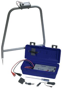
65 Troubleshooting Service Tools Wire Tracker Fault Finder Meter
66 Troubleshooting Service Tools s = Quantity X.7 s = Quantity X.7 s = Line Imbalance
67 Troubleshooting Service Tools s = 12 X.7 = 8.4 s = 12 X.7 = 8.4 s =.0 = Line Imbalance
68 Troubleshooting Service Tools s = 12 X.7 = 8.4 Wire Fault s = 73.6 Wire Fault s = 65.2 = Line Imbalance
69 Troubleshooting Wiring Faults No Wire Fault Wire Fault (Nicked Wire) Wire Fault (Open Wire)
70 Troubleshooting Wiring Faults No Wire Fault Voltage = 39 VAC / = 28.0 (40 x.7) Voltage = 39 VAC / = 28.0 (40 x.7) Wire Fault (Nicked Wire) Voltage = 21 VAC / = 28.0 (40 x.7) Voltage = 36 VAC / = (40 x.7) Wire Fault (Open Wire) Voltage = 0 VAC / = 0 (40 x.7) Voltage = 39 VAC / = 0 (40 x.7)
71 Troubleshooting Wiring Faults
72 38 #6. Wiring Troubleshooting Determine milliamp readings for: (each module.7 MA except as noted) #5. #4. #3. #2. #1. Worksheet #
73 38 #6. Wiring Troubleshooting Determine milliamp readings for: (each module.7 MA except as noted) , , , , , , #5. #4. #3. #2. #1. Worksheet #
74 38 #6. Wiring Troubleshooting Determine milliamp readings for: (each module.7 MA except as noted) #5. 78 #4. #3. #2. #1. Worksheet #


75 38 #6. Wiring Troubleshooting Determine milliamp readings for: (each module.7 MA except as noted) , , , , , , 38 #5. 78 #4. #3. #2. #1. Worksheet #
76 32 #4. Wiring Troubleshooting Determine milliamp readings for: (each module.7 MA except as noted) #3. #1. # Worksheet #3
77 32 #4. Wiring Troubleshooting Determine milliamp readings for: (each module.7 MA except as noted) , , , , #3. #1. # Worksheet #3
78 32 Wiring Troubleshooting Determine milliamp readings for: (each module.7 MA except as noted) #4. #5. #6. 36 #3. # # Worksheet #4

 1.")


79 32 Wiring Troubleshooting Determine milliamp readings for: (each module.7 MA except as noted) , , , , , , #4. #5. #6. 36 #3. # # Worksheet #4
80 # Wiring Troubleshooting Determine milliamp readings for: (each module.7 MA except as noted) #5. #2. Worksheet #5 #6. #4. #3.
 1.")

81 # Wiring Troubleshooting Determine milliamp readings for: (each module.7 MA except as noted) , , , , , , 186 #5. #2. Worksheet #5 #6. #4. #3.
82 Wiring Troubleshooting Determine milliamp readings for: (each module.7 MA except as noted) #6. 3 S #1. G #5. #4. Worksheet #6 # S G #2.
83 Wiring Troubleshooting Determine milliamp readings for: (each module.7 MA except as noted) , 40 (28 MA) , , 19 (13 MA) , , , , 4 #6. 3 S #1. G #5. #4. Worksheet #6 # S G #2.
84 Wiring Troubleshooting Wire Fault Troubleshooting Sequence 1. Measure Volts & 2. Disconnect Wire Splice at Isolation Connect In Wire to Each Out 1 to Measure 7. Measure on Each Wire as Required to Isolate Wire Fault 3 #1. G S #6. Wire Fault #5. #4. 3 S Worksheet #7 #2. G #3.

85 Wiring Troubleshooting Wire Fault Troubleshooting Sequence 1. Measure Volts & 2. Disconnect Wire Splice at Isolation Connect In Wire to Each Out 1 to1 3. 7, , Measure 7. Measure on Each Wire as Required to Isolate Wire Fault 3 #1. G S #6. Wire Fault #5. #4. 3 S Worksheet #7 #2. G #3.

86 Worksheet #8 Troubleshooting Field Communication Cable

87 Troubleshooting Field Communication Cable 3 S G 3 1 G Worksheet #9
88 Troubleshooting Field Communication Cable Worksheet #10 1. is Polarity Sensitive 2. Wire Path Voltage is VAC Amperage 1. Field Wiring is Specific to Board 2. Stations Max Per Wire 3. Stations Max Per Wire


89 Troubleshooting Field Communication Cable 1. Wiring is Polarity Sensitive 2. Wire Path Voltage is 40 VAC Amperage Maximum 1. Field Wiring is Specific to Daughter Board Stations Max Per Wire Stations Max Per Wire Worksheet #10
90 Golf Irrigation
Procedure Troubleshooting the Interconnect Cables
 Procedure 6.1 - Troubleshooting the Interconnect Cables Troubleshooting the upper interconnect cable 1. Remove the display housing per Procedure 7.13. Disconnect the upper interconnect cable from the upper
Aquavar SOLO 2 Frequently Asked Questions
 Aquavar SOLO 2 Frequently Asked Questions How do I size the Aquavar SOLO 2 for the appropriate pump/motor combination? Can I use a 208 Volt motor? Can I run the Aquavar SOLO 2 up to 80HZ? What are the
Baseline Two-Wire Technology
 Baseline Two-Wire Technology Baseline s bicoders work with Baseline s biline two-wire technology to create the only true bi-direc onal two-wire devices in the industry. Baseline s bicoders not only receive
Stand-Alone Bubble Detection System
 Instruction Sheet P/N Stand-Alone Bubble Detection System 1. Introduction The Bubble Detection system is designed to detect air-bubble induced gaps in a bead of material as it is being dispensed. When
AE R1 February 2015
 February 2015 CoreSense Diagnostics for Copeland Scroll UltraTech Air Conditioning Compressors TABLE OF CONTENTS Safety Safety Instructions... 2 Safety Icon Explanation... 2 Instructions Pertaining to
97C COMPRESSOR KIT 12V PART NO C COMPRESSOR KIT 24V PART NO C COMPRESSOR KIT PART NO
 97C COMPRESSOR KIT 12V PART NO. 00097 97C COMPRESSOR KIT 24V PART NO. 02497 98C COMPRESSOR KIT PART NO. 00098 97C 98C IMPORTANT: It is essential that you and any other operator of this product read and
Installation, use and maintenance instructions. Gas burner (5)
") Installation, use and maintenance instructions Gas burner MODEL GAS 4 TYPE 516 T80 291 (5) TECHNICAL FEATURES Thermal output 180-470 kw 154.800-404.200 kcal/h Fuel Natural gas Pci 8-10 kwh/m 3 = 7000-8600
Installation, use and maintenance instructions Gas burner MODEL GAS 4 TYPE 516 T80 291 (5) TECHNICAL FEATURES Thermal output 180-470 kw 154.800-404.200 kcal/h Fuel Natural gas Pci 8-10 kwh/m 3 = 7000-8600
POWERTRAIN CONTROL MODULE PIN IDENTIFICATION & VOLTAGE CHARTS > AXIOM 3.5L, PASSPORT, RODEO & RODEO SPORT 3.2L
 ENGINE CONTROLS - PIN VOLTAGE CHARTS INTRODUCTION 2002 Isuzu Axiom 3.5L Eng Base Pin voltage (value) charts are used for diagnosing intermittent symptoms and faults that are unable to be resolved during
BRILLIANT WONDERS LED BUBBLERS INSTALLATION INSTRUCTIONS & PRODUCT MANUAL CMP SERIES
 BRILLIANT WONDERS LED BUBBLERS INSTALLATION INSTRUCTIONS & PRODUCT MANUAL CMP 25503 SERIES TABLE OF CONTENTS A. PRODUCT OVERVIEW A.1 SPECIFICATIONS A. PRODUCT OVERVIEW... 3 A.1 Specifications A.2 Packing
COMPRESSOR PACK SUCTION CONTROLLER TYPE: LP41x
 Electrical Installation Requirements Care should be taken to separate the power and signal cables to prevent electrical interference and possible damage due to inadvertent connection. SUPPLY E L N LN2
Evaporative Emissions (EVAP) system, checking
 system, checking") Page 1 of 12 24-136 Evaporative Emissions (EVAP) system, checking CAUTION! Whenever carrying out work on the fuel supply and/or fuel injection systems, read and carefully follow the Cautions, Warnings,
Page 1 of 12 24-136 Evaporative Emissions (EVAP) system, checking CAUTION! Whenever carrying out work on the fuel supply and/or fuel injection systems, read and carefully follow the Cautions, Warnings,
444C DUAL PERFORMANCE VALUE PACK
 (Chrome) PART NO. 44432 IMPORTANT: It is essential that you and any other operator of this product read and understand the contents of this manual before installing and using this product. SAVE THIS MANUAL
Rain Bird IC System. The easiest path to world-class conditions. Elite courses like Pebble Beach Golf Links have discovered the power of IC Systems.
 Rain Bird IC System Elite courses like Pebble Beach Golf Links have discovered the power of IC Systems. Pebble Beach Golf Links Hole 8. Photo by Evan Schiller. The easiest path to world-class conditions.
BUBBLER CONTROL SYSTEM
 BUBBLER CONTROL SYSTEM Description: The LDBCS is a fully automatic bubbler system, which does liquid level measurements in water and wastewater applications. It is a dual air compressor system with, air
A i r c r a f t E l e c t r i c a l S y s t e m s ( 1 2 B )
") 8 5 4 9 A i r c r a f t E l e c t r i c a l S y s t e m s ( 1 2 B ) 40S/40E/40M An Aviation and Aerospace Technologies Course 8 5 4 9 : A i r c r a f t E l e c t r i c a l S y s t e m s ( 1 2 B ) 4 0
8 5 4 9 A i r c r a f t E l e c t r i c a l S y s t e m s ( 1 2 B ) 40S/40E/40M An Aviation and Aerospace Technologies Course 8 5 4 9 : A i r c r a f t E l e c t r i c a l S y s t e m s ( 1 2 B ) 4 0
Flow Sensors & Hydrometers Specification Sheet
 Baseline Flow s and Hydrometers Baseline s smart flow sensors and hydrometers are two-wire ready flow measurement and control devices that are pre-programmed with the correct K and Offset values. In addition,
AutoChanger Installation & User Guide Issue 2
 1 INDEX Page 1. Introduction... 3 2. AutoChanger Components Guide 4 3. Installation. 5-11 a) Installation Guidelines.. 5 b) Installation Retrofit... 6-11 c) Installation New... 11 4. AutoChanger User Guide
frequently asked questions
 Hydra Pilot Fault Codes What do the fault codes for the Hydra Pilot mean? Fault Cause FAULT 100 FAULT 101 FAULT 102 FAULT 103 FAULT 104 FAULT 105 FAULT 106 FAULT 108 FAULT 109 FAULT 110 FAULT 111 FAULT
400C & 450C DUAL PERFORMANCE VALUE PACKS
 (Chrome) PART NO. 40013 (Silver) PART NO. 45012 (Chrome) PART NO. 45013 IMPORTANT: It is essential that you and any other operator of this product read and understand the contents of this manual before
NGP-250/500 Nitrogen Generator Quick Start Guide
 NGP-250/500 Nitrogen Generator Quick Start Guide Version: A July 2013 Potter Electric Signal Company, LLC 5757 Phantom Dr., Suite 125 P. O. Box 42037 Hazelwood, MO 63042 Phone: (314) 595-6900 Document
Maintaining electrical equipment/systems
 Unit 037 Maintaining electrical equipment/systems Level: 2 Credit value: 15 NDAQ number: 500/9514/6 Unit aim This unit covers the skills and knowledge needed to prove the competences required to cover
SPECIFICATIONS ATTENTION
 VPS 504 S06 Installation Manual - P/N 80122 - Ed. 01/09 VPS 504 S06 and S05 Valve Proving System Installation Instructions VPS 1 6 Gases Natural gas, air and other inert gases. NOT suitable for butane
Steven Bellamy and Ronnie Jones Raleigh Durham International Airport
 Steven Bellamy and Ronnie Jones Raleigh Durham International Airport The Purpose of this Presentation 1. To introduce airfield lighting maintenance. 2. To collaborate and exchange information. The Classroom
WPB 5 / 7 / 10 INSTALLATION, OPERATION, & MAINTENANCE
 PACIFIC LIQUID & AIR SYSTEMS WPB 5 / 7 / 10 INSTALLATION, OPERATION, & MAINTENANCE IN THE BEGINNING Before installing or operating this system, familiarize yourself with these instructions. You should
BUBBLER CONTROL SYSTEM
 BUBBLER CONTROL SYSTEM Description: The HDBCS is a fully automatic bubbler system, which does liquid level measurements in water and wastewater applications. It is a dual air compressor system with, air
200 PSI COMPRESSORS - MODEL NUMBERS
 200 PSI COMPRESSORS - MODEL NUMBERS 380C AIR COMPRESSOR KIT PART NO. 38033 480C AIR COMPRESSOR KIT PART NO. 48043 380C 480C IMPORTANT: It is essential that you and any other operator of this product read
100C Air Compressor Kit
 10010 100C Air Compressor (standard mounting bracket, CE Spec) 10014 100C Air Compressor (no leader hose or check valve, CE Spec) 10016 100C Air Compressor (with Omega Bracket, CE Spec) IMPORTANT: It is
SonoMeter 30 Energy Meters
 Data Sheet SonoMeter 30 Energy Meters Description The Danfoss SonoMeter 30 is a range of ultrasonic, compact energy meters intended for measuring energy consumption in heating and cooling applications
400H HARDMOUNT AIR COMPRESSOR KIT PART NO H HARDMOUNT AIR COMPRESSOR KIT PART NO
 400H HARDMOUNT AIR COMPRESSOR KIT PART NO. 40042 450H HARDMOUNT AIR COMPRESSOR KIT PART NO. 45042 400H 450H IMPORTANT: It is essential that you and any other operator of this product read and understand
OPERATION & INSTALLATION INSTRUCTIONS
 Reliable Golf Course Supplies Rev. A 6/30/98 OPERATION & INSTALLATION INSTRUCTIONS Congratulations on your purchase of Reliable Golf Course Supplies Tee Sentry. Your shipment should include the following
Flamco Flamco-Fill STA Flamco-Fill STM
 STA STM Typ STA 5936 Typ STM 5937 GB Installation and operating instructions 1999, 2 Contents GB UK Limited P.O. Box 9, Washway Lane, St. Helens, Merseyside WA10 6FE United Kingdom Telephone: 01744 744744
Aqua Control, Inc. 60Hz. BOTTOM CIRCULATOR INSTRUCTION MANUAL TABLE OF CONTENTS
 Aqua Control, Inc. 60Hz. BOTTOM CIRCULATOR INSTRUCTION MANUAL TABLE OF CONTENTS PAGE PAGE Safety 1 Anchoring Anchoring Instructions 6 Installation / Launching Floating of the Bottom Circulator 2 Sinking
https://w05.dealerconnect.chrysler.com/service/mds2002/serviceinfo/en_us/81689ac0.htm... *ACTUATOR CIRCUIT TEST DIAGNOSTICS (DUAL-ZONE)
") Page 1 of 14 *ACTUATOR CIRCUIT TEST DIAGNOSTICS (DUAL-ZONE) Page 2 of 14 For a complete wiring diagram Refer to Section 8W. Theory of Operation By running the Actuator Circuit Test, the A/C Heater Control
Page 1 of 14 *ACTUATOR CIRCUIT TEST DIAGNOSTICS (DUAL-ZONE) Page 2 of 14 For a complete wiring diagram Refer to Section 8W. Theory of Operation By running the Actuator Circuit Test, the A/C Heater Control
TWC Services, Inc. Structured On-The-Job Training for JT- 1, 2, 3
 TWC Services, Inc. Structured On-The-Job Training for JT- 1, 2, 3 The following tasks parallel the Jr. Tech (JT-1, 2, 3) description and development plan and use the Refrigeration and Air conditioning
PURGEX X Purge Controller E Version. User s Manual
 PURGEX X Purge Controller E Version User s Manual This page intentionally left blank Information in this document is subject to change without notice. All terms mentioned in this manual that are known
OEM Manual. MODEL ½ Digit DRUM SCALE
 OEM Manual MODEL 4020-3 ½ Digit DRUM SCALE Scaletron Industries, Ltd. Bedminster Industrial Park 53 Apple Tree Lane P.O. Box 365 Plumsteadville, PA 18949 USA Toll Free: 1-800-257-5911 (USA & Canada) Phone:
IMPORTANT SAFETY INSTRUCTIONS
 IMPORTANT SAFETY INSTRUCTIONS CAUTION - To reduce risk of electrical shock: - Do not disassemble. Do not attempt repairs or modifications. Refer to qualified service agencies for all service and repairs.
420C AIR COMPRESSOR KIT PART NO C AIR COMPRESSOR KIT PART NO
 420C AIR COMPRESSOR KIT PART NO. 42042 460C AIR COMPRESSOR KIT PART NO. 46043 420C 460C IMPORTANT: It is essential that you and any other operator of this product read and understand the contents of this
PurgEx. X Purge Controller N Version. User s Manual
 PurgEx X Purge Controller N Version User s Manual This page intentionally left blank Information in this document is subject to change without notice. All terms mentioned in this manual that are known
42045 Heavy Duty ADA Base Model Kit: 85/105 PSI (ADA Compressor Only) Heavy Duty ADA Base Model Kit: 110/145 PSI (ADA Compressor Only)
 Heavy Duty ADA Base Model Kit: 110/145 PSI (ADA Compressor Only)") 42045 Heavy Duty ADA Base Model Kit: 85/105 PSI (ADA Compressor Only) 42047 Heavy Duty ADA Base Model Kit: 110/145 PSI (ADA Compressor Only) 45052 Constant Duty ADA Base Model Kit: 85/105 PSI (ADA Compressor
42045 Heavy Duty ADA Base Model Kit: 85/105 PSI (ADA Compressor Only) 42047 Heavy Duty ADA Base Model Kit: 110/145 PSI (ADA Compressor Only) 45052 Constant Duty ADA Base Model Kit: 85/105 PSI (ADA Compressor
LENNOX SLP98UHV DIAGNOSTIC CODES
 Code Status of Equipment Action required to clear and recover - Idle mode (Decimal blinks at 1 Hertz -- 0.5 second ON, 0.5 second OFF) A Cubic feet per minute (cfm) setting for indoor blower (1 second
Model 106 DPI "Micro-switch" Installation and Operating Instructions
 Mid-West Instrument Model 106 DPI "Micro-switch" Installation and Operating Instructions BULLETIN NO. IM116DPImicro/09A Replaces --- INSPECTION Before installation carefully check the Model Number on each
250C-IG COMPRESSOR KIT 12V PART NO C-IG COMPRESSOR KIT 24V PART NO
 250C-IG COMPRESSOR KIT 12V PART NO. 25050 250C-IG COMPRESSOR KIT 24V PART NO. 25058 IMPORTANT: It is essential that you and any other operator of this product read and understand the contents of this manual
RPS900W Redundant Power Supply. Installation Guide.
 RPS900W Redundant Power Supply Installation Guide www.edge-core.com Installation Guide RPS900W Redundant Power Supply Single DC Output Port with Dual Output Voltages RPS900W E10013-CS-R01 1500000081A
Transmitter CS 21 Operation Manual
 Transmitter CS 21 Operation Manual 1194 Oak Valley Drive, Suite 20, Ann Arbor, MI 48108 800-959-0573 734-769-1888 Content Page For your Safety 3 General Description 3 Detection Principle 4 Operation 4
250C-IG COMPRESSOR KIT 12V PART NO C-IG COMPRESSOR KIT 24V PART NO
 250C-IG COMPRESSOR KIT 12V PART NO. 25050 250C-IG COMPRESSOR KIT 24V PART NO. 25058 IMPORTANT: It is essential that you and any other operator of this product read and understand the contents of this manual
QPEO2/037N Credit Value: 15 QCF Level: 2 GLH: 68 Maintaining electrical equipment/systems
 Performing Engineering Operations QPEO2/037N Credit Value: 15 QCF Level: 2 GLH: 68 Maintaining electrical equipment/systems Learner Name: 2013 Excellence, Achievement & Learning Ltd EAL Assessment Route
TANDEM MODULATOR FOR OUTLET GAS FLOW: STEPPED (836 TANDEM) - CONTINUOUS (837 TANDEM) SERVO-CONTROLLED PRESSURE REGULATOR
 - CONTINUOUS (837 TANDEM) SERVO-CONTROLLED PRESSURE REGULATOR") SIT Group 836-837 TANDEM MULTIFUNCTIONAL GAS CONTROL MODULATOR FOR OUTLET GAS FLOW: STEPPED (836 TANDEM) - CONTINUOUS (837 TANDEM) SERVO-CONTROLLED PRESSURE REGULATOR ALL ADJUSTMENTS ACCESSIBLE FROM ABOVE
SIT Group 836-837 TANDEM MULTIFUNCTIONAL GAS CONTROL MODULATOR FOR OUTLET GAS FLOW: STEPPED (836 TANDEM) - CONTINUOUS (837 TANDEM) SERVO-CONTROLLED PRESSURE REGULATOR ALL ADJUSTMENTS ACCESSIBLE FROM ABOVE
200 PSI HIGH-FLOW AIR SOURCE KIT
 200 PSI HIGH-FLOW AIR SOURCE KIT 50% Duty Compressor on 2.0 Gallon Air Tank PART NO. 20008 IMPORTANT: It is essential that you and any other operator of this product read and understand the contents of
200 PSI FAST-FILL AIR SOURCE KIT
 200 PSI FAST-FILL AIR SOURCE KIT 55% Duty Compressor on 2.0 Gallon Air Tank PART NO. 20007 IMPORTANT: It is essential that you and any other operator of this product read and understand the contents of
MODEL 6600 Rev. B4 USER'S MANUAL LAVERSAB INC., 505 GILLINGHAM LANE. SUGAR LAND TX (281) FAX: (281)
 FAX: (281)") MODEL 6600 Rev. B4 USER'S MANUAL LAVERSAB INC., 505 GILLINGHAM LANE. SUGAR LAND TX 77478 (281) 325-8300 FAX: (281) 325-8399 Email: aservice@laversab.com Document Number : 9051 REV B4 Date: June 07, 2011.
MODEL 6600 Rev. B4 USER'S MANUAL LAVERSAB INC., 505 GILLINGHAM LANE. SUGAR LAND TX 77478 (281) 325-8300 FAX: (281) 325-8399 Email: aservice@laversab.com Document Number : 9051 REV B4 Date: June 07, 2011.
GAS FUEL VALVE FORM AGV5 OM 8-03
 ALTRONIC AGV5 OPERATING MANUAL GAS FUEL VALVE FORM AGV5 OM 8-03 WARNING: DEVIATION FROM THESE INSTALLATION INSTRUCTIONS MAY LEAD TO IMPROPER ENGINE OPERATION WHICH COULD CAUSE PERSONAL INJURY TO OPERATORS
Transmitter CS 21 Operation Manual
 Transmitter CS 21 Operation Manual Content Page For your Safety 3 General Description 3 Detection Principle 4 Operational Notes 4 Design 4 Mounting Position of CS21 5 Mounting 6 Installation of Electrical
TR Electronic Pressure Regulator. User s Manual
 TR Electronic Pressure Regulator Page 2 of 13 Table of Contents Warnings, Cautions & Notices... 3 Factory Default Setting... 4 Quick Start Procedure... 5 Configuration Tab... 8 Setup Tab... 9 Internal
Covered Task 409OP Training Guide Inspecting Interference Bonds
 Directions This training guide is to be used by a Subject matter expert (SME) authorized Evaluator/Trainer and Trainee during on-thejob training (OJT) or prior to an evaluation as a resource. (S) Indicates
OPERATING INSTRUCTIONS Pressure Control System PCS-20 through PCS-100
 107 W. Main Street Worthington, PA 16262 Phone: 724.297.3416 Fax: 724.297.5189 http://www.airtak.com OPERATING INSTRUCTIONS Pressure Control System PCS-20 through PCS-100 12-2007 TABLE OF CONTENTS PAGE
CDS-2000 CO 2 Sensor Verification, Calibration, and Troubleshooting Bulletin
 Electronic Control Manual 216 Sensors and Stats Section S Technical Bulletin CDS-2000 Issue Date 0393 CDS-2000 CO 2 Sensor Verification, Calibration, and Troubleshooting Bulletin Introduction 3 Pre-Verification
Gas Network Craftsperson
 Gas Network Craftsperson Unit EIAU016 Carrying out Fault Diagnosis on Electrical Equipment and Circuits This assessment specification has been developed as part of the network maintenance craftsperson
MARATHON SENSORS INC. TROUBLESHOOTING A CARBON PROBE
 When there is a problem making consistent product in a carborizing furnace you must consider all the possibilities before replacing the oxygen sensor. In many cases using the sensor and the control instrument
SVEA II GSM Connector User Manual
 www.possio.com SVEA II GSM Connector User Manual 1. Introduction Before using SVEA II please read this manual carefully and keep it for future reference. SVEA II GSM Connector is a device for realization
AUTO PUMP STATUS CENTER
 INSTRUCTION MANUAL AUTO PUMP STATUS CENTER PRESSURE ONLY MODEL #: 091-198-12-AP File: IM_091-198-12-AP_revD.indd Rev: D, pg 3 WD Revised By: PSS Date: 2-01-2016 3 YEAR WARRANTY INTRODUCTION The Auto Pump
Universal Valve Company Inc
 Universal Valve Company Inc 800-223-0741 www.universalvalve.com 1975-FA34 (Air Tower Troubleshooting Manual) Overview This manual has been arranged as a tool for diagnosing, and repairing Free Air Universal
Additions, Revisions, or Updates
 1 3 01-12 SUBJECT DATE SPN 4334/FMI 2, 3, 4, 7 and SPN 4375/FMI 6 February 2012 Additions, Revisions, or Updates Publication Number / Title Platform Section Title Change SPN 4334/FMI 2 DDC-SVC-MAN-0084
AcornVac Vacuum Plumbing Systems - Trouble Shooting Guide
 AcornVac Vacuum Plumbing Systems - Trouble Shooting Guide 1. Accumulators Problem Accumulator is overflowing If Accumulator continues to overflow Correction 1. Push and hold the manual activation button
User Manual for Amron International Diving Supply, Inc.
 User Manual for Amron International Diving Supply, Inc. Model 2810E and 2810E-1 One Diver Communicator S/N This manual and the information contained herein are provided for use as an operation and maintenance
Connect with Confidence NO POWER NO PROBLEM
 Connect with Confidence NO POWER NO PROBLEM The ideal solution to implement wireless sensor monitoring in IoT applications where power is not available. At last, there s a roll-out ready way to implement
11/2/2017. Course Objectives. Overview
 Course Objectives The objective of this CBT module is to insure that personnel receive basic training in electrical safety. Every employee's work involves electricity. This may vary from typical electrical
BRILLIANT WONDERS LED BUBBLERS INSTALLATION INSTRUCTIONS CMP SERIES. Brilliant Wonders LED BUBBLERS
 R BRILLIANT WONDERS LED BUBBLERS INSTALLATION INSTRUCTIONS CMP 25503 SERIES Brilliant Wonders LED BUBBLERS TABLE OF CONTENTS 1. Product Overview....3 1.1 Specifications. 3 1.2 Packing List...3 2. System
NIV EAU MATIC ST User Manual Made in Canada
 NIV EAU MATIC ST User Manual Made in Canada www.niveaumatic.com info@niveaumatic.com -2- Table of contents Introduction Section 1 Page 4 Installation Section 2 Pages 5 to 10 2.1 Control box 2.2 Sensor
The Proper Procedure
 The Proper Procedure Lockout Lockout is used to prevent the release of hazardous energy or equipment from starting by applying a lockout device and lock A padlock is placed on the appropriate energy isolating
MODEL NUMBER: PSI AIR SOURCE KIT 200 PSI Compressor on 2.0 Gallon 200 PSI Air Tank
 IMPORTANT SAFETY INSTRUCTIONS CAUTION - To reduce risk of electrical shock or Electrocution: MODEL NUMBER: 20008 200 PSI AIR SOURCE KIT 200 PSI Compressor on 2.0 Gallon 200 PSI Air Tank IMPORTANT: It is
MODEL NUMBER: M20005 AIR SOURCE KIT. 30% Duty Compressor on. 2.0 Gallon Air Tank SAVE THIS MANUAL FOR FUTURE REFERENCE
 MODEL NUMBER: M20005 AIR SOURCE KIT 30% Duty Compressor on 2.0 Gallon Air Tank SAVE THIS MANUAL FOR FUTURE REFERENCE USER MANUAL IMPORTANT SAFETY INSTRUCTIONS CAUTION - To reduce risk of electrical shock
480C DUAL PERFORMANCE VALUE PACK
 (Pewter) PART NO. 48012 (Chrome) PART NO. 48032 (Stealth Black) PART NO. 48042 IMPORTANT: It is essential that you and any other operator of this product read and understand the contents of this manual
FLUID POWER FLUID POWER EQUIPMENT TUTORIAL ACCUMULATORS. This work covers part of outcome 2 of the Edexcel standard module:
 FLUID POWER FLUID POWER EQUIPMENT TUTORIAL ACCUMULATORS This work covers part of outcome 2 of the Edexcel standard module: UNIT 21746P APPLIED PNEUMATICS AND HYDRAULICS The material needed for outcome
Vacuum Pumpdown and Venting Procedure, CRaTER Thermal Vacuum System. Dwg. No
 Rev. ECO Description Checked Approval Date 01 32- Release M. Smith Vacuum Pumpdown and Venting Procedure, CRaTER Thermal Vacuum System Dwg. No. 32-06003.05 Revision 01 June 18, 2007 1 1. Introduction 1.1.
Operating instructions Safety Rope Emergency Stop Switches ZB0052 / ZB0053 ZB0072 / ZB0073
 Operating instructions Safety Rope Emergency Stop Switches UK ZB0052 / ZB0053 ZB0072 / ZB0073 7390878 / 02 03 / 2011 Contents 1 Safety instructions...3 2 Installation / set-up...4 2.1 Applications...4
JOLLY2. Installation user s manual. 6 different operating modes selectable. version 3.3. DATA TO BE FILLED OUT BY THE INSTALLER (Page 1)
") ENGLISH ENGLISH ENGLISH ENGLISH Installation user s manual Warning! electrical scheme modified JANUARY 2005 version 3.3 JOLLY2 DATA TO BE FILLED OUT BY THE INSTALLER (Page 1) 6 different operating modes
ENGLISH ENGLISH ENGLISH ENGLISH Installation user s manual Warning! electrical scheme modified JANUARY 2005 version 3.3 JOLLY2 DATA TO BE FILLED OUT BY THE INSTALLER (Page 1) 6 different operating modes
LED Tips & Tricks. PO Box 1949, Nelson 7040, New Zealand. Head Office, 53C Bolt Road, Nelson 7011, New Zealand
 LED Tips & Tricks Head Office, 53C Bolt Road, Nelson 7011, New Zealand PO Box 1949, Nelson 7040, New Zealand Phone +64 (3) 970 0755 Email sales@switch-lighting.co.nz Common Terms used in LED Lighting Term
IMPORTANT SAFETY INSTRUCTIONS
 IMPORTANT SAFETY INSTRUCTIONS CAUTION - To reduce risk of electrical shock or electrocution: - Do not disassemble. Do not attempt repairs or modifications. Refer to qualified service agencies for all service
VX Series Salt Chlorinator S Model
 VX Series Salt Chlorinator S l OPERATING INSTRUCTIONS HURLCON Manufacturing & sales Pty. Limited. A.B.N. 97 007 284 504 www.hurlcon.com.au service@hurlcon.com.au Information and specifications subject
Safety Manual: Hazardous Energy. January, 2017
 Safety Manual: Hazardous Energy January, 2017 9.0 Hazardous Energy Introduction Energized equipment in the workplace pose a significant risk of injury and death. If the unexpected energization or start-up
MODEL 269DF-LCF-LCF/WS FILLING SYSTEM
 MODEL 269DF-LCF-LCF/WS FILLING SYSTEM 29975 Parkway Roseville, Michigan 48066 (586) 778-0426 Fax (586) 778-0479 www.gordinier.com Email: pat@gordinier.com MODEL 269DF-LCF-LCF/WS TABLE OF CONTENTS Receiving
INNOVATIVE. POWERFUL. COMPLETE. THE ONLY ONE OF ITS KIND.
 IC System INNOVATIVE. POWERFUL. COMPLETE. THE ONLY ONE OF ITS KIND. Rain Bird IC System true, two way integrated control. Golf courses in over 50 countries around the world trust the proven performance
Copeland Discus with CoreSense Diagnostics January 2011
 Copeland Discus with CoreSense Diagnostics January 2011 Slide 1 1/27/2011 5:48 PM Discus with CoreSense Diagnostics Case Studies Supermarket In Columbus, Ohio Saves $4,500 With Discus with CoreSense Diagnostics
Marschalk Model # 94000
 Marschalk Model # 94000 12-volt DC Portable oil-less Air Compressor Operation Manual 27250006 REV 1 9/13/05 Table of Contents CHAPTER 1: SYSTEM DESCRIPTION... 5 FUNCTION AND THEORY... 5 SYSTEM COMPONENTS...
Additions, Revisions, or Updates
 1 2 06-11 SUBJECT DATE SPN 4375/FMI 6 DEF Pump Supply Current High February 2011 Additions, Revisions, or Updates Publication Number / Title Platform Section Title Change DDC-SVC-MAN-0084 EPA10 DD SPN
HEAT-TIMER CORP. 20 NEW DUTCH LANE FAIRFIELD, NEW JERSEY TEL. (973) FAX (973) INSTALLATION & OPERATION MANUAL TABLE OF CONTENTS
 FAX (973) INSTALLATION & OPERATION MANUAL TABLE OF CONTENTS") HEAT-TIMER CORP. 20 NEW DUTCH LANE FAIRFIELD, NEW JERSEY 07004 TEL. (973)575-4004 FAX (973)575-4052 INSTALLATION & OPERATION MANUAL MODEL MOD-4 TABLE OF CONTENTS Control Panel...2 MOD-4 Overview...4 Installation...6
HEAT-TIMER CORP. 20 NEW DUTCH LANE FAIRFIELD, NEW JERSEY 07004 TEL. (973)575-4004 FAX (973)575-4052 INSTALLATION & OPERATION MANUAL MODEL MOD-4 TABLE OF CONTENTS Control Panel...2 MOD-4 Overview...4 Installation...6
KGW - ISOTHERM. Operating Instructions. Level controlling device for liquid nitrogen LEVEL CONTROL LN2
 KGW - ISOTHERM Germany 76185 Karlsruhe Gablonzer Straße 6 Tel. 0049 / 721 / 95897-0 Fax. 0049 / 721 / 95897-77 email:info@kgw-isotherm.de Internet: www.kgw-isotherm.de Operating Instructions Level controlling
Unit 24: Applications of Pneumatics and Hydraulics
 Unit 24: Applications of Pneumatics and Hydraulics Unit code: J/601/1496 QCF level: 4 Credit value: 15 OUTCOME 2 TUTORIAL 9 ACCUMULATORS The material needed for outcome 2 is very extensive so there are
Miniature controls. Contactors. Overload relays. Starters. Control relays
 Contactors Overload relays Starters Control relays Description General features Wiring terminations available include plugon connectors, wire pins for PC board mounting and solder connections Low power
Gas Check. Short testing time, with automatic start-up if no leakage was detected from previous operation.
 Quality Products at Competitive Prices Gas Check Automatic testing of the down-stream installation to check that all valves are closed and that pipework and fittings are gas tight before each system start-up.
GATE 2 Part No
 PAGE 1 GATE 2 Part No. 23001125 SWING GATE CTROLLER INSTALLATI GUIDE Page 2 GATE 2 Code No. 23001125 Electronic Control Board for use with SEA Hydraulic or Electro-mechanical swing gate operators (without
DPC-30 DPC-100. Reference Manual
 DPC-30 DPC-100 Reference Manual 1. Introduction 1.1 Description The Martel DPC Digital Pneumatic Calibrator improves upon traditional dial gauge pneumatic calibrators. The Martel DPC improves accuracy,
VERTICAL AIR COMPRESSORS
 VERTICAL AIR COMPRESSORS MODEL NO: VE11C150, VE15C150, VE18C150 PART NO: 2226005, 2226000, 2226015 OPERATION & MAINTENANCE INSTRUCTIONS LS0615 INTRODUCTION Thank you for purchasing this CLARKE Vertical
Installation, Operation and Maintenance Instructions for Electronically Controlled Pressurisation Units
 Installation, Operation and Maintenance Instructions for Electronically Controlled Pressurisation Units Models: EPS Single Pump EPT Twin Pump EPS-HP EPT-HP Single Pump High Pressure Twin Pump High Pressure
PURGEX X Purge Controller D Version
 PURGEX X Purge Controller D Version User s Manual This page intentionally left blank Information in this document is subject to change without notice. All terms mentioned in this manual that are known
UBEC 1AT. AUTO TANK Fill System Installation, Operation, & Setup Instructions
 Document Number: XE-ATA5PM-R1A UBEC 1AT AUTO TANK Fill System 08899155 Installation, Operation, & Setup Instructions Rev170906-EB-FRC PHYSICAL: 1302 WEST BEARDSLEY AVE ELKHART, IN 46514 WWW.ELKHARTBRASS.COM
INSTRUCTION MANUAL. FLOW CONTROL DRAWERS MANUAL / PLC CONTROL SERIES Model Version Perma Pure LLC Tel:
 PERMA PURE INSTRUCTION MANUAL FLOW CONTROL DRAWERS MANUAL / PLC CONTROL SERIES Model 3300 Version 4.06 Perma Pure LLC Tel: 732-244-0010 P.O. Box 2105, 8 Executive Drive Tel: 800-337-3762 (toll free US)
sensazone sensazone is an intelligent PIR sensor operated system which controls the water supply and the light and fan functions in washrooms.
 sensazone installation guide 1 System requirements sensazone is an intelligent PIR sensor operated system which controls the water supply and the light and fan functions in washrooms. The system features
A4 Operation Manual. Fig.1-1 Controller Socket Diagram
 A4 Operation Manual Safety Instruction Please read this manual carefully, also with related manual for the machinery before use the controller. For installing and operating the controller properly and