Color GPS Mark III/AP
|
|
|
- Bernice Shaw
- 5 years ago
- Views:
Transcription

1 Color GPS Mark III/AP Nearby spot Touch ZONE Menu Touch ZONE AP touch zone Specifications Color 3.2 Inch display with LED backlight Touch sense operated Fast 32 RISC 48 MHz processor for high precision calculations Can be used all over the World 200 memory locations for storing of spots Home function Boat battery monitoring with alarm (7-13 volts) Display battery monitoring with alarm Zone alarm selectable 5,10,20,40 meters Steering with flagged marker and left/right indicators Auto zoom Radio link distance 1000 meters on ISM band MHz (sub band 6) license free to use in whole Europe using FHSS Long Range duplex! Transmitter output power 50 mw (+17 dam) 1

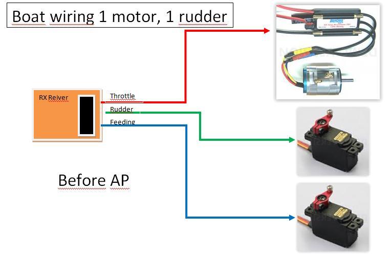
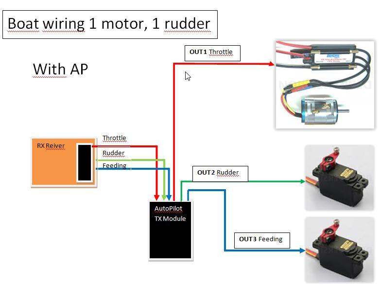
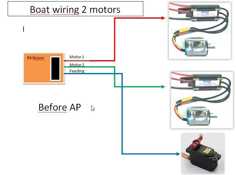
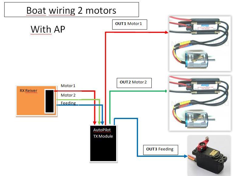
2 Receiver display can be bind to TX with unique ident Fast update of position 2x second! Built in battery 4.8volt LiMH 2700ma, chargeable via cord from volt battery or mains adaptor Maximum plot range 999 meters Ublox Neo6 next generation GPS receiver maximum 60 satellites tracking Accuracy Position 5 meters 2D-RMS 1 meters 2D RMS WAAS Current consumption transmitter (boat site) 90 ma (0.09Amp) Current consumption Display 120ma (aprox hours of operation with 2700 ma battery s without charging AP included in software (option), suitable for boat systems 1 motor/ 1 rudder 2 motors boat, 1 nozzle/jet boat Max range of AP 999 meters, accuracy of arriving to selected spot within 1 meters Failsafe build in: max range/blocking by obstructions/rf link failures Easy setup of AP, using simplified menus Automatic feeding at selected spot Calculates track with 10 GPS updates/seconds! TX can be powered from RC RX 2
3 With this ColorGPS locator you will be able to refind your way to previous stored spots. The transmitter module is located in the bait boat powered by the boat s battery. A tuned small antenna of 10 cm and high power transmitter module gives you a range of aprox 500 meters, far beyond the point you will be able to identify with your bait boat. The software can be extended (option) with an Autopilot to obtain automatically steering to the selected spot. After loading your pre stored spot, you will see in the plotting screen: The distance to the spot (in meters) Heading to steer, a flag ahead of you gives you the indication how to steer. 2 arrows for steeringdirection left and right The boats actual speed in km/hours Information about the actual number of satellites insight, 3D or 2D. The altitude of you current location The battery of the display indication: Blue/Yellow or RED/White when the voltage dropped below 4.5 volts a warning alert will be given The actual latitude longitude position of the bait boat (in decimal degrees) The actual voltage of your bait boat battery. In case when the voltage drops down a certain level this will be indicated in RED/WHITE and an alert will be given. Actual local time with automatic daylight saving adjustment (summer/wintertime) Note: the time is fixed on west central Europe (+1 hour). In other parts of the world you will get an offset due the fact that the GPS satellite is transmitting UTC time. HOME indication that the departure location has be stored. This will help you to find your back to the shore. RF field indication, showing the received signal strength 3

4 Inhoud EXAMPLES... 4 Home function... 7 Autopilot... 7 Failsafe autopilot... 9 Basic Menu Saving a spot Loading a Spot Modifying Latitude/Longitude Manual Inserting Latitude/Longitude from Google Earth Nearby Spots TOOLS Factory Settings Calibration of the Touch panel Erase all data Binding the GPS display to the TX module Charging the batteries Hooking up the AP Calibration of the RC Adjustment of the PidController Rudder Adjustment of Motor gain and Motor Integrator factor EXAMPLES The boat is 69 meters away from the spot, scale 100 meters. You will get the flag to indicate the direction to steer. In this case the spot is a little to the left, so steer a little to the left to get back on track. 4


5 The spot is far behind you, you need to turn around The boat is drifting away from the spot; make a strong turn to the left. The arrow is indicating left When the boat comes closer to the spot: The flag become a circle this circle will become bigger the more you come in range of the spot. -indicating you almost there. In this case the spot is more to the left, so steer the boat to the left 5

.")
6 In this case the boat has almost arrived at the spot (scale 25 meters), but a bit to the right, so steer to the right to get on the spot. (Slow speed!!!) The spot is behind the bait boat but on the right side. Steer to the right to turn the boat around. (Slow speed!!). Here we are arrived exactly on the spot; the circle is wrapped around the triangle. Start fishing! 6

7 Home function The moment you power on the display, the actual GPS location will be stored in a volatile memory. Only in case there a more then 4 satellites! So first always power your boat on, wait until the GPS has captured the first 5 satellites. Then switch the display off, and switch it on again. The position is stored. Then you can enter the desired spot when there is no spot just go. To refind your way back to the shore, just simply hit the HOME icon, as showed in the example. After you have touched the home zone, the name of the spot will change to HOME. None of your stored spots will be erased; this is only an indication that your HOME location has been loaded. Autopilot The GPS has a build in autopilot, capable to steer the boat within 1 meter range of the selected spot. To operate the autopilot follow the indicated steps. 1. First select a spot, this spot has to be within the range of 999 meters of the start position, see also failsafe autopilot. 2. Be sure you got at least 6 satellites, best performance will be with 10 sats or more 3. Open the autopilot menu by clicking in the left-down corner of the main screen. 4. Arm the autopilot by clicking on the AP-OFF icon to AP ON. (figure 2) 5. Select which feeder bay (1 or 2) has to be used. In case of only 1 feeder container user Feeder Close this menu 7


8 7. Be sure that you have the gpsdisplay with the antenna upwards and at least 1 meter above the ground. The range will be significantly decreased when the gps display is lying on the ground. The gps display has to keep contact with the boat during the trip, otherwise the failsafe will become active and the boat will return! 8. Steer the boat manually full throttle in the direction of the spot for at least 5 seconds. The autopilot will be switched on after 5 seconds, a bell sound fill be given on the GPS display, and in the left in the display the sign AP will be painted. Release the throttle stick to neutral as soon you hear the gps active bell sound. Always steer the boat in a free direction. The autopilot has to settle during the first seconds and thus making large turns. Never steer the boat towards shore site, always towards a free area. Remember the autopilot will make a straight line to the spot, any obstruction between start point and waypoint will block the boat. 9. To disable the autopilot, give FULL reverse throttle for at least 1 second. The AP arming will also be disabled. If you want to enable the AP again, repeat steps from point 3 1 8


9 Figure 2 In case the TX-calibration warning is given, it means the AP cannot operate before it has been calibrated! The Boatspeedmenu is used to specify the cruise speed of the bait boat. To change the speed click on the line and a menu will be open to input a new speed. Note: the speed regulation is depending on the settings in the AP settings menu. The boat speed will be depending mainly on the full stick position given at the start, and will be throttled to the specified speed. Failsafe autopilot To insure that in case of some error the boat will stop of return to base some features has been added into the autopilot. 9
10 1) The maximum range the autopilot can operate is 999 meters from the start point. In autopilot mode the boat will stop when the distance is more than 999 meters from start point. 2) In case the duplex link between the GPS display and TX module has been interrupted for more than 30 seconds, the boat will return to the start point so called failsafe. 3) The failsafe doesn t work if the boat is in the range of 20 meters of the start point. 4) The start point is activated/stored the moment that the autopilot was armed and has given 5 seconds full throttle. This will say that the failsafe will never become active if the boat wasn t operated in the autopilot mode! In other words: the failsafe won t become active in manual mode (no ap used). 5) If the boat is blocked by some obstructions, the motor(s) will cut off after 15 seconds. Therefore the slowest cruise speed cannot be lower than 1.5 km/h this to avoid this failsafe to become active. This is not active in the manual mode! Basic Menu This menu can be reached by touching the central area of the standard plotting display (see example) 10

11 Here you can access the sub-menu for storing the actual spot A shortlist of near-by located spots (max 5) Or load a pre stored spot (or edit a preloaded spot) Adjustments (tools) access Switching between high-medium and low energy mode. High energy will give a bright display, but also uses a lot more current from the batteries. Low energy will give a dimmed display, for use in the night this is perfect, and you will save the batteries. 11


12 Saving a spot In this submenu you can store the actual spot. To do so, only hit the Save Icon You will get a confirmation screen after saving. Any time you can go back by touching the Back Icon In case you want to change the spot s name, simply touch the marker name in this example P2. A keyboard screen will come up. After 12
13 closing this keyboard screen, you will be returned to this Save Menu to save the spot. Note: you can always change afterwards the name of the spot. Note: in case there a too less satellites, the Store Menu is not available. An indication will be given that you have to wait for more satellites, this to avoid inaccuracy of the location. To modify the name of the marker simply touch several times on DELETE then type (touch) in the keyboard the new name (max 18 chars). To save your modified spot name touch on ENTER Icon Any time you can go back by touching the BACK Icon For Upper/lower chars touch on caps field. For Upper Chars this field will be showed as CAPS, for lower chars the fields is presented as caps. 13


14 Loading a Spot In this submenu you can see the datum/time of a previous stored spot. Also the latitude/longitude is given.+distance to the actual boat position Note: the latitude and longitude is in decimal format. Walk through all you stored spots by selecting the right bar. Scrolling in steps of 5 by the up/down touch zones. Select a spot (for loading as actual spot) touch the Load Icon (disk) 14
 and the keyboard will come up.")
15 Erasing of a spot: touch the Erase icon a screen will come up for confirmation of the action. Anytime you go back to the plotting screen by touching the left Back icon To change the name of the spot, simply touch the Marker name (in this example P3) and the keyboard will come up. To modify the name of the marker simply touch several times on DELETE then type (touch) in the keyboard the new name (max 18 chars). To save your modified spot name touch on ENTER field Any time you can go back by touching the BACK field For Upper/lower chars touch on caps field. For Upper Chars this field will be showed as CAPS, for lower chars the fields is presented as caps. Modifying Latitude/Longitude Manual Inserting Latitude/Longitude from Google Earth 15

16 In this example 4 spots are predefined by looking up their position in Google Earth. Using the Decimal degree option from Google Earth the spots can be entered so the user can steer the boat right away to this spot. An accuracy of 1 meter can be obtained, when all digits are entered. Don t forget to insert N, S, W, and E before the number so the GPS know what quadrant of the globe you are talking about. (For Europe this is Nord and East. For UK this might be E or W, and North First save some spots from the GPS (doesn t matter which spot, as long you save one. Modify the spot name, and after that touch the latitude or longitude row. A new screen will open where the lat/long can be modified 16

17 Delete the old latitude or longitude by pressing the C key, and after that FIRST enter an N/S/E/W and after that the position you found on Google Earth. Close the screen by ENTER. Just fill the N/S/W/E on the first position, otherwise it won t work, see example. Nearby Spots 17

18 This submenu gives you access to the 12 most close-by spots. This avoiding searching through the whole database. Selecting a spot just simply hitting the presented field in the left row Any time you can return by hitting the Back icon Note this menu can be accessed directly from the plotting screen by hitting the upper left corner (see example) Max sports are 12, hit the arrow right to see next page TOOLS 18
 All options in this submenu can be changed by hitting on the icons Zone alarm.")
19 In this submenu you can access the Tools (adjustments), and in case needed the factory settings To return just hit on the Back field The sunrise/sunset s local time, for help how much time there is left before the morning comes up or evening comes up. (+/- 15 min) All options in this submenu can be changed by hitting on the icons Zone alarm. 4 standard zones can be selected by hitting on this field. 5 meters, 10 meters, 20 meters and 40 meters. Zone alert gives you a sign the moment you enter the zone, so you be alerted you are close by the location of the spot. Changing through the 4 fixed values by hitting on this field Vector Mode On/Off. This is a way of presenting the direction you have to steer. Battery warning on/off. No alarm will be given when a boat or display battery drops under a certain level. Battery voltage: Here you can insert the under limit for warning. To do so hit in this field and a numeric keyboard will show up. First clear the old value, and then insert the new value. Decimal values must be entered with the decimal. 19

20 Selection of the language: 5 languages are available. Just simply by hitting on this field, you can select GERMAN, DUTCH, FRENCH ENGLISH and POLISH. About: Some info about the firmware of your display and transmitter module. (To see the transmitter firmware, you should power this on) Returning by hitting on the Back Field Factory Settings 20


21 This sub menu can only be accessed by first entering the right code in the code numeric keyboard This firewall has been made to avoid mistakes by resetting or changing certain data of the display. First delete the question marks???? And then enter the right code. After that hit on ENTER When you entered the correct code, the factory submenu comes up. Any time you can go back by hitting on the Back field Calibration of the Touch panel Each display the touch zone has to be calibrated one time. To do so, hit on this field. This has also to be done after erasing the memory of the display! A new sub menu comes up 21

22 Note: you need to operate very carefully, as after completing this screen the collected data will be stored. A wrong calibrated touch screen will give you difficult access to any key field. The key fields can be lower/higher or more left/right then graphic displayed boxes around the text. Use a small pencil to touch on the presented spots. 3x times you have to enter on the spots (upper left, midtown, and midnight). After that the touch panel is calibrated and the new values are stored. Any time you can go back by hitting the Back field Erase all data CAREFULL by hitting on this key, you will erase all spots and adjustments. Do this only in case you really need to clean up the display s memory. You will prompted which following screen to accept the erasing Binding the GPS display to the TX module Standard from factory the TX module and GPS display are already bound to each other. You might generate a new bind in following way: 22


23 Press the button in the TX module and after that power on the TX module. Release the bind button in the TX module as soon you see the LED fast flashing. Switch on the GPS display and go to settings- factory settings. Insert the secret code and select the bind button. The GPS display will show for a short moment this picture, and when the bind is complete the next picture. After that switch off the TX module and the GPS display. Next time both units are powered on the bind will be effective. Resetting the bind to factory installation. Press the Bind button in the TX module and power on the TX module. Keep the bind button pressed until you see the led stops fast flashing after aprox 10 seconds). The TX unit is then resetted to factory bind. Resetting the gps to factory bind installation. Open the settings menu, and after that the factory installation menu. Insert the secret code and press on the bind icon. Press Restore Default Ident. Switch off both TX module and GPS display. Next time the system is powered on the system is resetted to factory bind. Charging the batteries The display has a build in charger which is under control of the microprocessor. To start the charging process: Leave the TX OFF 23

24 Switch on the Display The display should be in SIM mode Plug-in the wall adaptor (10-12 volts) Within 4 seconds the display will detect the wall adaptor, and the charging screen will come up. In this screen you can survey the charging process, the amount of time, the ma charged and the actual voltage of the batteries. The charges uses delta peak to detect the maximum of charge. 24
25 Also as a second protection to avoid overcharging a time limit will be active. This time limit is standard 10 hours, but can be modified by the user. To modify the time limit: hit the timer icon and a new screen will come up. Adjust the new time. Attention: be care full not to use a limit more than 10 hours! Also the delta peak detection can be switched off (recommend when the batteries are discharged for a long time or brand new, thus the delta peak is uncertain for each of the 4 batteries). To switch off the delta peak detection, just hit the icon. At the end of the charging cyclus, a beep will be given, and in the display the user will be prompted to remove the wall adapter. Note: you can also charge the batteries by leaving the display OFF, but in that case there is no control on overcharging of the batteries. The unit can become very hot if the batteries are overcharged, so better to avoid this. Note: for new batteries or batteries which are fully discharged, the display sometimes stops the charging process too early (the batteries are not completely charged). In that case just reconnect the wall adapter to start the charging. Hooking up the AP 25
26 26
27 27
 position.")
28 Calibration of the RC The autopilot needs to be setted for the configuration of the boat and the used Radio command. This can easily be done with a specialized menu. Before start of the RC calibration you need to set up your RC 1-Make sure that your sticks are all in the middle (neutral) position. 2-Make sure that the trims are in neutral position 3-Make sure you don t use travel limits for motor or rudder. 4-Switch on the RC and switch on the boat. The autopilots need to be powered. Switch on the GPS display. 5-Go to the settings menu and after that factory settings menu. Enter the secret code. The factory menu will come up 28


.")
29 Select TX Calibration. You will get the first command to move the throttle stick to maximum forward position. After that release the stick back to neutral position. You should get a Beep as acceptance. If you don t hear the beep, repeat the same step, never go to the next step! Next put the Throttle stick to minimum position (full reverse). After that again release the stick to neutral position. Again you should hear a beep as conformation. Again: if you don t get the beep, don t step ahead but repeat the same step! 29


30 Third step is to calibrate the rudder. Move the rudder stick to maximum RIGHT position. After that release the stick to neutral. You should hear again a beep Again: if you don t get the beep, don t step ahead but repeat the same step! Last step is to move the rudder stick to maximum LEFT position, and then release it back to neutral. Again a beep should come as acceptance. Final you should get the results of the calibration, see picture Most importance of the information is that the program should correct indentify the type of boat that is in use: in this example the motor is connected to channel 1 and the rudder is connected to channel 2. So in this example we have a boat with 1 motor and 1 rudder. Type boat Channel 1 Channel 2 1 motor 1 rudder +/-M +/-R 2 motors +/-M1 +/-M2 30


31 The system should be recalibrated in case of changes in RC hardware or settings in Motor/Rudder channel. Also when the GPS display or TX module has been changed, the calibration has to setup again. Adjustment of the PidController Rudder This is an important setting for the behavior of the autopilot. The gain of the rudder has to be found by try and error. Prepare the boat for a test ride to a spot. Launch the boat with AP on. Open the settingsmenu factorysettings pincode AutoPilot 6 parameters are presented. Adjust the parameters on the test ride as following; see also Rudder Gain Examples diagrams Calm Weather 3 Beaufort Start 31 Boat has oscillating behavior Rudder Limit Rudder gain 50 Lower in steps of 5 Rudder-I Motor Limit Motor Gain Large bow track to spot Increase in steps of 10
32 Motor I Let the boat sail to a spot on Autopilot and observe the behavior of the boat. The track to the spot should at least be 100 meters. When the behavior of the boat is oscillating like the blue curve in RudderGainExamples diagram degrease the Rudder gain. When the boat is slow responding to the rudder commands=large bow track to the spot like the red curve in the RudderGainExamples diagram, increase the Rudder Gain. Perfect is when the boat is making a track like the black track in RudderGainExamples diagram Normally you should find a value of 50-70% for boat systems with 1 motor, 1 rudder, and 40% for dual motorboat systems After the Rudder Gain has setted for a good track hunting, the adjustment of Rudder-I factor can be done, but only with wind at least beau fort 4. Never adjust Rudder-I factor when Rudder gain procedure is not finished! 32
33 Weather 4-5 beaufort start Boat drifts away due wind Unstable behavior Rudder limit Rudder Gain xx xx xx Rudder-I 0 Increase in steps of 5 Motor Limit Motor Gain Motor I Decrease in steps of 5 Normally the Rudder I factor should be low, around 5-15%. Be careful with high values of the Rudder I factor, a high factor can make heavy responses when the boat is changing course. (Instable behavior) 33
34 Adjustment of Motor gain and Motor Integrator factor These parameters are very boat depending. Only adjust these factors when the parameters of the Rudder have been found. To start a value of 50 for the Motor-I factor can be a good value, leaving Motor Gain at 0. Set the cruise speed in the AP menu at around 2.5km/h and launch the boat for a trip. The boat speed should be reduced from max speed to around 2.5km/h. Try to increase the Motor-I to 100 and check the behavior of the boat. When a good value of Motor-I is found the Motorgain factor can be increased slowly, but keep this at a low value. 0-40%met The Motor gain settings and Motor I settings are used for the 34
35 approach phase to the spot when the boat has to slowdown his speed to 1.2km/h weather 2-5 Beaufort start values 2 km 2 km Rudder limit xx xx xx Rudder gain xx xx xx Rudder-I xx xx xx Motor limit Motor Gain 0 0 Increase in steps of 4 to max 40 Motor I 50 Increase in steps of 10 to max 100 France 6 jan Version 1.3 webversion 35
Remote Control Bait Boat
 CARPIO 2.0 User Manual All pictures shown are for illustration purpose only. Actual product may vary due to product enhancement Remote Control Bait Boat (Smart Remote Control at 868 MHz) 1 Table of Contents
Autopilot setup. VRF (Virtual Rudder Feedback) calibration. Software setup NSS evo2 Installation Manual
 calibration. Software setup NSS evo2 Installation Manual") Autopilot setup Verifying the autopilot connection When an AC12N, AC42N, or SG05 is connected to the NSS evo2 system, the NSS evo2 will automatically detect the autopilot and an Autopilot menu icon will
Autopilot setup Verifying the autopilot connection When an AC12N, AC42N, or SG05 is connected to the NSS evo2 system, the NSS evo2 will automatically detect the autopilot and an Autopilot menu icon will
PART 5 - OPTIONS CONTENTS 5.1 SYSTEM EXPANSION 5-3
 PART 5 - OPTIONS CONTENTS Para Page 5.1 SYSTEM EXPANSION 5-3 5.2 SENSORS 5-3 5.2.1 Trim Angle Sensor 5-3 5.2.2 Mast Rotation Sensor 5-3 5.2.3 Heel Angle Sensor 5-3 5.2.4 Barometric Pressure Sensor 5-3
GNX 20/21. Owner s Manual
 GNX 20/21 Owner s Manual Table of Contents Introduction...1 Device Overview... 1 Using the Race Timer... 1 Profiles... 1 Selecting a Profile... 1 Restoring Profiles to their Default Settings... 1 Instrument
CONSOLE-320 ENGLISH. 230A: CONSOLE-320 with cable data output Item 230B: CONSOLE-320 with cable + wireless radio data output
 CONSOLE-320 Item 230A: CONSOLE-320 with cable data output Item 230B: CONSOLE-320 with cable + wireless radio data output Table of contents 1. INTRODUCTION...2 1.1 Power supply...2 1.2 Connections...2 1.3
GHC 20 Owner s Manual
 GHC 20 Owner s Manual Introduction See the Important Safety and Product Information guide in the product box for product warnings and other important information. You are responsible for the safe and prudent
OxyScan Graphic. Operating Instructions. UMS Micro-oxygen sensor 501. Microprocessor instrument
 OxyScan Graphic Operating Instructions UMS Micro-oxygen sensor 501 Microprocessor instrument Introduction Thank you for choosing the UMS Micro Oxygen Sensor 501 - a highly advanced product! Please read
ECL Comfort 110, application 131 (valid as of software version 2.00)
") Operating Guide ECL Comfort 110, application 131 (valid as of software version 2.00) English version www.danfoss.com How to navigate? Adjust temperatures and values. Switch between menu lines. Select /
Operating Guide ECL Comfort 110, application 131 (valid as of software version 2.00) English version www.danfoss.com How to navigate? Adjust temperatures and values. Switch between menu lines. Select /
GNX 20/21 Owner s Manual
 GNX 20/21 Owner s Manual February 2014 190-01659-00_0B Printed in Taiwan All rights reserved. Under the copyright laws, this manual may not be copied, in whole or in part, without the written consent of
GNX Wind. Owner s Manual
 GNX Wind Owner s Manual February 2016 190-02003-00_0A All rights reserved. Under the copyright laws, this manual may not be copied, in whole or in part, without the written consent of Garmin. Garmin reserves
GNX 20/21. Owner s Manual
 GNX 20/21 Owner s Manual March 2016 190-01659-00_0C All rights reserved. Under the copyright laws, this manual may not be copied, in whole or in part, without the written consent of Garmin. Garmin reserves
2. USER INSTRUCTION. Table of contents: Pg.1/14 N:\FAP-2000: LWP
 Pg.1/14 2. USER INSTRUCTION. Table of contents: 2.1 SHORT PANEL DESCRIPTION...... Pg.2 2.2 AUTOPILOT TAKE-OVER & MODE SELECTION....... Pg.3 2.3 AUTOPILOT FUNCTIONS....... Pg.3 2.4 THE SPECIAL FUNCTION
Scoreboard Operator s Instructions MPC Control
 Scoreboard Operator s Instructions MPC Control Some features on the keyboard overlay may not be included on the particular model being operated. Since 1934 Retain this manual in your permanent files 1/21/2011
ALGE DIVE! ALGE. ALGE-TIMING GmbH & Co
 ALGE ALGE DIVE! ALGE-TIMING GmbH & Co Rotkreuzstrasse 39 A-6890 Lustenau Telephone: +43 5577-85969 Fax: +43 5577-85969 e-mail: office@alge-timing.com Internet: www.alge-timing.com Table of contents 1.
GHC 20. Owner s Manual
 GHC 20 Owner s Manual 2013 Garmin Ltd. or its subsidiaries All rights reserved. Under the copyright laws, this manual may not be copied, in whole or in part, without the written consent of Garmin. Garmin
Technology. In the My Files [My Files] submenu you can store all the programs that you have made on the NXT or downloaded from your computer.
![Technology. In the My Files [My Files] submenu you can store all the programs that you have made on the NXT or downloaded from your computer.](/thumbs/74/70002303.jpg "Technology. In the My Files [My Files] submenu you can store all the programs that you have made on the NXT or downloaded from your computer.") NXT Main Menu My Files Files are automatically placed into the appropriate folders. When you download a program using a Sound file to the NXT, the program will be placed under Software files while the
NXT Main Menu My Files Files are automatically placed into the appropriate folders. When you download a program using a Sound file to the NXT, the program will be placed under Software files while the
WELCOME TO THE REVOLUTION
 USER GUIDE WELCOME TO THE REVOLUTION THANK YOU FOR CHOOSING THE GCQUAD We listened to what you wanted - and created the most accurate, versatile and game-enhancing ball and club analysis solution available
USER MANUAL. Intelligent Diagnostic Controller IDC24-A IDC24-AF IDC24-AFL IDC24-F IDP24-A * IDP24-AF * IDP24-AFL * IDP24-F * 1/73
 USER MANUAL Intelligent Diagnostic Controller IDC24-A IDC24-AF IDC24-AFL IDC24-F IDP24-A * IDP24-AF * IDP24-AFL * IDP24-F * *) Require software ID: DID-SW-001 1/73 Table of contents 1 General... 3 1.1
Race Screen: Figure 2: Race Screen. Figure 3: Race Screen with Top Bulb Lock
 Eliminator Competition Stand Alone Mode - Instruction Manual Main Menu: After startup, the Eliminator Competition will enter the Main Menu. Press the right/left arrow buttons to move through the menu.
REACTOR 40 MECHANICAL Configuration Guide
 REACTOR 40 MECHANICAL Configuration Guide Important Safety Information WARNING See the Important Safety and Product Information guide in the product box for product warnings and other important information.
A4s Operation Manual
 A4s Operation Manual Safety Instruction Please read this manual carefully, also with related manual for the machinery before use the controller. For installing and operating the controller properly and
Specifications and information are subject to change without notice. Up-to-date address information is available on our website.
 www.smar.com Specifications and information are subject to change without notice. Up-to-date address information is available on our website. web: www.smar.com/contactus.asp LD302 - AssetView HMI LD302
Contents. Page. Page. System Settings 10. Components 3. Basic Operation 4. Brightness. Volume (for use with sat nav software only) Play Golf
 Play Golf") User manual Contents Page Page Components 3 Basic Operation 4 Play Golf Starting a new game and selectiing a golf course 5 Find a course using GPS Find a course by name Using Tour Pro Hole View 6 Display
User manual Contents Page Page Components 3 Basic Operation 4 Play Golf Starting a new game and selectiing a golf course 5 Find a course using GPS Find a course by name Using Tour Pro Hole View 6 Display
TABLE OF CONTENTS Thank You for Choosing Swami GT Warranty/Video 1. General Getting Started On the Golf Course 3.
 User Manual TABLE OF CONTENTS Thank You for Choosing Swami GT...2 Warranty/Video...2-3 1. General...4 1.1 Screen Display/Button Description...4 1.2 Basic Specifications...5 1.3 Accessories List...6 1.4
iregatta User Manual
 iregatta User Manual iregatta User Manual This manual may not always be up to date with the latest version of iregatta available in Apples App Store, as minor additions or bug fixes may be published without
Getting to know your Sureshotgps micro V3
 Getting to know your Sureshotgps micro V3 Battery State Symbol Satellite Signal Shows distance to front, centre and rear of each green Hole Number Real Time Power on and Enter Key Down (backward) Key 1
ClubHub. User s Guide
 ClubHub User s Guide Table of Contents Setup... Initial Club Setup...7 Changing Clubs...5 Settings...8 My Clubs... Turn On/Off Sounds...9 Play Round Mode...0 List View...8 Social Sharing...0 Viewing D
HyperSecureLink V6.0x User Guide
 HyperSecureLink V6.0x User Guide Note: This software works with the LS-30 Version (06.0x or later) 1, Hardware Installation: 1-1, Connection Diagram for USB or RS-232 Computer Interface To LS-30 CM1 To
Datasheet: K-30 ASCII Sensor
 Datasheet: K-30 ASCII Sensor The K30 ASCII sensor is a low cost, infrared and maintenance free transmitter module intended to be built into different host devices that require CO2 monitoring data. The
PHUD12 HEAD UP DISPLAY User Manual
 PHUD12 HEAD UP DISPLAY User Manual HUD short for Head Up Display. It displays driving datas on the front windshield such as speed on the car front window glass; avoiding drivers unsafety because of watching
OPERATING INSTRUCTIONS FOR
 OPERATING INSTRUCTIONS FOR MODEL 2240LED www.sportablescoreboards.com 1 Table of Contents CONTROLLER DEFINITIONS... 3 COMMUNICATION CABLES... 4 CONNECTING A HARD WIRED CABLE:... 4 CONNECTING A WIRELESS
GNX 120/130. Owner s Manual
 GNX 120/130 Owner s Manual March 2016 190-01846-00_0B All rights reserved. Under the copyright laws, this manual may not be copied, in whole or in part, without the written consent of Garmin. Garmin reserves
Description of Device Parameters Proline Prowirl 200 HART. Vortex flowmeter. Products Solutions Services. Main menu Language.
 GP01019D/06/EN/02.15 71308256 Valid as of version 01.02.zz (Device firmware) Products Solutions Services of Device Parameters Proline Prowirl 200 HART Vortex flowmeter XXXXXXXXX 20.50 Main menu 0104-1
Menu 2 - APPLICATIONS Menu 3 - SETTINGS 7. Understanding GPS 8. Caring for your SS9000X V.20
 Instruction Manual Welcome to your SS9000X V2.0. Please read the following information in this booklet to ensure you gain the full benefit of all the features in your SS9000X V2.0. Table of Contents 1.
WATCH COLLECTION NG701 SERIES INSTRUCTION MANUAL
 WATCH COLLECTION NG701 SERIES INSTRUCTION MANUAL INTRODUCTION This watch features electronic sensors that measure outdoor conditions such as temperature, pressure, and altitude. The watch provides essential
LX Compass module 3 Electronic compass device User manual
 LX Compass module 3 Electronic compass device User manual LX navigation d.o.o., Tkalska 10 SLO 3000 Celje, tel: + 386 3 490 46 70, fax: + 386 3 490 46 71 info@lxnavigation.si, http://www.lxnavigation.com
Walk-O-Meter User Manual
 Walk-O-Meter User Manual For BlackBerry Z10 and Q10 Version 2 Date 2013-09-26 1 Thank you for purchasing the Walk-O-Meter App from Cellimagine LLC. Walk-O-Meter pedometer app for your Z10 is the ultimate
Altimeter and Compass Watch Instruction Manual
 Altimeter and Compass Watch Instruction Manual Overview Figure 1 LCD display description Features Hour, minute, second, year, Auto calendar 12/24 hour format display month, day, day of week Daily alarm
OPERATION AND INSTALLATION MANUAL
 AP46 Autopilot OPERATION AND INSTALLATION MANUAL www.tmq.com.au TMQ AP46 Autopilot Page 1 of 34 Ver1.0 07/03/2007 This page is Blank TMQ AP46 Autopilot Page 2 of 34 Ver1.0 07/03/2007 WARNING!...4 INTRODUCTION...5
TR Electronic Pressure Regulator. User s Manual
 TR Electronic Pressure Regulator Page 2 of 13 Table of Contents Warnings, Cautions & Notices... 3 Factory Default Setting... 4 Quick Start Procedure... 5 Configuration Tab... 8 Setup Tab... 9 Internal
A4 Operation Manual. Fig.1-1 Controller Socket Diagram
 A4 Operation Manual Safety Instruction Please read this manual carefully, also with related manual for the machinery before use the controller. For installing and operating the controller properly and
Operating Manual. v1.0
 Operating Manual v1.0 Contents Introduction.................................................... 4 Installation.................................................... 5 Controls and display description..................................
KEM Scientific, Inc. Instruments for Science from Scientists
 KEM Scientific, Inc. Instruments for Science from Scientists J-KEM Scientific, Inc. 6970 Olive Blvd. St. Louis, MO 63130 (314) 863-5536 Fax (314) 863-6070 E-Mail: jkem911@jkem.com Precision Vacuum Controller,
DANAGE TIMER System Controller User Manual
 DANAGE TIMER System Controller User Manual The SCORING System is also part of the concept Rev.: 05.10.2011 DANAGE of Scandinavia - Industrivej 13-6310 Broager - Denmark Tel.: +45 74 44 26 36, Fax: + 45
1)! DO NOT PROCEED BEYOND THIS MARK
! DO NOT PROCEED BEYOND THIS MARK") Operating Instructions for X-ray Photoelectron Spectrometer: Physical Electronics Model 555 XPS/AES (John H. Thomas, III, Ph.D., Electron Spectroscopy) Sample Insertion: figure 1. Sample insertion rod
Operating Instructions for X-ray Photoelectron Spectrometer: Physical Electronics Model 555 XPS/AES (John H. Thomas, III, Ph.D., Electron Spectroscopy) Sample Insertion: figure 1. Sample insertion rod
Roller AC Servo System
 Safely Instruction Roller AC Servo System HMI-15 User Manual Please read this manual carefully, also with related manual for the machinery before use the controller. For installing and operating the controller
nvisti Kestrel Companion Pro For Android
 nvisti Kestrel Companion Pro For Android The nvisti Kestrel Companion App is the most versatile, accurate and user friendly dual purpose app available. This app allows for both remote viewing for firing
Callaway upro Golf GPS. User Guide (v1.3) 2009 Callaway Golf Company
 2009 Callaway Golf Company") Callaway upro Golf GPS User Guide (v1.3) 2009 Callaway Golf Company Table of Contents 1 GETTING STARTED WITH THE CALLAWAY UPRO...3 1.1 UPRO OVERVIEW...3 1.2 SYSTEM REQUIREMENTS...5 1.3 CHARGING THE UPRO...6
Callaway upro Golf GPS User Guide (v1.3) 2009 Callaway Golf Company Table of Contents 1 GETTING STARTED WITH THE CALLAWAY UPRO...3 1.1 UPRO OVERVIEW...3 1.2 SYSTEM REQUIREMENTS...5 1.3 CHARGING THE UPRO...6
Manual Weighingblock VB2 series and Uniscale
 Manual Weighingblock VB2 series and Uniscale Note: At page 8 in this manual you will find a short form instruction. Normally the only instruction shipped together with the Scale. Overview different ranges.
OPERATING INSTRUCTIONS FOR
 OPERATING INSTRUCTIONS FOR MODEL 1232 LED www.sportablescoreboards.com 1 Table of Contents CONTROLLER DEFINITIONS... 3 COMMUNICATION CABLES... 4 Connecting a Hard Wired Cable... 4 Connecting a Wireless
DT 630 ALTIMETER, BAROMETER AND COMPASS WATCH OPERATING INSTRUSTIONS
 DT 630 ALTIMETER, BAROMETER AND COMPASS WATCH OPERATING INSTRUSTIONS Overview:--- Positive or Negative Icon Barometric Trend Indicator SELECT Low Battery Indicator AM/FM Indicator Daily Alarm Indicator
Pilot 3380 A U T O P I L O T. Operation Manual NAVMAN
 Pilot 3380 A U T O P I L O T Operation Manual w w w. n a v m a n. c o m NAVMAN FCC Statement Note: This equipment has been tested and found to comply with the limits for a Class B digital device, pursuant
Description. Measuring Device 3760XBI USP. Balancing
 Measuring Device 3760XBI Description 3760XBI comprises from a differential pressure unit with an integrated true differential pressure sensor for the exact measuring of both differential and static pressures
KIV-SACS Safe automatic calibration system:
 KIV-SACS Safe automatic calibration system: LOK: g:\prosjekter\calibration_system\kiv safe calibration system.doc Page: 1 of 14 Parts description:... 4 Wash extractors:... 6 Tunnel washers:... 5 Test valve:...
English. English. Predictive Multi Gas for
 English English Predictive Multi Gas for TABLE OF CONTENTS 1. Glossary...1 English 2. Pairing of transmitters and gas summary table...2 3. PMG menu...2 4. RBT=0min in Gas integration menu...2 5. Screen
Instruction Manual Dräger MSI P7 and MSI P7 plus
 Dräger MSI GmbH Rohrstraße 32 58093 Hagen Tel.: +49-2331 / 9584-0 Fax: +49-2331 / 9584-29 e-mail: info@draeger-msi.de D 923; Edition 2011-01-01 Content 1. General Hints Page 4 2. The Instrument 2.1 Front
Laboratory Mortar Mixer (Testing)
") TomTom-Tools GmbH Zelgli 20 8905 Arni info@tomtom-tools.com Switzerland www.tomtom-tools.com User Manual Version February 22, 2015 Laboratory Mortar Mixer (Testing) 1 Introduction The Laboratory Mortar
TomTom-Tools GmbH Zelgli 20 8905 Arni info@tomtom-tools.com Switzerland www.tomtom-tools.com User Manual Version February 22, 2015 Laboratory Mortar Mixer (Testing) 1 Introduction The Laboratory Mortar
ACV-10 Automatic Control Valve
 ACV-10 Automatic Control Valve Installation, Operation & Maintenance General: The Archer Instruments ACV-10 is a precision automatic feed rate control valve for use in vacuum systems feeding Chlorine,
Monsoon3V+ Multiple Pump VFD Control System. Please pass these instructions on to the operator of this equipment.
 Monsoon3V+ Multiple Pump VFD Control System Please pass these instructions on to the operator of this equipment. INTRODUCTION MONSOON 3V+ Pump Controller The MONSOON 3V+ pump control system is a fully
S100 Controller. User guide. English Date: Document number: EN 2006 Raymarine UK Limited
 S100 Controller User guide English Date: 06-2006 Document number: 81242-4-EN 2006 Raymarine UK Limited 1 - Getting Started Changing the Controller batteries... 5 The S100 Autopilot Controller... 6 How
ACCUSTRIDE ACCUSTRIDEFM. Digital Clip-on Pedometer WC153. Digital Clip-on Pedometer WC154 ENGLISH
 ACCUSTRIDE Digital Clip-on Pedometer WC153 ACCUSTRIDEFM Digital Clip-on Pedometer WC154 ENGLISH CONTENTS INTRODUCTION USE OF PEDOMETER 4 BASIC FEATURE 5 TIME MODE 7 WALK / RUN MODE 9 MEMORY MODE 11 USER
AP55 Display OPERATION AND INSTALLATION MANUAL.
 AP55 Display OPERATION AND INSTALLATION MANUAL www.tmq.com.au Index INDEX... 2 INTRODUCTION... 3 System configuration... 3 System Block Diagram... 4 Definition of Terms... 6 Overview of Operation... 8
Hydro-Control V User Guide
 Hydro-Control V User Guide Hydronix Part no: HD0193 Version 2.3.0 Revision date: July 2006 1 COPYRIGHT Neither the whole or any part of the information contained in nor the product described in this documentation
MONSOON 6V Pump Control System
 MONSOON 6V Pump Control System Installation and Operating Instructions Please pass these instructions on to the operator of this equipment. INTRODUCTION MONSOON 6V Pump Controller The MONSOON 6V pump control
EZ Boom 2010 System for the EZ Guide 500 Lightbar Triangle Ag Services Users Guide
 EZ Boom 2010 System for the EZ Guide 500 Lightbar Triangle Ag Services Users Guide Parts of the Controller (For details on the parts of the EZ Boom controller refer to Appendix F) Status Indicator Rate
955730_1 4/17/18. FlowSense Operator s Guide For Gen2 20/20 SeedSense Displays
 955730_1 4/17/18 FlowSense Operator s Guide For Gen2 20/20 SeedSense Displays Contents System Setup and Operation...3 Configuring Monitor for FlowSense...3 FlowSense Setup...4 Liquid Alerts...8 Monitoring
System 6 Water Polo. For the System 6 Sports Timer Software User Guide. F872 Rev
 System 6 Water Polo For the System 6 Sports Timer Software User Guide F872 Rev. 20171114 Customer Service Department www.coloradotime.com Email: customerservice@coloradotime.com Phone: 970-667-1000 Toll
Yakuza OLED Series Droid & Cyborg 07 Board
 Yakuza OLED Series Droid & Cyborg 07 Board 1. Features 2. Installation 3. Board Operation 4. OLED Diagrams 5. Menu System 6. Settings 7. Recommendations FEATURES Fully functional in the MacDev Droid and
Shearwater GF Computer
 Shearwater GF Computer DANGER This computer is capable of calculating deco stop requirements. These calculations are at best a guess of the real physiological decompression requirements. Dives requiring
Troubleshooting Guide: 640 Pediatric Exam Table with Midmark Scale
 Troubleshooting Guide: 640 Pediatric Exam Table with Midmark Scale Contents Description Refer To: Scale Troubleshooting Chart Troubleshooting Error Codes Error Messages Adjustments / Repair Procedures
Version-E Manual
 Version-E190423 Important Information General Before using your ALGE-TIMING device read the complete manual carefully. It is part of the device and contains important information about installation, safety
AN-140. Protege WX SALLIS Integration Application Note
 AN-140 Protege WX SALLIS Integration Application Note The specifications and descriptions of products and services contained in this document were correct at the time of printing. Integrated Control Technology
LEGO Engineering Conferences ROBOLAB and MINDSTORMS Education Version 4.5 March 2008
 LEGO Engineering Conferences ROBOLAB and MINDSTORMS Education Version 4.5 March 2008 NXT-G Program Book II: Intermediate Robotics Activities for use with the NXT 2008 Tufts Center for Engineering Education
ADVANCED PORTABLE LAUNCH MONITOR. ES14 User Manual
 ADVANCED PORTABLE LAUNCH MONITOR ES14 User Manual Table of Contents BASICS OF THE ES14....4-6 POSITIONING THE ES14..... 7-9 KICK STAND RULER SELECTING A CLUB...........10 PROGRAMMING......... 11-24 ALTITUDE
For running only the scoresheet application without any video features only some very basic hardware / software requirements have to be fulfilled:
 Digital Scoresheet user manual Requirements For running only the scoresheet application without any video features only some very basic hardware / software requirements have to be fulfilled: Laptop, preferably
PTG100 Precision Test Gauge
 PTG100 Precision Test Gauge User Manual PD1007 Rev B 03/28/2014 Palmer Instruments Inc. 234 Old Weaverville Road Asheville, NC 28804 Toll Free: 800-421-2853 Phone: 828-658-3131 Fax: 828-658-0728 Email:
VISO Manual. LARSEN & BRUSGAARD Mosevej Kirke Hyllinge, Denmark Phone: Fax:
 VISO Manual LARSEN & BRUSGAARD Mosevej 3 4070 Kirke Hyllinge, Denmark Phone: +45 4648 2480 Fax: +45 4648 2490 E-mail: L-and-B@L-and-B.dk WARNING! FAILURE TO FOLLOW ALL WARNINGS, INSTRUCTIONS, AND REQUIRED
ALGE Water Polo Scoreboard
 ALGE Water Polo Scoreboard USER MANUAL Split Second Timing Pty Limited PO Box 1322 Dee Why, NSW 2099 Tel: (02) 9981 6069 Fax: (02) 9981 6070 Email: info@splitsecond.com.au Web: www.splitsecond.com.au Page
New product release. Universal Rebreather Monitor (URBM) Single O2 cell and Dual HP package
 Single O2 cell and Dual HP package") New product release Closed Circuit Research is pleased to announce the launch of our range of Universal Rebreather Monitors Key features and benefits include: Universal Rebreather Monitor (URBM) Single
New product release Closed Circuit Research is pleased to announce the launch of our range of Universal Rebreather Monitors Key features and benefits include: Universal Rebreather Monitor (URBM) Single
MP15 Jockey Pump Controller
 Setup and Operating Instructions MP15 Jockey Pump Controller This manual provides general information, installation, operation, maintenance, and system setup information for Metron Model MP15 Jockey Pump
Quick Guide. SGX-CA500 Cycle Computer SGY-PM Series Power Meters
 Quick Guide SGX-CA500 Cycle Computer SGY-PM Series Power Meters Easy Installation and Advanced Functionality Fast Facts: Pioneer Power Meter Cranksets and arms ship pre-set in the ANT+ Format Simply install
Introduction. The Shearwater Petrel is an advanced technical diving computer for open and closed circuit divers.
 Introduction The Shearwater Petrel is an advanced technical diving computer for open and closed circuit divers. Although we strive to make the Petrel easy enough to use without reading the manual, please
User s Guide 2010 Sonostar Inc. V _E
 User s Guide C 2010 Sonostar Inc. V.350.03_E Welcome Congratulations on purchasing the Sonocaddie V350 Series. It is the easiest and most advanced golf GPS device available today with its intuitive and
Microsoft Windows Software Manual for FITstep Stream Version 4
 Thank you for purchasing this product from Gopher. If you are not satisfied with any Gopher purchase for any reason at any time, contact us and we will replace the product, credit your account, or refund
istart Owner s Manual
 istart Owner s Manual istart Whistle istart Pro istart Controller Introduction The istart Whistle, istart Pro and istart Controller are self-contained automatic sailboat race starters using the latest
Maxi Display User Guide
 Maxi Display User Guide Maxi Display EMC Conformance All Raymarine equipment is designed to the best industry standards for use in the recreational marine environment. The design and manufacture of Raymarine
GolfLogix: Golf GPS. User Guide for: BlackBerry Curve. Version 1.0. Software Release , 8330, 8350i, 8800, 8820, 8830, 8900
 GolfLogix: Golf GPS User Guide for: BlackBerry Curve 8310, 8330, 8350i, 8800, 8820, 8830, 8900 Version 1.0 Software Release 1.0 1 Table of Contents Topic Page Topic Page Getting Started Statistics Downloading
Helium Micro Air Vehicle (MAV)
") Helium Micro Air Vehicle (MAV) By Fawaz Alenezi, Hamoud Alkhaldi, Abdulrahman Almuqhawi, Matthew Kohr, Conrad Nazario, Randal Spencer Operations Manual May 6, 2016 Submitted towards partial fulfillment
Helium Micro Air Vehicle (MAV) By Fawaz Alenezi, Hamoud Alkhaldi, Abdulrahman Almuqhawi, Matthew Kohr, Conrad Nazario, Randal Spencer Operations Manual May 6, 2016 Submitted towards partial fulfillment
GATE 2 Part No
 PAGE 1 GATE 2 Part No. 23001125 SWING GATE CTROLLER INSTALLATI GUIDE Page 2 GATE 2 Code No. 23001125 Electronic Control Board for use with SEA Hydraulic or Electro-mechanical swing gate operators (without
EZ-Boom 2010 Automated Application Control System Quick Reference Card INTRODUCTION
 INTRODUCTION This figure shows the front panel of the EZ-Boom 2010 automated application control system. Status indicator Rate switch Rate Adjustment (Inc/Dec) switch Master switch Boom section switches
Owner s Manual Humiport 10/20
 4201 Lien Rd Madison, WI 53704 Owner s Manual Humiport 10/20 Installation, Operation & Service Instructions Read and Save These Instructions The Phoenix Humiport line of ThermoHygrometers offers the restoration
Temperature Controller CC24-7 ULTRA USER S MANUAL Legion Dr. Mason, MI USA October 2010 Ph. (517) Fax (517)
 Fax (517)") Temperature Controller USER S MANUAL Aerotech, Inc. FORM: QM1387 4215 Legion Dr. Mason, MI 48854-1036 USA October 2010 Ph. (517) 676-7070 Fax (517) 676-7078 FOR CUSTOMER USE Enter the serial number located
Temperature Controller USER S MANUAL Aerotech, Inc. FORM: QM1387 4215 Legion Dr. Mason, MI 48854-1036 USA October 2010 Ph. (517) 676-7070 Fax (517) 676-7078 FOR CUSTOMER USE Enter the serial number located
Quintic Automatic Putting Report
 Quintic Automatic Putting Report Tutorial www.quintic.com Introduction The Quintic Automatic Putting Report is designed to work as an add on to our premier Quintic Biomechanics analysis software. Auto
BUDDY Gorgeous and easy to use GPS Navigation Kit USER GUIDE. Love from Intempo Digital xx
 BUDDY Gorgeous and easy to use GPS Navigation Kit USER GUIDE Love from Intempo Digital xx Contents - What s in the box 1. Buddy with Styli touch screen pen 2. Buddy holder 3. USB cable 4. Car charger 5.
GolfLogix: Golf GPS. User Guide for: iphone 3G & 3GS. Version 1.0. Software Release 1.0
 GolfLogix: Golf GPS User Guide for: iphone 3G & 3GS Version 1.0 Software Release 1.0 1 Table of Contents Topic Page Topic Page Getting Started Statistics Downloading the GolfLogix Application 4 Statistic
USER MANUAL OPERATION AND THE USE OF A CAR WITH. Diego G3 / NEVO SEQUENTIAL GAS INJECTION SYSTEM
 USER MANUAL OPERATION AND THE USE OF A CAR WITH Diego G3 / NEVO SEQUENTIAL GAS INJECTION SYSTEM Page 2 / 8 Table of csontents 1. STARTING THE ENGINE... 3 2. CONTROL PANEL... 3 2.1 Indication of the current
PROCESSOR UNIT - V2. Spring limit M180 and ROF 25bb/s
 21 st century electronics for AEG weapons PROCESSOR UNIT - V2 Spring limit M180 and ROF 25bb/s Installation of this device leave to expert He must know how to solder and disassemble airsoft gun Never use
Transparent mode In transparent mode (OFF) autopilot transmits signals from the receiver directly to the servos and motor controller.
 autopilot transmits signals from the receiver directly to the servos and motor controller.") Step by step autopilot setup instructions Autopilot control signals Autopilot is controlled by typical PPM signals sent directly from the RC receiver. The system can be connected by a multicore cable directly
Step by step autopilot setup instructions Autopilot control signals Autopilot is controlled by typical PPM signals sent directly from the RC receiver. The system can be connected by a multicore cable directly
Kestrel LiNK Ballistics For Android and iphone - Kestrel 5700 Elite & Sportsman with LiNK
 Kestrel LiNK Ballistics For Android and iphone - Kestrel 5700 Elite & Sportsman with LiNK The Kestrel LiNK Ballistics App is the most versatile, accurate and user friendly dual purpose app available. This
1.0 General Guide WARNING!
 User Manual 1.0 General Guide Thank you for purchasing your new ADC. We recommend reading this manual, and practicing the operations before using your ADC in the field. The ADC is designed to provide you