RESEARCH MEMORANDUM NATIONAL ADVISORY COMMITTEE FOR AERONAUTICS WASHINGTON. TRE LOW-SPEED AERODYNAMIC CHARC1CTEmTICS. - " OF LARGE-SCALE SWEPT h G S
|
|
|
- Cameron Lynch
- 6 years ago
- Views:
Transcription
1 -. " " RM No. AEC13 a RESEARCH MEMORANDUM AN INVESTIGATION OF T6E EFFECT OF TIP SHAPE OM. TRE LOW-SPEED AERODYNAMIC CHARC1CTEmTICS. - " -."." OF LARGE-SCALE SWEPT h G S By Walter C. Walling Ames Aeronautical Laboratory Moffett Field, Calif. NATIONAL ADVISORY COMMITTEE FOR AERONAUTICS WASHINGTON.. November 13, 1947 I
2 By Walter C. Walling liz an effort to renedgr 8- of the mbsireble pitching+nment chmacteristics of swept wing8 with relativelg hi& mgect ratios and to improve the maximum lift coefficient obtainable, 821 investi- &ation ha8 been nade of the effect of tip 8ha.pe on the aerodynamic characteristics of large-ecale 45' ewepfforwa.rd mil 45' swept-back wings. Also taresd this end, the mpt-bsck wing was tested Hth bodies of revolution, vlth and without ducts, mounted on the tips. me results ehov that none of the variations of tip shape investigated nor addftlon of bodiea of revolutim at the tips produced major chmgee in the characteristics of the swept vinga. Tips cut off oblique to the air stream efiibited slightly better pitchbg+nwnent cb&ra~terietice at high angles of attack for the Bwept-f ory83"d and swept4back wfnee Tuft atu&ies indicated that.-the unstable pitching-mament chazacteristics of swept-back wiwa at high -0s of attack are cauaed by a rapid development of leadingedge stall, beginning at the tip and progressing inboard.
3 2 NACA RM No. Am13 In addition to the foregoing, studies were made of the effect of bodies of revolution mounted at the tip of the swept-back wing. Since tihe. boundary la.yer of ewept-back wings flows outward, accumulating at the tips and precipitating early tip stall, it w a ~ hoped that the 1ouLpressure field surrounding the unductad bodfee would create a suction poverful enough to draw off the accumulated boundm~~ layer. In the case of the ducted bodies, it was hoped that the tip vortax would flov off the wailing end of the body thereby lowering the pressure in the duct enough to effect scam bomdazylayer removal., pitchimamnt coeff lcient &out 0.15 M.A,C. rate of change of lift coefffclent with angle of atmk, per degree marlmum Lift coefficibnt dynajplc PIWSSUre, pouad8 per 89- aspect ratlo based on effective ap($) foot effective span, measured normal to plane of synmretry, feet (refer to fige. 1 aad 2) actual epan, meaeurea normed to plane of epneky, feet wing mea, square feet mean aerodynamic chord of wfng meamd peulallel to plane

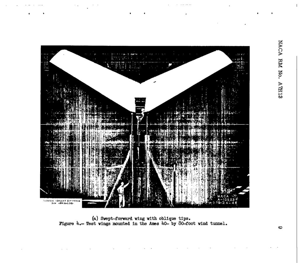
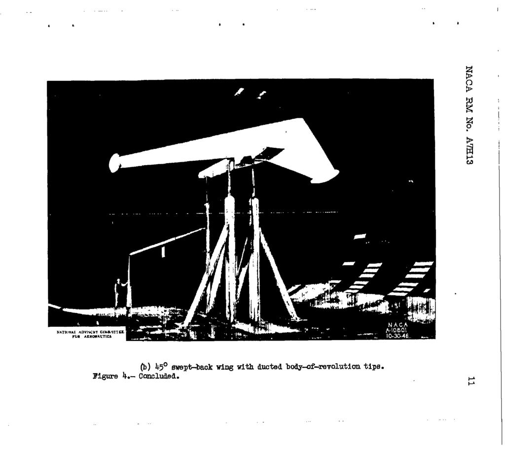
4 NACA RM No. Am13 3?he 45' mp&forva3d and the 45' eweptiback large-ecale wings were tested with four differently ahapd pairs of tips. The airfoil sections of the wings, normal to the quarte-hord line, &re WCA 0015 near the root and IWCA at the tip, as designated in figure8 1 an& 2. The specified sweep of each wing ie the sweep of its qusrte2c chord line. The tip8 are designated as parallel, oblique, nomal, and rounded, The nnmenclature of them first three shapes refers to the approximate -e of the edges relative to the air stream.) h each case the -8 with parallel t1p8 &re wings investiwbd and reported in reference 1. Geapaeiiric chesacterieticer of the wings wlth the wious tips &own in figures 1 an& 2. The 45' ewept-back wing ya8 ale0 tested with body4-revolutfan tips, wlth esd without ducts basic bodies have anrllca airfoil section and a lkeoot chord which is approximately twice the tip chord of the wing. mey were mounted with their center lines pamllel to and 3 inches above the chord plane of the we ducted bodies have 2 feet of the rea portion rammed to obtain sufficient duchrft &rea. Ihe duct inlet at the upper surpace junction of the ving and body is approximately 4 feet long, averwing 2$ fnche~ in height, and faire into a CincMiameter outlet, Figure 3 shows characteristics of the sweptback wing with body-of-revolution tips. The tests were- conducted in the Ames kcb by 809oot wind tunnel, The wings were attached to a boam and mounted in the tunnel 8.8 shown in figure 4. For most of the tests the win@o+ocen incidence WBB 5'. Emver, with the Bvept"forwe;rd Kizig at 5' incidence, angles. of attack beyond that for e lift could not be realized because of limitations imposed by the support eyatem. In order to determine the trend of poet-~tall characteristics, one test of the sweptforward wing with pardleg tips was made with the Ving-tcGboCan incidence increa~ed to 15, Tests were made varying the angle of attack from zero lift through stall for the Sxept-fmwaxd and mpt-back wings with each of the several tip ehapes installed. Each test was made twice, first for the purpose of obtaining force data and second vith the wing completely covered with tufts to obtain observations of the stdl progression.
5 4 NACA RM No. Am13 dynamic preeaure of 25 pounds per square foot, These correspond to Reynold8 nlzmbere baaed on the mean "IC chord of approximately 7.2 x 1W for the body-af-revolutlon tip teste, 9.3 x 1W for the other swepobeck wing teats, and 10.7 x 10s for the mpfforwapd. wing tests. The f mce data for the svegt-f orward wing are shown in f 1gu-m 5, and the records of the tdt obsematiune in figure 6. Similar data for the swept-back wing are shown in figures 8 Rnd 9, respectively. Force data for the swept-back wings with the bcdy of revolution tips 8;re shown in figure 10.!t%ere are a m differencee in the results presented for separate teste of apparently identical configurations, It ie reasoned that these differences a m the result of elight changes in configuration caused by reassemblies of the model between the various tester, Considering the objective8 of this investigation, these differencee do not appear to be of great signlficetnce. DISCUSSION It Is evident from the force test rebulte that no major chqe in maximum lift coefficient or pitching-mament characteristice were realized through the installation of any of the varioue-shaped tipa or the bodies of revolution. The maxlmum Improvement in C k waa To a large extent the VarieLtions in CI, occurring in the linear portion of the cme can be attrtbuted to differencee in. aepect ratio of the variaue configurations, rather than tip-shape change 0 The oblique tlpe effected so~me change^ in pitching moment at high anglee of attack for both the swept-f orward and the mpt-back wings, although the imgrovemente realized did not approach those that had been hoped for. For the evept-forward wing, pitching moment fe given in figure 7 lor a oente"grav1ty location of 0.15 M.A.C a reaflonable location with regard to bslance. Here it Is seen that the wetable pitching moment which sxleted near atall has been almost eliminated by the InakU.ation of the oblique tips. Thie change 18 accompanied by acme increase fn stability at lower anglee Of attack. the case Of the mept-back wing, the Oblique tips reduced the sfx&illty slightly in the low aagled-attack range in etdditlon to decreasing the unstable pitch- mament above a = 20 (fig. 8). d
6 NACA RM No. Am13 5 The tuft observations shared that tip shape had saw control over the stall progession of the swepiiforvard wing, though this was not reflected, except by the abov-ntfoned pitchimment chaqps, in the force measurements. 5 normal tips and, to a lesser degree, the oblique tips evidenced tip atall not shown by the other tip &apes and, &B a result, might reduce laterd~ootrol * effectivenees at high lift coefficiente. On the swept-back King the mioue tipe had little effect 011 the stall pro@ession indicated by the tufts (fig. 9). In each case the sfall wag characterized by a strong leadtnmdge separation progressing inboard from the tipe which, it might be erpected, could be little affected by tip shape. In thie and other swep% back wins studies, force teste ehox this sudden leadfng-dge flow separation is accompauied by a strong positive pitching+nnent increment, It would eeem, then, that if thie separ&tion can be delayed by 6-0 meam, me of the moat undesirable chazacterietice of sweptaack wings will be overcame. L Tuft obaervatiane nmde with either the ducted or the unducted body"-revolution tfps indicated that while the bodies tended to draw off the boundary layer at lov a&le of attack, the bounderrlayer drain control yebe so weak it became inadequate, asd the no& stall pattern appeared at very low lift coeff iciente. The tufts indicated a flat existed through the ducted body prior to stall, but it was apparently BO slight as to have PO measurable effect in &lam the stall. At the first appemance of tip stall, the str- tip'vortex moved inboard, end there xae no longer any flow through the duct. Ames Aeronautical 'laboratory, National Advieory Camittee for Aeronautics, Moffett Field, Calif..
7 NACA RM No. Am13 ROUNDED TIPS PARALLEL MOMENT CENTER LOCATED AT MAC/4. OBLIQUE Tipa NORMAL TIPS llbtkybl bwl5uw CoYyIlTEe mn IuIoNAIrrl- FIGURE I. - GEOMETRI CHARACTERISTICS OF 45-OEGREE SWEPT-FORWARD WlNG WITH VARIOUS TIPS..
8 NACA RM NO. A7H13. 7 ROUNDED Tips i- OBLLQUE T r PS NORMAL Ti PS t FIGURE.2_- GEOMETRIC CHARACTERISTtCS OF 45-DEGREE SWEPT-BACK WING WITH VARIO~~S TIPS-
9 8 NACA RM No. Am13 BODY OF REVOLUTION AIRFOIL BECTION: NACA DUCTED FIGURE 3.- BACK WING WITH BODY-OF-REVOLUTION TI P6. GEOMETRIC CHARACTERISTI'CS~~OF 45-DEGREE SWEPT-
10 I I
11
12 .....
13 .
14 NACA RM No. Am13 13 FIGURE 5.- AERODYNAMIC SWEPT -FORWARD CHARACTERtSTlCS OF 45 DEGREE WING Wt I H VARIOUS TIPS.
15 14 NACA RM No. Am13.
16 NACA RNI No. Am a NATtONAL ISVlSORY COMMITTEE FOR AERONAUUTICS.o "08 "12 PITCHING-MOMENT COEFFICIENT, m.15 FIGURE 7"COMPARISON OF PITCHING- MOMENT COEFFICIENT ABOUT.I5 MAG. FOR SWEPT-FORWARD WING WITH PARALLEL AND OBLIQUE TIPS.
17 16 NACA RM No. Am13 I? J 4 FtGURE 8.- AEROOYNAMIC CHARACTL;R\STICS OF 45-DEGREE SWEPT-BACK WING WITH VARTOVS TIPS.
18
19 18 NACA RM No. Am13 FIGURE 10.- AERODYNAMIC CHARACTERISTICS OF 45-DECREE SWEPT-BACK WING WITH BODY OF REVOLUTION TIPS.
20 #
FUSELAGE-MOUNTED FINS ON THE STATIC DIRECTIONAL STABILITY. By M. Leroy Spearman, Ross B. Robinson, and Cornelius Driver
 RESEARCH MEMORANDUM THE EFFECTS OF THE ADDITION OF SMALL FUSELAGE-MOUNTED FINS ON THE STATIC DIRECTIONAL STABILITY CHARACTERISTICS OF A MODEL OF A 45' SWEPT-WING AIRPLANE AT ANGLES OF ATTACK UP TO 15.3?
THE COLLEGE OF AERONAUTICS CRANFIELD
 THE COLLEGE OF AERONAUTICS CRANFIELD AERODYNAMIC CHARACTERISTICS OF A 40 SWEPT BACK WING OF ASPECT RATIO 4.5 by P. S. BARNA NOTE NO. 65 MAY, 1957 CRANFIELD A preliminary report on the aerodynamic characteristics
J. Szantyr Lecture No. 21 Aerodynamics of the lifting foils Lifting foils are important parts of many products of contemporary technology.
 J. Szantyr Lecture No. 21 Aerodynamics of the lifting foils Lifting foils are important parts of many products of contemporary technology. < Helicopters Aircraft Gliders Sails > < Keels and rudders Hydrofoils
RESEARCH MEMORANDUM FOR AERONAUTICS HAVING A TRZANGULAR WING OF ASPECT WETI0 3. Moffett Field, Calif. WASHINGTON. Ames Aeronautical Laboratory
 RESEARCH MEMORANDUM THE EFFECTS OF TRAILINGEDGE FLAPS ON THE SUBSONIC AERODYNAMIC CHARACTERISTICS OF AN AIRPLANE MODEL HAVING A TRZANGULAR WING OF ASPECT WETI0 3 By Bruce E. Tinling and A. V. I I Ames
AF101 to AF109. Subsonic Wind Tunnel Models AERODYNAMICS. A selection of optional models for use with TecQuipment s Subsonic Wind Tunnel (AF100)
") Page 1 of 4 A selection of optional models for use with TecQuipment s Subsonic Wind Tunnel (AF100) Dimpled Sphere Drag Model (from AF109) shown inside the TecQuipment AF100 Wind Tunnel. Cylinder, aerofoils,
Page 1 of 4 A selection of optional models for use with TecQuipment s Subsonic Wind Tunnel (AF100) Dimpled Sphere Drag Model (from AF109) shown inside the TecQuipment AF100 Wind Tunnel. Cylinder, aerofoils,
RESEARCH MEMORANDUM. WASHINGTON December 3, AERODYNl$MIC CHARACTERISTICS OF A MODEL? OF AN ESCAPE ...,
 .". -.%. ;& RESEARCH MEMORANDUM AERODYNl$MIC CHARACTERISTICS OF A MODEL? OF AN ESCAPE 1 \ < :. By John G. Presnell, Jr. w'..., '.., 3... This material contains information affecting the National Bfense
ROAD MAP... D-1: Aerodynamics of 3-D Wings D-2: Boundary Layer and Viscous Effects D-3: XFLR (Aerodynamics Analysis Tool)
") Unit D-1: Aerodynamics of 3-D Wings Page 1 of 5 AE301 Aerodynamics I UNIT D: Applied Aerodynamics ROAD MAP... D-1: Aerodynamics of 3-D Wings D-: Boundary Layer and Viscous Effects D-3: XFLR (Aerodynamics
Unit D-1: Aerodynamics of 3-D Wings Page 1 of 5 AE301 Aerodynamics I UNIT D: Applied Aerodynamics ROAD MAP... D-1: Aerodynamics of 3-D Wings D-: Boundary Layer and Viscous Effects D-3: XFLR (Aerodynamics
Low Speed Wind Tunnel Wing Performance
 Low Speed Wind Tunnel Wing Performance ARO 101L Introduction to Aeronautics Section 01 Group 13 20 November 2015 Aerospace Engineering Department California Polytechnic University, Pomona Team Leader:
External Tank- Drag Reduction Methods and Flow Analysis
 External Tank- Drag Reduction Methods and Flow Analysis Shaik Mohammed Anis M.Tech Student, MLR Institute of Technology, Hyderabad, India. G. Parthasarathy Associate Professor, MLR Institute of Technology,
Subsonic wind tunnel models
 aerodynamics AF1300a to AF1300l A selection of optional models for use with TecQuipment s Subsonic Wind Tunnel (AF1300) Dimpled Sphere Drag Model (from AF1300j) shown inside the TecQuipment AF1300 Wind
Aircraft Design: A Systems Engineering Approach, M. Sadraey, Wiley, Figures
 Aircraft Design: A Systems Engineering Approach, M. Sadraey, Wiley, 2012 Chapter 5 Wing Design Figures 1 Identify and prioritize wing design requirements (Performance, stability, producibility, operational
Investigation on 3-D Wing of commercial Aeroplane with Aerofoil NACA 2415 Using CFD Fluent
 Investigation on 3-D of commercial Aeroplane with Aerofoil NACA 2415 Using CFD Fluent Rohit Jain 1, Mr. Sandeep Jain 2, Mr. Lokesh Bajpai 3 1PG Student, 2 Associate Professor, 3 Professor & Head 1 2 3
INTERFERENCE EFFECT AND FLOW PATTERN OF FOUR BIPLANE CONFIGURATIONS USING NACA 0024 PROFILE
 Proceedings of the International Conference on Mechanical Engineering 211 (ICME211) 18-2 December 211, Dhaka, Bangladesh ICME11-FL-1 INTERFERENCE EFFECT AND FLOW PATTERN OF FOUR BIPLANE CONFIGURATIONS
Reduction of Skin Friction Drag in Wings by Employing Riblets
 Reduction of Skin Friction Drag in Wings by Employing Riblets Kousik Kumaar. R 1 Assistant Professor Department of Aeronautical Engineering Nehru Institute of Engineering and Technology Coimbatore, India
It should be noted that the symmetrical airfoil at zero lift has no pitching moment about the aerodynamic center because the upper and
 NAVWEPS -81-8 and high power, the dynamic pressure in the shaded area can be much greater than the free stream and this causes considerably greater lift than at zero thrust. At high power conditions the
AERODYNAMIC CHARACTERISTICS OF NACA 0012 AIRFOIL SECTION AT DIFFERENT ANGLES OF ATTACK
 AERODYNAMIC CHARACTERISTICS OF NACA 0012 AIRFOIL SECTION AT DIFFERENT ANGLES OF ATTACK SUPREETH NARASIMHAMURTHY GRADUATE STUDENT 1327291 Table of Contents 1) Introduction...1 2) Methodology.3 3) Results...5
SEMI-SPAN TESTING IN WIND TUNNELS
 25 TH INTERNATIONAL CONGRESS OF THE AERONAUTICAL SCIENCES SEMI-SPAN TESTING IN WIND TUNNELS S. Eder, K. Hufnagel, C. Tropea Chair of Fluid Mechanics and Aerodynamics, Darmstadt University of Technology
The effect of back spin on a table tennis ball moving in a viscous fluid.
 How can planes fly? The phenomenon of lift can be produced in an ideal (non-viscous) fluid by the addition of a free vortex (circulation) around a cylinder in a rectilinear flow stream. This is known as
CFD Study of Solid Wind Tunnel Wall Effects on Wing Characteristics
 Indian Journal of Science and Technology, Vol 9(45), DOI :10.17485/ijst/2016/v9i45/104585, December 2016 ISSN (Print) : 0974-6846 ISSN (Online) : 0974-5645 CFD Study of Solid Wind Tunnel Wall Effects on
AF100. Subsonic Wind Tunnel AERODYNAMICS. Open-circuit subsonic wind tunnel for a wide range of investigations into aerodynamics
 Open-circuit subsonic wind tunnel for a wide range of investigations into aerodynamics Page 1 of 4 Works with Computer, chair and work table shown for photographic purposes only (not included) Screenshot
Aerodynamic Terms. Angle of attack is the angle between the relative wind and the wing chord line. [Figure 2-2] Leading edge. Upper camber.
![Aerodynamic Terms. Angle of attack is the angle between the relative wind and the wing chord line. [Figure 2-2] Leading edge. Upper camber.](/thumbs/82/86661300.jpg "Aerodynamic Terms. Angle of attack is the angle between the relative wind and the wing chord line. [Figure 2-2] Leading edge. Upper camber.") Chapters 2 and 3 of the Pilot s Handbook of Aeronautical Knowledge (FAA-H-8083-25) apply to powered parachutes and are a prerequisite to reading this book. This chapter will focus on the aerodynamic fundamentals
Chapters 2 and 3 of the Pilot s Handbook of Aeronautical Knowledge (FAA-H-8083-25) apply to powered parachutes and are a prerequisite to reading this book. This chapter will focus on the aerodynamic fundamentals
HEFAT th International Conference on Heat Transfer, Fluid Mechanics and Thermodynamics July 2012 Malta
 HEFAT212 9 th International Conference on Heat Transfer, Fluid Mechanics and Thermodynamics 16 18 July 212 Malta AN EXPERIMENTAL STUDY OF SWEEP ANGLE EFFECTS ON THE TRANSITION POINT ON A 2D WING BY USING
STUDIES ON THE OPTIMUM PERFORMANCE OF TAPERED VORTEX FLAPS
 ICAS 2000 CONGRESS STUDIES ON THE OPTIMUM PERFORMANCE OF TAPERED VORTEX FLAPS Kenichi RINOIE Department of Aeronautics and Astronautics, University of Tokyo, Tokyo, 113-8656, JAPAN Keywords: vortex flap,
LEADING-EDGE VORTEX FLAPS FOR SUPERSONIC TRANSPORT CONFIGURATION -EFFECTS OF FLAP CONFIGURATIONS AND ROUNDED LEADING-EDGES-
 ICAS 2002 CONGRESS LEADING-EDGE VORTEX FLAPS FOR SUPERSONIC TRANSPORT CONFIGURATION -EFFECTS OF FLAP CONFIGURATIONS AND ROUNDED LEADING-EDGES- Kenichi RINOIE*, Dong Youn KWAK**, Katsuhiro MIYATA* and Masayoshi
Measurement of Pressure. The aerofoil shape used in wing is to. Distribution and Lift for an Aerofoil. generate lift due to the difference
 Measurement of Pressure Distribution and Lift for an Aerofoil. Objective The objective of this experiment is to investigate the pressure distribution around the surface of aerofoil NACA 4415 and to determine
A COMPUTATIONAL STUDY ON THE DESIGN OF AIRFOILS FOR A FIXED WING MAV AND THE AERODYNAMIC CHARACTERISTIC OF THE VEHICLE
 28 TH INTERNATIONAL CONGRESS OF THE AERONAUTICAL SCIENCES A COMPUTATIONAL STUDY ON THE DESIGN OF AIRFOILS FOR A FIXED WING MAV AND THE AERODYNAMIC CHARACTERISTIC OF THE VEHICLE Jung-Hyun Kim*, Kyu-Hong
EXPERIMENTAL INVESTIGATION OF LIFT & DRAG PERFORMANCE OF NACA0012 WIND TURBINE AEROFOIL
 EXPERIMENTAL INVESTIGATION OF LIFT & DRAG PERFORMANCE OF NACA0012 WIND TURBINE AEROFOIL Mr. Sandesh K. Rasal 1, Mr. Rohan R. Katwate 2 1 PG Student, 2 Assistant Professor, DYPSOEA Ambi Talegaon, Heat Power
PRESSURE DISTRIBUTION OF SMALL WIND TURBINE BLADE WITH WINGLETS ON ROTATING CONDITION USING WIND TUNNEL
 International Journal of Mechanical and Production Engineering Research and Development (IJMPERD ) ISSN 2249-6890 Vol.2, Issue 2 June 2012 1-10 TJPRC Pvt. Ltd., PRESSURE DISTRIBUTION OF SMALL WIND TURBINE
Pressure distribution of rotating small wind turbine blades with winglet using wind tunnel
 Journal of Scientific SARAVANAN & Industrial et al: Research PRESSURE DISTRIBUTION OF SMALL WIND TURBINE BLADES WITH WINGLET Vol. 71, June 01, pp. 45-49 45 Pressure distribution of rotating small wind
ScienceDirect. Investigation of the aerodynamic characteristics of an aerofoil shaped fuselage UAV model
 Available online at www.sciencedirect.com ScienceDirect Procedia Engineering 90 (2014 ) 225 231 10th International Conference on Mechanical Engineering, ICME 2013 Investigation of the aerodynamic characteristics
COMPUTATIONAL FLUID DYNAMIC ANALYSIS OF AIRFOIL NACA0015
 International Journal of Mechanical Engineering and Technology (IJMET) Volume 8, Issue 2, February 2017, pp. 210 219 Article ID: IJMET_08_02_026 Available online at http://www.iaeme.com/ijmet/issues.asp?jtype=ijmet&vtype=8&itype=2
Aerodynamic Analysis of a Symmetric Aerofoil
 214 IJEDR Volume 2, Issue 4 ISSN: 2321-9939 Aerodynamic Analysis of a Symmetric Aerofoil Narayan U Rathod Department of Mechanical Engineering, BMS college of Engineering, Bangalore, India Abstract - The
Chapter 5 Wing design - selection of wing parameters - 4 Lecture 22 Topics
 Chapter 5 Wing design - selection of wing parameters - Lecture Topics 5.3.9 Ailerons 5.3.0 Other aspects of wing design Example 5. 5.3.9 Ailerons The main purpose of the ailerons is to create rolling moment
C-1: Aerodynamics of Airfoils 1 C-2: Aerodynamics of Airfoils 2 C-3: Panel Methods C-4: Thin Airfoil Theory
 ROAD MAP... AE301 Aerodynamics I UNIT C: 2-D Airfoils C-1: Aerodynamics of Airfoils 1 C-2: Aerodynamics of Airfoils 2 C-3: Panel Methods C-4: Thin Airfoil Theory AE301 Aerodynamics I : List of Subjects
Chapter 5 Wing design - selection of wing parameters - 3 Lecture 21 Topics
 Chapter 5 Wing design - selection of wing parameters - 3 Lecture 21 Topics 5.3.2 Choice of sweep ( ) 5.3.3 Choice of taper ratio ( λ ) 5.3.4 Choice of twist ( ε ) 5.3.5 Wing incidence(i w ) 5.3.6 Choice
Computational Analysis of Cavity Effect over Aircraft Wing
 World Engineering & Applied Sciences Journal 8 (): 104-110, 017 ISSN 079-04 IDOSI Publications, 017 DOI: 10.589/idosi.weasj.017.104.110 Computational Analysis of Cavity Effect over Aircraft Wing 1 P. Booma
AERODYNAMICS I LECTURE 7 SELECTED TOPICS IN THE LOW-SPEED AERODYNAMICS
 LECTURE 7 SELECTED TOPICS IN THE LOW-SPEED AERODYNAMICS The sources of a graphical material used in this lecture are: [UA] D. McLean, Understanding Aerodynamics. Arguing from the Real Physics. Wiley, 2013.
ANALYSIS OF AERODYNAMIC CHARACTERISTICS OF A SUPERCRITICAL AIRFOIL FOR LOW SPEED AIRCRAFT
 ANALYSIS OF AERODYNAMIC CHARACTERISTICS OF A SUPERCRITICAL AIRFOIL FOR LOW SPEED AIRCRAFT P.Sethunathan 1, M.Niventhran 2, V.Siva 2, R.Sadhan Kumar 2 1 Asst.Professor, Department of Aeronautical Engineering,
DEC2B 194P a»»> v&* NATIONAL ADVISORY COMMITTEE FOR AERONAUTICS WARTIME REPORT ORIGINALLY ISSUED
 DEC2B 194P a»»> v&* NATIONAL ADVISORY COMMITTEE FOR AERONAUTICS WARTIME REPORT ORIGINALLY ISSUED /' October 19^5 as Restricted Bulletin Lf?I0f> "DSE OF VARIABLE-RATIO GEARED TABS TO IMPROVE STICK-FORCE
BUILD AND TEST A WIND TUNNEL
 LAUNCHING INTO AVIATION 9 2018 Aircraft Owners and Pilots Association. All Rights Reserved. UNIT 2 SECTION D LESSON 2 PRESENTATION BUILD AND TEST A WIND TUNNEL LEARNING OBJECTIVES By the end of this lesson,
Aerodynamic investigations on a wing in ground effect
 Aerodynamic investigations on a wing in ground effect A summary of NLR activities in the Seabus-Hydaer programme W.B. de Wolf Nationaal Lucht- en Ruimtevaartlaboratorium National Aerospace Laboratory NLR
Aerodynamics Principles
 Aerodynamics Principles Stage 1 Ground Lesson 3 Chapter 3 / Pages 2-18 3:00 Hrs Harold E. Calderon AGI, CFI, CFII, and MEI Lesson Objectives Become familiar with the four forces of flight, aerodynamic
Low-Speed Wind-Tunnel Investigation of the Stability and Control Characteristics of a Series of Flying Wings With Sweep Angles of 50
 NASA Technical Memorandum 464 Low-Speed Wind-Tunnel Investigation of the Stability and Control Characteristics of a Series of Flying Wings With Sweep Angles of 5 Scott P. Fears Lockheed Engineering & Sciences
Reynolds Number Effects on Leading Edge Vortices
 Reynolds Number Effects on Leading Edge Vortices Taken From AIAA-2002-2839 Paper Reynolds Numbers Considerations for Supersonic Flight Brenda M. Kulfan 32nd AIAA Fluid Dynamics Conference and Exhibit St.
Anna University Regional office Tirunelveli
 Effect of Tubercle Leading Edge Control Surface on the Performance of the Double Delta Wing Fighter Aircraft P Sharmila 1, S Rajakumar 2 1 P.G. Scholar, 2 Assistant Professor, Mechanical Department Anna
Incompressible Potential Flow. Panel Methods (3)
") Incompressible Potential Flow Panel Methods (3) Outline Some Potential Theory Derivation of the Integral Equation for the Potential Classic Panel Method Program PANEL Subsonic Airfoil Aerodynamics Issues
Incompressible Potential Flow Panel Methods (3) Outline Some Potential Theory Derivation of the Integral Equation for the Potential Classic Panel Method Program PANEL Subsonic Airfoil Aerodynamics Issues
AerE 343L: Aerodynamics Laboratory II. Lab Instructions
 AerE 343L: Aerodynamics Laboratory II Lab Instructions Lab #2: Airfoil Pressure Distribution Measurements and Calibration of a Small Wind Tunnel Instructor: Dr. Hui Hu Department of Aerospace Engineering
CASE FIL. c p y 6umm. TEC}BIC\.L :.f.icra:tfll:js. :TATICNL ADVISORY CO::TTEE FOP AERoN.:uTICs. No By 0. Schreik
 CASE FIL c p y 6umm TEC}BIC\.L :.f.icra:tfll:js :TATICNL ADVISORY CO::TTEE FOP AERoN.:uTICs No. 375 EFFECT OF Ro TJG:1:Ess Oi PRCPETIES OF IYOILS By 0. Schreik Froi "Vor1iufige LTittei1unen cer Aercdmarnischen
Effect of Leading- and Trailing-Edge Flaps on Clipped Delta Wings With and Without Wing Camber at Supersonic Speeds
 NASA Technical Memorandum 4542 Effect of Leading- and Trailing-Edge Flaps on Clipped Delta Wings With and Without Wing Camber at Supersonic Speeds Gloria Hernandez, Richard M. Wood, and Peter F. Covell
Influence of wing span on the aerodynamics of wings in ground effect
 Influence of wing span on the aerodynamics of wings in ground effect Sammy Diasinos 1, Tracie J Barber 2 and Graham Doig 2 Abstract A computational fluid dynamics study of the influence of wing span has
DIRECCION DE PERSONAL AERONAUTICO DPTO. DE INSTRUCCION PREGUNTAS Y OPCIONES POR TEMA
 MT DIREION DE PERSONL ERONUTIO DPTO. DE INSTRUION PREGUNTS Y OPIONES POR TEM 1 TEM: 0292 FLT/DSP - (HP. 03) ERODYNMIS OD_PREG: PREG20084823 (8324) PREGUNT: When are inboard ailerons normally used? Low-speed
Aerodynamic Simulation of Runback Ice Accretion
 1st AIAA Atmospheric and Space Environments Conference 22-25 June 2009, San Antonio, Texas AIAA 2009-4261 Aerodynamic Simulation of Runback Ice Accretion Andy P. Broeren NASA Glenn Research Center, Cleveland,
EXPERIMENTAL INVESTIGATION OF THE EFFECT OF VARIOUS WINGLET SHAPES ON THE TOTAL PRESSURE DISTRIBUTION BEHIND A WING
 24 TH INTERNATIONAL CONGRESS OF THE AERONAUTICAL SCIENCES EXPERIMENTAL INVESTIGATION OF THE EFFECT OF VARIOUS WINGLET SHAPES ON THE TOTAL PRESSURE DISTRIBUTION BEHIND A WING Mohammad Reza Soltani, Kaveh
EXPERIMENTAL ANALYSIS OF FLOW OVER SYMMETRICAL AEROFOIL Mayank Pawar 1, Zankhan Sonara 2 1,2
 EXPERIMENTAL ANALYSIS OF FLOW OVER SYMMETRICAL AEROFOIL Mayank Pawar 1, Zankhan Sonara 2 1,2 Assistant Professor,Chandubhai S. Patel Institute of Technology, CHARUSAT, Changa, Gujarat, India Abstract The
COMPUTER-AIDED DESIGN AND PERFORMANCE ANALYSIS OF HAWT BLADES
 5 th International Advanced Technologies Symposium (IATS 09), May 13-15, 2009, Karabuk, Turkey COMPUTER-AIDED DESIGN AND PERFORMANCE ANALYSIS OF HAWT BLADES Emrah KULUNK a, * and Nadir YILMAZ b a, * New
TAKEOFF & LANDING IN ICING CONDITIONS
 Original idea from Captain A. Wagner T TAKEOFF & LANDING IN ICING CONDITIONS here have been a number of accidents related to take-off in conditions in which snow and/or other forms of freezing precipitation
CFD ANALYSIS OF FLOW AROUND AEROFOIL FOR DIFFERENT ANGLE OF ATTACKS
 www.mechieprojects.com CFD ANALYSIS OF FLOW AROUND AEROFOIL FOR DIFFERENT ANGLE OF ATTACKS PRESENTATION OUTLINE AIM INTRODUCTION LITERATURE SURVEY CFD ANALYSIS OF AEROFOIL RESULTS CONCLUSIONS www.mechieprojects.com
Subsonic Wind Tunnel 300 mm
 aerodynamics AF1300 An open circuit suction subsonic wind tunnel with a working section of 300 mm by 300 mm and 600 mm long Screenshot of the optional VDAS software Saves time and money compared to full-scale
EFFECT OF GURNEY FLAPS AND WINGLETS ON THE PERFORMANCE OF THE HAWT
 Chapter-6 EFFECT OF GURNEY FLAPS AND WINGLETS ON THE PERFORMANCE OF THE HAWT 6.1 Introduction The gurney flap (wicker bill) was a small flat tab projecting from the trailing edge of a wing. Typically it
The Effect of Canard Configurations to the Aerodynamics of the Blended Wing Body
 Vol:7, No:5, 213 The Effect of Canard Configurations to the Aerodynamics of the Blended Wing Body Zurriati Mohd Ali, Wahyu Kuntjoro, and Wirachman Wisnoe International Science Index, Aerospace and Mechanical
Aerodynamic Analysis of Blended Winglet for Low Speed Aircraft
 , July 1-3, 2015, London, U.K. Aerodynamic Analysis of Blended Winglet for Low Speed Aircraft Pooja Pragati, Sudarsan Baskar Abstract This paper provides a practical design of a new concept of massive
DIRECCION DE PERSONAL AERONAUTICO DPTO. DE INSTRUCCION PREGUNTAS Y OPCIONES POR TEMA
 MT DIREION DE PERSONL ERONUTIO DPTO. DE INSTRUION PREGUNTS Y OPIONES POR TEM 1 TEM: 0114 TP - (HP. 03) ERODYNMIS OD_PREG: PREG20078023 (8358) PREGUNT: What is the safest and most efficient takeoff and
Study of a Swept Wing with Leading-Edge Ice Using a Wake Survey Technique
 51st AIAA Aerospace Sciences Meeting including the New Horizons Forum and Aerospace Exposition 7-1 January 213, Grapevine (Dallas/Ft. Worth Region), Texas AIAA 213-245 Study of a Swept Wing with Leading-Edge
The Influence of Battle Damage on the Aerodynamic Characteristics of a Model of an Aircraft
 Proceedings of the 26 WSEAS/IASME International Conference on Fluid Mechanics, Miami, Florida, USA, January 18-2, 26 (pp7-76) The Influence of Battle on the Aerodynamic Characteristics of a Model of an
Drag Divergence and Wave Shock. A Path to Supersonic Flight Barriers
 Drag Divergence and Wave Shock A Path to Supersonic Flight Barriers Mach Effects on Coefficient of Drag The Critical Mach Number is the velocity on the airfoil at which sonic flow is first acquired If
AE Dept., KFUPM. Dr. Abdullah M. Al-Garni. Fuel Economy. Emissions Maximum Speed Acceleration Directional Stability Stability.
 Aerodynamics: Introduction Aerodynamics deals with the motion of objects in air. These objects can be airplanes, missiles or road vehicles. The Table below summarizes the aspects of vehicle performance
PERFORMANCE OF A FLAPPED DUCT EXHAUSTING INTO A COMPRESSIBLE EXTERNAL FLOW
 24 TH INTERNATIONAL CONGRESS OF THE AERONAUTICAL SCIENCES PERFORMANCE OF A FLAPPED DUCT EXHAUSTING INTO A COMPRESSIBLE EXTERNAL FLOW P. R. Pratt, J. K. Watterson, E. Benard, S. Hall School of Aeronautical
AERODYNAMIC CHARACTERISTICS OF SPIN PHENOMENON FOR DELTA WING
 ICAS 2002 CONGRESS AERODYNAMIC CHARACTERISTICS OF SPIN PHENOMENON FOR DELTA WING Yoshiaki NAKAMURA (nakamura@nuae.nagoya-u.ac.jp) Takafumi YAMADA (yamada@nuae.nagoya-u.ac.jp) Department of Aerospace Engineering,
Experimental and Theoretical Investigation for the Improvement of the Aerodynamic Characteristic of NACA 0012 airfoil
 International Journal of Mining, Metallurgy & Mechanical Engineering (IJMMME) Volume 2, Issue 1 (214) ISSN 232 46 (Online) Experimental and Theoretical Investigation for the Improvement of the Aerodynamic
Lift for a Finite Wing. all real wings are finite in span (airfoils are considered as infinite in the span)
") Lift for a Finite Wing all real wings are finite in span (airfoils are considered as infinite in the span) The lift coefficient differs from that of an airfoil because there are strong vortices produced
Lift for a Finite Wing all real wings are finite in span (airfoils are considered as infinite in the span) The lift coefficient differs from that of an airfoil because there are strong vortices produced
Avai 193 Fall 2016 Laboratory Greensheet
 Avai 193 Fall 2016 Laboratory Greensheet Lab Report 1 Title: Instrumentation Test Technique Research Process: Break into groups of 4 people. These groups will be the same for all of the experiments performed
Incompressible Flow over Airfoils
 Road map for Chap. 4 Incompressible Flow over Airfoils Aerodynamics 2015 fall - 1 - < 4.1 Introduction > Incompressible Flow over Airfoils Incompressible flow over airfoils Prandtl (20C 초 ) Airfoil (2D)
NUMERICAL INVESTIGATION FOR THE ENHANCEMENT OF THE AERODYNAMIC CHARACTERISTICS OF AN AEROFOIL BY USING A GURNEY FLAP
 Geotec., Const. Mat. & Env., ISSN:2186-2990, Japan, DOI: http://dx.doi.org/10.21660/2017.34.2650 NUMERICAL INVESTIGATION FOR THE ENHANCEMENT OF THE AERODYNAMIC CHARACTERISTICS OF AN AEROFOIL BY USING A
Twist Distributions for Swept Wings, Part 3
 On the Wing... #163 Twist istributions for Swept Wings, Part 3 In Part 1 we defined and provided examples of lift distributions. Part 2 examined stalling patterns of various planforms and introduced the
Improved Aerodynamic Characteristics of Aerofoil Shaped Fuselage than that of the Conventional Cylindrical Shaped Fuselage
 International Journal of Scientific & Engineering Research Volume 4, Issue 1, January-213 1 Improved Aerodynamic Characteristics of Aerofoil Shaped Fuselage than that of the Conventional Cylindrical Shaped
No Description Direction Source 1. Thrust
 AERODYNAMICS FORCES 1. WORKING TOGETHER Actually Lift Force is not the only force working on the aircraft, during aircraft moving through the air. There are several aerodynamics forces working together
SOARING AND GLIDING FLIGHT OF THE BLACK VULTURE
 [ 280 ] SOARING AND GLIDING FLIGHT OF THE BLACK VULTURE BY B. G. NEWMAN* Department of Engineering, University of Cambridge {Received 10 September 1957) INTRODUCTION In 1950 Raspet published an interesting
Aerodynamics of Winglet: A Computational Fluid Dynamics Study Using Fluent
 Aerodynamics of : A Computational Fluid Dynamics Study Using Fluent Rohit Jain 1, Mr. Sandeep Jain, Mr. Lokesh Bajpai 1PG Student, Associate Professor, Professor & Head 1 Mechanical Engineering Department
Aerodynamic investigation of Winglets on Wind Turbine Blades using CFD
 Risø-R-1543(EN) Aerodynamic investigation of Winglets on Wind Turbine Blades using CFD Jeppe Johansen and Niels N. Sørensen Risø National Laboratory Roskilde Denmark February 26 Author: Jeppe Johansen
The Effect of Slot Configuration on Active Flow Control Performance of Swept Wings at. Low Reynolds Numbers. Thesis
 The Effect of Slot Configuration on Active Flow Control Performance of Swept Wings at Low Reynolds Numbers Thesis Presented in Partial Fulfillment of the Requirements for Graduation with Honors Research
RESEARCH MEMORANDUM NATIONAL ADVISORY COMMITTEE FOR AERONAUTICS .'. L. ' By Gerald V. Foster " WASHINGTON March 6, 1958
 RESEARCH MEMORANDUM INVESTIGATION OF THE LONGITUDINAL AERODYNAMIC CHARACTERISTICS OF A TRAPEZOIDAL-WING AIRPLANE MODEL WITH VAF?IOUS VERTICAL POSITIONS OF WING AND HORIZONTAL TAIL AT MACH NUMBERS OF 1.41
Flow Field Investigation of Flat Bottom Aerofoil under Ground Effect
 IOSR Journal of Mechanical and Civil Engineering (IOSR-JMCE) e-issn: 2278-1684,p-ISSN: 2320-334X, Volume 12, Issue 4 Ver. VI (Jul. - Aug. 2015), PP 83-88 www.iosrjournals.org Flow Field Investigation of
Aerofoil Profile Analysis and Design Optimisation
 Journal of Aerospace Engineering and Technology Volume 3, Issue 2, ISSN: 2231-038X Aerofoil Profile Analysis and Design Optimisation Kondapalli Siva Prasad*, Vommi Krishna, B.B. Ashok Kumar Department
University of Bristol - Explore Bristol Research. Publisher's PDF, also known as Version of record
 Liu, X., Azarpeyvand, M., & Joseph, P. (2015). On the acoustic and aerodynamic performance of serrated airfoils. Paper presented at The 22nd International Congress on Sound and Vibration, Florence, France.
The subsonic compressibility effect is added by replacing. with
 Swept Wings The main function of a swept wing is to reduce wave drag at transonic and supersonic speeds. Consider a straight wing and a swept wing in a flow with a free-stream velocity V. Assume that the
THE CONCEPT OF HIGH-LIFT, MILD STALL WING
 24 TH INTERNATIONAL CONGRESS OF THE AERONAUTICAL SCIENCES THE CONCEPT OF HIGH-LIFT, MILD STALL WING Alexander Nagel and Misha Shepshelovich Engineering Center, Israel Aircraft Industries Keywords: airfoils,
Aerodynamic Analyses of Horizontal Axis Wind Turbine By Different Blade Airfoil Using Computer Program
 ISSN : 2250-3021 Aerodynamic Analyses of Horizontal Axis Wind Turbine By Different Blade Airfoil Using Computer Program ARVIND SINGH RATHORE 1, SIRAJ AHMED 2 1 (Department of Mechanical Engineering Maulana
14th Applied Aerodynamics Conference June 17-20, 1996 / New Orleans, LA
 AIAA 96-2386 Study of Semi-Span Model Testing Techniques G. M. Gatlin and R. J. McGhee NASA Langley Research Center Hampton, VA 23681-1 14th Applied Aerodynamics Conference June 17-2, 1996 / New Orleans,
Design and Development of Micro Aerial Vehicle
 Advances in Aerospace Science and Applications. ISSN 2277-3223 Volume 4, Number 1 (2014), pp. 91-98 Research India Publications http://www.ripublication.com/aasa.htm Design and Development of Micro Aerial
CFD AND EXPERIMENTAL STUDY OF AERODYNAMIC DEGRADATION OF ICED AIRFOILS
 Colloquium FLUID DYNAMICS 2008 Institute of Thermomechanics AS CR, v.v.i., Prague, October 22-24, 2008 p.1 CFD AND EXPERIMENTAL STUDY OF AERODYNAMIC DEGRADATION OF ICED AIRFOILS Vladimír Horák 1, Dalibor
NUMERICAL INVESTIGATION OF AERODYNAMIC CHARACTERISTICS OF NACA AIRFOIL WITH A GURNEY FLAP
 Int. J. Mech. Eng. & Rob. Res. 2012 MasoudJahanmorad Nouri et al., 2012 Research Paper ISSN 2278 0149 www.ijmerr.com Vol. 1, No. 3, October 2012 2012 IJMERR. All Rights Reserved NUMERICAL INVESTIGATION
2-D Computational Analysis of a Vertical Axis Wind Turbine Airfoil
 2-D Computational Analysis of a Vertical Axis Wind Turbine Airfoil Akshay Basavaraj1 Student, Department of Aerospace Engineering, Amrita School of Engineering, Coimbatore 641 112, India1 Abstract: This
NATIONAL '-ADVISORY COMMITTEE FOR AERONAUTICS I I...,,. :-, [a (: I' <V>* d J WASHINGTON. Bureau of Aeronautics, Department of the Navy.
 ~,,. for the Bureau of Aeronautics, Department of the Navy WIND-TUNNEL IMTESTIGATION AT LOW SPEED OF THE ROLLING STABILITY DERIVATIVES OF A l/lo-scale MODEL OF THE DOUGLAS A4D-1 AntPLANE TED NO. NACA DE
IMPACT OF FUSELAGE CROSS SECTION ON THE STABILITY OF A GENERIC FIGHTER
 IMPACT OF FUSELAGE CROSS SECTION ON THE STABILITY OF A GENERIC FIGHTER Robert M. Hall NASA Langley Research Center Hampton, Virginia ABSTRACT Many traditional data bases, which involved smooth-sided forebodies,
High Swept-back Delta Wing Flow
 Advanced Materials Research Submitted: 2014-06-25 ISSN: 1662-8985, Vol. 1016, pp 377-382 Accepted: 2014-06-25 doi:10.4028/www.scientific.net/amr.1016.377 Online: 2014-08-28 2014 Trans Tech Publications,
Numerical Investigation of Multi Airfoil Effect on Performance Increase of Wind Turbine
 International Journal of Engineering & Applied Sciences (IJEAS) International Journal of Engineering Applied Sciences (IJEAS) Vol.9, Issue 3 (2017) 75-86 Vol.x, Issue x(201x)x-xx http://dx.doi.org/10.24107/ijeas.332075
Fighter aircraft design. Aerospace Design Project G. Dimitriadis
 Fighter aircraft design Aerospace Design Project 2017-2018 G. Dimitriadis General configuration The elements of the general configuration are the following: Wing Wing placement Airfoil Number of engines
Effect of High-Lift Devices on Aircraft Wing
 IOSR Journal of Engineering (IOSRJEN) ISSN (e): 2250-3021, ISSN (p): 2278-8719 PP 01-05 www.iosrjen.org Effect of High-Lift Devices on Aircraft Wing Gaurav B. Mungekar 1, Swapnil N. More 1, Samadhan V.
Comparing GU & Savier airfoil equipped half canard In S4 wind tunnel (France)
") Some notes about Comparing GU & Savier airfoil equipped half canard In S4 wind tunnel (France) Matthieu Scherrer Adapted from Charlie Pujo & Nicolas Gorius work Contents Test conditions 3. S-4 Wind-tunnel.............................................
Some notes about Comparing GU & Savier airfoil equipped half canard In S4 wind tunnel (France) Matthieu Scherrer Adapted from Charlie Pujo & Nicolas Gorius work Contents Test conditions 3. S-4 Wind-tunnel.............................................
Wind loads investigations of HAWT with wind tunnel tests and site measurements
 loads investigations of HAWT with wind tunnel tests and site measurements Shigeto HIRAI, Senior Researcher, Nagasaki R&D Center, Technical Headquarters, MITSUBISHI HEAVY INDSUTRIES, LTD, Fukahori, Nagasaki,