SLR Missile Thunderboat
|
|
|
- Alexandrina Fitzgerald
- 6 years ago
- Views:
Transcription

1 J M P H O B B Y G R O U P L L C SLR Missile Thunderboat Zippkits R/C Boats BUILDING INSTRUCTIONS 2017 JMP Hobby Group LLC Indiana USA 1
2 Introduction Thank you for purchasing this kit. We are sure that it will provide you with many hours of enjoyment. Please take the time to read this entire manual before building this boat. You will become familiar with the building order, and less likely to make mistakes. This kit is not a toy. Although R/C boating is a fun and rewarding hobby, it can be dangerous if not done with common sense and safety in mind. Just about anyone should be able to build this kit, but it should not be operated by children without close adult supervision. Here are a few safety tips: Never operate your boat alone. If you get hurt, you may not be able to drive for help. Never, ever operate your boat in an area where there are full size boats or swimmers. If something happens, a 15 pound object traveling at 60+ mph can do serious damage. Always use a failsafe. This shuts the engine off in the event of radio signal loss. Test the failsafe each day of running, by shutting off your transmitter. Always carry a fire extinguisher, as gasoline is extremely flammable. The manufacturer assumes no liability for damages or other loss in the use of this product, as we have no control over the construction or end use of this product. Purpose The SLR Missile Thunderboat is a new and improved boat, based on our popular Bullitt Thunderboat. 2
3 This record holding design was developed by Scott Liddycoat, full size boat racer (holder of several US 1 championships) and monster truck driver. Hence the SLR designation for Scott Liddycoat Racing. Thunderboats are scale type hydros specifically designed for gasoline power. The Missile was designed as an easy to build kit that is also easy to setup, and very predictable to drive. It has excellent stability and turning ability, and handles rough water very well. The secret to its outstanding performance is the modern design features, such as the sponson angle of attack, non-trip and deck crown. All these elements add up to an aerodynamically sound design. The SLR Missile adds several new design elements that make the boat more efficient (faster) and easier to build. The SLR Missile is also legal in all Thunderboat classes in both IMPBA and NAMBA. You can build this boat without having the engine or radio, but it does make it easier to have them available when you build. You can use any gasoline engine, as long as it has mounts for 5 inch rails. Please note that this boat was designed for the Zenoah style marine engines. Other engines may not fit without cutting, and may not fit under the cowling. The SLR Missile was designed and optimized through 4 different hulls. This allows us to make small changes, and provides you with the very best we have to offer for performance and ease of assembly. Because of this, the pictures may differ slightly from your parts, or a picture may seem out of sequence. This is normal, and is due mostly to running changes in the design. 3
4 Preparation Tools and supplies needed to build: Small wood plane (mini plane) Sanding blocks with 80 and 220 grit paper Drill with bits Square FLAT Workbench Titebond III wood glue Good quality 30 minute epoxy Epoxy finishing resin, West Systems epoxy, MAS epoxy, etc. Lots of clamps! Spring clamps, paper clamps, c clamps, etc. Razor saw Masking tape Wood filler Primer Paint 4
5 Additional items needed to complete: Gasoline engine (Zenoah 260PUM with 257 carburetor recommended)..250 Collet for engine (Zipp 3440) inch cable w/welded stub shaft (Zipp 3445) Tuned pipe w/drop header (Zipp 2011 and 2018) 2 channel surface radio with 1 standard and 1 heavy duty servo (150 in/oz minimum) Throttle pushrod (2-56 or 4-40 Size) with Clevises (Zipp 3462 and 3459) x12 Pushrods (Zipp 3463) ¼ -5/16 OD carbon pushrod 2 pushrod seals (Zipp 3404 or 3422) ounce Fuel Cell (Zipp 3504 or 3506).250 strut (Zipp 3416).250 drive dog (Zipp 3442 or 3448) 7016/3 or 6717/3 prop (Zipp 4003) Prop nuts (Zipp 3450) Engine Mounts (Zipp 3409 for Zenoah) Cable grease (Zipp 3532) Large rudder (water pickup type) (Zipp 3413) 8 feet large silicone tubing (water line) (Zipp 3461) 12 inch length of 11/32 brass tubing (Zipp 3453) 36 inch length of 5/16 brass tubing (Zipp 3452) Optional Floatation (pool noodles, foam, etc.) 5
6 Before we can start building, we need to do some prep work. Good prep work will pay off later with a straight, true running boat. First, we need a flat work surface. Nothing else will do. The entire boat will be built on this, so make sure it is right. We are ready to start the build! Let s identify the parts in the sheets. Don t remove the parts until you actually need them, as some look similar, but are not the same. This boat is not symmetrical. The right and left are not the same, so it is critical that you note the parts correctly, or they will not fit. Note that all reference to right or left are as if you were sitting in the boat. All parts are marked with either a laser etch or two holes. Two holes ALWAYS indicate right side. A note about glue: We use and recommend Titebond III wood glue for most of the construction. This is available at Home Depot or Lowes. For any raw wood to wood joint, we prefer Titebond III. For any joint that is not wood, or wood that has been sealed, we recommend 30 minute epoxy. The decks should always be glued with 30 minute epoxy, as they will already have been sealed with two coats of epoxy. You can also build the entire boat with 30 minute epoxy if you wish. 6


7 We like the Great Planes 11 inch bar sanders Use good quality epoxy and finishing resin Epoxy brush trimmed for fast epoxy application Your life will be much easier with one of these Get lots of these 7


8 Let s get started Bottom ready for assembly. Test fit first. Bottom halves and extensions epoxied. Bottom The first thing to be done is to join the bottom halves. Use 30 minute epoxy for this. Sand off the tiny bumps where the edges meet. Test fit the bottoms, as well as the front extensions. Tape the two bottom sheets tightly together on one side. On the other side, use a continuous strip of tape on the seam. This will be a tape hinge. Carefully remove the tape you put on the other side. Mix up some 30 minute epoxy and coat both edges while you open up the tape hinge. Make sure both edges are coated well. Close the hinge, wipe off excess glue and glue the front extensions in place. Work quickly. Tightly tape everything and set aside overnight. Note tape. If you are concerned about the sides not meeting correctly, put waxed paper under and over the bottom, and stack weights along all seams to keep it flat. Engine rails before laminating (above), and after. Laminates Laminate the 4 engine rails into two ¼ inch rails. All engine rail parts are identical. 8


9 Bulkhead 3 has 3 laminations: 3, 3A and FD. Bulkheads 3, 3A and FD. Lay bulkheads 3 and 3A with the two holes on your left. Using Titebond III, glue 3A on top of 3. Be sure that both bulkheads line up all the way around. Use scrap 1/8 wood to be sure that the slots are lined up correctly. Clamp until cured. Glue the turn fin doubler (FD) to 3A with Titebond III. Use a scrap of 1/8 ply to be sure that the slot is lined up. BH3 and 3A laminated. FD ready. Clamp until cured. Install the two blind nuts to the turn fin doubler with 30 minute epoxy. Laminate the parts of the pipe mount (PM). FD Doubler installation. 9


10 Jig clamped to board. Pipe mount parts laminated. Frame assembly Remove all of the interior parts of the building jig and clamp, screw or nail it to your flat work surface. If you are married, we do not recommend the kitchen table for this Our building board is two pieces of ¾ MDF. Make sure that the two holes in the rear of the jig are on your left side. This is the hull s right side, and you will put all bulkheads in place with the two holes on the same side. Glue the bulkheads into the slots in the jig. Be sure that the bulkheads are 90 degrees to the jig, and are fully seated in the jig slots. Use a square. Engine rails in place. Note tape. Bulkhead 3 assembly should go in place so that the blind nuts are facing forward. 10


11 Glue in the engine rails with Titebond or epoxy. Glue to bulkheads 1, 2 and 3. Run a strip of tape between bulkheads 1 and 3. Just tight enough to keep the bulkheads tight against the engine rails. BH2 must be straight up so that the bottom will fit. Use a square to be sure that bulkhead 2 remains straight up. Bulkhead 2 straight across and square. Use a straight edge across bulkhead 2 to make sure it is straight. If not, the bottom won t fit. Allow to cure. Note that air vents are on the left side. Test fit and glue both side stringers. 11
. These cooling slots help cool the tuned pipe, and should be retained.")
.")
 to the back of bulkhead 5.")

12 Be sure that the stringer with cooling slots goes on the side opposite the two holes (opposite side from the turn fin). These cooling slots help cool the tuned pipe, and should be retained. Side stringer being glued in place. Note clamps. Clamp at bulkheads 4 and 5, and tape the rear corners tightly. Before the glue dries, check to be sure that the stringers are lined up with each forward bulkhead (1, 2 and 3). See picture. This is mainly cosmetic, but it will make it easier to install the sponson decks later. Side stringers flush with bulkhead edge. When cured, glue the transom (T) to the back of bulkhead 5. Center it so that it if flush at the top and bottom, as well as both sides. The bevels will not line up. Clamp well and allow to cure. We like to clamp a piece of straight wood or metal to the transom while laminating it to bulkhead 5. Wood clamped to transom to keep it straight. 12


.")
13 Glue in the transom brace at this time. This is glued into the front of bulkhead 5, and will fit into the bottom later. Brace can go in either way. Transom brace glued in place. Transom not yet laminated in this photo. Inner Chines Glue in both inner chines (IC and RIC). Be sure that they are flush, or nearly so, with the bulkheads. Inner chines in place. 13


14 Bottom Sand the bulkheads, rails and stringers so that there are no bumps or other irregularities that would prevent the bottom from sitting flat. Test fit the bottom assembly onto the frame. Tip: Leave strips of masking tape in place on the outside of the bottom. The tape will help prevent the bottom seam from splitting before you apply the fiberglass cloth later. Be sure that the bottom fits well, and all slots line up. Plan your clamping and weights now. Lots of weight, tape and clamps on the bottom. When you are happy with the fit, use Titebond or epoxy to glue the bottom in place. Work quickly. Clamp and weight as much as you can. We use several batteries along with some 5 pound weights. Don t forget to snap in the transom brace. Double check that all tabs are in slots, and everything looks good. When in doubt, add more weight. Quickly check and adjust the angle of bulkhead 3. It must be 100% square to the sides. Loosen the clamp and adjust until 90 degrees. Double check this. Checking that BH3 is perfectly square. This is critical on the turn fin side, as it will cause the boat to run funny if not right. Do the other side as well. Work quickly before the glue dries. 14


 at the same time.")
15 Outer Chines After the bottom has cured, glue in both outer chines (OC and ROC). These fit into the slots, and just glue to the bottom at the tip. Outer chine in place. Sponson Chines and Spray Rails Sand a slight bevel on the tips of the sponson chines (SC and RSC) so that they fit against BH1 nicely. Sponson chine in place. Glue spray rail at the same time. Bevel the front of the sponson chines here. When satisfied with the fit, glue in place. Glue in the spray rails (not marked, and R) at the same time. Clamp as needed, and be sure that the spray rails are sitting on the bulkheads. Spray rail glued in place. Clamp to SC. Allow to cure 15


16 Rear Non-Trip Check the fit of the rear non-trip pieces. You will probably need to bevel them very slightly near bulkhead 4. Use your sanding block with 80 grit to break the edge of the non-trip near BH4. Rear non-trips in place. Right and left are the same. There will be a gap at the front, and a small notch at the rear that will require filling. When happy with the fit, glue in place. Tape tightly and allow to cure. Rear non-trip taped tightly in place. Forward Non Trip Using your razor plane and 80 grit sanding block, sand the spray rail and outer chine so that the non-trip sheeting will lie flat. Go all the way onto the bottom sheet, as far as the outer chine goes. Sanding for sponson non-trip. 16


17 When you are satisfied that the sheeting will lay flat on the sponsons, glue in place. Sponson non-trip area sanded and ready. Clamp until you are 100% positive that the sheeting is in full contact everywhere. Make sure that the sheeting is at least flush at the top and bottom. Non-trip sheeting in place. Lots of clamps. Allow to cure. 17


18 We should go into the clamp business! Sponson Bottoms Front of sponson bottom beveled for nice transition. Bevel the front of the forward sponson bottoms (not marked, and R) so that they will transition nicely into the bottom. This bevel will be on the outside of the bottom. It is much easier to do this now. When happy with the fit, glue in place the rear sponson bottom (not marked, and R). At the same time, glue in the forward bottom. Overlap the forward bottom onto the rear by about 1/16 to 1/8 inch. Make sure that the bottoms are aligned all the way around and clamp, weight and tape in place until cured. Do whatever you need to for a good glue joint. Note that the rear bottom should overhang the sponson by about 1/16 inch. Leave this in place. Don t sand it off. Overhang of ride pads. Keep rear overhang. 18


19 Fill and Sand Use 30 minute epoxy and filler (micro balloons work very well) to fill the gaps at both rear non-trips, as well as any gaps on the hull. Mix the micro balloons so that the mixture is like stiff toothpaste. Almost dry consistency. Work quickly. Use a piece of scrap wood as a spatula to apply. Don t worry if it s not pretty. We are going to sand most of it off anyway. Epoxy/ micro balloons filler on rear non-trips. Also apply this filler mixture to the corner where the bottom meets the front sponsons. Make a nice small fillet. Dip your finger in denatured alcohol and smooth it as much as possible. Wipe off as much excess glue as possible. Allow to cure overnight. Sand all filler and rear non-trips with 80. Sand the 1/16 sponson non-trip sheeting flush with the spray rail. Use a piece of tape on the sponson chine to protect it from the sanding block. Sand the hull with 80, then 180 or 220. Same filler at front sponsons. Cut the tabs holding the hull to the jig. Be careful not to cut too close to the hull. Cut low, near the jig. Stand back and admire your awesome new Thunderboat hull! I ll bet that is was not nearly as difficult as you thought! 19


20 Glass Seams Cut the included fiberglass material into pieces that fit between each bulkhead, along the center seam. Also cut a piece to fit across the seam on the front part of the bottom, where you added the bottom extensions. Use whatever glass you have left over to reinforce the transom to bottom area. Glass cloth on seams. Mix up about 4 ounces of epoxy finishing resin. You can add a splash of denatured alcohol, but not too much % is good. Brush a coat of resin along the seam, about 3 inches wide. Lay each piece on the resin and pat down with the brush. Work quickly. Do this for each section, the front cross seam as well as the transom scraps. Allow to cure. Don t forget to glass the transom to bottom. First coat of epoxy resin. Ready for epoxy resin. 20

 to the FRONT of bulkhead 1. This will provide a gluing surface for the deck center.")
21 Deck Supports Bevel one end of the deck supports so that they meet the front bottom sheet squarely. Measure the distance from the side stringer, and mark the bottom so that the deck supports will be parallel to them. Glue these in place starting at the front. Start about ¼ inch back from the front edge and glue to each bulkhead. Cowl deck support parallel with side. Do this all the way back to bulkhead 6. We recommend that you use epoxy and clamp in place. Also install the deck center support (DCS) to the FRONT of bulkhead 1. This will provide a gluing surface for the deck center. Seal Decks Place the sponson decks and hull decks so that they are mirror images of each other. Mark these sides as the inside. Cowl deck supports glued in place Mark one side of the deck center as well. These will be the undersides of the decks, and we need to apply 2 coats of resin to all of them. Mix up about 2 ounces of epoxy finishing resin as before. Use a scrap piece of wood as a squeegee to apply a very thin layer. Look at the decks from different angles to be sure that you didn t miss any spots. Scrape off as much resin as you can. Sealing the underside of decks. Allow to cure. Once cured, scrape with a NEW utility knife blade until smooth. 21


22 Sealing Interior Now we need to seal the inside. It is vital that all exposed wood be sealed. Mix up about 6 ounces of epoxy finishing resin. Start from the front. Using a brush, coat all areas of wood inside the hull. Get inside the holes. 1 inch cheap brushes work well. Get the bottom of the deck supports. Try not to get too much resin in the threads of the blind nuts. Seal inside the sponsons very well. These will not be accessible, so they must be sealed well. Continue coating the inside with finishing resin. If you need to mix more, use a new container and brush. If you don t, the old resin will mess with the new resin, and create a problem. Trust me Second coat being applied after the first coat has fully cured. After you are 100% sure that all exposed wood inside the hull has been coated, let it sit overnight. Use any excess resin to seal the bottoms of the deck pieces for their second coat. Mix more if needed. Be sure to seal all spaces and holes well. After the finishing resin has had a chance to cure inside the hull, apply a second coat. If you want a nice finish, you can scrape the first coat of resin with a razor to get it smooth before applying the second coat. Be sure that all areas of the hull interior are sealed with two coats of finishing resin. Same for the underside of the decks. 22


23 Press the ¼-20 blind nut into the nut plate. Use epoxy on the blind nut barrel. The small end will protrude slightly, and you want it to. Assembled pipe mount. Radio Box Remove all of the radio box parts: Two long sides, two short sides, the top and bottom, as well as the 1/8 ply top with lid. Sand all the parts smooth with 80. Lay a piece of plastic wrap or waxed paper on your bench. Radio box. Note the T and R match bottom. Using Titebond, glue the sides together. Be sure that the T and R are inside. Glue that to the bottom and the top. The bottom also has an R and T. Be sure they match the sides. Glue the lid frame in place. This will be one continuous gluing operation. Wipe any excess glue from the lip formed by the lid frame. Tape the radio box tightly until cured. Tape radio box tightly while glue cures. 23


24 When cured, glue the radio box spacers (RS) to the bottom of the radio box. When cured, sand the entire box with 180. Stand back and admire your awesome radio box! Radio box spacers in place. Seal Radio Box Remove everything from the radio box, and coat the inside and outside with finishing resin. Be careful not to get any buildup in the lip, where the lid seats. It will make it impossible for the lid to seal properly. To get inside the upper part, bend an acid brush about 120 degrees, this works very well. You can seal the inside, top and all four sides of the outside in one session. Allow to cure overnight. Apply a second coat of sealer. Sealing seams of radio box. Tip: To make sure that the radio box stays 100% free of water, seal the seams. To do this, use an acid brush and 30 minute epoxy. Brush on a coat of epoxy to all inside seams. Bottom to sides and side to side. Allow to cure for a couple of hours, then do the same thing with the top to side corner. Lay the box upside down and allow to cure. Sand the top of the box with 220 grit or finer, so that the sealing tape has a smooth surface to adhere to. Engine rails are pre-drilled for Zipp 3409 mounts. 24


25 Mounting Engine Your engine should be in its 5 inch mounts, and have some sort of throttle assembly installed. We like the simple throttle bell crank. Remove the carb and header, if installed. Using brass tubing to align the stuffing tube. Install the engine into the pre-drilled holes if using Zipp 3409 mounts. Use a ¼ inch drill bit or long bolt to align the engine to the hull. Push this from the bottom, through the slot and hole in bulkhead 3, and into the collet. Try to slip a piece of 9/32 brass tubing over the rod, up to the collet. If that fits without interference, slip a piece of 5/16 brass tubing over that, if that slips on, slide the 11/32 brass stuffing tube over that. You may have to sand a little to get the tubes to fit. 11/32 stuffing tube protruding from hull bottom. When you can slide the 11/32 tube over the others without moving anything, it s time to glue the stuffing tube. The stuffing tube is a piece of 11/32 brass tubing about 3-1/2 inches long. Rough up the outside of the tube with coarse sandpaper. Tape prevents epoxy from oozing out. Slip the tube onto the 5/16 tube, until it is within ¼ inch of the collet. Tape around the bottom of the tube, so that no epoxy can seep out. 25


26 When happy with the tape job, flip the hull upright, and set it on small boxes or a boat stand, as the stuffing tube is now sticking down. Epoxy with micro balloons makes a great filler. Mix up about a 1/4 ounce of 30 minute epoxy, and mix a little filler in, such as micro balloons or silica. Just thicken to about mustard consistency. This stuffing tube will stay in place. Apply this under, around, behind and on top of the stuffing tube to hull joint. Try to be neat, and put some on the engine side of bulkhead 3. Don t move anything for at least 4 hours. After tape is removed. When fully cured, cut off the excess 11/32 brass close to the hull. 26


27 Radio Install the Zipp 3422 Pro pushrod seal aluminum bezels in the radio box. Assemble both aluminum servo mounts. Servo mounts bolted to bottom. Put them into the radio box and attach to the bottom with the included brass flat head screws. Install an EZ connector to the throttle servo arm. Install on the underside of the arm, and use the metal retainer, not the plastic one. Throttle servo in position. Note EZ connector. Screw a 4-40 ball link to your rudder servo arm. Select a position that puts the pushrod near the top of the (pushrod seal aluminum bezel) hole. Cut7-1/2 inches from the 4-40 pushrod. Make up the 4-40 rudder pushrod. We used 5/16 OD carbon tubing. Cut the 4-40x12 inch pushrod in two pieces. Cut 7-1/2 inches from the unthreaded end. Put a small 90 degree bend in the ends (non- threaded ends). 3/16 dowels sanded to fit. 27


28 Sand down a 1 inch long wooden dowel so that it fits into the carbon tube. Grind or sand a groove for the 4-40 pushrod in the dowel. Rough up the end of the pushrod and glue this assembly into the ends of the carbon tube. 90 degree bend in pushrod shown. Wipe off excess epoxy and allow to cure. Epoxy everything into the carbon tube. Slip the threaded end through the small end of the rubber pushrod seal. Put the seal on the bezel and feed the 4-40 pushrod to the ball link, and thread it in as far as you can. The other (non-threaded) end will slip into the rudder connector. Completed pushrod. 28


29 Exhaust Put the exhaust system on the engine. The header should be cut so that there is about 2 inches of header inside the pipe with the pipe as short as it will go. Use the Zipp 2008 water cooled flange and remember that the O-rings go on each side of the header flare. Use ½ inch ID silicone on the pipe end. Use blue Loctite on the flange bolts. Adjust the pipe so that it is pulled out about ½ inch from all the way in (14 inches). Put the engine in place and tighten the engine mount bolts. Slip a piece of ½ inch ID silicone tubing over the end of the pipe, and put the rubber insert pipe clamp onto that. Put the lock washer onto the ¼-20x1 inch screw and slip it through the clamp. Pipe mount assembled. Top view. The screw goes through the slot in the pipe mount, and the nut plate goes in the back of the pipe mount. Put the pipe mount about halfway in the slot. Tighten this assembly so that it is snug and rotate the pipe mount so that it sits flat on the hull bottom. Pipe mount in place on hull bottom. Do not pull the pipe to either side, as this can cause the pipe to crack. Glue the pipe mount where it sits with epoxy. Allow to cure. 29


30 Locate the hole for the exhaust outlet high on the transom. This will help keep water out of the pipe when the boat stops. This can be anywhere on the transom you want. We like to make an approximate straight line from the pipe to the transom. Install the exhaust outlet. Exhaust outlet. Mount as high as possible. Measure the aluminum extension tube so that it fits between the end of the pipe and the outlet and is ¼ inch shorter. If the distance is 10 inches, make the aluminum tube 9-3/4 inches long. Slip the tube into the ½ inch ID silicone at the pipe end. Slip a piece of 5/8 ID silicone, about 2 inches long, onto the other end of the aluminum tubing. Pipe adjustment in middle of range. Line up the aluminum tubing to the outlet and slip the silicone over both. Be sure to leave a 1/8 inch gap between all parts. You don t want any metal to metal contact. You must keep the gap to a minimum to prevent the silicone from burning through. When you do your final setup, put plastic zip ties at all connections. Pipe, extension and outlet. Use zip ties to secure. 30


31 Hardware If using Zipp hardware, finish drilling the holes in the transom with a 5/32 drill bit. If you use optional blind nuts and 6/32 screws to attach the hardware, use a 3/16 drill. Assemble your strut to the bracket. Strut and rudder mounted to transom. Mount the rudder on the left side of the transom. You will have to flip the rudder over and drill out the small hole to 5/32 and use a 6-32 screw and nut. We drilled a new hole so that we could keep the rudder at 90 degrees to the bracket. Drill the rudder pushrod hole in the transom with a ¼ inch bit. Locate the radio box as close to bulkhead 3 as you can. Notice two large screws and nuts on rudder. Leave at least 3/8 inch of space between the tuned pipe and radio box. Put the unthreaded end of the rudder pushrod through the hole in the transom, and into the rudder pushrod connector. You may need to drill out the connector to fit the 4-40 pushrod. If so, use a 3/32 bit. Also remove the set screw when drilling. Mark the location of the radio box on the hull bottom. Remove the rudder. Rudder pushrod in place. Adjust the strut so that the bottom of the boat is 1-1/4 inches off the bench. Strut flat on the bench with boat sitting on front sponsons. Tighten the strut. 31


32 With the engine installed, make the shaft tube from a piece of 5/16 brass tubing. Slip the 36 Inch long shaft tube into the stuffing tube until it hits the collet. Mark the outside of the tube where the stuffing tube ends. Shaft tube bent. Notice heat discoloration. Remove the shaft tube and heat the area around the mark with a torch, until it changes color. This will anneal the brass tubing, making it soft, and easy to bend. Anneal about 5 or 6 inches behind your mark. After it cools, carefully bend the tube at your mark. Use your thumbs, and bend a nice gradual arc. Slip the tube back in to the stuffing tube and continue to bend it to meet the strut. You want one smooth bend, then a parallel run to the strut. Hold the tubing next to the strut and mark where the front of the strut will be. Shaft tube cut to fit into strut. Remove the strut from the transom. Slip the strut onto the 5/16 tubing and Mark the front of the strut on the tubing. Remove the strut and measure how far the tubing goes into the strut. The Zipp strut is about 3/4 inch. Cut the tubing behind your forward mark by this amount, so that with the strut mounted, the tubing will be fully seated in the strut. Shaft tube installed into strut. Deburr the end of the shaft tube, and slip the strut onto the tube. Bolt the strut and shaft tube in place again. 32


33 Flex Shaft Slip your drive dog onto the flex shaft, then the prop. Adjust the drive dog so that you have about ½ inch of threads showing past the prop. Tighten the drive dog set screw. Drive dog installed. Make a mark on the shaft against the drive dog. Remove the drive dog and file or grind a flat spot for the drive dog set screw. The flat spot should be about 3/32 inch deep. Assemble the drive dog with the set screw. Use thread locker. Flat spot for drive dog. Slip the cable into the strut and tube, being absolutely certain that the cable is all the way into the collet. Measure the distance from the back of the strut to the front of the drive dog. Subtract 3/8 inch from this measurement. This is the amount to cut off the front of the cable to leave a 3/8 inch drive dog to strut gap. As an example, if the distance from the strut to drive dog is 3 inch, you would cut 2-5/8 inches off the cable. This gap is needed because the cable will wind up and get shorter when power is applied. Deburr and slightly chamfer or round the end of the cable for easier insertion. Measuring flex shaft for cutting. 33


34 Throttle We used the straight pushrod, vertical bell crank throttle linkage on the prototype, and prefer it. Throttle linkage. No carb in this picture. Whatever method you use, take the time to get it right, as there is very little room Once you are happy with the way the rudder and throttle work, remove everything. Turn fin Assemble the turn fin to the bracket so that it is on the inside of the bracket. If you mount the fin on the outside of the bracket, it would cause the water to lift the right sponson in the turns, as water hits the bracket. Turn fin bolted to bracket. Use the ¼-20x3/4 socket head screws to mount the turn fin bracket to the blind nuts in the right sponson. You may have to run a ¼-20 tap in the blind nuts if there is epoxy in the threads from sealing the interior. If all is well with the turn fin, remove it. 34


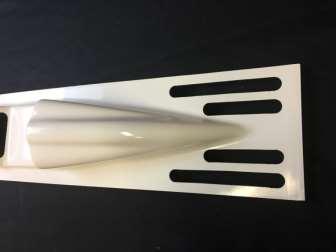
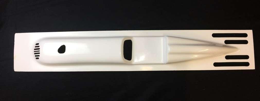
35 Cowling The SLR Missile features a one piece fiberglass cowling. It requires only sanding and adding two small wood formers. Sand the side edges so that they are straight and even. Be sure to sand enough so that you are into the white gel coat. Sanding cowling edges. Sand well. Sand the bottom of the cowling at the front and rear with 80 grit paper. This provides a good surface for the cowl formers. Use waxed paper and put the forward cowl deck former in place with its 3/16 dowel. The waxed paper will prevent the former from being glued to the boat. Use small clamps inside to hold the former flush with bulkhead 1. Do not glue in the dowel until after the decks are on. Waxed paper at front cowl former. Do the same with the rear former, only use small clamps to hold it slightly above flush. Use waxed paper. Set the cowl in place and center it on the deck support strips. If all is well, put epoxy on the front and rear deck formers and set the cowl deck in place. Use only a small amount of epoxy. We don t want it to run. The idea is to NOT glue the cowl to the boat. Be sure that the deck is flush with bulkhead 1 and centered on the deck strips. There will be some overhang at the rear. Scrap wood used to hold rear former in place. 35

 in front of bulkhead 1, and flush with the top. The deck center will sit on this.")

36 Clamp the cowl deck completely along both sides and against the deck formers. Double check that everything is in contact and allow to dry for several hours or overnight. Gluing front cowl former. When cured, sand the rear of the cowl deck flush with the transom. Remove the clamps and remove the cowl assembly. Reinstall the cowling and sand the front flush with bulkhead 1. If you have any leftover epoxy in the next steps, use some to create a small fillet on the cowl formers. Only put a fillet on the BACK of the front former and the FRONT of the rear former. If not, the cowl won t fit. Rear cowl former in place. Glue the forward deck center support (DCS) in front of bulkhead 1, and flush with the top. The deck center will sit on this. Seal this with epoxy when you can. You must provide cowl flotation, as fiberglass does not float. It s not a question of if you will lose your cowling, it s when Use foam and epoxy to glue it into the cowling. Foam floatation and air baffle in place. You must block the air from blowing straight through the cowling, by diverting it down, and over the exhaust before it can exit. See last page for a diagram of the air flow needed. 36


37 Do this with a piece of foam, sanded to conform to the inside of the cowling, just at bulkhead 3. We will be cutting air holes in the front of the cowling, and an air exit where the dashboard would be. Air baffle in place. Coat with epoxy. If we didn t have an air dam, the air would come in the front of the cowling, and sail straight through to the air exit, carrying very little heat with it. We need it to go into the front, and go around the bottom of the hull, before going up to the dashboard and rear air exit. Top Deck The Bullitt deck is done in 5 pieces; Two deck sides, two sponson decks and one deck center. It is important that you test fit and fully understand how the deck fits on before you epoxy. Decks ready to seal. All decks should already have 2 coats of epoxy on one side. If not, get it done. The deck halves are attached, allowed to cure, and the center deck is attached at the front. The sponson decks are done last. The cowling covers most of the open center section. Sand the top of the bulkheads so that the tabs are gone, and the bulkhead has a nice curve down to the side stringer. Use your plane to bevel the side stringer. Top decks taped in place. Before you glue anything, lets test fit the decks. 37


38 Put the cowling in place. Draw a line on each side of the cowling. These lines should trace the cowl on each side, marked on the deck supports. Remove the cowling. Using a couple of small clamps, clamp one deck to the deck support near the front and rear. Use masking tape, tape the rear portion of the deck down. Tape at the transom too. Marking decks for cowling. Continue taping the front portion. Make sure that the inside edge of the deck covers your line on the deck support. If all looks well, make an alignment mark on the deck and deck support. This will make it easier to line up the deck when you are gluing it in place. Set the cowl in place and trace directly onto the decks. One deck in place being marked for trimming. These will be your trim lines. Trim the deck to these lines. You will now align the pre-cut decks to the lines you drew on the deck supports. For the deck installation, make sure that the hull is sitting on your flat work surface. If the hull is twisted, the deck installation will lock it in that position. Weight the hull down so that it remains straight. You will need a small glue brush for the next steps. Deck being glued in place with epoxy. Mix about 1/2 ounce of 30 minute epoxy. Use your brush to coat all areas that this deck will touch. Bulkheads, stringers and deck support. Work quickly. Paint a thin coat of epoxy onto the deck perimeter. As soon as everything is ready, start clamping and taping the deck as before. Use your alignment mark to save time. 38


39 You can clamp to the sponson deck supports (SDS) near the front. Tape the crap out of the deck, make sure it is completely attached, allow to cure at least 3 hours and repeat the procedure on the other side. Do whatever necessary to clamp 100%. Make sure the hull stays weighted on the bench until all decks are cured. Glue the 3/16 dowel to the front of the cowl. Do not glue the cowl to the boat! Once all decks are cured, fit and glue in the deck center with 30 minute epoxy. The deck center should cover the deck center support glued to bulkhead 1. Tape tightly in place. Let sit for at least 3 hours. We used a couple of clamps made from 3 inch PVC pipe, sliced into rings about an inch wide with about 1 inch cut out. Deck center fitted and glued. Sand the tops of the bulkheads and DS parts. Bevel the forward non trip sheeting to accept the sponson decks. Glue the sponson decks on the same way. Test fit the decks into the 1/16 slots. Adjust the tabs as needed. Try to get a nice tight fit with the sponson decks. You can cut the top center of all bulkheads (2, 3, 4 and 5) off at this point. Cut just to the deck supports. Sand and seal the cut areas. Sponson deck being glued. 39


40 Cowl Latch Put the cowl in place and drill a 1/8 inch hole where marked on the transom. Drill through the transom and the rear cowl former. Hold the cowl down and drill slowly. Remove the cowling and drill the hole in the transom ONLY to 13/64 inch. Drilling cowl former 1/8 inch. The latch should go all the way in until the body is almost flush on the inside of the transom. This gives the latch maximum penetration into the cowl former. Test the fit of the hatch latch, but do not glue in until the boat is painted. Drill transom only to 13/64. Latch installed, but not glued. Latch pressed in. Don t glue until paint. 40


41 Radio Box Put the radio box on your marks, and be sure that your throttle pushrod seal does not interfere with bulkhead 3. If it does, move the radio box slightly to the left. Try to maintain at least 3/8 inch clearance from the pipe. You can epoxy the box in place or bolt it in. Radio box in place. If you bolt it in, use bolts, washers and nuts with the nuts inside the radio box. We use 3. Attach the throttle pushrod to the throttle bellcrank and to your throttle servo. Bend the pushrod as needed. Hook up the throttle and rudder pushrods. Water Supply Lines The holes in the bulkheads are sized for DuBro XL silicone tubing. We use it from the rudder to the engine. Make sure that the holes are not too small from epoxy. Route the water lines to the lowest fitting first. In low and out high. This pushes air out of the system. Cooling lines in place. Finishing Remove everything from the hull. Sand the entire hull with 80. Fill any dings, dents, craters, valleys or chips with wood filler. When dry, sand again with 180. Check to make sure that all imperfections are filled. If not, fill and sand again. Spend a little time getting this right, as it will make your boat look so much better when done. 41

42 Blow off the hull with compressed air, or use a vacuum to get the dust off. Mix about 1 ounce of finishing resin. Use a credit card to spread out the resin on the top and sides. Squeegee as much as you can. Get a thin even coat of resin on all areas. Use a small acid brush to get the edges. Scrape as much resin as possible. You just want to wet the wood with resin, any excess will just have to be sanded off later. This first coat is easy, as the wood will darken as it gets wetted with resin. The second coat will be a little more challenging, but will use far less resin and be faster to cover. When you are sure that all areas on the top and sides are covered, let it cure overnight. When cured, scrape the epoxy with a new utility knife blade. Hold it straight up (90 degrees to the surface). When done, blow the dust off and do the bottom. Repeat the whole thing for the second coat, Scrape the second coat and sand any corners lightly with 180. Wipe the hull down with alcohol or degreaser designed for paint. Use a tack cloth lightly to remove any dust. Spray a light coat of primer. Let this flash for a few minutes, and spray a heavy coat on. Let sit overnight. 42


43 When the primer is dry, use spot putty to fill any nicks or surface imperfections. When dry, wet sand with 220 on the rubber block. If you are happy with the surface, spray on another medium coat of primer. When dry, wet sand with 600 or 800. White primer and red spot putty. Use compressed air or a vacuum to remove the dust on the inside and outside of the hull. Wipe down the entire boat with alcohol. Use a tack cloth to lightly wipe all surfaces. Spray your color coats. When cured, wet sand with and clear coat the entire hull. Make sure the clear is completely cured before final assembly. Apply your decals. Wipe the area with alcohol, allow to dry. Remove the backing from the decal. If you have trouble removing the backing, press or squeegee it firmly, and try again. Align the decal and press firmly to surface. Roll or squeegee in place. Remove transfer sheet from top of decal. Spot putty fills the little imperfections. Final assembly Before you bolt anything to the hull, give it a good coat of paste wax. Don t wax the bottom. Sand the bottom of the sponsons with wet. Just remove the gloss. Sand in the direction of travel. Put the boat on your stand. This is where it will live, when it s not in the water. 43 Push the strut to the table so that it is flat on the table while the transom is 1-1/4

44 Sharpen the turn fin. Using a file (or grinder) and 220 grit paper, sharpen the right side of the turn fin only. The front and bottom should be sharp, and the back flat. Put the turn fin in its mount, and bolt it onto the sponson with the ¼-20 screws, into the blind nuts. Install the engine. We install the engine with pipe and carb attached. It takes some pressing and wiggling, but it will go. Install the radio box. Install the shaft tube. Install the strut, pushing the end of the shaft tube all the way in. Leave the strut loose in the brackets. Put the boat on a flat surface. You can hang the turn fin over the side of the table. Block up the transom 1-1/4 inch from the table. Tighten the strut in the brackets. Install the rudder assembly Install the flex shaft. Install the fuel bag and fuel lines. Install water outlets. Install water lines. Push the rudder and throttle pushrods through the pushrod seals. Attach both ends of the pushrods, making sure the seals are on the outside of the radio box. Make sure all your water lines are firmly attached. Use those teeny little tie wraps at each fitting. Center of Gravity The CG is very important. The CG is at bulkhead 3. Check the CG with everything installed and no fuel in the tank. To check the CG, pick the boat up with one finger on each side of bulkhead 3. The boat should balance within ½ inch of bulkhead 3. If it is tail heavy, add as much weight as necessary to balance. Don t worry about the weight. The boat can handle it. This is critical. If the CG is any farther back, the boat will blow off the water at high speeds, as well as hop in the turns. Be sure to leave at least 3/8 inch gap here. 44
45 Running If you are using a new engine, you should run it on the stand before going to the pond. This will do several things; It will allow the engine to loosen up a little, making starting a simple matter, as well as get YOU familiar with its starting and running characteristics. When new, the engines are very tight, and starting is difficult at best. Under no circumstances should you ever run a marine engine for an extended time without cooling water. Use our 3521 garden hose adapter. If you are going to run the boat on the stand, take the prop off, but leave the shaft connected to the engine. This will help to break in the strut bushings. At the pond Make sure your transmitter and receiver batteries are fresh, or fully charged. Do a range check with your transmitter antenna down, and note the distance. You should do a range check every day that you run. Should a problem arise, you can fix it before you damage anything. Tape the lid on the radio box with radio box tape. Regular tape leaves a residue. Make sure that your prop is sharp and balanced. Make sure all screws and nuts are tight. You can give it a little gas as it gets to the water, but not too much. Most people don t like getting sprayed with water Let the engine warm up for 30 seconds or so before giving it full throttle. Drive past yourself, and make sure you have a stream of cooling water. If you don t see any, bring it in pronto! If all looks good, hit it! Notice how the boat rides in the straights. Does it lean or pull to one side? Is the deck and transom level? How about the turns? Does the transom rise or fall in the turns? Does it slide or hook? It s a good idea to have a helper write down your comments as you run the boat. After the run, you can use the included Hydro Tuning Tools sheet to help you sort out any problems. We appreciate you buying this kit and hope that you enjoy it as much as we do! If you need any help with any aspect of this kit, please contact us via of phone. support@zippkits.com Toll Free (866) Fill the tank; turn on your transmitter, then receiver. Wiggle the rudder so you know it works, and then start the engine. Don t rev the engine much, as there is no load on the prop until it s in the water. To launch, have a helper toss the boat in level. 45
46 Troubleshooting Boat bounces in the straights- Boat blows over at high speed- Strut too high CG too far back Speed too slow CG too far back Strut too high Boat plows - CG too far forward Strut too low Strut negative Boat is very light and unstable- Strut too high CG too far back Boat needs left trim to go straight- Prop walk Prop walk Prop walk Turn fin not aligned correctly Prop walk Boat slides too much in turns- Boat hooks in turns- Boat dances in the straights Boat hops Turn fin bent Turn fin too small Turn fin fell off! CG too far back Rudder servo weak Lateral (side to side) balance off Pretty cool, huh? CG too far back or too much lift in prop Boat is slow and won t turn- Get a Zippkits boat! 46
47 Tuning notes The SLR Missile is just like any 3 point hydro, as far as tuning and adjustment. There are a few things that you should know when you are tuning your boat for maximum performance. The most important thing is to understand blow overs. Blow overs can only occur if the angle of attack gets positive. Angle of attack is the angle that the boat hull strikes the air. Since the bottoms of our hydros are flat, we use that for a reference point. The turn fin can have a strong influence on angle of attack if it is not aligned properly. Also note that this hull is designed to turn right. Left corrections can be made at full throttle, but due to prop rotation, left turns are not pretty. Remember that if you don t allow the nose to come up, the chance of blowing over is greatly reduced. Be aware of wind conditions and always watch the nose of the boat. If it starts to rise, let off the throttle slightly to settle it. The Missile does not warn you before it blows over, so you must watch the nose, especially when running into the wind. Turn Fin: Start with the turn fin parallel with the top of the bracket. Run the boat, and test. Angle the fin so that the bottom is very slightly kicked forward and try again. Repeat this process until the boat climbs up on the turn fin when you give a left correction. The ideal turn fin position is slightly back from this. You want the fin bottom as far forward as possible, without the boat climbing the fin with left rudder. 47

48 48


49 Carb bellcrank and carb arm in place. Optional 3558 aluminum arm shown. Bellcrank pushes arm open. Throttle spring closes. Deck support trimmed for carb clearance. Makes installing complete engine easier. 49
50 Cowl vent templates. 50
Super Sport. Building Instructions Z I P P M A N U FA C T U R I N G. A Zippkits RC Boat. 46 inch Gas Mono Hull
 SS Z I P P M A N U FA C T U R I N G Super Sport 46 inch Gas Mono Hull A Zippkits RC Boat Building Instructions 2018 JMP Hobby Group LLC Indiana USA (866) 922-9477 www.zippkits.com 1 D E S I G N C U S T
BUILDING INSTRUCTIONS
 Z I P P M A N U FA C T U R I N G A Zippkits R/C Boat BUILDING INSTRUCTIONS 2010 Zipp Manufacturing Frankfort, New York 13340 www.zippkits.com Table of Contents Introduction 1 Engine Mounting 30 S E C T
SEADUCER BOATS GAS SPORT HYDRO
 SEADUCER BOATS GAS SPORT HYDRO COME VISIT US ON THE WEB AT WWW.SEADUCERBOATS.COM 2 - Pkg. Of 440 push rod ends 2 - Pkg. of solder-on rod ends 2 -water outlet fitting 1-1/4" prop nut 1 -.250" x 30" flex
Tugster. Tug Boat. Competition or Sport Tug Kit. A Zippkits R/C Boat. Building Instructions
 Z I P P M A N U FA C T U R I N G Tugster Tug Boat Competition or Sport Tug Kit A Zippkits R/C Boat Building Instructions 2016 JMP Hobby Group St. Paul, Indiana 47272 www.zippkits.com Toll Free (866) 922-ZIPP
SEADUCER BOATS GAS MONO COME VISIT US ON THE WEB AT
 SEADUCER BOATS GAS MONO COME VISIT US ON THE WEB AT WWW.SEADUCERBOATS.COM 1 - Pkg. Of 440 push rod ends 1 - Pkg. of solder-on rod ends 2 -water outlet fitting 1-1/4" prop nut 1 -.250" x 24" flex shaft
Blazer Marine, Whiplash Sport 40
 Blazer Marine, Whiplash Sport 40 Thank you for choosing to build the Whiplash 40. We have spent over 12 years perfecting this design, and finally we are making it available to the world. We are excited
Blazer Marine, Whiplash Sport Hydro
 Blazer Marine, Whiplash Sport Hydro Thank you for choosing to build the Whiplash Sport Hydro. We have spent over 12 years perfecting this design, and finally we are making it available to the world. We
1/10 th Scale 1956 Ted Jones Classic Hydroplane
 1/10 th Scale 1956 Ted Jones Classic Hydroplane Preparation These plans show outside sheeting of 3/32 balsa laminated with 1/64 birch ply. This makes a light and strong skin for this boat. Optionally you
PAY N PAK, 1/12 th Scale, Limited Sport Hydro P Sport Hydro
 1980 82 PAY N PAK, 1/12 th Scale, Limited Sport Hydro P Sport Hydro Introduction: The 1980 turbine Pay N Pak is a good subject for a model race boat. It has a low profile, mild pickle-fork setback, long
Step 1: Block sand the transom to remove the seam joint. The end result should be a flat transom without a ledge where the seam joint is.
 WhiplashGV Instruction Manual Email: Brian@Blazermarine.com Phone: 513-598-1769 Step 1: Block sand the transom to remove the seam joint. The end result should be a flat transom without a ledge where the
Surfboard Repairs Chapter 7
 Surfboard Repairs Chapter 7 The Complete Surfing Guide for Coaches - Bruce "Snake" Gabrielson Repair Problems Boards continuously get bumped, hit rocks, break fins, get dropped, and many other things that
WHITE WOLF. X-ray View MID POWER MODEL ROCKET KIT BUILDING INSTRUCTIONS KIT SPECIFICATIONS:
 WHITEWOLF-38 PARTS LIST 1 - Nose Cone 1-17" Airframe 1-6" Motor Tube 3 - Aft Fins 3 - Forward Fins 2 - Centering Rings 1-15" Parachute 2 - launch lugs 1-12 Kevlar Shock Cord 1 - Motor Retention >>(screw/washer)
aero naut Electric Model Aeroplane Quido Order-No. 1303/00
 aero naut Electric Model Aeroplane Quido Order-No. 1303/00 Quido is a small model that accompanies you wherever you go. The prefabricated parts are mostly balsa and just need to be assembled according
Pre-Paint>Fuselage>Empennage>Fit vertical tail fin. Objectives of this task: Materials and equipment required: Fit the spar extender
 Pre-Paint>Fuselage>Empennage>Fit vertical tail fin Objectives of this task: To fit the vertical tail fin to the fuselage, including fitting the static probe, static tube, optional strobe light wiring and
We hope you ll enjoy the Drifter as much as we have! Scott DeTray Model Aero Specifications:
 We are excited to bring you the Drifter RC airboat. You re probably thinking it doesn t fly so what is Model Aero thinking??? We have always liked RC vehicles of all types and have had a fondness for airboats
Constitution Instructions
 Constitution Instructions This kit will build a 1:48 scale hull for the USS Constitution frigate. The kit contains the following parts. 1/8 deck with laser etched deck lines 1/8 railing Ribs Center keel
Bladerider X8 Assembly Help Notes
 2.1 Remove All Parts & Have Some Tools Handy Remove all items from the box and identify each part as per the packing sheet and check that nothing is missing. If there is something missing, please email
General Build Instructions for Mach 1 BT50 and BT55 Single Fin Kits. Needed Items for Assembly
 General Build Instructions for Mach 1 BT50 and BT55 Single Fin Kits 60-80 grit sandpaper Hobby knife Tape measure Scissors CA Super glue 30-minute epoxy 5-minute epoxy Masking tape 1/16 drill bit Needed
Dornier Do R 4 Super-Wal
 Dornier Do R 4 Super-Wal Model Aviation Laddie Mikulasko s Dornier Do R 4 Super-Wal Build the multiengine, record-setting seaplane. Article, plans, instructions, and photos by Laddie Mikulasko. Complete
INSTALLING YOUR CLC RUDDER
 INSTALLING YOUR CLC RUDDER These instructions are written to help you install the CLC rudder kit on your wooden kayak. The rudder can be fitted to your boat during construction or after completion. Please
ANGEL 2000 glider ARF ASSEMBLY MANUAL. Specifications: MS: 129
 WWW.SEAGULLMODELS.COM ASSEMBLY MANUAL ANGEL 2000 glider Graphics and specifications may change without notice. MS: 129 ARF Specifications: Wingspan---------------78.7 in ( 200cm). Wing area---------------582.8sq.in
Miss Mayflower. Build Manual
 Miss Mayflower Build Manual Thank you for the purchase of the Miss Mayflower, this new exciting craft will give you fun on many types of terrain including snow, gravel, pavement, grass, water, and when
AGM 33 PIKE ALL FIBERGLASS. Specifications Length: 92 Diameter 5.5 Weight: 24 lbs Motor Mount: 75mm Fins: 6-3/16 G10 CP: 68 from nose tip Parts List
 ALL FIBERGLASS AGM 33 PIKE Specifications Length: 92 Diameter 5.5 Weight: 24 lbs Motor Mount: 75mm Fins: 6-3/16 G10 CP: 68 from nose tip Parts List (1) Filament Wound Nose Cone w/ Metal Tip (1) Nose Cone
aero naut Order No. 3009/00
 aero naut Order No. 3009/00 Introduction: The model should be assembled following the sequence of the stages of construction described in these instructions. The laser-cut components are individually numbered.
Soling Building Tips II
 Soling Building Tips II Prepared: Arthur Deane Jan 20, 2002 adeane@ic.net Introduction The following are some lessons learned and experience gained in building a Soling kit. The plan developed is based
MiniTwin by Acer
 MiniTwin 250 - by Acer ASSEMBLY INSTRUCTIONS Thank you for choosing the MiniTwin 250 as your next project. This kit is easy to build and only requires a few hours to complete. Once finished, you will be
Pitts Model 12 Wing Leading edge Installation
 Pitts Model 12 Wing Leading edge Installation This procedure is used to install molded plywood leading edges included in the Pitts Model 12 kit. Nine (9) molded leading edge section are require per aircraft;
8-GUN CORVETTE ASSEMBLY INSTRUCTIONS
 8-GUN CORVETTE ASSEMBLY INSTRUCTIONS THE HULL STEP 1 Fasten the Deck to the Hull. Find the hull. This is a large, pink, ship-shaped piece of insulating foam board. This will form the base of your model
AVA Building Instructions
 Suggested Assembly Sequence: AVA Building Instructions 1. Insert fittings in rudder and trial fit rudder on boom 2. Attach stab to v-mount and position ahead of rudder ¼, sanding the v-mount as needed.
Grandpa's Homemade Rocket for About a Dollar!
 Grandpa's Homemade Rocket for About a Dollar! Grandpa and Granny Co. 2012 The most common items needed: (The number of Rocket parts from each item is before the parts name and its proportionate cost is
FlyingFoam Nurf. General Assembly Instructions
 FlyingFoam Nurf General Assembly Instructions These instructions apply to the Nurf, an all EPP forward swept flying wing available from FlyingFoam.com. Building and operating a remote controlled aircraft
TABLE OF CONTENTS FRAME FEATURES INTRODUCTION
 S3 DISC MANUAL TABLE OF CONTENTS Introduction...1 Frame Features...2 Fork Preparation...3 Small Parts...5 Frame Preparation...6 Brake Housing Installation...7 Mechanical Cable Routing...9 Electric Cable
Hip Block Installation Instructions:
 Hip Block Installation Instructions: The instructions that follow are shown for our low profile hip blocks installed in a Storm Chaser M C-1. However, the very same technique can be used for any of our
SECTION 10iS: TAILCONE
 VAN'S AIRCRAFT, INC. F-1282-R BOTTOM RIGHT SKIN F-1283C J-STIFFENER F-1278 TOP SKIN F-00009-L ADAHRS BRACKET F-00009-R ADAHRS BRACKET F-1279-R UPPER RIGHT SKIN F-1280-R RIGHT SIDE SKIN SECTION 10iS: TAILCONE
F-1279-R UPPER RIGHT SKIN F-1280-R RIGHT SIDE SKIN F-1281-R LOWER RIGHT SKIN F-1208-R FUSELAGE FRAME
 F-1282-R BOTTOM RIGHT SKIN F-1283C J-STIFFENER F-1278 TOP SKIN F-00009-L ADAHRS BRACKET F-00009-R ADAHRS BRACKET F-1279-R UPPER RIGHT SKIN F-1280-R RIGHT SIDE SKIN SECTION 10: TAILCONE F-1279-L UPPER LEFT
2019 MADONE ASSEMBLY MANUAL
 2019 MADONE ASSEMBLY MANUAL 2019 MADONE Rim brakes and Di2 drivetrain Rim brakes and mechanical drivetrain Disc brakes and Di2 drivetrain Disc brakes and mechanical drivetrain TABLE OF CONTENTS Common
Vacuum Bagging Wings Instruction Manual Purdue University
 Vacuum Bagging Wings Instruction Manual Purdue University Note: Do not leave the vacuum pump running unattended! Revision: Original Release 10/31/15 Vacuum bagged wings are quick to build, light weight,
Akcent-2 - Building Instructions
 Akcent-2 Home Pictures Building Instructions Ordering Akcent-2 - Building Instructions Note! The pictures show older kits with "diser" wings. The new kits come with nicer D-box wings. Servo locations are
Fiber Optic Lighted Bubbler Spillway Pot (DLP-45) Installation Manual
 Installation Manual") Fiber Optic Lighted Bubbler Spillway Pot (DLP-45) Installation Manual 27.75 23.75 25.50 20.75 Specifications: 8-13 GPM 100 strand fiber - Bubbler 75 strand fiber - Spillway Light Bar 45 ft. fiber tail
Fiber Optic Lighted Bubbler Spillway Pot (DLP-45) Installation Manual 27.75 23.75 25.50 20.75 Specifications: 8-13 GPM 100 strand fiber - Bubbler 75 strand fiber - Spillway Light Bar 45 ft. fiber tail
FRAME FEATURES TABLE OF CONTENTS INTRODUCTION
 R3 MANUAL TABLE OF CONTENTS Introduction...1 Frame Features...2 Fork Preparation...3 Small Parts...5 Frame Preparation...6 Mechanical Cable Routing...7 Electric Cable Routing...9 Seatpost Assembly & Installation...11
MICRO - DLG. This kit should only take 30 minutes to compile, very simple and quick.
 MICRO - DLG This kit should only take 30 minutes to compile, very simple and quick. You will need: Hot Glue ( small tip preferably ) Sharp razor blade Ruler a strip of strong fiber tape Thin nose Pliers
Trim Tab Wind Vane for boats with transom mounted rudders
 Trim Tab Wind Vane for boats with transom mounted rudders If your boat has a transom mounted rudder, you can build this self-steering windvane for around $150, using regular wood working tools and some
Below are the instructions to build a roller-furling unit for under $10. Read the entire process before beginning the project.
 Greg Cowens' $10 PVC Roller Reefing for CP-16's by Greg Cowen Below are the instructions to build a roller-furling unit for under $10. Read the entire process before beginning the project. Materials: 2
2019 MADONE ASSEMBLY MANUAL
 2019 MADONE ASSEMBLY MANUAL 2019 MADONE Rim brakes and Di2 drivetrain Disc brakes and Di2 drivetrain Rim brakes and mechanical drivetrain Disc brakes and mechanical drivetrain TABLE OF CONTENTS Common
Carving a Custom Seat
 Carving a Custom Seat Seat Carving your own seat from mini-cell, high-density foam is really quite simple and has proven to be more comfortable than any commercially produced seat and often more reasonably
CONSTRUCTION OF A GUNBOAT A CLASS YACHT by Brian Dill
 CONSTRUCTION OF A GUNBOAT A CLASS YACHT by Brian Dill The Gunboat design is the latest Radio A class from Graham Bantock, optimised to provide the best boat speed below 4 knots and to be as good as possible
(PLEASE CONTACT YOUR LOCAL DEALER or CUSTOMER SERVICE FOR WARRANTY INFORMATION)
") RUDDER KIT SOLO KAYAKS IMPORTANT: Tandem models will require the Wildy Supplemental kit in addition to this kit. The Supplemental kit provides extension straps and extra footbraces that allow rudder positioning
RUDDER KIT SOLO KAYAKS IMPORTANT: Tandem models will require the Wildy Supplemental kit in addition to this kit. The Supplemental kit provides extension straps and extra footbraces that allow rudder positioning
Aliphatic Resin Wood Glue. 18" Fabric Parachute Part #PNC50 Part # Part #11700 Part #J0016. Launch Lug
 ADANCED * What you will need to build the Quest High-Q Hobby Knife * Straight Edge Pencil Aliphatic Resin Wood Sanding Sealer & Brush Spray Paint Parts and exploded view of the Quest High-Q Nose Cone 18"
Hat s off to you for choosing a kit from Port Townsend Watercraft.
 Hat s off to you for choosing a kit from Port Townsend Watercraft. 1 A 30 year fascination with the challenges of nesting boat design, and many prototypes have led to the PT Eleven. Because you chose this
Model Aero Sportster Indroduction
 1 Model Aero Sportster Indroduction We are excited to introduce the Model Aero Sportster! Inspired by classic designs of the past, the Sportster is a relaxing slow flyer, equally at home indoors or outside
R5 RIM MANUAL EN. Version 1 I
 R5 RIM MANUAL EN Version 1 I 28.04.2017 TABLE OF CONTENTS Introduction...1 Frame Features...2 Fork Preparation...3 Small Parts...5 Frame Preparation...6 Mechanical Cable Routing...7 Electric Cable Routing...9
R3 RIM MANUAL EN. Version 1 I
 R3 RIM MANUAL EN Version 1 I 07.02.2017 TABLE OF CONTENTS Introduction...1 Frame Features...2 Fork Preparation...3 Small Parts...5 Frame Preparation...6 Mechanical Cable Routing...7 Electric Cable Routing...9
EPP Version Building Notes Updated
 EPP Version Building Notes Updated 12-10-2013 The Zulu covers a wide range of flying conditions: slope soaring in light to strong lift, thermalling, aerobatics, discus launches, and combat; for skill levels
INSTRUCTIONS FOR GLUING ON THE BUMPER FOR PORT TOWNSEND WATERCRAFT S NESTING DINGIES. (Or requires a 1 surface to adhere to.)
") INSTRUCTIONS FOR GLUING ON THE BUMPER FOR PORT TOWNSEND WATERCRAFT S NESTING DINGIES. (Or requires a 1 surface to adhere to.) The PT 11 bumper is made from a high quality, non marking EPDM rubber. This
INSTRUCTIONS FOR GLUING ON THE BUMPER FOR PORT TOWNSEND WATERCRAFT S NESTING DINGIES. (Or requires a 1 surface to adhere to.) The PT 11 bumper is made from a high quality, non marking EPDM rubber. This
In each step, the needed parts are shown the number right below. Locate all parts for the step.
 Tools Required for Assembly Phillips Screwdriver, Med Needle Nose Pliers Sandpaper (#400 grit) Hobby Knife Scissors CA Instant Glue Rubbing Alcohol Drill Bit 1/16", 1.6mm 5/64, 2mm 1/8, 3mm 5/32, 4mm Before
Stand-N-Fish FULL DETAIL INSTALLATION INSTRUCTIONS
 1 Stand-N-Fish FULL DETAIL INSTALLATION INSTRUCTIONS Thank you for purchasing the incredible new Stand-N-Fish Kayak Fishing System. Once installed on your kayak the Stand-N-Fish will take your kayak fishing
ASSEMBLY INSTRUCTIONS
 ASSEMBLY INSTRUCTIONS Ballpark Classics Baseball Game MLB Edition Figure B Read the instructions completely before beginning g assembly. You will need a Phillips screwdriver. 1. Remove the game from the
Horizontal Fuselage. Top Vertical Fuselage 1. Lay out the Top Vertical Fuse Front(1), Top Vertical Fuse Back(2), and Vertical Stabilizer(3).
, Top Vertical Fuse Back(2), and Vertical Stabilizer(3).") Rumbuilder 71 B-17 Congrats on your Rumbuilder B-17! We re glad you chose to fly with us! If you have any problems, or missing/broken kit pieces, please contact us. We d be happy to replace any damaged
Rumbuilder 71 B-17 Congrats on your Rumbuilder B-17! We re glad you chose to fly with us! If you have any problems, or missing/broken kit pieces, please contact us. We d be happy to replace any damaged
Et's Skeg: the full story
 Et's Skeg: the full story Having used pie-slice skegs on mass-market boats with big floppy slots and finding them ok, but not ideal, I researched a bit online looking for a skeg or skeg design for my North
Your kit contains the following items. Additional Items You May Need. Pre- cut parts Propeller rigging and rubber Sandpaper Covering sheet
 Your kit contains the following items Pre- cut parts Propeller rigging and rubber Sandpaper Covering sheet The SkyFox offers great glide performance in a rubber powered plane due to its built up wing.
ANATOMY OF FUSELAGE REPAIRS
 ANATOMY OF FUSELAGE REPAIRS The first part of this file is about doing a repair on the glassed-over fuselage. The latter part covers some repairs on composite fuselages. The glassed-over fuse will stand
Model Aero AT-6 Texan Introduction
 1 Model Aero AT-6 Texan Introduction We are excited to introduce the Model Aero AT-6 Texan! Originally used as an advanced trainer by the U.S. Armed Forces, the AT-6 is a relaxing slow flyer, equally at
TABLE OF CONTENTS INTRODUCTION
 R3 DISC MANUAL TABLE OF CONTENTS Introduction... 1 Frame Features... 2 Fork Preparation... 3 Small Parts... 5 Frame Preparation... 6 Brake Housing Installation... 7 Mechanical Cable Routing... 9 Electric
Falcon 3 145, 170, 195 and Tandem Owner / Service Manual
 Falcon 3 145, 170, 195 and Tandem Owner / Service Manual January 2007 - Second Edition Removing The Sail From The Airframe And Short Packing The Glider Many maintenance and repair procedures will require
RUDDER KIT INSTRUCTIONS
 C I N S T R U C T I O N S RUDDER KIT INSTRUCTIONS PAMLICOS-0,0,T, T, 60T, Excel Rotomolded Pamlico 0, 0, T, T, 60T, Excel The addition of a rudder to a kayak results in additional control and efficiency,
Building Instructions ME 163 B 1a M 1:5 Turbine
 Building Instructions ME 163 B 1a M 1:5 Turbine Thank you for choosing our kit of the Me-163B. We ask you to read the instruction once in advance before building this kit in order to avoid mistakes. Make
PT 11 trouble-shooting and maintenance.
 PT 11 trouble-shooting and maintenance. Does your rudder not stay down?...your back seat slip off?...your knobs tight and your leather pads loose? Maybe we can help. We have used our PT 11 s hard enough
CARL GOLDBERG PRODUCTS, LTD. P.O. Box 818 Oakwood GA Phone # Fax #
 Superfloats 36 ARF WARNING A radio-controlled model is not a toy and is not intended for persons under 16 years old. Keep this kit out of the reach of younger children, as it contains parts that could
Troyer s Gourd Rack 8 unit F R H O P
 B E A D I M-N L Vertical Parts F R H O P Horizontal Parts C G J Updated 11/16 Parts List A: Top of Pole B: Bottom of Pole C: 48 Ground Stake D: Top Perch rods 48 long E: Hub F: Rope Winder w/ attached
Trogear Bowsprit Through Hull Installation Manual
 Trogear Marine Products, LLC www.trogear.com info@trogear.com 866-616-2978 Trogear Bowsprit Through Hull Installation Manual Congratulations on your purchase of the Trogear Bowsprit which can be installed
Exxtacy. Repair and Tuning Manual. Exxtacy Construction Basics
 1 of 20 Exxtacy Repair and Tuning Manual Construction Basics D Cell Repair Rib Repair Tuning Exxtacy Construction Basics The Exxtacy is built with carbon fiber and Kevlar/Aramide honeycomb. The Exxtacy
Construction Chapters Index
 Construction Chapters Index 9 7 8 Chapters Index c. c. c. c. c. c. c7. c8. c9. c0. c. c. c. c. c. c. c7. Balsa Wood Skeleton Strip Planking Hull Fairing Keel Bulb Mould Lead Bulb Casting Keel Construction
Methylethycetone (MEC) - PMS 60 polyurethane glue - Grease - White silicone
 - PMS 60 polyurethane glue - Grease - White silicone") CHAPTER PLAN page : 1/8 SAILING BOAT SUSPENDED WITHOUT DECK BEARING SAILING BOAT SUSPENDED WITH DECK BEARING SAILING BOAT SUSPENDED WITH AUTOMATIC BEARING ALIGNMENT RUDDER SYSTEM FOR ANTARES MOTOR BOAT
CHAPTER PLAN page : 1/8 SAILING BOAT SUSPENDED WITHOUT DECK BEARING SAILING BOAT SUSPENDED WITH DECK BEARING SAILING BOAT SUSPENDED WITH AUTOMATIC BEARING ALIGNMENT RUDDER SYSTEM FOR ANTARES MOTOR BOAT
Contents. Stainless Steel Side Block. 1.1 Separating the Side Block. Stainless Steel Side Block Reassembly of. Assembly from the Helmet Shell
 Separating the Side Block Assembly from the Helmet Shell Contents SSB-1 SSB-3 SSB-5 SSB-5 SSB-7 1.1 Separating the Side Block Assembly from the Helmet Shell 1.2 Side Block Assembly Replacement 1.3 Defogger
Whisper 1400 Glider Operation Manual
 Whisper 1400 Glider Operation Manual Specifications: Wingspan: 55 (1400mm) Length: 32.5 (825mm) Wing area: 323 sq. in. Weight: 16 oz.(453g) Ace R/C Whisper 1400 Glider R/C Sailplane (4104-F) Distributed
CARL GOLDBERG PRODUCTS LTD.
 CARL GOLDBERG PRODUCTS LTD. P.O. Box 818, Oakwood, GA 30566 678-450-0085 Fax: 770-532-2163 www.carlgoldbergproducts.com copyright 2003 Carl Goldberg Products, Ltd. WARNING! THIS IS NOT A TOY! THIS IS NOT
STEP 1 A. Lay the two Motor Mount Tubes on a flat surface with ends even and Glue them together with White Glue. Allow Glue to set before moving on.
 Prod. No. A51003 Skill Level Three QUEST AEROSPACE, INC PO Box 2409 Pagosa Springs, CO 81147 800-858-7302 Things You ll Need To Assemble this Kit: Pencil and Hobby Knife: White Glue: Aliphatic Resin glue,
CONFER ABOVE GROUND CURVE STEP / ABOVE GROUND CURVE STEP SYSTEM ASSEMBLY AND INSTALLATION MANUAL
 SAVE THESE INSTRUCTIONS DEALER/INSTALLER: GIVE TO HOMEOWNER CONFER ABOVE GROUND CURVE STEP / ABOVE GROUND CURVE STEP SYSTEM ASSEMBLY AND INSTALLATION MANUAL Model CCX-AG Note: 40 lbs. of sand required!
Aegea Assembly Notes:
 Aegea Assembly Notes: The Aegea model is a thermal Duration (TD) model made up of components from Phil Barnes 1 (bagged wing and tail group) and Terry Luckenback 2 (Pretty Mantis fuse). Due to its construction
(PLEASE CONTACT YOUR LOCAL DEALER or CUSTOMER SERVICE FOR WARRANTY INFORMATION)
") RUDDER KIT SOLO AND TANDEM KAYAKS IMPORTANT: For Tandem kayaks, the Supplemental Kit will be needed in addition to this kit and can be purchased through a registered dealer. The addition of a rudder to
RUDDER KIT SOLO AND TANDEM KAYAKS IMPORTANT: For Tandem kayaks, the Supplemental Kit will be needed in addition to this kit and can be purchased through a registered dealer. The addition of a rudder to
Little Dog Dual Deploy
 Little Dog Dual Deploy John Wilke & Paul Fechtmeister September 2010 All dimensions are in inches unless specified Construction Notes: Other items you will need: One set of epoxy Motor One sheet of 120
QUALITY ALUMINUM BOAT LIFTS, INC. INSTRUCTIONS. Dominator Lake Lift
 INSTRUCTIONS Dominator Lake Lift PHONE:251-986-3882 * FAX:251-986-3136 QABLDOMINATORINST.2014 P a g e 1 Quality Aluminum Boat Lifts, INC. Installation Instructions: Dominator Lake Lift Thank you for your
FRAME FEATURES TABLE OF CONTENTS INTRODUCTION. A guide to your Cervélo C Series frame.
 C SERIES MANUAL TABLE OF CONTENTS Introduction...1 Frame Features...2 Fork Preparation...3 Small Parts...5 Frame Preparation...6 Brake Housing Installation...7 Mechanical Cable Routing...9 Electric Cable
RAVE SUP STAND UP PADDLE BOARD User Guide/Owner s Manual
 RAVE SUP STAND UP PADDLE BOARD User Guide/Owner s Manual ! W A R N I N G This product is not a lifesaving device. Always wear a nationally approved personal floatation device when using this product. Not
1982 Hydrostream Viking Restoration
 1982 Hydrostream Viking Restoration Part 2c: The Rebuild Daniel W. Rickey Winnipeg, Manitoba Canada daniel@cancercare.mb.ca 2000-09-22 Introduction Part one of this report showed how the shoddy manufacturing
VALDIVIA BUILD LOG Dr Ron
 VALDIVIA BUILD LOG Dr Ron The Robbe kit of the two-masted schooner Valdivia was purchased in 2007, along with the fitting set and propulsion accessories, and has been staring me in the face since then
Kari-Tek. Kari-Tek. Hydro Skeg Retro-Fitting Instructions. Instructions for retro-fitting of Hydro Skeg
 Kari-Tek Instructions for retro-fitting of Hydro Skeg A good knowledge of fibreglassing will be required to fit the Hydro Skeg successfully. When working with fibreglass and cutting the holes, safety glasses,
TOURNAMENT ICE. 8Ft-Gold Standard Manual Score Home Air Hockey Game Assembly Instructions / Manual
 TOURNAMENT ICE 8Ft-Gold Standard Manual Score Home Air Hockey Game Assembly Instructions / Manual Thank you for purchasing a Gold Standard Games product. All of us at Gold Standard Games want you to be
MODEL CCX-AG CURVE STEP / CURVE STEP SYSTEM
 To reduce the risk of drowning, entrapment, falls, paralysis, electrocution, or other serious injury or death: Dealer/Installer: Give manual to homeowner. Installer: Read "Safe Installation" on p. 2 and
Board Glassing Chapter 6
 Board Glassing Chapter 6 The Complete Surfing Guide for Coaches - Bruce "Snake" Gabrielson Glassing Guidelines Like shaping, there is probably any number of ways to successfully glass a blank. Yet there
SADfab Delrin Bushing Kit Installation Instructions For Mazda Miata
 SADfab Delrin Bushing Kit Installation Instructions For 90-05 Mazda Miata Kit Contents: Bushings: X4 FUCA delrin bushings (front upper control arm) X2 FLCA-f-f delrin bushings (front lower control arm,
8. Carefully layout all the parts of the reservoir setup and clean any dirt, grime or dust from the parts. ( image 8 ) 8
 8") INSTRUCTIONS TO SERVICE AMADAXTREME SHOCKS 2.0 REMOTE RES AUSTRALIAN VERSION PART 1 - SERVICE THE RESERVOIR 1.Prior to cleaning the shock check for any leaks or signs of damage to the res, lines, bushes
INSTRUCTIONS TO SERVICE AMADAXTREME SHOCKS 2.0 REMOTE RES AUSTRALIAN VERSION PART 1 - SERVICE THE RESERVOIR 1.Prior to cleaning the shock check for any leaks or signs of damage to the res, lines, bushes
How Scott Builds a Fighter Kite, May 2011 Updated Sept 2018
 How Scott Builds a Fighter Kite, May 2011 Updated Sept 2018 MAKE A TEMPLATE 1. Draw half sail plan on 17x22 pad with 4x4 (1/4 inch) grid. Add ¼ inch extra on nose (for reinforcement) and plenty of extra
Assembly Instructions. -Cantilever Boat Lifts
 Assembly Instructions -Cantilever Boat Lifts Winch Instruction Page Safety Information 1. The winch is built for the multipurpose of hauling and lifting operations. It is not to be used as a hoist for
Pakboats PakCanoe Assembly Instructions
 Pakboats PakCanoe Assembly Instructions Note: Please read these assembly instructions carefully before assembling the canoe. a A. Assembling the canoe Note: Don't be afraid to get into the canoe while
FIRST TEAM SPORTS, INC Storm Portable Series Assembly Instructions
 FIRST TEAM SPORTS, INC Storm Portable Series Assembly Instructions WARNING! WARNING! WARNING! THIS BASKETBALL SYSTEM IS SPRING LOADED AND SHIPPED UNDER TENSION. ATTEMPTING TO ASSEMBLE OR DISASSEMBLE ANY
TECH SHEET ORANGE PIVOT TOOL INSTRUCTIONS
 page 1 ORANGE PIVOT TOOL INSTRUCTIONS This is a guide of how to change the pivot bearings on an Orange frame with a bore style pivot axle. 4 8 Bore Type Pivot Axle Horiz-Hold Type Pivot Axle Please read
SPECIAL THANKS TO THE FOLLOWING PEOPLE FOR THEIR HELP IN THIS PROJECT!
 The Viper Mark VII is the state of the art fighter of the Colonial Fleet. It is sleeker and more modern than the Viper Mark II. The Mk7 is designed for both space and atmospheric environments and is also
HOME ASSEMBLY INSTRUCTIONS
 HOME ASSEMBLY INSTRUCTIONS This Papillionaire Bicycle now belongs to you. It will take you to work, wait patiently outside your local cafe, and carry your groceries home. This is the start of your long-term
REPLACING THE AFT RUDDER CABLES
 REPLACING THE AFT RUDDER CABLES Note: You must have the assistance of a qualified Aircraft Mechanic to perform this procedure. A logbook entry with the mechanics signature is required. Please read these