The Longitudinal Stability of the ZP2N-1 Airship
|
|
|
- Maria Edwards
- 5 years ago
- Views:
Transcription

1 Calhoun: The NPS Institutional Archive Theses and Dissertations Thesis Collection The Longitudinal Stability of the ZP2N-1 Airship Layton, Donald M. Princeton University

2
3
4
5


6 THE LONGITUDINAL STABILITY OP THE ZP2N-1 AIBSHIP by D. M. LAYTON anct E. F. IACOBELLI May 1954 Report No. 26k Princeton University School of Engineering Department of Aeronautical Engineering Submitted in partial fulfillment of the requirements for the degree of Master of Science in Engineering from Princeton University, 1954.
7 CPiesIs ^4


8 ACKNOWLEDGMENTS The writers of this report wish to express their appreciation to CAPT Ben May, USN, Commander of Naval Airship Training and Experimentation, who granted authorization to the writers to make flights In the ZP2N-1 airship. Further acknowledgment is made to CDE M. H. Eppes, USN and LCDE B. Levitt, USN, Senior Member and Secretary respectively of the Sub-Board of Inspection and Survey, U. S. Naval Air Station, Lakehurst, N. J Through their cooperation flights in the airship were made available during acceptance trials. The assistance of LCDE Levitt and LCDE P. 0. Carls tad, USN, In searching the files of the Sub-Board of Inspection and Survey was invaluable in the preparation of this report. 2$$.2S
9

10 SUMMARY A series of steady flight tests were made to determine the static longitudinal stability parameters of a U. S. Navy ZP2N-1 airship, and the results were compared with those computed from other considerations. It was found that the steady state flight test values agreed with the computed values. The major differences encountered were due to basic inaccuracies in the test procedure. It was found that the airship was slightly unstable at low angles of attack. The stability at high angles of attack is attributed to the weightbuoyancy force.

11

12 TABLE OF CONTENTS Introduction 1 PART I, SOURCES OP FORCES AND MOMENTS Aerodynamic Envelope Moment 4 Envelope Lift and Resulting Moment k Lift Due to Stabilizers and Resulting Moment 5 Drag and Drag Moment 6 Thrust and Thrust Moment 7 Weight and Buoyancy Force and Moment 7 PART II, FLIGHT TEST ANALYSIS Description of the Airship 9 Instrumentation 11 Flight Test Procedure 13 Flight Test Data Reduction 14 Presentation of Data 15 Discussion and Results 18 Conclusions and Recommendations 21 Tables of Data 23 Figures 31
13 V


14 THE LONGITUDINAL STABILITY OF THE ZP2N-1 AIRSHIP INTRODUCTION Non-rigid airships have been flown satisfactorily in various sizes and configurations by commercial and military activities for many years. During World War II and following, there has been a military airship program of no small stature by the U. S. Navy. Although there was some in-flight investigation of the longitudinal stability of rigid airships in the 1920' s, as far as Is known, there have been no attempts to quantitatively investigate the longitudinal stability of the non-rigid type from flight data. Subsequent to the late 1930 's there has been a dearth of published information concerning the stability of lighter-than-aircraft. Inasmuch as there is no aerodynamic difference between a rigid airship and a similar non-rigid except for the minor considerations of skin drag due to differences in outer fabric, the theories developed for rigid airships hold well for non-rlglds. Munk has established a reliable formula for the pitching (1)
15


16 moment of a body of revolution; however, there has been no suitable method of theoretically or empirically determining the lift force generated by a body of revolution. Further, present means, both theoretical and empirical, do not accurately apply to the stabilizing surfaces because of the extremely low aspect ratio. It was, therefore, proposed that this thesis should cover a modest attempt to investigate the static longitudinal stability of a U.S. Navy ZP2N-1 airship in flight with an aim to evaluate C, C and C ; to reconcile theory and practice; and to learn advantageous operating procedure. Donald W. Lay ton Eocco P. Iacobelli (2)
17

18 PART I SOURCES OF FORCES AND MOMENTS (3)
19

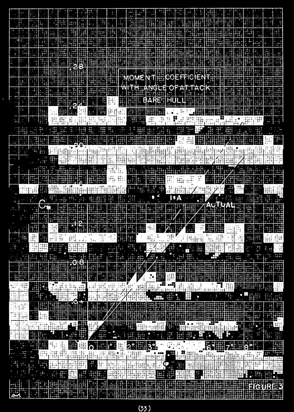
 Is 2 a function of fineness ratio. This aerodynamic moment taken at the center of volume is destabilizing in nature. Pig.")
20 AERODYNAMIC ENVELOPE MOMENT The resulting pressure distribution on a body of revolution moving in a fluid at an angle of attack gives rise to a sizable pitching moment. Dr. Max Munk in his classic paper, Ref. 3, developed the equation for this aerodynamic moment of a body of revolution at an angle of attack. M «Volume x q x (K 2 - K x ) sin 2 < where (K 2 - K^) is a factor relating the apparent mass of the air surrounding a cylinder to that of the apparent mass of the air surrounding an ellipsoid. (K - Kj_) Is 2 a function of fineness ratio. This aerodynamic moment taken at the center of volume is destabilizing in nature. Pig. 3 is a plot of C m versus or for a bare airship hull and demonstrates this Instability. ENVELOPE LIFT AND RESULTING MOMENT EFFECT A body of revolution In a perfect fluid experiences no lift with angle of attack. However, In a real fluid, an ellipsoid-type body of revolution developes vortices over the aft portion due to the separation of the flow. This vortex effect produces a lifting force acting at the rear of the body (Ref. 4). Compared with an airfoil where the lifting force acts at the center of pressure CO
21
«The lift developed by the envelope Is of the order of one percent of the lift of an airfoil of equal surface area (Fig. 4).")
«LIFT DUE TO STABILIZERS AND RESULTING MOMENT Fins and control surfaces are attached to an airship hull to Increase the dynamic stability and to provide for longitudinal and directional control.")
22 forward of the center of gravity thus creating an unstable moment, the lifting force on the bare hull of the airship generates a stabilizing moment (Fig. 3)«The lift developed by the envelope Is of the order of one percent of the lift of an airfoil of equal surface area (Fig. 4). The value of this lift is a non-linear function of angle of attack and must be determined from wind tunnel tests (Eef. 5)«LIFT DUE TO STABILIZERS AND RESULTING MOMENT Fins and control surfaces are attached to an airship hull to Increase the dynamic stability and to provide for longitudinal and directional control. The conventional location of these surfaces is on the after part of the hull. These fins are of necessity large in order to counteract the aerodynamic pitching moment. Because of their size, a relatively large lift force is produced. Usually symetrlcal airfoil sections are used. Due to the fact that the aspect ratio of the fins as conventionally computed is so small, the fins act more like wing tips than wing sections. An approximation to the variation of fin lift with angle of attack can be made from the equation: TtX b^ where S is the area of the fins plus the projection of (5)
23

24 the envelope between the fins, and b is the span of the fin-envelope combination (Bef. 2) Pin lift may be assumed to act at the quarterchord of the fin. This, then contributes a stabilizing moment to the airship equal to the product of this lift and its lever arm. For purposes of control, this stabilizer lift is augmented by elevator deflection (Pig. 5). The change In lift per degree of control deflection is a function of the ratio of elevator area to total stabilizer area. DRAG AND DBAG MOMENT The drag of an airship can best be determined from wind tunnel tests (Pig. 6), but can also be determined In level unaccelerated flight tests by equating thrust to drag. This assumes an accurate evaluation of thrust. Since the profile and skin drag compose the major portion of the drag force, and since these two components are a function principally of the envelope, the drag force can be assumed to act near the center-line of the envelope. Inasmuch as the drag equals the thrust, the moment due to drag can be incorporated in a couple due to drag and thrust. This couple will approximately equal the thrust multiplied by its distance to the envelope centerline. (6)
25

26 THRUST AND THEUST MOMENT Due to the form of the airship the engines are located below the envelope. Since the center of gravity usually falls about midway between the envelope centerline and the thrust line, the propellers produce a destabilizing moment. As previously discussed, the combined moment of thrust and drag may be considered constant for a given level unaccelerated flight condition. WEIGHT AND BUOYANCY FORCE AND MOMENT A change in ball one t fullness can be considered as a shift of the lifting gas volume with a resultant shift in the center of buoyancy. The result is a change in the relative positions of the center of buoyancy and center of gravity. This is probably the most Important consideration in the longitudinal stability of an airship in that it overcomes the inherent destabilizing aerodynamic moment at high angles of attack. Since the weight or buoyant force moment is a function only of angle of attack, it can be reduced to coefficient form only for a particular velocity-angle of attack combination. (7)
27

28 PABT II PLIGHT TEST ANALYSIS (8)
29

30 DESCRIPTION OF THE AIRSHIP This Investigation was conducted In a U. S. Navy ZP2N-1 airship (Bureau number ). This airship which Is sketched In Pig. 1 Is the non-rigid type and has an overall length of feet, an overall height of feet, a maximum diameter of feet, and a fineness ratio of 4.5. The empty gross weight Is 46,302 pounds, and the maximum gross weight Is 64,636 pounds. A static lift of 58» 636 pounds is derived from the buoyant force of helium at pounds per cubic foot of lifting power when the envelope Is 97 percent full. The design volume Is 975>000 cubic feet. The shape of the envelope is maintained by superpressure of the lifting gas. This superpressure (usually about 1,5 to 2.0 inches of water above atmospheric pressure) is produced by four variable volume air chambers (ballonets) within the envelope. Two ballonets are located side by side in the lower central portion of the envelope. The other two are In the lower forward and after sections of the envelope. The latter two ballonets serve an additional purpose of providing static trim* The effect of these ballonets, although each Is only about five percent of the total volume, is considerable. A twenty percent change in volume of the fore and aft ballonets can make as much as a (9)
31

32 fifteen foot difference in the position of the center of buoyancy. The airship is powered by two Wright R engines mounted in the car. These with normal shafting arrangement drive two Curtis 16.7 foot adjustable pitch propellers. The shafting and clutch arrangements are such as to provide two-engine two-propeller, single-engine single-propeller, or single-engine two-propeller operation. The thrust axis of the propellers Is 46 3 feet below the center-line of the envelope. The most unusual part of the aerodynamic configuration is the stabilizing and control surfaces. The four surfaces are mounted ^5 degrees to the vertical and horizontial. Because of this arrangement the control surfaces are called ruddevators. The total surface has its aerodynamic center located 290 feet aft of the theoretical bow. Such an arrangement has the twofold advantage of presenting more ground clearance under the tall surfaces and of furnishing more effective surface components in the horizontal and vertical planes. Pilot control is obtained from a yoke type control. Fore and aft movement and wheel movement of the yoke are mechanically fed into a mixing box and hydraulic boost which gives a combination of ruddervator angles providing the longitudinal and directional control desired. (10)
33

34 INSTRUMENTATION The Instrumentation used to record the flight test data was Incorporated In the photo-observer panel. This panel, shown In Fig. 2, was located in the CIC compartment of the airship. This panel consisted of an illuminated instrument panel with a 35 mm motion picture camera. This equipment was installed by the Goodyear Aircraft corporation for the use in contractor flight tests and for use by the U. S Navy BIS trials. The ruddevator position Indicators consisted of 2b volt DC selsyn type transmitters geared to a rigid fin linkage and selsyn type indicors on the photo panel. Each indicator presented indication of the deflection of one control surface. The pitch attitude of the airship was obtained from a modified Norden Type C-l vertical displacement gyro. The output of the gyro was directed through a balancing unit to a Weston 301 mllliameter. The mllliameter dial was adapted to read from minus one to plus one with graduated divisions. The airspeed indicator, Kollsman 586 BK , was modified to provide dial Increments of one knot. The airspeed-pitot static system consisted of two Kollsman (Bound head without shark fin) pi tot heads, with fixes, Installed on a boom extending forward and (11)
35


36 on the center-line below the car level. The boom was tilted up 12 degrees to be In the airstream about the envelope. The altimeter, Kollsman KN 05, obtained pressure from the airspeed system. The outside air temperature Installation was powered frora the photo-observer switch unit and the bulb was located on the starboard side above the utility compartment door. The run number was displayed on the photo-observer panel by means of a mechanical counter. The counter was operated by a soleniod which was energized by the camera switch on the switch box. All dials were Initially manually positioned to zero and calibrated throughout the range. Flight calibration was made by voltage-deflection adjustment of the balance box. The airspeed system installation was Initially calibrated by the use of an NACA trailing static head. In-flight verification was made by comparison to a similar head. (12)
37

38 FLIGHT TEST PEOCEDUEE All flight tests were conducted at the U. 3. Naval Air Station, Lakehurst, N. J. Test data was recorded during regularly scheduled flights of the Navy Sub- Board of Inspection and Survey Trials on a non-interference basis. This requirement limited the scope of the Investigation, but in no way hindered the conduct of the tests. Test data was obtained from four series of runs at static heavinesses of 3,000, 3,750, 5,000, and 6,000 pounds made at constant altitude. In each run series, airspeed was varied from approximately 35 knots to 60 knots in about five knot increments. The following data was recorded: Outside air temperature Pressure altitude Airspeed Angle of pitch = angle of attack in level flight Euddevator angles Static heaviness Center of gravity location Center of buoyancy location Gross weight The center of buoyancy was maintained constant throughout each run series. The propeller pitch was maintained constant at 16.5 degrees during the speed changes, because this was the only propeller setting (13)
39

40 for which the manufacturer had provided brake horsepower versus velocity data, Pre-f light tests included the obtaining of weight and balance data and the static heaviness. The former determined the location of the center of gravity and the center of buoyancy and the latter envoi ved the calculation of the difference between the gross weight and buoyant force. A calibration of the photo-observer panel was also made as part of the pre-flight operation. Constant weight and balance control was maintained by fuel, fuel flow, and water ballast readings. The fullness of the ballonets was periodically measured by visual inspection in order to ascertain the location of the center of buoyancy. PLIGHT TEST DATA REDUCTION The flight test data was reduced by normal data reduction methods. V m was converted to V cal from a calibration curve provided with the instrumentation. Temperature and pressure altitude were used to enter a density and pressure altitude conversion chart to obtain density ratio. Prom this dynamic pressure was computed. Then: C r = Static Heaviness Angle of attack was considered to be equal to the angle of pitch in level flight. The milliameter reading was converted to pitch angle by multiplying by the (14)
41


42 factor «s ma. x 30.6 Ruddervator deflection was converted from the voltmeter reading by multiplying by the factor, ^= volts x O.333 The equivalent elevator deflection then equals the algebraic sum of all ruddevator deflections divided by four. Thrust was determined by converting brake horsepower obtained from curves provided by the manufacturer. Since no propeller curves were available covering the low velocities at which an airship operates, a constant efficiency of eighty percent was assumed. T = BHP x 0.8 V PRESENTATION OP DATA In order to present the data In a more manageable form, all forces and moments have been reduced to coefficient form. The forces are computed utilizing characteristic area of volume to the two- thirds power, and the moments using the characteristic dimension of volume. In order to convert forces to moments, a nondimensional distance of lever arm divided by volume to the one- third is employed. All moments will be referred to the center of buoyancy. (15)

43

44 For the presentation of meaningful airship flight test data it Is necessary to conduct runs under two conditions. The first condition is to obtain C versus d, holding center of gravity location and elevator deflection constant while varying the center of buoyancy location with airspeed. The second condition is to obtain C versus a (C L required to trim), holding center of gravity and buoyancy locations constant while elevator is changed with airspeed. This gives a series of C L versus curves at various 5 with a superimposed plot of C^ required to trim for given center of gravity and center of buoyancy locations (Pig. 9). The derivative C L is obtained directly from the plots by measuring the slope of the C,. versus curves. C is then readily obtained by considering the change *e in C at a constant oc due to elevator deflection. Then L C 1 C_ * L t This is slightly in error in that the change in lever arm of the tall between the points is not considered. The plot of C m versus o( for a given <$ and center of gravity and center of buoyancy location Is obtained by use of the CL required to trim curve. This Is done in the following manner. Consider an o< given by the intersection of C_ to trim an a C T versus o( at some <$ I» L v^e curves. This gives a trim point I.e. C m - o. Now by (16)
45
.")
46 taking other points at the same o( on other C versus ct L curves values of C m for other 6 are determined by e multiplying the change In C L by the non-dimensional lever arm of the tall. If this same procedure Is followed at other trim points a series of moment coefficients for each elevator angle Is obtained and plots of C m versus of are made (Pigs. 7 and 8). Again this is slightly in error because the tall lever arm was considered constant when it actually varied by a few percent. It was not practicable to change the center of buoyancy In order to maintain a constant elevator angle through each series of runs, therefore, it was decided to fit the flight test data to data reduced from wind tunnel test of a similar model. The wind tunnel data (obtained from Ref. 5) was corrected for thrust and weight moments. Since moments are considered about the center of buoyancy, which is very close to the center-line of the envelope, the correction for thrust moment was thrust multiplied by its distance to the center-line. Drag was considered to act at the center of buoyancy. The weight moment arm is a function of angle of attack since the center of gravity Is located about 29 feet below the center of buoyancy. The angle of zero weight moment was determined from a static trim check. (17)
47

48 M w (gross weight) 29sin(CX st -CX) The tail configuration of the wind tunnel model was that of vertical and horizontal stabilizers. It was therefore necessary to correct the elevator deflection by a factor of V2~. In addition, a correction was S made due to the difference in the _ <e ratios. These s t were the only corrections considered necessary because S the ratio t of the model and the test vehicle are about the same. After applying these corrections to the wind tunnel data new plots of C L versus <* and C^ required to trim and C m versus o< corresponding to the 3»000 pound heavy run were made. Data from all runs is superimposed on the C r versus c* curves. Here, for 6 = 1, values of were used. The same policy was used for 6_ = 2 and 3. Only the data from the 3,000 pound heavy run is used to compare C L required trim with that computed. DISCUSSION AND RESULTS The comparison of the flight test data with that reduced from wind tunnel tests does show some correlation in that the stability deratlves may be assumed to fall In the same neighborhood of those derived from the wind tunnel test results. It will be noted, however, from the plot of test points some searching of the (18)

49

50 imagination would be required to determine any thing from the test results if there had been nothing with which to compare them. The wide scatter of points can be attributed to the fact that it was attempted to secure steady flight information at unstable points. Such an undertaking is not considered impossible, but in order to meet with any success it should be attempted only In the most still air. The test results incorporated in this report were not obtained under these ideal conditions. It is demonstrated in Fig. 10 that decreasing the nose-up angle for trim decreases the lift coefficient required for trim at an angle of attack. Since these curves are plotted for a constant value of dynamic lift, a decrease in lift coefficient with angle of attack Is equivalent to increasing velocity required to trim at a given angle of attack. By increasing the nose-up angle of angle of trim (' trimming aft' ' ) the airship may be flown in a dynamic trim (albeit unstable) at lower angles of attack. The expected loss of lift with decreased angle of attack is compensated by the lift resulting from the increase in down elevator. The instability shown by Pigs. 7 and 8 is neither unusual nor fatal. The dynamic instability is so slug- (19)

51

52 gish that the static instability falls to be critical. It is to be noted that the instability is reduced by decreasing the nose-up angle of static trim. Although it is not readily apparent from a qualitative appraisal of Pig. 6, it might be more easily seen from physical considerations that an airship at low angle of attack with down elevator will have less drag than an airship with neutral elevator at high angle of attack. This should be obvious from the considerations of profile drag alone. This decrease In drag is equivalent to a decrease in thrust required. It is therefore possible to trim aft and by using down elevator for dynamic trim, fly at the same velocity with less power. This has far reaching implications in operational usage. The possibility of flight at reduced power produces Indications of Increased range and increased endurance, and flight at reduced angle of attack which is advantageous for radar operation. (20)
53


54 CONCLUSIONS AND RECOMMENDATIONS The results in this report obtained from flight test are by themselves quantitatively inconclusive, but when compared with more closely controlled wind tunnel tests show some correlation. This correlation when applied to the evaluation of elevator power confirms the expect increase of C due to the ruddervator arrange- 6 e ment. The static Instability at low angles of attack previously evaluated in qualitative flight tests was to a degree quantitatively confirmed. Prom the evaluation of the effect of tall heaviness reducing angle of attack for C"L required to trim it can be concluded that this arrangement is benlflclal to fuel economy and advantageous when the airship is used as a radar platform. Further quantitative evaluation in this subject is recommenced. The statement of Dr. Karl Arnstein in Eef. 2, "The experimental determination of the dynamic lift characteristics of the complete airship, full size, is a very delicate problem." is definitely confirmed. The results of this investigation though quantitatively Inconclusive are not disheartnlng. Therefore it is recommended that such an investigation be undertaken again with an airship of unlimited avalllbility and the employment of a delicate touch. (21)
55

56 References 1. Perkins, C. D. and Hage, B. E. Airplane Performance, Stability qnd Control. (John Wiley and Sons, 1950) 2. Durand, W. F. Aerodynamic Theory Volume VI; Division Q. by Kunk, M. H. ; Division B by Arnstein, K. and Klemperer, W. 3. NACA Beport 184 "The Aerodynamic Forces on Airship. Hulls" by Munk, M. M. 4. NACA TN 106 "Notes on Aerodynamic Forces III" by Hunk, M. M. 5. Daniel Guggenheim Airship Institute "Wind Tunnel Tests of an M-Type Airship Model" by Champney, W. B. Akron, Ohio, 19^2 6. Frazer, B. A. and Bateman, H. "Measurement of Normal Force and Pitching Moment of Elgld Airship B 33" Br. A. B.C. B. and M. 315, 1922 (22)
57

58 TABLE I Test Results, Bun Series N. l Run NO Knots ra. a. Pitch Volts- Ruddevator Deflection Upper Lower Upper Lower Port Port Stbd Stbd H Temperature: -5 C Pressure Altitude: 1000 feet Static Heaviness: 6000 lbs. (23)

59

60 1 TABLE II Test Results, Run Series No. 2 Run N V Kn8ts m.a. Pitch Volts-Ruddevator Deflection Upper Port Lower Port Upper Stbd Lower Stbd ^ ^ " ! " _ j Temperature: -3 C Pressure Altitude: 1000 feet Static Heaviness: 3000 lbs. (24)
61

62 i TABLE III Test Results, Bun Series N. 3 Run N. V KnBts m.a. Pitch Volts--Ruddevator Deflection Upper Port Lower Port Upper Stbd Lower Stbd *1a ^ " 2-8 Temperature: 0 C Pressure Altitude: 1200 feet Static Heaviness: 5000 lbs. (25)
63


")
64 TABLE IV Test Results, Bun Series N. 4 Run NO. V m Knots m. a. Pitch Volts-Buddevator Deflection Upper Port Lower Port Upper Lower Stbd Stbd Temperature: 40c Pressure Altitude: 1500 feet Static Heaviness: 3750 lbs. (26)
65
")
66 : xi TABLE V Reduced Results, Run Series NO. 1 Run Veal Knots i [Degrees n 6 Degrees 1 C L O.O i "" i !! j (27)
67

68 ! j I TABLE VI Reduced Results, Bun Series N. 2 j~iunjv cai N J Knots Degrees 6 C Degrees io ! 18 5V J I r :o.0329! io.0329 \\j.vjcy j ! 2.75 jo j io.0542 j I jo.0620 j , i 27! 30.0i ! i (28)
69
70 TABLE VII Beduced Results, Run Series N. 3 Run Veal Knots a. Degrees 4 Degrees C L I I (29)
71

72 30! TABLE VIII Reduced Results, Bun Series N. 4 Run NO. v cal Knots ex 6 Degrees n * Decrees C L , \z? l ! j I (30)

73


74 Hi <T D CL I CO cr < CO OL M k (5i)i
75


76 02)
77


78 (55)

79


80 fc*.

81


82 (55 (
83


84 (56)

85


86 07)
87


88 (58)
89


90 09)
91


92 (40)
93
94
95


96 2.6 MAY 7T J J A N 8 I 10 JUN8I S S bility S JAN81 10 JUH8I S 9 b 9 2 S N-l


97 1. thesl34 The longitudinal stability of the ZMN DUDLEY KNOX LIBRARY H i{!ifb{ikj IB Hi RhRI kaj ItQnlttUtt!.'' 1 t-; ' Mtitl mil RBR HHKHK iitkfitiin'wtfm flipr BMSfttRmB fmffi Iffil mm j litmm mu ItBuHn WmK ^P^^Wl^HBill ajjjij ibiirisiflpianll iffilp IlfliiSl jjjjij B 1 Hi :[ [ [ { Hj} j BB KHKKKftfc HUUlW,'Rfc fnmi!ffi "iihi'ii EilHI E;t u MM
Aerodynamic Terms. Angle of attack is the angle between the relative wind and the wing chord line. [Figure 2-2] Leading edge. Upper camber.
![Aerodynamic Terms. Angle of attack is the angle between the relative wind and the wing chord line. [Figure 2-2] Leading edge. Upper camber.](/thumbs/82/86661300.jpg "Aerodynamic Terms. Angle of attack is the angle between the relative wind and the wing chord line. [Figure 2-2] Leading edge. Upper camber.") Chapters 2 and 3 of the Pilot s Handbook of Aeronautical Knowledge (FAA-H-8083-25) apply to powered parachutes and are a prerequisite to reading this book. This chapter will focus on the aerodynamic fundamentals
Chapters 2 and 3 of the Pilot s Handbook of Aeronautical Knowledge (FAA-H-8083-25) apply to powered parachutes and are a prerequisite to reading this book. This chapter will focus on the aerodynamic fundamentals
It should be noted that the symmetrical airfoil at zero lift has no pitching moment about the aerodynamic center because the upper and
 NAVWEPS -81-8 and high power, the dynamic pressure in the shaded area can be much greater than the free stream and this causes considerably greater lift than at zero thrust. At high power conditions the
SUBPART C - STRUCTURE
 SUBPART C - STRUCTURE GENERAL CS 23.301 Loads (a) Strength requirements are specified in terms of limit loads (the maximum loads to be expected in service) and ultimate loads (limit loads multiplied by
C-130 Reduction in Directional Stability at Low Dynamic Pressure and High Power Settings
 C-130 Reduction in Directional Stability at Low Dynamic Pressure and High Power Settings The C-130 experiences a marked reduction of directional stability at low dynamic pressures, high power settings,
A Performanced Based Angle of Attack Display
 A Performanced Based Angle of Attack Display David F. Rogers, Phd, ATP www.nar-associates.com The Problem The current angle of attack displays basically warn you about the approach to stall with yellow
Preliminary Design Review (PDR) Aerodynamics #2 AAE-451 Aircraft Design
 Aerodynamics #2 AAE-451 Aircraft Design") Preliminary Design Review (PDR) Aerodynamics #2 AAE-451 Aircraft Design Aircraft Geometry (highlight any significant revisions since Aerodynamics PDR #1) Airfoil section for wing, vertical and horizontal
Preliminary Design Review (PDR) Aerodynamics #2 AAE-451 Aircraft Design Aircraft Geometry (highlight any significant revisions since Aerodynamics PDR #1) Airfoil section for wing, vertical and horizontal
Aerodynamic Analysis of a Symmetric Aerofoil
 214 IJEDR Volume 2, Issue 4 ISSN: 2321-9939 Aerodynamic Analysis of a Symmetric Aerofoil Narayan U Rathod Department of Mechanical Engineering, BMS college of Engineering, Bangalore, India Abstract - The
Winnipeg Headingley Aero Modellers. Things About Airplanes.
 Winnipeg Headingley Aero Modellers Things About Airplanes. Table of Contents Introduction...2 The Airplane...2 How the Airplane is Controlled...3 How the Airplane Flies...6 Lift...6 Weight...8 Thrust...9
No Description Direction Source 1. Thrust
 AERODYNAMICS FORCES 1. WORKING TOGETHER Actually Lift Force is not the only force working on the aircraft, during aircraft moving through the air. There are several aerodynamics forces working together
DEC2B 194P a»»> v&* NATIONAL ADVISORY COMMITTEE FOR AERONAUTICS WARTIME REPORT ORIGINALLY ISSUED
 DEC2B 194P a»»> v&* NATIONAL ADVISORY COMMITTEE FOR AERONAUTICS WARTIME REPORT ORIGINALLY ISSUED /' October 19^5 as Restricted Bulletin Lf?I0f> "DSE OF VARIABLE-RATIO GEARED TABS TO IMPROVE STICK-FORCE
Bugatti 100P Longitudinal Stick Forces Revision A
 Bugatti 1P Longitudinal Stick Forces Revision A Stick-free static longitudinal stability (stick force-per-knot) and stick-free longitudinal maneuvering stability (stick force-per-g) were computed for the
JAR-23 Normal, Utility, Aerobatic, and Commuter Category Aeroplanes \ Issued 11 March 1994 \ Section 1- Requirements \ Subpart C - Structure \ General
 JAR 23.301 Loads \ JAR 23.301 Loads (a) Strength requirements are specified in terms of limit loads (the maximum loads to be expected in service) and ultimate loads (limit loads multiplied by prescribed
DIRECCION DE PERSONAL AERONAUTICO DPTO. DE INSTRUCCION PREGUNTAS Y OPCIONES POR TEMA
 MT DIREION DE PERSONL ERONUTIO DPTO. DE INSTRUION PREGUNTS Y OPIONES POR TEM 1 TEM: 0292 FLT/DSP - (HP. 03) ERODYNMIS OD_PREG: PREG20084823 (8324) PREGUNT: When are inboard ailerons normally used? Low-speed
Marine Kit 4 Marine Kit 4 Sail Smooth, Sail Safe
 Marine Kit 4 Marine Kit 4 Sail Smooth, Sail Safe Includes Basic ship Terminologies and Investigation Check list Index 1. Ship Terminology 03 2. Motions of a Floating Body...09 3. Ship Stability.10 4. Free
An Aerodynamic Analysis of Current Data for USS Akron Airship
 An Aerodynamic Analysis of Current Data for USS Akron Airship http://en.wikipedia.org/wiki/uss_akron_(zrs-4) 1. Introduction Recently received data from Fred Jackson is the basis of the following analyses.
COURSE NUMBER: ME 321 Fluid Mechanics I Fluid statics. Course teacher Dr. M. Mahbubur Razzaque Professor Department of Mechanical Engineering BUET
 COURSE NUMBER: ME 321 Fluid Mechanics I Fluid statics Course teacher Dr. M. Mahbubur Razzaque Professor Department of Mechanical Engineering BUET 1 Fluid statics Fluid statics is the study of fluids in
A Different Approach to Teaching Engine-Out Glides
 A ifferent Approach to Teaching Engine-Out Glides es Glatt, Ph., ATP/CFI-AI, AGI/IGI When student pilots begin to learn about emergency procedures, the concept of the engine-out glide is introduced. The
C-1: Aerodynamics of Airfoils 1 C-2: Aerodynamics of Airfoils 2 C-3: Panel Methods C-4: Thin Airfoil Theory
 ROAD MAP... AE301 Aerodynamics I UNIT C: 2-D Airfoils C-1: Aerodynamics of Airfoils 1 C-2: Aerodynamics of Airfoils 2 C-3: Panel Methods C-4: Thin Airfoil Theory AE301 Aerodynamics I : List of Subjects
Lesson: Pitch Trim. Materials / Equipment Publications o Flight Training Manual for Gliders (Holtz) Lesson 4.4 Using the Trim Control.
 Lesson 4.4 Using the Trim Control.") 11/18/2015 Pitch Trim Page 1 Lesson: Pitch Trim Objectives: o Knowledge o An understanding of the aerodynamics related to longitudinal (pitch) stability o Skill o Use of the pitch trim system to control
11/18/2015 Pitch Trim Page 1 Lesson: Pitch Trim Objectives: o Knowledge o An understanding of the aerodynamics related to longitudinal (pitch) stability o Skill o Use of the pitch trim system to control
ROAD MAP... D-1: Aerodynamics of 3-D Wings D-2: Boundary Layer and Viscous Effects D-3: XFLR (Aerodynamics Analysis Tool)
") Unit D-1: Aerodynamics of 3-D Wings Page 1 of 5 AE301 Aerodynamics I UNIT D: Applied Aerodynamics ROAD MAP... D-1: Aerodynamics of 3-D Wings D-: Boundary Layer and Viscous Effects D-3: XFLR (Aerodynamics
Unit D-1: Aerodynamics of 3-D Wings Page 1 of 5 AE301 Aerodynamics I UNIT D: Applied Aerodynamics ROAD MAP... D-1: Aerodynamics of 3-D Wings D-: Boundary Layer and Viscous Effects D-3: XFLR (Aerodynamics
Lesson: Airspeed Control
 11/20/2018 Airspeed Control Page 1 Lesson: Airspeed Control Objectives: o Knowledge o An understanding of the aerodynamics related to airspeed control o Skill o The ability to establish and maintain a
II.E. Airplane Flight Controls
 References: FAA-H-8083-3; FAA-8083-3-25 Objectives Key Elements Elements Schedule Equipment IP s Actions SP s Actions Completion Standards The student should develop knowledge of the elements related to
Low Speed Wind Tunnel Wing Performance
 Low Speed Wind Tunnel Wing Performance ARO 101L Introduction to Aeronautics Section 01 Group 13 20 November 2015 Aerospace Engineering Department California Polytechnic University, Pomona Team Leader:
PRINCIPLES OF FLIGHT
 CHAPTER 3 PRINCIPLES OF FLIGHT INTRODUCTION Man has always wanted to fly. Legends from the very earliest times bear witness to this wish. Perhaps the most famous of these legends is the Greek myth about
Homework Exercise to prepare for Class #2.
 Homework Exercise to prepare for Class #2. Answer these on notebook paper then correct or improve your answers (using another color) by referring to the answer sheet. 1. Identify the major components depicted
BOEING AIRCRAFT WEIGH WORKSHEET
 WEIGHING FACILITIES AND EQUIPMENT ITEM MECH INSP The airplane should be weighed inside a closed facility that will: Exclude all wind and drafts. Permit shutdown of air conditioning during the weighing
LEVEL FOUR AVIATION EVALUATION PRACTICE TEST
 Below you will find a practice test for the Level 4 Aviation Evaluation that covers PO431, PO432, PO436, and PO437. It is recommended that you focus on the material covered in the practice test as you
One of the most important gauges on the panel is
 stick & rudder flight advisor Is Your Airspeed Indicator Honest? An accuracy how-to H.C. SKIP SMITH One of the most important gauges on the panel is the airspeed indicator. This is particularly true if
Aerodynamics. A study guide on aerodynamics for the Piper Archer
 Aerodynamics A study guide on aerodynamics for the Piper Archer Aerodynamics The purpose of this pilot briefing is to discuss the simple and complex aerodynamics of the Piper Archer. Please use the following
Aerodynamics Principles
 Aerodynamics Principles Stage 1 Ground Lesson 3 Chapter 3 / Pages 2-18 3:00 Hrs Harold E. Calderon AGI, CFI, CFII, and MEI Lesson Objectives Become familiar with the four forces of flight, aerodynamic
THEORY OF WINGS AND WIND TUNNEL TESTING OF A NACA 2415 AIRFOIL. By Mehrdad Ghods
 THEORY OF WINGS AND WIND TUNNEL TESTING OF A NACA 2415 AIRFOIL By Mehrdad Ghods Technical Communication for Engineers The University of British Columbia July 23, 2001 ABSTRACT Theory of Wings and Wind
Cover Page for Lab Report Group Portion. Pump Performance
 Cover Page for Lab Report Group Portion Pump Performance Prepared by Professor J. M. Cimbala, Penn State University Latest revision: 02 March 2012 Name 1: Name 2: Name 3: [Name 4: ] Date: Section number:
Aerodynamic Analysis of Blended Winglet for Low Speed Aircraft
 , July 1-3, 2015, London, U.K. Aerodynamic Analysis of Blended Winglet for Low Speed Aircraft Pooja Pragati, Sudarsan Baskar Abstract This paper provides a practical design of a new concept of massive
Design and Development of Micro Aerial Vehicle
 Advances in Aerospace Science and Applications. ISSN 2277-3223 Volume 4, Number 1 (2014), pp. 91-98 Research India Publications http://www.ripublication.com/aasa.htm Design and Development of Micro Aerial
The effect of back spin on a table tennis ball moving in a viscous fluid.
 How can planes fly? The phenomenon of lift can be produced in an ideal (non-viscous) fluid by the addition of a free vortex (circulation) around a cylinder in a rectilinear flow stream. This is known as
AIRCRAFT PRIMARY CONTROLS A I R C R A F T G E N E R A L K N O W L E D G E
 1.02.02 AIRCRAFT PRIMARY CONTROLS 1. 0 2 A I R C R A F T G E N E R A L K N O W L E D G E CONTROLLING AIRCRAFT AIRCRAFT CONTROL SYSTEM In general, we use control inputs of the following devices in cabin:
THE COLLEGE OF AERONAUTICS CRANFIELD
 THE COLLEGE OF AERONAUTICS CRANFIELD AERODYNAMIC CHARACTERISTICS OF A 40 SWEPT BACK WING OF ASPECT RATIO 4.5 by P. S. BARNA NOTE NO. 65 MAY, 1957 CRANFIELD A preliminary report on the aerodynamic characteristics
Lift for a Finite Wing. all real wings are finite in span (airfoils are considered as infinite in the span)
") Lift for a Finite Wing all real wings are finite in span (airfoils are considered as infinite in the span) The lift coefficient differs from that of an airfoil because there are strong vortices produced
Lift for a Finite Wing all real wings are finite in span (airfoils are considered as infinite in the span) The lift coefficient differs from that of an airfoil because there are strong vortices produced
DEFINITIONS. Aerofoil
 Aerofoil DEFINITIONS An aerofoil is a device designed to produce more lift (or thrust) than drag when air flows over it. Angle of Attack This is the angle between the chord line of the aerofoil and the
DIRECCION DE PERSONAL AERONAUTICO DPTO. DE INSTRUCCION PREGUNTAS Y OPCIONES POR TEMA
 MT DIREION DE PERSONL ERONUTIO DPTO. DE INSTRUION PREGUNTS Y OPIONES POR TEM 1 TEM: 0114 TP - (HP. 03) ERODYNMIS OD_PREG: PREG20078023 (8358) PREGUNT: What is the safest and most efficient takeoff and
ZIPWAKE DYNAMIC TRIM CONTROL SYSTEM OUTLINE OF OPERATING PRINCIPLES BEHIND THE AUTOMATIC MOTION CONTROL FEATURES
 ZIPWAKE DYNAMIC TRIM CONTROL SYSTEM OUTLINE OF OPERATING PRINCIPLES BEHIND THE AUTOMATIC MOTION CONTROL FEATURES TABLE OF CONTENTS 1 INTRODUCTION 3 2 SYSTEM COMPONENTS 3 3 PITCH AND ROLL ANGLES 4 4 AUTOMATIC
Theory of Flight Stalls. References: FTGU pages 18, 35-38
 Theory of Flight 6.07 Stalls References: FTGU pages 18, 35-38 Review 1. What are the two main types of drag? 2. Is it possible to eliminate induced drag? Why or why not? 3. What is one way to increase
Preliminary design of a high-altitude kite. A flexible membrane kite section at various wind speeds
 Preliminary design of a high-altitude kite A flexible membrane kite section at various wind speeds This is the third paper in a series that began with one titled A flexible membrane kite section at high
S0300-A6-MAN-010 CHAPTER 2 STABILITY
 CHAPTER 2 STABILITY 2-1 INTRODUCTION This chapter discusses the stability of intact ships and how basic stability calculations are made. Definitions of the state of equilibrium and the quality of stability
CERTIFICATES OF COMPETENCY IN THE MERCHANT NAVY MARINE ENGINEER OFFICER
 CERTIFICATES OF COMPETENCY IN THE MERCHANT NAVY MARINE ENGINEER OFFICER EXAMINATIONS ADMINISTERED BY THE SCOTTISH QUALIFICATIONS AUTHORITY ON BEHALF OF THE MARITIME AND COASTGUARD AGENCY STCW 95 CHIEF
ScienceDirect. Investigation of the aerodynamic characteristics of an aerofoil shaped fuselage UAV model
 Available online at www.sciencedirect.com ScienceDirect Procedia Engineering 90 (2014 ) 225 231 10th International Conference on Mechanical Engineering, ICME 2013 Investigation of the aerodynamic characteristics
PRIMARY FLIGHT CONTROLS. AILERONS Ailerons control roll about the longitudinal axis. The ailerons are attached to the outboard trailing edge of
 Aircraft flight control systems are classified as primary and secondary. The primary control systems consist of those that are required to safely control an airplane during flight. These include the ailerons,
A COMPUTATIONAL STUDY ON THE DESIGN OF AIRFOILS FOR A FIXED WING MAV AND THE AERODYNAMIC CHARACTERISTIC OF THE VEHICLE
 28 TH INTERNATIONAL CONGRESS OF THE AERONAUTICAL SCIENCES A COMPUTATIONAL STUDY ON THE DESIGN OF AIRFOILS FOR A FIXED WING MAV AND THE AERODYNAMIC CHARACTERISTIC OF THE VEHICLE Jung-Hyun Kim*, Kyu-Hong
Welcome to Aerospace Engineering
 Welcome to Aerospace Engineering DESIGN-CENTERED INTRODUCTION TO AEROSPACE ENGINEERING Notes 4 Topics 1. Course Organization 2. Today's Dreams in Various Speed Ranges 3. Designing a Flight Vehicle: Route
AERODYNAMIC CHARACTERISTICS OF NACA 0012 AIRFOIL SECTION AT DIFFERENT ANGLES OF ATTACK
 AERODYNAMIC CHARACTERISTICS OF NACA 0012 AIRFOIL SECTION AT DIFFERENT ANGLES OF ATTACK SUPREETH NARASIMHAMURTHY GRADUATE STUDENT 1327291 Table of Contents 1) Introduction...1 2) Methodology.3 3) Results...5
A103 AERODYNAMIC PRINCIPLES
 A103 AERODYNAMIC PRINCIPLES References: FAA-H-8083-25A, Pilot s Handbook of Aeronautical Knowledge, Chapter 3 (pgs 4-10) and Chapter 4 (pgs 1-39) OBJECTIVE: Students will understand the fundamental aerodynamic
Numerical Analysis of Wings for UAV based on High-Lift Airfoils
 Numerical Analysis of Wings for UAV based on High-Lift Airfoils Sachin Srivastava Department of Aeronautical Engineering Malla Reddy College of Engineering & Technology, Hyderabad, Telangana, India Swetha
Related Careers: Aircraft Instrument Repairer Aircraft Designer Aircraft Engineer Aircraft Electronics Specialist Aircraft Mechanic Pilot US Military
 Airplane Design and Flight Fascination with Flight Objective: 1. You will be able to define the basic terms related to airplane flight. 2. You will test fly your airplane and make adjustments to improve
Improvement of an Artificial Stall Warning System for Sailplanes
 Improvement of an Artificial Stall Warning System for Sailplanes Loek M. M. Boermans and Bart Berendsen Delft University of Technology, Faculty of Aerospace Engineering P.O.Box 5058, 2600 GB Delft, The
Induced Drag Reduction for Modern Aircraft without Increasing the Span of the Wing by Using Winglet
 International Journal of Mechanical & Mechatronics Engineering IJMME-IJENS Vol:10 No:03 49 Induced Drag Reduction for Modern Aircraft without Increasing the Span of the Wing by Using Winglet Mohammad Ilias
AE Dept., KFUPM. Dr. Abdullah M. Al-Garni. Fuel Economy. Emissions Maximum Speed Acceleration Directional Stability Stability.
 Aerodynamics: Introduction Aerodynamics deals with the motion of objects in air. These objects can be airplanes, missiles or road vehicles. The Table below summarizes the aspects of vehicle performance
FUSELAGE-MOUNTED FINS ON THE STATIC DIRECTIONAL STABILITY. By M. Leroy Spearman, Ross B. Robinson, and Cornelius Driver
 RESEARCH MEMORANDUM THE EFFECTS OF THE ADDITION OF SMALL FUSELAGE-MOUNTED FINS ON THE STATIC DIRECTIONAL STABILITY CHARACTERISTICS OF A MODEL OF A 45' SWEPT-WING AIRPLANE AT ANGLES OF ATTACK UP TO 15.3?
Flight Control Systems Introduction
 Flight Control Systems Introduction Dr Slide 1 Flight Control System A Flight Control System (FCS) consists of the flight control surfaces, the respective cockpit controls, connecting linkage, and necessary
Aerodynamic Analyses of Horizontal Axis Wind Turbine By Different Blade Airfoil Using Computer Program
 ISSN : 2250-3021 Aerodynamic Analyses of Horizontal Axis Wind Turbine By Different Blade Airfoil Using Computer Program ARVIND SINGH RATHORE 1, SIRAJ AHMED 2 1 (Department of Mechanical Engineering Maulana
STUDY OF LANDING TECHNIQUE DURING VISUAL APPROACH
 24 TH INTERNATIONAL CONGRESS OF THE AERONAUTICAL SCIENCES STUDY OF LANDING TECHNIQUE DURING VISUAL APPROACH Hiroshi TAKAHARA*, Takashi KONDO*, Shinji SUZUKI** *All Nippon Airways Co., LTD., **University
LAPL(A)/PPL(A) question bank FCL.215, FCL.120 Rev PRINCIPLES OF FLIGHT 080
/PPL(A) question bank FCL.215, FCL.120 Rev PRINCIPLES OF FLIGHT 080") PRINCIPLES OF FLIGHT 080 1 Density: Is unaffected by temperature change. Increases with altitude increase. Reduces with temperature reduction. Reduces with altitude increase. 2 The air pressure that acts
PRINCIPLES OF FLIGHT 080 1 Density: Is unaffected by temperature change. Increases with altitude increase. Reduces with temperature reduction. Reduces with altitude increase. 2 The air pressure that acts
COMPUTER-AIDED DESIGN AND PERFORMANCE ANALYSIS OF HAWT BLADES
 5 th International Advanced Technologies Symposium (IATS 09), May 13-15, 2009, Karabuk, Turkey COMPUTER-AIDED DESIGN AND PERFORMANCE ANALYSIS OF HAWT BLADES Emrah KULUNK a, * and Nadir YILMAZ b a, * New
Parasite Drag. by David F. Rogers Copyright c 2005 David F. Rogers. All rights reserved.
 Parasite Drag by David F. Rogers http://www.nar-associates.com Copyright c 2005 David F. Rogers. All rights reserved. How many of you still have a Grimes rotating beacon on both the top and bottom of the
LESSONS 1, 2, and 3 PRACTICE EXERCISES
 LESSONS 1, 2, and 3 PRACTICE EXERCISES The following items will test your grasp of the material covered in these lessons. There is only one correct answer for each item. When you complete the exercise,
Takeoff Performance. A 1 C change in temperature from ISA will increase or decrease the takeoff ground roll by 10%.
 The precise pilot does not fly by rules of thumb, axioms, or formulas. But there are times when knowledge of an approximate way to calculate things or knowledge of a simple rule can pay big dividends.
Straight and Level. Basic Concepts. Figure 1
 Basic Concepts Straight and Level This lesson should start with you asking the student what they did in the last lesson, what do they remember, and determining if they have remembered correctly. We must
Anemometry. Anemometry. Wind Conventions and Characteristics. Anemometry. Wind Variability. Anemometry. Function of an anemometer:
 Anemometry Anemometry Function of an anemometer: Measure some or all of the components of the wind vector In homogeneous terrain, vertical component is small express wind as -D horizontal vector For some
Performance/Pilot Math
 Performance/Pilot Math Charath Ranganathan, AGI http://pfactor.io/ facebook.com/pfactor.io (chuh-ruh-th) License This work is licensed under a Creative Commons Attribution- NonCommercial-ShareAlike 4.0
Chapter 3: Aircraft Construction
 Chapter 3: Aircraft Construction p. 1-3 1. Aircraft Design, Certification, and Airworthiness 1.1. Replace the letters A, B, C, and D by the appropriate name of aircraft component A: B: C: D: E: A = Empennage,
Front Cover Picture Mark Rasmussen - Fotolia.com
 Flight Maneuvers And Stick and Rudder Skills A complete learn to fly handbook by one of aviation s most knowledgeable and experienced flight instructors Front Cover Picture Mark Rasmussen - Fotolia.com
The canard. Why such a configuration? Credit : Jean-François Edange
 The canard Why such a configuration? Credit : Jean-François Edange N obody doubtless knows that a great majority of light or heavy planes share a common design. Schematically, we find a fuselage, wings
Stability and Flight Controls
 Stability and Flight Controls Three Axes of Flight Longitudinal (green) Nose to tail Lateral (blue) Wing tip to Wing tip Vertical (red) Top to bottom Arm Moment Force Controls The Flight Controls Pitch
XI.C. Power-Off Stalls
 References: FAA-H-8083-3; POH/AFM Objectives Key Elements Elements Schedule Equipment IP s Actions SP s Actions Completion Standards The student should develop knowledge of stalls regarding aerodynamics,
Figure 1 Figure 1 shows the involved forces that must be taken into consideration for rudder design. Among the most widely known profiles, the most su
 THE RUDDER starting from the requirements supplied by the customer, the designer must obtain the rudder's characteristics that satisfy such requirements. Subsequently, from such characteristics he must
IMPACT OF FUSELAGE CROSS SECTION ON THE STABILITY OF A GENERIC FIGHTER
 IMPACT OF FUSELAGE CROSS SECTION ON THE STABILITY OF A GENERIC FIGHTER Robert M. Hall NASA Langley Research Center Hampton, Virginia ABSTRACT Many traditional data bases, which involved smooth-sided forebodies,
Detailed study 3.4 Topic Test Investigations: Flight
 Name: Billanook College Detailed study 3.4 Topic Test Investigations: Flight Ivanhoe Girls Grammar School Questions 1 and 2 relate to the information shown in the diagram in Figure 1. z Question 1 y Figure
Note to Shipbuilders, shipowners, ship Managers and Masters. Summary
 MARINE GUIDANCE NOTE MGN 301 (M+F) Manoeuvring Information on Board Ships Note to Shipbuilders, shipowners, ship Managers and Masters This note supersedes Marine Guidance Note MGN 201 (M+F) Summary The
WHAT IS GLIDER? A light engineless aircraft designed to glide after being towed aloft or launched from a catapult.
 GLIDER BASICS WHAT IS GLIDER? A light engineless aircraft designed to glide after being towed aloft or launched from a catapult. 2 PARTS OF GLIDER A glider can be divided into three main parts: a)fuselage
B787-8 AIRCRAFT WEIGH WORKSHEET
 WEIGHING FACILITIES AND EQUIPMENT ITEM MECH INSP The airplane should be weighed inside a closed facility that will: Exclude all wind and drafts. Permit shutdown of air conditioning during the weighing
V mca (and the conditions that affect it)
") V mca (and the conditions that affect it) V mca, the minimum airspeed at which an airborne multiengine airplane is controllable with an inoperative engine under a standard set of conditions, is arguably
V mca (and the conditions that affect it) V mca, the minimum airspeed at which an airborne multiengine airplane is controllable with an inoperative engine under a standard set of conditions, is arguably
POWERED FLIGHT HOVERING FLIGHT
 Once a helicopter leaves the ground, it is acted upon by the four aerodynamic forces. In this chapter, we will examine these forces as they relate to flight maneuvers. POWERED FLIGHT In powered flight
THE AIRCRAFT IN FLIGHT Issue /07/12
 1 INTRODUCTION This series of tutorials for the CIX VFR Club are based on real world training. Each document focuses on a small part only of the necessary skills required to fly a light aircraft, and by
Ship Resistance and Propulsion Prof. Dr. P. Krishnankutty Ocean Department Indian Institute of Technology, Madras
 Ship Resistance and Propulsion Prof. Dr. P. Krishnankutty Ocean Department Indian Institute of Technology, Madras Lecture - 17 Resistance of Advanced Marine vehicles - III (Refer Slide Time: 00:10) Now,
Flightlab Ground School 7. Longitudinal Dynamic Stability
 Flightlab Ground School 7. Longitudinal Dynamic Copyright Flight Emergency & Advanced Maneuvers Training, Inc. dba Flightlab, 2009. All rights reserved. For Training Purposes Only Introduction to is the
Improved Aerodynamic Characteristics of Aerofoil Shaped Fuselage than that of the Conventional Cylindrical Shaped Fuselage
 International Journal of Scientific & Engineering Research Volume 4, Issue 1, January-213 1 Improved Aerodynamic Characteristics of Aerofoil Shaped Fuselage than that of the Conventional Cylindrical Shaped
1. A tendency to roll or heel when turning (a known and typically constant disturbance) 2. Motion induced by surface waves of certain frequencies.
 2. Motion induced by surface waves of certain frequencies.") Department of Mechanical Engineering Massachusetts Institute of Technology 2.14 Analysis and Design of Feedback Control Systems Fall 2004 October 21, 2004 Case Study on Ship Roll Control Problem Statement:
Department of Mechanical Engineering Massachusetts Institute of Technology 2.14 Analysis and Design of Feedback Control Systems Fall 2004 October 21, 2004 Case Study on Ship Roll Control Problem Statement:
PEMP ACD2501. M.S. Ramaiah School of Advanced Studies, Bengaluru
 Aircraft Performance, Stability and Control Session delivered by: Mr. Ramjan Pathan 1 Session Objectives Aircraft Performance: Basicsof performance (t (steadystateand tt d accelerated) Performance characteristics
XI.B. Power-On Stalls
 XI.B. Power-On Stalls References: AC 61-67; FAA-H-8083-3; POH/AFM Objectives Key Elements Elements Schedule Equipment IP s Actions SP s Actions Completion Standards The student should develop knowledge
BASIC AIRCRAFT STRUCTURES
 Slide 1 BASIC AIRCRAFT STRUCTURES The basic aircraft structure serves multiple purposes. Such as aircraft aerodynamics; which indicates how smooth the aircraft flies thru the air (The Skelton of the aircraft
Conventional Ship Testing
 Conventional Ship Testing Experimental Methods in Marine Hydrodynamics Lecture in week 34 Chapter 6 in the lecture notes 1 Conventional Ship Testing - Topics: Resistance tests Propeller open water tests
A Parametric Study of a High Altitude Airship According to MAAT Multibody Advanced Airship for Transport
 A Parametric Study of a High Altitude Airship According to the Multibody Advanced Airship for Transport Introduction 2 This work aims to analyze the role of the different design parameters associated with
Preliminary Analysis of Drag Reduction for The Boeing
 Preliminary Analysis of Drag Reduction for The Boeing 747-400 By: Chuck Dixon, Chief Scientist, Vortex Control Technologies LLC 07. 31. 2012 Potential for Airflow Separation That Can Be Reduced By Vortex
External Tank- Drag Reduction Methods and Flow Analysis
 External Tank- Drag Reduction Methods and Flow Analysis Shaik Mohammed Anis M.Tech Student, MLR Institute of Technology, Hyderabad, India. G. Parthasarathy Associate Professor, MLR Institute of Technology,
Aero Club. Introduction to Flight
 Aero Club Presents Introduction to RC Modeling Module 1 Introduction to Flight Centre For Innovation IIT Madras Page2 Table of Contents Introduction:... 3 How planes fly How is lift generated?... 3 Forces
PHASE 1 WIND STUDIES REPORT
 PHASE 1 WIND STUDIES REPORT ENVIRONMENTAL STUDIES AND PRELIMINARY DESIGN FOR A SUICIDE DETERRENT SYSTEM Contract 2006-B-17 24 MAY 2007 Golden Gate Bridge Highway and Transportation District Introduction
Computational Analysis of Cavity Effect over Aircraft Wing
 World Engineering & Applied Sciences Journal 8 (): 104-110, 017 ISSN 079-04 IDOSI Publications, 017 DOI: 10.589/idosi.weasj.017.104.110 Computational Analysis of Cavity Effect over Aircraft Wing 1 P. Booma
FORCES ACTING ON THE AIRPLANE
 CH 03.qxd 10/24/03 6:44 AM Page 3-1 FORCES ACTING ON THE AIRPLANE In some respects at least, how well a pilot performs in flight depends upon the ability to plan and coordinate the use of the power and
Wing-Body Combinations
 Wing-Body Combinations even a pencil at an angle of attack will generate lift, albeit small. Hence, lift is produced by the fuselage of an airplane as well as the wing. The mating of a wing with a fuselage
Aerodynamics of Flight
 Chapter 4 Aerodynamics of Flight Forces Acting on the Aircraft Thrust, drag, lift, and weight are forces that act upon all aircraft in flight. Understanding how these forces work and knowing how to control
Brief Maintenance Manual DAR-Solo
 Brief Maintenance Manual DAR-Solo Sofia 2009 Page: 1 TABLE OF CONTENTS Introduction 3 Limitations and safety information 4 General view of DAR-Solo prototype 7 Technical Data 8 Inspection before and after