Instrumented Safety Systems
|
|
|
- Clifton Douglas
- 5 years ago
- Views:
Transcription

1 Instrumented Safety Systems

2 Engineered Valve Systems for Control and Safety Applications HIPPS Final Elements DINO OLIVIERI Mokveld Agent AIS ISA Giornata di studio HIPPS

3 Agenda The loop Final Elements Types Features Actuators CCF slide 3
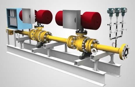
4 Final Elements A HIPPS loop is composed of: - initiators, that detect the high pressure - logic solver, which processes the input from the sensors to an output to the final element - final elements, that actually perform the corrective action in the field by bringing the process to a safe state. In case of a HIPPS this means shutting off the source of overpressure. The final element consists of a valve, actuator and solenoids.
5 Final Elements Final element selection should be done taking into account: - The particular application - The process and design conditions - The suitability for use in safety applications - The frequency of site testing - The desired HIPPS lifetime before re-certification
6 Final Elements HIPPS final element assembly should be considered as a whole sub-system. -valve - actuator - SOV s?... - pedestal?... - brackets?... This should be taken into account in the design, the fabrication and the testing. Complete FAT required. The relevant documentation should be managed by the same principle.
7 MOKVELD HIPPS 3,65x10⁻⁴ Fault tree analyses HIPPS CCF: SOL s 1,0x10⁻⁴ CCF: FE s 2,3x10⁻⁴ PROSAFE Controller (AK7) 5x10⁻⁷ CCF: PT s 2,7x10⁻⁵ 1oo2 for combination of 2 sequential FE s 5,5x10⁻⁶ 2oo3 for 2oo3 Voting PT 2,2x st FE 2,3x nd FE 2,3x st FE 2 nd FE PT1 & PT2 PT1 & PT3 PT2 & PT3 Final Element 2,3x10⁻³ Final Element 2,3x10⁻³ 2,7x10⁻⁴ 2,7x10⁻⁴ 2,7x10⁻⁴ 2,7x10⁻⁴ 2,7x10⁻⁴ 2,7x10⁻⁴ 1oo2 1,0x10⁻⁶ 1oo2 1,0x10⁻⁶ PT1 PT2 PT1 PT3 PT2 PT3 Solenoid 1,0x10⁻³ Solenoid 1,0x10⁻³ Solenoid 1,0x10⁻³ Solenoid 1,0x10⁻³ PT1 1,3x10⁻⁴ TF2 1,3x10⁻⁴ Input card 1 1,4x10⁻⁴ Input card 2 1,4x10⁻⁴ PT1 1,3x10⁻⁴ PT3 1,3x10⁻⁴ Input card 1 1,4x10⁻⁴ Input card 3 1,4x10⁻⁴ PT2 1,3x10⁻⁴ PT3 1,3x10⁻⁴ Input card 2 1,4x10⁻⁴ Input card 3 1,4x10⁻⁴
8 Final Elements Final elements account for 50% of safety loop failures historically and their contribution to (avg) is higher than that the one of sensors and logic solver. In short, performance of HIPPS is highly dependent on the quality of the FEs.

9 Final Elements
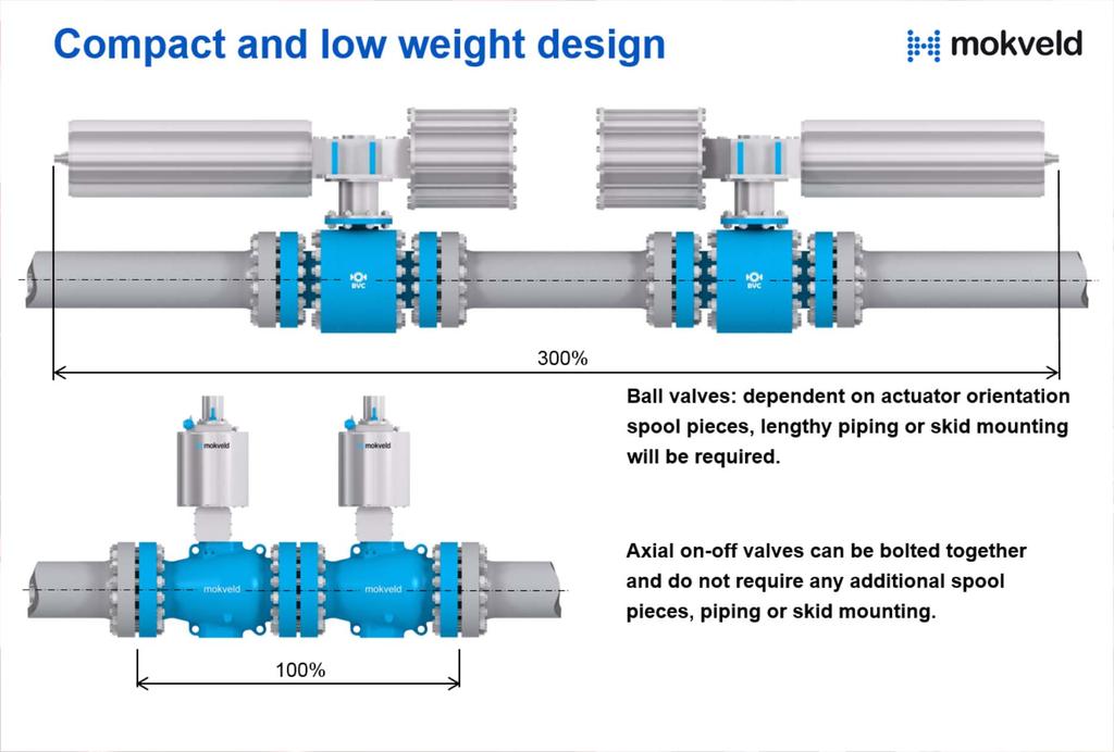
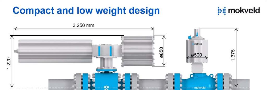
10 HIPPS Final element; Desired Features and Benefits 1. No equalising by-pass required 2. Low pressure drop 3. Fast closure 4. Excellent sealing 5. Compact and low weight 6. Fire safe 7. Infrequent use w/o partial stroking 8. Failure data from field experience
11 Bypass Lines Where a HIPPS bypass is required (e.g. for pressure equalization post HIPPS activation), this should not compromise the HIPPS integrity. The bypass should be locked closed or similar (e.g. interlocked) to prevent being left in the open position. Leak tightness and SIL specification for the bypass should be equivalent to that of the main HIPPS valves.
12 Fast Closing The process safety time, HIPPS reaction time and HIPPS response time should be defined in the HIPPS SRS HIPPS reaction time ThemaximumallowabletimeinwhichtheHIPPSshould prevent a hazardous operational condition. It is thus the time between the process threshold value occurring and the occurrence of the hazardous event. HIPPS response time The time between the process threshold value occurring until the final element has reached its safe state.

13 Fast Closing A «fast» closing valve may still not meet the process safety time! All elements have to be considered.

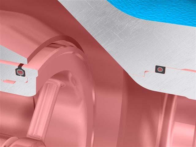
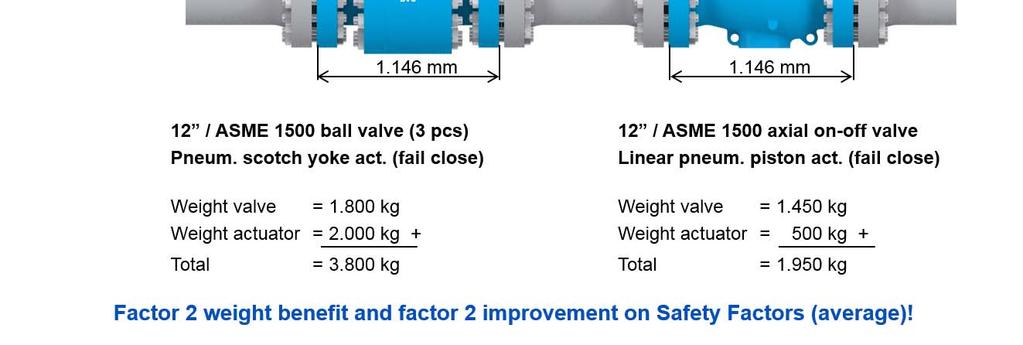
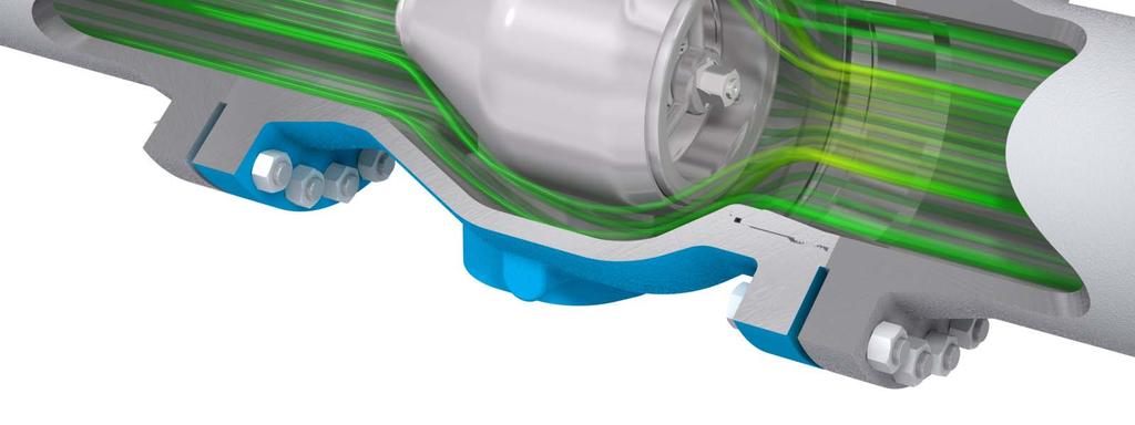
14 Fast Closing with Full Pressure Balancing
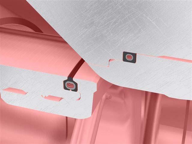

15 Sealing: Bi-directional Tight Shut-Off, even on unclean duty
16 Leakage rates Although valves may be specified as zeroleakage (e.g. ISO 5208 or API Standard 598), in reality it should be assumed that some leakage in service will always occur. As such, the downstream process system should be able to handle a degree of leakage. The leakage rate should be determined in conjunction with Process design Engineers and will typically be based upon the greatest of: 100% Flow through a valve bypass (if installed) when open that experienced following total collapse of soft seats (where fitted) a percentage of design flow (assessed in discussion with valve manufacturer) for metal seated valves.
17
18

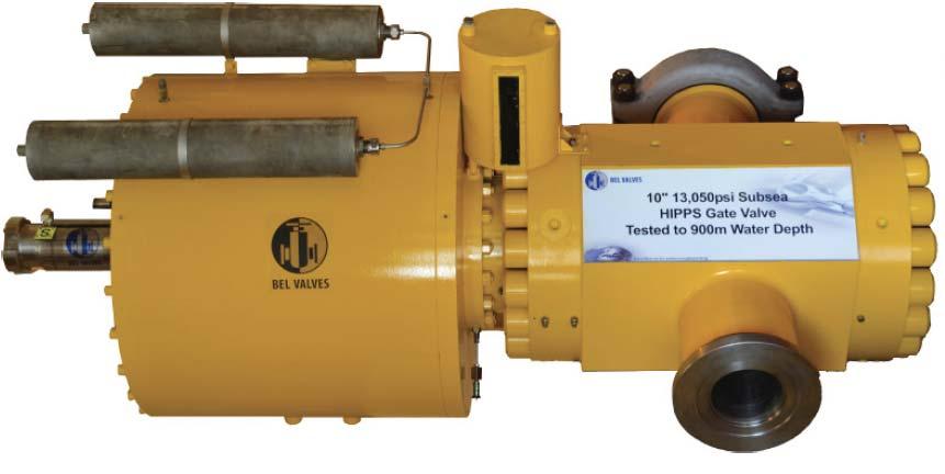
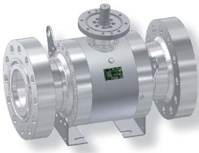
19 HIPPS actuators Linear piston or quarter turn actuator integrated dampening pneumatic or hydraulic multiple parallel springs closed pedestal rugged design
20 Final Elements/ actuators The IEC does not give the final elements the attention they deserve, the IEC already has more focus on this part of the loop. This is specifically required for fast acting safety loops (requiring shut-off within 2 seconds) in a low demand mode. The EN recognizes this and refers to the EN for the design of the final element
21 Final Elements/ actuators The European standard EN (DIN G491) and more specific the EN (DIN 3381) has been used for many years in (mechanically) instrumented overpressure protection systems. These standards prescribe the requirements for the overpressure protection systems, and their components, in gas plants. Not only the response time and accuracy of the loop but also safety factors for over-sizing of the actuator of the final element are dictated by these standards. Independent design verification and testing to prove compliance to the EN standard is suggested..
 stem packing adjustment; (2) spring tension on the seats; (3)")
 trunnion bearing friction; (5) dp across the valve.")
22 Torque considerations Torque on a trunnion ball valve is a function of: (1) stem packing adjustment; (2) spring tension on the seats; (3) coefficient of sliding friction between the ball and the seating material; (4) trunnion bearing friction; (5) dp across the valve. 2,0x safety factor suggested.
23 Torque considerations Workshop tests should simulate or otherwise be representative of: actual service in which the valve will be employed, i.e. gas service or liquid service maximum design differential pressures across the valve actual valve configurations i.e. seat type, stem extensions, etc. closure within specified time (speed of closure affects torque required).

24 Fail Safe function The valve fail-safe function should be achieved by spring return actuators. Other solutions such as operating pressure inside the valve or double acting piston actuators should only be considered if there are justifiable reasons not to use the spring return option.
25 Required redundancy acc. IEC route 2 s Safety Integrity Level Architecture for final elements and sensors proven in use Comments SIL HWFT Redundancy For type A and B where for type B DC shall be > 60% 1 0 1oo1 All cases 2 1 1oo2 High or Continuous mode 2 0 1oo1 Low demand mode <1 per year 3 1 1oo2 All cases 4 2 but should be avoided
26 Required redundancy according IEC Safety Integrity Level Architecture for final elements and sensors Architecture when proven in use SIL HWFT Redundancy HWFT Redundancy 1 0 1oo1 0 1oo oo2 0 1oo oo3 1 1oo2 4 Special requirements to IEC 61508
27 MOKVELD HIPPS 3,65x10⁻⁴ Common Cause Failures CCF: SOL s 1,0x10⁻⁴ CCF: FE s 2,3x10⁻⁴ PROSAFE Controller (AK7) 5x10⁻⁷ CCF: PT s 2,7x10⁻⁵ 1oo2 for combination of 2 sequential FE s 5,5x10⁻⁶ 2oo3 for 2oo3 Voting PT 2,2x st FE 2,3x nd FE 2,3x st FE 2 nd FE PT1 & PT2 PT1 & PT3 PT2 & PT3 Final Element 2,3x10⁻³ Final Element 2,3x10⁻³ 2,7x10⁻⁴ 2,7x10⁻⁴ 2,7x10⁻⁴ 2,7x10⁻⁴ 2,7x10⁻⁴ 2,7x10⁻⁴ 1oo2 1,0x10⁻⁶ 1oo2 1,0x10⁻⁶ PT1 PT2 PT1 PT3 PT2 PT3 Solenoid 1,0x10⁻³ Solenoid 1,0x10⁻³ Solenoid 1,0x10⁻³ Solenoid 1,0x10⁻³ PT1 1,3x10⁻⁴ TF2 1,3x10⁻⁴ Input card 1 1,4x10⁻⁴ Input card 2 1,4x10⁻⁴ PT1 1,3x10⁻⁴ PT3 1,3x10⁻⁴ Input card 1 1,4x10⁻⁴ Input card 3 1,4x10⁻⁴ PT2 1,3x10⁻⁴ PT3 1,3x10⁻⁴ Input card 2 1,4x10⁻⁴ Input card 3 1,4x10⁻⁴
28 Common Cause Failures modeled with β - factor CCF influenced by: - equipment selection - maintenance / commissioning - environment (external, internal / corrosion) - Physical separation IEC 61508: lower than 1% difficult to obtain IEC 61511: examples / typical 10% Identical equipment, same personnel min. 5%
29 Common Cause Failures 1) Within HIPPS: the use of identical sensors/final elements in a voting (e.g. 1oo2/2oo3) configuration has the advantage of simplifying procurement and maintenance activities, but will increase the potential for CMF
30 Common Cause Failures For SIL 3 (and below) HIPPS, it is usually acceptable to utilize identical sensing/final element devices, but for higher integrity service diverse (i.e. make/model) sensing and final element devices should be deployed. At SIL 3, the potential benefits of diverse sensing and final element devices versus the potential detriment to system maintenance should be considered.
31 Common Cause Failures 2) Within other protection layers: if identical make and model of sensing and/ or final element is utilized for both the HIPPS and other protection layers, the potential for CMF between the HIPPS and other protection layers should be addressed.


32 Axial Flow A Unique and Mature Design now

33 Axial On-Off Valve Axial Excellence
34 We thank you for your attention
High Integrity Pressure Protection Systems HIPPS
 High Integrity Pressure Protection Systems HIPPS HIPPS > High Integrity Pressure Protection Systems WHAT IS A HIPPS The High Integrity Pressure Protection Systems (HIPPS) is a mechanical and electrical
L&T Valves Limited SAFETY INTEGRITY LEVEL (SIL) VERIFICATION FOR HIGH INTEGRITY PRESSURE PROTECTION SYSTEM (HIPPS) Report No.
 VERIFICATION FOR HIGH INTEGRITY PRESSURE PROTECTION SYSTEM (HIPPS) Report No.") L&T Valves Limited TAMIL NADU SAFETY INTEGRITY LEVEL (SIL) VERIFICATION FOR HIGH INTEGRITY PRESSURE PROTECTION SYSTEM (HIPPS) MAY 2016 Report No. 8113245702-100-01 Submitted to L&T Valves Ltd. Report by
L&T Valves Limited TAMIL NADU SAFETY INTEGRITY LEVEL (SIL) VERIFICATION FOR HIGH INTEGRITY PRESSURE PROTECTION SYSTEM (HIPPS) MAY 2016 Report No. 8113245702-100-01 Submitted to L&T Valves Ltd. Report by
DeZURIK. KGC Cast Knife Gate Valve. Safety Manual
 KGC Cast Knife Gate Valve Safety Manual Manual D11036 August 29, 2014 Table of Contents 1 Introduction... 3 1.1 Terms... 3 1.2 Abbreviations... 4 1.3 Product Support... 4 1.4 Related Literature... 4 1.5
Every things under control High-Integrity Pressure Protection System (HIPPS)
") Every things under control www.adico.co info@adico.co Table Of Contents 1. Introduction... 2 2. Standards... 3 3. HIPPS vs Emergency Shut Down... 4 4. Safety Requirement Specification... 4 5. Device Integrity
Every things under control www.adico.co info@adico.co Table Of Contents 1. Introduction... 2 2. Standards... 3 3. HIPPS vs Emergency Shut Down... 4 4. Safety Requirement Specification... 4 5. Device Integrity
TRI LOK SAFETY MANUAL TRI LOK TRIPLE OFFSET BUTTERFLY VALVE. The High Performance Company
 TRI LOK TRI LOK TRIPLE OFFSET BUTTERFLY VALVE SAFETY MANUAL The High Performance Company Table of Contents 1.0 Introduction...1 1.1 Terms and Abbreviations... 1 1.2 Acronyms... 1 1.3 Product Support...
Implementing IEC Standards for Safety Instrumented Systems
 Implementing IEC Standards for Safety Instrumented Systems ABHAY THODGE TUV Certificate: PFSE-06-607 INVENSYS OPERATIONS MANAGEMENT What is a Safety Instrumented System (SIS)? An SIS is designed to: respond
Eutectic Plug Valve. SIL Safety Manual. SIL SM.015 Rev 0. Compiled By : G. Elliott, Date: 19/10/2016. Innovative and Reliable Valve & Pump Solutions
 SIL SM.015 Rev 0 Eutectic Plug Valve Compiled By : G. Elliott, Date: 19/10/2016 Contents Terminology Definitions......3 Acronyms & Abbreviations...4 1. Introduction..5 1.1 Scope 5 1.2 Relevant Standards
Solenoid Valves used in Safety Instrumented Systems
 I&M V9629R1 Solenoid Valves used in Safety Instrumented Systems Operating Manual in accordance with IEC 61508 ASCO Valves Page 1 of 7 Table of Contents 1 Introduction...3 1.1 Terms and Abbreviations...3
RESILIENT SEATED BUTTERFLY VALVES FUNCTIONAL SAFETY MANUAL
 Per IEC 61508 and IEC 61511 Standards BRAY.COM Table of Contents 1.0 Introduction.................................................... 1 1.1 Terms and Abbreviations...........................................
Neles trunnion mounted ball valve Series D Rev. 2. Safety Manual
 Neles trunnion mounted ball valve Series D Rev. 2 Safety Manual 10SM D en 1/2017 2 Neles trunnion mounted ball valve, Series D Table of Contents 1 Introduction...3 2 Structure of the D series trunnion
This manual provides necessary requirements for meeting the IEC or IEC functional safety standards.
 Instruction Manual Supplement Safety manual for Fisher Vee-Ball Series Purpose This safety manual provides information necessary to design, install, verify and maintain a Safety Instrumented Function (SIF)
Partial Stroke Testing. A.F.M. Prins
 Partial Stroke Testing A.F.M. Prins Partial Stroke Testing PST in a safety related system. As a supplier we have a responsibility to our clients. What do they want, and what do they really need? I like
DeZURIK. KSV Knife Gate Valve. Safety Manual
 KSV Knife Gate Valve Safety Manual Manual D11035 August 29, 2014 Table of Contents 1 Introduction... 3 1.1 Terms... 3 1.2 Abbreviations... 4 1.3 Product Support... 4 1.4 Related Literature... 4 1.5 Reference
Valve Communication Solutions. Safety instrumented systems
 Safety instrumented systems Safety Instrumented System (SIS) is implemented as part of a risk reduction strategy. The primary focus is to prevent catastrophic accidents resulting from abnormal operation.
Safety manual for Fisher GX Control Valve and Actuator
 Instruction Manual Supplement GX Valve and Actuator Safety manual for Fisher GX Control Valve and Actuator Purpose This safety manual provides information necessary to design, install, verify and maintain
DeZURIK Double Block & Bleed (DBB) Knife Gate Valve Safety Manual
 Knife Gate Valve Safety Manual") Double Block & Bleed (DBB) Knife Gate Valve Safety Manual Manual D11044 September, 2015 Table of Contents 1 Introduction... 3 1.1 Terms... 3 1.2 Abbreviations... 4 1.3 Product Support... 4 1.4 Related
Double Block & Bleed (DBB) Knife Gate Valve Safety Manual Manual D11044 September, 2015 Table of Contents 1 Introduction... 3 1.1 Terms... 3 1.2 Abbreviations... 4 1.3 Product Support... 4 1.4 Related
Hydraulic (Subsea) Shuttle Valves
 Shuttle Valves") SIL SM.009 0 Hydraulic (Subsea) Shuttle Valves Compiled By : G. Elliott, Date: 11/3/2014 Contents Terminology Definitions......3 Acronyms & Abbreviations..4 1. Introduction 5 1.1 Scope 5 1.2 Relevant Standards
SIL SM.009 0 Hydraulic (Subsea) Shuttle Valves Compiled By : G. Elliott, Date: 11/3/2014 Contents Terminology Definitions......3 Acronyms & Abbreviations..4 1. Introduction 5 1.1 Scope 5 1.2 Relevant Standards
Neles ValvGuard VG9000H Rev 2.0. Safety Manual
 Neles ValvGuard VG9000H Rev 2.0 Safety Manual 10SM VG9000H en 11/2016 2 Neles ValvGuard VG9000H Rev 2.0 Safety Manual Table of Contents 1 General information...3 1.1 Purpose of the document... 3 1.2 Description
EL-O-Matic E and P Series Pneumatic Actuator SIL Safety Manual
 SIL Safety Manual DOC.SILM.EEP.EN Rev. 0 April 2017 EL-O-Matic E and P Series Pneumatic Actuator SIL Safety Manual schaal 1:1 EL Matic TM EL-O-Matic E and P Series DOC.SILM.EEP.EN Rev. 0 Table of Contents
SIL explained. Understanding the use of valve actuators in SIL rated safety instrumented systems ACTUATION
 SIL explained Understanding the use of valve actuators in SIL rated safety instrumented systems The requirement for Safety Integrity Level (SIL) equipment can be complicated and confusing. In this document,
Jamesbury Pneumatic Rack and Pinion Actuator
 Jamesbury Pneumatic Rack and Pinion Actuator Valv-Powr Series VPVL Rev. 3.0 Safety Manual 10SM VPVL en 5/2017 2 Jamesbury Pneumatic Rack and Pinion Actuator, Valv-Powr Series VPVL, Rev 3.0, Safety Manual
SIL Safety Manual. ULTRAMAT 6 Gas Analyzer for the Determination of IR-Absorbing Gases. Supplement to instruction manual ULTRAMAT 6 and OXYMAT 6
 ULTRAMAT 6 Gas Analyzer for the Determination of IR-Absorbing Gases SIL Safety Manual Supplement to instruction manual ULTRAMAT 6 and OXYMAT 6 ULTRAMAT 6F 7MB2111, 7MB2117, 7MB2112, 7MB2118 ULTRAMAT 6E
High performance disc valves Series Type BA, BK, BW, BM, BN, BO, BE, BH Rev Safety Manual
 High performance disc valves Series Type BA, BK, BW, BM, BN, BO, BE, BH Rev. 2.0 Safety Manual 10SM B Disc en 4/2018 2 High performance disc valves Series, Type BA, BK, BW, BM, BN, BO, BE, BH, Rev. 2.0
SIL Safety Manual for Fisherr ED, ES, ET, EZ, HP, or HPA Valves with 657 / 667 Actuator
 SIL Safety Manual ED, ES, ET, EZ, HP, HPA Valves w/ 657/667 Actuator SIL Safety Manual for Fisherr ED, ES, ET, EZ, HP, or HPA Valves with 657 / 667 Actuator Purpose This safety manual provides information
Ultima. X Series Gas Monitor
 Ultima X Series Gas Monitor Safety Manual SIL 2 Certified " The Ultima X Series Gas Monitor is qualified as an SIL 2 device under IEC 61508 and must be installed, used, and maintained in accordance with
Bespoke Hydraulic Manifold Assembly
 SIL SM.0003 1 Bespoke Hydraulic Manifold Assembly Compiled By : G. Elliott, Date: 12/17/2015 Contents Terminology Definitions......3 Acronyms & Abbreviations..4 1. Introduction 5 1.1 Scope 5 1.2 Relevant
FP15 Interface Valve. SIL Safety Manual. SIL SM.018 Rev 1. Compiled By : G. Elliott, Date: 30/10/2017. Innovative and Reliable Valve & Pump Solutions
 SIL SM.018 Rev 1 FP15 Interface Valve Compiled By : G. Elliott, Date: 30/10/2017 FP15/L1 FP15/H1 Contents Terminology Definitions......3 Acronyms & Abbreviations...4 1. Introduction...5 1.1 Scope.. 5 1.2
Pneumatic QEV. SIL Safety Manual SIL SM Compiled By : G. Elliott, Date: 8/19/2015. Innovative and Reliable Valve & Pump Solutions
 SIL SM.0010 1 Pneumatic QEV Compiled By : G. Elliott, Date: 8/19/2015 Contents Terminology Definitions......3 Acronyms & Abbreviations..4 1. Introduction 5 1.1 Scope 5 1.2 Relevant Standards 5 1.3 Other
Failure Modes, Effects and Diagnostic Analysis
 Failure Modes, Effects and Diagnostic Analysis Project: Abc. X Series Ball Valve Company: Abc. Inc. Sellersville, PA USA Contract Number: Q11/12-345 Report No.: Abc 11/12-345 R001 Version V1, Revision
PREDICTING HEALTH OF FINAL CONTROL ELEMENT OF SAFETY INSTRUMENTED SYSTEM BY DIGITAL VALVE CONTROLLER
 PREDICTING HEALTH OF FINAL CONTROL ELEMENT OF SAFETY INSTRUMENTED SYSTEM BY DIGITAL VALVE CONTROLLER Riyaz Ali FIELDVUE Business Development Manager Fisher Controls Int'l., LLC. Marshalltown, IA 50158
HIPPS Development Project
 Hydraulic HIPPS HIPPS Development Project This presentation describes the Energy Equipment Corporation Hydraulic HIPPS control development project, and gives: Brief background information about Energy
PL estimation acc. to EN ISO
 PL estimation acc. to EN ISO 3849- Example calculation for an application MAC Safety / Armin Wenigenrath, January 2007 Select the suitable standard for your application Reminder: The standards and the
THE NATURAL CHOICE. High end valves for the natural gas value chain. Inspired By Challenge
 THE NATURAL CHOICE High end valves for the natural gas value chain Inspired By Challenge 01 NATURAL GAS SOURCES For drilling platforms, FPSO (Floating, Production, Storage and Offloading) and FSRUs (Floating
YT-3300 / 3301 / 3302 / 3303 / 3350 / 3400 /
 Smart positioner YT-3300 / 3301 / 3302 / 3303 / 3350 / 3400 / 3410 / 3450 Series SIL Safety Instruction. Supplement to product manual July. 2015 YTC Ver 1.06 1 Table of contents 1 Introduction... 3 1.1
Solenoid Valves For Gas Service FP02G & FP05G
 SIL Safety Manual SM.0002 Rev 02 Solenoid Valves For Gas Service FP02G & FP05G Compiled By : G. Elliott, Date: 31/10/2017 Reviewed By : Peter Kyrycz Date: 31/10/2017 Contents Terminology Definitions......3
Safety Manual OPTISWITCH series relay (DPDT)
") Safety Manual OPTISWITCH series 5000 - relay (DPDT) 1 Content Content 1 Functional safety 1.1 In general................................ 3 1.2 Planning................................. 5 1.3 Adjustment
Safety Manual OPTISWITCH series 5000 - relay (DPDT) 1 Content Content 1 Functional safety 1.1 In general................................ 3 1.2 Planning................................. 5 1.3 Adjustment
YT-300 / 305 / 310 / 315 / 320 / 325 Series
 Volume Booster YT-300 / 305 / 310 / 315 / 320 / 325 Series SIL Safety Instruction. Supplement to product manual Apr. 2016 YTC Ver. 2.01 1 Table of contents 1 Introduction... 3 1.1 Purpose of this document...
Control Valve : The Final Control Element. Nimish Shah
 Control Valve : The Final Control Element Nimish Shah VALVES How to select Control Valve??? selection parameters for the valve : size, material of construction, pressure and temperature ratings, and End
Safety Manual. Process pressure transmitter IPT-1* 4 20 ma/hart. Process pressure transmitter IPT-1*
 Safety Manual Process pressure transmitter IPT-1* 4 20 ma/hart Process pressure transmitter IPT-1* Contents Contents 1 Functional safety 1.1 General information... 3 1.2 Planning... 4 1.3 Instrument parameter
Special Documentation Proline Promass 80, 83
 SD00077D/06/EN/14.14 71272498 Products Solutions Services Special Documentation Proline Promass 80, 83 Functional safety manual Coriolis mass flow measuring system with 4 20 ma output signal Application
SPR - Pneumatic Spool Valve
 SIL SM.008 Rev 7 SPR - Pneumatic Spool Valve Compiled By : G. Elliott, Date: 31/08/17 Contents Terminology Definitions:... 3 Acronyms & Abbreviations:... 4 1.0 Introduction... 5 1.1 Purpose & Scope...
Reliability of Safety-Critical Systems Chapter 4. Testing and Maintenance
 Reliability of Safety-Critical Systems Chapter 4. Testing and Maintenance Mary Ann Lundteigen and Marvin Rausand mary.a.lundteigen@ntnu.no RAMS Group Department of Production and Quality Engineering NTNU
A Complete Solution For HIPPS
 A Complete Solution For HIPPS Are You Also Facing These Challenges For Your HIPPS? PERFORMANCE Test and Working procedures / Safety Life Cycle ENVIRONMENT Fugitive Emissions / Reduce or Eliminate Flares
Deltaflux Control Valve
 Control Valve Valvola di regolazione control valve is an ideal solution for all fluid control applications where high differential pressure or great flow rates are involved. The refined design of the rotating
Valve Inspection & Testing
 Inspection & Testing in accordance with API 598 Valve Inspection & Testing Shell Test (Body Hydro Test): - Each valve shall be tested in accordance with ASME B 16.34 for ASME valves. Shell test pressure
Partial Stroke Testing for SRD991 and SRD960
 Technical Information 09.11 TI EVE0105 PST-(en) Partial Stroke Testing for SRD991 and SRD960 Final control elements in Emergency Shutdown (ESD) applications such as ON-OFF-, Blow Down and Venting-Valves
Session One: A Practical Approach to Managing Safety Critical Equipment and Systems in Process Plants
 Session One: A Practical Approach to Managing Safety Critical Equipment and Systems in Process Plants Tahir Rafique Lead Electrical and Instruments Engineer: Qenos Botany Site Douglas Lloyd Senior Electrical
FALL 2002 VOLUME 14, NO. 4. Advances in Valve & Actuator Technologies FALL
 FALL 2002 VOLUME 14, NO. 4 M A G A Z I N E Advances in Valve & Actuator Technologies FALL 2002 1 CONSIDER Mechanical Partial FOR PROCESS ESD by Mike Mitchell There is a storm forming on the horizon for
Safety in pneumatic automation
 Safety in pneumatic automation Pharm connect congress 2014 Budapest Feb. 26. 27. Thomas Schulz Head of ISM and KAM Biotech/Pharma Phone: +49-711/347-52192 Mail: thss@de.festo.com Thomas Schulz / CP-KB
Safety Integrity Verification and Validation of a High Integrity Pressure Protection System (HIPPS) to IEC 61511
 to IEC 61511") Safety Integrity Verification and Validation of a High Integrity Pressure Protection System (HIPPS) to IEC 61511 Abstract Author: Colin Easton ProSalus Limited ~ Independent Safety Consultants A key requirement
Safety Integrity Verification and Validation of a High Integrity Pressure Protection System (HIPPS) to IEC 61511 Abstract Author: Colin Easton ProSalus Limited ~ Independent Safety Consultants A key requirement
T e l N o : F a x N o : E m a i l : a i s h c m c - m e. c o m w w w. c m c - m e.
 MU047: Practical Valve Technology: Selection, Installation, Upgrading, Inspection & Troubleshooting MU047 Rev.002 CMCT COURSE OUTLINE Page 1 of 7 Training Description: This five-day intensive course covers
Ball valve HKSF-W100. Ball valve HKSF-W100. RMA Kehl GmbH & Co. KG Oststrasse 17 D Kehl / Germany
 Ball valve HKSF-W100 RMA Kehl GmbH & Co. KG Oststrasse 17 D-77694 Kehl / Germany info@rma-kehl.de www.rma-armaturen.de 1 Design Features: RMA-ball valves type HKSF-W are fully welded and completely maintenance-free
Safety Manual VEGAVIB series 60
 Safety Manual VEGAVIB series 60 Contactless electronic switch Document ID: 32002 Contents Contents 1 Functional safety... 3 1.1 General information... 3 1.2 Planning... 4 1.3 Adjustment instructions...
Safety Manual VEGAVIB series 60
 Safety Manual VEGAVIB series 60 NAMUR Document ID: 32005 Contents Contents 1 Functional safety... 3 1.1 General information... 3 1.2 Planning... 4 1.3 Adjustment instructions... 6 1.4 Setup... 6 1.5 Reaction
Leak testing of Valves. Standards for acceptable Rates of Valve Leakage
 Leak testing of Valves Standards for acceptable Rates of Valve Leakage American Petroleum Institute (API) The API standard 598: Valve Inspection and Testing, covers the testing and inspection requirements
EMERGENCY SHUT-DOWN RELIABILITY ADVANTAGE
 Your partner in Fluid Control Solutions EMERGENCY SHUT-DOWN RELIABILITY ADVANTAGE George Cao 06 May, 2011 1. ESD Overview Why Do You Need ESD Solution? Safety! Safety!! Safety!!! Safety Is a Must! The
Mounting and Operating Instructions EB 3007 EN. Self-operated Pressure Regulators. Differential Pressure Regulators (opening) Type Type 42-25
 Type Type 42-25") Self-operated Pressure Regulators Differential Pressure Regulators (opening) Type 42-20 Type 42-25 Type 42-20 Differential Pressure Regulator Type 42-25 Differential Pressure Regulator Mounting and Operating
Self-operated Pressure Regulators Differential Pressure Regulators (opening) Type 42-20 Type 42-25 Type 42-20 Differential Pressure Regulator Type 42-25 Differential Pressure Regulator Mounting and Operating
Paul Ladage 26 September 2017 MOVING THINGS AROUND - LATEST TRENDS IN HONEYWELL FLAGSHIP REGULATORS
 Paul Ladage 26 September 2017 MOVING THINGS AROUND - LATEST TRENDS IN HONEYWELL FLAGSHIP REGULATORS Agenda 1 What do we sell? Flagship Products HON 5020 HON R100 NG HON 512, class 150 Q&A Where Do Honeywell
The benefits of the extended diagnostics feature. Compact, well-proven, and flexible
 ABB MEASUREMENT & ANALYTICS TECHNICAL INFORMATION PositionMaster EDP300 Extended Diagnostics Compact, well-proven, and flexible The benefits of the extended diagnostics feature The PositionMaster EDP300
PositionMaster EDP300 Extended Diagnostics. Compact, well-proven, and flexible
 Change from one to two columns Technical Information TI/EDP300_ED-EN Rev. A PositionMaster EDP300 Extended Diagnostics Compact, well-proven, and flexible The benefits of the extended diagnostics feature
Pressure independent control valve (PICV) FLOWMATIC
 FLOWMATIC") Pressure independent control valve (PICV) FLOWMATIC 145 series FM 21654 003 01262/19 GB replaces dp 01262/17 GB Function The pressure independent control valve is a device composed of an automatic flow
Pressure independent control valve (PICV) FLOWMATIC 145 series FM 21654 003 01262/19 GB replaces dp 01262/17 GB Function The pressure independent control valve is a device composed of an automatic flow
CONTROL VALVE SEAT LEAKAGE
 ANSIIFCI 70-2-2006 AMERICAN NATIONAL STANDARD CONTROL VALVE SEAT LEAKAGE \D o N I N I o ~ H U ~ H [/) ~ Fluid Controls Institute, Inc. Spo~sor: Fluid Controls institute, inc. 1300 Sumner Ave Cleveland,
Knowledge, Certification, Networking
 www.iacpe.com Knowledge, Certification, Networking Page :1 of 71 Rev 01 Sept 2016 IACPE No 19, Jalan Bilal Mahmood 80100 Johor Bahru Malaysia The International of is providing the introduction to the Training
Industrial Valves and Automation
 Industrial Valves and Automation Prodim is the preferred supplier of over 20 leading European valve brands Our customers rely on Prodim for quality products, on-time delivery and product know-how 2 prodim.biz
model for functional safety of
 Application of Weibull reliability model for functional safety of electro-hydraulic system 1 When the safety of the machinery users relies on a reliable function of the control system, than a safety function
STANDARD FOR CONTROL VALVE SEAT LEAKAGE
 11-3 STANDARD FOR CONTROL VALVE SEAT LEAKAGE 1. PURPOSE 1.1 This standard establishes a series of seat leakage classes for control valves and defines the test procedures. 2. SCOPE & LIMITATIONS 2.1 Selection
CONTROL VALVE TESTING
 The optimal functioning of the Control valve not only exists of sufficient body & seat tightness, but more important, the total "performance" of the valve and its controls! For an accurate and reliable
API th Edition Ballot Item 6.8 Work Item 54 Global Air Failure
 API 521 7 th Edition Ballot Item 6.8 Work Item 54 Global Air Failure Background Work Item 54: # Source Section Comment Proposed Change Volunteer 54 Fall 2014 meeting Global instrument air failure scenario
New Thinking in Control Reliability
 Doug Nix, A.Sc.T. Compliance InSight Consulting Inc. New Thinking in Control Reliability Or Your Next Big Headache www.machinerysafety101.com (519) 729-5704 Control Reliability Burning Questions from the
Reliability of Safety-Critical Systems Chapter 3. Failures and Failure Analysis
 Reliability of Safety-Critical Systems Chapter 3. Failures and Failure Analysis Mary Ann Lundteigen and Marvin Rausand mary.a.lundteigen@ntnu.no RAMS Group Department of Production and Quality Engineering
ACTUATORS AND INSTRUMENTS
 ACTUATORS AND 03 ADVANCED ACTUATORS AND FOR A COMPLETE VALVE CONTROL SOLUTION Koso Kent Introl LIMITED (KKI) supplies a full range of advanced actuators and associated instrumentation to complement its
Section 1: Multiple Choice
 CFSP Process Applications Section 1: Multiple Choice EXAMPLE Candidate Exam Number (No Name): Please write down your name in the above provided space. Only one answer is correct. Please circle only the
2/2-Way Solenoid Control Valve
 2/2-Way Solenoid Control Valve Excellent range (1:200) Very good response Compact valve design Orifice sizes 0.05... 2.0 mm Port connection 1/8 or sub-base Type 2871 can be combined with Type 8605 Digital
Proof Testing A key performance indicator for designers and end users of Safety Instrumented Systems
 Proof Testing A key performance indicator for designers and end users of Safety Instrumented Systems EUR ING David Green BEng(hons) CEng MIET MInstMC RFSE Ron Bell OBE BSc CEng FIET Engineering Safety
CHE Well Testing Package/Service:
 CHE Well Testing Package/Service: CHE delivers well testing package And services, trailer mounted well testing package and offshore/onshore well testing services with over 10 years experience. Our testing
Functional safety. Functional safety of Programmable systems, devices & components: Requirements from global & national standards
 Functional safety Functional safety of Programmable systems, devices & components: Requirements from global & national standards Matthias R. Heinze Vice President Engineering TUV Rheinland of N.A. Email
Safety Manual VEGASWING 61, 63. NAMUR With SIL qualification. Document ID: 52084
 Safety Manual VEGASWING 61, 63 NAMUR With SIL qualification Document ID: 52084 Contents Contents 1 Document language 2 Scope 2.1 Instrument version... 4 2.2 Area of application... 4 2.3 SIL conformity...
Understanding safety life cycles
 Understanding safety life cycles IEC/EN 61508 is the basis for the specification, design, and operation of safety instrumented systems (SIS) Fast Forward: IEC/EN 61508 standards need to be implemented
FUEL GAS FIRING CONTROL RJ (Dick) Perry Safety Systems Consultant 6 June 2016
 Perry Safety Systems Consultant 6 June 2016") INTRODUCTION Fired equipment such as Heaters and Boilers, normally have to comply with either NFPA 85/86 or API 556 for North America and some other countries which apply such standards, or EN 746-2 for
INTRODUCTION Fired equipment such as Heaters and Boilers, normally have to comply with either NFPA 85/86 or API 556 for North America and some other countries which apply such standards, or EN 746-2 for
Design of Relief Valves/Devices/Systems for Cryogenic Apparatuses and Installations
 Design of Relief Valves/Devices/Systems for Cryogenic Apparatuses and Installations Fridolin Holdener fridolin.holdener@shirokuma-gmbh.ch CERN Cryogenic Safety - HSE Seminar 21-22 September 2016 Agenda
Introduction to Machine Safety Standards
 Introduction to Machine Safety Standards Jon Riemer Solution Architect Safety & Security Functional Safety Engineer (TÜV Rheinland) Cyber Security Specialist (TÜV Rheinland) Agenda Understand the big picture
Integrating Safety and Automation
 866-522-2300 / www.asesafety.com Integrating Safety and Automation Presented by: Dennis Aulbrook Safeguarding of Automated Machinery A safeguard is a solution or a combination of solutions that eliminate
Competence in Functional Safety
 MANUAL Competence in Functional Safety Safety-instrumented system Instrumentation Automation SMART IN FLOW CONTROL. SAMSON AIR TORQUE CERA SYSTEM KT-ELEKTRONIK LEUSCH PFEIFFER RINGO SAMSOMATIC STARLINE
Rosemount 2130 Level Switch
 Rosemount 2130 Level Switch Functional Safety Manual Manual Supplement Reference Manual Contents Contents 1Section 1: Introduction 1.1 Scope and purpose of the safety manual.............................................
Interactive Solutions Tool High-Integrity Pressure Protection Systems (HIPPS)
") Interactive olutions Tool High-Integrity s (HIPP) HIPP HIP Types olution ensing Loops Logic olver HIPP Logic olver Intelligent oftware Use this interactive document to: 1. Understand processes and technical
Interactive olutions Tool High-Integrity s (HIPP) HIPP HIP Types olution ensing Loops Logic olver HIPP Logic olver Intelligent oftware Use this interactive document to: 1. Understand processes and technical
Spilt body Flange ball valve. TC-205MFF-PN1640 User Manual English Version. Document No: TC-205MFF-PN1640.Ur-manual. Date: 2007/04/2617. Version: 1.
 Spilt body Flange ball valve TC-205MFF-PN1640 Series PED Category I,II TC-205MFF-PN1640 User Manual English Version Use for company in Europe who will place the product on the market, please amend which
Training Fees 4,000 US$ per participant for Public Training includes Materials/Handouts, tea/coffee breaks, refreshments & Buffet Lunch.
 Training Title CONTROL & SAFETY RELIEF VALVES Training Duration 5 days Training Venue and Dates Control & Safety Relief Valves 5 06-10 May, 2018 $4,000 Dubai, UAE Trainings will be conducted in any of
Tightness controls TC 1 3 and TC 4
 Tightness controls TC 1 3 and TC 4 Test of both safety valves Short test period thanks to logical decision-making in the program sequence Adjustable test period which can be adapted to different systems
CT433 - Machine Safety
 Rockwell Automation On The Move May 16-17 2018 Milwaukee, WI CT433 - Machine Safety Performance Level Selection and Design Realization Jon Riemer Solution Architect Safety & Security Functional Safety
Section 1: Multiple Choice Explained EXAMPLE
 CFSP Process Applications Section 1: Multiple Choice Explained EXAMPLE Candidate Exam Number (No Name): Please write down your name in the above provided space. Only one answer is correct. Please circle
Data Sheet T 8389 EN. Series 3730 and 3731 Types , , , and. EXPERTplus Valve Diagnostic
 Data Sheet T 8389 EN Series 3730 and 3731 Types 3730-2, 3730-3, 3730-4, 3730-5 and Type 3731-3 Electropneumatic Positioners EXPERTplus Valve Diagnostic Application Positioner firmware to detect potential
Operating instruction
 Operating instruction MV, XV, HG, HP, RKO, D2G, TV, BV, WB & SLV 1 Introduction 2 2 Stafsjö s knife gate valves 2 3 Technical information 2 3.1 Pressure test 2 3.2 Labelling 2 4 Storage 3 5 Transportation
Covering RISKS with Interlocked Sensing Elements,
 Covering RISKS with Interlocked Sensing Elements, SIL ensured and other HIPPS Una breve introduzione Dal 1998 distribuiamo su tutto il territorio nazionale strumenti per la misura e controllo dei fluidi,
FULL FLOW GAS BALL VALVES: LONDON EN 331 APPROVED. GAS BALL VALVES
 FULL FLOW GAS BALL VALVES: EN 331 APPROVED. GAS BALL VALVES 066 BALL VALVE, FULL FLOW SIZE PRESSURE CODE PACKING 1/4" (DN 8) 5bar/72,5psi 066B014 12/192 3/8" (DN ) 5bar/72,5psi 066B038 12/192 1/2" (DN
E28/Q28 Safety Exhaust Valve Externally Monitored
 E8/Q8 Safety Exhaust Valve Externally Monitored ulletin 9EM4 the total systems approach to air preparation Features Externally Monitored Safety Exhaust Valve Function When applications demand a safe environment
innova-ve entrepreneurial global 1
 www.utm.my innova-ve entrepreneurial global Safety Integrity Level (SIL) is defined as: Relative level of risk-reduction provided by a safety function to specify a target level of risk reduction. SIL is
PROCESS AUTOMATION SIL. Manual Safety Integrity Level. Edition 2005 IEC 61508/61511
 PROCESS AUTOMATION Manual Safety Integrity Level SIL Edition 2005 IEC 61508/61511 With regard to the supply of products, the current issue of the following document is applicable: The General Terms of
Application Note. Safety Sub-function PUS Category 1, up to PL c. Application Note PUS, Category 1, up to PL c M20 S22 R20 M1 Q20
 Application Note Safety Sub-function PUS Category 1, up to PL c M20 Application Note PUS, Category 1, up to PL c M1 Q20 M2 S22 R20 G2 100227 Title... Application Note PUS, Category 1, up to PL c Version...
FLOW CONTROL BALL VALVES
 FLOW CONTROL BALL VALVES DAFRAM flow control ball valves A complete ball valve range to cover all flow control applications and critical services COMPANY PROFILE DAFRAM S.p.A., founded in 1956, was the
Failure Modes, Effects and Diagnostic Analysis
 Failure Modes, Effects and Diagnostic Analysis Project: 3051S SIS Pressure Transmitter, with Safety Feature Board, Software Revision 3.0 Customer: Rosemount Inc. Chanhassen, MN USA Contract No.: Ros 02/11-07