DM-2 Operation Manual
|
|
|
- Victoria Lambert
- 5 years ago
- Views:
Transcription


1 Retrotec Inc. DM-2 Operation Manual rev Retrotec Inc East Pole Rd. Everson, WA USA Ph
2 Copyright 2011 Retrotec Inc. All rights reserved. This document contains materials protected under International and Federal Copyright Laws. This book contains material protected under International and Federal Copyright Laws and Treaties. Any unauthorized reprint or use of this material is prohibited. No part of this book may be reproduced or transmitted in any form or by any means, electronic or mechanical, including photocopying, recording, or by any information storage and retrieval system without acknowledging Retrotec Inc. as the original source. Retrotec makes no warranties with respect to this documentation and disclaims any implied warranties of merchantability, quality, or fitness for any particular purpose. The information in this document is subject to change without notice. Retrotec reserves the right to make revisions to this publication without obligation to notify any person or entity of any such changes. Infiltrometer, FanTestic, and DucTester are Trademarks of Retrotec Inc. Other trademarks or brand names mentioned herein are trademarks or registered trademarks of their respective owners. Page 2 of 61
3 Table of Contents 1 UNDERSTANDING THE PRESSURE GAUGE...6 Differential Pressure... 6 Positive vs. Negative Pressure... 7 Analog Gauges DM-2 DIGITAL GAUGE BASICS Batteries...9 Install batteries... 9 Rechargeable or non-rechargeable (alkaline) batteries Gauge Overview The Connections Panel The DM-2 Screen The Keypad Resetting the Gauge Screen Contrast DM-2 KEYPAD FUNCTIONS On/Off (Backlight) Exit Enter (Volume/Area) Device Mode Range Config (fan Flow Ranges) Setup Baseline Time Avg Auto Zero Set Pressure Set Speed Jog/Hold... Pressure USING THE DM-2 GAUGE FOR TESTING Making the Connections Pressure port connections Hardware connections Conducting a Basic Test GAUGE SET UP Setup Menu Full Screen Timeout Restore Settings Language Battery Type Display Version Info n Power Down Hour Surface Area Unit Building Volume Unit European, Separator Sig Figs Device Setup Page 3 of 61
4 Enable and Disable Devices Enable and Disable Flow Range Configurations Mode Setup Setting up your DM-2 for a NFPA Enclosure Integrity Test Setting up the units of results for a NFPA Enclosure Integrity test Performing an NFPA 2001 Enclosure Integrity Test (single point test as per 2008 edition) Achieve the Target Pressure (Method 2) Using Set Speed Using the DM-2 to look for the locations of Leaks Setting up for a test with Alaska s AkWarm software FIELD CALIBRATION Gauge Calibration TROUBLESHOOTING DM-2 Rechargeable Battery Problems Serial Number and Calibration Date Check Moving Tubes Cause Fluctuating Pressures Wind causes a fluctuating pressure Time Averaging User Errors Large fixed errors Wrong Flow Range or Device selected No reference tube while pressurizing Windy conditions Pressure overshoots when using the Set Pressure key The keys on the DM-2 Keypad are not working Updating Firmware Firmware Changes APPENDIX A: SYSTEM FLOW EQUATIONS FOR ALL DEVICES APPENDIX B: TEMPERATURE CORRECTION APPENDIX C: EXPONENT ERRORS Page 4 of 61
5 List of Tables Table 1. DM-2 Gauge keys and functions Table 2. Possible results and selectable units for the DM-2 gauge Table 3. Example values displayed using each of the three significant figure options Table 4. List of compatible devices to be used with the DM Table 5. DM-2 compatible devices and associated Flow Range configurations Table 6. Default mode set-up Table 7. Firmware changes from versions prior to 2.29 to the current version Table 8. N and K coefficients for all DM-2 supported fans Table 9. N and K coefficients for all DM-2 supported fans, Obsolete Table 10. Temperature correction factors for enclosure depressurization Table 11. Temperature correction factors for enclosure pressurization Table 12. If the n value on the DM-2 is set to 0.65 and the building n is different, a small error, as shown in the table, will result Table 13. If the n value on the DM-2 is set to 0.60 and the building n is different, a small error, as shown in the table, will result List of Figures Figure 1. Gauge displaying Pa (or 1 in WC) Figure 2. The gauge displays a negative pressure (-1 in WC, or -0.1 Pa) on the DM Figure 3. Digital and analog gauges display a pressure of 50.2 Pa (above); Retrotec s magnahelic gauge system (right) Figure 4 Battery cage and four rechargeable batteries for the DM Figure 5. Splash screen and the main screen with battery life indication in the top left Figure 6. DM-2 back panel with pressure ports and electrical connections Figure 7. Pressure ports of the DM-2 gauge Figure 8. Gauge field check configurations (cross-channel checks (top), cross-gauge checks (bottom)) Figure 10. Syringe check setup Figure 9. Flow pressure check using a T-connection check Figure 11. The effect of a moving tube on pressure readings Figure 12. Errors in pressure reading from a pinched tube Figure 13. Water in the reference tube (left); high fixed pressure due to water (right) Figure 14. Wind-damping kits; basic (left) and deluxe (right) Page 5 of 61

6 1 Understanding the Pressure Gauge A high-performance digital differential pressure gauge offers a number of advantages over analog counterparts: Easy to read Pressure sensors with greater sensitivity Performs calculations that would otherwise need to be done manually A digital gauge, therefore, can save a lot of testing time with proper use of its functions. Note: Before beginning a test, it is absolutely critical to enable and select the proper Device and Range in order to obtain the correct results. Refer to section 3 for instructions on how to enable, select the proper Device, and select the proper Range. Differential Pressure Each gauge consists of two pressure transducers, which each measure the difference in pressure between two Input ports. The most common units of measurement are Pascals (Pa), but inches of water column (in WC) and pounds per square foot (PSF) are also available. Inches of water column is the easiest to visualize because one inch water column (1 in WC) is the amount of pressure required to suck water up a straw to a height of one inch. One inch of water column (in WC) = 249 Pa = 5.2 PSF [pounds per square foot] To measure a pressure 1. Connect a pressure tube to the blue port of the DM Press [On]. 3. Place the end of the tube into a glass of water, slightly more than 1 inch below the surface. The gauge will display around 1.00 in WC, or 250 Pa or 5.2 PSF depending on the units being displayed. (Units can be easily changed using the Setup Menu). Figure 1. Gauge displaying Pa (or 1 in WC). Page 6 of 61
 port than on the negative ( Reference ) port displays a positive pressure on the gauge.")
7 Positive vs. Negative Pressure The DM-2 gauge will display pressures from Pa to Pa. A higher pressure on the positive ( Input ) port than on the negative ( Reference ) port displays a positive pressure on the gauge. Alternatively, a higher pressure on the negative ( Reference ) port than on the positive ( Input ) port displays a negative pressure. Measure a negative pressure 1. Connect a pressure tube to the red (negative, Reference ) port of the DM Place the end of the tube into a glass of water, about 1 inch below the surface. 3. The gauge will display around in WC, or -250 Pa or -5.2 PSF. Notice the negative sign. Figure 2. The gauge displays a negative pressure (-1 in WC, or -0.1 Pa) on the DM-2. Page 7 of 61


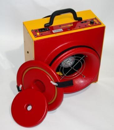
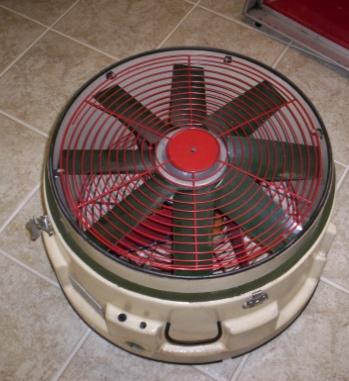
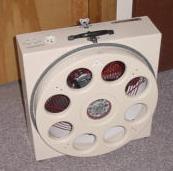
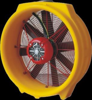
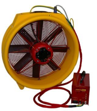
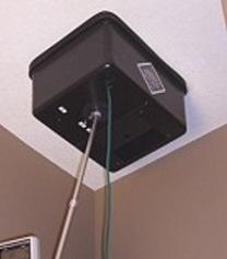
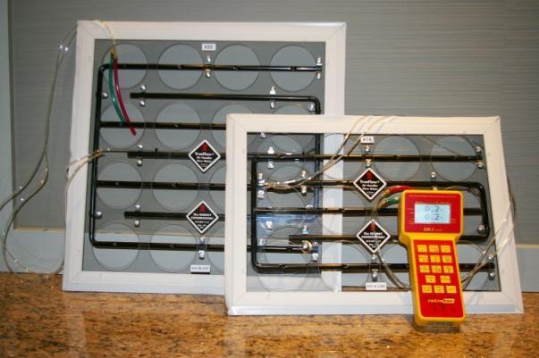
8 Analog Gauges Retrotec no longer manufactures or sells analog gauges. It is recommended that Door Fan systems using analog gauges be upgraded with a digital gauge. Retrotec manufactured three types of analog gauges: A 60 Pa gauge, which displays two ranges, 0 Pa to 60 Pa and 20 Pa to 40 Pa A 250 Pa gauge A 500 Pa gauge The E43 Door Fan system included an analog gauge clip which contains two 60 Pa Gauges and a 500 Pa gauge as shown on the second image in Figure 3. All Retrotec Door Fan systems can be connected to an analog gauge. Reading the pressure on an analog gauge is simply a matter of determining where the needle is pointing on the gauge. The needle indicates the pressure differential between the two pick-up points on the gauge. Note that it's important to zero the gauge before use, as readings will be incorrect if the gauge does not read zero before any tubes are attached. Figure 3. Digital and analog gauges display a pressure of 50.2 Pa (above); Retrotec s magnahelic gauge system (right). Page 8 of 61


9 2 DM-2 Digital Gauge Basics The DM-2 is Retrotec s digital micromanometer. It combines simple but comprehensive functionality, with intuitive controls and setup. The DM-2 is a dual channel digital micromanometer that always displays a pressure on Channel A, but will display pressure, flow, velocity, or leakage area on Channel B (depending on the Mode selected). To ensure accurate results, the DM-2 takes up to four pressure readings per second on each channel, and updates the information displayed on the screen every second. 2.1 Batteries The DM-2 can draw power from an AC power supply through the fan, directly from the wall outlet, or from four AA batteries. It is recommended that the gauge be used on battery power when possible. When battery power is insufficient to power the gauge, the warning message "Battery Too Low" will appear on the screen. The DM-2 includes the ability to recharge the batteries inside the gauge. The batteries will not start charging if the DM-2 is not turned on first (i.e. you must turn on the DM-2 first, and then plug in the AC power supply to charge the batteries). To prolong battery life, recharge the batteries only when they reach ¼ power (displayed on the battery status indicator). Do not operate the DM-2 with the AC power adapter or the Umbilical power cord attached after they are fully charged; this will significantly shorten the lifespan of rechargeable batteries. If the DM-2 must be operated with AC power, remove the batteries to prevent the shortening of the battery lifespan. The batteries are fully charged when the battery indicator is solid black. Allow the batteries to occasionally discharge completely to improve battery life. Install batteries The DM-2 comes with four AA NiMH rechargeable batteries. The batteries can be charged in the DM-2 with the AC power adapter, or in a compatible battery charger. The batteries should be charged for at least 8 hours each time. To completely charge the batteries, prior to using the gauge for the first time, 24 hours may be required. Page 9 of 61

10 To install batteries for the first time 1. Using a small Phillips screwdriver, open the lower back panel of the DM Install the four AA rechargeable NiMH batteries, making sure to align them correctly, and ensuring that the contacts are secure against both the positive and negative ends of each battery. 3. Replace the battery compartment panel and securely tighten the screw. 4. Plug the AC power adapter into a wall outlet and into the DM-2 DC power receptacle. 5. Turn the gauge on. 6. Allow the batteries to charge until the charging is complete (according to the battery status indicator). This may take up to 24 hours. Figure 4 Battery cage and four rechargeable batteries for the DM-2. Caution: Do not open the panel labeled No User Serviceable Parts Inside. Do Not Open. Doing so will void the calibration and warranty. Rechargeable or non-rechargeable (alkaline) batteries The standard NiMH batteries that are included with the DM-2 should last for two years of constant use. Every six months, it is worthwhile to remove the batteries and place them in a quality charger. This reconditions them and extends their life. Non-rechargeable batteries can also be used, but the charging circuit should be disabled to prevent accidental charging. Charging an alkaline battery may cause it to explode or leak. To replace the current batteries 1. Using a small Phillips screwdriver, open the lower back panel of the DM Remove the four old AA batteries and recycle them at a participating collection center. 3. Install four new AA batteries, making sure to align them correctly, and ensuring that the contacts are secure against both the positive and negative ends of each battery. The DM-2 can use either rechargeable NiMH batteries, or standard alkaline batteries. 4. Replace the battery compartment panel and securely tighten the screw. If a different type of battery is used (i.e. change from rechargeable to non-rechargeable), make sure to change the battery type in the Setup Menu of the DM-2. When "Not Rechargeable" is selected, the batteries, regardless of type, will not be charged. Attempting to charge non-rechargeable batteries can cause the batteries to leak, permanently damaging the DM-2. To select proper battery type 1. Press [Setup]. 2. Scroll to "Battery Type" and select "Rechargeable" or "Not Rechargeable" as needed. 3. Press [Exit]. Page 10 of 61

![Press [Exit] to view the main screen. The battery power indicator is in the top left. Figure 5.](/docs-images/94/118761525/images/11-1.jpg "Splash screen and the main screen with battery life indication in the top left.")
11 To view the remaining battery power: The DM-2 features a battery health indicator, displaying the current status of the battery on the main screen. The indicator is located in the upper-left corner of the display. 1. Turn the gauge on by pressing [On/Off]. 2. The splash screen is displayed. 3. Press [Exit] to view the main screen. The battery power indicator is in the top left. Figure 5. Splash screen and the main screen with battery life indication in the top left. Batteries will last longer if the backlight and auto-zero features are turned off, and if the gauge is manually turned off when not in use. Page 11 of 61

12 2.2 Gauge Overview The Retrotec DM-2 mark II gauge has: a connections panel, a display screen, and a keypad. The connections panel on the back of the gauge is where all external devices are connected to the DM-2. The display provides information on the current test mode and/or setup, as well as the device status and measurement values. The keypad is where the user inputs data to the DM-2, and controls the DM- 2 functions. The Connections Panel Figure 6. DM-2 back panel with pressure ports and electrical connections. The connections panel has the following: 1. Ethernet port 2. USB input 3. Reset button 4. Power input Pressure Ports: 5. Input B (+) 6. Reference B (-) 7. Reference A (-) 8. Input A (+) Page 12 of 61
 for rechargeable batteries only.")

13 The DM-2 Screen The Display Screen is where all measurement values are shown, as well as the current status of the device, and test configuration. Table 1. DM-2 Gauge keys and functions. Key Battery Health /Baseline Jog/Hold n Description Displays the battery health (degree of charge) for rechargeable batteries only. If Baseline has been activated, a pressure will appear that is deducted from the PrA value. Cycles between inactive as indicated by " " and "Hold" which will hold the display and control functions until Hold is turned off. Jog can be enabled when in Set Speed or Set Pressure mode. Displays the current value of the slope of the line along measurements are extrapolated. Can be set between 0.50 and A value of 0.65 is suggested for houses, 0.60 for ducts and 0.55 for leaky buildings with large holes and for large buildings. Page for more information 17 Time Displays the current Time Averaging setting: Off, 1s, 2s, 4s, 8s, 10s, 20s, 18 1m, 2m. Zero Displays the current Auto Zero status, On or Off. 18 Volume/Area Input Displays the current surface area, or enclosure volume setting, used for calculations involving per unit area. Speed Displays the current fan speed as a percentage. 19 Device Displays the current fan (also known as the Device). This must match the 15 fan that is in use. Range Config Displays the full Range configuration. The range selected must match 16 the Flow Range that is in use. Set Displays either the Set Pressure for Channel A or the Set Speed for the fan that the gauge will attempt to reach Mode Displays the current results being calculated by the gauge Page 13 of 61

14 The Keypad The DM-2 keypad provides access to all DM-2 settings and controls. Some keys have multiple functions. Keys labeled with an arrow [], [], [], and [] can be used to navigate around the menus, or to change the current selection. Pressing and holding a key automatically repeats the keystroke, and can be used to scroll through menus more quickly. 2.3 Resetting the Gauge If the DM-2 ever becomes frozen, or stops responding, it can be reset. Depending on the age of the gauge, there are two ways to reset a gauge. To reset a DM-2 with the Reset button 1. Press the Reset button. (The Reset button is located at the back of the gauge) 2. The gauge should turn on. 3. If pressing the Reset button on the DM-2 fails to reset the gauge, the batteries may need to be replaced or plugged into DC supply To reset a DM-2 without using the Reset button 1. Remove the back panel labeled "Battery Compartment". 2. Remove the batteries, and disconnect all other tubes or cords. 3. Wait five minutes. 4. Re-install the batteries. Page 14 of 61
15 2.4 Screen Contrast Older model DM-2s include the ability to change the screen contrast in order to improve visibility in different light conditions. Newer models have the voltage to the screen regulated so the contrast adjustment is not necessary. To change the screen contrast 1. If required, insert a small Phillips head screwdriver into the hole on the back marked "LCD Contrast". 2. Adjust the dial until the desired screen contrast is achieved. Page 15 of 61
 The On/Off (Backlight) key turns the gauge on and off, and allows the user to turn on the backlight, or preserve battery life and turn it off. Press [On/Off] to turn the DM-2 on.")

![Exit The Exit key allows the user to exit from certain screens, stop the fan, and clear entries. Press [Exit] after turning the gauge on, in order to clear the splash screen.](/docs-images/94/118761525/images/16-2.jpg "When in a Setup Menu, press [Exit] to back out of the current menu screen, or to cancel a menu selection.")
16 3 DM-2 Keypad Functions The DM-2 Keypad has 14 keys which control all of the DM-2 functions. On/Off (Backlight) The On/Off (Backlight) key turns the gauge on and off, and allows the user to turn on the backlight, or preserve battery life and turn it off. Press [On/Off] to turn the DM-2 on. The key needs to be held down for two seconds to turn the gauge off. The DM-2 is equipped with a backlight to improve visibility. The backlight turns on for a brief time when any key is pressed. When the DM-2 is on, pressing [On/Off] briefly will turn the backlight on permanently. Pressing it quickly again will turn the backlight off. Exit The Exit key allows the user to exit from certain screens, stop the fan, and clear entries. Press [Exit] after turning the gauge on, in order to clear the splash screen. When in a Setup Menu, press [Exit] to back out of the current menu screen, or to cancel a menu selection. While in Set Pressure or Set Speed mode, press [Exit] to immediately turn off the fan (the fan can also be stopped by setting the speed to zero). Pressing [Exit] at any time while in the main screen will cancel the Baseline as well. Enter (Volume/Area) Enter is a multi-application key that applies to several functions. Press [Enter] to select menu items, or to save input values. Depending on the Mode in use, a volume or area value may be required (Volume for Air Changes per hour, Area for any of the per Area results). Press [Enter] while the volume or area result is selected, to activate data entry for volume or area. Enter the appropriate value and press [Enter] again to save. Device Device refers to the fan or pressure measuring device being used to conduct the current test. It is important to make sure that the correct device is selected; the calculations for each of the results are based on system flow equations that are different for each device. Press [Device] to switch between the devices that have been enabled on the DM-2. Only the devices that have been enabled in the Setup Menu can be selected with the Device key. The currently selected device is displayed on the bottom right corner of the screen. The devices that can be selected for use with the DM-2 are listed in Table 4. When numerical input is required, the Device key is used to input the number zero. Page 16 of 61
 displays the user s selected units. (For information on selecting units, see Mode Setup in section 5.3).")
17 Mode The DM-2 mark II can display measurements and calculate results in a variety of units. The top result line ( Pressure ) always displays Channel A pressure in Pascals. The second result line( Mode ) displays the user s selected units. (For information on selecting units, see Mode Setup in section 5.3). Table 2 lists all the Modes, its units, and the results that are available on the DM-2 (note that some units are not available on all DM-2 models). Table 2. Possible results and selectable units for the DM-2 gauge. Mode Measures Units Pressure Flow pressure through the fan Pa, inches H 2 O, lb/ft 2 Flow Air flow through the fan CFM, l/s, m 3 /s, m 3 /h EfLA Effective Leakage Area calculated size of the total cm 2, in 2, ft 2 hole in the envelope. Usually taken at 4Pa in the US EqLA Equivalent Leakage Area calculated size of the total cm 2, in 2, ft 2 hole in the envelope. Usually taken at 10Pa in Canada Air Change Number of air changes per hour /h Flow/Area Air flow divided by the area of the enclosure CFM/ft 2, l/s/m 2, CFM/100ft 2, m 3 /h/m 2 EfLA/Area Effective Leakage Area divided by enclosure area in 2 /100ft 2, cm 2 /m 2 EqLA/Area Equivalent Leakage Area divided by enclosure area in 2 /100ft 2, cm 2 /m 2 Hole Flow The flow across a hole to be used to measure flow CFM, l/s, m 3 /s, m 3 /h through a known hole size (like exhaust fan or register) Velocity Air velocity (requires pitot tube) m/s, km/h, ft/s, ft/min, mph Velocity Flow Flow from velocity and area of duct CFM, l/s m 3 /s, m 3 /h Press [Mode] to scroll through the measurements that have been activated in the Setup menu. If all modes are activated then they will cycle through the results in the following order: Pressure Flow EqLA EfLA Air Changes Flow/Area EqLA/Area Hole Flow Velocity Velocity Flow When numerical input is required, the Mode key functions to input the number one. Range Config (fan Flow Ranges) Flow Ranges, are used to limit the air flow through a fan, so that the fan can achieve a measurable flow pressure, even when moving only a small amount of air (for more information, see Door Fan Operations Manual). Every fan that the DM-2 is compatible with, has a set of associated Flow Ranges. Select the correct Flow Range to ensure that the DM-2 performs accurate calculations, and displays correct results. Press [Range Config] to cycle through the Flow Ranges that are available for the currently selected device. Available Flow Ranges that are not used, can be removed from the menu. (See Enable and Disable Range Configurations in section 5.2) When numerical input is required, the Range Config key functions to input the number two. Page 17 of 61

![To navigate around the setup menu, use the up or down arrows []and [] to scroll through the menu. Use the left or right arrows [] and [] to choose between the different options.](/docs-images/94/118761525/images/18-1.jpg "The configuration is saved in non-volatile memory so the DM-2 will have the same configuration each time it is turned on.")
18 Setup The Setup key allows access to the Setup Menu, where the gauge is customized. For more information about navigating the menu and the options available, see Advanced DM-2 Options. Setup is used to enable or disable each of the various modes and devices, to configure the units of measurement for each mode, and to configure the operation of the DM-2. To navigate around the setup menu, use the up or down arrows []and [] to scroll through the menu. Use the left or right arrows [] and [] to choose between the different options. The configuration is saved in non-volatile memory so the DM-2 will have the same configuration each time it is turned on. The Setup menu provides access to the following settings: Full Screen Timeout specify the time before the screen changes to the full screen format Restore Settings used to restore the DM-2 to factory settings Language choose a language for the DM-2 menus and results Battery Type choose between rechargeable and non-rechargeable (alkaline) Display Version Info view the system version information n the slope of the line that the DM-2 will use to extrapolate results, when using function Power Down Hour the DM-2 will automatically turn off after the set number of hours Surface Area Unit specify the units that will be used for enclosure area Building Volume Unit specify the units that will be used for enclosure volume European, Separator specify whether to use a comma in place of a period in the numbers displayed Sig Figs Select either 2.5, 3.0, or 3.5 significant figures (e.g is displayed as 1135 for 3.5, 1130 for 3.0, and 1150 for 2.5) Device Setup enable or disable the use of compatible devices and associated Flow Ranges Mode Setup disable or specify the units for available modes When numerical input is required, the Setup key functions to input the number three. Baseline The Baseline function allows the user to measure the bias pressure, or Baseline pressure, under the current test conditions. Once measured, the DM-2 will automatically subtract the baseline pressure from all subsequently measured pressure readings, and will display only the adjusted pressures on the screen. Some buildings have an initial pressure imbalance between the indoors and outdoors, prior to any testing. The DM-2 averages the background pressure for the duration of the acquisition period. A 60 second baseline reading is typically enough to establish an accurate baseline measurement. If the building conditions change during the test, the baseline should be cleared, and a new measurement should be taken. Remember, if [Exit] is pressed to stop the fan, the baseline measurement will also be cleared, and will need to be re-taken. Page 18 of 61
![To establish a baseline pressure 1. Press [Baseline] to begin acquiring the background pressure. The gauge displays acquiring and begins to sample the background pressure.](/docs-images/94/118761525/images/19-1.jpg "While acquiring the pressure value, the gauge will continuously display the updated average pressure, and the sampling duration on the screen.")
19 To establish a baseline pressure 1. Press [Baseline] to begin acquiring the background pressure. The gauge displays acquiring and begins to sample the background pressure. While acquiring the pressure value, the gauge will continuously display the updated average pressure, and the sampling duration on the screen. The more the pressure is fluctuating, the longer the baseline samples for. 2. Press [Enter] to accept the current measurement, usually after approximately 60 seconds. If there is a lot of fluctuation, let the baseline acquire for longer than 60 seconds. The current baseline measurement, and the time taken to acquire it, is displayed at the bottom of the Main Screen. 3. Pressing [Exit] will clear the measurement. When numerical input is required, the Baseline key functions to input the number four. Time Avg When Time Averaging is active, the DM-2 will display results and pressures that are averaged over the time period selected, on both channels. Regardless of the averaging value, the display will update with a new value every second. This can provide significantly more accurate results. The DM-2 includes nine time averaging settings. Press [Time Avg] to scroll through the following time averaging settings: Off, 1s, 2s, 4s, 8s, 10s, 20s, 1m, and 2m. Caution: When changing the fan speed, set pressure, or taking a reading after making any other changes, wait for twice the time averaging period to elapse before taking a reading. Taking a reading too quickly can lead to recording incorrect results. Notice that the [Time Avg] key is located in the middle of all the arrow keys on the keypad. As a user friendly feature, while in the Setup Menu, the [Time Avg] key can be used to select menu items, just as you would using the [Enter] key. When numerical input is required, the Time Avg key functions to input the number five. Auto Zero Over time, the reading on Channel A and Channel B will start to drift away from zero. The longer the gauge is turned on, the larger this error can become. With Auto Zero on, the gauge will automatically zero the gauge every 8 seconds. In general, the DM-2 should be used with auto zero feature on. However, the function does consume extra battery power. Turning auto zero on, only at the start of each data acquisition cycle, will maximize gauge performance and data transfer rates. Press [Auto Zero] to turn Auto Zero on/off. When numerical input is required, the Auto Zero key functions to input the number six. Page 19 of 61

. 3. Press [Exit] to stop the fan, and cancel the Set Pressure. If the pressure is set to 0 Pa, the DM-2 will adjust the fan speed to bring the existing pressure to zero.")

20 Set Pressure The DM-2 can automatically control the fan speed on Q model systems to achieve a user set building pressure. This is the easiest method to achieve a specific test pressure. To use the Set Pressure function 1. Press [Set Pressure] to activate the automatic control. Input the desired building pressure using the DM-2 keypad and press [Enter] to start the fan. 2. The fan will accelerate until the input pressure has been reached, or the fan reaches 100% speed. The fan will continue to hold at that pressure, regardless of changes to the enclosure or room (i.e. opening/closing windows and doors, HVAC on/off, sealing, etc.). 3. Press [Exit] to stop the fan, and cancel the Set Pressure. If the pressure is set to 0 Pa, the DM-2 will adjust the fan speed to bring the existing pressure to zero. This can be used to normalize pressures during specific tests. See the Retrotec DucTester Operation & Testing manual for an example. When numerical input is required, the Set Pressure key functions to input the number seven. Set Speed The DM-2 can automatically control the fan speed on a Q model system to achieve a specific user-defined fan speed. To use the Set Speed function 1. Press [Set Speed] to activate the automatic control. 2. Input the desired speed using the DM-2 keypad. Speed is input as a percentage, and can be any value from Press [Enter] to start the fan. The fan will accelerate until the desired speed is achieved. 4. Press [Exit] to stop the fan and cancel the Set Speed, or press [Set Speed] [0] [Enter] to stop the fan. When numerical input is required, the Set Speed key functions to input the number eight. Jog/Hold Jog/Hold functions differently depending on which mode the DM-2 is currently in. The key has two functions: Hold Freezes the display with the data currently displayed on the screen. Nothing will change until the Jog/Hold key is pressed again to clear "Hold". Can be activated at any time. Allows the recording of instananeous results (eg. Flow, EqLA, PrB at pricisely the same time) Page 20 of 61
![The screen will display either "- - - - " or "Hold".To activate Hold Jog 1. Press [Jog/Hold] until "Hold" appears on the screen to freeze the screen and lock the data currently displayed. 2.](/docs-images/94/118761525/images/21-0.jpg "Press [Jog/Hold] again until \"----\" is displayed to unlock the screen. Enables the keypad arrows [] or []to adjust the Set Speed or Set Pressure up or down much like a traditional remote control.")
21 The screen will display either " " or "Hold".To activate Hold Jog 1. Press [Jog/Hold] until "Hold" appears on the screen to freeze the screen and lock the data currently displayed. 2. Press [Jog/Hold] again until "----" is displayed to unlock the screen. Enables the keypad arrows [] or []to adjust the Set Speed or Set Pressure up or down much like a traditional remote control. The screen will display either " ", "Jog" or "Hold" (when in Set Speed or Set Pressure mode). When not in Set Speed or Set Pressure mode, the DM-2 will not enter Jog mode (but Hold mode can be activated at any time). In Set Speed mode 1. Press [Jog/Hold] until "Jog" appears on screen. 2. Press [] or [] to increase or decrease the set speed in 1% increments. 3. Press and hold [] or [] to increase or decrease the set speed in 5% increments. 4. Press [Jog/Hold] again until "----" is displayed to resume normal operation. In Set Pressure mode 1. Press [Jog/Hold] until "Jog" appears on screen. 2. Press [] or [] to increase or decrease the set pressure in increments of 5 Pa, 0.02 in WC, or lbs/ft Press and hold [] or [] to increase or decrease the set pressure in increments of 10 Pa, 0.04 in WC, or 0.21 lbs/ft Press [Jog/Hold] again until "----" is displayed to resume normal operation. When numerical input is required, the Jog/Hold key functions to input the number Pressure Pressure key asks the DM-2 to calculate a result that would be achieved, if the desired test pressure were measured. The measured pressure will almost always be at least slightly over, or under, the exact test pressure making it difficult to report results that are standardised for a specific pressure. Pressure function performs a calculation called "extrapolation" which analyzes the currently measured results, and displays the results as if the test pressure was achieved. Press [@ Pressure] to toggle the DM-2 pressure extrapolation function on and off. The test pressure that is being extrapolated to is configured in the Setup Menu. Note: While the DM-2 is capable of extrapolating to any pressure, it is more accurate when the actual building pressure is closer to the desired extrapolation pressure. Page 21 of 61
22 Pressure function provides unique advantages over un-extrapolated results: There's no need to achieve an exact test pressure. The results on the screen will be very stable since results are extrapolated to a specific pressure. Results can be obtained, even if the test pressure cannot be reached. In Set Speed mode 1. Press [@ Pressure] to view the results at a particular pressure, as set in the Setup Menu. The units will change to indicate Pressure is on (e.g. CFM@50.0Pa). 2. Press [@ Pressure] again to view the current (non-extrapolated) results. The units will change to indicate Pressure is off (e.g. CFM). In Set Pressure mode 1. Press [@ Pressure] once to view the results at the current Set Pressure value. The units will change to indicate Pressure is on (e.g. CFM@40.0Pa). 2. Press [@ Pressure] again to view the results at Pressure, as set in the Setup Menu. Pressure value will change (e.g. CFM@50.0Pa). 3. Press [@ Pressure] again to view the current (non-extrapolated) results. The units will change to indicate Pressure is off (e.g. CFM). It is important to understand how to use this feature properly, as inaccurate results are likely if it is used incorrectly. The extrapolation feature works by estimating a typical leakage constant, and using it to calculate the results at the desired pressure. In general, if the desired test pressure is within +/- 10% of the actual measured pressure, Pressure will be accurate enough to record. This function should only be turned on and made active when in the appropriate situation do not leave it on for all tests as this may lead to inaccuracies. See below for examples. Example #1 - Inaccuracy A 50 Pa building pressure is desired, but only 20 Pa can be reached (due to severe leakiness). In this instance, the extrapolated results for flow '@ 50 Pa' do not represent the reality of the testing conditions and might be highly inaccurate. In the same situation, a 45 Pa building pressure is achieved. The extrapolated '@ 50 Pa' pressure is now much more accurate, and provides an acceptable result. Example #2 - Set Speed With the fan set at 100% speed, a building pressure of 46 Pa is reached. The gauge is setup to calculate flow in CFM, and Pressure setting Pa. Press [@ Pressure] once. Each time the key is pressed, the results alternate between displaying CFM and Page 22 of 61
23 Example #3 - Set Pressure The gauge is set up to measure flow in CFM, with Pressure Pa. The DM-2 is set to automatically control the fan speed to reach a test pressure of 75 Pa by using the Set Pressure function. Press [@ Pressure] once. Each time the key is pressed, the results rotate through 'CFM', and 'CFM@75Pa'. When numerical input is required, Pressure key functions to input a decimal point. Page 23 of 61

24 4 Using the DM-2 Gauge for Testing The DM-2 can be used for testing either on its own, or connected to a specialized, calibrated fan. Before it can be used for testing, it s important to know how to connect it properly. 4.1 Making the Connections The DM-2 mark II can be used with a Retrotec Door Fan and other similar devices. The Retrotec Umbilical cable includes all necessary tubes and cable connections. The pressure tubes, in the Umbilical cable, are color-coded. The pressure and hardware connection ports are also clearly labeled on the top of the gauge. Pressure port connections Retrotec has a specially designed connection port that makes a perfect seal and grips the tube well, but releases without tearing the tubing after multiple uses. This exclusive connector was designed by Retrotec to make contact with the both tube internally and externally with a shallow taper. The tube ends should be clean, and not stretched in order to make a proper connection. If the pressure tube is damaged, simply slice a short piece of tube off the end to ensure a clean fit. Tubing can crack in cold weather, but it can be warmed in hot water before being handled. Be careful to dry all water from the tubing prior to connecting. Green - Input B (+) - A higher pressure on this port and PrB reads positive. Yellow - Ref B (-) (fan) - A higher pressure on this port and PrB reads negative. Red - Ref A (-) (door) - A higher pressure on this port and PrA reads positive. Blue - Input A (+) - A higher pressure on this port and PrA reads positive. Figure 7. Pressure ports of the DM-2 gauge. Page 24 of 61
 port is used to connect the DM-2 to a computer equipped with Retrotec s FanTestic software.")
25 Hardware connections Speed Control Connects the DM-2 gauge to the fan using an Ethernet style cable. CAUTION: Never connect the DM-2 (or the fan) to an internet modem/router. USB PC The USB (Universal Serial Bus) port is used to connect the DM-2 to a computer equipped with Retrotec s FanTestic software. The computer can assume complete control of the gauge for data acquisition and control of advanced automated testing. LCD Contrast dial (older models) Adjust to increase or decrease the contrast of the display screen. Higher contrast settings will increase the display screen legibility in low-light situations, but will reduce battery life. Power Connects the gauge to an external power source using either the AC power adapter or power available from the fan (if available). To connect the DM-2 to a Retrotec fan or variable speed drive box 1. Locate the end of the Umbilical cable (this is the bundle of pressure tubing and control cable) with the shortest length of exposed pressure tubes and Ethernet cable. Plug the yellow Ethernet cable into the Speed Control port on the DM Plug colored tubes into the matching color-coded pressure ports on the top side of the DM-2. Ensure the tubes are snugly connected to the ports. Depending on the system, Umbilical cable can contain red, yellow, green, and/or blue tubes. Note: The Umbilical power cord should not be attached unless the DM-2 batteries are below one quarter power, and require recharging. 3. From the other end of the Umbilical cable, plug the yellow Ethernet cable into the port labeled Control on the fan top. 4. Attach the yellow pressure tube to the yellow bulkhead fitting labeled Ref B (fan) on the fan top. If available, the green pressure tube should be attached to the green bulkhead fitting labeled B (+). 5. Attach the Umbilical power cord to the port labeled DM-2 Power on the fan top, if the DM-2 requires recharging. 6. Pass the red pressure tube through the door panel and lay the end down out of the way of any air flow from the fan. Page 25 of 61
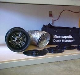
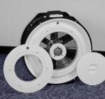
26 The Retrotec DM-2 can be connected to Minneapolis's Model 3 and Model 4 fans. To connect the DM-2 to a Minneapolis Model 3 or Model 4 Fan 1. Using the included Retrotec Umbilical cable, connect the yellow pressure tube from the yellow port of the DM-2 to the open port on the fan. 2. Some newer versions of the Model 3 and 4 contain an additional Reference port. If available, connect the green tube in the Umbilical cable from the green port on the DM-2 to the Reference port on the fan. 3. The power and control cables included in a Retrotec umbilical cannot be used when using a 3rd party fan. Make sure the batteries are fully charged, prior to beginning testing. 4.2 Conducting a Basic Test After making the necessary connections with the DM-2 (to the fan), follow these steps to begin a test. To conduct a test 1. Turn the gauge on by pressing [On/Off]. 2. Press [Exit] to exit the welcome splash screen. 3. Check the battery power before beginning a test to ensure the gauge has enough power to complete the test. (Plug the gauge in, recharge or replace batteries if needed). 4. Select the appropriate device to which the DM-2 is connected by pressing [Device]. 5. Select the appropriate Flow Range configuration for the fan by pressing [Range Config]. 6. Press [Mode] to select the required results to display. Note that the mode can be changed at any point during the test to view different results. 7. Select an appropriate time averaging value for the test conditions by pressing [Time Avg]. 8. Ensure that AutoZero is on. 9. Press [Baseline] to begin acquiring a baseline pressure reading. Press [Enter] after 60 seconds to set the baseline reading. 10. To view the results at a particular pressure, use the [@ Pressure] function. 11. Either press [Set Speed] to set the fan speed to a particular percentage, OR press [Set Pressure] to control the fan to a particular building pressure. 12. Press [Jog/Hold] once and use the arrows to increase or decrease the speed/pressure, or push it twice to hold the results on the display. Page 26 of 61
27 5 Gauge set up While the DM-2 can be run using the default settings, configuring the DM-2 for a specific fan system and testing protocol can save time and reduce the chance of making mistakes. Some systems may be ordered with the correct settings for a specific region and for the equipment being used. The Setup Menu provides access to a number of settings, including the Device and Mode Setup screens. 5.1 Setup Menu The Setup Menu contains access to two sub-menus and a list of other setup options: Full Screen Timeout Restore Settings Language Battery Type Display Version Info N Power Down Hour Surface Area Unit Building Volume Unit European, Separator Sig Figs Device Setup Mode Setup Notice that the [Time Avg] key is located in the middle of all the arrow keys on the keypad. As a user friendly feature, while in the Setup Menu, the [Time Avg] key can be used to select menu items, just as you would using the [Enter] key. Page 27 of 61

![Press [] or [] to select "Full Screen Timeout" in the list. Press [Enter]. 3. Input a time (in seconds) between 0-120. Press [Enter]. Press [Exit].](/docs-images/94/118761525/images/28-1.jpg "The DM-2 will not display the large format screen if a time period of '0' is used. Restore Settings At any time, the factory settings can be restored in the DM-2.")
28 Full Screen Timeout DM-2s that have firmware Version 3.0 or higher, have a large format screen, which automatically appears when no key press is recorded for a period of time. The length of time that must pass is determined by the Full Screen Timeout setting. To change the Full Screen Timeout time period 1. Press [Setup] to access the Setup menu. 2. Press [] or [] to select "Full Screen Timeout" in the list. Press [Enter]. 3. Input a time (in seconds) between Press [Enter]. Press [Exit]. The DM-2 will not display the large format screen if a time period of '0' is used. Restore Settings At any time, the factory settings can be restored in the DM-2. This will reset the gauge to have exactly the same settings that the gauge was shipped with. To restore the factory settings 1. Press [Setup] to access the Setup menu. 2. Press [] or [] to select "Restore Settings" in the list. Language 3. Press [] or [] to select Yes. The DM-2 can display information in the following languages: English, French, German, Norwegian, Swedish, and Latvian. Page 28 of 61
29 To change the language 1. Press [Setup] to access the Setup menu. 2. Press [] or [] to select "Language" in the list. 3. Press [] or [] to select the desired language. Battery Type The gauge supports both rechargeable and non-rechargeable (alkaline) batteries. It's important to correctly identify the battery type in the gauge setup, to prevent damage to the gauge. To select a battery type 1. Press [Setup] to access the Setup menu. 2. Press [] or [] to select "Battery Type" in the list. 3. Select the correct battery type for the installed batteries. Rechargeable batteries will not be charged when connected to a power supply if Non-Rechargeable batteries are selected. Display Version Info The current firmware and hardware version information can be found in the Setup Menu. To view version information 1. Press [Setup] to access the Setup Menu. 2. Press [] or [] to select "Display Version Info" in the list. 3. Press [Enter]. The DM-2 version information is displayed. 4. Press [Exit] to return to the Setup Menu. Page 29 of 61
30 n The n value is typically 0.65 for houses and 0.60 for ductwork. A wide open hole has an n of 0.5, meaning that when the pressure is quadrupled, the flow doubles. That is due to completely turbulent flow going through that hole (flow = square root of pressure, a constant for that particular hole). An n value of 1.0 represents tiny little holes, so small that the air would not be turbulent but rather would go through the holes as laminar flow. This means that when pressure is quadrupled, so will the flow. Houses and ducts are composed holes that will have both turbulent and laminar flow going through them. Duct holes tend to be slightly larger, whereas houses have more prevalent long tiny cracks, and therefore tend to have lower n values. These n values can be measured simply by doing a multi-point Door Fan or duct test. The result will be an n and a C (coefficient) so flow at any pressure can be calculated by using the equation: The gauge uses the n and C values to extrapolate for flows at other pressures. For example: If we guess at the n value of a duct as being 0.6 and measure 100 CFM at 20 Pa (by accident or by design), then the DM-2 will complete the following calculation for flow at 25 Pa: If the test pressure (20 in this case) is close to the desired reference pressure (25 Pa in this case), then the correction is small and the value of n does not play as large a role. However, if the test pressure is much higher or lower than the reference pressure, the error could be greater. Pressure feature is very useful for ensuring that results taken when the pressure was not adjusted perfectly are still accurate. To continue the above example: The flow at 20 Pa is 100 CFM. Actual n is 0.7, but this is unknown. Instead, 0.6 will be used. The DM-2 would calculate: Page 30 of 61
31 However, if it was known that n was 0.7, the flow at 25 should have been: This value is less than 3% off from what it should be. If the test pressure was within 1 or 2 Pa of the reference pressure of 25 Pa, Pressure reading would be exact. To change the n value 1. Press [Setup] to access the Setup menu. 2. Press [] or [] to select "n" in the list. Press [Enter]. 3. Input the new value between 0.5 and 1. Press [Enter]. Power Down Hour The Power Down Hour helps to maximize battery power by enabling the DM-2 to automatically turn off when it has been inactive for a set time period. The feature can be set to any value between 0 and 255 hours. Applying a 0 value will disable the Power Down feature, and the DM-2 will never automatically shut down. To change the Power Down Hour 1. Press [Setup] to access the Setup menu. 2. Press [] or [] to select "Power Down Hour" in the list. Press [Enter]. 3. Input the new value. Press [Enter]. Surface Area Unit For some results (e.g. Flow/Area, EqLA/Area, Hole Flow) an area measurement is required to calculate them. The units used for area can be configured. The area units may be set to square feet (ft 2 ), square meters (m 2 ), square centimeters (cm 2 ), or square inches (in 2 ). To change the Area units 1. Press [Setup] to access the Setup menu. 2. Press [] or [] to select "Surface Area Unit" in the list. Page 31 of 61
![3. Press [] or [] to select the desired units. Building Volume Unit For air change per hour results, volume measurements are required to calculated them. The units used for volume can be configured.](/docs-images/94/118761525/images/32-0.jpg "The volume units may be set to cubic feet (ft 3 ) or cubic meters (m 3 ). To change the Volume units 1. Press [Setup] to access the Setup menu. 2.")
32 3. Press [] or [] to select the desired units. Building Volume Unit For air change per hour results, volume measurements are required to calculated them. The units used for volume can be configured. The volume units may be set to cubic feet (ft 3 ) or cubic meters (m 3 ). To change the Volume units 1. Press [Setup] to access the Setup menu. 2. Press [] or [] to select "Building Volume Unit" in the list. 3. Press [] or [] to select the desired units. European, Separator The European decimal convention specifies how whole and fractional values are presented on the display and in captured data. European conventions use a comma (,) rather than a decimal point (.) to separate the integer portion of a number from the fractional portion. The DM-2 gauge supports both conventions. Select 'yes' to represent the decimal as a comma, choose 'no' to use a period. To change the European Separator units 1. Press [Setup] to access the Setup menu. 2. Press [] or [] to select "European, Separator" in the list. Sig Figs 3. Press [] or [] to select yes or no. The significant figures feature controls the number of significant digits displayed on the gauge. The available options are: 2.5 Two significant figures plus a third figure rounded to either 0 or 5. Page 32 of 61
33 3.0 Three significant figures. 3.5 Three significant figures plus a fourth figure rounded to either 0 or 5. Table 3. Example values displayed using each of the three significant figure options. Significant Figures Base Number To change the number of Significant Figures 1. Press [Setup] to access the Setup menu. 2. Press [] or [] to select "Sig Figs" in the list. 3. Press [] or [] to select 2.5, 3.0, or Device Setup The DM-2 mark II supports fan equipment from virtually every other calibrated fan manufacturer on the market. Table 4. List of compatible devices to be used with the DM-2. Device Mfr Device displayed Description Retrotec DU100 Obsolete DucTester DU200 Model Q32 DucTester 600/ /900 Obsolete fans 1000 Model 1000 systems with 0.75 hp yellow wheel rim style fans 2000 Model Q46 and Q56 systems with 0.75 hp yellow foam core fan 3000 Older Model Q4E, Q5E and QMG systems with 2 hp yellow foam core Door Fan 3000SR Model Q4E, Q5E and QMG systems with 2 hp yellow foam core Door Fan all fans are self-referencing (have green tube) Minneapolis DuctBlaster B Duct testing fan Model 3 (120V) Model 3 (240V) Model 4 (240V) Exhaust Fan 0.75 hp black wheel rim style fan Exhaust Fan Flow Meter measures air flow through residential exhaust fans between 10 and 124 CFM True Flow True Flow Grid measures flow through a residential air handler Infiltec E hp black wheel rim style fan Page 33 of 61

34 DU100/DU Fan 900 Fan 1000 Fan 2000 Fan 3000 Fan Mn Duct Blaster B Mn Model 3/4 Fan Mn Exhaust Fan Flow Meter Mn True Flow Grid Infiltec E3 Page 34 of 61

![From the main gauge screen, press [Setup] to access the Setup menu. 2. Press [] or [] to select "Device Setup" in the list. Press [Enter]. 3. Press [] or [] to select a device.](/docs-images/94/118761525/images/35-1.jpg "Press [] or [] to toggle between \"Yes\" or \"No\" next to each device. Selecting \"Yes\" for a device enables that device to be selected on the Main Screen. 4.")
35 Enable and Disable Devices To simplify the device selection process, it's possible to disable devices that will not be used. Disabled devices are saved in system memory, and will remain disabled upon subsequent uses. They can always be enabled if necessary. To enable/disable Devices 1. From the main gauge screen, press [Setup] to access the Setup menu. 2. Press [] or [] to select "Device Setup" in the list. Press [Enter]. 3. Press [] or [] to select a device. Press [] or [] to toggle between "Yes" or "No" next to each device. Selecting "Yes" for a device enables that device to be selected on the Main Screen. 4. Press [Exit] to return to the Setup Menu, press [Exit] again to return to the Main Screen. Page 35 of 61

36 Enable and Disable Flow Range Configurations It is also possible to enable and disable Flow Ranges for each of the devices being used. This will eliminate the need to scroll through each Flow Range when it can be determined which ones are the most well-used, cutting down on gauge setup time. Disabled Flow Ranges are saved in system memory, but can always be enabled if necessary. Table 5. DM-2 compatible devices and associated Flow Range configurations. Calibrated Fan Available Flow Ranges Retrotec 600/700 Open, 12, 8, 6, 2, 1 Retrotec 800/900 18F, 18R, 9, 5, 3, 1.4, 1.3, 1.2, 1.1, 0.1 Retrotec 1000 Open, A, B, C8, C6, C4, C2 Retrotec /2000/3000/3000SR Open, A, B, C8, C6, C4, C3, C2, C1, L4, L2, L1 Retrotec DU100/DU200 Open, Mid, Low Minneapolis DuctBlaster B Open, Ring 1, Ring 2, Ring 3 Minneapolis Model 3/4 Open, A, B, C, D, E Minneapolis Exhaust Fan E1, E2, E3 Minneapolis True Flow #14, #22 Infiltec E3 Open, 7 Holes, 4 Holes, 3 Holes, 2 Holes, 1 Hole To enable/disable Flow Range configurations in Device [Setup] 1. Enter the Device Setup menu by pressing [Enter] on Device Setup. 2. Select the device on which Flow Ranges need to be enabled/disabled and press [Enter]. 3. Press [] or [] arrows to turn the Flow Ranges on ("Yes") or off ("No"). Page 36 of 61

37 5.3 Mode Setup The DM-2 gauge is set to use a preset unit measurement configuration for each of the available modes. Table 6. Default mode set-up. Mode Settings Pressure Pa n/a Flow 50 Pa EfLA 4 Pa EqLA ft 10 Pa Air Changes 50 Pa Flow per Area 50 Pa EqLA per Area 50 Pa EfLa per Area 50 Pa Hole Flow Off n/a Velocity 1 Off n/a Velocity Flow 1 Off n/a The DM-2 mark II supports a number of calculations which can simplify the testing procedure. Some of these may be useful for specific testing needs. Use Mode Setup to customize the gauge to enable access to only specific results that will be used regularly. The configuration is permanently saved, but can be changed at any time. Once configured, the gauge will cycle through only those modes that are enabled in the Mode Setup menu. To configure Mode Setup 1. Press [Setup] to access the Setup menu. 2. Press [] or [] to select "Mode Setup" in the list. Press [Enter]. 3. Press [] or [] to select a mode. Press [] or [] to select the units associated with each mode. Select 'off' to disable that mode on the Main Screen. 4. Some modes have an Pressure. To change it, highlight the associated "@ Pressure", and press [Enter]. 5. Input the new value using the number keys on the keypad, and press [Enter] again. 1 Some versions of the Firmware do not support velocity and velocity flow. Page 37 of 61
38 5.4 Setting up your DM-2 for a NFPA Enclosure Integrity Test For a test to comply with the NFPA 2001, test results should be obtained in the units used in NFPA 2001 s Standard on Clean Agent Fire Extinguishing Systems (2008 edition).the units of results that should be enabled on the Setup Menu of the DM-2 are: Results DM-2 label Unit required for NFPA Pressure (Target Pressure) PrA Pa Flow Mode m 3 /s For simplicity purposes, the display of units for all other results are unnecessary and can be disabled on the gauge. The following step-by-step instructions can be followed to set up the DM-2 gauge for testing enclosure integrity in accordance to NFPA 2001: Setting up the units of results for a NFPA Enclosure Integrity test 1. Press [Setup]to enter the Setup menu 2. Press []or []to scroll through the list until Mode Setup is highlighted 3. Press [Enter] to enter the Mode Setup submenu 4. If Pressure is not highlighted, Press []or [] to scroll until Pressure is highlighted. 5. Use [] or [] to scroll until Pa is displayed 6. Scroll down to highlight Flow 7. Press [] or []to scroll until m 3 /s is displayed (your unit setting) 8. Scroll down to all other results in the Mode Setup menu, and use [] or [] to scroll until Off is displayed to disable all other results. 9. Press [Exit] once to exit from the Mode setup submenu and save the settings. Your DM-2 is now set up and ready for performing the NFPA 2001 Enclosure Integrity Test. Page 38 of 61
39 5.5 Performing an NFPA 2001 Enclosure Integrity Test (single point test as per 2008 edition) For an Enclosure Integrity test to comply with the NFPA 2001 s Standard on Clean Agent Fire Extinguishing Systems (2008 edition), Door Fan tests must be performed at four distinct points: two target pressures while depressurizing the enclosure, and two target pressures while pressurizing the enclosure. Target pressures required for NPFA Enclosure Integrity tests are: Test direction Deressurization Pressurization Target Pressure required for NFPA ( PrA ) -10 Pa -50 Pa +10 Pa +50 Pa The following step-by-step instructions can be followed to test enclosure integrity in accordance to NFPA 2001: 1. Set up your Door Fan system according to the Door Fan Operation Quick Guide. 2. Enter test conditions and dimensions into Retrotec s CA2001 software 3. Press [Mode] repeatedly until cfm appears beside the Mode label on the DM-2 4. Press [Time Avg] repeatedly until 4s appears beside the Time label on the DM-2 5. Press [Auto Zero] until On appears beneath the Zero label on the DM-2 6. Press [Device] until the name of the fan you are using appears beside the Device label on the DM-2 7. Press [Range] until the installed range appears beside the Range Config label on the DM-2 8. Press [Baseline], wait for 30 seconds, then press [Enter] 9. Press [Set Pressure] and enter one of the pressures listed in the table above 10. Achieve the first target pressure (using one of the two methods below), and enter the actual pressure read from the DM-2 gauge into CA Repeat steps 8-10 for the remaining Target Pressures from the table above. 12. If retention time is less than 10 minutes, use smoke from a Retrotec Air Current Tester to determine where leaks are, then seal the leaks. 13. Repeat test until retention time is greater than 10 minutes Page 39 of 61
40 Achieve the Target Pressure (Method 1) Using Set Pressure 1. Press [Set Pressure] and enter the target pressure. The fan should increase in speed and eventually stabilize with PrA approximately matching the input target pressure. 2. Enter PrA (pressure reading on Channel A, which is the building pressure or also called room pressure) and PrB (pressure reading on Channel B which is the flow pressure) from the DM-2 into CA2001. Achieve the Target Pressure (Method 2) Using Set Speed 1. Press [Jog/Hold] until Jog appears in the top center of the DM-2 display 2. Press []or [] to increase/decrease the fan speed until PrA approximately matching the input target pressure. (Quickly press and release for increments of 1% speed. Hold and release for increments of 5% speed) 3. Enter the PrA (pressure reading on Channel A which is the building pressure or also called room pressure) and the PrB (pressure reading on Channel B which is the flow pressure) from the DM-2 into CA2001. Page 40 of 61
41 5.6 Using the DM-2 to look for the locations of Leaks If your test does not comply (e.g. the retention time is less than what is required) with the Standard you are testing against (e.g. NFPA 2001), you need to search where the leakage locations are in the enclosure, seal up the leakages, and run the Enclosure Integrity Test again. The following instructions describe how to measure the total leakage area of the enclosure while sealing up leaks to pass the Enclosure Integrity Test: 1. If you are not already in Set Pressure mode (for example, you used Method 2 to achieve your target pressure) then press [Set Pressure] and input the current target pressure. 2. Press [Mode] until EqLA appears on the display beside the Mode label on the DM-2. (Enable EqLA in the Mode Setup if EqLA does not appear after cycling through [Mode]) 3. If the units for EqLA indicate ft 2 or in 50Pa, then press [@Pressure] until qualifier disappears. The DM-2 now displays the total leakage area of the enclosure. 4. If the displayed leakage is small, and the units for EqLA are in ft 2 you might want to switch the units to in 2 in the Setup menu. If the leakage is large and you are in in 2, you might want to switch the units to ft 2.) 5. Search for, locate, and temporarily seal holes in the enclosure. You will hear the fan slow down (less flow is required to achieve the target pressure when the room is tighter). 6. The retention tab in Retrotec s CA2001 software indicates the Maximum AllowableELA. If the EqLA reading on the DM-2 is greater than what is the Maximum Allowable ELA on CleanAgent 2001, you must continue sealing leaks in order to get the EqLA reading on the gauge to be less than what is the Maximum Allowable ELA is specified for your test on CleanAgent When the EqLA reading on the DM-2 is less than the Maximum Allowable ELA on the CleanAgent 2001, you have passed the Enclosure Integrity Test. (According to NFPA 2001, this translates to what the Maximum Allowable ELA should be to have a retention time of at least 10 minutes) Page 41 of 61
42 5.7 Setting up for a test with Alaska s AkWarm software 1. Press [Setup] to enter the Setup menu 2. Press [] or [] to scroll through the list until Mode Setup is highlighted 3. Press [Enter] to enter the Mode Setup submenu 4. Press [] or [] to scroll until Pressure is highlighted. 5. Press [] or [] to scroll until Pa is displayed 6. Press []to highlight Flow 7. Press [] or []to scroll until CFM is displayed 8. Press [] once to highlight EqLA 9. Use [] or [] to scroll until in 2 or ft 2 is displayed (this is an optional measurement foralaska AkWarm) 10. Press [] once to highlight Air Change 11. Use [] or [] to scroll until On is displayed (this is an optional measurement for Alaska AkWarm) 12. Scroll down to all other results in the Mode Setup menu, and use [] or [] to scroll until Off is displayed to disable all other results. 13. Press [Exit] once to return to the Setup submenu 14. Press [] to select n 15. Press [Enter] 16. Use the keyboard to set this value to Press [Enter] to accept this value 18. Press [] to select Power Down Hour 19. Leave at 2 (hours) or set to 0 to turn auto-power-down off. 20. Press [] to select Surface Area Unit 21. Press [] or [] to set to ft 2 (Note: AKWarm does not require the use of this parameter) 22. Press [] to select Building Volume Unit 23. Press [] or [] to set to ft 3 (Note: when you select Air Changes, you will enter volume in ft 3 ) 24. Press [] to select European, Separator 25. Press [] or [] to set to No 26. Press [] to select Sig Figs 27. Press [] or [] to set to Press [Exit] to exit the Setup menu and save these Setup settings. Your DM-2 is now set up for performing an Air Leakage Test with Alaska s AKWarm Software. Page 42 of 61


43 6 Field Calibration Gauge Calibration To verify the calibration of a gauge, the easiest method is to compare the readings of one channel with respect to the other channel. If the pressures are equal, then it is likely the gauge is accurate, because the chance of both channels being out of calibration by the same amount is very small. To perform a cross port check 1. Set both channels to measure pressure in Pascals. 2. Connect the Input port of Channel A to the Input port of Channel B using a small piece of tubing. The measured pressure on both channels should be within 1% of each other. 3. Disconnect the tubing, and then connect the Reference ports of both channels using the same piece of tubing. The measured pressure on both channels should be within 1% of each other. The same procedure can be followed to compare two gauges. The reading on both gauges should be the same. Figure 8. Gauge field check configurations (cross-channel checks (top), cross-gauge checks (bottom)). Page 43 of 61

. A similar procedure can be performed, by using a syringe to create a flow pressure.")
.")
44 When performing a gauge calibration with two gauges, if one gauge is known to be calibrated accurately, it can be used as a reference for the second gauge. In that case, the measured pressure on the tested gauge should be within 1% of the measured pressure on the calibrated gauge. To perform a T-connection flow pressure check 1. Using a T-connection, connect a pressure tube to the Input port of both Channel A and B. 2. Create a flow pressure on the end of the pressure tube. 3. Both Channel A and B should display the same measured pressure (or within 1%). A similar procedure can be performed, by using a syringe to create a flow pressure. This can be done with either one or multiple gauges. Although the procedure with a syringe is fairly widely used, it is not recommended by Retrotec for the following reasons: Requires equipment that most people don t have (Magnehelic gauge). Requires specific syringes (50 and 500 cc). It's an awkward procedure. Some part of the testing system of tubes and syringe will invariably be leaky and produce inaccurate results. To perform a syringe check Figure 9. Flow pressure check using a T-connection check. 1. Connect two gauges and a syringe following the set up in Figure Connect a Magnehelic gauge as shown. 3. Slowly pull air out of the syringe. Pressure readings on both gauges should increase. 4. Both gauges should display the same measured pressure. 5. Repeat steps 1-3 on the Input and Reference ports of both gauges. Figure 10. Syringe check setup. Page 44 of 61
45 7 Troubleshooting After getting a clear understanding of what pressure is and how it's measured, knowing the common causes of erroneous readings will increase the confidence of the results. It is often assumed the gauge must be regularly calibrated in order to get accurate readings, but this thought obscures the fact that most gauge problems do not result from incorrect calibrations. The following list provides approximate percent probabilities based on our experience for certain types of gauge problems. Notice that gauge calibration is one of the smallest, and even that can usually be eliminated, by following the gauge check procedures in this manual. Problem caused by Error frequency Error range Comments Tubing is crimped shut 5% 25 to 90% Usually noticeable because gauge does not move, but the blockage may be partial, which could cause an erroneous result. Water in tubing 10% 75-90% Possible only in wet areas. If gauges sent in to be repaired or calibrated, the water evaporates and the user never discovers the cause. Improper Device selected 2% 20 to 90% Not common because the wrong Flow Ranges will appear on the gauge. Improper Flow Range selected 5 to 25% 50% Very common unless gauges checked before and after tests to ensure the right Flow Range. Extrapolation pressure set incorrectly Improper use of reference tube for pressurization. Time averaging set too high or too low 10% 25% If the gauge shows a different extrapolation pressure [@ Pressure] then the results will be extrapolated to the wrong pressure 5% 25% Pressurization is seldom used, but if the technician is improperly trained, they may not set the equipment up properly for this test. 25% 5 to 10% If the gauge is fluctuating too much it will be difficult to read. If the time averaging is too high, the pressure may have changed but that change is not reflected in the reading. Wind 25% 10% These errors can be eliminated by long-term averaging or by multiple pressure pickups. Out of calibration 5% 1-50% Gauges can go out of calibration in a week or may take 10 years. It is impossible to tell unless the readings seem unreasonable. Out of calibration with regular checks 0.5% 1-2% Regular gauge checks can eliminate most of the calibration problems, by identifying large errors immediately, and before erroneous test results can be taken. It is unlikely that errors in excess of 2% would occur if the gauges checked before each use. Proper training can eliminate almost all of the above errors. Page 45 of 61


46 7.1 DM-2 Rechargeable Battery Problems The DM-2 is designed to recharge NiMH batteries in the gauge, eliminating the need to purchase a stand-alone battery charger. The charging cycle is designed to fully discharge batteries before recharging them. This can cause problems if the DM-2 is connected to a power plug for only brief periods of time. If the gauge exhibits any of the following conditions, it may be a problem with the rechargeable batteries: Short battery life Will not turn on Keys will not respond Loss of power during test The solution is to reset gauge and charge the batteries, or switch to nonrechargeable batteries. To charge the batteries: 1. Connect the AC power supply if rechargeable NiMH batteries are already installed. 2. Press the reset button on the back of the DM-2. The gauge turns on. Note: DM-2's that have firmware prior to version 2.28 will not have a reset button. To reset the gauge, remove all power connections, and the batteries, and wait at least 5 minutes. Then re-install the batteries and reconnect the charger. 3. Press [Exit] to show the main screen. 4. Display indicates batteries are charging. 5. Charge for at least 8 hours, or until battery icon stops moving. Problems can be avoided by taking a few simple steps. Leave DM-2 disconnected from a power supply until the batteries are depleted to one quarter power or less. Do not short-charge batteries by interrupting a charge in progress. Replace batteries with new AA NiMH batteries after 2 years. Page 46 of 61


47 7.2 Serial Number and Calibration Date Check It's recommended to check the serial number and calibration date on the DM-2 regularly. If the screen does not display a valid serial number and calibration date, please contact Retrotec tech support since your gauge may have switched over to default calibration values. This can be checked by connected your gauge to another gauge, port to port to ensure they read within 1%. 7.3 Moving Tubes Cause Fluctuating Pressures If the measured values on Channel A or B are fluctuating back and forth, in a way that doesn't correspond with any of the current testing conditions, it's possible that the pressure tube is moving. A moving tube can cause a significant error. For instance, a tube that is attached both to the gauge and to the fan, but is in the path of the fan's air flow, can swing back and forth. This swinging motion can easily cause fluctuations in the measured pressure. It's never a good idea to leave a tube hanging in the air, either between two points, or out of a window. The pressure tube should sit securely on the ground and be kept still as much as possible. The effects of a moving tube are very similar to the effects of wind on a tube, which is described below. To see the effect of a moving tube 1. Connect a pressure tube (10 feet or longer) to the blue port of the DM Set Time Averaging to one second. 3. Wave the end of the tube through the air. Notice the fluctuations. 4. Hold the end of the tube still, and swing the middle of the tube. Notice the fluctuations. Figure 11. The effect of a moving tube on pressure readings. Page 47 of 61
48 7.4 Wind causes a fluctuating pressure A wind blowing across the tip of a tube can cause significant error, even if the tube is not moving. One of the first things to notice when the wind is blowing is that it s very difficult to establish the test pressure. For example, when trying to establish 50 Pa, the wind will cause that pressure to go up to 55 Pa and down to 45 Pa, making it very difficult to take a reading. This type of problem can be rectified by using Pressure key, which will extrapolate the reading to the desired pressure regardless of the actual pressure being experienced at the moment. This does not solve the problem completely, but it does help. A second option is to increase the time averaging to 20 seconds or more. Be aware that if the fan is increasing or decreasing in speed, it will take 20 seconds at least for the gauge to register its reading. For example, if during the initial 10 seconds there was no building pressure whatsoever, and during the second 10 seconds there was 50 Pa, then the gauge will average that to 25 Pa. The rule of thumb here is to wait for at least double the time average period before a reading is taken. To learn how Time Averaging can negate the effects of wind 1. Use a fan to create an air stream. 2. Set Time Averaging to one second. 3. Place a tube, connected to the positive port, in the path of the air stream. 4. The gauge will display a pressure that fluctuates. Adjust the "wind" speed until the gauge is reading between 2 and 5 Pa. 5. Adjust Time Averaging to 20 seconds. 6. Notice that after 20 seconds, the gauge reading fluctuates significantly less. The Baseline feature can also be used to minimize the effects of wind, especially if the wind is relatively constant. To learn how establishing a Baseline can minimize the effects of wind 1. Use a fan to create an air stream that causes between 2 and 5 Pa pressure. 2. Set Time Averaging to one second. 3. Place a tube, connected to the positive port, in the path of the air stream. 4. Establish a Baseline pressure. 5. Notice that once a Baseline pressure is taken, the measured pressure drops closer to zero, negating the effects of the wind on the actual measured pressure. 6. Stop the fan. 7. Notice now that the measure pressure is negative, even though no pressure is being received by the gauge. With the Baseline feature still active, the gauge is compensating for a pressure that does not exist. Clear the baseline reading to eliminate this error. Another option is to ensure that the outdoor pressure pickup point is sheltered from the wind. In spite of standards that require tubes be attached to walls, this strategy does not work particularly well for limiting factor wind. What does seem to work is taking the outdoor pressure pickup tube 25 feet away from the building, and setting it in a flat area. Cover the end of the tube with a heavy flat sheet of halfinch plywood, for example, and the wind fluctuations will be reduced. Page 48 of 61

49 In extreme cases, wind dampening kits split the main pressure pickup point into either two or four directions, which will average the fluctuation across the building. Recent experience has shown that longer time averaging on a digital gauge is almost as effective as the four tube wind damping kit. When the time taken to set up the kit is taken into account, increasing the time averaging will actually save time. Overall, what works best is to have one tube running outdoors, where it is T d into two equal length tubes that are placed as far away from the building as possible. 7.5 Time Averaging User Errors While the Time Averaging feature is useful to help minimize the effects of wind, it can also cause problems if not used correctly. Whenever Time Averaging is on, it is important to wait at least twice the time averaging period before taking a reading. To learn how Time Averaging can cause error 1. Create a pressure on the positive port of Channel A (Input). 2. Set Time Averaging to one minute. 3. Wait until the pressure reading becomes stable. After one minute, Channel A should display the created pressure. 4. Remove the tube from Channel A, eliminating the pressure. 5. Notice that the gauge continues to display a pressure on Channel A, which slowly decreases. After one minute, the gauge should display no pressure difference. If a reading is taken from the gauge before the full time averaging period has passed, then the displayed pressure may not be accurate. 7.6 Large fixed errors A pinched pressure tube can create a very high reading on the gauge, which is erroneous. In other cases, a pinched tube will prevent the pressure measurement from reaching the gauge at all. In cases where tubes get stepped on, they are seldom sealed off completely, but will still cause the gauge readings to jump around. If the gauge begins to display an unusually high or unexplained pressure, check the tubing to ensure that it has not been compressed in any way. Figure 12. Errors in pressure reading from a pinched tube. Page 49 of 61


50 Water can also cause significant errors if a drop is pulled into the pressure tubes. It is very easy to get a water drop inside the end of a tube. Simply drag it over a shallow puddle of water, and a drop of water will get pulled into the tube by capillary action. Notice in the Figure 13 how one drop of water in the end of the tube is creating 190 Pascal pressure. It is possible to complete a Door Fan test with a water drop in the end of the tube. It will appear as if the fan is creating a pressure in the building, but in fact the results are way off. Particularly unusual behavior in the gauge could mean that there is water in the end of the tube. Be careful that no one steps on the tubes, or creates a kink in any of the lines while performing a test. If this happens, wait a few seconds for the effects to subside before taking any readings from the DM-2. Whip the end of the tube around to remove excess water. If this doesn t work (in extreme cases), water can be blown out from the other end. Be sure to not have the gauge connected when blowing water from the tube. Water can cause either a positive or a negative pressure, based on which way the drop of water is pulling. If a drop of water is facing downward, it pulls out of the tube, creating a negative pressure (as displayed in Figure 13). Point the tube upward, and the water drop falls back into the tube, creating a positive pressure. Figure 13. Water in the reference tube (left); high fixed pressure due to water (right). 7.7 Wrong Flow Range or Device selected If the results just don't make sense, check to make sure the correct Flow Range and device are selected. Each Device and Flow Range configuration has its own individual flow curve that is used to convert fan pressure into flow, and into the results selected under the Mode menu. If a test is completed with the incorrect Device and/or Flow Range selected, it is possible to salvage the data by using the customized flow charts provided in Appendix A. To determine correct flow if wrong Flow Range/device was selected: 1. Select the fan pressure for which a corrected flow value is needed. 2. Find this fan pressure value in the left column of the flow conversion tables in Appendix A. 3. Move across the row and record the flow value beneath the column heading with the actual Flow Range that was used. Note: Retrotec 2000 and 3000 series fans have the same flow curves. Page 50 of 61

 pressures on the gauge (greater than 2 Pa) are a good indication that wind may be a large source of error.")
51 7.8 No reference tube while pressurizing Model 1000, 2000, and 3000 fans are automatically referenced by the gauge, and do not require reference tubing (the green tube) for accurate results. Whenever the DM-2 measures a positive pressure, and knows that the fan flow is towards a greater pressure, it makes the necessary deductions from the flow pressure. Model 3000SR fans are self-referenced, and include a connection point for the green tube, which must be connected. 7.9 Windy conditions High fluctuations of bias (baseline) pressures on the gauge (greater than 2 Pa) are a good indication that wind may be a large source of error. In windy conditions, the house/room gauge will fluctuate. If the fluctuation is greater than 2 Pa due to wind buffeting, a wind damping system can be used to average out the wind, and get a more stable pressure reading. In addition to a number of suggestions for obtaining better performance from a single tube system (see 7.4), Retrotec offers two winddamping kits specifically designed to reduce the pressure fluctuations due to wind. The basic wind-damping kit consists of a dual-tube pressure averaging system and will work in wind conditions up to about 10 mph. The deluxe wind-damping kit (our Wild Wind Tamer ) consists of a four-tube engineered damping system that will provide damping results in winds up to 20 mph. Using a wind-damping kit 1. Set up the house/room gauge and red tube as normal. 2. Connect the open end to the T-connection on the basic wind-damping kit; connect the open tube to the output port on the deluxe wind-damping kit. 3. Place the wind-damping tubes away from the building to avoid the pressure pulse that gets created when the wind hits the wall. 4. Cover the end of the tubes with sheet material/a box to stop the wind, if required. Figure 14. Wind-damping kits; basic (left) and deluxe (right). Page 51 of 61
Operation Manual. rev Pressure Gauges DM-2
 Operation Manual rev-2013-12-02 Pressure Gauges DM-2 Copyright 2017 Retrotec All rights reserved. This document contains materials protected under International and Federal Copyright Laws. This book contains
Pressure Gauge Operation Manual
 rev-2017-12-01 Pressure Gauge Operation Manual For Model DM32 Made by Retrotec 1060 East Pole Road Everson, WA USA 98247 For support: Call 1(888) 330-1345 in USA +1 (360) 738-9835 outside USA support@retrotec.com
What is Pressure? Residential Pressure Measurement
 What you will learn What is pressure? The importance of pressure in houses Get to know your pressure gauge Using a digital pressure gauge Pressure gauge tests on houses Pressure gauge troubleshooting What
Operation Manual. rev Pressure Gauges DM32. Retrotec Inc.
 Operation Manual rev-2013-12-02 Pressure Gauges DM32 Retrotec Inc. Copyright 2012 Retrotec Inc. All rights reserved. This document contains materials protected under International and Federal Copyright
CONSERVATORY DIAGNOSTIC TOOLS TO MEASURE BUILDING PERFORMANCE
 for the DG-700 Pressure and Flow Gauge The ENERGY CONSERVATORY DIAGNOSTIC TOOLS TO MEASURE BUILDING PERFORMANCE The Energy Conservatory 2801 21 st Ave. S., Suite 160 Minneapolis, MN 55407 Ph.: (612) 827-1117
Building Official's Guide to Duct Testing based on 2009 IECC
 Why test ducts? Leaky ducts pose health, safety and comfort problems and account for about 25% of the total energy lost in a typical house. Because it s by far the most cost effective way to save energy
Scoreboard Operator s Instructions MPC Control
 Scoreboard Operator s Instructions MPC Control Some features on the keyboard overlay may not be included on the particular model being operated. Since 1934 Retain this manual in your permanent files 1/21/2011
WELCOME TO THE REVOLUTION
 USER GUIDE WELCOME TO THE REVOLUTION THANK YOU FOR CHOOSING THE GCQUAD We listened to what you wanted - and created the most accurate, versatile and game-enhancing ball and club analysis solution available
Copyright 2004 by the Thomas G. Faria Corporation, Uncasville CT No part of this publication may by reproduced in any form, in an electronic
 Copyright 2004 by the Thomas G. Faria Corporation, Uncasville CT No part of this publication may by reproduced in any form, in an electronic retrieval system or otherwise, without the prior written permission
ECHO MANUAL WARNING. L B A ltim e te rs. ECHO is a trademark of LB Altimeters, Denmark
 ECHO MANUAL L B A ltim e te rs ECHO is a trademark of LB Altimeters, Denmark LB Altimeters operates a policy of continuous development Therefore, we reserve the right to make changes and improvements to
Troubleshooting Guide: 640 Pediatric Exam Table with Midmark Scale
 Troubleshooting Guide: 640 Pediatric Exam Table with Midmark Scale Contents Description Refer To: Scale Troubleshooting Chart Troubleshooting Error Codes Error Messages Adjustments / Repair Procedures
ASE SOLVENT CONTROLLER INSTALLATION INSTRUCTIONS Dionex Corporation
 ASE SOLVENT CONTROLLER INSTALLATION INSTRUCTIONS 2000 Dionex Corporation Document No. 031277 Revision 03 April 2000 2000 Dionex Corporation All rights reserved worldwide. Printed in the United States of
Blower Door Operation Manual
 Multiple-Fan rev-2016-03-14 Blower Door Operation Manual For Series 300, 5000 and 6000 systems Retrotec Inc. 2016 Page 1 of 31 Copyright 2013-2015 Retrotec Inc., All rights reserved. This document contains
Pegas 4000 MF Gas Mixer InstructionManual Columbus Instruments
 Pegas 4000 MF Gas Mixer InstructionManual Contents I Table of Contents Foreword Part I Introduction 1 2 1 System overview... 2 2 Specifications... 3 Part II Installation 4 1 Rear panel connections...
GPS OWNERS MANUAL. All PowaKaddy electric trolleys have been awarded the Quiet Mark by the Noise Abatement Society
 OWNERS MANUAL GPS All PowaKaddy electric trolleys have been awarded the Quiet Mark by the Noise Abatement Society The PowaKaddy Update App Available to download from the Apple App store and Google Play
Operation Manual. Software. FanTestic Integrity (complying with NFPA 2001) rev
 rev") Operation Manual rev-2017-04-26 Software FanTestic Integrity (complying with NFPA 2001) Copyright 2017 Retrotec All rights reserved. This document contains materials protected under International and Federal
Operation Manual rev-2017-04-26 Software FanTestic Integrity (complying with NFPA 2001) Copyright 2017 Retrotec All rights reserved. This document contains materials protected under International and Federal
RM-80 respiration monitor
 RM-80 respiration monitor User Manual September 18, 2015 0025-003M 950 North Hague Avenue Columbus, Ohio 43204-2121 USA Sales: sales@colinst.com Service: service@colinst.com Phone: (614) 276-0861 Fax:
Touch Screen Guide. OG-1500 and OG Part # T011
 Touch Screen Guide OG-1500 and OG-2000 Part # 9000000.T011 Effective 11/2010 External View Internal View 1. Transducer Banks 2. Oxygen Sensor 3. PLC These are the two manifolds with three (3) transducers
User's Manual. Heavy Duty Dissolved Oxygen Meter. Model
 User's Manual Heavy Duty Dissolved Oxygen Meter Model 407510 Introduction Congratulations on your purchase of Extech's Heavy Duty Dissolved Oxygen / Temperature Meter which simultaneously displays Dissolved
Operator Quick Guide ORBISPHERE 3654
 Operator Quick Guide ORBISPHERE 3654 Revision H - 14/03/2008 Operating Information About this Guide The information in this guide has been carefully checked and is believed to be accurate. However, Hach
AIR FLOW ANEMOMETER INSTRUCTION MANUAL
 AIR FLOW ANEMOMETER INSTRUCTION MANUAL Thank you for purchasing our company Air Flow Anemometer. This manual provides relative information on how to use the Air Anemometer and warning in operation Please
CONSOLE-320 ENGLISH. 230A: CONSOLE-320 with cable data output Item 230B: CONSOLE-320 with cable + wireless radio data output
 CONSOLE-320 Item 230A: CONSOLE-320 with cable data output Item 230B: CONSOLE-320 with cable + wireless radio data output Table of contents 1. INTRODUCTION...2 1.1 Power supply...2 1.2 Connections...2 1.3
OWNER S MANUAL. All PowaKaddy electric trolleys have been awarded the Quiet Mark by the Noise Abatement Society
 OWNER S MANUAL All PowaKaddy electric trolleys have been awarded the Quiet Mark by the Noise Abatement Society Thank you for purchasing the new PowaKaddy. We hope you enjoy your new FW7s GPS trolley and
TESTING AT VERY LOW FLOWRATE
 TESTING AT VERY LOW FLOWRATE Author : Valérie Leprince (PLEIAQ) for BCCA npo August 2018 Buildings are becoming tighter and tighter, leading to test at very small flowrate compared to the volume of the
MicroTim XB. User Manual. Precision Digital Barometric Altimeter / Barometer / VSI. Document Revision 1.0 Firmware Version 3.0
 MicroTim XB Precision Digital Barometric Altimeter / Barometer / VSI User Manual Document Revision 1.0 Firmware Version 3.0 Table of Contents Table of Contents...2 1 General Operation...5 1.1 Altitude
OC Panel High Limit Aquastat Kit, Manual Reset p/n
 OC Panel High Limit Aquastat Kit, Manual Reset p/n 233202 Instruction Sheet APPLICATION The OC (Option Control) Panel High Limit Aquastat Kit provides electronic temperature sensing in a UL limit-rated
TR Electronic Pressure Regulator. User s Manual
 TR Electronic Pressure Regulator Page 2 of 13 Table of Contents Warnings, Cautions & Notices... 3 Factory Default Setting... 4 Quick Start Procedure... 5 Configuration Tab... 8 Setup Tab... 9 Internal
Operating Instructions Part No
 DIGITAL AUTOMATIC TYRE INFLATOR Operating Instructions Part No. 11.0578 Thank you for selecting this Jamec Pem Automatic Tyre Inflator. Please read this manual before carrying out any installation or service
Operating Instructions for Cobra and Lynx Duct Leakage Testers
 Operating Instructions for Cobra and Lynx Duct Leakage Testers Table of Contents Introduction Introduction... 2 Safety Precautions Safety Precautions.. 2 Prior to Testing System Preparation.. 4 Power Requirements...
Heavy Duty Dissolved Oxygen Meter
 User's Manual Heavy Duty Dissolved Oxygen Meter Model 407510 Test Equipment Depot - 800.517.8431-99 Washington Street Melrose, MA 02176 FAX 781.665.0780 - TestEquipmentDepot.com Introduction Congratulations
OPERATING INSTRUCTIONS FOR
 OPERATING INSTRUCTIONS FOR MODEL 2240LED www.sportablescoreboards.com 1 Table of Contents CONTROLLER DEFINITIONS... 3 COMMUNICATION CABLES... 4 CONNECTING A HARD WIRED CABLE:... 4 CONNECTING A WIRELESS
HPICAL Operation & Data Logging Procedures. Click spacebar to advance through slides 1
 HPICAL-15000 Operation & Data Logging Procedures Click spacebar to advance through slides 1 WARNING Always wear proper safety equipment when using high pressure equipment. Do not exceed 125 psi air pressure.
OPERATING INSTRUCTIONS FOR
 OPERATING INSTRUCTIONS FOR MODEL 1232 LED www.sportablescoreboards.com 1 Table of Contents CONTROLLER DEFINITIONS... 3 COMMUNICATION CABLES... 4 Connecting a Hard Wired Cable... 4 Connecting a Wireless
GNX 20/21. Owner s Manual
 GNX 20/21 Owner s Manual March 2016 190-01659-00_0C All rights reserved. Under the copyright laws, this manual may not be copied, in whole or in part, without the written consent of Garmin. Garmin reserves
Roller AC Servo System
 Safely Instruction Roller AC Servo System HMI-15 User Manual Please read this manual carefully, also with related manual for the machinery before use the controller. For installing and operating the controller
A4 Operation Manual. Fig.1-1 Controller Socket Diagram
 A4 Operation Manual Safety Instruction Please read this manual carefully, also with related manual for the machinery before use the controller. For installing and operating the controller properly and
COMBAT SWIM BOARD. RJE International, Inc. RJE International Feb 1, TAC-300 Revision 6
 COMBAT SWIM BOARD RJE International, Inc. YOUR SOURCE FOR DIVER NAVIGATION AND UNDERWATER RELOCATION EQUIPMENT RJE International Feb 1, 2017 12 TAC-300 Revision 6 RJE International, Inc. 15375 Barranca
PTG100 Precision Test Gauge
 PTG100 Precision Test Gauge User Manual PD1007 Rev B 03/28/2014 Palmer Instruments Inc. 234 Old Weaverville Road Asheville, NC 28804 Toll Free: 800-421-2853 Phone: 828-658-3131 Fax: 828-658-0728 Email:
MP15 Jockey Pump Controller
 Setup and Operating Instructions MP15 Jockey Pump Controller This manual provides general information, installation, operation, maintenance, and system setup information for Metron Model MP15 Jockey Pump
GNX 20/21. Owner s Manual
 GNX 20/21 Owner s Manual Table of Contents Introduction...1 Device Overview... 1 Using the Race Timer... 1 Profiles... 1 Selecting a Profile... 1 Restoring Profiles to their Default Settings... 1 Instrument
GNX 120/130. Owner s Manual
 GNX 120/130 Owner s Manual March 2016 190-01846-00_0B All rights reserved. Under the copyright laws, this manual may not be copied, in whole or in part, without the written consent of Garmin. Garmin reserves
A4s Operation Manual
 A4s Operation Manual Safety Instruction Please read this manual carefully, also with related manual for the machinery before use the controller. For installing and operating the controller properly and
Approach. S3 Owner s Manual. May _0B Printed in Taiwan
 Approach S3 Owner s Manual May 2012 190-01467-00_0B Printed in Taiwan All rights reserved. Under the copyright laws, this manual may not be copied, in whole or in part, without the written consent of Garmin.
ACV-10 Automatic Control Valve
 ACV-10 Automatic Control Valve Installation, Operation & Maintenance General: The Archer Instruments ACV-10 is a precision automatic feed rate control valve for use in vacuum systems feeding Chlorine,
The HumiSys. RH Generator. Operation. Applications. Designed, built, and supported by InstruQuest Inc.
 The HumiSys RH Generator Designed, built, and supported by InstruQuest Inc. Versatile Relative Humidity Generation and Multi-Sensor System The new HumiSys with single or dual RH probes capabilities is
Race Screen: Figure 2: Race Screen. Figure 3: Race Screen with Top Bulb Lock
 Eliminator Competition Stand Alone Mode - Instruction Manual Main Menu: After startup, the Eliminator Competition will enter the Main Menu. Press the right/left arrow buttons to move through the menu.
A full user manual detailing the additional features of the Neo XS is available for downloading at
 Buttons and Functions Golf Menu 1 Lit #: 10-13 English See Page 8 for Language Setting Instructions Up 3 1. www.bushnell.igolf.com Select 4 2 Menu Down 5 1. Golf Menu Button: View Golf Menu 2. MENU Button:
User Manual. ENGLISH Pages FRANÇAIS Pages ESPAÑOL Páginas DEUTSCH Seiten 53-69
 User Manual ENGLISH Pages 1-18 FRANÇAIS Pages 19-35 ESPAÑOL Páginas 36-52 DEUTSCH Seiten 53-69 LIT# LD2-160212 LD2-Full_Manual Rev18 Thank you for choosing the GolfBuddy LD2. The GolfBuddy LD2 is the first
System 6 Water Polo. For the System 6 Sports Timer Software User Guide. F872 Rev
 System 6 Water Polo For the System 6 Sports Timer Software User Guide F872 Rev. 20171114 Customer Service Department www.coloradotime.com Email: customerservice@coloradotime.com Phone: 970-667-1000 Toll
COMBAT SWIM BOARD. RJE International, Inc. RJE International January 16, TAC-300 Revision 4
 COMBAT SWIM BOARD RJE International, Inc. YOUR SOURCE FOR DIVER NAVIGATION AND UNDERWATER RELOCATION EQUIPMENT RJE International January 16, 2017 RJE International, Inc. 15375 Barranca Pkwy, Ste. I-112,
Electronic Commissioning Unit. Instructions
 Electronic Commissioning Unit Instructions 1. The Comdronic AC6 Electronic Commissioning Unit 2. Health and Safety 3. Description of Unit 4. Connection and Set-up Procedure 5. Menu System a. Main Menu
The process of measuring air
 Measuring Leakage in High-Rise Buildings By Colin Genge The process of measuring air leakage to the outside in singlefamily homes is fairly well known among home performance professionals and anyone familiar
Misaligned Folds Paper Feed Problems Double Feeds Won t Feed FLYER Won t Run iii
 Operator s Manual Table of Contents Operator Safety... 1 Introduction... 2 Unpacking and Setup... 3 Unpacking... 3 Setup... 4 FLYER Overview... 5 FLYER Diagram... 5 Capabilities... 5 Control Panel... 6
RPS900W Redundant Power Supply. Installation Guide.
 RPS900W Redundant Power Supply Installation Guide www.edge-core.com Installation Guide RPS900W Redundant Power Supply Single DC Output Port with Dual Output Voltages RPS900W E10013-CS-R01 1500000081A
TEL/jlRE" Introduction. Display Features and Modes. Startup Procedure. Power-Up Procedure. Adjustment Modes
 TEL/jlRE" Introduction The Telaire 7001 CO 2 /T emperature monitor (shown in Fi gt u e 1 below) is an easy to use hand-held instnunent, which provides stable and highly accurate readings due to Telaire
BAPI Pressure Line of Products - FAQs
 Table of Contents 1. Several manufacturers produce pressure transmitters, why should I purchase from BAPI?... p. 2 2. BAPI makes several styles of pressure transmitters. What are the features of each?...
User s Guide. Pressure Controller for liquid delivery systems
 Flow Control User s Guide Pressure Controller for liquid delivery systems Precise Pressure Control throughout the experiment Flow control Compatible with any perfusion system Ideal for Small Volume Delivery
CONSUMER MODEL INSTALLATION GUIDE
 CONSUMER MODEL INSTALLATION GUIDE System requirements Windows System Requirements To use your TOMI and its software, your system should have: A Microsoft Windows compatible PC with a Pentium IV processor
RAM 4021-PR. Operation Manual. Worldwide Manufacturer of Gas Detection Solutions
 RAM 4021-PR Operation Manual Worldwide Manufacturer of Gas Detection Solutions TABLE OF CONTENTS RAM 4021-PR For Your Safety... 2 Description.... 2 Setup Mode.... 2 Lights/Alarms.... 3 Operation.... 4
Operating Instructions Part No
 DIGITAL AUTOMATIC TYRE INFLATOR Operating Instructions Part No. 11.0545 Thank you for selecting this Jamec Pem Automatic Tyre Inflator. Please read this manual before carrying out any installation or service
Model 130M Pneumatic Controller
 Instruction MI 017-450 May 1978 Model 130M Pneumatic Controller Installation and Operation Manual Control Unit Controller Model 130M Controller is a pneumatic, shelf-mounted instrument with a separate
MODEL 100 NITROGEN INFLATION CART
 MODEL 100 NITROGEN INFLATION CART Installation & Operation Information Branick Industries, Inc. 4245 Main Avenue P.O. Box 1937 Fargo, North Dakota 58103 REV120106 P/N: 81-0113 TABLE OF CONTENTS SAFETY
STANDARD OPERATING PROCEDURES. Andersen Instruments Federal Reference Method (FRM) Ambient Particulate (PM 10 /PM 2.
 Ambient Particulate (PM 10 /PM 2.") STANDARD OPERATING PROCEDURES Andersen Instruments Federal Reference Method (FRM) Ambient Particulate (PM 10 /PM 2.5 ) Sampler (RAAS) AMBIENT AIR MONITORING PROGRAM for the 130 LIBERTY STREET DECONSTRUCTION
STANDARD OPERATING PROCEDURES Andersen Instruments Federal Reference Method (FRM) Ambient Particulate (PM 10 /PM 2.5 ) Sampler (RAAS) AMBIENT AIR MONITORING PROGRAM for the 130 LIBERTY STREET DECONSTRUCTION
Pneumatic high-pressure controller Model CPC7000
 Calibration technology Pneumatic high-pressure controller Model CPC7000 WIKA data sheet CT 27.63 Applications Healthcare and avionics industry Industry (laboratory, workshop and production) Transmitter
Device overview. 6 Breathing circuit connection. Note: When the remote control foot pedal is connected, the manual switch is disabled.
 CoughAssist E70 Quick start guide 1 2 3 4 5 Device overview Starting therapy Modifying therapy settings Monitoring view and icons 6 7 Suggested guidelines for therapy Device menu Mask fitting 1 Device
Golf Team Challenge. Product: EA SPORTS PGA TOUR Software Version: Release Date: 10/18/06. Revised 4/21/2009
 Product: EA SPORTS PGA TOUR Software Version: 4.0.0 Release Date: 10/18/06. Revised 4/21/2009 Golf Team Challenge This document describes the new play modes and Operator Menus in EA SPORTS PGA TOUR Golf
CircuFlow Quick Setup Guide
 CircuFlow 5200 Quick Setup Guide LB04.0001 Rev B 20140314 TABLE OF CONTENTS Setup Therapy Setup Gradient Mode Pressure Mode Lock Device Unlock Device Treatment 03 04 05 08 11 12 13 02 SETUP 01 01 Open
Blower Door Operation Manual
 Multiple Fan rev-2017-04-20 Blower Door Operation Manual For Series 1000 and 3000 systems Copyright 2013-2017 Retrotec, All rights reserved. This document contains materials protected under International
RAM Operation Manual. Worldwide Manufacturer of Gas Detection Solutions
 RAM 4021 Operation Manual Worldwide Manufacturer of Gas Detection Solutions TABLE OF CONTENTS RAM 4021 For Your Safety... 2 Description.... 2 Setup Mode.... 2 Lights/Alarms.... 3 Operation.... 4 Calibration....
PTS 2000Version User s Manual. Operators Manual
 PTS 2000Version 4.0.. User s Manual Operators Manual ... Copyright Puritan-Bennett Corporation 1999, 2003. All rights reserved. The information contained in this manual is the sole property of Puritan
M104 Series: Digital Manometer: 0.1 % of Full Scale
 M104 Series: Digital Manometer: 0.1 % of Full Scale Copyright 2008 Meriam Content M104 Series: Digital Manometer:...1 0.1 % of Full Scale...1 Content... 2 General information...4 Glossary... 5 General
Mass Spec will not Autotune
 Mass Spec will not Autotune Applies to 5973A/N MSD What could be the problem? There could be several things that would cause your Mass Spec not to Autotune. The most common, easily corrected Autotune problems
Stand-Alone Bubble Detection System
 Instruction Sheet P/N Stand-Alone Bubble Detection System 1. Introduction The Bubble Detection system is designed to detect air-bubble induced gaps in a bead of material as it is being dispensed. When
Getting to know your Sureshotgps micro V3
 Getting to know your Sureshotgps micro V3 Battery State Symbol Satellite Signal Shows distance to front, centre and rear of each green Hole Number Real Time Power on and Enter Key Down (backward) Key 1
OxyScan Graphic. Operating Instructions. UMS Micro-oxygen sensor 501. Microprocessor instrument
 OxyScan Graphic Operating Instructions UMS Micro-oxygen sensor 501 Microprocessor instrument Introduction Thank you for choosing the UMS Micro Oxygen Sensor 501 - a highly advanced product! Please read
MODEL 6600 Rev. B4 USER'S MANUAL LAVERSAB INC., 505 GILLINGHAM LANE. SUGAR LAND TX (281) FAX: (281)
 FAX: (281)") MODEL 6600 Rev. B4 USER'S MANUAL LAVERSAB INC., 505 GILLINGHAM LANE. SUGAR LAND TX 77478 (281) 325-8300 FAX: (281) 325-8399 Email: aservice@laversab.com Document Number : 9051 REV B4 Date: June 07, 2011.
MODEL 6600 Rev. B4 USER'S MANUAL LAVERSAB INC., 505 GILLINGHAM LANE. SUGAR LAND TX 77478 (281) 325-8300 FAX: (281) 325-8399 Email: aservice@laversab.com Document Number : 9051 REV B4 Date: June 07, 2011.
Air Bubbler Depth Gauge DG2200 Installation and Reference Manual
 Air Bubbler Depth Gauge DG2200 Installation and Reference Manual Rev. 3.2.2 06/2011 Installation and Reference Manual Page 2 Contents Chapter 1: Installation and Overview... 3 1.1 DG2200 Location Diagram...
APA software instruction manual
 1. Starting the program In order to start the control software for the APA device press APAxx shortcut located on the desktop of the supplied computer. XX corresponds to the current software version. When
New product release. Universal Rebreather Monitor (URBM) Single O2 cell and Dual HP package
 Single O2 cell and Dual HP package") New product release Closed Circuit Research is pleased to announce the launch of our range of Universal Rebreather Monitors Key features and benefits include: Universal Rebreather Monitor (URBM) Single
New product release Closed Circuit Research is pleased to announce the launch of our range of Universal Rebreather Monitors Key features and benefits include: Universal Rebreather Monitor (URBM) Single
GNX 20/21 Owner s Manual
 GNX 20/21 Owner s Manual February 2014 190-01659-00_0B Printed in Taiwan All rights reserved. Under the copyright laws, this manual may not be copied, in whole or in part, without the written consent of
OPERATOR S MANUAL Ar-Gone Weld Gas Analyzer
 July 2011 OPERATOR S MANUAL Ar-Gone Weld Gas Analyzer WARNING! Before operating this product, read and understand this Operator s Manual. Become familiar with the potential hazards of this unit. Contact
ECL Comfort 110, application 131 (valid as of software version 2.00)
") Operating Guide ECL Comfort 110, application 131 (valid as of software version 2.00) English version www.danfoss.com How to navigate? Adjust temperatures and values. Switch between menu lines. Select /
Operating Guide ECL Comfort 110, application 131 (valid as of software version 2.00) English version www.danfoss.com How to navigate? Adjust temperatures and values. Switch between menu lines. Select /
Agilent Flowmeter ADM1000
 Agilent Flowmeter ADM1000 Operating Instructions Notices Agilent Technologies, Inc. 2003 No part of this manual may be reproduced in any form or by any means (including electronic storage and retrieval
T i m i n g S y s t e m s. RACEAMERICA, Inc. P.O. Box 3469 Santa Clara, CA (408)
") RACEAMERICA T i m i n g S y s t e m s Demo Tree Controller Owner s Manual Models 3204D, 3204DW & 3204DX Rev D RACEAMERICA, Inc. P.O. Box 3469 Santa Clara, CA 95055-3469 (408) 988-6188 http://www.raceamerica.com
RACEAMERICA T i m i n g S y s t e m s Demo Tree Controller Owner s Manual Models 3204D, 3204DW & 3204DX Rev D RACEAMERICA, Inc. P.O. Box 3469 Santa Clara, CA 95055-3469 (408) 988-6188 http://www.raceamerica.com
FireHawk M7 Interface Module Software Instructions OPERATION AND INSTRUCTIONS
 FireHawk M7 Interface Module Software Instructions OPERATION AND INSTRUCTIONS WARNING THE WARRANTIES MADE BY MSA WITH RESPECT TO THE PRODUCT ARE VOIDED IF THE PRODUCT IS NOT USED AND MAINTAINED IN ACCORDANCE
GV Standard X-Vent. Setup, Commissioning & Installation Guide
 GV Standard X-Vent Setup, Commissioning & Installation Guide Technical experts in the design, manufacture and supply of precision engineered, architectural rooflights for residential and commercial buildings.
StockWeigh 500 D3632 US-B
 OPERATORS MANUAL DIGI-STAR 790 WEST ROCKWELL AVENUE FORT ATKINSON, WISCONSIN 53538 PHONE: (920) 563-1400 TECHNICAL SERVICE: 1-800-225-7695 (920) 563-9700 D3632 US- Rev. B August 4, 2004 StockWeigh 500
Instruction Manual Dräger MSI P7 and MSI P7 plus
 Dräger MSI GmbH Rohrstraße 32 58093 Hagen Tel.: +49-2331 / 9584-0 Fax: +49-2331 / 9584-29 e-mail: info@draeger-msi.de D 923; Edition 2011-01-01 Content 1. General Hints Page 4 2. The Instrument 2.1 Front
Model 6812C Dual Lane Scoreboard Owner s Manual
 The Leader in Event Critical Timing Electronics Model 6812C Dual Lane Scoreboard Owner s Manual Portatree Eliminator Compatible Rev A RaceAmerica, Inc. P.O. Box 3469 Santa Clara, CA 95055-3469 (408) 988-6188
AUTOMATIC TIRE INFLATOR # MW-60, MW-60-4WAY & MW-64HP
 USER MANUEL AUTOMATIC TIRE INFLATOR # MW-60, MW-60-4WAY & MW-64HP TIRE EQUIPMENT MANUFACTURER 1.866.409.RACK WWW.MARTINSINDUSTRIES.COM info@martinsindustries.com PARTS Verify that the following components
HumiSys HF High Flow RH Generator
 HumiSys HF High Flow RH Generator Designed, built, and supported by InstruQuest Inc. Versatile Relative Humidity Generation and Multi-Sensor System The HumiSys HF is a high flow version of the previously
In Response to a Planned Power Outage: PPMS EverCool II Shut Down and Re-start Procedure
 PPMS Service Note 1099-412 In Response to a Planned Power Outage: PPMS EverCool II Shut Down and Re-start Procedure Introduction: Loss of electricity to the PPMS EverCool II should not cause damage to
Pneumatic high-pressure controller Model CPC7000
 Calibration technology Pneumatic high-pressure controller Model CPC7000 WIKA data sheet CT 27.63 Applications Automotive and avionics industry Industry (laboratory, workshop and production) Transmitter
ELIMINATOR COMPETITION DRAG RACE Program Manual Firm Ver 4.11
 ELIMINATOR COMPETITION DRAG RACE Program Manual Firm Ver 4.11 The Portatree Eliminator Super 2000 Competition Track Timer can be used with an IBM Compatible Personal Computer connected through Com Port
Superconducting Susceptometer (MPMS-5S) Quantum Design Room 296 (MPMS)
 Quantum Design Room 296 (MPMS)") Superconducting Susceptometer (MPMS-5S) Quantum Design Room 296 (MPMS) Sensitivity: 1x10 11 A m 2 Applied DC fields: 0 T to 5 T Applied AC fields: 0 G to 3 G (zero-to-peak), 0.01 Hz to 1000 Hz Temperatures
Superconducting Susceptometer (MPMS-5S) Quantum Design Room 296 (MPMS) Sensitivity: 1x10 11 A m 2 Applied DC fields: 0 T to 5 T Applied AC fields: 0 G to 3 G (zero-to-peak), 0.01 Hz to 1000 Hz Temperatures
Do Not Print This Page.
 Do Not Print This Page. Load 1 sheet of cardstock paper. Print Page 2 - the cover For the body of the text, load 3 sheets of 28lb matte finish paper into the printer. Print pages 3, 5, 7 (Sheet 1, 2, 3)
LM6 LEATHER MOISTURE METER
 CHECK LINE BY ELECTROMATIC LM6 LEATHER MOISTURE METER Operating Manual TABLE OF CONTENTS 1.0 Introduction..... 2 1.1 Operation and handling 1.2 Measuring procedure 2.0 Calibration curves....... 3 2.1 Selection
Owner s Manual Humiport 10/20
 4201 Lien Rd Madison, WI 53704 Owner s Manual Humiport 10/20 Installation, Operation & Service Instructions Read and Save These Instructions The Phoenix Humiport line of ThermoHygrometers offers the restoration
Overview. Front Panel: Keypad and Display
 Overview The GA-200B is an analyzer that integrates a gas sampling system with sensors to measure and display the concentrations of oxygen and carbon dioxide in a sample as the percentage of a gas in the
DG100 Digital Depth Gauge and Timer. Training Module, Rev B
 DG100 Digital Depth Gauge and Timer Training Module, Rev B DG100 Digital Depth Gauge Dive and Surface Timer Stopwatch Mode Designed for Military Divers Combat Swimmers DG100 Used as a Replacement for Analog