WE ENCOURAGE YOU TO READ THIS OPERATIONS MANUAL CAREFULLY IN ORDER TO GET FULL BENEFIT FROM ALL THE FEATURES AND USES OF YOUR HUMMINBIRD PRODUCT.
|
|
|
- Brittney Brown
- 5 years ago
- Views:
Transcription
1 OPERATIONS MANUAL
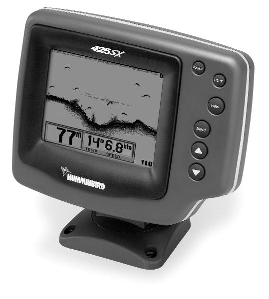
2 THANK YOU THANK YOU FOR CHOOSING YOUR 425SX FISHFINDER, MADE BY TECHSONIC INDUSTRIES, MANUFACTURER OF AMERICA S #1 NAME IN FISHFINDERS, HUMMINBIRD. HUMMINBIRD HAS BUILT ITS REPUTATION BY DESIGNING AND MANUFACTURING TOP QUALITY, THOROUGHLY RELIABLE MARINE EQUIPMENT. YOUR HUMMINBIRD PRODUCT IS DESIGNED FOR TROUBLE-FREE USE IN EVEN THE HARSHEST MARINE ENVIRONMENT. IN THE UNLIKELY EVENT THAT YOUR HUMMINBIRD DOES REQUIRE REPAIRS, WE OFFER AN EXCLUSIVE SERVICE GUARANTEE. COMPLETE DETAILS ARE INCLUDED AT THE END OF THIS MANUAL. WE ENCOURAGE YOU TO READ THIS OPERATIONS MANUAL CAREFULLY IN ORDER TO GET FULL BENEFIT FROM ALL THE FEATURES AND USES OF YOUR HUMMINBIRD PRODUCT. WARNING! THIS DEVICE SHOULD NOT BE USED AS A NAVIGATIONAL AID TO PREVENT COLLISION, GROUNDING, BOAT DAMAGE, OR PERSONAL INJURY. WHEN THE BOAT IS MOVING, WATER DEPTH MAY CHANGE TOO QUICKLY TO ALLOW TIME FOR YOU TO REACT. ALWAYS OPERATE THE BOAT AT VERY SLOW SPEEDS IF YOU SUSPECT SHALLOW WATER OR SUBMERGED OBJECTS.
3 TABLE OF CONTENTS Section 1: Installation preparation Parts Supplied Accessories Installation Overview Alternative Transducers and Mounting Methods Beginning Installation Section 2: How Sonar Works Simulator Operation What You See On Screen Control Functions Menu Functions Section 3: ADVANCED FEATURES Using Diagnostic Section 5: MAINTENANCE Maintenance and Troubleshooting Specifications
4 INSTALLATION PREPARATION PARTS SUPPLIED PARTS SUPPLIED Before installing your 425SX, please ensure the following parts are included in the box: 425SX fishfinder Transducer with 6m (20') of cable and mounting hardware kit Mounting system and mounting hardware kit 2m (6' ) power cable Publications kit Note: The 425SX + includes speed and temperature sensors with appropriate hardware and instructions for installation. If any of these items are missing contact your local dealer. ACCESSORIES Humminbird offers a wide assortment of accessories that complement and expand the capability of your new 425SX. These accessories are designed with the same high standards. The Humminbird Accessory catalog included with your unit contains descriptions of the many accessories available and ordering information. All Humminbird accessories are available through your full-service Humminbird dealer. INSTALLATION OVERVIEW The 425SX consists of two primary components to install: the control head and the transducer. The control head contains the sonar transmit and receive circuitry, as well as the user controls and display. It should be installed in a location that provides access to the controls and visibility while in use. The control head mounts on a quick disconnect mounting system that swivels and tilts, providing flexibility for viewing from almost anywhere on the boat. 2
5 INSTALLATION PREPARATION INSTALLATION OVERVIEW The transducer converts electrical energy from the transmitter into mechanical pulses or sound waves. The transducer also receives the reflected sound waves and converts them back into electrical signals for display on the control head. It should be installed in contact with the surface of the water in an area that has smooth water flow - usually on the transom of the boat. There are several mounting options for the transducer. Review the following section to determine the method that works for you and your boat. Determining How to Mount the Transducer The 425SX includes a model XT-6-24 transducer. This transducer can be mounted on the transom of the boat, or bonded to the inside of a fiberglass hull boat. The transom installation, which is the most widely used, places the transducer on the outside of the boat hull. This technique Transom Mounted Transducer produces the least signal loss, and provides a way to adjust the transducer after installation. The mounting hardware included is designed to protect both the boat and the transducer should the boat strike debris in the water or when trailering. Inside the Hull Mounted Transducer As an alternative to transom mounting, it is possible on many fiberglass-hulled boats to glue the transducer on the inside of the boat hull. Since fiberglass has similar sonar characteristics as water, the sonar signal can pass through the boat hull with minimal loss. The hull of the boat must be single layer construction (not double-hulled). Also, any air trapped in the lamination of the fiberglass would prevent the sonar 3
6 INSTALLATION PREPARATION ALTERNATE TRANSDUCERS AND MOUNTING METHODS signal from passing through. Inside the hull installations require no holes to be drilled into the boat and through experimentation, high-speed operation comparable to transom mounting can be achieved. Two part, slow cure epoxy is required to glue the transducer in place. ALTERNATE TRANSDUCERS AND MOUNTING METHODS The 425SX comes with everything necessary for installation and operation on most boats. However, there are several situations which may require a different type of transducer. Inboard boats, wood or metal hulls, and sail boats create unique transducer mounting needs. Alternate transducers and mounting methods are detailed below. Portable Mounting The standard transducer can be adapted for portable installations using part number MHX-PT2. This accessory adapts your transducer to a suction cup mount for temporary installation on the boat hull or other surface. Trolling Motor Mounting The standard transducer can also be adapted to mount on most trolling motors using part number AD-STM-7. This accessory includes a bracket and hose clamp that allows mounting the transducer to the body of most trolling motors. TRANSDUCER EXCHANGE 4 Other transducers are available as replacements for the standard transducer. You may exchange your new and unassembled transducer for another type by returning it to the address listed in Customer Support. Some transducers may have additional costs. Refer to the Accessory catalog or call Customer Support for information.
7 INSTALLATION PREPARATION BEGINNING INSTALLATION BEGINNING INSTALLATION Now that you have determined the transducer mounting method, you can begin installation of the 425SX. The fold out installation guide included provides detailed step by step instructions for installation of the control head and transducer. For transom mount transducer installations, you will need the mounting template at the back of this manual. In addition to the parts included you need the following for installation and operation: A powered hand drill and various drill bits Phillips and flat-head screw drivers A ruler or measuring tape Pen or pencil 12 volt power source (your boat s battery) A 1-amp fuse A fuse holder (if you are wiring directly to the boat s battery) Silicone sealant (for sealing drilled holes) 2-part, slow-cure epoxy (for inside the hull transducer installations) Note: If you have purchased the 425SX + you will have in addition to the parts and instructions above: Speed and Temperature sensors Instructions for installing speed and temperature sensors Appropriate hardware to mount sensors 5
8 HOW SONAR WORKS HOW SONAR WORKS Your Humminbird unit uses sonar to locate and define underwater objects, define the bottom terrain, as well as determine distance. Sonar technology is based on sound waves. Your Humminbird unit sends out a sound wave signal. With this signal it determines distance by measuring the time between the transmission of the sound wave and when the sound wave is reflected off an object. Your Humminbird uses the reflected signal to interpret location, size and composition of an object. Sonar is very fast. A sound wave can travel from the surface to a depth of 70m (240') and back again in less than ¹ ₄ of a second. It is unlikely that your boat can "outrun" this sonar signal. The 425SX is a 200 khz, single-beam fishfinder. The 200 khz frequency provides excellent sonar resolution (the ability to distinguish small returns or returns which are close to the bottom), while providing depth capabilities to 185m (600 ). The shape of the sonar beam is symmetrical and covers an area of approximately 24 degrees side to side and front to rear. Actual depth capability depends on factors such as bottom hardness, water conditions, and transducer installation. Units will typically read to deeper depths in fresh water than in salt water. SIMULATOR OPERATION The 425SX contains a simulator that allows you to use the unit as if you are on the water. The simulator is invaluable for learning how to operate the 425SX. There are two ways to start the simulator. If the unit is powered off, press and hold the POWER button for approximately three seconds until you hear a continuous chirp. 6
9 SIMULATOR OPERATION The simulator can also be started by selecting the Simulator option on the start-up screen after you power-up the unit. When this screen is shown, simply press the DOWN ARROW until Simulator is highlighted. When the screen times out, the unit will be in simulator mode. When in simulator operation, the 425SX responds to control inputs as if it is in actual operation, so feel free to experiment, or to customize the unit for your particular operation. To exit Simulator mode, power the unit off. FEATURE MEMORY If your 425SX is installed with a transducer connected, any changes you make to the set-up or User Options (see Control Functions) while in Simulator are retained in the unit s memory. This allows you to use simulator to experiment with the various set-up options, and retain your selected settings for normal operation. If you are using the 425SX in Simulator when no transducer is connected, any selected options are lost when the unit is powered off. The 425SX will return to Factory Settings, or options selected when last used with a transducer, if no transducer is connected. IMPORTANT: A transducer must be connected to the 425SX in order to retain user settings selected when in simulator mode. If no transducer is detected, the unit defaults to pre-selected options when powered off. What You See On-Screen Your 425SX uses a 160 x 160 matrix FSTN LCD display. This display provides outstanding viewability in all light conditions over a wide range of temperatures. 7
10 WHAT YOU SEE ON-SCREEN At initial power-up, the 425SX uses settings that were set at the factory. After initial use, the 425SX will remember the settings you enter. There are several elements on-screen that are common to all modes of operation. Figure A Temperature/Speed. The initial screen layout takes one of two basic forms depending on whether the optional Temp/Speed accessory is installed. Figure A shows the default view when the Temp/Speed accessory is installed. Figure B shows the default view when the Temp/Speed accessory is not 6 installed. Depth. The digital depth number shows the water depth directly beneath the transducer location. Depth Range. The depth range is shown to the right of the screen. The upper number is 0 indicating the surface of the water. The lower number is one of the nine depth ranges available that best match the depth of the water. As the depth of the water changes, the range changes as necessary in order to retain a bottom representation on-screen. Water Depth Bottom Depiction Figure B Zero Line Depth Range 8
11 WHAT YOU SEE ON-SCREEN When in Auto mode, the horizontal line at the top of the screen is the zero line, representing the surface of the water. Occasionally there is a gap in this line. This gap indicates the unit is updating the display even if the bottom is not visible on-screen, or if the bottom information is not changing. New sonar information appears on the right side of the graphic area of the display and moves to the left as new information is displayed. The 425SX automatically selects the appropriate depth range to show the depth of water beneath the transducer. This range is selected so the bottom representation is typically shown about ² ₃ down the display. Bottom. The graphic depiction of the bottom provides the user with an effective tool for understanding the composition of the bottom. The FSTN type display uses 4 discrete levels of gray to indicate the intensity of the returned sonar signal. The 425SX can display even the smallest sonar returns with light gray pixels. Larger returns are displayed with darker shades of gray. If the bottom is hard and smooth, the bottom depiction is narrow and dense. If the bottom is soft mud or sand, the depiction will be thick and less dense. This indicates that much of the signal is absorbed by the soft bottom. If the bottom is rocky or rugged in composition, the depiction is of varying density and textured in appearance. Wave action also affects the bottom depiction. The information drawn is a distance measurement, so if the boat is moving up and down over flat bottom, the bottom depiction often appears in regular variations that match wave timing. Structure. Structure is defined as any object physically attached to the bottom. The sonar configuration of the 425SX is optimized to give the most accurate depiction of bottom structure possible. Grass, trees, stumps, wrecks or other debris are accurately displayed, however the Surface Clutter m Hard Bottom Soft Bottom Rocky Bottom 9

12 WHAT YOU SEE ON SCREEN depiction of these objects varies with boat speed and direction. The best way to learn to interpret structure is to operate the 425SX over a variety of known conditions and experiment with user functions to best represent those conditions on-screen. Surface Clutter. Surface clutter is the layer of water near the surface that is rich in algae and other growth, and often is aerated by wind or wave action. This area of water interferes with sonar transmission and often appears on-screen as regular clusters of individual dots near the 0 line. Thermoclines. Thermoclines are sharp differences in water temperature. These are easily identified by the continuous nature of the return. Second Returns. When a sonar signal is reflected off the bottom back to the transducer, there is often enough energy left in the signal to be reflected off the surface of the water back to the bottom a second time. Second returns appear as a slightly weaker bottom representation exactly twice the depth of the primary bottom return. The second return is most likely to occur in shallow water and in areas of relatively hard bottom. Thermocline Second Return Fish Arches. With Fish ID off, schools of bait fish as well as individual fish are clearly visible on the 425SX display. Bait fish appear as "clouds" having different shapes and sizes depending on the number of fish and boat speed. Individual fish appear as smaller black and gray lines often appearing as a "fish arch." A fish arch forms as the boat moves over the fish. Due to the transducer beam angle the distance to the fish decreases as it moves into the beam, and then increases as it moves out. When the window graphs this distance change, an arch appears. The true depth of the fish is the top of the arch when the boat is directly over the fish. Boat 10
13 WHAT YOU SEE ON SCREEN speed and movement of the fish greatly affect the shape of the arch. When moving slowly, a fish creates an elongated arch. With the boat moving fast the arch appears shorter. A partial arch forms when the fish does not move through the entire cone angle. Fish Arch Diagram The 425SX displays structure such as submerged grass, brush, trees and wrecks on the bottom. Structure can be distinguished by comparing the area just above and below the main bottom return. Usually structure shows as areas of dark to light gray on top of a dark bottom contour. The appearance of structure is greatly affected by boat speed and direction; to repeat the same image it is often necessary to travel the same speed and direction over the location where the structure was originally located. The 425SX is also capable of showing layers of water having different temperatures. These temperature differences, called thermoclines, appear at different depths, depending on current conditions. A thermocline typically appears as a continuous band of light gray moving across the display at the same depth. Thermoclines always appear above the bottom. It is important to remember that sonar cannot distinguish between a fish and some other object suspended in the water. Regardless of the object the sonar detects, each could be drawn as an arch. Fish ID. The 425SX uses advanced signal processing to further evaluate any sonar return between the surface and the bottom. For instance, a small school of bait fish usually appears as a dense cluster of individual dots. If the return meets certain additional criteria, a fish symbol will be assigned. There are three different size fish symbols used to indicate ID+ Fish Depth 11
14 CONTROL FUNCTIONS the intensity of the sonar return. While signal intensity is a good indicator of relative fish size, different species of fish have different sonar characteristics, so it is not always possible to distinguish fish size between varying species. The signal intensity is "normalized" for depth so that a small fish close to the boat does not appear as a large fish symbol. ID+ adds an additional piece of information to help the user locate fish. On selected fish symbols, the digital depth of the designated fish is drawn to help locate the fish vertically. This is especially helpful in setting bait depths or for downrigger operation. CONTROL FUNCTIONS The 425SX uses a simple six button keypad for all user input. Press any button and an audible chirp confirms the control input. If a button has no function or is inappropriate for the situation, an audible error is heard. The unit sounds multiple chirps. Power. The Power button powers the 425SX up for normal operation. When the unit is on, POWER turns the unit off. POWER can also be used to go directly into Simulator mode. To enter simulator, with the unit powered off, press and hold POWER for several seconds until a continuous chirp is heard. Light. LIGHT controls the unit s display backlight. With the unit powered on, press LIGHT once to turn the backlight on low. Press LIGHT a second time to turn the backlight on medium, a third time to turn the backlight on high, and a fourth time to turn the backlight off. The backlight is very effective for low-light and nighttime operation. When the backlight is on, the 425SX will consume more power than with the backlight off. This is important when using the 425SX in a portable configuration powered by a separate battery, or when powering the unit from a trolling motor battery. 12
15 CONTROL FUNCTIONS When powering the unit from a battery such as in portable applications, you can prolong the battery life by using the backlight at a minimum. The three lower buttons, MENU, UP ARROW and DOWN ARROW work together to control the 425SX menu-controlled user functions. 2D View View. VIEW selects one of several screen configurations or views possible depending on the transducer in use. When using the standard transducer, without the optional speed/temp sensor connected, the VIEW button toggles the display between the full-screen 2D View and the Large Digital Readout View. 6 The 2D View is the default view, and the view which is first seen at power-up. Pressing VIEW again will select the Large Digital Readout View, which increases the size of key digital information so that it can be viewed from a great distance. Normal 2D information is displayed on the right side of the display. Pressing VIEW again will toggle the display back to the 2D view. Large Digit View When using the standard transducer, with the optional speed/temp sensor connected, the VIEW button toggles the display between the full-screen 2D View, the Chart View and the Large Digital Readout View. 13

16 CONTROL FUNCTIONS The Chart View, shows only the digital depth readout, leaving more screen area for fish location and bottom depiction. Menu. MENU displays a menu on-screen for adjustment. In normal operation, pressing MENU repeatedly cycles through all available menus. A menu remains on-screen for several seconds, and can be adjusted by using the ARROW keys. If no adjustment is made in the allotted time, the menu disappears. If you want the menu to remain on-screen longer press and hold MENU the menu will remain on-screen indefinitely. Once you release the menu button, the screen will time out. Once a menu times out, it is still considered the active menu. Press MENU to bring up the last menu used. Menu Chart View Arrow Keys. The UP ARROW and DOWN ARROW make adjustments to menu functions. On the left side of every menu there are UP ARROW and DOWN ARROW symbols. The symbols indicate which ARROW button has a function in a particular situation. Either one or both ARROW buttons can be used to adjust the menu function. A hollow ARROW symbol means the corresponding ARROW button has no function. Pressing that button will result in no adjustment and the error audible will be heard. A solid ARROW symbol means the corresponding ARROW button can be used to affect the menu adjustment. Abbreviated Menu. The ARROW buttons often can be used when no menu is on-screen. In these situations, pressing the ARROW button affects the function of the active (last-used) menu. This is a short-cut to menu Abbreviated Menu operation. An abbreviated menu appears on-screen while the adjustment is made and times out. A frequently used menu can be adjusted very quickly using this technique. 14
17 MENU FUNCTIONS After an adjustment is made to a menu function, the menu times out after a few seconds and the unit returns to normal operation. Menu Layout. All menus use the same basic layout. The heading at the top describes the menu function. The UP ARROW and DOWN ARROW symbols to the left of the menu indicate which buttons are available for adjustment. In menus that have several possible settings, a range of adjustment indicator shows the total range available and the current setting. Within the menu are the options available. The selected option or current setting is highlighted in the black box. If no adjustment is made, this is the selected setting. Press an ARROW button while the menu is displayed to select another option. Several of the menus are multi-step. In some situations if an adjustment is made, additional options become available for further adjustment. Examples of these multi-step menus are Depth Range, Depth Alarm and Zoom. See the detailed description of each function for further explanation. Menu Functions Heading Up Arrow Option Down Arrow Option Arrow Symbols Selected Setting Range of Adjustment Indicator Sensitivity. The Sensitivity function controls the sensitivity of the sonar receiver. The 425SX automatically adjusts the level of receiver sensitivity based on a number of factors including the depth of the water and the level of noise present. Noise can be caused by other electronic devices, engines, trolling motors, propeller cavitation and hydrodynamic flow among others. 15
 has no effect on the automatic sensitivity control.")
18 MENU FUNCTIONS The user has the option of adjusting the Sensitivity higher or lower based on personal preference. You can select one of 11 sensitivity settings from - 5 to +5. A setting of 0 (factory setting) has no effect on the automatic sensitivity control. Increasing the sensitivity (+1 through +5) enables the unit to display the information from progressively smaller sonar returns. By decreasing the sensitivity (-1 through -5), the unit effectively filters small sonar returns. High Sensitivity Sensitivity at 0 Low Sensitivity In murky or muddy water, it is often helpful to reduce the sensitivity. This prevents the display from being cluttered with sonar returns from debris or suspended particles. In very clear or very deep water, it may be helpful to increase the sensitivity since even the smallest sonar return may be of interest to the user. To adjust Sensitivity, press MENU repeatedly until the Sensitivity heading is displayed. When the Sensitivity menu appears, use the UP ARROW to increase the sensitivity, or the DOWN ARROW to reduce sensitivity. To sequence through the available settings, press and hold either ARROW button. Release the button at the setting you want to select. After an adjustment is made, the menu disappears and the new sensitivity setting is in affect. If additional time is needed to study a menu, press and hold the MENU button and the menu will remain on-screen indefinitely. If you need to make an additional adjustment, press the UP ARROW or DOWN ARROW button. Depth Range. The Depth Range function controls the vertical distance displayed on the graphic area of the display. There are nine depth ranges available. The top of the range is always 0, or the surface of the water. Ranges of 0 5, 0 10, 0 20, 0 40, 0 60, 0 80, 0 110, 0 150, and metres and imperial ranges of 0 15', 0 30', 0 60', 0 120', 0 180', 0 240', 0 360', 0 480', and 0 600'. 16
19 MENU FUNCTIONS The range that positions the bottom depiction closest to the bottom of the screen, will best utilize the available display resolution. Using the factory setting of AUTO the 425SX can automatically adjust the depth range depending on the depth of the water. The unit tries to maintain the bottom depiction about ² ₃ down the total range (for example, in 6 m (20') of water, the 0-10m (0-30') range would be selected). This provides the best display resolution and therefore the best target separation possible. The Depth Range can be adjusted manually. Press MENU repeatedly until the Depth Range menu is visible. Two options are available: Auto and Manual. The manual setting enables you to adjust the current depth range setting. The unit no longer adjusts the Depth Range to the most appropriate range for bottom display. Often, the bottom may not be visible on-screen. The digital depth readout always determines the depth of the bottom, even if it is not visible on-screen. Using manual Depth Range control, you can view sonar information from the area near the surface in greater detail. To return to automatic Depth Range control, press the MENU button until the Depth Range menu appears onscreen and use the UP ARROW to select AUTO. Depth Range 6 17
20 MENU FUNCTIONS Zoom. The 425SX uses a greatly enhanced Zoom capability called TruZoom which offers expanded information on a select area of sonar information. Zoom is similar to Depth Range because it controls the range of information displayed on screen. Zoom, however, allows for selection of ranges beneath the surface so any area of water between the surface and the bottom can be enlarged to provide more detailed information. By using the full display to show a small area of coverage, the effective display resolution is increased, and the unit s ability to separate close targets is enhanced. The Zoom ranges available are dependent on the current depth range. In the 5m (15') depth range, TruZoom displays a range equal to one half the current depth range. In the 10m (30'), 20m (60'), 40m (120'), 60m (180'), 80m (240'), 110m (360'), 150m (480') and 185m (600') depth ranges, TruZoom displays a range equal to one fourth the current depth range. The box at the right side of the screen outlines the area to be zoomed. The 425SX shows Zoom range in conjunction with the full depth range. The Zoom range is shown on the left side of the screen and full range information is shown on the right side of the display. The area which is being enlarged by Zoom is indicated by the square box. Zoom can either operate automatically, in which the Zoom range is constantly adjusted to show the bottom, or manually, in which the user controls the location of the Zoom range. Automatic Zoom is especially helpful when looking for structure or bottom detail. The Automatic Zoom keeps the bottom in view even in quickly changing terrain. Manual Zoom provides detailed information of any area from the surface to the bottom. 18
21 MENU FUNCTIONS In Manual Zoom, the Zoom Upper Zoom Limit range does not move as the terrain changes. To operate Zoom, press MENU repeatedly until the Zoom menu is onscreen. Three options are available: Off (Factory Setting), Auto (Automatic bottom tracking Zoom), and Manual (User controlled Zoom range). Press the DOWN ARROW once to highlight Auto or twice to highlight Manual. If Manual is selected a submenu will appear Lower Zoom Limit allowing manual zoom range adjustment. When the menu disappears, full range information is displayed on the right as always. The square box indicates the Zoom range. In Auto Zoom, the box will move vertically to remain in the general area of the bottom return. The left side of the screen is a magnified view of the information seen inside the Zoom range box. The upper and lower depth limits of the Zoom range are shown on the right side of the Zoom view. Note: It is not possible to use Zoom in conjunction with the Large Digital View. To disable Zoom, press the MENU button until the Zoom menu is on-screen. Use the UP ARROW to highlight Off, and let the menu time out. When the unit is powered off, the Zoom menu returns to Zoom Off. Depth Alarm. The 425SX contains an audible alarm to warn you of shallow water depths. The alarm is adjustable to depths of.6m (2') to 30m (99'). When the alarm is enabled, an audible alarm sounds if the water beneath the boat is equal to or less than the selected alarm depth. The alarm sounds continuously for about five seconds, and 19
22 MENU FUNCTIONS then intermittently to remind you that you are still in shallow water. Additionally, the 425SX can anticipate quickly changing terrain and sound the Depth Alarm before the bottom depth actually reaches the preset alarm depth. Fish Alarm. The Fish Alarm alerts you to the presence of fish, or other targets not connected to the bottom. The Fish Alarm has three different settings that correspond to the three different size fish symbols shown on-screen. The default setting is OFF. With the Large fish only setting, the 425SX alarms on only those targets that are represented by the large fish symbols. The 425SX can be set to alarm on only large and medium fish, or set to alarm on all fish. Once the Fish Alarm is enabled, the 425SX emits an audible beep when the selected size fish symbol appears on-screen. The sound is slightly different for each of the three fish symbol sizes, so with practice, it is possible to distinguish the size of the detected fish without looking at the unit. Fish Alarm settings are remembered when the unit is powered off. Triplog. Triplog provides a running log of information based on input from the Temp/Speed sensor. Since Triplog requires information from the Temp/Speed sensor to operate, if this sensor is not detected by the 425SX, the Triplog menu will not appear as an option. 20

23 MENU FUNCTIONS Triplog provides four pieces of information: the total time elapsed since power-up or reset, the distance traveled since the 425SX was powered up or reset, the average speed, and the input voltage from your boat s electrical system. The time, speed and distance calculations are useful for tracking your progress on a Triplog trip. The input voltage is useful for determining the condition of the charging system of the boat. When used in a portable application or whenever the 425SX is operated from a battery source, the voltage number can be used to determine battery life. The 425SX will operate at voltages from 10 to 20 VDC. Voltages in excess of 20 or less than 10 VDC cause the unit to power off. The Triplog resets at power off. Options. The Options Menu is a series of linked menu functions used initially to set your preferences. Once your preferences are selected, it is unlikely these functions need to be accessed during the normal operation of the product. The Option menus include: Contrast, Display Speed, Battery Alarm, Bottom Black, Fish ID, Numeral size, Units Speed, Units Depth, Language, Speed Offset, Depth Offset and Reset. Press the view key at any time to exit options and return to normal operation. Languages. The language menu displays available language choices. Included in the 425SX are: ENGLISH, FRENCH, ITALIAN, GERMAN, NORWEGIAN, SWEDISH, SPANISH, FINNISH, PORTUGUESE, POLISH, DANISH, HUNGARIAN AND DUTCH. To select your language, push the UP or Down Arrow Buttons to scroll through the list. 21
24 MENU FUNCTIONS Contrast. The Contrast function allows the user to control the level of contrast of the LCD display. The 425SX will automatically adjust the display contrast to compensate for changing ambient temperatures; however, some situations may occur where manual adjustment will provide a higher level of contrast. Eleven contrast settings, +5 to -5, are possible. The display contrast will change as the adjustment is made so the optimum level of contrast can easily be adjusted. Use the ARROW buttons to highlight the desired selection. Display Speed. Display Speed controls the rate at which the graphic information moves across the display. There are 5 possible speeds; the fastest rate (5) is the factory setting. If your boat is stationary or moving very slowly for extended periods, it may be desirable to update the display at a slower rate. The closer the update rate matches boat speed, the more accurate is the graphic depiction of the terrain beneath your boat. Use the UP and DOWN ARROWS to select the desired update rate. (1) is the slowest, (5) is the fastest. Use the MENU button to advance to the next menu. The Display Speed setting is remembered when the unit is powered off. Battery Alarm. The Battery Alarm Option allows you to select the voltage level at which the Battery Alarm activates. At the Battery Alarm menu (under options), you will note that the default setting is OFF. Push the DOWN ARROW BUTTON to select the feature ON. Push the DOWN ARROW BUTTON again to move into the ADJUST BATTERY ALARM setting. Using the UP and DOWN ARROW BUTTONS, select a voltage between 9.0 and

25 MENU FUNCTIONS When the voltage drops below your selected voltage, an audible alarm will sound, and a battery alarm icon will be displayed on screen with current voltage level. Bottom Black. There are two selections available: Off and On. The factory setting is Off. With this setting, the 425SX displays the bottom using 4 level grayscale. This allows you to determine the texture and relative hardness of the bottom. Selecting Bottom Black ON causes the unit to blacken in the display below the bottom. This gives the user easiest recognition of the bottom location, even from a great distance. The 425SX remembers the Bottom Black setting when powered off. Fish ID. There are three selections available: Off, ID+ ON, and Adjust. The factory setting is ID+ OFF. With Fish ID Off, sonar returns are displayed as raw information. There is no interpretation made by the unit. Selecting ID ON also enables the fish alarm. Bottom Black View ID+ On Raw Sonar ID+ On enables the 425SX to interpret the raw sonar data and, using a variety of techniques, depict appropriate target returns as one of three different size fish symbols. Further identification shows which beam the fish is detected in. The 425SX also displays the depth beneath the surface with the corresponding fish symbol. 23
26 MENU FUNCTIONS Selecting Adjust and making incremental changes enhances the fishfinder s ability to identify sonar returns as fish symbols. Increasing the value to a number greater than zero shows more fish symbols on-screen. In this case smaller sonar returns will be depicted as fish symbols. This is useful for identifying many smaller sonar returns (such as bait fish) as fish symbols. Decreasing the value to a number less than zero shows fewer fish symbols onscreen. In this case smaller sonar returns are disregarded. This is useful for eliminating many small sonar returns when seeking larger species of fish. The 425SX remembers this selection even when the unit is powered off. Numeral Size. Two options are available: Big and Small. The factory setting is Big. With this setting, the digital depth and speed and temp numerals are drawn large enough to be read from across the boat. The big numerals occupy space on the display that could be used for the graphics area. Hence, the small numerals option. With small numerals selected, a greater amount of the display area is available for the graphic view. This effectively increases the display resolution of the unit. Numeral Size settings are remembered when powered off. Units Speed. Units of Speed allows the selection of MPH (statute miles per hour), KTS (nautical miles per hour) or KPH (Kilometers Per Hour). Use the Arrow buttons to highlight the desired selection. Speed Offset. The Speed Offset option allows the user to compensate for differences in hull design, and its effect on the accuracy of the speed measurement. If there is a discrepancy between the indicated speed and another speed measurement device on the boat, the speed measurement can be varied to improve 24
27 ADVANCED FEATURES USING DIAGNOSTIC accuracy. Remember, the speed paddle wheel measures speed through the water, not speed over ground. Speed offset is remembered after power is disconnected. Depth Offset. The Depth Offset allows the user to select the point on the boat from which the depth measurement is made. Selecting a positive value adds distance to the measurement. If the transducer is mounted 1 metre beneath the waterline, a positive 1 will show the correct depth from the surface of the water. Another frequent use of depth offset is to show the depth beneath the deepest point of the hull. A negative value equal to the distance from the transducer location and the deepest point of the hull will have the same effect as mounting the transducer at the deepest point. Depth offset is remembered after power is disconnected. Reset. With the many User Options available to customize the 425SX, it is easy to configure the unit in such a way that it is detrimental to a particular use. By using the Reset function, all variable or user-controlled features of the 425SX are returned to the factory settings. The Reset function is an important first step in troubleshooting problems to ensure that a user selected setting is not the cause for the perceived problem. USING THE DIAGNOSTIC FEATURE The 425SX contains a powerful diagnostic tool that can aid in determining the cause of a problem. To use the Diagnostic feature, select the Diagnostic feature on the start-up menu of the initial screen. 25
28 ADVANCED FEATURES USING DIAGNOSTIC Self Test. Initially, the 425SX will perform a self-test. This test confirms the operation of all internal circuitry. At the conclusion of the test, one of two messages will appear. PASSED indicates the internal test discovered no failures, FAILED indicates a significant internal problem was discovered and the unit requires factory service. A code number appears that tells repair personnel where the problem is. Transducer Connection. The first connection tested is Transducer input. If a transducer is detected, the message CONNECTED appears. If a series of dashed lines is shown, no transducer is connected or there is a problem with the transducer or cable. If you are using multiple transducers, switch between transducers to confirm the connections for each. Voltage Input. Another connection tested is the voltage input, and is especially helpful in diagnosing input voltage problems. The current input voltage is displayed. If voltage fluctuations or power supply in excess of 20 VDC or less than 10 VDC is suspected, use the diagnostic screen to confirm input voltage. Often, small outboard motors do not effectively regulate voltage when operated at high engine speeds. Use Diagnostic while running the boat at high speeds to show the voltage gain. Also, if you are using the 425SX in portable configuration or from the trolling motor battery, Diagnostic can be used to evaluate the health of the battery by showing the present voltage. Total Time. The total time category indicates the total time the unit has been in use since shipped from the factory. It is normal for some hours to appear in the total time when the unit is new due to factory testing. While this is often of interest to the user, it is primarily a diagnostic tool for the repair technician should the unit need service. 26
29 ADVANCED FEATURES MAINTENANCE/TROUBLESHOOTING MAINTENANCE Your 425SX is designed to provide years of trouble free operation with virtually no maintenance. Follow these simple procedures to ensure your 425SX continues to deliver top performance. If the unit comes into contact with salt spray, simply wipe the affected surfaces with a cloth dampened in fresh water. Do not use a chemical glass cleaner on the lens. Chemicals in the solution may cause cracking in the lens of the unit. When cleaning the LCD protective lens, use a chamois and non-abrasive, mild cleaner. Do not wipe while dirt or grease is on the lens. Be careful to avoid scratching the lens. If your boat remains in the water for long periods of time, algae and other marine growth can reduce the effectiveness of the transducer. Periodically clean the face of the transducer with liquid detergent. Pivoting the transducer up in the bracket may allow better access for inspection or cleaning. If your boat remains out of the water for a long period of time, it may take some time to wet the transducer when returned to the water. Small air bubbles can cling to the surface of the transducer and interfere with proper operation. These bubbles dissipate with time, or you can wipe the face of the transducer with your fingers after the transducer is in the water. Never leave the 425SX in a closed car or trunk the extremely high temperatures generated in hot weather can damage the electronics. TROUBLESHOOTING Do not attempt to repair the 425SX yourself. There are no user serviceable parts inside, and special tools and techniques are required for reassembly to ensure the waterproof integrity of the housing. Repairs should be performed only by authorized Humminbird technicians. Many requests for repair received by Humminbird involve units that do not actually need repair. These units are returned no problem found. If you have a problem with your 425SX, use the following troubleshooting guide before calling your dealer or sending your unit in for repair. The 425SX contains several tools that can aid in determining if there is a problem and how to isolate and repair the problem in many cases. 27
30 ADVANCED FEATURES TROUBLESHOOTING 1. Nothing happens when I turn the unit on. Check the power cable connection at both ends. Be sure the cable is connected correctly to a reliable power source red lead to positive, black lead to negative or ground. Ensure the power available at the mount is between 10 and 20 VDC. If the unit is wired through a fuse panel, ensure the panel is powered. Often accessory fuse panels are controlled by a separate switch or the ignition switch. Also, often a fuse can appear to be good when in fact is not. Check the fuse with a tester or replace it with a fuse known to be good. Check the power connection to the 425SX. It is possible to force the power cable connector into the cable holder incorrectly. If the connector is reversed, the unit will not work. Examine the contacts on the back of the unit to ensure there is no corrosion. Finally, ensure the unit is firmly seated on the mount. The electrical contacts are not made until the unit is fully seated. Ensure the metal cable retainer is properly installed in the mount. If not, the power connection may push out when the unit is put on the mount. 2. There is no transducer detected. The 425SX has the ability to detect and identify that a transducer is connected. First, ensure that an appropriate transducer connector is positioned correctly in the connector holder, and that the unit is fully seated on the mount. Second, inspect the transducer cable from end to end for breaks, kinks, or cuts in the outer casing of the cable. Also ensure the transducer is fully submerged in water. If the transducer is connected to the unit through a switch, temporarily connect it directly to the unit and try again. If none of these items identifies an obvious problem, the transducer itself is probably the problem. Be sure to include the transducer if returning the unit for repair There is no bottom reading visible on the display. There are a number of possible causes for this condition. If the loss of bottom information occurs only at high boat speeds, the transducer needs adjusting. If the digital depth readout is working but there is no bottom visible on-screen, it is possible the depth range has been adjusted manually to a range lower than what is needed to display the bottom. Also, in very deep water, it may be necessary to manually increase the sensitivity setting to maintain a graphic depiction of the bottom.
31 ADVANCED FEATURES TROUBLESHOOTING If you are using a transducer switch to connect two transducers to the 425SX, ensure the switch is in the correct position to connect a transducer that is in water. (If a trolling motor transducer is selected and the trolling motor is out of water, no sonar information appears.) If none of the above solve the problem, inspect the transducer cable from end to end for breaks, kinks, or cuts in the outer casing of the cable. If the transducer is connected to the unit through a switch, temporarily connect it directly to the unit and try again. If none of these items identifies an obvious problem, the transducer itself may be the problem. Be sure to include the transducer if returning the unit for repair. 4. When in very shallow water, I get gaps in the bottom reading and inconsistent digital depth indication. The 425SX will work reliably in water.6m (2') or deeper. The depth is measured from the transducer, not necessarily from the surface. 5. The unit comes on before I press POWER, and won t turn off. Check the transducer cable if the outer jacket of the cable has been cut and the cable is in contact with bare metal, you need to repair the cut with electrical tape. If there is no problem with the cable, disconnect the transducer from the unit and see if the problem is corrected, to confirm the source of the problem. 6. I get gaps in the reading at high speeds. Your transducer needs adjusting. If the transducer is transom-mounted, there are two adjustments available to you height, and running angle. Make small adjustments and run the boat at high speeds to determine the effect. It may take several tries to optimize high speed operation. This can also be a result of air or turbulence in the transducer location caused by rivets, ribs, etc. 29
32 ADVANCED FEATURES TROUBLESHOOTING 7. My unit loses power at high speeds. Your 425SX has over-voltage protection that turns the unit off when input voltage exceeds 20 VDC. Some outboard motors do not effectively regulate the power output of the engine s alternator and can produce voltage in excess of 20 volts when running at high RPMs. The 425SX displays input voltage in the Diagnostic screen. Use this readout to determine if the voltage exceeds 20 VDC. 8. The screen begins to fade out. Images are not as sharp as normal. Check the input voltage using Diagnostic. The 425SX will not operate on input voltages below 10 VDC. 9. The display shows many black dots at high speeds and high sensitivity settings. You are seeing noise or interference caused by one of several sources. Noise can be caused by other electronic devices. Turn off any nearby electronics and see if the problem goes away. Noise can also be caused by the engine. If engine noise is causing the interference, the problem will intensify at higher RPMs. Increase the engine speed with the boat stationary to isolate this cause. Propeller cavitation can appear as noise on-screen. If the transducer is mounted too close to the propeller, the turbulence generated can interfere with the sonar signal. Ensure that the transducer is mounted at least 38cm (15") from the prop. For Service and/or repair of your 425SX please contact your local dealer. Further information on HUMMINBIRD products can be found at: 30
33 SPECIFICATIONS Languages supported: Danish, Dutch, English, Finnish, French, German, Hungarian, Italian, Norwegian, Polish, Portuguese, Spanish and Swedish. Operating Frequency khz Power Output Watts (RMS) 3200 Watts (Peak to Peak) Area of Coverage at -10 db Power Requirement VDC Display FSTN LCD LCD Matrix in pixels H x 160 V Viewing Area cm H x 7.6cm V (4" H x 3" V) Mounting Quick Disconnect Mount Unit Size cm H x 20cm W x 11cm D (7⁵ ₈"H x 7⁷ ₈"W x 4³ ₈"D) Transducer (Standard) XT-6-24 Transducer Cable Length metres (20') Depth Ranges.... 5, 10, 20, 40, 60, 80, 110, 150 & 185 metres ', 30', 60', 120', 180', 240', 360', 480', & 600' Zoom Ranges , 5, 10, 15, 20, 28, 38 & 46 metres (7¹ ₂', 15', 30',45', 60', 90', 120', 150') 31
34
35 Use this template with transducer mounting bracket Remove and use for Transducer Installation TOP Use ⁵ ₃₂" (4.0mm) drill bit 19.3mm Drill Drill DO NOT LET DEADRISE INTERSECT THIS LINE PLACE EITHER CORNER ON DEADRISE ANGLE
36
PIRANHA I & 2 OPERATION GUIDE
 PIRANHA I & 2 OPERATION GUIDE Thank You Thank you for purchasing a Piranha fishfinder from Humminbird, America s #1 Manufacturer of quality consumer marine electronics WARNING! This device should not be
INSTALLATION PREPARATION
 PARTS SUPPLIED INSTALLATION PREPARATION PARTS SUPPLIED Before installing your new Humminbird fishfinder, please ensure the following parts are included in the box: Fishfinder Transducer with 20 (6m) of
INSTALLATION.. 6 Transom Installation... 6 Inside the Hull Installation. 10 Control Head Installation Test the Installation 15
 TABLE OF CONTENTS INSTALLATION PREPARATION 2 Parts Supplied. 2 Accessories. 2 Installation Overview.. 2 Alternative Transducers and Mounting Methods... 4 Transducer Exchange 5 INSTALLATION.. 6 Transom
PiranhaMAX & Fishin Buddy MAX
 PiranhaMAX & Fishin Buddy MAX Thank You! Thank you for choosing Humminbird, the #1 name in marine electronics. Humminbird has built its reputation by designing and manufacturing top-quality, thoroughly
500 Series Operations Manual _A
 500 Series Operations Manual 531521-1_A Thank You! Thank you for choosing Humminbird, America's #1 name in fishfinders. Humminbird has built its reputation by designing and manufacturing topquality, thoroughly
Operations Manual. Matrix 10 Matrix 27. Matrix 17 Matrix 37. offered by Busse-Yachtshop.de _A
 Operations Manual 531284-2_A Matrix 10 Matrix 27 Matrix 17 Matrix 37 Thank You! Thank you for choosing Humminbird, America's #1 name in fishfinders. Humminbird has built its reputation by designing and
141c Operations Manual _B
 141c Operations Manual 531442-1_B Thank You! Thank you for choosing Humminbird, America's #1 name in fishfinders. Humminbird has built its reputation by designing and manufacturing top-quality, thoroughly
PiranhaMAX & Fishin Buddy MAX _A
 PiranhaMAX & Fishin Buddy MAX 532419-3_A Thank You! Thank you for choosing Humminbird, the #1 name in marine electronics. Humminbird has built its reputation by designing and manufacturing top-quality,
_A - 747c_&_777c2_Man_Eng.qxp 10/2/2006 1:40 AM Page c and 777c 2 Operations Manual _A
 531526-1_A - 747c_&_777c2_Man_Eng.qxp 10/2/2006 1:40 AM Page 1 747c and 777c 2 Operations Manual 531526-1_A 531526-1_A - 747c_&_777c2_Man_Eng.qxp 10/2/2006 1:40 AM Page 2 Thank You! Thank you for choosing
FF718Li fish finder Cable transducer Mode Operations Manual
 I FF718Li Fish Finder Operations Manual FF718Li fish finder Cable transducer Mode Operations Manual 1.Thank you for choosing ~ FF718Li fish finder. The FF718Li is a combo unit that allows you to choose
Horizon Strike 200/220s
 Horizon Strike 200/220s Fishfinder Owner s Manual MARINE PRODUCTS LIMITED WARRANTY Standard Communications Corp. (SCC) warrants to the original consumer purchaser (the Purchaser) only that each new Marine
INSTALLING THE ECHO SOUNDER TRANSDUCER CHANGING THE OPERATING CONFIGURATION
 INTRODUCTION INSTALLING THE DISPLAY INSTALLING THE LOG PADDLE WHEEL UNIT INSTALLING THE ECHO SOUNDER TRANSDUCER NOTES ON ELECTRICAL INTERFERENCE USING THE INSTRUMENT SETTING THE MINIMUM DEPTH ALARM SETTING
DESIGNED AND MANUFACTURED IN ENGLAND CLIPPER DEPTH DEPTH METRES ECHO SOUNDER.
 DESIGNED AND MANUFACTURED IN ENGLAND CLIPPER DEPTH DEPTH 7 METRES ECHO SOUNDER INTRODUCTION 2 INSTALLING THE DISPLAY 2 INSTALLING THE TRANSDUCER 3 NOTES ON ELECTRICAL INTERFERENCE 5 GETTING STARTED 5 OPERATIONAL
TRANSDUCER RESOURCE GUIDE EN_A
 TRANSDUCER RESOURCE GUIDE 532651-1EN_A THANK YOU! Thank you for choosing Humminbird, the #1 name in marine electronics. Humminbird has built its reputation by designing and manufacturing top quality, thoroughly
FISH 4100 / Installation and Operation Manual. English... 3 Français Español Português
 FISH 4100 / 4150 Installation and Operation Manual English... 3 Français... 24 Español... 46 Português...68 www.navman.com FCC Statement Note: This equipment has been tested and found to comply with the
NAKI 600, 610, 620 Fishfinder
 www.goyachting.cn YTM-10600V2 TM NAKI 600, 610, 620 Fishfinder Installation and Operation Instructions All right reserved! Except as expressly provided herein, no part of this manual may be copied, reproduced,
echo 200, 300, and 500 Series Owner s Manual
 echo 200, 300, and 500 Series Owner s Manual November 2013 190-01709-00_0A Printed in Taiwan All rights reserved. Under the copyright laws, this manual may not be copied, in whole or in part, without the
Remote Control Bait Boat
 CARPIO 2.0 User Manual All pictures shown are for illustration purpose only. Actual product may vary due to product enhancement Remote Control Bait Boat (Smart Remote Control at 868 MHz) 1 Table of Contents
Copyright 2004 by the Thomas G. Faria Corporation, Uncasville CT No part of this publication may by reproduced in any form, in an electronic
 Copyright 2004 by the Thomas G. Faria Corporation, Uncasville CT No part of this publication may by reproduced in any form, in an electronic retrieval system or otherwise, without the prior written permission
USER S GUIDE DepthTrax 1H HawkEye Portable Depth Finder (DT1H)
") USER S GUIDE DepthTrax 1H HawkEye Portable Depth Finder (DT1H) Thank you for purchasing a HawkEye product, and welcome to the innovations of NorCross Marine Products, Inc. To ensure safety and many years
USER S GUIDE DepthTrax 1H HawkEye Portable Depth Finder (DT1H) Thank you for purchasing a HawkEye product, and welcome to the innovations of NorCross Marine Products, Inc. To ensure safety and many years
PROPORTIONING VALVE. Model 150 INSTRUCTION MANUAL. March 2017 IMS Company Stafford Road
 PROPORTIONING VALVE Model 150 INSTRUCTION MANUAL March 2017 IMS Company 10373 Stafford Road Telephone: (440) 543-1615 Fax: (440) 543-1069 Email: sales@imscompany.com 1 Introduction IMS Company reserves
NAKI 820C Color Fishfinder
 www.goyachting.cn TM NAKI 800C, NAKI 810C, TM NAKI 820C Color Fishfinder Installation and Operation Instructions TM All right reserved! Except as expressly provided herein, no part of this manual may
Fishfinder 350C. owner s manual. Fishfinder 350C Owner s Manual 1
 Fishfinder 350C owner s manual Fishfinder 350C Owner s Manual 1 Getting Started WARNING See the Important Safety and Product Information beginning on page 10 for product warnings and other important information.
Pub FishMark 320 and SeaFinder 320DF. Fish-finding & Depth Sounding Sonars. Installation and Operation Instructions
 Pub. 988-0143-661 www.eaglesonar.com FishMark 320 and SeaFinder 320DF Fish-finding & Depth Sounding Sonars Installation and Operation Instructions Copyright 2002 Eagle Electronics All rights reserved.
Troubleshooting Guide: 640 Pediatric Exam Table with Midmark Scale
 Troubleshooting Guide: 640 Pediatric Exam Table with Midmark Scale Contents Description Refer To: Scale Troubleshooting Chart Troubleshooting Error Codes Error Messages Adjustments / Repair Procedures
Manual Leveling Control Installation/Operation
 ELECTROMECHANICAL TRIM TAB SYSTEMS Manual Leveling Control Installation/Operation Linear Devices Corporation dba Lectrotab 11126 Air Park Road, Suite G Ashland, VA 23005 www.lectrotab.com Phone: 804-368-8428
USER GUIDE FOR DATALINE-X SDX. Stowe Marine Ltd. Tel +44(0)
") USER GUIDE FOR DATALINE-X SDX Stowe Marine Ltd. www.stowemarine.com Tel +44(0)1590 610071 Dataline-X SDX Manual, Part Number 05707SM, Issue 2, Dec 1995. Warning The equipment to which this manual applies
USER GUIDE FOR DATALINE-X SDX Stowe Marine Ltd. www.stowemarine.com Tel +44(0)1590 610071 Dataline-X SDX Manual, Part Number 05707SM, Issue 2, Dec 1995. Warning The equipment to which this manual applies
Model PSI Compressor with 3-Gallon Air Tank 12VDC
 Model 6350 150 PSI Compressor with 3-Gallon Air Tank 12VDC IMPORTANT: It is essential that you and any other operator of this product read and understandd the contents of this manual before installing
LX-3TC. Multicolor Sonar Unit. User Manual.
 LX-3TC Multicolor Sonar Unit User Manual Table of Contents Introduction...3 General Description...3 Ice System Set-Up...4 Operation...4 Battery Charging...6 Some common sense safety tips:...7 To charge
Depth sensor. Product reference : REV 1. USER GUIDE and INSTALLATION GUIDE. nke Sailing competition
 Depth sensor Product reference : 90-60-456 REV 1 USER GUIDE and INSTALLATION GUIDE nke Sailing competition Z.I. Kerandré Rue Gutenberg 56700 HENNEBONT- FRANCE http://www.nke.fr After sale service n 33
400C & 450C DUAL PERFORMANCE VALUE PACKS
 (Chrome) PART NO. 40013 (Silver) PART NO. 45012 (Chrome) PART NO. 45013 IMPORTANT: It is essential that you and any other operator of this product read and understand the contents of this manual before
NITROGEN INFLATION SYSTEM NG-4, NG-6, NG-12, NG-18
 NITROGEN OPERATING INSTRUCTIONS NITROGEN INFLATION SYSTEM NG-4, NG-6, NG-12, NG-18 READ INSTRUCTIONS THOROUGHLY BEFORE OPERATING 3451 S. 40th Street Phoenix, AZ 85040 602.437.5020 800.223.4540 www.tsissg.com
WIND CLIPPER KTS ILLUM SCALE INC DEC CLIPPER WIND SYSTEM
 CLIPPER WIND KTS ILLUM SCALE DEC INC CLIPPER WIND SYSTEM TABLE OF CONTENTS INTRODUCTION PRE-TEST OF INSTRUMENT INSTALLING THE MASTHEAD SENSOR UNIT INSTALLING THE DISPLAY NORMAL OPERATION CHANGING THE
Model No. D10D INSTALLATION AND OPERATION MANUAL D10DX.01T Digital Depth Sounder with Air & Water Temperature, Transom Mount Transducer
 Model No. D10D INSTALLATION AND OPERATION MANUAL D10DX.01T Digital Depth Sounder with Air & Water Temperature, Transom Mount Transducer SAFETY INFORMATION: To ensure safety and many years of trouble-free
444C DUAL PERFORMANCE VALUE PACK
 (Chrome) PART NO. 44432 IMPORTANT: It is essential that you and any other operator of this product read and understand the contents of this manual before installing and using this product. SAVE THIS MANUAL
What hull material types will the system work on? Do I still need an antifoul paint?
 1. The Hull What hull material types will the system work on? The system is effective on all GRP (Glass Reinforced Plastic), STEEL and ALUMINIUM hulls up to thickness of 70mm. Unfortunately the system
ACV-10 Automatic Control Valve
 ACV-10 Automatic Control Valve Installation, Operation & Maintenance General: The Archer Instruments ACV-10 is a precision automatic feed rate control valve for use in vacuum systems feeding Chlorine,
ECL Comfort 110, application 131 (valid as of software version 2.00)
") Operating Guide ECL Comfort 110, application 131 (valid as of software version 2.00) English version www.danfoss.com How to navigate? Adjust temperatures and values. Switch between menu lines. Select /
Operating Guide ECL Comfort 110, application 131 (valid as of software version 2.00) English version www.danfoss.com How to navigate? Adjust temperatures and values. Switch between menu lines. Select /
BUBBLER CONTROL SYSTEM
 BUBBLER CONTROL SYSTEM Description: The HDBCS is a fully automatic bubbler system, which does liquid level measurements in water and wastewater applications. It is a dual air compressor system with, air
unconventional-airsoft.com
 unconventional-airsoft.com Congratulations on your new digital fire control computer! This unit will change the way you use and look at your electric gun. With this short document, you will know all you
ECHO MANUAL WARNING. L B A ltim e te rs. ECHO is a trademark of LB Altimeters, Denmark
 ECHO MANUAL L B A ltim e te rs ECHO is a trademark of LB Altimeters, Denmark LB Altimeters operates a policy of continuous development Therefore, we reserve the right to make changes and improvements to
CLIPPER DEPTH METRES ENTER SHALL DEEP ILLUM CLIPPER ECHO SOUNDER
 CLIPPER DEPTH DEPTH DUET CLIPPER ECHO SOUNDER INTRODUCTION INSTALLING THE DISPLAY INSTALLING THE TRANSDUCER NOTES ON ELECTRICAL INTERFERENCE GETTING STARTED OPERATIONAL CONTROLS BACKLIGHT SETTING CHANGING
SWS Option: Well Pressures. SWS Option: Stretch Correction (Corrected depth) SWS Option: MMD (Magnetic Marks Detection) ASEP Products
 SWS Option: MMD (Magnetic Marks Detection) ASEP Products") SWS Option: Well Pressures PART NUMBER L-8531039779 The SmartMonitor can simultaneously measure, display and record depth and up to four different well pressures (for example, Control Line Pressure, Tubing
SWS Option: Well Pressures PART NUMBER L-8531039779 The SmartMonitor can simultaneously measure, display and record depth and up to four different well pressures (for example, Control Line Pressure, Tubing
User Manual. Heads-Up Display (HUD) DiveCAN. Mechanical Button Version
 DiveCAN. Mechanical Button Version") User Manual Heads-Up Display (HUD) Mechanical Button Version DiveCAN Table of Contents 1. Introduction...4 1.1 Features...4 2. Physical Description...5 3. Reading the PPO2...6 3.1 Modified Smither s Code...7
User Manual Heads-Up Display (HUD) Mechanical Button Version DiveCAN Table of Contents 1. Introduction...4 1.1 Features...4 2. Physical Description...5 3. Reading the PPO2...6 3.1 Modified Smither s Code...7
This guide relates to the CPN Series Chart Plotters CPN700i and CPN1010i
 This guide relates to the CPN Series Chart Plotters CPN700i and CPN1010i For older GPS Chart Plotters, the manual is available for download at www.standardhorizon.com or by contacting Marine Product Support
FF525 INSTALLATION and OPERATION GUIDE
 FF525 INSTALLATION and OPERATION GUIDE Dual Frequency Frequency Fish Fish Finder Finder This guide relates to the following GPS CHART PLOTTERS: CP180, CP180i, CP300, CP300i, CPV350, CP500 and CPV550. FCC
TANK MANAGER FOR TWO TANKS OPERATING MANUAL. 10/31/11 C-More T6C L color touch panel
 TANK MANAGER FOR TWO TANKS OPERATING MANUAL 10/31/11 C-More T6C L color touch panel 1 TABLE OF CONTENTS GENERAL...3 INSTALLATION...4 STONE TEST PROCEDURE...7 OPERATIONAL SUMMARY...7 AUTO CARBONATION...10
WELCOME TO THE REVOLUTION
 USER GUIDE WELCOME TO THE REVOLUTION THANK YOU FOR CHOOSING THE GCQUAD We listened to what you wanted - and created the most accurate, versatile and game-enhancing ball and club analysis solution available
UBEC 1AT. AUTO TANK Fill System Installation, Operation, & Setup Instructions
 Document Number: XE-ATA5PM-R1A UBEC 1AT AUTO TANK Fill System 08899155 Installation, Operation, & Setup Instructions Rev170906-EB-FRC PHYSICAL: 1302 WEST BEARDSLEY AVE ELKHART, IN 46514 WWW.ELKHARTBRASS.COM
A4s Operation Manual
 A4s Operation Manual Safety Instruction Please read this manual carefully, also with related manual for the machinery before use the controller. For installing and operating the controller properly and
CDS-2000 CO 2 Sensor Verification, Calibration, and Troubleshooting Bulletin
 Electronic Control Manual 216 Sensors and Stats Section S Technical Bulletin CDS-2000 Issue Date 0393 CDS-2000 CO 2 Sensor Verification, Calibration, and Troubleshooting Bulletin Introduction 3 Pre-Verification
Stand-Alone Bubble Detection System
 Instruction Sheet P/N Stand-Alone Bubble Detection System 1. Introduction The Bubble Detection system is designed to detect air-bubble induced gaps in a bead of material as it is being dispensed. When
200 PSI COMPRESSORS - MODEL NUMBERS
 200 PSI COMPRESSORS - MODEL NUMBERS 380C AIR COMPRESSOR KIT PART NO. 38033 480C AIR COMPRESSOR KIT PART NO. 48043 380C 480C IMPORTANT: It is essential that you and any other operator of this product read
A4 Operation Manual. Fig.1-1 Controller Socket Diagram
 A4 Operation Manual Safety Instruction Please read this manual carefully, also with related manual for the machinery before use the controller. For installing and operating the controller properly and
Aquavar SOLO 2 Frequently Asked Questions
 Aquavar SOLO 2 Frequently Asked Questions How do I size the Aquavar SOLO 2 for the appropriate pump/motor combination? Can I use a 208 Volt motor? Can I run the Aquavar SOLO 2 up to 80HZ? What are the
Touch Screen Guide. OG-1500 and OG Part # T011
 Touch Screen Guide OG-1500 and OG-2000 Part # 9000000.T011 Effective 11/2010 External View Internal View 1. Transducer Banks 2. Oxygen Sensor 3. PLC These are the two manifolds with three (3) transducers
420C AIR COMPRESSOR KIT PART NO C AIR COMPRESSOR KIT PART NO
 420C AIR COMPRESSOR KIT PART NO. 42042 460C AIR COMPRESSOR KIT PART NO. 46043 420C 460C IMPORTANT: It is essential that you and any other operator of this product read and understand the contents of this
WELCOME TO FishHunter PRO
 WELCOME TO FishHunter PRO THE WORLD'S FASTEST TRI-FREQUENCY, WIRELESS PORTABLE FISH FINDER. TM THE PORTABLE FISH FINDER FOR ALL FISHING TYPES KAYAK FISHING BOAT FISHING SHORE FISHING ICE FISHING TM We
Model 130M Pneumatic Controller
 Instruction MI 017-450 May 1978 Model 130M Pneumatic Controller Installation and Operation Manual Control Unit Controller Model 130M Controller is a pneumatic, shelf-mounted instrument with a separate
Digital Melting Point Apparatus
 Digital Melting Point Apparatus Heating Plateau Ramping Start/Stop Plateau set Ramp stop Hold User Guide Version 1.1 Heating Viewing tube Sample Chamber IEC power inlet socket Power on/off Temperature
GV Standard X-Vent. Setup, Commissioning & Installation Guide
 GV Standard X-Vent Setup, Commissioning & Installation Guide Technical experts in the design, manufacture and supply of precision engineered, architectural rooflights for residential and commercial buildings.
MP15 Jockey Pump Controller
 Setup and Operating Instructions MP15 Jockey Pump Controller This manual provides general information, installation, operation, maintenance, and system setup information for Metron Model MP15 Jockey Pump
LVU2800 Series. Ultrasonic Level Transmitter
 LVU2800 Series Ultrasonic Level Transmitter 2 of 23 INTRODUCTION / TABLE OF CONTENTS Step One The LVU2800 Series is a general purpose ultrasonic level transmitter that provides a loop powered 4 20 ma output.
FF525 INSTALLATION and OPERATION GUIDE
 FF525 INSTALLATION and OPERATION GUIDE Dual Frequency Frequency Fish Fish Finder Finder This guide relates to the following GPS CHART PLOTTERS: CP180, CP180i, CP300, CP300i, CPV350, CP500 and CPV550. For
Panoptix PS51-TH FrontVü/LiveVü Thruhull
 Panoptix PS51-TH FrontVü/LiveVü Thruhull Transducer Installation Instructions Important Safety Information WARNING See the Important Safety and Product Information guide in the chartplotter or fishfinder
IMPORTANT SAFETY INSTRUCTIONS
 IMPORTANT SAFETY INSTRUCTIONS CAUTION - To reduce risk of electrical shock: - Do not disassemble. Do not attempt repairs or modifications. Refer to qualified service agencies for all service and repairs.
DRILL MONITOR DM-100 OPERATIONS MANUAL
 DRILL MONITOR DM-100 OPERATIONS MANUAL 1 INSTALLATION AND SETUP The Drill Monitor comes complete with the following parts: 1 Drill Monitor unit 1 Mounting bracket for Drill Monitor 1 Encoder 1 Encoder
OxyScan Graphic. Operating Instructions. UMS Micro-oxygen sensor 501. Microprocessor instrument
 OxyScan Graphic Operating Instructions UMS Micro-oxygen sensor 501 Microprocessor instrument Introduction Thank you for choosing the UMS Micro Oxygen Sensor 501 - a highly advanced product! Please read
Autopilot setup. VRF (Virtual Rudder Feedback) calibration. Software setup NSS evo2 Installation Manual
 calibration. Software setup NSS evo2 Installation Manual") Autopilot setup Verifying the autopilot connection When an AC12N, AC42N, or SG05 is connected to the NSS evo2 system, the NSS evo2 will automatically detect the autopilot and an Autopilot menu icon will
Autopilot setup Verifying the autopilot connection When an AC12N, AC42N, or SG05 is connected to the NSS evo2 system, the NSS evo2 will automatically detect the autopilot and an Autopilot menu icon will
LAKEMASTER MAP CARDS. HELIX and Core Accessory Guide TABLE OF CONTENTS
 LAKEMASTER MAP CARDS HELIX and Core Accessory Guide 532358-1EN_A TABLE OF CONTENTS Overview............................................. 5 Set up the Control Head............................... 5 Set up
Misaligned Folds Paper Feed Problems Double Feeds Won t Feed FLYER Won t Run iii
 Operator s Manual Table of Contents Operator Safety... 1 Introduction... 2 Unpacking and Setup... 3 Unpacking... 3 Setup... 4 FLYER Overview... 5 FLYER Diagram... 5 Capabilities... 5 Control Panel... 6
HawkEye Handheld Sonar System PX Instruction Manual
 HawkEye Handheld Sonar System PX Instruction Manual Part #: DF2200PX Before You Venture Outdoors: Get to know the fishing regulations and habits of the fish that you are targeting by visiting your local
RAM Operation Manual. Worldwide Manufacturer of Gas Detection Solutions
 RAM 4021 Operation Manual Worldwide Manufacturer of Gas Detection Solutions TABLE OF CONTENTS RAM 4021 For Your Safety... 2 Description.... 2 Setup Mode.... 2 Lights/Alarms.... 3 Operation.... 4 Calibration....
GHC 20. Owner s Manual
 GHC 20 Owner s Manual 2013 Garmin Ltd. or its subsidiaries All rights reserved. Under the copyright laws, this manual may not be copied, in whole or in part, without the written consent of Garmin. Garmin
Operating Instructions Part No
 DIGITAL AUTOMATIC TYRE INFLATOR Operating Instructions Part No. 11.0578 Thank you for selecting this Jamec Pem Automatic Tyre Inflator. Please read this manual before carrying out any installation or service
BUBBLER CONTROL SYSTEM
 BUBBLER CONTROL SYSTEM Description: The LDBCS is a fully automatic bubbler system, which does liquid level measurements in water and wastewater applications. It is a dual air compressor system with, air
Module No GETTING ACQUAINTED GENERAL GUIDE TIMEKEEPING
 Module No. 2196 2196-1 GETTING ACQUAINTED Congratulations upon your selection of this CASIO Pressure Monitor Watch (BP-1B, Module No. 2196). To get the most out of your purchase, be sure to carefully read
RAM 4021-PR. Operation Manual. Worldwide Manufacturer of Gas Detection Solutions
 RAM 4021-PR Operation Manual Worldwide Manufacturer of Gas Detection Solutions TABLE OF CONTENTS RAM 4021-PR For Your Safety... 2 Description.... 2 Setup Mode.... 2 Lights/Alarms.... 3 Operation.... 4
TABLE OF CONTENTS INTRODUCTION 3 SAFETY PRECAUTIONS 3 PACKAGE CONTENTS 4 DEVICE OVERVIEW 4 BUTTON OPERATION SUMMARY 5 BASIC OPERATION 6
 TABLE OF CONTENTS INTRODUCTION 3 SAFETY PRECAUTIONS 3 PACKAGE CONTENTS 4 DEVICE OVERVIEW 4 BUTTON OPERATION SUMMARY 5 BASIC OPERATION 6 CURRENT TIME MODE 7 FUNCTIONAL DISPLAY 7 WEATHER FORECAST FEATURE
100C Air Compressor Kit
 10010 100C Air Compressor (standard mounting bracket, CE Spec) 10014 100C Air Compressor (no leader hose or check valve, CE Spec) 10016 100C Air Compressor (with Omega Bracket, CE Spec) IMPORTANT: It is
We thank you very much for your purchasing our product HE-670.
 e?e??ee??ee??ee??ee??ee??ee??ee??ee??ee??ee??ee??ee??ee??ee? e? h? h? h? h? h? h? g g g g g g??ee??ee??ee??ee??ee??ee??ee??ee??ee??ee??ee??ee??ee??ee???ee??ee??ee??ee??ee??ee??ee??ee??ee??ee??ee??ee??ee??ee?????????
Introduction General Description TrueColor Getting Started
 Introduction Thank you for purchasing the MarCum LX-3TCi multicolor sonar. The LX-3TCi incorporates same great sonar technology as its predecessor the LX-3tc, but now with the addition of improved viewability
FILTERING ELECTRICAL INTERFERENCE
 FILTERING ELECTRICAL INTERFERENCE Explanation The potential exists for interference to occur with some sonars due to a trolling motor's pulse width modulation speed control. With LCD models the display
INTRODUCTION TO NETWORK WIND 3 MOUNTING THE UNIT 14 SELECTING THE DISPLAY MODE 5 ABBREVIATIONS AND DEFINITIONS 17
 CONTENTS CONTENTS 1 INSTALLATION 14 GENERAL INTRODUCTION TO B&G NETWORK 2 SITING THE UNIT 14 INTRODUCTION TO NETWORK WIND 3 MOUNTING THE UNIT 14 EXAMPLE SYSTEMS USING NETWORK WIND 4 SPECIFICATION 16 SELECTING
PART 5 - OPTIONS CONTENTS 5.1 SYSTEM EXPANSION 5-3
 PART 5 - OPTIONS CONTENTS Para Page 5.1 SYSTEM EXPANSION 5-3 5.2 SENSORS 5-3 5.2.1 Trim Angle Sensor 5-3 5.2.2 Mast Rotation Sensor 5-3 5.2.3 Heel Angle Sensor 5-3 5.2.4 Barometric Pressure Sensor 5-3
250C-IG COMPRESSOR KIT 12V PART NO C-IG COMPRESSOR KIT 24V PART NO
 250C-IG COMPRESSOR KIT 12V PART NO. 25050 250C-IG COMPRESSOR KIT 24V PART NO. 25058 IMPORTANT: It is essential that you and any other operator of this product read and understand the contents of this manual
Planning and general precautions ithrust Tunnel Systems installations.
 Version 1.0 This recommendation will go through the different factors to consider when choosing where and how to fit thruster tunnels in a boat. Some of these recommendations might be difficult, or even
Sincerely, Trevor Sumption President, Grayden Outdoor, LLC.
 Thank you for your purchase. For over 30 years anglers have relied on Fish Hawk Electronics to give them accurate speed and water temperature information to help them catch more fish. As a family owned
INSTALLATION AND USER INSTRUCTIONS for TARGET 2 LOG, DEPTH & WIND MARINE INSTRUMENTS
 INSTALLATION AND USER INSTRUCTIONS for TARGET 2 LOG, DEPTH & WIND MARINE INSTRUMENTS NASA MARINE LTD BOULTON ROAD STEVENAGE HERTS. SG1 4QG (01438) 354033 1: INTRODUCTION Target instruments are designed
User Manual GRI- 1500Li
 User Manual GRI- 1500Li Your Cart Tek caddy cart was thoroughly quality control checked and road tested before being shipped to your address. We do everything possible to assure that your caddy is in perfect
MicroTim XB. User Manual. Precision Digital Barometric Altimeter / Barometer / VSI. Document Revision 1.0 Firmware Version 3.0
 MicroTim XB Precision Digital Barometric Altimeter / Barometer / VSI User Manual Document Revision 1.0 Firmware Version 3.0 Table of Contents Table of Contents...2 1 General Operation...5 1.1 Altitude
Model No. D10D INSTALLATION AND OPERATION MANUAL D11S Surface Mount Digital Depth Sounder with Transom/Glue-In Transducer
 Model No. D10D INSTALLATION AND OPERATION MANUAL D11S Surface Mount Digital Depth Sounder with Transom/Glue-In Transducer SAFETY INFORMATION: To ensure safety and many years of trouble-free operation of
UsER manual for Watersens ph -REDOX
 UsER manual for Watersens -REDOX Cl 8 1 2 6 3 3 7 7 4 4 4 4 Parts List 1 Redox Probe 1 x 2 PH Probe 1 x 5 Tube Weight 2 x 6 Connection Valve 1 x chlorine 3 Chlorine and Pumps 2 x 7 Dosing Valve 2 x 5 5
250C-IG COMPRESSOR KIT 12V PART NO C-IG COMPRESSOR KIT 24V PART NO
 250C-IG COMPRESSOR KIT 12V PART NO. 25050 250C-IG COMPRESSOR KIT 24V PART NO. 25058 IMPORTANT: It is essential that you and any other operator of this product read and understand the contents of this manual
Using the UltraRAE. Firmware 2.35
 Using the UltraRAE Firmware 2.35 Training Agenda UltraRAE features Setting up the UltraRAE Turning on the UltraRAE Idle Operation RAE-Sep Tubes Prepping for a measurement Taking a measurement Alarm modes
Installation and service should be performed by a qualified service professional.
 Damage to your lift or vessel can result from improper initial setup of the system. Consult a HydroHoist Certified Installer for initial setup and support Installation and service should be performed by
BI-680 Online Dissolved Oxygen Controller Instruction Manual
 BI-680 Online Dissolved Oxygen Controller Instruction Manual BANTE INSTRUMENTS CO., LTD BI-680 Online Dissolved Oxygen Controller 1 Introduction Thank you for selecting the BI-680 online dissolved oxygen
EZ Boom 2010 System for the EZ Guide 500 Lightbar Triangle Ag Services Users Guide
 EZ Boom 2010 System for the EZ Guide 500 Lightbar Triangle Ag Services Users Guide Parts of the Controller (For details on the parts of the EZ Boom controller refer to Appendix F) Status Indicator Rate
Standard Operating Procedure #COE-SOP-0001 Chemical Fume Hood Operation
 Standard Operating Procedure # Chemical Fume Hood Operation Facility: NMSU College of Engineering Laboratories Written by: Juanita Miller, Safety Specialist, miljgh@nmsu.edu (575)-646-1292 Scope: This
OPERATION AND INSTALLATION MANUAL
 AP46 Autopilot OPERATION AND INSTALLATION MANUAL www.tmq.com.au TMQ AP46 Autopilot Page 1 of 34 Ver1.0 07/03/2007 This page is Blank TMQ AP46 Autopilot Page 2 of 34 Ver1.0 07/03/2007 WARNING!...4 INTRODUCTION...5