Safety Instrumented Systems in Regulator Station Design. SIL Verification of Standard Design Alan Burt
|
|
|
- Tiffany Lynch
- 6 years ago
- Views:
Transcription

1 Safety Instrumented Systems in Regulator Station Design SIL Verification of Standard Design Alan Burt
2 Presentation Overview Safety standards Victorian gas transmission network Melbourne supply History of Dandenong City Gate and design issues Project concept and objectives AS2885 requirements for pipeline pressure control Safety targets and standardised components (SIL) Achieving both safety and high availability Layers of Protection Analysis of alternate designs Conclusions APA Group Presentation 2
3 Definitions BLP Brooklyn Lara Pipeline City Gate gas pressure regulating facility feeding a city LOPA Layer Of Protection Analysis MAOP Maximum Allowable Operating Pressure PES Programmable Electronic Systems PLC Programmable Logic Controller PSV Pressure Safety Valve RTU Remote Terminal Unit SIF Safety Instrumented Function SIL Safety Integrity Level SSV Slamshut valve TMR PLC Triple Mode Redundant PLC APA Group Presentation 3
4 Acknowledgement and Disclaimer The author wishes to acknowledge the technical information provided by Invensys Premier Consulting Services in their report SIL Assignment and Verification Report prepared for GasNet for the Brooklyn Lara City Gate. The concepts provided herein should not be taken to be endorsement of specific products or design implementation for pressure reduction stations. Designers should assess their specific designs to ensure safety critical and functional control meets the owner s and technical regulators requirements. APA Group Presentation 4


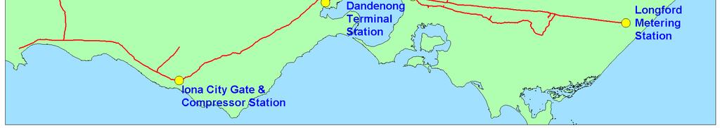
5 Victorian Natural Gas System APA Group Presentation 5
6 Safety Standards AS/NZS AS Functional safety of electrical/electronic/programmable electronic safety-related systems General requirements AS Functional safety of electrical/electronic/programmable electronic safety-related systems Requirements for electrical/electronic/programmable electronic safety-related systems AS Functional safety of electrical/electronic/programmable electronic safety-related systems Software requirements AS Functional safety of electrical/electronic/programmable electronic safety-related systems Definition and abbreviations AS Functional safety of electrical/electronic/programmable electronic safety-related systems Examples of methods for the determination of safety integrity levels AS Functional safety of electrical/electronic/programmable electronic safety-related systems Guidelines on the application of AS and AS AS Functional safety of electrical/electronic/programmable electronic safety-related systems Overview of techniques and measures APA Group Presentation 6
7 Safety Standards - AS/NZS 61511, AS 3814 AS IEC Functional safety - Safety instrumented systems for the process industry sector - Framework, definitions, systems, hardware and software requirements AS IEC Functional safety - Safety instrumented systems for the process industry sector - Guidelines for the application of AS IEC AS IEC Functional safety - Safety instrumented systems for the process industry sector - Guidance for the determination of the required safety integrity levels AS Appliances Industrial and Commercial Gas Fired APA Group Presentation 7
8 Safety Instrumented Systems Safety systems have been used for many years in process industries to perform safety instrumented functions. If instrumentation is to be effectively used for safety, it is essential that this instrumentation achieve certain minimum standards and performance levels. AS NZS addresses Safety Instrumented Systems for all types of industrial applications. A Safety Instrumented System includes all components and subsystems necessary to carry out the safety instrumented function from sensor(s) to final element(s). IEC61511 addresses Safety Instrumented Systems applicable the Process Industries only. AS NZS applies to Safety Instrumented Systems for the Process Industry that is based on electrical / electronic / programmable electronic technology. Where other technologies are used for logic solvers, the basic principles of this standard should be applied. This standard also addresses the Safety Instrumented System s sensors and final elements regardless of the applied technology. IEC61508 and IEC61511 were recognized by the Australian Standards in the year 2000 APA Group Presentation 8
9 AS/NZS AS NZS 2885 does NOT currently call up AS NZS nor AS NZS However, specific levels of control for pressure reduction stations are mandated in AS/NZS clauses and Safety systems are now commonly used in the gas industry for safety functions in compressor stations, LNG facilities and processing plant, as well as certain Type B appliances: AS/NZS 3814 requires compliance to AS/NZS and for Type B fuel-fired appliances controlled by programmable electronic systems. This applies to the following appliances Gas turbine engines (eg Solar Saturns, Centaurs, Taurus, Mars) Standby generators Waterbath heaters For gas pipeline operators, assessment of compliance to engineering principles in AS/NZS 3814, as with other aspects of design for the gas pipeline control, is managed under the Pipeline Safety Case APA Group Presentation 9
10 Large multi-run pressure reduction stations Overpressure protection of pipelines at pressure reduction stations using pressure relief valves may not be acceptable due to offsite hazards. Functional requirements for large multi-run pressure reduction stations in Victoria are becoming more demanding due to 4-hourly gas market demands, including frequent remote pressure setpoint control, stop/start operation and interaction with gas compressors Increased pipeline operating pressure, leading to higher pressure drops and potential low temperatures due to Joule-Thompson cooling APA Group Presentation 10
11 Multi-run stations Major Victorian multi-run stations (planned capacity) Dandenong City Gate (7 runs) Wollert City Gate (4 runs) Brooklyn Corio Pipeline (BCP) City Gate (5 runs) Brooklyn Lara Pipeline (BLP) City Gate (5 runs) Lara SWP City Gate (5 runs) Wollert and Brooklyn projects are currently under construction Design is complete for Dandenong and Lara projects APA Group Presentation 11
12 APA Group Presentation 12
13 APA Group Presentation 13

14 APA Group Presentation 14

15 APA Group Presentation 15

16 APA Group Presentation 16
 Brooklyn Corio Pipeline (BCP CG) (previously BCG) APA Group")
17 Future Brooklyn Ballan Pipeline (BBP CG) (currently Brooklyn PL) Brooklyn Lara Pipeline (BLP CG) Brooklyn Corio Pipeline (BCP CG) (previously BCG) APA Group Presentation 17

18 APA Group Presentation 18
19 Dandenong City Gate Commissioned in 1969 Initially 2 regulator runs, each with active and monitor regulators and station PSVs Growth led to current 7 regulator runs RTU to monitor and control pressure PSVs replaced with electrical relay over-pressure trip of run inlet valves circa 1979 (ie PSHH trips the station) PSVs removed due to proximity of flare Slamshut controller replaced with separate RTU circa 1985 Approximately 65% of Melbourne s daily gas flows through the station (about 80% annually). The station operates continuously. APA Group Presentation 19
20 Design Issues Regulators fail-open design Inlet valves fail-last design Common mode failure concern Undetected regulator failure Operator should not have to open/close runs to avoid overpressure Additional heater differential pressure losses affect capacity Control algorithms different at other sites AS requires max MAOP tolerance 1% Flow imbalance between runs may lead to noise, erosion and filter failure APA Group Presentation 20
21 Design Concept Maintain multi-run station concept (ie retain headers) Single active regulator, fail-closed Upstream slamshut valve (SSV), fail-closed Standardised control algorithm Standardised test program (routine run safety verification tests) Remote outlet pressure setpoint control Provide improved operator interface (HMI) for maintenance APA Group Presentation 21
22 Project Objectives Meet safety objectives per AS61511 Minimise capital expense Pressure control per AS2885.1:2007 High station availability 99.99% Retain contract station differential pressure and peak flowrate design basis Maintainability using common sub-components APA Group Presentation 22
23 AS2885.1:2007 Clause Pipeline Pressure Control The following requirements shall be implemented in design and operation of the pipeline pressure control. MAOP under steady state conditions For pipelines intended to be operated at a set point equal to MAOP, the control system shall control the maximum pressure within a tolerance of 1%. Pressure control and a second pressure limiting system are mandatory. The second (pressure limiting) system may be a second pressure control or an overpressure shut-off system or pressure relief. Pressure control system performance Pressure control and overpressure protection systems and their components shall have performance characteristics and properties necessary for their reliable and adequate operation during the design life of the pipeline. APA Group Presentation 23
24 AS2885.1:2007 Clause Pipeline Facility Control Most facilities are remote from their point of operation and generally designed for unattended operation. Each facility shall be designed with a local control system to manage the safe operation of the facility. The local control system shall. (a) Continue to operate in the event of a communications failure; (b) If electric powered, be provided with an uninterruptible power supply with sufficient capacity to ensure continuous operation through a reasonable power outage; (c) Use reliable technology; (d) Be designed to fail in a safe manner; and (e) Be designed with appropriate security. Each facility may also be configured to enable remote monitoring or control of the facility. APA Group Presentation 24
25 SIL Assignment and Verification Analyse SIF overpressure downstream pipeline Determine SIL achieved using current design with the existing RTUs and regulators Determine SIL achievable using proposed design with single FC regulator, SSV and TMR PLC Identify required maintenance regime Select current BLP project as test case Use standard GasNet panels Use BLP regulator PID design APA Group Presentation 25

26 Control Schematic for Regulator APA Group Presentation 26
27 PID for Regulator Run APA Group Presentation 27
28 Active Regulator APA Group Presentation 28
29 Regulator characteristics Fail closed valve Electronic and pneumatic positioner (fails to pneumatic on loss of PES) Common station backup pneumatic controller (balances load across runs) Diagnostic inputs include closed limit switch and position feedback Level 1 fault - valve detected faulty (eg sticky) with persistent control position discrepancy. Run inlet valve closes. Level 2 fault high outlet pressure and control valve not fully closed. Run inlet valve closes. Level 3 fault high outlet pressure. Close all run inlet valves. Level 4 fault high high outlet pressure. Inlet valve closes under pneumatic control. APA Group Presentation 29
30 Fault Tree Models Pressure Control Electronic Pressure Control SIF-10 Fisher DVC6000 (4-20mA) Positioner Bristol Control Wave (Defined by AS61508) FPCY E-4 RTU 4.257E GATE-6-12 GATE-6-13 GATE-6-14 GATE-6-15 Impulse Line - Clean Service Generic Pressure Transmitter Impulse Line - Clean Service Generic Pressure Transmitter Impulse Line - Clean Service Generic Pressure Transmitter 1.095E E E E E E-3 IMPULSE-LINE-(CLEAN)-PTA PT-62755A IMPULSE-LINE-(CLEAN)-PTB PT-62755B IMPULSE-LINE-(CLEAN)-PTC PT-62755C SIF-10 - Electronic Pressure Control APA 2007/02/21 Group Presentation Page 6 30
31 Fault Tree Model TMR Based Control Site Wide Pressure Control (Tricon) RF-24A Triconex Tricon TRICON 3.520E GATE-32-0 GATE-27-1 GATE-27-2 GATE-27-3 Impulse Line - Clean Service Generic Pressure Transmitter Impulse Line - Clean Service Generic Pressure Transmitter Impulse Line - Clean Service Generic Pressure Transmitter 2.500E E E E E E-7 IMPULSE-LINE-(R)-PTA PT-62755A(R) IMPULSE-LINE-(R)-PTB PT-62755B(R) IMPULSE-LINE-(R)-PTC PT-62755C(R) RF-24A - Site Wide Pressure Control (Tricon) APA 2007/02/20 Group Presentation Page 33 31
32 Slamshut valve APA Group Presentation 32
33 Slamshut valve characteristics Fail closed valve Independent pneumatic high high and low low pressure trip will close the valve Electronic open (option) and close control: Open is conditional on outlet pressure Close on PSHH or manual command from DCS or HMI Auto/Manual control on slamshut panel. Alarm active while in manual. APA Group Presentation 33
34 Standard Panel for Slamshut APA Group Presentation 34
35 Fault Tree Slamshut system Slam Shut RF-28 Fisher 4660 Pressure Switch Pneumatic (OREDA 84) (Pilot Booster) Generic 2/3 Way (Valve Actuator) Generic 2/3 Way 5.700E E E-6 PSH PYH-62151A PYH-62151B GATE-37-0 Trunnion Ball UV E-7 Bettis CB Series Valve Actuator (Exida) UZ E-6 RF-28 - Slam Shut APA 2007/02/21 Group Presentation Page 37 35
36 Pneumatic (OREDA 84) PSH E-6 PYH-62151A 2.095E-6 GATE PYH-62151B 2.095E-6 UV E-7 GATE GATE-31-0 GATE-31-5 (Exida) UZ E-6 FPCY-62154(R) Pressure Reducing FPCV-62154A(R) 9.150E E-5 GATE GATE Site Wide Pressure Control 32 RF E-7 IMPULSE-LINE-(CLEAN)-PCA GATE (Foxboro Data) PC E-7 GATE GATE Pneumatic (OREDA 84) PSH E-6 Burkert 6014 / exida) 2.390E-7 UY (FAIL-ON) PYH-62251A 2.095E-6 Pneumatic Relay (US DOE) 2.000E-5 UY-62154A-(FAIL-ON) GATE PYH-62251B 2.095E-6 UV E-7 GATE GATE-31-1 GATE-31-6 (Exida) UZ E-7 IMPULSE-LINE-(CLEAN)-PCB 1.630E-6 (Foxboro Data) PC Pressure Reducing FPCV-62254A(R) 5.620E E-5 GATE GATE GATE Burkert 6014 / exida) GATE E-7 UY (FAIL-ON) FPCY-62254(R) 9.150E-7 GATE Pneumatic Relay (US DOE) 2.000E-5 UY-62254A-(FAIL-ON) Pneumatic (OREDA 84) PSH E-6 Site Wide Pressure Control 32 RF-24 PYH-62351A 2.095E-6 GATE PYH-62351B 2.095E-6 UV E-7 GATE Valve) Tot al Failures RF-26 GATE-31-2 GATE-31-7 (Exida) UZ E-7 IMPULSE-LINE-(CLEAN)-PCC 1.630E-6 (Foxboro Data) PC Pressure Reducing FPCV-62354A(R) 5.620E E-5 GATE GATE GATE Burkert 6014 / exida) GATE E-7 UY (FAIL-ON) FPCY-62354(R) 9.150E-7 GATE Pneumatic Relay (US DOE) 2.000E-5 UY-62354A-(FAIL-ON) Pneumatic (OREDA 84) PSH E-6 Site Wide Pressure Control 32 RF-24 PYH-62451A 2.095E-6 GATE PYH-62451B 2.095E-6 UV E-7 GATE GATE-31-3 GATE-31-8 (Exida) UZ E-7 IMPULSE-LINE-(CLEAN)-PCD 1.630E-6 (Foxboro Data) PC Pressure Reducing FPCV-62454A(R) 5.620E E-5 GATE GATE GATE Burkert 6014 / exida) GATE E-7 UY (FAIL-ON) FPCY-62454(R) 9.150E-7 GATE Pneumatic Relay (US DOE) 2.000E-5 UY-62454A-(FAIL-ON) Pneumatic (OREDA 84) PSH E-6 Site Wide Pressure Control 32 RF-24 PYH-62551A 2.095E-6 GATE PYH-62551B 2.095E-6 UV E-7 GATE GATE-31-4 GATE-31-9 (Exida) UZ E-7 IMPULSE-LINE-(CLEAN)-PCE 1.630E-6 (Foxboro Data) PC Pressure Reducing FPCV-62554A(R) 5.620E E-5 GATE GATE GATE Burkert 6014 / exida) GATE E-7 UY (FAIL-ON) FPCY-62554(R) 9.150E-7 GATE Pneumatic Relay (US DOE) 2.000E-5 UY-62554A-(FAIL-ON) Site Wide Pressure Control 32 RF-24 Fault Tree Model RTU Whole System Site Wide Train Controls (Single Fisher 4660 Pressure Switch (Pilot Booster) Generic 2/3 Way (Valve Actuator) Generic 2/3 Way Valve (Oreda 2002 pp 757) Fisher 4660 Pressure Switch (Pilot Booster) Generic 2/3 Way (Valve Actuator) Generic 2/3 Way Valve (Oreda 2002 pp 757) Fisher 4660 Pressure Switch (Pilot Booster) Generic 2/3 Way (Valve Actuator) Generic 2/3 Way Valve (Oreda 2002 pp 757) Fisher 4660 Pressure Switch (Pilot Booster) Generic 2/3 Way (Valve Actuator) Generic 2/3 Way Valve (Oreda 2002 pp 757) Fisher 4660 Pressure Switch (Pilot Booster) Generic 2/3 Way (Valve Actuator) Generic 2/3 Way Valve (Oreda 2002 pp 757) Trunnion Ball Bettis CB Series Valve Actuator Trunnion Ball Bettis CB Series Valve Actuator Trunnion Ball Bettis CB Series Valve Act uat or Trunnion Ball Bettis CB Series Valve Act uat or Trunnion Ball Bettis CB Series Valve Act uat or Fisher DVC6000 (4-20mA) Positioner Fisher DVC6000 (4-20mA) Positioner Fisher DVC6000 (4-20mA) Positioner Fisher DVC6000 (4-20mA) Positioner Fisher DVC6000 (4-20mA) Positioner Impulse Line - Clean Service Foxboro 43APG Pneumatic Controller Solenoid (Failed Energised) (Burkert Impulse Line - Clean Service Foxboro 43APG Pneumatic Controller Solenoid (Failed Energised) (Burkert Impulse Line - Clean Service Foxboro 43APG Pneumatic Controller Solenoid (Failed Energised) (Burkert Impulse Line - Clean Service Foxboro 43APG Pneumatic Controller Solenoid (Failed Energised) (Burkert Impulse Line - Clean Service Foxboro 43APG Pneumatic Controller Solenoid (Failed Energised) (Burkert RF-26 - Site Wide Train Controls (Single Valve) Total Failures 2007/02/20 Page 31 APA Group Presentation 36
37 Pneumatic (OREDA 84) PSH E-6 PYH-62151A 2.095E-6 GATE PYH-62151B 2.095E-6 UV E-7 GATE GATE-31-0 GATE-31-5 (Exida) UZ E-6 FPCY-62154(R) Pressure Reducing FPCV-62154A(R) 9.150E E-5 GATE GATE Site Wide Pressure Control 32 RF E-7 IMPULSE-LINE-(CLEAN)-PCA GATE (Foxboro Data) PC E-7 GATE GATE Pneumatic (OREDA 84) PSH E-6 Burkert 6014 / exida) 2.390E-7 UY (FAIL-ON) PYH-62251A 2.095E-6 Pneumatic Relay (US DOE) 2.000E-5 UY-62154A-(FAIL-ON) GATE PYH-62251B 2.095E-6 UV E-7 GATE GATE-31-1 GATE-31-6 (Exida) UZ E-7 IMPULSE-LINE-(CLEAN)-PCB 1.630E-6 (Foxboro Data) PC Pressure Reducing FPCV-62254A(R) 5.620E E-5 GATE GATE GATE Burkert 6014 / exida) GATE E-7 UY (FAIL-ON) FPCY-62254(R) 9.150E-7 GATE Pneumatic Relay (US DOE) 2.000E-5 UY-62254A-(FAIL-ON) Pneumatic (OREDA 84) PSH E-6 Site Wide Pressure Control 32 RF-24 PYH-62351A 2.095E-6 GATE PYH-62351B 2.095E-6 UV E-7 GATE RF-26A GATE-31-2 GATE-31-7 (Exida) UZ E-7 IMPULSE-LINE-(CLEAN)-PCC 1.630E-6 (Foxboro Data) PC Pressure Reducing FPCV-62354A(R) 5.620E E-5 GATE GATE GATE Burkert 6014 / exida) GATE E-7 UY (FAIL-ON) FPCY-62354(R) 9.150E-7 GATE Pneumatic Relay (US DOE) 2.000E-5 UY-62354A-(FAIL-ON) Pneumatic (OREDA 84) PSH E-6 Site Wide Pressure Control 32 RF-24 PYH-62451A 2.095E-6 GATE PYH-62451B 2.095E-6 UV E-7 GATE GATE-31-3 GATE-31-8 (Exida) UZ E-7 IMPULSE-LINE-(CLEAN)-PCD 1.630E-6 (Foxboro Data) PC Pressure Reducing FPCV-62454A(R) 5.620E E-5 GATE GATE GATE Burkert 6014 / exida) GATE E-7 UY (FAIL-ON) FPCY-62454(R) 9.150E-7 GATE Pneumatic Relay (US DOE) 2.000E-5 UY-62454A-(FAIL-ON) Pneumatic (OREDA 84) PSH E-6 Site Wide Pressure Control 32 RF-24 PYH-62551A 2.095E-6 GATE PYH-62551B 2.095E-6 UV E-7 GATE GATE-31-4 GATE-31-9 (Exida) UZ E-7 IMPULSE-LINE-(CLEAN)-PCE 1.630E-6 (Foxboro Data) PC Pressure Reducing FPCV-62554A(R) 5.620E E-5 GATE GATE GATE Burkert 6014 / exida) GATE E-7 UY (FAIL-ON) FPCY-62554(R) 9.150E-7 GATE Pneumatic Relay (US DOE) 2.000E-5 UY-62554A-(FAIL-ON) Site Wide Pressure Control 32 RF-24 Fault Tree Model TMR Whole System Site Wide Train Controls (Single Valve) Total Failures (Tricon) Fisher 4660 Pressure Switch (Pilot Booster) Generic 2/3 Way (Valve Actuator) Generic 2/3 Way Valve (Oreda 2002 pp 757) Fisher 4660 Pressure Switch (Pilot Booster) Generic 2/3 Way (Valve Actuator) Generic 2/3 Way Valve (Oreda 2002 pp 757) Fisher 4660 Pressure Switch (Pilot Booster) Generic 2/3 Way (Valve Actuator) Generic 2/3 Way Valve (Oreda 2002 pp 757) Fisher 4660 Pressure Switch (Pilot Booster) Generic 2/3 Way (Valve Actuator) Generic 2/3 Way Valve (Oreda 2002 pp 757) Fisher 4660 Pressure Switch (Pilot Booster) Generic 2/3 Way (Valve Actuator) Generic 2/3 Way Valve (Oreda 2002 pp 757) Trunnion Ball Bettis CB Series Valve Actuator Trunnion Ball Bettis CB Series Valve Actuator Trunnion Ball Bettis CB Series Valve Act uat or Trunnion Ball Bettis CB Series Valve Act uat or Trunnion Ball Bettis CB Series Valve Act uat or Fisher DVC6000 (4-20mA) Positioner Fisher DVC6000 (4-20mA) Positioner Fisher DVC6000 (4-20mA) Positioner Fisher DVC6000 (4-20mA) Positioner Fisher DVC6000 (4-20mA) Positioner Impulse Line - Clean Service Foxboro 43APG Pneumatic Controller Solenoid (Failed Energised) (Burkert Impulse Line - Clean Service Foxboro 43APG Pneumatic Controller Solenoid (Failed Energised) (Burkert Impulse Line - Clean Service Foxboro 43APG Pneumatic Controller Solenoid (Failed Energised) (Burkert Impulse Line - Clean Service Foxboro 43APG Pneumatic Controller Solenoid (Failed Energised) (Burkert Impulse Line - Clean Service Foxboro 43APG Pneumatic Controller Solenoid (Failed Energised) (Burkert RF-26A - Site Wide Train Controls (Single Valve) Total Failures (Tricon) 2007/02/20 Page 34 APA Group Presentation 37
38 Layers Of Protection Analysis Project: Gasnet Brooklyn Control System Rebuild SIF Identifier: SIF-001 SIF Gas High Pressure Description Area P& ID Safety Econ. Impact Event Initiating Initiating Category Envir. Category Description Cause Likelihood and Target Category and and Target Target Risk Risk Risk 7a 7b 7c 7d 7e Layers of Protection SIF Integrity Level Compliance Inter Additional IPL additional General Basic Process Alarms mediate SIL Mitigated EIL Actual PFD of Conclusion Economical Safety Event Envir onm e ntal the SIF mitigation, mitigation, event Process Control & Operator restricted dikes, pressure Likelihood Design System Response Likelihood access relief /Year A$ Occupancy Ignition Fatality Factor Factor 1 1 Regulation Train Over Pressure Supply Regulator Valve Mechanical Failure Fatalities Minor 10,000,000 Not Designed to No Protection Contain Possible from Pressure Off Redundant Site (GPU Pneumatic Gasnet) Controls Alarms Downstream Slam Shut Pressure Relief Capacity Inadequate Occupancy assumed to be less than 876 man hours per year. Ignition data from Oreda Fire and Gas Study Target Target Target E E E E E E E E E E E E-01 SIL 0 EIL 0 AIL 0 8.3E E-09 2 Regulation Train Over Pressure Supply Regulator Electronic Control System Failure Fatalities Minor 10,000,000 Not Designed to Protection Contain Possible from Pressure Off Redundant Site (GPU Pneumatic Gasnet) Controls Alarms Downstream Slam Shut Pressure Relief Capacity Inadequate Occupancy assumed to be less than 876 man hours per year. Ignition data from Oreda Fire and Gas Study Target Target Target E E E E E E E E E E E E+00 SIL 0 EIL 0 AIL 0 8.3E E-10 3 Regulation Train Over Pressure Process Back Pressure Fatalities Minor 10,000,000 Not Designed to Contain Pressure Off Site (GPU Gasnet) Yes Alarms Downstream Slam Shut Pressure Relief Capacity Inadequate Occupancy assumed to be less than 876 man hours per year. Ignition data from Oreda Fire and Gas Study Target Target Target E E E E E E E E E E E E+00 SIL 0 EIL 0 AIL 0 8.3E E-09 Prepared by: Reviewed Summary SIL EIL AIL by: 1.53E+00 Title Name Signature Date Title Name Signature Date 4.6E E-01 SIF-001 FS Engineer Allan Gibson 16-Mar-07 Process Alan Burt SIL 0 EIL 0 AIL 0 Manager Title Name Signature Date Process David Little Engineer Total Mitigated Safety Event Likelihood 5.383E-09 Less than target Yes APA Group Presentation 38
39 Safety The safety system for these valves is primarily pneumatic, with the ability to be remotely operated from the network control room and as such is subject to the failure rates of these components and the low accuracy of switching compared to the electronic equivalents. Adding the electronic diagnostics reduces the failure rate for the pneumatic safety system from 3.6E-2 to 1.05E-2 for the RTU based solution improving slightly to 9.3E- 003 for a TMR based solution by bypassing some of the pneumatic logic and providing a parallel trip path. These are however again limited by the reliability of the safety system valves which places a floor under the possible shutdown system performance. The actual experienced failure rate for the slam shut system has been in excess of 8.26E-3 based on proven in use data received from GasNet and this has been used in the above event trees. APA Group Presentation 39
40 Control system implementation Assuming the reliability of the Bristol RTU is inline with industrial standards a spurious trip can be expected due to a control system failure at approximately 11.5 year intervals. This means that a failure will probably occur during the life of the plant due to this cause. Replacing the Bristol RTU with a typical TMR based system will raise this to the 300 to 3000 year range. The probability of a failure of a 2oo3 voting system for the pressure transmitters used in control of either system is so low as to be irrelevant, at per year unless a common cause is considered such as a lighting strike or miss-calibration. These causes are still far less likely than an RTU failure which dominates the probability of failure. APA Group Presentation 40
41 Control and Slamshut Valve Reliability Single Control Valve: The Single Control Valve control implementation will result in a failure requiring unscheduled maintenance about every 0.7 years for a station with 5 trains, primarily driven by control valve failures. Installing a TMR based control system will raise this to 0.8 years. Dual Control Valve The Dual Control Valve control implementation will result in a failure requiring unscheduled maintenance about every 0.41 years for a station with 5 trains, again primary driven by control valve failures (ie about double the rate for single control valve installation). Installing a TMR based control system will raise this to 0.42 years, a barely noticeable change. Slam Shut Valve It is estimated that an individual slam shut valve will close spuriously about every 10 years APA Group Presentation 41
42 Conclusions Safety target is met with one regulator per run provided a TMR PLC is used TMR + Reg + SSV = 2*RTU + 2*Reg + SSV For multi-run stations, use of the TMR is more economic because of the cost savings of the regulators. For the same station capacity: Dandenong single regulator solution requires 7 regulators and 7 SSVs Dandenong dual regulator solution requires 20 regulators and 10 SSVs For dual run (primary and standby runs) a simpler instrumented design is likely to be more economic. Diagnostic systems are required to detect failed/faulty regulator Records of failure data or SIL rating are required for all components in the safety system APA Group Presentation 42
43 Program Rollout Tricon selected for initial city gate sites at Brooklyn and Wollert 2*Trident selected for 4 ea Brooklyn heater BMS Interface via TUV serial link to Compressor Station Tricons at Brooklyn and Wollert Standard function blocks Standard field devices APA Group Presentation 43
44 We Deliver Energy APA Group Presentation 44
High Integrity Pressure Protection Systems HIPPS
 High Integrity Pressure Protection Systems HIPPS HIPPS > High Integrity Pressure Protection Systems WHAT IS A HIPPS The High Integrity Pressure Protection Systems (HIPPS) is a mechanical and electrical
Implementing IEC Standards for Safety Instrumented Systems
 Implementing IEC Standards for Safety Instrumented Systems ABHAY THODGE TUV Certificate: PFSE-06-607 INVENSYS OPERATIONS MANAGEMENT What is a Safety Instrumented System (SIS)? An SIS is designed to: respond
SIL explained. Understanding the use of valve actuators in SIL rated safety instrumented systems ACTUATION
 SIL explained Understanding the use of valve actuators in SIL rated safety instrumented systems The requirement for Safety Integrity Level (SIL) equipment can be complicated and confusing. In this document,
L&T Valves Limited SAFETY INTEGRITY LEVEL (SIL) VERIFICATION FOR HIGH INTEGRITY PRESSURE PROTECTION SYSTEM (HIPPS) Report No.
 VERIFICATION FOR HIGH INTEGRITY PRESSURE PROTECTION SYSTEM (HIPPS) Report No.") L&T Valves Limited TAMIL NADU SAFETY INTEGRITY LEVEL (SIL) VERIFICATION FOR HIGH INTEGRITY PRESSURE PROTECTION SYSTEM (HIPPS) MAY 2016 Report No. 8113245702-100-01 Submitted to L&T Valves Ltd. Report by
L&T Valves Limited TAMIL NADU SAFETY INTEGRITY LEVEL (SIL) VERIFICATION FOR HIGH INTEGRITY PRESSURE PROTECTION SYSTEM (HIPPS) MAY 2016 Report No. 8113245702-100-01 Submitted to L&T Valves Ltd. Report by
Every things under control High-Integrity Pressure Protection System (HIPPS)
") Every things under control www.adico.co info@adico.co Table Of Contents 1. Introduction... 2 2. Standards... 3 3. HIPPS vs Emergency Shut Down... 4 4. Safety Requirement Specification... 4 5. Device Integrity
Every things under control www.adico.co info@adico.co Table Of Contents 1. Introduction... 2 2. Standards... 3 3. HIPPS vs Emergency Shut Down... 4 4. Safety Requirement Specification... 4 5. Device Integrity
innova-ve entrepreneurial global 1
 www.utm.my innova-ve entrepreneurial global Safety Integrity Level (SIL) is defined as: Relative level of risk-reduction provided by a safety function to specify a target level of risk reduction. SIL is
EMERGENCY SHUT-DOWN RELIABILITY ADVANTAGE
 Your partner in Fluid Control Solutions EMERGENCY SHUT-DOWN RELIABILITY ADVANTAGE George Cao 06 May, 2011 1. ESD Overview Why Do You Need ESD Solution? Safety! Safety!! Safety!!! Safety Is a Must! The
This manual provides necessary requirements for meeting the IEC or IEC functional safety standards.
 Instruction Manual Supplement Safety manual for Fisher Vee-Ball Series Purpose This safety manual provides information necessary to design, install, verify and maintain a Safety Instrumented Function (SIF)
Solenoid Valves used in Safety Instrumented Systems
 I&M V9629R1 Solenoid Valves used in Safety Instrumented Systems Operating Manual in accordance with IEC 61508 ASCO Valves Page 1 of 7 Table of Contents 1 Introduction...3 1.1 Terms and Abbreviations...3
SIL Safety Manual. ULTRAMAT 6 Gas Analyzer for the Determination of IR-Absorbing Gases. Supplement to instruction manual ULTRAMAT 6 and OXYMAT 6
 ULTRAMAT 6 Gas Analyzer for the Determination of IR-Absorbing Gases SIL Safety Manual Supplement to instruction manual ULTRAMAT 6 and OXYMAT 6 ULTRAMAT 6F 7MB2111, 7MB2117, 7MB2112, 7MB2118 ULTRAMAT 6E
Valve Communication Solutions. Safety instrumented systems
 Safety instrumented systems Safety Instrumented System (SIS) is implemented as part of a risk reduction strategy. The primary focus is to prevent catastrophic accidents resulting from abnormal operation.
Safety manual for Fisher GX Control Valve and Actuator
 Instruction Manual Supplement GX Valve and Actuator Safety manual for Fisher GX Control Valve and Actuator Purpose This safety manual provides information necessary to design, install, verify and maintain
FP15 Interface Valve. SIL Safety Manual. SIL SM.018 Rev 1. Compiled By : G. Elliott, Date: 30/10/2017. Innovative and Reliable Valve & Pump Solutions
 SIL SM.018 Rev 1 FP15 Interface Valve Compiled By : G. Elliott, Date: 30/10/2017 FP15/L1 FP15/H1 Contents Terminology Definitions......3 Acronyms & Abbreviations...4 1. Introduction...5 1.1 Scope.. 5 1.2
DeZURIK. KSV Knife Gate Valve. Safety Manual
 KSV Knife Gate Valve Safety Manual Manual D11035 August 29, 2014 Table of Contents 1 Introduction... 3 1.1 Terms... 3 1.2 Abbreviations... 4 1.3 Product Support... 4 1.4 Related Literature... 4 1.5 Reference
Achieving Compliance in Hardware Fault Tolerance
 Mirek Generowicz FS Senior Expert (TÜV Rheinland #183/12) Engineering Manager, I&E Systems Pty Ltd Abstract The functional safety standards ISA S84/IEC 61511 (1 st Edition, 2003) and IEC 61508 both set
Instrumented Safety Systems
 Instrumented Safety Systems Engineered Valve Systems for Control and Safety Applications HIPPS Final Elements DINO OLIVIERI Mokveld Agent AIS ISA Giornata di studio HIPPS Agenda The loop Final Elements
RESILIENT SEATED BUTTERFLY VALVES FUNCTIONAL SAFETY MANUAL
 Per IEC 61508 and IEC 61511 Standards BRAY.COM Table of Contents 1.0 Introduction.................................................... 1 1.1 Terms and Abbreviations...........................................
Pneumatic QEV. SIL Safety Manual SIL SM Compiled By : G. Elliott, Date: 8/19/2015. Innovative and Reliable Valve & Pump Solutions
 SIL SM.0010 1 Pneumatic QEV Compiled By : G. Elliott, Date: 8/19/2015 Contents Terminology Definitions......3 Acronyms & Abbreviations..4 1. Introduction 5 1.1 Scope 5 1.2 Relevant Standards 5 1.3 Other
Ultima. X Series Gas Monitor
 Ultima X Series Gas Monitor Safety Manual SIL 2 Certified " The Ultima X Series Gas Monitor is qualified as an SIL 2 device under IEC 61508 and must be installed, used, and maintained in accordance with
Section 1: Multiple Choice
 CFSP Process Applications Section 1: Multiple Choice EXAMPLE Candidate Exam Number (No Name): Please write down your name in the above provided space. Only one answer is correct. Please circle only the
DeZURIK Double Block & Bleed (DBB) Knife Gate Valve Safety Manual
 Knife Gate Valve Safety Manual") Double Block & Bleed (DBB) Knife Gate Valve Safety Manual Manual D11044 September, 2015 Table of Contents 1 Introduction... 3 1.1 Terms... 3 1.2 Abbreviations... 4 1.3 Product Support... 4 1.4 Related
Double Block & Bleed (DBB) Knife Gate Valve Safety Manual Manual D11044 September, 2015 Table of Contents 1 Introduction... 3 1.1 Terms... 3 1.2 Abbreviations... 4 1.3 Product Support... 4 1.4 Related
Safety Integrity Verification and Validation of a High Integrity Pressure Protection System (HIPPS) to IEC 61511
 to IEC 61511") Safety Integrity Verification and Validation of a High Integrity Pressure Protection System (HIPPS) to IEC 61511 Abstract Author: Colin Easton ProSalus Limited ~ Independent Safety Consultants A key requirement
Safety Integrity Verification and Validation of a High Integrity Pressure Protection System (HIPPS) to IEC 61511 Abstract Author: Colin Easton ProSalus Limited ~ Independent Safety Consultants A key requirement
DeZURIK. KGC Cast Knife Gate Valve. Safety Manual
 KGC Cast Knife Gate Valve Safety Manual Manual D11036 August 29, 2014 Table of Contents 1 Introduction... 3 1.1 Terms... 3 1.2 Abbreviations... 4 1.3 Product Support... 4 1.4 Related Literature... 4 1.5
Partial Stroke Testing for SRD991 and SRD960
 Technical Information 09.11 TI EVE0105 PST-(en) Partial Stroke Testing for SRD991 and SRD960 Final control elements in Emergency Shutdown (ESD) applications such as ON-OFF-, Blow Down and Venting-Valves
SPR - Pneumatic Spool Valve
 SIL SM.008 Rev 7 SPR - Pneumatic Spool Valve Compiled By : G. Elliott, Date: 31/08/17 Contents Terminology Definitions:... 3 Acronyms & Abbreviations:... 4 1.0 Introduction... 5 1.1 Purpose & Scope...
TRI LOK SAFETY MANUAL TRI LOK TRIPLE OFFSET BUTTERFLY VALVE. The High Performance Company
 TRI LOK TRI LOK TRIPLE OFFSET BUTTERFLY VALVE SAFETY MANUAL The High Performance Company Table of Contents 1.0 Introduction...1 1.1 Terms and Abbreviations... 1 1.2 Acronyms... 1 1.3 Product Support...
Eutectic Plug Valve. SIL Safety Manual. SIL SM.015 Rev 0. Compiled By : G. Elliott, Date: 19/10/2016. Innovative and Reliable Valve & Pump Solutions
 SIL SM.015 Rev 0 Eutectic Plug Valve Compiled By : G. Elliott, Date: 19/10/2016 Contents Terminology Definitions......3 Acronyms & Abbreviations...4 1. Introduction..5 1.1 Scope 5 1.2 Relevant Standards
Solenoid Valves For Gas Service FP02G & FP05G
 SIL Safety Manual SM.0002 Rev 02 Solenoid Valves For Gas Service FP02G & FP05G Compiled By : G. Elliott, Date: 31/10/2017 Reviewed By : Peter Kyrycz Date: 31/10/2017 Contents Terminology Definitions......3
Reliability of Safety-Critical Systems Chapter 3. Failures and Failure Analysis
 Reliability of Safety-Critical Systems Chapter 3. Failures and Failure Analysis Mary Ann Lundteigen and Marvin Rausand mary.a.lundteigen@ntnu.no RAMS Group Department of Production and Quality Engineering
YT-3300 / 3301 / 3302 / 3303 / 3350 / 3400 /
 Smart positioner YT-3300 / 3301 / 3302 / 3303 / 3350 / 3400 / 3410 / 3450 Series SIL Safety Instruction. Supplement to product manual July. 2015 YTC Ver 1.06 1 Table of contents 1 Introduction... 3 1.1
Neles ValvGuard VG9000H Rev 2.0. Safety Manual
 Neles ValvGuard VG9000H Rev 2.0 Safety Manual 10SM VG9000H en 11/2016 2 Neles ValvGuard VG9000H Rev 2.0 Safety Manual Table of Contents 1 General information...3 1.1 Purpose of the document... 3 1.2 Description
Hydraulic (Subsea) Shuttle Valves
 Shuttle Valves") SIL SM.009 0 Hydraulic (Subsea) Shuttle Valves Compiled By : G. Elliott, Date: 11/3/2014 Contents Terminology Definitions......3 Acronyms & Abbreviations..4 1. Introduction 5 1.1 Scope 5 1.2 Relevant Standards
SIL SM.009 0 Hydraulic (Subsea) Shuttle Valves Compiled By : G. Elliott, Date: 11/3/2014 Contents Terminology Definitions......3 Acronyms & Abbreviations..4 1. Introduction 5 1.1 Scope 5 1.2 Relevant Standards
Failure Modes, Effects and Diagnostic Analysis. Rosemount Inc. Chanhassen, MN USA
 Failure Modes, Effects and Diagnostic Analysis Project: 3095MV Mass Flow Transmitter Customer: Rosemount Inc. Chanhassen, MN USA Contract No.: Q04/04-09 Report No.: Ros 04/04-09 R001 Version V1, Revision
Safety Manual. Process pressure transmitter IPT-1* 4 20 ma/hart. Process pressure transmitter IPT-1*
 Safety Manual Process pressure transmitter IPT-1* 4 20 ma/hart Process pressure transmitter IPT-1* Contents Contents 1 Functional safety 1.1 General information... 3 1.2 Planning... 4 1.3 Instrument parameter
Neles trunnion mounted ball valve Series D Rev. 2. Safety Manual
 Neles trunnion mounted ball valve Series D Rev. 2 Safety Manual 10SM D en 1/2017 2 Neles trunnion mounted ball valve, Series D Table of Contents 1 Introduction...3 2 Structure of the D series trunnion
A large Layer of Protection Analysis for a Gas terminal scenarios/ cause consequence pairs
 A large Layer of Protection Analysis for a Gas terminal 2000+ scenarios/ cause consequence pairs Richard Gowland European process Safety Centre The scope of the study was a large gas terminal handling
Partial Stroke Testing. A.F.M. Prins
 Partial Stroke Testing A.F.M. Prins Partial Stroke Testing PST in a safety related system. As a supplier we have a responsibility to our clients. What do they want, and what do they really need? I like
New Thinking in Control Reliability
 Doug Nix, A.Sc.T. Compliance InSight Consulting Inc. New Thinking in Control Reliability Or Your Next Big Headache www.machinerysafety101.com (519) 729-5704 Control Reliability Burning Questions from the
PREDICTING HEALTH OF FINAL CONTROL ELEMENT OF SAFETY INSTRUMENTED SYSTEM BY DIGITAL VALVE CONTROLLER
 PREDICTING HEALTH OF FINAL CONTROL ELEMENT OF SAFETY INSTRUMENTED SYSTEM BY DIGITAL VALVE CONTROLLER Riyaz Ali FIELDVUE Business Development Manager Fisher Controls Int'l., LLC. Marshalltown, IA 50158
Session One: A Practical Approach to Managing Safety Critical Equipment and Systems in Process Plants
 Session One: A Practical Approach to Managing Safety Critical Equipment and Systems in Process Plants Tahir Rafique Lead Electrical and Instruments Engineer: Qenos Botany Site Douglas Lloyd Senior Electrical
The Key Variables Needed for PFDavg Calculation
 Iwan van Beurden, CFSE Dr. William M. Goble, CFSE exida Sellersville, PA 18960, USA wgoble@exida.com July 2015 Update 1.2 September 2016 Abstract In performance based functional safety standards, safety
EXPERIMENT 1 AIR PRESSURE CONTROL SYSTEM
 EXPERIMENT 1 AIR PRESSURE CONTROL SYSTEM 1.0 OBJECTIVE To study the response of gas pressure control using PID controller. 2.0 INTRODUCTION TO THE APPARATUS a) The process plant consists of two air vessels
Failure Modes, Effects and Diagnostic Analysis
 Failure Modes, Effects and Diagnostic Analysis Project: 3051S SIS Pressure Transmitter, with Safety Feature Board, Software Revision 3.0 Customer: Rosemount Inc. Chanhassen, MN USA Contract No.: Ros 02/11-07
Industrial Compressor Controls Standard Custom
 Technical Seminars 2012 Industrial Compressor Controls Standard Custom CONTROLLING the power of ENERGY 1 TM 2 Woodward Compressor Controls Small Steam Turbine Driven Compressors (ITCC) 3 Simple Compressor
High performance disc valves Series Type BA, BK, BW, BM, BN, BO, BE, BH Rev Safety Manual
 High performance disc valves Series Type BA, BK, BW, BM, BN, BO, BE, BH Rev. 2.0 Safety Manual 10SM B Disc en 4/2018 2 High performance disc valves Series, Type BA, BK, BW, BM, BN, BO, BE, BH, Rev. 2.0
PROCESS AUTOMATION SIL. Manual Safety Integrity Level. Edition 2005 IEC 61508/61511
 PROCESS AUTOMATION Manual Safety Integrity Level SIL Edition 2005 IEC 61508/61511 With regard to the supply of products, the current issue of the following document is applicable: The General Terms of
The IEC61508 Operators' hymn sheet
 The IEC61508 Operators' hymn sheet A few key points for those Operators of plant or equipment that involve SIL rated safety functions*, trips or interlocks by The 61508 Association SAFETY INSTRUMENTED
Bespoke Hydraulic Manifold Assembly
 SIL SM.0003 1 Bespoke Hydraulic Manifold Assembly Compiled By : G. Elliott, Date: 12/17/2015 Contents Terminology Definitions......3 Acronyms & Abbreviations..4 1. Introduction 5 1.1 Scope 5 1.2 Relevant
Safety Manual VEGAVIB series 60
 Safety Manual VEGAVIB series 60 NAMUR Document ID: 32005 Contents Contents 1 Functional safety... 3 1.1 General information... 3 1.2 Planning... 4 1.3 Adjustment instructions... 6 1.4 Setup... 6 1.5 Reaction
VALIDATE LOPA ASSUMPTIONS WITH DATA FROM YOUR OWN PROCESS
 Honeywell Advanced Materials new Low-Global-Warming Refrigerant Plant in Geismar, LA Tony Downes Sept 2018 VALIDATE LOPA ASSUMPTIONS WITH DATA FROM YOUR OWN PROCESS A little about the presenter 1 Led over
Jamesbury Pneumatic Rack and Pinion Actuator
 Jamesbury Pneumatic Rack and Pinion Actuator Valv-Powr Series VPVL Rev. 3.0 Safety Manual 10SM VPVL en 5/2017 2 Jamesbury Pneumatic Rack and Pinion Actuator, Valv-Powr Series VPVL, Rev 3.0, Safety Manual
Section 1: Multiple Choice Explained EXAMPLE
 CFSP Process Applications Section 1: Multiple Choice Explained EXAMPLE Candidate Exam Number (No Name): Please write down your name in the above provided space. Only one answer is correct. Please circle
Safety Manual OPTISWITCH series relay (DPDT)
") Safety Manual OPTISWITCH series 5000 - relay (DPDT) 1 Content Content 1 Functional safety 1.1 In general................................ 3 1.2 Planning................................. 5 1.3 Adjustment
Safety Manual OPTISWITCH series 5000 - relay (DPDT) 1 Content Content 1 Functional safety 1.1 In general................................ 3 1.2 Planning................................. 5 1.3 Adjustment
SIL Safety Manual for Fisherr ED, ES, ET, EZ, HP, or HPA Valves with 657 / 667 Actuator
 SIL Safety Manual ED, ES, ET, EZ, HP, HPA Valves w/ 657/667 Actuator SIL Safety Manual for Fisherr ED, ES, ET, EZ, HP, or HPA Valves with 657 / 667 Actuator Purpose This safety manual provides information
A Complete Solution For HIPPS
 A Complete Solution For HIPPS Are You Also Facing These Challenges For Your HIPPS? PERFORMANCE Test and Working procedures / Safety Life Cycle ENVIRONMENT Fugitive Emissions / Reduce or Eliminate Flares
Fuel Gas Pressure Control Solutions for Fired Heaters and Boilers
 Fuel Gas Control Solutions for Fired Heaters and Boilers Solutions for safer and more reliable operation of fired heater fuel gas systems. Prevent process downtime by keeping your critical heaters online.
Safety Manual VEGAVIB series 60
 Safety Manual VEGAVIB series 60 Contactless electronic switch Document ID: 32002 Contents Contents 1 Functional safety... 3 1.1 General information... 3 1.2 Planning... 4 1.3 Adjustment instructions...
Understanding safety life cycles
 Understanding safety life cycles IEC/EN 61508 is the basis for the specification, design, and operation of safety instrumented systems (SIS) Fast Forward: IEC/EN 61508 standards need to be implemented
IE011: Process Control & Instrumentation Technology
 IE011: Process Control & Instrumentation Technology IE011 Rev.001 CMCT COURSE OUTLINE Page 1 of 8 Training Description: This intensive course covers fundamental and practical of instrumentation measurements
Failure Modes, Effects and Diagnostic Analysis
 Failure Modes, Effects and Diagnostic Analysis Project: Solenoid Drivers KFD2-SL2-(Ex)1.LK.vvcc KFD2-SL2-(Ex)*(.B).vvcc Customer: Pepperl+Fuchs GmbH Mannheim Germany Contract No.: P+F 06/09-23 Report No.:
Rosemount 2130 Level Switch
 Rosemount 2130 Level Switch Functional Safety Manual Manual Supplement Reference Manual Contents Contents 1Section 1: Introduction 1.1 Scope and purpose of the safety manual.............................................
SPECIAL PRINT. Innovative Control Technology. Safety in the Process Industry. SAMSON AG Manuel Hinkelmann Marcel Richter Monika Schneider
 Innovative Control Technology SPECIAL PRINT Safety in the Process Industry SAMSON AG Manuel Hinkelmann Marcel Richter Monika Schneider SAMSOMATIC Marc Belzer Translation of special print from: cav 6-2014,
Failure Modes, Effects and Diagnostic Analysis. Rosemount Inc. Chanhassen, Minnesota USA
 Failure Modes, Effects and Diagnostic Analysis Project: 3051C Pressure Transmitter Customer: Rosemount Inc. Chanhassen, Minnesota USA Contract No.: Ros 03/10-11 Report No.: Ros 03/10-11 R001 Version V1,
Knowledge, Certification, Networking
 www.iacpe.com Knowledge, Certification, Networking Page :1 of 71 Rev 01 Sept 2016 IACPE No 19, Jalan Bilal Mahmood 80100 Johor Bahru Malaysia The International of is providing the introduction to the Training
Proof Testing A key performance indicator for designers and end users of Safety Instrumented Systems
 Proof Testing A key performance indicator for designers and end users of Safety Instrumented Systems EUR ING David Green BEng(hons) CEng MIET MInstMC RFSE Ron Bell OBE BSc CEng FIET Engineering Safety
SIL Allocation. - Deterministic vs. risk-based approach - Layer Of Protection Analysis (LOPA) overview
 overview") SIL Allocation - Deterministic vs. risk-based approach - Layer Of Protection Analysis (LOPA) overview Origin and causes of accidents involving control system failure 44% Specification 20% Changes after
SIL Allocation - Deterministic vs. risk-based approach - Layer Of Protection Analysis (LOPA) overview Origin and causes of accidents involving control system failure 44% Specification 20% Changes after
FUEL GAS FIRING CONTROL RJ (Dick) Perry Safety Systems Consultant 6 June 2016
 Perry Safety Systems Consultant 6 June 2016") INTRODUCTION Fired equipment such as Heaters and Boilers, normally have to comply with either NFPA 85/86 or API 556 for North America and some other countries which apply such standards, or EN 746-2 for
INTRODUCTION Fired equipment such as Heaters and Boilers, normally have to comply with either NFPA 85/86 or API 556 for North America and some other countries which apply such standards, or EN 746-2 for
Commissioning and safety manual
 Commissioning and safety manual CNL35L DNL35L SIL2 LOREME 12, rue des Potiers d'etain Actipole BORNY - B.P. 35014-57071 METZ CEDEX 3 Phone 03.87.76.32.51 - Telefax 03.87.76.32.52 Contact: Commercial@Loreme.fr
4-sight Consulting. IEC case study.doc
 4-sight Consulting IEC 61511 / 61508 Case study 1 Contents 1 SUMMARY 4 2 INTRODUCTION 5 3 SCOPE OF THE STUDY 5 4 METHOD USED FOR THE STUDY 5 5 OPERATION OF THE TERMINAL 5 6 DESCRIPTION OF OVERFILL PREVENTION
Understanding the How, Why, and What of a Safety Integrity Level (SIL)
") Understanding the How, Why, and What of a Safety Integrity Level (SIL) Audio is provided via internet. Please enable your speaker (in all places) and mute your microphone. Understanding the How, Why, and
Understanding the How, Why, and What of a Safety Integrity Level (SIL) Audio is provided via internet. Please enable your speaker (in all places) and mute your microphone. Understanding the How, Why, and
Functional safety. Functional safety of Programmable systems, devices & components: Requirements from global & national standards
 Functional safety Functional safety of Programmable systems, devices & components: Requirements from global & national standards Matthias R. Heinze Vice President Engineering TUV Rheinland of N.A. Email
IE039: Practical Process Instrumentation & Automatic Control
 IE039: Practical Process Instrumentation & Automatic Control IE039 Rev.001 CMCT COURSE OUTLINE Page 1 of 8 Training Description: Process Control & Instrumentation is becoming an increasingly important
COMPARING PLUG & SEAT REGULATORS & CONTROL VALVES. Lamar Jones. Equipment Controls Company 4555 South Berkeley Lake Road Norcross, GA 30071
 COMPARING PLUG & SEAT REGULATORS & CONTROL VALVES Lamar Jones Equipment Controls Company 4555 South Berkeley Lake Road Norcross, GA 30071 INTRODUCTION The purpose of this paper will be to compare a plug
The Risk of LOPA and SIL Classification in the process industry
 The Risk of LOPA and SIL Classification in the process industry Mary Kay O Connor Process Safety Center International Symposium Beyond Regulatory Compliance, Making Safety Second Nature October 28-29,
Reliability Assessment of the Whistler Propane Vaporizers
 Reliability Assessment of the Whistler Propane Vaporizers Prepared for: Terasen & Fransen Engineering Prepared by: ClearSky Risk Management Inc. 815 23 rd Ave East Vancouver, BC V6B 5Z3 Phone: 604.899.1470
CHANGE HISTORY DISTRIBUTION LIST
 Issue Date of Issue CR/DR Numbers CHANGE HISTORY No. of Pages Draft A Aug 2011 N/A 28 Draft Issue Pages Changed and Reasons for Change Sept 2011 N/A 28 Formal issue with client comments from draft issue
HIPPS Development Project
 Hydraulic HIPPS HIPPS Development Project This presentation describes the Energy Equipment Corporation Hydraulic HIPPS control development project, and gives: Brief background information about Energy
Failure Modes, Effects and Diagnostic Analysis
 Failure Modes, Effects and Diagnostic Analysis Project: Abc. X Series Ball Valve Company: Abc. Inc. Sellersville, PA USA Contract Number: Q11/12-345 Report No.: Abc 11/12-345 R001 Version V1, Revision
Proposed Abstract for the 2011 Texas A&M Instrumentation Symposium for the Process Industries
 Proposed Abstract for the 2011 Texas A&M Instrumentation Symposium for the Process Industries Focus Area: Automation HMI Title: Author: Shared Field Instruments in SIS: Incidents Caused by Poor Design
The IEC61508 Inspection and QA Engineer s hymn sheet
 The IEC61508 Inspection and QA Engineer s hymn sheet A few key points for those inspectors and QA engineers involved with a project using the IEC61508 group of standards by the 61508 Association SAFETY
Mass Flow Controller (MFC) for Gases
 for Gases") Mass Flow Controller (MFC) for Gases Type 8713 can be combined with... Direct flow measurement by MEMS- Technology for nominal flow rates from 1 ml N /min to 8 l N /min (N 2 ) High accuracy and repeatability
Mass Flow Controller (MFC) for Gases Type 8713 can be combined with... Direct flow measurement by MEMS- Technology for nominal flow rates from 1 ml N /min to 8 l N /min (N 2 ) High accuracy and repeatability
Reliability of Safety-Critical Systems Chapter 4. Testing and Maintenance
 Reliability of Safety-Critical Systems Chapter 4. Testing and Maintenance Mary Ann Lundteigen and Marvin Rausand mary.a.lundteigen@ntnu.no RAMS Group Department of Production and Quality Engineering NTNU
IE068: Process Instrumentation Technology
 IE068: Process Instrumentation Technology IE068 Rev.002 CMCT COURSE OUTLINE Page 1 of 8 Training Description: This course covers fundamental and practical of instrumentation measurements including Flow
Case study. Rotating Equipment Engineer Qatargas Operating Company. Sr. Rotating Equipment Engineer
 Case study Fluctuation of Seal Gas Supply Differential Pressure of Dry Gas Seals Rotating Equipment Engineer Qatargas Operating Company Sr. Rotating Equipment Engineer Qatargas Operating Company Outline
UNDERSTANDING SAFETY INTEGRITY LEVEL
 UNDERSTANDING SAFETY INTEGRITY LEVEL S p e c i a l A p p l i c a t i o n S e r i e s 2 THE NEW STANDARDS IN SAFETY On the morning of 12/11/05, the largest detonation since the end of WWII rocked the Buncefield
Series 3730 and Series 3731 EXPERTplus Valve Diagnostics with Partial Stroke Test (PST)
") Series 3730 and Series 3731 EXPERTplus Valve Diagnostics with Partial Stroke Test (PST) Application Positioner firmware for early detection of control valve faults giving maintenance recommendations. Valid
Series 3730 and Series 3731 EXPERTplus Valve Diagnostics with Partial Stroke Test (PST) Application Positioner firmware for early detection of control valve faults giving maintenance recommendations. Valid
EDUCATION DEPARTMENT ACCU-TEST
 ABN 17 100 208 964 EDUCATION DEPARTMENT ACCU-TEST GAS SAFETY SHUT OFF SYSTEM Operating & Installation Manual Head Office (Melbourne) Sydney Brisbane (Distributor) 1/5 Samantha Court 2/14 Welder Road 17
Failure Modes, Effects and Diagnostic Analysis
 Failure Modes, Effects and Diagnostic Analysis Project: Temperature transmitter PR5337 / PR6337 / PR7501 with 4..20 ma output Customer: PR electronics A/S Rønde Denmark Contract No.: PR electronics A/S
CONTROL SOLUTIONS DESIGNED TO FIT RIGHT IN. Energy Control Technologies
 PLANT AIR CONTROL SYSTEMS CONTROL SOLUTIONS DESIGNED TO FIT RIGHT IN Maximizing your plant s efficiency with plant air control systems built to fit your needs exactly. Energy Control Technologies E nergy
BUBBLER CONTROL SYSTEM
 BUBBLER CONTROL SYSTEM Description: The HDBCS is a fully automatic bubbler system, which does liquid level measurements in water and wastewater applications. It is a dual air compressor system with, air
GAS FUEL VALVE FORM AGV5 OM 8-03
 ALTRONIC AGV5 OPERATING MANUAL GAS FUEL VALVE FORM AGV5 OM 8-03 WARNING: DEVIATION FROM THESE INSTALLATION INSTRUCTIONS MAY LEAD TO IMPROPER ENGINE OPERATION WHICH COULD CAUSE PERSONAL INJURY TO OPERATORS
YT-300 / 305 / 310 / 315 / 320 / 325 Series
 Volume Booster YT-300 / 305 / 310 / 315 / 320 / 325 Series SIL Safety Instruction. Supplement to product manual Apr. 2016 YTC Ver. 2.01 1 Table of contents 1 Introduction... 3 1.1 Purpose of this document...
Deltaflux Control Valve
 Control Valve Valvola di regolazione control valve is an ideal solution for all fluid control applications where high differential pressure or great flow rates are involved. The refined design of the rotating
Advanced LOPA Topics
 11 Advanced LOPA Topics 11.1. Purpose The purpose of this chapter is to discuss more complex methods for using the LOPA technique. It is intended for analysts who are competent with applying the basic
Continuous Gas Analysis. ULTRAMAT 6, OXYMAT 6 Safety Manual. Introduction 1. General description of functional safety 2
 Introduction 1 General description of functional safety 2 Continuous Gas Analysis ULTRAMAT 6, OXYMAT 6 Device-specific safety instructions 3 List of abbreviations A Operating Instructions Supplement to
IGEM/SR/15 Edition 5 Communication 1746 Integrity of safety-related systems in the gas industry
 Communication 1746 Integrity of safety-related systems in the gas industry Founded 1863 Royal Charter 1929 Patron: Her Majesty the Queen Communication 1746 Integrity of safety-related systems in the gas
Service & Support. Questions and Answers about the Proof Test Interval. Proof Test According to IEC FAQ August Answers for industry.
 Cover sheet Questions and Answers about the Proof Test Interval Proof Test According to IEC 62061 FAQ August 2012 Service & Support Answers for industry. Contents This entry originates from the Siemens
Impact on People. A minor injury with no permanent health damage
 Practical Experience of applying Layer of Protection Analysis For Safety Instrumented Systems (SIS) to comply with IEC 61511. Richard Gowland. Director European Process Safety Centre. (Rtgowland@aol.com,
Accelerometer mod. TA18-S. SIL Safety Report
 Accelerometer mod. TA18-S SIL Safety Report SIL005/11 rev.1 of 03.02.2011 Page 1 of 7 1. Field of use The transducers are made to monitoring vibrations in systems that must meet particular technical safety
The Future of Hydraulic Control in Water-Systems
 The Future of Hydraulic Control in Water-Systems A. Heimann Manager of R&D and of Technical Support & Applications Engineering departments at Dorot Automatic Control Valves Dorot Control Valves, Kibbutz