Stability Augmentation System and Autopilot. Pilot s Operating Handbook
|
|
|
- Raymond Curtis
- 5 years ago
- Views:
Transcription

1 Stability Augmentation System and Autopilot Pilot s Operating Handbook
2 List of Effective Pages * Asterisk indicates pages changed, added, or deleted by current revision. Page No. Issue Retain this record in front of handbook. Upon receipt of a Record of Revisions revision, insert changes and complete table below. Revision Number Revision Date Insertion Date/Initials 1 st Ed. May 13, 11 2 nd Ed. Feb 05, 15 3 rd Ed. Apr 04, 16 4 th Ed. Jun 10, 16 4th Ed. Jun 10, 16 i
3 Page Intentionally Blank ii 4th Ed. Jun 10, 16
4 Sec. Table of Contents Genesys Aerosystems Pg. 1 Overview Document Organization Purpose General HeliSAS Components System Description Safety Monitors Pre-Flight Procedures Pre-Flight Procedures Normal In-Flight Procedures - SAS Normal Operating Procedures - SAS Trim Recommended Pilot Technique with SAS Closely Monitor the Controls Liftoff and Hover Acceleration from Hover Cruise Deceleration to Hover Landing Disengage SAS/Autopilot Non-Normal Procedures - SAS Failures SAS Failures and Automatic Disengagement th Ed. Jun 10, 16 iii
5 4.2 Autorotation Hydraulic System Failure Icing Normal In-Flight Procedures - Autopilot Heading (HDG) Mode Navigation (NAV) Mode - VLOC If HDG is not Active - Fixed Intercept Angle Pilot Selected Intercept Angle Backcourse (BC) Mode (Applicable to Ver51 and Lower) Navigation (NAV) Mode - GPS Preprogrammed Intercept Angle Pilot Selected Intercept Angle Course Reversals and Holding Patterns Speed (SPD) Hold Mode (Applicable to Ver52 and Higher) Altitude (ALT) Hold Vertical (VRT) Mode Missed Approach VLOC (ILS or VOR Approach GPS (LPV, LNAV/VNAV, or LNAV + V Approach) Glossary iv 4th Ed. Jun 10, 16
6 Fig. List of Figures Genesys Aerosystems Pg. 1 1 Cyclic Buttons HeliSAS System Diagram HeliSAS Control Panel (HCP) with BC Button (Ver51) HeliSAS Control Panel (HCP) with SPD Button (Ver52) Table List of Tables Pg. 2 1 Power-Up Test th Ed. Jun 10, 16 v
7 Page Intentionally Blank vi 4th Ed. Jun 10, 16
8 SECTION 1 OVERVIEW 4th Ed. Jun 10,
9 Page Intentionally Blank 1-2 4th Ed. Jun 10, 16
10 1.1 Document Organization Genesys Aerosystems Section 1 Overview Section 2 Pre-Flight Procedures Section 3 Normal In-Flight Procedures - SAS Section 4 Non-Normal Procedures - SAS Failures Section 5 Normal In-Flight Procedures - Autopilot Section 6 Glossary 1.2 Purpose This Pilot s Operating Handbook (POH) provides pre-flight and in-flight operating procedures for the HeliSAS Stability Augmentation System and Autopilot (SAS/ AP). This POH is intended to be used with the Federal Aviation Administration (FAA) approved Rotorcraft Flight Manual (RFM) and Rotorcraft Flight Manual Supplement (RFMS) for HeliSAS. This POH is applicable to the following versions of HeliSAS: Flight Control Computers (FCC) with Ver51 and lower software. - Identified with suffix dash numbers of less than 100 (i.e ). - Use HeliSAS Control Panels (HCP) with a BC button ( ). Flight Control Computers with Ver52 and higher software. - Identified with suffix dash numbers of greater than 100 (i.e ). - Use HCPs with a SPD button ( ). 1.3 General HeliSAS is an attitude-based flight control system that provides a significant reduction in pilot workload from takeoff to landing. SAS may be engaged or left engaged during any phase of flight from before liftoff to after touchdown. The autopilot modes become available at airspeeds above 44 Kts. HeliSAS makes it possible to fly with hand-off the cyclic. However, it is important that the pilot understand that the unstable nature of helicopters is such that a SAS disconnect due to a system failure requires that the pilot assume immediate control. The existence of stability augmentation and rotor RPM governing does not relieve the helicopter pilot of the necessity to closely monitor aircraft attitude and rotor RPM at all times. 4th Ed. Jun 10,
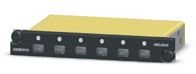
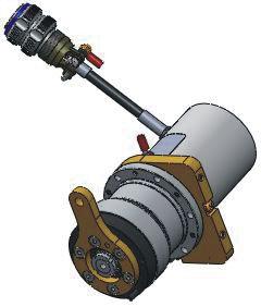
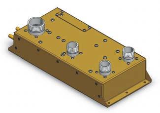
11 1.4 HeliSAS Components The HeliSAS system consists of the following components: Flight Control Computer (FCC). HeliSAS Control Panel (HCP) to select and annunciate SAS and autopilot modes (or a SAS On/Off switch to select and annunciation SAS for a SAS- Only configuration). Servo-actuators one each for the pitch and roll axes (2ea for systems utilizing a primary and backup HeliSAS). Attitude Reference source can be one of the following: - An analog panel-mounted gyro horizon indicator. - A digital Attitude Heading Reference System (AHRS) or Air Data Attitude Heading Reference System (ADAHRS). HeliSAS can be interfaced with the following avionics and instruments. GPS navigation receiver The autopilot will track the active course, fly procedure turns and holding patterns, and fly LNAV/VNAV approaches. VHF navigation receiver The autopilot will track VOR courses and will fly ILS approaches. Horizontal Situation Indicator (HSI) or a functional equivalent on an Electronic Flight Instrument System (EFIS) display The heading bug on the HSI allows the pilot to select headings for the autopilot to fly while in the HDG mode. The course pointer on the HSI allows the pilot to select the desired course for VOR/ILS tracking while in the NAV mode, and provides visual representation of deviation from the desired path. A directional gyro with heading bug is available as an alternative to the HSI or EFIS. While the directional gyro provides a less expensive and lighter alternative, it does not allow the autopilot to be used for VOR/ILS tracking. 1.5 System Description The basic SAS consists of two electromechanical servo-actuators, a flight control computer, HeliSAS Control Panel (HCP) for autopilot mode selection, a panelmounted attitude indicator or an attitude heading reference system (AHRS), two control buttons on the cyclic stick, and interconnecting cables. One servo-actuator controls pitch and the other servo-actuator controls roll. The servo-actuators are connected to the cyclic through electromagnetic clutches. An optional BeepTrim four-way momentary switch on the cyclic can be used to modify the attitude target in SAS mode on certain models th Ed. Jun 10, 16
 and Robinson R44/66")

12 The cyclic-mounted buttons as installed on a Bell 407 (left) and Robinson R44/66 (right) cyclic are shown in Fig Fig Cyclic Buttons 4th Ed. Jun 10,
13 The Force Trim Release (FTR) button is used to reset the trim pitch and roll attitude when in SAS mode. Holding the trim button for more than 1.25 seconds engages the SAS as long as the system is in standby mode and not configured for use with a backup HeliSAS. The AP DISC/OFF button allows disengagement with hands on controls. The optional beep trim switch may be installed in addition to the FTR button, and allows the pilot to proportionally modify the trim pitch and roll attitudes in SAS mode. This is a four-way momentary switch on the cyclic grip. Holding the switch aft results in a steadily increasing change in trim pitch attitude (nose up). Pushing it forward results in a steadily decreasing trim pitch attitude (nose-down). Holding it right causes the trim roll attitude to increase right wing down, and holding it left causes the trim roll attitude to increase in a left-wing down direction. The maximum trim attitudes that may be achieved with beep trim are the same as for the FTR button. The HeliSAS Control Panel (HCP) is used to engage the SAS and/or autopilot modes. Available modes may include altitude hold, heading hold, navigation signal tracking, speed hold, and approach guidance depending on installed avionics and version HeliSAS Flight Control Computer. The far left button controls the basic SAS. The SAS must be engaged prior to engaging an autopilot mode. The NAV mode will track whatever course is active on the HSI or EFIS display (VLOC or GPS). The system automatically adjusts its gain to account for the tighter tracking required for instrument approaches, so there is no need for the Approach (APR) button found on many autopilots. A mode may be disengaged by pressing the associated button on the HCP. If any of the autopilot modes are armed or active, pressing the cyclic-mounted AP DISC/OFF button once disengages all autopilot modes but leaves the underlying SAS mode active. If the cyclic-mounted AP DISC/OFF button is kept pressed for more than 1.25 seconds after the autopilot disengages or if it is pressed without any autopilot modes being armed or active, the SAS mode will disengage leaving the HeliSAS in the standby mode (i.e., SAS is ready for engagement) th Ed. Jun 10, 16
14 A diagram showing the interaction of components of HeliSAS is shown in Figure 1-2. Pitot Static System (Analog) Attitude Gyro (Analog) Horizontal Situational Indic ato r (Analog) Directional Gyro (Analog) AHRS (ARINC 429) On/Off SAS Switch (Discrete In/Out) Main CPU - Built In Test - SAS and Vertical and Lateral Autopilot Modes - Safety Monitors - Servo Clutch Engage/Disengage Logic - Servo Motor Commands that drive the servos Maintenance Port (RS232) Audio Panel HCP (RS-422 Serial) Pitch Servo Roll Servo ST-360 Altitude Pre- Selector RS232 RS232 OR Three Axis Body Rate Gyros Triaxial Accelerometer Altitude Transducer Airspeed Transducer Monitor CPU - Built In Test - SAS and Vertical and Lateral Autopilot Modes - Safety Monitors - Servo Clutch Engage/Disengage Logic - Servo Motor Commands that do not drive the servos GPS Sensor (ARINC 429) Analog Analog EFIS (ARINC 429) Analog Analog OR ADC (ARINC 429) Analog OR RS422 OR ARINC Flight Control Computer Discrete Inputs (Analog) Analog Analog Analog ARINC Fig HeliSAS System Diagram 4th Ed. Jun 10,
15 1.6 Safety Monitors Safety monitors automatically disengage the system if a malfunction is detected. Four beeps sound in the headset at 600 Hz anytime the system is disengaged either automatically or by the pilot. The four beep sequence also occurs once during each start-up self-test. The pilot must be prepared to takeover immediately following a system disconnect. Loss of a valid navigation signal during NAV tracking will cause the associated autopilot mode to disconnect. For example, loss of a VOR signal will result in disconnect of the NAV mode, leaving lateral control in SAS mode (maintains roll attitude level). If engaged, altitude hold would remain engaged. Failure of the altitude sensor will cause ALT to disconnect, and longitudinal control will revert to SAS (holds current pitch attitude). If engaged, HDG or NAV would remain engaged. An autopilot mode disengagement that is not commanded by the pilot is indicated by a single 600 Hz beep in the headset. Intentional disengagement of an autopilot mode does not trigger a headset beep th Ed. Jun 10, 16
16 SECTION 2 PRE-FLIGHT PROCEDURES 4th. Jun 10,
17 Page Intentionally Blank 2-2 4th Ed. Jun 10, 16
18 2.1 Pre-Flight Procedures The SAS will be in standby without any pilot action as it is wired to the avionics bus without an on-off switch. This is done so that the SAS can be engaged immediately if needed. The indicator lights will flash as soon as the master switch is turned on. This indicates that the FCC is initializing. When the lights stop flashing and a steady white SAS indicator light is displayed, the system is in standby mode indicating that the SAS may then be engaged by the pilot. Note: If using Ver52 as a SAS-Only (no HCP, just SAS-On/Off switch), the SAS-On/ Off annunciators do not flash during initialization; they will be dark until the initialization is complete, and then the SAS-Off annunciator light will become white indicating the SAS is in standby mode. If an AHRS/ADAHRS is used as the pitch and roll attitude sensor, the system will enter standby after the alignment process is complete. If the analog panel-mounted mechanical attitude gyro (e.g. Castleberry) is used, the system will not enter standby mode unless the attitude gyro bank angle is less than 6. If the attitude gyro bank angle is greater than 6, pulling and releasing the gyro caging knob will expedite the boot up process. 4th. Jun 10,
19 Once the system enters standby mode, perform the preflight actions shown in Table 2-1. For each action, verify the corresponding response where applicable. ACTION 1. Immediately after starting engine or immediately after powering the helicopter. RESPONSE Note: Alternate white and green flashing annunciator light(s) on the HCP. 2. Adjust cyclic friction to full off. Note: Essentially no resisting force on cyclic. 3. Engage SAS after lights stop flashing and SAS annunciator is white. Note: The SAS LED is a steady green. 4. Displace the cyclic slightly in pitch and release. Note: Resisting force and that cyclic returns to trim position when released. 5. Displace the cyclic slightly in roll and release. Note: Resisting force and that cyclic returns to trim position when released. 6. Depress and hold the trim button and move the cyclic in pitch and roll. Note: Very low resisting force. 7. Depress AP DISC/OFF button on cyclic. Note: 4 beeps in the headset and that the SAS annunciator turns white. 8. Move cyclic in pitch and roll. Note: Lack of any resisting force. Table 2-1. Power-Up Test 2-4 4th Ed. Jun 10, 16
20 SECTION 3 NORMAL IN-FLIGHT PROCEDURES - SAS 4th Ed. Jun 10,
21 Page Intentionally Blank 3-2 4th Ed. Jun 10, 16
22 3.1 Normal Operating Procedures - SAS Genesys Aerosystems Trim When the SAS is initially engaged, it will maintain the current rotorcraft attitude. The system will not trim to attitudes greater than those defined in the configuration settings. Ver51 and Lower Configurations: - Standard: 6 nose-down pitch, 11 nose-up pitch, and ±5 bank - R44/66: 6 nose-down, 11 nose-up, and ±10 bank - EC130: 10 nose-down, 11 nose-up, and ±5 bank - EC130T2: 10 nose-down, 11 nose-up, and ±10 bank Ver52 and Up Configurations: - Standard: 10 nose-down, 11 nose-up, or and 10 bank If the FTR button is activated (pressed and released) outside these limits while SAS is engaged, the system will return to the closest limit. For example, if the FTR is pressed and released at a 20 bank angle and the cyclic is released, the helicopter will achieve a 10 bank (EC130T2 config) in the same direction. If the SAS is engaged from standby (SAS light white) when the pitch attitude is outside a range of pitch attitude between -10 and +15, or roll attitude of ±6, it will recover to a level attitude. This is intended to serve as a panic button in the event the pilot needs to quickly establish level attitude. The proper technique for flying with the SAS is to fly through the SAS to achieve the desired attitude and activate the FTR. Activation of the FTR refers to a press and release of the button on the cyclic. Activation of the FTR will remove the need to apply force on the cyclic grip and the helicopter will hold the attitude that existed when the trim button is released. Workload will be significantly reduced if the FTR is activated any time there is residual force on the cyclic. It is best to avoid holding the FTR button down while trying to establish a trimmed attitude as this negates the stabilization provided by the SAS. It is better to fly through the SAS and activate the FTR when the desired attitude is achieved. With the SAS in standby mode, pushing and holding the trim button for 1.25 seconds will engage the SAS. Note: This feature is not applicable to a HeliSAS configuration using a backup HeliSAS (available in Ver52 and up). 4th Ed. Jun 10,
23 3.2 Recommended Pilot Technique with SAS HeliSAS uses very small movements of the cyclic to perform its stabilizing function. If the pilot holds the cyclic grip very tightly, the stabilizing action could be inhibited. Proper technique requires that the cyclic grip be held loosely so that cyclic can move slightly within the pilot s hand to allow HeliSAS to compensate for helicopter instability. This is especially true in hover. Never use cyclic friction with the SAS or autopilot engaged. Cyclic friction will inhibit the ability of the system to stabilize the helicopter. The cyclic friction must be all the way off when HeliSAS is engaged. Without SAS the hydraulic controls result in no force feedback to the pilot. The SAS provides a force gradient that acts like a centering spring. This is often referred to as a force feel system. When maneuvering with the SAS engaged, the pilot will feel some resistance on the controls. This is referred to as flying through the system. It is possible to accomplish all normal maneuvering both in low speed and hover and up-and-away by flying through the system. As airspeed changes the force on the cyclic required to hold a given attitude changes. It is recommended that you activate the FTR button to remove residual force from the cyclic. Trimming reduces pilot workload considerably. Note: When using a Ver51 or lower FCC, FTR must be repeatedly pressed to re-trim the cyclic and hold a commanded attitude throughout airspeed changes; however, when using a Ver52 FCC, HeliSAS will automatically compensate for the needed cyclic trim throughout speed changes and hold the commanded attitude th Ed. Jun 10, 16
24 3.3 Closely Monitor the Controls The SAS is intended to enhance safety by reducing pilot workload. It is not a substitute for adequate pilot skill nor does it relieve the pilot of the responsibility to maintain adequate outside visual reference. With HeliSAS engaged, it is possible to fly for periods without touching the cyclic. This significantly reduces pilot workload and therefore, improves safety as long as the pilot remains aware that the helicopter is inherently unstable. A disengagement of the SAS due to a failure may result in a rapid roll or pitch excursion that requires immediate pilot takeover to avoid dangerous attitudes. The divergence following a HeliSAS disengagement is significantly more rapid for helicopters with a semi-rigid rotor system, especially at higher airspeeds (e.g., 120 kts and greater). Such helicopters are fitted with a second independent backup HeliSAS system. If the aircraft is equipped with such a backup HeliSAS (applicable to Ver52 and up), the backup system will automatically engage in SAS mode and hold the attitude that was present at the moment the primary system was disengaged, however, as long as the backup system is the only stabilization system available, the pilot should continue to operate with a hand on the controls. Other events that require immediate takeover are engine or drive train failures or a hydraulic system failure. It is required that the pilot have a hand on the cyclic below 44 KIAS when operating in close proximity to the terrain. It is recommended that the pilot have a hand on the controls at airspeeds near and above V NE. At low airspeeds near the ground this is simply a matter of good practice. At high airspeeds, this recommendation is made because a system failure is much more critical near redline. 3.4 Liftoff and Hover Once all preflight checks are done, engage the SAS and verify that the SAS annunciator light is green. With the trim button held down make cyclic adjustments as the helicopter becomes light on the skids. Once the proper cyclic position has been achieved, release the trim button and lift into a hover. Make needed cyclic adjustments to hold the hover position, and then activate the FTR to eliminate any residual force on the cyclic. Maximum benefit will be obtained from the SAS if the cyclic grip is held loosely. This allows the SAS to provide stabilization for hover with the pilot applying small and infrequent inputs to correct for slight changes in wind velocity and direction. In light winds, it is possible to hover with no inputs to the cyclic. 3.5 Acceleration from Hover Accelerate from hover normally, activating the FTR as necessary to compensate for changing forces on the cyclic due to increasing airspeed when using a Ver51 and lower FCC. When using a Ver52 and higher FCC, HeliSAS will automatically compensate for the needed cyclic trim throughout speed changes and hold the commanded attitude, so activating the FTR only needs to be used to set a new commanded/desired attitude. 4th Ed. Jun 10,
25 3.6 Cruise It is possible to cruise in SAS mode with no inputs to the cyclic once the helicopter is properly trimmed. Autopilot modes may be engaged at airspeeds greater than 44 kts and less than V NE. 3.7 Deceleration to Hover Accomplish the deceleration to hover normally by flying through the system and activating the FTR as necessary. If one or more autopilot modes are engaged, they will automatically disengage as the airspeed decreases below 44 kts. This will be accompanied by a single 600 Hz beep in the headset. 3.8 Landing Establish a stable hover by flying through the SAS. Activate the FTR to establish the trimmed cyclic position and helicopter hover attitude. Use the collective control normally to accomplish a vertical descent and touchdown. Workload is minimized if only small occasional cyclic inputs are made to eliminate drift during the vertical descent. Disengage the SAS and set the cyclic friction after the helicopter is on the ground. It is acceptable to allow the SAS to be engaged indefinitely while on the ground, however when using a Ver52 and higher FCC without a discrete input from a skid sensor wired to the FCC, it is recommended the system be disengaged to standby mode or that the pilot press FTR once more after established on the ground to sync the commanded attitude with the aircraft attitude on the ground in order to avoid cyclic drift. 3.9 Disengage SAS/Autopilot The SAS is normally disengaged by pressing the AP DISC/OFF button on the cyclic grip, the SAS button on the HCP, or the SAS On/Off switch on the instrument panel (if installed as a SAS-Only system). It is also possible to disengage the SAS by pulling the SAS circuit breaker. If one or more autopilot modes are engaged, pressing the AP DISC/OFF button causes the autopilot modes to disengage. A second press of the AP DISC/OFF button disengages the SAS. With one or more autopilot modes engaged, both the SAS and autopilot may be disengaged by holding the AP DISC/OFF button down for more than 1.25 seconds. A disengagement of the SAS will always be accompanied by four 600 Hz beeps in the headset. The pilot s hand must be on the cyclic when the SAS is disengaged. This is necessary because the helicopter is inherently unstable and therefore may diverge from steady flight when the SAS is disengaged th Ed. Jun 10, 16
26 SECTION 4 NON-NORMAL PROCEDURES - SAS FAILURES 4th Ed. Jun 10,
27 Page Intentionally Blank 4-2 4th Ed. Jun 10, 16
28 4.1 SAS Failures and Automatic Disengagement The SAS has been designed to be very reliable. However, any system can encounter a hardware failure and safe operation dictates that the pilot become familiar with actions to take in the event of such failures. HeliSAS is a fail passive system meaning that it will automatically disengage prior to any significant cyclic motion when system safety monitors sense a failure. This is accompanied by an aural warning of 4 beeps in the headset. Testing has shown that cyclic motions following system failures are very small. Nonetheless, even small cyclic motions can result in moderately rapid pitch or roll rates. This means that the pilot must closely monitor the cyclic control and helicopter attitude and be ready to takeover immediately. If the pilot s hand is on the cyclic at the point of failure, the only cue will be that a small force may be felt that cannot be alleviated with the FTR. In that case simply continue to fly through the system and disengage when practical using the AP DISC/OFF button on the cyclic or the SAS button on the panel. If the cyclic exhibits abrupt or erratic motion, or exhibits a large resisting force, fly through the system to retain control and disengage the SAS as soon as practical. Note that small cyclic motions are normal, especially when flying in turbulence. If the SAS automatically disengages, it is acceptable to attempt to re-engage as long as the system is in standby (SAS on HCP or the SAS On/Off switch on the instrument panel is white). A false trip of the safety monitors may occur if the attitude gyro is not fully erected after engine start and an aggressive departure is accomplished. This may occur if the period between startup and liftoff is short (order of less than 3 minutes). If that occurs, simply re-engage the SAS using the FTR button or the SAS button on the HCP. 4.2 Autorotation It is acceptable to accomplish autorotations from any flight condition to touchdown with the SAS engaged. For autorotations from forward flight, it will be necessary to apply aft force on the cyclic as the collective is rapidly lowered to maintain rotor RPM. Once the proper pitch attitude is achieved, activate the FTR. The SAS will then hold that attitude with essentially no pilot inputs to the cyclic. Accomplish the flare and touchdown normally by flying through the SAS. 4.3 Hydraulic System Failure The SAS will not function properly without functioning hydraulic flight controls. In the event of a hydraulic system failure, disengage the SAS. 4.4 Icing The SAS or autopilot may not function properly in the extremely unusual situation where there is significant ice buildup on the servos. Pilot may notice a very slight increase in cyclic force, even with the SAS disengaged. This is due to the ice buildup on the servo-actuators causing the clutch to be ineffective. The force to backdrive the servo-actuators is less than one pound. 4th Ed. Jun 10,
29 Page Intentionally Blank 4-4 4th Ed. Jun 10, 16
30 SECTION 5 NORMAL IN-FLIGHT PROCEDURES - AUTOPILOT 4th Ed. Jun 10,
31 Page Intentionally Blank 5-2 4th Ed. Jun 10, 16
32 Autopilot modes are selected on the HeliSAS Control Panel in Fig. 5-1 and Fig Fig HeliSAS Control Panel (HCP) with BC Button (Ver51) Fig HeliSAS Control Panel (HCP) with SPD Button (Ver52) The LEDs above the mode select buttons indicate the status of the modes as follows: LED is dark Mode is not engaged or armed. LED is white Autopilot mode is armed or SAS is in standby. LED is green Mode is engaged. 4th Ed. Jun 10,
33 5.1 Heading (HDG) Mode Set the Heading Bug to the desired heading on the HSI or EFIS and then press the HDG mode button on the HCP to engage the heading mode. The LED above the HDG button will illuminate green when HDG is engaged. The helicopter will turn to selected headings with a maximum bank angle of 20. When making heading changes, it is acceptable to fly-through the system to achieve larger or smaller bank angles. If a heading bug source is not available (e.g., HSI not installed) and a GPS navigation radio is receiving a valid signal, HeliSAS will hold the current GPSderived track angle when the HDG mode is selected. The commanded track can be resynchronized by activating the trim button on the cyclic grip at the desired track angle. 5.2 Navigation (NAV) Mode - VLOC NAV tracks the course on the HSI if the CDI mode on the navigation receiver is VLOC and tracks the active GPS course if the CDI mode is GPS. If an HSI (or functional equivalent on an EFIS display) is not installed, NAV will only track the active GPS course and this section does not apply If HDG is Not Active - Fixed Intercept Angle Select the VOR or ILS frequency on the navigation receiver and set the selected course arrow on the HSI to the desired course. Press the NAV mode button on the HCP to engage the navigation mode. If the Course Deviation Indicator (CDI) deflection and rate indicate that the helicopter is on the selected course or is predicted to cross the selected course in 15 seconds or less, the NAV annunciation on the HCP will illuminate green to indicate that NAV has captured and is tracking the course. If the CDI deflection and rate indicate that the estimated time to cross the selected course is greater than 15 seconds, the autopilot will establish the helicopter on a 45 intercept angle relative to the selected course. In this case the NAV annunciation will be white, indicating that NAV is armed. When the CDI deflection is less than 75% full scale and the estimated time to cross the selected course is greater than 15 seconds and less than 90 seconds, the intercept angle is reduced to 30. Due to limitations on the analog course error signal received from the HSI, the helicopter must be tracking within 90 of the selected course in order to establish the proper intercept angle when NAV is selected. This limitation does not apply when the navigation receiver is set to GPS. As the helicopter approaches the selected course, the autopilot senses the deflection rate of the CDI as it approaches center and initiates a turn to capture the course. This occurs when the lateral deviation is less than 25% full scale and tracking within 15 of the final approach course, or the estimated time to cross the selected course is 15 seconds or less th Ed. Jun 10, 16
34 At course capture, the NAV annunciation transitions from white to green. The bank angle at course capture depends on the distance from the VOR, or final approach fix for a localizer, but is limited to 20. For a VOR course the bank angle is limited to 10, 30 seconds after the autopilot captures the selected course (annunciator changes from white to green). For a localizer course the bank angle is limited to 15, 30 seconds after capture. The autopilot automatically adjusts the tracking gains depending on whether the course is a VOR or localizer. If an ILS or localizer approach is programmed into the GPS, the GPS navigation radio may automatically switch from GPS to VLOC. If the NAV mode is active, the autopilot will automatically transition from tracking an active GPS course to the selected course that is set on the HSI. The autopilot will remain in NAV mode during this transition. There may be a slight lateral transient at this transition if the localizer course does not exactly overlay the final approach course defined by the GPS. If NAV is in track mode (green annunciation) and the course deviation subsequently increases to full scale for 30 seconds, the autopilot will turn to recapture the selected course at an angle of 45 or 30 depending the estimated time to recapture as noted above. This might occur if the pilot selects a new course Pilot Selected Intercept Angle To select an intercept angle other than 45, set the heading bug on the HSI to achieve the desired intercept angle. Set the selected course arrow on the HSI to the desired course. Select HDG and then select NAV on the HCP. This will cause the HDG annunciation to be green and the NAV annunciation to be white (armed). As the helicopter approaches the selected course, the autopilot senses the corresponding rate at which the CDI needle deflection approaches center and initiates a turn to capture the course. This will occur when the lateral deviation is less than 75% full scale and the estimated time to cross the selected course is 15 seconds or less. At course capture, the NAV annunciation transitions from white to green, and the HDG annunciation transitions from green to dark (off). The bank angle at course capture depends on the distance from the VOR, or final approach fix for a localizer, and the selected intercept angle, but is limited Backcourse (BC) Mode (Applicable to Ver51 and Lower) Backcourse Mode (BC) is identical to NAV but with reverse sensing for backcourse approaches. The course on the CDI should be set to the inbound front course in this mode (tail of HSI course needle points toward runway). BC mode only applies if the navigation receiver is set to VLOC. 4th Ed. Jun 10,
35 5.4 Navigation (NAV) Mode - GPS NAV mode requires that an active course has been programmed into the GPS as a flight planned route, instrument approach procedure, or a direct-to a waypoint. The navigation receiver must be selected to GPS. The autopilot does not use the selected course on the HSI for this mode. If an HSI is installed, it is useful to set the selected course arrow to the desired track angle to maintain situational awareness. However, this has no effect on autopilot performance. The selected course on an EFIS display will generally auto-slew to the desire GPS course. The autopilot will follow the GPS roll steering through holding patterns and published course reversals on instrument approach procedures. This feature is only available if the GPS receiver is WAAS capable, and if roll steering is valid Preprogrammed Intercept Angle Ensure that HDG is not engaged and press the NAV mode button on the HCP to engage the navigation mode. The NAV mode will engage (green annunciation on HCP) and the autopilot will follow the GPS roll steering commands to capture and track the active course. If the helicopter is offset from the selected leg, the intercept angle will be set by the roll-steering logic in the navigation receiver. The bank angle is limited to 20. If roll steering is not valid, the internal control laws will capture the selected course at a 45 angle. This mode of control does not require an HSI or DG Pilot Selected Intercept Angle To select an intercept angle to an active GPS course, set the heading bug on the HSI to achieve the desired intercept angle. Select HDG and then select NAV on the HCP. This will cause the HDG annunciation to be green and the NAV annunciation to be white (armed). This is especially useful if being vectored to final for an instrument approach procedure. As the helicopter approaches the selected course, NAV will transition from armed (white) to active (green) and HDG will disengage (dark). The autopilot will smoothly capture and track the active course. The bank angle is limited to 20. Note that capture will not occur if the selected heading does not cause the helicopter to intercept the active course. If an HSI or DG is not installed, it is still possible to select an intercept angle using the HDG mode. Select HDG and then NAV as is done when a DG or HSI in installed. HDG will annunciate as green (active) and NAV as white (armed). With no heading source, the autopilot will hold the current GPS-derived track angle. The desired track to intercept the active course can be achieved by flying through the autopilot with lateral cyclic and activating the FTR button on the cyclic grip to reset the reference track angle. As the helicopter approaches the selected course, NAV will transition from armed (white) to active (green) and HDG will disengage (dark). The autopilot will smoothly capture and track the active course th Ed. Jun 10, 16
36 5.4.3 Course Reversals and Holding Patterns The autopilot will follow the GPS roll steering commands through holding patterns and published course reversals as long as GPS roll steering is valid. If GPS roll steering is not valid, and for non-waas GPS receivers, it will be necessary to accomplish these procedures in HDG mode. 5.5 Speed (SPD) Hold Mode (Applicable to Ver52 and Higher) The SPD mode provides pitch attitude commands to hold a selected VS (Vertical Speed) or IAS (Indicated Airspeed). It can be a stand-alone mode or with altitude pre-select (ALT armed), depending on the following: A single press of the SPD button holds the Indicated Airspeed that exists when the SPD mode is selected. The reference speed may be reset at any time by pressing and releasing the FTR button on the cyclic grip. This is the stand-alone SPD mode indicated by a green SPD light. Pressing the ALT button on the HCP will cause ALT to engage and SPD to disengage. After selecting VS and ALT targets (either via a digital source such as an EFIS or an analog VS bug from an S-TEC preselector or similar device), pressing the SPD and ALT buttons simultaneously will set SPD (green) with ALT armed (white). This mode holds the commanded/selected Vertical Speed until the selected altitude is reached. After selecting IAS and ALT targets (via a digital source such as an EFIS), pressing the SPD and ALT buttons simultaneously will set SPD (green) with ALT armed (white). This hold the commanded/selected Indicated Airspeed until the selected altitude is reached. If there are no VS or IAS targets available and no ALT target available, the Dual SPD/ALT button press will not function. Only stand-alone SPD (holds current airspeed with single press of SPD button) will be available. When in dual SPD (green) and ALT (white), ALT stays armed until the selected altitude is reached, at which point, ALT will become active (green) and SPD will go off (dark). If both VS and IAS targets are present at the same time, the VS target is the priority. 5.6 Altitude (ALT) Hold Altitude Hold Mode may be engaged at any time above 200ft off the ground and is annunciated by a green LED above the ALT button. It is not possible to arm the ALT mode using a Ver51 FCC, however arming ALT is possible if using a Ver52 FCC with a valid pre-selected altitude as described above in Section 5.5 (Speed Mode). ALT holds barometric altitude at the altitude where the mode is engaged. If the helicopter is in a climb or descent, when ALT is engaged, it will gently initiate a pitch rate to stop the rate of climb or descent. It will then command a rate of climb or descent to return to the altitude where the mode was engaged. Because of lags in the altimeter, the helicopter may not return to the exact indicated altitude where ALT was engaged, especially if the climb or descent rate is large. The target altitude may be reset by manually flying through the autopilot to the desired altitude and activating the FTR button. 4th Ed. Jun 10,
37 The autopilot uses pitch attitude to control altitude so airspeed will vary with power setting. To accomplish an airspeed change while ALT is engaged, slowly move the collective to the new power setting. A rapid change in collective will cause the helicopter to deviate from the target altitude. That is because collective is a powerful control of vertical rate and it is not possible for the autopilot to counter rapid power changes with pitch attitude. Nonetheless, the autopilot will gradually return to the reference altitude, albeit at a different airspeed. When following ground references at low altitude, it is useful to engage ALT and leave the roll axis in SAS mode. This allows following of ground references by flying through the lateral SAS, and allowing ALT to hold altitude. 5.7 Vertical (VRT) Mode The Vertical Navigation Mode (VRT) allows the autopilot to track an ILS glideslope or GPS VNAV, LNAV + V, or LPV glidepath. VRT must be armed prior to intercepting the glidepath. An armed VRT mode is indicated by a white LED. NAV must be armed or active and the GPS must be in the approach mode (e.g., LPV) for VRT to arm. If NAV is not armed or active (annunciation white or green) or the GPS has not transitioned to an approach mode, pushing the VRT button will have no effect (VRT annunciation will remain dark). It is necessary to wait for the GPS to transition from TERM to an approach mode such as LPV or LNAV/VNAV to arm VRT. SPD mode cannot remain active with VRT armed. Pressing VRT while in SPD mode, will activate ALT (green) and arm VRT (white) until glidepath intercept. For an ILS approach the navigation receiver must be selected to VLOC, and a valid ILS signal must be present to arm VRT. An HSI or EFIS must be installed for the autopilot to accomplish a coupled ILS approach. For GPS approaches, the autopilot will track the VNAV glidepath without an HSI, albeit with no visual indication of the glideslope error. De-selecting and reselecting ALT while VRT is armed will cause VRT to dis-arm. It is therefore necessary to re-arm VRT if ALT is cycled while setting up for an ILS or VNAV approach. VRT will switch from armed to active (LED from white to green) at glidepath intercept. This transition can occur with the pitch axis in the SAS or ALT modes. If in ALT mode, ALT will transition from green to dark when VRT becomes active. The recommend technique is to slowly reduce collective prior to glidepath intercept to a power setting that will cause the autopilot to track the glideslope at the desired airspeed. It is important to minimize changes in collective during glideslope tracking as this can result in excursions from the glideslope. If collective changes are necessary to change airspeed, make them very slowly. With collective held fixed, airspeed will change to maintain glideslope in the presence of vertical atmospheric disturbances th Ed. Jun 10, 16
38 Glideslope tracking will become less accurate at low airspeeds because the helicopter is approaching the backside of the power required curve. The VRT mode will automatically disengage if the airspeed decreases below 44 kts. For ILS approaches the autopilot control laws use GPS groundspeed to enhance ILS glideslope tracking. If a GPS receiver is not available, VRT will still function, but glideslope tracking will be less accurate. It is recommended that the GPS overlay be loaded for ILS and localizer approaches. While this is not essential, it serves two useful purposes. First situational awareness is enhanced by having the final approach course displayed on the moving map. Second, when the GPS overlay is active, the autopilot control laws use GPS-derived track angle to enhance localizer intercept and tracking, especially in crosswinds. At minimums, disengage the autopilot by pressing the red AP DISC/OFF button on the cyclic grip and accomplish the deceleration in SAS mode. 5.8 Missed Approach VLOC (ILS or VOR Approach) At the missed approach point accomplish the following: 1. Add power to arrest rate of descent and change the selected navigation source from VLOC to GPS As long as the GPS overlay is active, this causes the autopilot to track the extended runway centerline by remaining in NAV mode. 2. VRT will disengage when the CDI is changed from VLOC to GPS and the pitch mode will change from VRT to SAS. This will be accompanied by a one second beep in the headset. The one second beep occurs because VRT disengaged without pressing the VRT button on the HCP. 3. Add power and pitch to the desired climb attitude and press and release the FTR button. If using a Ver52 or higher FCC, SPD mode can be used to accomplish the climb-out at a desired IAS or VS rather than using the pitch hold portion of SAS. 4. Resume waypoint sequencing on the navigation receiver. The autopilot will remain in NAV mode and turn to intercept the published missed approach course. If the missed approach procedure requires a heading, set the heading bug on the HSI and engage HDG. 5. The autopilot will follow the GPS steering commands to accomplish the missed approach procedure including a holding pattern. This procedure only works if the ILS overlay is programmed into the GPS. If that is not the case, disengage the autopilot at minimums and complete the missed approach using SAS, HDG, and ALT. 4th Ed. Jun 10,
39 5.8.2 GPS (LPV, LNAV/VNAV, or LNAV + V Approach) At the missed approach point, add power to arrest rate of descent and disengage VRT by pressing the VRT button on the HCP. The lateral autopilot mode will remain NAV, and the pitch mode will change from VRT to SAS. Accomplish steps 3 through 5 as described in Section Alternatively, it is possible to fly through the autopilot in pitch and VRT will disable automatically (becomes invalid after passing a point approximately 1000 feet past the runway threshold). An alternative missed approach procedure is to press the AP DISC/OFF button on the cyclic at the missed approach point, and manually fly the missed approach in SAS mode th Ed. Jun 10, 16
40 SECTION 6 GLOSSARY 4th Ed. Jun 10,
41 Page Intentionally Blank 6-2 4th Ed. Jun 10, 16
42 Term AHRS ALT AP AP DISC APP BC CDI DG EFIS FAA FCC FTR GPS HCP HDG HSI HZ IAF IFR ILS KIAS KTS LNAV LNAV+V LPV NAV PN POH RFM RFMS RPM SAS SPD STC VHF VLOC VNAV VOR VRT WAAS Genesys Aerosystems Meaning Attitude Heading Reference System Altitude Hold Autopilot Autopilot Disconnect Approach Back Course Course Deviation Indicator Directional Gyro Electronic Flight Instrument System Federal Aviation Administration Flight Control Computer Force Trim Release Global Positioning System HeliSAS Control Panel Heading Horizontal Situation Indicator Hertz Initial Approach Fix Instrument Flight Rules Instrument Landing System Knots Indicated Airspeed Knots Lateral Navigation Lateral Navigation with Advisory Vertical Guidance Lateral Precision with Vertical Guidance Navigation Part Number Pilot's Operating Handbook Rotorcraft Flight Manual Rotorcraft Flight Manual Supplement Revolutions Per Minute Stability Augumentation System Speed Mode Supplement Type Certificate Very High Frequency VOR or LOC Frequency Vertical Navigation Very High Frequency Omnidirectional Radio Range Vertical Mode Wide Area Augmentation System 4th Ed. Jun 10,
43 Page Intentionally Blank 6-4 4th Ed. Jun 10, 16

44 Information contained in this document is subject to change without notice Genesys Aerosystems. All rights reserved. Printed in the United States of America. Genesys Aerosystems and the HeliSAS logo are registered trademarks of Genesys Aerosystems. Notice: Contact S-TEC Customer Support at for a Service Repair Order (SRO) number prior to the return of any component for any reason. One S TEC Way Municipal Airport Mineral Wells, TX Tel: Fax: S TEC PN 87295
Pilot s Operating Handbook
 Pilot s Operating Handbook List of Effective Pages * Asterisk indicates pages changed, added, or deleted by current revision. Page No. Issue Retain this record in front of handbook. Upon receipt of a Record
S-Tec System 55 Autopilot
 Cirrus Design Section 9 Pilot s Operating Handbook and FAA Approved Airplane Flight Manual Supplement for S-Tec System 55 Autopilot When the S-Tec System 55 Autopilot is installed in the Cirrus Design,
2100 Autopilot Programmer/Computer PN Software Mod Code L or Later WAAS Capable Pilot s Operating Handbook
 2100 Autopilot Programmer/Computer PN 01304 Software Mod Code L or Later WAAS Capable Pilot s Operating Handbook NAV VS 500 ALT 12 5 00 List of Effective Pages * Asterisk indicates pages changed, added,
Cirrus SR20/22 Aircraft with Cirrus Perspective Avionics. Pilot s Operating Handbook
 Cirrus SR20/22 Aircraft with Cirrus Perspective Avionics Pilot s Operating Handbook List of Effective Pages * Asterisk indicates pages changed, added, or deleted by current revision. Page No. Issue Retain
S-TEC. Pilot s Operating Handbook
 S-TEC Pilot s Operating Handbook List of Effective Pages * Asterisk indicates pages changed, added, or deleted by current revision. Retain this record in front of handbook. Upon receipt of a Record of
P/N 135A EASA Approved: June 23, 2011 Section 9 Initial Release Page 1 of 22
 EASA APPROVED AIRPLANE FLIGHT MANUAL SUPPLEMENT FOR S-TEC SYSTEM 30 AUTOPILOT INTEGRATED IN THE LIBERTY XL2 SERIES AIRCRAFT Serial No: Registration No: When installing the S-TEC System 30 Autopilot Integrated
Revision Number Revision Date Insertion Date/Initials 1 st Ed. Oct 26, 00 2nd Ed. Jan 15, 08
 List of Effective Pages * Asterisk indicates pages changed, added, or deleted by current revision. Retain this record in front of handbook. Upon receipt of a Record of Revisions revision, insert changes
S-TEC. Pilot s Operating Handbook
 S-TEC Pilot s Operating Handbook List of Effective Pages * Asterisk indicates pages changed, added, or deleted by current revision. Retain this record in front of handbook. Upon receipt of a Record of
Pilot s Operating Handbook
 Pilot s Operating Handbook List of Effective Pages SA-200 ALTITUDE SELECTOR/ALERTER POH * Asterisk indicates pages changed, added, or deleted by revision. Retain this record in front of handbook. Upon
S-Tec System 55X Autopilot w/ Altitude Selector/Alerter
 Cirrus Design Section 9 Pilot s Operating Handbook and FAA Approved Airplane Flight Manual Supplement For S-Tec System 55X Autopilot w/ Altitude Selector/Alerter When the S-Tec System Fifty Five X (55X)
CESSNA MODEL 182T NAV III AVIONICS OPTION - KAP 140 AUTOPILOT Serials and thru and thru
 CESSNA MODEL 182T NAV III AVIONICS OPTION - Serials 18281228 and 18281318 thru 18281868 and 18281870 thru 18281875 BENDIX/KING KAP 140 2 AXIS AUTOPILOT SERIAL NO. REGISTRATION NO. This supplement must
Discuss: 1. Instrument Flight Checklist
 INST 1 Prerequisites: 1. OFT: Tac 1 2. CBT: Basic Instrument Flight, IFR Navigation I & II Lessons P2 501, P2 502, & P2 503. Discuss: 1. Instrument Flight Checklist NATOPS 13.1.3 Instrument Flight Checklist
Noise Abatement Takeoff 1 Close In Profile
 PF Duties Captain: Advance thrust to 70% N1 (Allow Engines to stabilize) Noise Abatement Takeoff 1 Close In Profile Flaps Increase Speed to Vref 30 +80kts Climb Checklist Push N1 Button to set Takeoff
CHAPTER 4 AUTOMATIC FLIGHT CONTROLS
 CHAPTER 4 AUTOMATIC FLIGHT CONTROLS CONTENTS Page GENERAL... 4-1 SYSTEM DESCRIPTION... 4-4 Lateral Modes... 4-4 Vertical Modes... 4-9 Autopilot Operation... 4-15 CONTROLS AND INDICATIONS... 4-22 Flight
MOONEY AIRPLANE COMPANY, INC. LOUIS SCHREINER FIELD KERRVILLE, TEXAS FAA APPROVED: AIRPLANE FLIGHT MANUAL SUPPLEMENT MOONEY M20M, M20R, M20TN
 MOONEY AIRPLANE COMPANY, INC. LOUIS SCHREINER FIELD KERRVILLE, TEXAS 78028 FAA APPROVED AIRPLANE FLIGHT MANUAL SUPPLEMENT FOR MOONEY WITH S -TEC SYSTEM 55X, TWO AXIS, AUTOPILOT INSTALLED MODEL NO. REG.
PROCEDURES AND PROFILES TABLE OF CONTENTS
 PROCEDURES AND PROFILES 10-1 PROCEDURES AND PROFILES TABLE OF CONTENTS SUBJECT PAGE AUTOFLIGHT NORMS...3 Overview...3 Aircraft Control...3 Control Norms...3 Autothrottle...3 MCP Command Speed Bug...3 FMC
OFFICE HOURS Monday through Friday, 7:30 a.m. to 4:30 p.m., Pacific Time. Lunch hour is 11:30 a.m. to 12:30 p.m.
 Robinson Helicopter Company Phone: (310) 539-0508 2901 Airport Drive Fax: (310) 539-5198 Torrance, California 90505-6115 Web: www.robinsonheli.com United States of America OFFICE HOURS Monday through Friday,
PRIVATE PILOT MANEUVERS Practical Test Standards FAA-S A
 PRIVATE PILOT MANEUVERS Practical Test Standards FAA-S-8081-15A Special Emphasis Areas Examiners shall place special emphasis upon areas of aircraft operation considered critical to flight safety. Among
CIVIL AIR PATROL United States Air Force Auxiliary Cadet Program Directorate. Cessna 172 Maneuvers and Procedures
 CIVIL AIR PATROL United States Air Force Auxiliary Cadet Program Directorate Cessna 172 Maneuvers and Procedures This study guide is designed for the National Flight Academy Ground School. The information
ILS APPROACH WITH A320
 1. Introduction ILS APPROACH WITH A320 This document presents an example of an Instrument landing system (ILS) approach performed with an Airbus 320 at LFBO airport runway 32 left. This document does not
Jabiru J230-SP Section 10
 Jabiru J230-SP Section 10 Section 10 10.1 Introduction This section contains information on the basic flight controls, door operation, and entry and egress, followed by a flight training outline compiled
AIRCRAFT SYSTEMS AUTO FLIGHT - FLIGHT AUGMENTATION
 Intentionally left blank PRELIMINARY PAGES - TABLE OF CONTENTS DSC-22_40-10 General GENERAL... A DSC-22_40-20 Yaw Functions YAW DAMPING...A RUDDER TRIM...B RUDDER TRAVEL LIMITATION...C DSC-22_40-30 Flight
Flight Profiles are designed as a guideline. Power settings are recommended and subject to change based
 MANEUVERS AND PROCEDURES Flight Profiles are designed as a guideline. Power settings are recommended and subject to change based upon actual conditions (i.e. aircraft weight, pressure altitude, icing conditions,
NORMAL TAKEOFF AND CLIMB
 NORMAL TAKEOFF AND CLIMB CROSSWIND TAKEOFF AND CLIMB The normal takeoff is one in which the airplane is headed directly into the wind or the wind is very light, and the takeoff surface is firm with no
CESSNA 172-SP PRIVATE & COMMERCIAL COURSE
 CESSNA 172-SP PRIVATE & COMMERCIAL COURSE University of Dubuque INTENTIONALLY LEFT BLANK Revision 1 Standard Operating Procedures 1 CALLOUTS CONDITION Parking Brake Released After Takeoff Power has been
MANEUVERS GUIDE. Liberty Aerospace 1383 General Aviation Drive Melbourne, FL (800)
") MANEUVERS GUIDE Liberty Aerospace 1383 General Aviation Drive Melbourne, FL 32935 (800) 759-5953 www.libertyaircraft.com Normal/Crosswind Takeoff and Climb 1. Complete the runup and before takeoff checklist.
MANEUVERS GUIDE Liberty Aerospace 1383 General Aviation Drive Melbourne, FL 32935 (800) 759-5953 www.libertyaircraft.com Normal/Crosswind Takeoff and Climb 1. Complete the runup and before takeoff checklist.
B-757 FLEET OPERATIONS
 B-757 FLEET OPERATIONS TRAINING AND STANDARDS Non Precision Approaches 02/28/12 Approach Planning Close The 757 is not capable of intercepting and tracking of VOR or NDB courses or bearings. Therefore
OFFICE HOURS Monday through Friday, 7:30 a.m. to 4:30 p.m., Pacific Time. Lunch hour is 11:30 a.m. to 12:30 p.m.
 Robinson Helicopter Company Phone: (310) 539-0508 2901 Airport Drive Fax: (310) 539-5198 Torrance, California 90505-6115 Web: www.robinsonheli.com United States of America OFFICE HOURS Monday through Friday,
SECTION 1 - GENERAL SECTION 2 - LIMITATIONS SECTION 3 - EMERGENCY PROCEDURES
 Beechcraft Bonanza Models. 35-33,35-A33,35-833,35-C33,35C33A, E33, E33A, E33C, F33, F33A. F33C, G33, A35, 835, C35, D35, E35, F35, G35,35R, H35, 535, K35, M35, N35, P35,S35, V35, V35A, V358,36, A36, A36TC
NORMAL TAKEOFF PILOT TRAINING MANUAL KING AIR 200 SERIES OF AIRCRAFT
 NORMAL TAKEOFF Climb-Out 1. Accelerate to 160 KIAS 2. Landing/Taxi lights: Out 3. Climb Checklist complete 1. 160 KIAS up to 10,000 ft 2. Decrease 2 KIAS per 1,000 ft above 10,000 ft to 130 KIAS at 25,000
I2103 WORKSHEET. Planned Route: Takeoff: KNSE, RWY 32 Altitude: 12,000 Route: RADAR DEPARTURE. Syllabus Notes None
 Planned Route: Takeoff: KNSE, RWY 32 Altitude: 12,000 Route: RADAR DEPARTURE Syllabus Notes None I2103 WORKSHEET Special Syllabus Requirements Proceed direct to homefield using any available NAVAID. Discuss
LNAV & VNAV Integration Review Basics
 HDG / LNAV: LNAV & VNAV Integration Review Basics By Lionel Largmann (Edited and reviewed my anonymous sources) 1. How can we control the lateral guidance of the B747 in-flight? Two primary Roll modes
VI.A-E. Basic Attitude Instrument Flight
 References: FAA-H-8083-3; FAA-8083-3-15 Objectives Key Elements Elements Schedule Equipment IP s Actions SP s Actions Completion Standards The student should develop knowledge of the elements related to
SUPPLEMENT SEPTEMBER 2010 HIGH ALTITUDE TAKEOFF AND LANDING (ABOVE 14,000 FEET PRESSURE ALTITUDE) MODEL AND ON 68FM-S28-00 S28-1
 MODEL AND ON 68FM-S28-00 S28-1") MODEL 680 680-0001 AND ON HIGH ALTITUDE TAKEOFF AND LANDING (ABOVE 14,000 FEET PRESSURE ALTITUDE) COPYRIGHT 2010 CESSNA AIRCRAFT COMPANY WICHITA, KANSAS, USA 15 SEPTEMBER 2010 S28-1 SECTION V - SUPPLEMENTS
MODEL 680 680-0001 AND ON HIGH ALTITUDE TAKEOFF AND LANDING (ABOVE 14,000 FEET PRESSURE ALTITUDE) COPYRIGHT 2010 CESSNA AIRCRAFT COMPANY WICHITA, KANSAS, USA 15 SEPTEMBER 2010 S28-1 SECTION V - SUPPLEMENTS
SECTION 6-16 FLIGHT INSTRUMENTS
 SECTION 6-16 SYSTEMS DESCRIPTION Index Page Pitot-Static System... 6-16-2 Airspeed Indicator... 6-16-4 Vertical Speed Indicator... 6-16-4 Instantaneous Vertical Speed Indicator IVSI (Optional)... 6-16-5
Autothrottle Use with Autopilot Off
 Autothrottle Use with Autopilot Off Bill McKenzie Flight Crew Operations Boeing Commercial Airplanes May 2004 757.1 What Is Pitch Coupling The thrust vector for engines mounted under the wing will cause
Auto.10 Automatic Flight-Description and Operation. General
 Auto.10 Automatic Flight-Description and Operation General The aircraft is equipped with an Automatic Flight System (AFS) for guidance from takeoff to landing. The two AFS flight control computers (FCC)
Page. General Description Controls and Indicators COMPONENTS (Not Used) System Interface /02
 System Interface /02") CHAPTER 3 AUTOMATIC FLIGHT Page TABLE OF CONTENTS 03-00-01/02 DESCRIPTION General 03-10-01 Description 03-10-01 Controls and Indicators 03-10-10 COMPONENTS (Not Used) CONTROLS AND INDICATORS 03-30-01 FUNCTIONAL
CHAPTER 3 AUTOMATIC FLIGHT Page TABLE OF CONTENTS 03-00-01/02 DESCRIPTION General 03-10-01 Description 03-10-01 Controls and Indicators 03-10-10 COMPONENTS (Not Used) CONTROLS AND INDICATORS 03-30-01 FUNCTIONAL
XII.A-D. Basic Attitude Instrument Flight
 References: FAA-H-8083-3; FAA-8083-3-15 Objectives Key Elements Elements Schedule Equipment IP s Actions SP s Actions Completion Standards The student should develop knowledge of the elements related to
SAI-340 Pilot Guide Osuna Road NE Suite 711 Albuquerque, NM Rev 3
 SAI-340 Pilot Guide 306184-00 Rev 3 This document and the information contained herein is the propriety data of SANDIA aerospace Corporation. No part of this document may be transmitted, reproduced, or
Flight Dynamics II (Stability) Prof. Nandan Kumar Sinha Department of Aerospace Engineering Indian Institute of Technology, Madras
 Prof. Nandan Kumar Sinha Department of Aerospace Engineering Indian Institute of Technology, Madras") Flight Dynamics II (Stability) Prof. Nandan Kumar Sinha Department of Aerospace Engineering Indian Institute of Technology, Madras Module No. # 13 Introduction to Aircraft Control Systems Lecture No. #
Flight Dynamics II (Stability) Prof. Nandan Kumar Sinha Department of Aerospace Engineering Indian Institute of Technology, Madras Module No. # 13 Introduction to Aircraft Control Systems Lecture No. #
VIII.A. Straight and Level Flight
 VIII.A. Straight and Level Flight References: FAA-H-8083-3; FAA-H-8083-25 Objectives Key Elements Elements Schedule Equipment IP s Actions SP s Actions Completion Standards The student should develop the
Flying The Boeing Advanced
 Flying The Boeing 727-200 Advanced This section includes Pilot s Operating Handbook and Checklists. The POH section is first, followed by the Checklists. FOM: This section includes performance data on
Advisory Circular (AC)
") Advisory Circular (AC) Stall, Compliance File No. 5009-6-525 AC No. 525-020 RDIMS No. 528401-V3 Issue No. 01 Issuing Branch Aircraft Certification Effective Date 2004-12-01 1.0 INTRODUCTION... 2 1.1 Purpose...
Advisory Circular (AC) Stall, Compliance File No. 5009-6-525 AC No. 525-020 RDIMS No. 528401-V3 Issue No. 01 Issuing Branch Aircraft Certification Effective Date 2004-12-01 1.0 INTRODUCTION... 2 1.1 Purpose...
VIII.A. Straight and Level Flight
 VIII.A. Straight and Level Flight References: FAA-H-8083-3; FAA-H-8083-25 Objectives Key Elements Elements Schedule Equipment IP s Actions SP s Actions Completion Standards The student should develop the
Tecnam Eaglet Standard Operating Procedures and Maneuvers Supplement
 Tecnam Eaglet Standard Operating Procedures and Maneuvers Supplement Normal Takeoff Flaps Take Off Trim set Fuel pump on Check for traffic Line up on white stripe Full power Stick should be located in
Cessna 172R Profiles
 Cessna 172R Profiles TRAFFIC PATTERNS (Verify pattern altitude) Start your first climbing turn within 300' of pattern altitude Enter 45 degree angle to the downwind leg Depart the traffic pattern straight-out,
Single Engine Complex Training Supplement PA28R-201 Piper Arrow III (Spring 2016 Revision)
") Single Engine Complex Training Supplement PA28R-201 Piper Arrow III (Spring 2016 Revision) V-speed Quick Reference V-Speed KIAS Description Airspeed Indicator Marking VSO 55 Stall speed in landing configuration
Single Engine Complex Training Supplement PA28R-201 Piper Arrow III (Spring 2016 Revision) V-speed Quick Reference V-Speed KIAS Description Airspeed Indicator Marking VSO 55 Stall speed in landing configuration
Bonanza/Debonair Pilots
 Bonanza/Debonair Pilots Completing this worksheet is a great way to reinforce the proper speeds for operating your Bonanza or Debonair under varying operating conditions, and to understand the changes
PROCEDURES GUIDE. FLIGHT MANEUVERS for the SPORT PILOT
 Page 1 of 10 PROCEDURES GUIDE FLIGHT MANEUVERS for the SPORT PILOT * Author s Note: Whereas this procedures guide has been written for a specific application, it can easily be modified to fit many different
Climbs, descents, turns, and stalls These are some of the maneuvers you'll practice, and practice, and practice By David Montoya
 Climbs, descents, turns, and stalls These are some of the maneuvers you'll practice, and practice, and practice By David Montoya Air work stalls, steep turns, climbs, descents, slow flight is the one element
Aviation Merit Badge Knowledge Check
 Aviation Merit Badge Knowledge Check Name: Troop: Location: Test Score: Total: Each question is worth 2.5 points. 70% is passing Dan Beard Council Aviation Knowledge Check 1 Question 1: The upward acting
PERFORM A NDB APPROACH [A320]
![PERFORM A NDB APPROACH [A320]](/thumbs/76/73784832.jpg "PERFORM A NDB APPROACH [A320]") 1. Introduction PERFORM A NDB APPROACH [A320] This documentation will illustrate how to perform a NDB approach with an Airbus A320. In addition of NDB approaches, procedures are generally based on conventional
1. Introduction PERFORM A NDB APPROACH [A320] This documentation will illustrate how to perform a NDB approach with an Airbus A320. In addition of NDB approaches, procedures are generally based on conventional
II.E. Airplane Flight Controls
 References: FAA-H-8083-3; FAA-8083-3-25 Objectives Key Elements Elements Schedule Equipment IP s Actions SP s Actions Completion Standards The student should develop knowledge of the elements related to
C-130 Reduction in Directional Stability at Low Dynamic Pressure and High Power Settings
 C-130 Reduction in Directional Stability at Low Dynamic Pressure and High Power Settings The C-130 experiences a marked reduction of directional stability at low dynamic pressures, high power settings,
Flying The Embraer Brasilia (EMB-120)
") Flying The Embraer Brasilia (EMB-120) This section includes Pilot s Operating Handbook and Checklists. The POH section is first, followed by the Checklists. FOM: This section includes performance data
Flying The Embraer Brasilia (EMB-120) This section includes Pilot s Operating Handbook and Checklists. The POH section is first, followed by the Checklists. FOM: This section includes performance data
VI.B. Traffic Patterns
 References: FAA-H-8083-3; FAA-H-8083-25; AC 90-42; AC90-66; AIM Objectives Key Elements Elements Schedule Equipment IP s Actions SP s Actions Completion Standards The student should develop knowledge of
ltitudealert Mini v2.1 Page 1
 ltitudealert Mini Hello, and thank you for purchasing AltitudeAlert! AltitudeAlert Mini is the first altitude preselect and alerting app for the iphone. Please take a moment and review this User Guide
SR22 Airplane Flight Manual (AFM) Temporary Change
 Temporary Change") Cirrus Design TPOH AFM Temporary Change Airplane Flight Manual (AFM) Temporary Change Information in this Temporary Change adds to, supersedes, or deletes information in the basic Pilot s Operating Handbook.
Cirrus Design TPOH AFM Temporary Change Airplane Flight Manual (AFM) Temporary Change Information in this Temporary Change adds to, supersedes, or deletes information in the basic Pilot s Operating Handbook.
Gyroplane questions from Rotorcraft Commercial bank
 Gyroplane questions from Rotorcraft Commercial bank (From Rotorcraft questions that obviously are either gyroplane or not helicopter) FAA Question Number: 5.0.5.8 FAA Knowledge Code: B09 To begin a flight
Straight and Level. Basic Concepts. Figure 1
 Basic Concepts Straight and Level This lesson should start with you asking the student what they did in the last lesson, what do they remember, and determining if they have remembered correctly. We must
Visualized Flight Maneuvers Handbook
 Visualized Flight Maneuvers Handbook For High Wing Aircraft Third Edition For Instructors and Students Aviation Supplies & Academics, Inc. Newcastle, Washington Visualized Flight Maneuvers Handbook for
Front Cover Picture Mark Rasmussen - Fotolia.com
 Flight Maneuvers And Stick and Rudder Skills A complete learn to fly handbook by one of aviation s most knowledgeable and experienced flight instructors Front Cover Picture Mark Rasmussen - Fotolia.com
2. Page 2-13, Figure 2-19, top figure; change the green label Altitude Indicator to Attitude Indicator.
 FAA-H-8083-25A Pilot s Handbook of Aeronautical Knowledge Dated 2009 Errata as of January 21, 2011 1. Page 1-18, right column, 1 st paragraph, last sentence; change the uniform resource locator (URL) to
1811G/H PITOT-STATIC TEST SET
 1811G/H PITOT-STATIC TEST SET USER INSTRUCTION MANUAL M/N: 1811G/H, P/Ns: 101-00165 101-00168 101-00169 Doc. P/N: 56-101-00165_00168_00169 Revision C December 9, 2014 BARFIELD, INC. Corporate Headquarters
STUDY OF LANDING TECHNIQUE DURING VISUAL APPROACH
 24 TH INTERNATIONAL CONGRESS OF THE AERONAUTICAL SCIENCES STUDY OF LANDING TECHNIQUE DURING VISUAL APPROACH Hiroshi TAKAHARA*, Takashi KONDO*, Shinji SUZUKI** *All Nippon Airways Co., LTD., **University
VII.E. Normal and Crosswind Approach and Landing
 References: FAA-H-8083-3; POH/AFM Objectives Key Elements Elements Schedule Equipment IP s Actions SP s Actions Completion Standards The student should be able to perform a normal approach and landing
See the diagrams at the end of this manual for judging position locations.
 Landing Events Penalties General Judges should use airport diagrams, satellite pictures or other means to determine, as accurately as possible, assessments of landing pattern penalties. Judges should be
Attitude Instrument Flying and Aerodynamics
 Attitude Instrument Flying and Aerodynamics 2.1 TURNS 1. An airplane requires a sideward force to make it turn. a. When the airplane is banked, lift (which acts perpendicular to the wingspan) acts not
Cessna 172S Skyhawk Standardization Manual
 Cessna 172S Skyhawk Standardization Manual This manual is to be utilized in conjunction with the manufacturers approved POH/ AFM and the Airplane Flying Handbook (FAA-H-8083-3A). This manual should be
ROTORCRAFT FLIGHT MANUAL SUPPLEMENT. TO THE BELL MODEL UH-1H ROTORCRAFT FLIGHT MANUAL for the APICAL EMERGENCY FLOAT KIT
 SUPPLEMENT TO THE for the APICAL EMERGENCY FLOAT KIT This supplement is to be used when the rotorcraft is modified by the installation of the Apical Float Kit 644.3201 for UH-1H helicopters. The information
I2102 WORKSHEET. Planned Route: Takeoff: KNSE, RWY 32 Altitude: 12,000 Route: RADAR DEPARTURE. Syllabus Notes None. Special Syllabus Requirements None
 Planned Route: Takeoff: KNSE, RWY 32 Altitude: 12,000 Route: RADAR DEPARTURE Syllabus Notes None Special Syllabus Requirements None I2102 WORKSHEET Discuss a. IMC Emergencies NATOPS statement on sound
Accident Prevention Program
 Accident Prevention Program Wind Shear "Tonto 55, final controller, how do you read...?" "55, loud and clear." This has been a good flight thought the Instructor Pilot (IP) as the pilot in front smoothly
Flying The Boeing
 Flying The Boeing 757-200 This section includes Pilot s Operating Handbook and Checklists. The POH section is first, followed by the Checklists. FOM: This section includes performance data on the Boeing
XI.B. Power-On Stalls
 XI.B. Power-On Stalls References: AC 61-67; FAA-H-8083-3; POH/AFM Objectives Key Elements Elements Schedule Equipment IP s Actions SP s Actions Completion Standards The student should develop knowledge
T A K E O F F A N D C L I M B
 IR Syllabus Supplement FLIGHT PROCEDURES PA34 - with Turbo Intercooler System Page 1 T A K E O F F A N D C L I M B POSITION T/O AND T/O ROLL AT Vrotate POSITIVE ROC 500 FT AGL 1000 FT AGL CLIMB OUT PITCH
RNAV/RNP Operations & VNAV Approaches
 RNAV/RNP Operations & VNAV Approaches Captain Bill Royce Senior Technical Pilot Flight Operations Training, Technical & Standards Boeing Commercial Airplanes Discussion Objectives Discuss current RNAV
Piper PA Seminole 1. Standardization Manual
 Piper PA-44-180 Seminole Standardization Manual This manual is to be utilized in conjunction with the manufacturers approved POH/AFM and the Airplane Flying Handbook (FAA-H-8083-3A). This manual should
Guidance Notes PRIVATE AND COMMERCIAL PILOT TRAINING
 PRIVATE AND COMMERCIAL PILOT TRAINING September 2005 1 st Edition ACKNOWLEDGEMENT Transport Canada thanks the Federal Aviation Administration of the United States for their permission to use the chapter
What is stall? How a pilot should react in front of a stall situation
 The Airbus Safety Magazine Issue 11 JANUARY 2011 5 Jacques ROSAY VP Chief Test Pilot What is stall? How a pilot should react in front of a stall situation 1. Introduction The worldwide air transport fleet
FLIGHT OPERATIONS PANEL
 International Civil Aviation Organization 24/04/2015 WORKING PAPER FLIGHT OPERATIONS PANEL WORKING GROUP SECOND MEETING (FLTOPSP/WG/2) Rome, Italy, 4 to 8 May 2015 Agenda Item 4 : Active work programme
A4s Operation Manual
 A4s Operation Manual Safety Instruction Please read this manual carefully, also with related manual for the machinery before use the controller. For installing and operating the controller properly and
XI.C. Power-Off Stalls
 References: FAA-H-8083-3; POH/AFM Objectives Key Elements Elements Schedule Equipment IP s Actions SP s Actions Completion Standards The student should develop knowledge of stalls regarding aerodynamics,
Compiled by Matt Zagoren
 The information provided in this document is to be used during simulated flight only and is not intended to be used in real life. Attention VA's - you may post this file on your site for download. Please
VII.H. Go-Around/Rejected Landing
 VII.H. Go-Around/Rejected Landing References: FAA-H-8083-3; POH/AFM Objectives Key Elements Elements Schedule Equipment IP s Actions SP s Actions Completion Standards The student should develop knowledge
1. You may request a contact approach if there is 1 SM flight visibility and you can operate clear of clouds to the destination airport.
 HOLDING AND INSTRUMENT APPROACHES CONTACT AND VISUAL APPROACHES 1. You may request a contact approach if there is 1 SM flight visibility and you can operate clear of clouds to the destination airport.
2. USER INSTRUCTION. Table of contents: Pg.1/14 N:\FAP-2000: LWP
 Pg.1/14 2. USER INSTRUCTION. Table of contents: 2.1 SHORT PANEL DESCRIPTION...... Pg.2 2.2 AUTOPILOT TAKE-OVER & MODE SELECTION....... Pg.3 2.3 AUTOPILOT FUNCTIONS....... Pg.3 2.4 THE SPECIAL FUNCTION
Cessna 172 Profiles. TRAFFIC PATTERNS (Check Chart Supplement prior to flight) Index
 Index") Cessna 172 Profiles TRAFFIC PATTERNS (Check Chart Supplement prior to flight) Index When Cleared for Takeoff - Landing/Taxi lights ON Mixture-As Required Power-Check Takeoff RPM Power Climb at Vy Start
Cessna 172 Profiles TRAFFIC PATTERNS (Check Chart Supplement prior to flight) Index When Cleared for Takeoff - Landing/Taxi lights ON Mixture-As Required Power-Check Takeoff RPM Power Climb at Vy Start
Lesson: Airspeed Control
 11/20/2018 Airspeed Control Page 1 Lesson: Airspeed Control Objectives: o Knowledge o An understanding of the aerodynamics related to airspeed control o Skill o The ability to establish and maintain a
PERFORMANCE MANEUVERS
 Ch 09.qxd 5/7/04 8:14 AM Page 9-1 PERFORMANCE MANEUVERS Performance maneuvers are used to develop a high degree of pilot skill. They aid the pilot in analyzing the forces acting on the airplane and in
Commercial Maneuvers for PA28RT-201
 Commercial Maneuvers for PA28RT-201 Cruise checklist: Power 23'', 2400 RPM (23, 24) Lean mixture Fuel Pump Off (Check positive fuel pressure) Landing light Off Pre-Maneuver Checklist in the Takeoff configuration
LX Compass module 3 Electronic compass device User manual
 LX Compass module 3 Electronic compass device User manual LX navigation d.o.o., Tkalska 10 SLO 3000 Celje, tel: + 386 3 490 46 70, fax: + 386 3 490 46 71 info@lxnavigation.si, http://www.lxnavigation.com
Ultra EFIS Update Software version 5.6 and Firmware version 3.15
 Ultra EFIS Update Software version 5.6 and Firmware version 3.15 User and Installation Manual Your journey, Our technology INDEX AvMap Ultra EFIS 1. Overview 4 2. Installation 5 2.1 Location 5 2.2 Mechanical
Takeoff Performance. A 1 C change in temperature from ISA will increase or decrease the takeoff ground roll by 10%.
 The precise pilot does not fly by rules of thumb, axioms, or formulas. But there are times when knowledge of an approximate way to calculate things or knowledge of a simple rule can pay big dividends.
Flying The. Traffic Pattern. Skill Level: Basic
 Flying The Now that you ve mastered a number of basic and intermediate flying skills, it s time to put them all to the test in the exercise that combines them all Flying The Traffic Pattern. In this Flight
A4 Operation Manual. Fig.1-1 Controller Socket Diagram
 A4 Operation Manual Safety Instruction Please read this manual carefully, also with related manual for the machinery before use the controller. For installing and operating the controller properly and
COSCAP-South Asia ADVISORY CIRCULAR FOR AIR OPERATORS
 Cooperative Development of Operational Safety and Continuing Airworthiness Under ICAO Technical Co-operation Programme COSCAP-South Asia ADVISORY CIRCULAR FOR AIR OPERATORS Subject: GUIDANCE FOR OPERATORS
Lesson: Pitch Trim. Materials / Equipment Publications o Flight Training Manual for Gliders (Holtz) Lesson 4.4 Using the Trim Control.
 Lesson 4.4 Using the Trim Control.") 11/18/2015 Pitch Trim Page 1 Lesson: Pitch Trim Objectives: o Knowledge o An understanding of the aerodynamics related to longitudinal (pitch) stability o Skill o Use of the pitch trim system to control
11/18/2015 Pitch Trim Page 1 Lesson: Pitch Trim Objectives: o Knowledge o An understanding of the aerodynamics related to longitudinal (pitch) stability o Skill o Use of the pitch trim system to control
From Nonprecision to Precision-Like Approaches
 Coverstory From Nonprecision to Precision-Like Approaches Digital Vision /MediaBakery 12 flight safety foundation AeroSafetyWorld October 2007 coverstory Second in a series focusing on the development
Alpha Systems AOA th Ave. N.W. Ramsey, MN Customer Support
 Alpha Systems AOA 6180 140 th Ave. N.W. Ramsey, MN 55303 Customer Support 763.506.9990 aoa@depotstar.com The information contained in this manual is for reference only. If any information contained herein