Two Phase Fluid Flow (ENGINEERING DESIGN GUIDELINE)
|
|
|
- Rhoda Goodwin
- 5 years ago
- Views:
Transcription
1 Page : 1 of 61 Rev: 01 Guidelines for Processing Plant Rev 01 KLM Technology #03-12 Block Aronia, Jalan Sri Perkasa 2 Taman Tampoi Utama Johor Bahru (ENGINEERING DESIGN GUIDELINE) Rev 01 Aprilia Jaya Karl Kolmetz KLM Technology is providing the introduction to this guideline for free on the internet. Please go to our website to order the complete document. TABLE OF CONTENT INTRODUCTION Scope 4 General Design Consideration 5 DEFINITIONS 13 NOMENCLATURE 16 THEORY OF THE DESIGN 18 Flow Regime 18 Pressure Drop 23 i. Fractional pressure drop 23 ii. Elevation pressure drop 24 iii. Liquid holdup 25
2 Page 2 of 61 iv. Pressure drop in perforated pipe distributors 29 Flashing Critical Flow 30 Distribution Manifolds 34 Water Hammer 36 Liquid Sluging 40 APPLICATION Example Case 1: Flow Pattern in Horizontal Pipe 43 Example Case 2: Flow Pattern in Vertical Pipe 44 Example Case 3: Two Phase Pressure Drop in Horizontal Pipe 46 Example Case 4: Two Phase Pressure Drop in Vertical Pipe 49 Example Case 5: Liquid Surge 50 REFEREENCES 55 CALCULATION SPREADSHEET 56 Flow Pattern in Horizontal Pipe.xls 56 Flow Pattern in Vertical Pipe.xls 57 Two Phase Pressure Drop in Horizontal Pipe.xls 58 Two Phase Pressure Drop in Vertical Pipe.xls 59 Liquid Surge.xls 60 LIST OF FIGURE
3 Page 3 of 61 Figure 1: Flow regime in horizontal pipeline; (a). Bubble flow, (b) Plug flow, (c) Stratified flow, (d) Wafy flow, (e) Slug flow, (f) Annular flow, and (g) Spray flow 8 Figure 2: Flow regime in vertical pipeline; (a). Bubble flow, (b) Slug flow, (c) Froth flow, (d) Annular flow, (e) Mist flow, 11 Figure 3: (a) an impacting tee and (b) a straight-through tee 12 Figure 4: Two-Phase Flow Regimes In Horizontal Pipe 19 Figure 5: Two-Phase Flow Regimes In Vertical Pipe 21 Figure 6: Liquid Holdup Correlation for Horizontal Pipe 26 Figure 7: Liquid Holdup Correlation for Vertical Pipe 28 Figure 8: Critical Flow of Vapor - Liquid Mixtures 33 Figure 9: Manifold Designs For Distributing Two-Phase Flow 35 Figure 10: Estimating the effective valve stroking time Te 38 Figure 11: Multiple Pipe Slug Catcher 42
4 Page 4 of 61 KLM Technology is providing the introduction to this guideline for free on the internet. Please go to our website to order the complete document. INTRODUCTION Scope This design guideline covers the basic elements in the field of two phase fluid flow in sufficient detail to allow an engineer to design a two phase fluid flow with the suitable size of diameter, velocity, and pressure drop. This design guideline includes flow regime in horizontal and vertical pipelines, pressure drop and liquid holdup in horizontal and vertical pipelines. The flow regime is a very important design consideration for two-phase flow since it has significant effects on mechanical design, heat transfer, flow splitting, etc. The flow regime is influenced by the physical properties of two phases. The physical properties of a flowing fluid must be known to predict pressure drop in piping. The design of two phase fluid flow may be influenced by factors, including process requirements, economics and safety. All the important parameters use in the guideline are explained in the definition section which help the reader more understand the meaning of the parameters or the term used. In the application section of this guideline, four case studies are shown and discussed in detail, highlighting the way to apply the theory for the calculation. Example Calculation Spreadsheets are part of this guideline. This Example Calculation Spreadsheets are based on case studies in the application section to make them easier to understand.
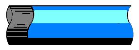
5 Page 5 of 61 INTRODUCTION General Design Consideration For two phase, the respective distributions of the liquid and vapor phases in the flow channel is the important aspect of their description. Their respective distribution takes on some commonly observed flow structures, which are defined as two phase flow patterns that have particular identifying characteristics. Heat transfer coefficients and pressure drops are closely related to the local two phase flow structure of the fluid, and thus two phase pattern prediction is an important aspect of modeling evaporation and condensation. In two-phase flow, interactions between liquid and vapor phases, as influenced by their physical properties and flow rates and by the size, roughness and orientation of the pipe, cause the fluids to flow in various types of patterns. These patterns are called flow regimes. Only one type of flow exists at a given point in a line at any given time. However, as flow conditions change, the flow regime may change from one type to another. In flow of mixtures of the two phases in pipelines, the liquid tends to wet the wall and the gas to concentrate in the center of the channel, but various degrees of dispersion of each phase in the other may exist, depending on operating conditions, particularly the individual flow rates Seven principal flow regimes have been defined to describe flow found in horizontal or slightly inclined pipes. These flow regimes are described below, in order of increasing vapor velocity. In the accompanying sketches, the direction of flow is from left to right.
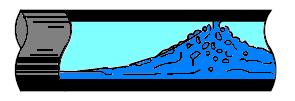
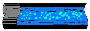
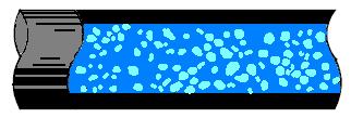
6 Page 6 of Bubble Flow Liquid occupies the bulk of the cross-section and vapor flows in the form of bubbles along the top of the pipe. Vapor and liquid velocities are approximately equal. If the bubbles become dispersed throughout the liquid, this is sometimes called froth flow. In uphill flow bubbles retain their identity over a wider range of conditions. In downhill flow the behavior is displaced in the direction of plug flow. Bubble flow is of importance to the chemical process industry, where the rise of bubbles through a liquid, both individually and in swarms (clusters), has received considerable attention. Properly speaking, bubbly flow is not a fully developed flow regime because given enough time or distance, the bubbles may collide with each other; and their agglomeration could lead to the formation of large bubbles or slug flow. In some instances, where proper care is taken in their generation, the bubbles present in the stream are small enough that they will touch rarely, and bubble flow will persist for a significant distance. 2. Plug Flow As the vapor rate increases, the bubbles coalesce, and alternating plugs of vapor and liquid flow along the top of the pipe with liquid remaining the continuous phase along the bottom. In an uphill orientation, the behavior is displaced in the direction of bubble flow; downhill, stratified flow is favored. 3. Stratified Flow As the vapor rate continues to increase, the plugs become a continuous phase. Vapor flows along the top of the pipe and liquid flows along the bottom. The interface between phases is relatively smooth and the fraction occupied by each phase remains constant. In uphill flow, stratified flow rarely occurs with wavy flow being favored. Downhill, stratified flow is somewhat enhanced, as long as the inclination is not too steep. 4. Wavy Flow As the vapor rate increases still further, the vapor moves appreciably faster than the liquid and the resulting friction at the interface forms liquid waves. The wave amplitude increases with increasing vapor rate. Wavy flow can occur uphill, but over a narrower range of conditions than in a horizontal pipe. Downhill, the waves are
7 Page 7 of 61 milder for a given vapor rate and the transition to slug flow, if it occurs at all, takes place at higher vapor rates than in horizontal pipes. 5. Slug Flow When the vapor rate reaches a certain critical value, the crests of the liquid waves touch the top of the pipe and form frothy slugs. The velocity of these slugs, and that of the alternating vapor slugs, is greater than the average liquid velocity. In the body of a vapor slug the liquid level is depressed so that vapor occupies a large part of the flow area at that point. Uphill, slug flow is initiated at lower vapor rates than in horizontal pipe. Downhill, it takes higher vapor rates to establish slug flow than in horizontal pipe, and the behavior is displaced in the direction of annular flow. Slug flow should be avoided where possible because it may lead to pulsation and vibration in bends, valves and other flow restrictions. 6. Annular Flow The liquid flows as an annular film of varying thickness along the wall, while the vapor flows as a high-speed core down the middle. There is a great deal of slip between phases. Part of the liquid is sheared off from the film by the vapor and is carried along in the core as entrained droplets. At the same time, turbulent eddies in the vapor deposit droplets on the liquid film. The annular film on the wall is thicker at the bottom of the pipe than at the top, the difference decreasing with distance from slug flow conditions. Downstream of bends, most of the liquid will be at the outer wall. In annular flow, the effects of friction pressure drop and momentum outweigh the effect of gravity, so that pipe orientation and direction of flow have less influence than in the previous flow regimes. Annular flow is a very stable flow regime. For this reason and because vapor-liquid mass transfer is favored, this flow regime is advantageous for some chemical reactions. 7. Spray Flow (Mist Flow or Dispersed Flow) When the vapor velocity in annular flow becomes high enough, all of the liquid film is torn away from the wall and is carried by the vapor as entrained droplets. This flow regime is almost completely independent of pipe orientation or direction of flow.
")
 (e)")
8 Page 8 of 61 (a) (b) (c) (d) (e) (f) (g)
9 Page 9 of 61 Figure 1: Flow regime in horizontal pipeline; (a). Bubble flow, (b) Plug flow, (c) Stratified flow, (d) Wafy flow, (e) Slug flow, (f) Annular flow, and (g) Spray flow Flow behavior in vertical pipes, where gravity plays an important role, has been less extensively investigated than has flow in horizontal pipes. Most of the available information on vertical flow pertains to up-flow. Conditions under which certain flow regimes exist depend largely on the orientation of the pipe and the direction of flow. In a situation where stratified or wavy flow would exist in a horizontal pipe, tilting the pipe downward increases the relative velocity of the liquid, making a larger part of the flow area available for the vapor. On the other hand, tilting the pipe upward causes the liquid to drain back downhill until enough has accumulated to block off the entire cross-section. The vapor can then no longer get past the liquid, and therefore pushes a slug of liquid through the inclined section of the line. Five principal flow regimes have been defined to describe vertical flow. These flow regimes are described below, in order of increasing vapor velocity. 1. Slug Flow As the vapor rate increases, bubbles coalesce into slugs which occupy the bulk of the cross-sectional area. Alternating slugs of vapor and liquid move up the pipe with some bubbles of vapor entrained in the liquid slugs. Surrounding each vapor slug is a laminar film of liquid which flows toward the bottom of the slug. As the vapor rate is increased, the lengths and velocity of the vapor slugs increase. Slug flow can occur in the downward direction, but is usually not initiated in that orientation. However, if slug flow is well established in an upward leg of a coil, it will persist in a following downward leg, provided that other conditions remain the same. 2. Froth Flow As the vapor rate increases further, the laminar liquid film is destroyed by vapor turbulence and the vapor slugs become more irregular. Mixing of vapor bubbles with the liquid increases and a turbulent, disordered pattern is formed with ever shortening liquid slugs separating successive vapor slugs. The transition to annular flow is the point at which liquid separation between vapor slugs disappears and the vapor slugs coalesce into a continuous, central core of vapor. Since froth flow has much in common with slug flow, the two regimes are often lumped together and called slug flow. In the downward direction, froth flow behaves much the same as
10 Page 10 of 61 slug flow does, except that the former is more easily initiated in this orientation, particularly if conditions are bordering on those for annular flow. 3. Annular Flow This flow regime is similar to annular flow in horizontal pipe, except that the slip between phases is affected by gravity. In up-flow, the annular liquid film is slowed down by gravity, which increases the difference in velocities between vapor and liquid. In down-flow, the reverse is true, with gravity speeding up the liquid and reducing the difference in velocities between vapor and liquid. On the other hand, the liquid film thickness is more uniform around the circumference of the pipe than in horizontal flow. Annular flow tends to be the dominant regime In vertical down-flow. 4. Mist Flow This flow regime is essentially the same as spray flow in horizontal pipe. The very high vapor rates required to completely disperse the liquid essentially eliminate the effects of orientation and direction of flow. In identification of vertical two-phase flow regimes, annular and mist flow are often considered together (and called annularmist).
11 Page 11 of 61 (a) (b) (c)
 Slug flow, (c) Froth flow, (d) Annular flow, (e) Mist flow, The behavior of a two-phase mixture in a tee is highly unpredictable.")

12 Page 12 of 61 (d) (e) Figure 2: Flow regime in vertical pipeline; (a). Bubble flow, (b) Slug flow, (c) Froth flow, (d) Annular flow, (e) Mist flow, The behavior of a two-phase mixture in a tee is highly unpredictable. Liquid or vapor may prefer one branch over the other resulting in uneven splitting, so that the volume fraction of vapor (or liquid) differs in the two split streams. It is generally true that if the flow entering the tee is a dispersed flow the split will be more even than when the entering stream is in a separated flow regime. The splitting of a two-phase stream in a pipe tee is also dependent on the configuration of the flow. In general the splitting is more even if it is done in a more symmetrical fashion.
13 Page 13 of 61 Splitting is more even in an impacting tee (a) than in a straight-through tee (b) as shown below. In order to maintain symmetry, elbows immediately upstream of an impacting tee should be mounted perpendicular to the plane of the tee. If this is not possible a blanked-off tee should be used instead of the elbow. (a) (b) Figure 3: (a) an impacting tee and (b) a straight-through tee Characteristic of two phase fluid flow 1. Surface tension makes all dynamical problems nonlinear. 2. In the case of air and water at standard temperature and pressure, the density of the two phases differs by a factor of about Similar differences are typical of water liquid/water vapor densities. 3. The sound speed changes dramatically for materials undergoing phase change, and can be orders of magnitude different. This introduces compressible effects into the problem. 4. The phase changes are not instantaneous, and the liquid vapor system will not necessarily be in phase equilibrium.
14 Page 14 of 61 DEFINITIONS Coalesce - to grow together or into one body: The two lakes coalesced into one. Critical point - The location along the flow path that experiences the steepest pressure gradient in critical flow. For a valve or a nozzle, the critical point is located at the narrowest point of the device and for a crack or a short pipe, it is usually at the exit. Critical pressure ratio - the ratio of the pressure at the critical point to the stagnation pressure. Critical flow - If the pressure drop is severe enough, a situation can arise in which the release rate becomes independent of the surrounding pressure. In other words, the release rate cannot be increased by further reduction in the surrounding pressure Fitting - An accessory such as a locknut, bushing, or other part of a wiring system that is intended primarily to perform a mechanical rather than an electrical function. Flashing - When a liquid or a vapor-liquid mixture under pressure is released to the surroundings through a pressure relief valve or a crack in a pipe or vessel Flow maldistribution - In branching flows, such as tee junctions or perforated pipe distributors, the flow maldistribution measures the preferential distribution of flow among alternative paths. Flow regime - A range of stream flows having similar bed forms, flow resistance, and means of transporting sediment. When two phases flow co-currently in a channel, they can arrange themselves in a number of different configurations. Stagnation - Location upstream of the critical point where flow is stagnant or moving very slowly. Velocity slip - In actual two-phase flow there is slip between vapor and liquid, with vapor flowing at a higher average velocity. Fanning Friction Factor - Empirical factor in the Fanning equation for pressure drop in straight pipe. This factor is a function of Reynolds Number and relative pipe wall
15 Page 15 of 61 roughness, ε/d. For a given class of pipe material, the roughness is relatively independent of the pipe diameter, so that in a plot of f vs. Re, d often replaces ε/d as a parameter. The Fanning friction factor should not be confused with the Darcy friction factor, which is four times as large. Laminar or Viscous Flow - Laminar flow occurs when adjacent layers of fluid move relative to each other in smooth streamlines, without macroscopic mixing. In laminar flow, viscous shear, which is caused by molecular momentum exchange between fluid layers, is the predominant influence in establishing the fluid flow. This flow type occurs in pipes when Re < 2,100. Liquid slugging - a condition which occurs when liquid is allowed to enter one or more cylinders. Where extreme cases of flooded start or liquid flood back occur. Maldistribution - bad or faulty distribution, undesirable inequality or unevenness of placement or apportionment (as of population, resources, or wealth) over an area or among members of a group Phase equilibrium phase where The energy of a system does not change when a particle undergoes a transition from one phase to another at equilibrium. In other words, the chemical potentials of each component in the different phases are equal at equilibrium Physical properties any property use to characterize matter and energy and their interactions. The measurement of physical properties may change the arrangement of matter but not the structure of its molecules. Pipeline - a line of pipe or A conduit of pipe with pumps, valves, and control devices for conveying liquids, gases, or finely divided solids. Pressure drop - decrease in pressure from one point in a pipe or tube to another point downstream. Pressure drop occurs with frictional forces on a fluid as it flows through the tube. Reynolds Number, Re - A dimensionless number which expresses the ratio of inertial to viscous forces in fluid flow.
16 Page 16 of 61 Specific gravity - The ratio of the mass of a given volume of a substance to that of another equal volume of another substance used as standard. Unless otherwise stated, air is used as the standard for gases and water for liquids, with the volumes measured at 60 F and standard atmospheric pressure. Slug catchers - devices at the downstream end or other intermediate points of a pipeline to absorb the fluctuating liquid inlet flow rates through liquid level fluctuation. Surface tension - A property of liquids arising from unbalanced molecular cohesive forces at or near the surface, as a result of which the surface tends to contract and has properties resembling those of a stretched elastic membrane. Transition Flow - Flow regime lying between laminar and turbulent flow. In this regime velocity fluctuations may or may not be present and flow may be intermittently laminar and turbulent. This flow type occurs in pipes when 2,100 < Re < 4,000. Turbulent Flow - Turbulent flow occurs when macroscopic mixing results both perpendicular to, and in the direction of, the main flow. Turbulent flow is characterized by fluid particles having fluctuating motions and erratic paths. It is the flow that occurs when inertial forces are the predominant influence in establishing the fluid flow. This flow type occurs in pipes in industrial situations when Re > 4,000. Under very controlled laboratory situations, laminar flow may persist at Re > 4,000. Water Hammer - Water hammer is the dynamic pressure surge that results from the sudden transformation of the kinetic energy in a flowing fluid into pressure when the flow is suddenly stopped. The sudden closing of a valve can cause a water hammer. Water hammer pressure can be large enough to shatter pump casings or burst line pipe and should, therefore, be considered in the design of pipes.
17 Page 17 of 61 NOMENCLATURE A Radius-sectional area, ft 2 A P Cross sectional area of pipe, ft 2 Av Cross sectional area based on valve nominal size, ft 2 C Pipe constraint coefficient C LO Heat capacity of liquid at stagnation conditions, Btu/lbmF d Inside diameter of pipe, in E Pipe material Young s modulus, lbf/ft 2 Ek The kinetic energy per unit volume of the inlet stream, psi fn The single phase friction factor, f tpr The two-phase friction factor ratio, g Gravity constant, ft/s 2 G C Critical mass flux, lbm/ft 2 -s G C * Normalized critical mass flux Gt Total mass velocity, lbm/ft 2 s H Surge pressure, ft-liq ΣH The vertical elevation rise of a hill, ft h GO Enthalpy of vapor at stagnation conditions, Btu/lbm H Lf Elevation head factor h LO Enthalpy of liquid at stagnation conditions, Btu/lbm IL The liquid inventory in the pipe, ft 3 J Factor for calculating head loss along a perforated pipe distributor. K Liquid bulk modulus, lbf/ft 2 L Length of pipe, ft L m Length of line, miles P e The elevation pressure drop P f The frictional pressure drop Po The required pressure drop, psi P p The pressure change along the pipe due to friction and momentum recovery P C Critical pressure, psi P O Stagnation pressure, psi Q Quantity (volume) flow rate at conditions, gpm Q G Gas volumetric flow rate at flowing conditions, ft 3 /s Q L Liquid volumetric flow rate at flowing conditions, ft 3 /s Re mix Reynolds Number of inlet mixture
18 Page 18 of 61 R L t Te T O Tv V V 2ΦO V GO V LO v mix v sg v sl v w W x X x O Y The liquid holdup fraction Ppipe wall thickness, in Effective valve stroking time, s Stagnation temperature, R Valve stroking time, s Change of linear flow velocity, ft/s Two-phase specific volume Specific volume of vapor at stagnation conditions, ft 3 /lbm Specific volume of liquid at stagnation conditions, ft 3 /lbm Velocity of inlet mixture The superficial vapor velocity, ft/s Superficial velocity of liquid, ft/s Wave speed, ft/s Total mass flow rate, lbm/h Mass fraction vapor (quality), Parameter to determine flow regime in horizontal pipe Stagnation quality Parameter to determine flow regime in horizontal pipe Greek letters α Velocity correction factor. γ Parameter in R L for vertical pipe η Critical pressure ratio λ Volume fraction liquid µ G Gas viscosity, cp µ L Liquid viscosity, cp µ mix Viscosity of inlet mixture ρ G Vapor density, lbm/ft 3 ρ L Liquid density, lb/ft 3 ρ mix Density of inlet mixture σ Liquid surface tension, dynes/cm Φ Parameter ψ Parameter
Irrigation &Hydraulics Department lb / ft to kg/lit.
 CAIRO UNIVERSITY FLUID MECHANICS Faculty of Engineering nd Year CIVIL ENG. Irrigation &Hydraulics Department 010-011 1. FLUID PROPERTIES 1. Identify the dimensions and units for the following engineering
Numerical Analysis of Two Phase Flow Patterns in Vertical and Horizontal Pipes
 Numerical Analysis of Two Phase Flow Patterns in Vertical and Horizontal Pipes MOHAMMED A. ABDULWAHID, HASANAIN J. KAREEM, MUJTABA A. ALMUDHAFFAR Thermal Mechanical Engineering, Southern Technical University,
Bioreactor System ERT 314. Sidang /2011
 Bioreactor System ERT 314 Sidang 1 2010/2011 Chapter 2:Types of Bioreactors Week 4 Flow Patterns in Agitated Tanks The flow pattern in an agitated tank depends on the impeller design, the properties of
Section 2 Multiphase Flow, Flowing Well Performance
 Section 2 Multiphase Flow, Flowing Well Performance Multiphase Vertical Flow When producing an oil or gas well, the flow of the fluids up the tubing will be in most cases be 2 phase, liquid and gas. The
Chapter 15 Fluid. Density
 Density Chapter 15 Fluid Pressure Static Equilibrium in Fluids: Pressure and Depth Archimedes Principle and Buoyancy Applications of Archimedes Principle By Dr. Weining man 1 Units of Chapter 15 Fluid
Lecture Outline Chapter 15. Physics, 4 th Edition James S. Walker. Copyright 2010 Pearson Education, Inc.
 Lecture Outline Chapter 15 Physics, 4 th Edition James S. Walker Chapter 15 Fluids Density Units of Chapter 15 Pressure Static Equilibrium in Fluids: Pressure and Depth Archimedes Principle and Buoyancy
Yutaek Seo. Subsea Engineering
 Yutaek Seo Subsea Engineering Inlet receiving Gas and liquids that enter the gas processing facilities pass emergency shutdown valves, and then go to inlet receiving, where condensed phases drop out. Gas
Static Fluids. **All simulations and videos required for this package can be found on my website, here:
 DP Physics HL Static Fluids **All simulations and videos required for this package can be found on my website, here: http://ismackinsey.weebly.com/fluids-hl.html Fluids are substances that can flow, so
Homework #14, due Wednesday, Nov. 28 before class. Quiz #14, Wednesday November 28 at the beginning of class
 ANNOUNCEMENTS Homework #14, due Wednesday, Nov. 28 before class Conceptual questions: Chapter 14, #8 and #16 Problems: Chapter 14, #58, #66 Study Chapter 14 by Wednesday Quiz #14, Wednesday November 28
THE INNER WORKINGS OF A SIPHON Jacques Chaurette p. eng. January 2003
 THE INNER WORKINGS OF A SIPHON Jacques Chaurette p. eng. www.lightmypump.com January 2003 Synopsis The objective of this article is to explain how a siphon works. The difference between low pressure, atmospheric
MEMORIAL UNIVERSITY OF NEWFOUNDLAND Faculty of Engineering and Applied Science FLUID MECHANICS LABORATORY PIPE FRICTION
 MEMORIAL UNIVERSITY OF NEWFOUNDLAND Faculty of Engineering and Applied Science FLUID MECHANICS LABORATORY PIPE FRICTION Objective To estimate the fluid pressure drops and roughness specifications for copper
The effect of back spin on a table tennis ball moving in a viscous fluid.
 How can planes fly? The phenomenon of lift can be produced in an ideal (non-viscous) fluid by the addition of a free vortex (circulation) around a cylinder in a rectilinear flow stream. This is known as
Multiphase Flow Prof. Gargi Das Department of Chemical Engineering Indian Institute of Technology, Kharagpur
 Multiphase Flow Prof. Gargi Das Department of Chemical Engineering Indian Institute of Technology, Kharagpur Module No. # 01 Lecture No. # 02 Estimation of Flow Patterns Well very good morning to all of
Applied Fluid Mechanics
 Applied Fluid Mechanics 1. The Nature of Fluid and the Study of Fluid Mechanics 2. Viscosity of Fluid 3. Pressure Measurement 4. Forces Due to Static Fluid 5. Buoyancy and Stability 6. Flow of Fluid and
Process Dynamics, Operations, and Control Lecture Notes - 20
 Lesson 0. Control valves 0.0 Context Controller output is a signal that varies between 0 and 100%. Putting this signal to use requires a final control element, a device that responds to the controller
COMPUTATIONAL FLOW MODEL OF WESTFALL'S LEADING TAB FLOW CONDITIONER AGM-09-R-08 Rev. B. By Kimbal A. Hall, PE
 COMPUTATIONAL FLOW MODEL OF WESTFALL'S LEADING TAB FLOW CONDITIONER AGM-09-R-08 Rev. B By Kimbal A. Hall, PE Submitted to: WESTFALL MANUFACTURING COMPANY September 2009 ALDEN RESEARCH LABORATORY, INC.
PETROLEUM & GAS PROCESSING TECHNOLOGY (PTT 365) SEPARATION OF PRODUCED FLUID
 SEPARATION OF PRODUCED FLUID") PETROLEUM & GAS PROCESSING TECHNOLOGY (PTT 365) SEPARATION OF PRODUCED FLUID Miss Nur Izzati Bte Iberahim Introduction Well effluents flowing from producing wells come out in two phases: vapor and liquid
PETROLEUM & GAS PROCESSING TECHNOLOGY (PTT 365) SEPARATION OF PRODUCED FLUID Miss Nur Izzati Bte Iberahim Introduction Well effluents flowing from producing wells come out in two phases: vapor and liquid
TABLE OF CONTENT
 Page : 1 of 22 Project Engineering Standard www.klmtechgroup.com KLM Technology #03-12 Block Aronia, Jalan Sri Perkasa 2 Taman Tampoi Utama 81200 Johor Bahru Malaysia S) TABLE OF CONTENT SCOPE 2 VESSELS
L 15 Fluids [4] The Venturi Meter. Bernoulli s principle WIND. Basic principles of fluid motion. Why does a roof blow off in high winds?
![L 15 Fluids [4] The Venturi Meter. Bernoulli s principle WIND. Basic principles of fluid motion. Why does a roof blow off in high winds?](/thumbs/72/68053820.jpg "L 15 Fluids [4] The Venturi Meter. Bernoulli s principle WIND. Basic principles of fluid motion. Why does a roof blow off in high winds?") Basic principles of fluid motion L 15 Fluids [4] >Fluid flow and Bernoulli s s principle >Airplanes and curveballs >viscosity (real fluids) v 1 Continuity equation: v A = constant A 1 A 2 v 2 Bernoulli
Basic principles of fluid motion L 15 Fluids [4] >Fluid flow and Bernoulli s s principle >Airplanes and curveballs >viscosity (real fluids) v 1 Continuity equation: v A = constant A 1 A 2 v 2 Bernoulli
Pump Selection and Sizing (ENGINEERING DESIGN GUIDELINE)
") Guidelines for Processing Plant Page : 1 of 64 Feb 2007 (ENGINEERING DESIGN GUIDELINE) Author: A L Ling Checked by: Karl Kolmetz TABLE OF CONTENT INTRODUCTION Scope 5 General Design Consideration Type
Guidelines for Processing Plant Page : 1 of 64 Feb 2007 (ENGINEERING DESIGN GUIDELINE) Author: A L Ling Checked by: Karl Kolmetz TABLE OF CONTENT INTRODUCTION Scope 5 General Design Consideration Type
Meteorology & Air Pollution. Dr. Wesam Al Madhoun
 Meteorology & Air Pollution Dr. Wesam Al Madhoun Dispersion = Advection (Transport) + Dilution (Diffusion) Source Transport Receptor Re-entrainment Fick s law of diffusion J= - D * D C/Dx Where, J= Mass
Flow and Mixing in the Liquid between Bubbles
 Excerpt from the Proceedings of the COMSOL Conference 2009 Boston Flow and Mixing in the Liquid between Bubbles Bruce A. Finlayson, Professor Emeritus of Chemical Engineering Department of Chemical Engineering,
PHYS 101 Previous Exam Problems
 PHYS 101 Previous Exam Problems CHAPTER 14 Fluids Fluids at rest pressure vs. depth Pascal s principle Archimedes s principle Buoynat forces Fluids in motion: Continuity & Bernoulli equations 1. How deep
CEE 452/652. Week 9, Lecture 2 Absorption. Dr. Dave DuBois Division of Atmospheric Sciences, Desert Research Institute
 CEE 452/652 Week 9, Lecture 2 Absorption Dr. Dave DuBois Division of Atmospheric Sciences, Desert Research Institute Today s topics Today s topic: chapter 13 on absorption Cover odor control on Tuesday,
Air Pollution Dispersion
 Air Pollution Dispersion Dispersion Processes Convective Dispersion Air Parcel Dynamics Adiabatic Process Lapse Rate Equilibrium and Stability Atmospheric Stability Stability and Dispersion Temperature
UNIT 15 WATER HAMMER AND SURGE TANKS
 UNT 15 WATER HAMMER AND SURGE TANKS Structure 15.1 ntroduction Objectives 15.2 Water Hammer 15.2.1 Expression for Rise in Pressure 15.3 Rapid Acceleration of Flow 15.4 Surge Tanks 15.5 Summary 15.6 Keywords
Liquid -Vapor. Contacting columns
 Liquid -Vapor * Contacting columns Distillation Column Design The design of a distillation column can be divided into the following steps: 1. Specify the degree of separation required: set product specifications.
CVEN 311 Fluid Dynamics Fall Semester 2011 Dr. Kelly Brumbelow, Texas A&M University. Final Exam
 CVEN 311 Fluid Dynamics Fall Semester 2011 Dr. Kelly Brumbelow, Texas A&M University Final Exam 8 pages, front & back, not including reference sheets; 21 questions An excerpt from the NCEES Fundamentals
EDUCTOR. principle of operation
 EDUCTOR principle of operation condensate and mixing eductor s are designed to mix two liquids intimately in various proportions in operations where the pressure liquid is the greater proportion of the
FLUID MECHANICS Time: 1 hour (ECE-301) Max. Marks :30
 Max. Marks :30") B.Tech. [SEM III(ME&CE)] QUIZ TEST-1 (Session : 2013-14) Time: 1 hour (ECE-301) Max. Marks :30 Note: Attempt all questions. PART A Q1. The velocity of the fluid filling a hollow cylinder of radius 0.1
B.Tech. [SEM III(ME&CE)] QUIZ TEST-1 (Session : 2013-14) Time: 1 hour (ECE-301) Max. Marks :30 Note: Attempt all questions. PART A Q1. The velocity of the fluid filling a hollow cylinder of radius 0.1
Tutorial. BOSfluids. Relief valve
 Tutorial Relief valve The Relief valve tutorial describes the theory and modeling process of a pressure relief valve or safety valve. It covers the algorithm BOSfluids uses to model the valve and a worked
Vortex Separation Technologies. Engineered Solutions to Separation Problems
 Vortex Separation Technologies Engineered Solutions to Separation Problems Vortex Technology Internals use the high-energy momentum of fluids to produce a high G force which sends the liquids and solids
Computational Analysis of Oil Spill in Shallow Water due to Wave and Tidal Motion Madhu Agrawal Durai Dakshinamoorthy
 Computational Analysis of Oil Spill in Shallow Water due to Wave and Tidal Motion Madhu Agrawal Durai Dakshinamoorthy 1 OUTLINE Overview of Oil Spill & its Impact Technical Challenges for Modeling Review
Micro Motion Pressure Drop Testing
 12/2018 Micro Motion Pressure Drop Testing www.emerson.com/micromotion Introduction Micro Motion has traditionally taken a very conservative approach to pressure drop, with single pressure measurements
OLGA. The Dynamic Three Phase Flow Simulator. Input. Output. Mass transfer Momentum transfer Energy transfer. 9 Conservation equations
 서유택 Flow Assurance The Dynamic Three Phase Flow Simulator 9 Conservation equations Mass (5) Momentum (3) Energy (1) Mass transfer Momentum transfer Energy transfer Input Boundary and initial conditions
Solutions, Standards and Software. SEPARATOR VESSELS SIZING AND SELECTION (ENGINEERING DESIGN GUIDELINE)
") Page : 1 of 71 for Processing Plant Solutions KLM Technology #03-12 Block Aronia, Jalan Sri Perkasa 2 Taman Tampoi Utama 81200 Johor Bahru Malaysia Solutions, Standards and Software www.klmtechgroup.com
Page : 1 of 71 for Processing Plant Solutions KLM Technology #03-12 Block Aronia, Jalan Sri Perkasa 2 Taman Tampoi Utama 81200 Johor Bahru Malaysia Solutions, Standards and Software www.klmtechgroup.com
Numerical Simulations of a Train of Air Bubbles Rising Through Stagnant Water
 Numerical Simulations of a Train of Air Bubbles Rising Through Stagnant Water Hong Xu, Chokri Guetari ANSYS INC. Abstract Transient numerical simulations of the rise of a train of gas bubbles in a liquid
44 (0) E:
 E:") FluidFlow Relief Valve Sizing Handbook Flite Software 2016 Flite Software N.I. Ltd, Block E, Balliniska Business Park, Springtown Rd, Derry, BT48 0LY, N. Ireland. T: 44 (0) 2871 279227 E: sales@fluidflowinfo.com
FluidFlow Relief Valve Sizing Handbook Flite Software 2016 Flite Software N.I. Ltd, Block E, Balliniska Business Park, Springtown Rd, Derry, BT48 0LY, N. Ireland. T: 44 (0) 2871 279227 E: sales@fluidflowinfo.com
ANSWERS TO QUESTIONS IN THE NOTES AUTUMN 2018
 ANSWERS TO QUESTIONS IN THE NOTES AUTUMN 2018 Section 1.2 Example. The discharge in a channel with bottom width 3 m is 12 m 3 s 1. If Manning s n is 0.013 m -1/3 s and the streamwise slope is 1 in 200,
Applications of Bernoulli s principle. Principle states that areas with faster moving fluids will experience less pressure
 Applications of Bernoulli s principle Principle states that areas with faster moving fluids will experience less pressure Artery o When blood flows through narrower regions of arteries, the speed increases
Transient Analyses In Relief Systems
 Transient Analyses In Relief Systems Dirk Deboer, Brady Haneman and Quoc-Khanh Tran Kaiser Engineers Pty Ltd ABSTRACT Analyses of pressure relief systems are concerned with transient process disturbances
Structure of Mechanically Agitated Gas-Liquid Contactors
 Structure of Mechanically Agitated Gas-Liquid Contactors 5 2 Structure of Mechanically Agitated Gas-Liquid Contactors 2.1 The vessel geometry The most commonly adopted geometry of a stirred gas-liquid
A REVIEW OF T-JUNCTION GEOMETRICAL EFFECT ON TWO-PHASE SEPARATION
 A REVIEW OF T-JUNCTION GEOMETRICAL EFFECT ON TWO-PHASE SEPARATION Ahmed Saieed, Ban Sam, William Pao 1, Fakhruldin M. Hashim and Rohaizad B. M. Norpiah Mechanical Engineering Department, Universiti Teknologi
Chapter 15 Fluids. Copyright 2010 Pearson Education, Inc.
 Chapter 15 Fluids Density Units of Chapter 15 Pressure Static Equilibrium in Fluids: Pressure and Depth Archimedes Principle and Buoyancy Applications of Archimedes Principle Fluid Flow and Continuity
Process Equipment Design Guidelines Chapter Four Instrumentation Selection and Sizing (Engineering Design Guidelines)
") Guidelines for Processing www.klmtechgroup.com Page : 1 of 56 Rev 1 - April 2007 Rev 2 Nov 2010 Rev 3 KLM Technology #03-12 Block Aronia, Jalan Sri Perkasa 2 Taman Tampoi Utama 81200 Johor Bahru Process
Guidelines for Processing www.klmtechgroup.com Page : 1 of 56 Rev 1 - April 2007 Rev 2 Nov 2010 Rev 3 KLM Technology #03-12 Block Aronia, Jalan Sri Perkasa 2 Taman Tampoi Utama 81200 Johor Bahru Process
Chapter 8: Reservoir Mechanics
 PTRT 1472: Petroleum Data Management II Chapter 8: Reservoir Mechanics - Reservoir drives Types of Natural Gas Reservoir Fluids Natural gas is petroleum in a gaseous state, so it is always accompanied
Chapter 13. liquids. gases. 1) Fluids exert pressure. a) because they're made up of matter and therefore forces are applied to them
 Fluids exert pressure. a) because they're made up of matter and therefore forces are applied to them") \ Chapter 13 Fluids 1) Fluids exert pressure a) because they're made up of matter and therefore forces are applied to them liquids gases b) they are made of matter in constant motion colliding with other
\ Chapter 13 Fluids 1) Fluids exert pressure a) because they're made up of matter and therefore forces are applied to them liquids gases b) they are made of matter in constant motion colliding with other
UNUSUAL ASPECTS OF PUMP SYSTEMS. Jacques Chaurette p. eng. ww.lightmypump.com July 2003
 UNUSUAL ASPECTS OF PUMP SYSTEMS Jacques Chaurette p. eng. ww.lightmypump.com July 2003 There are many unusual aspects to pump systems. It is some of these aspects that make pump systems fascinating for
THE BRIDGE COLLAPSED IN NOVEMBER 1940 AFTER 4 MONTHS OF ITS OPENING TO TRAFFIC!
 OUTLINE TACOMA NARROWS BRIDGE FLOW REGIME PAST A CYLINDER VORTEX SHEDDING MODES OF VORTEX SHEDDING PARALLEL & OBLIQUE FLOW PAST A SPHERE AND A CUBE SUMMARY TACOMA NARROWS BRIDGE, USA THE BRIDGE COLLAPSED
Factors that determine water movement. Morphometry Structure of stratification Wind patterns
 Water Movement Factors that determine water movement Morphometry Structure of stratification Wind patterns Turbulent and laminar flow Laminar flow - smooth, unidirectional flow Low velocity Rare in nature
Generating Calibration Gas Standards
 Technical Note 1001 Metronics Inc. Generating Calibration Gas Standards with Dynacal Permeation Devices Permeation devices provide an excellent method of producing known gas concentrations in the PPM and
Effect of 180 bends on gas/liquid flows in vertical upward and downward pipes
 Computational Methods in Multiphase Flow VII 435 Effect of 180 bends on gas/liquid flows in vertical upward and downward pipes A. Almabrok, L. Lao & H. Yeung Department of Offshore, Process and Energy
PURE SUBSTANCE. Nitrogen and gaseous air are pure substances.
 CLASS Third Units PURE SUBSTANCE Pure substance: A substance that has a fixed chemical composition throughout. Air is a mixture of several gases, but it is considered to be a pure substance. Nitrogen and
Chapter # 08 Waves. [WAVES] Chapter # 08
![Chapter # 08 Waves. [WAVES] Chapter # 08](/thumbs/94/121079132.jpg "Chapter # 08 Waves. [WAVES] Chapter # 08") Chapter # 08 Waves Q2) Write short answers of the following questions. i) What is the difference between progressive and stationary waves? Answer: Progressive Waves 1 Progressive waves are the result of
Chapter # 08 Waves Q2) Write short answers of the following questions. i) What is the difference between progressive and stationary waves? Answer: Progressive Waves 1 Progressive waves are the result of
LOW PRESSURE EFFUSION OF GASES revised by Igor Bolotin 03/05/12
 LOW PRESSURE EFFUSION OF GASES revised by Igor Bolotin 03/05/ This experiment will introduce you to the kinetic properties of low-pressure gases. You will make observations on the rates with which selected
SPECIFYING MOTIONLESS MIXERS
 SPECIFYING MOTIONLESS MIXERS The operating cost for the energy necessary to mix fluids with a motionless mixer is usually far lower than for any competitive mixing technique. An extruder which melts, mixes
Influence of rounding corners on unsteady flow and heat transfer around a square cylinder
 Influence of rounding corners on unsteady flow and heat transfer around a square cylinder S. K. Singh Deptt. of Mech. Engg., M. B. M. Engg. College / J. N. V. University, Jodhpur, Rajasthan, India Abstract
MODELING AND SIMULATION OF VALVE COEFFICIENTS AND CAVITATION CHARACTERISTICS IN A BALL VALVE
 Proceedings of the 37 th International & 4 th National Conference on Fluid Mechanics and Fluid Power FMFP2010 December 16-18, 2010, IIT Madras, Chennai, India FMFP2010 341 MODELING AND SIMULATION OF VALVE
. In an elevator accelerating upward (A) both the elevator accelerating upward (B) the first is equations are valid
 both the elevator accelerating upward (B) the first is equations are valid") IIT JEE Achiever 2014 Ist Year Physics-2: Worksheet-1 Date: 2014-06-26 Hydrostatics 1. A liquid can easily change its shape but a solid cannot because (A) the density of a liquid is smaller than that of
IIT JEE Achiever 2014 Ist Year Physics-2: Worksheet-1 Date: 2014-06-26 Hydrostatics 1. A liquid can easily change its shape but a solid cannot because (A) the density of a liquid is smaller than that of
Lesson 12: Fluid statics, Continuity equation (Sections ) Chapter 9 Fluids
 Chapter 9 Fluids") Lesson : luid statics, Continuity equation (Sections 9.-9.7) Chapter 9 luids States of Matter - Solid, liquid, gas. luids (liquids and gases) do not hold their shapes. In many cases we can think of liquids
Lesson : luid statics, Continuity equation (Sections 9.-9.7) Chapter 9 luids States of Matter - Solid, liquid, gas. luids (liquids and gases) do not hold their shapes. In many cases we can think of liquids
Development of High-speed Gas Dissolution Device
 Development of High-speed Gas Dissolution Device Yoichi Nakano*, Atsushi Suehiro**, Tetsuhiko Fujisato***, Jun Ma**** Kesayoshi Hadano****, Masayuki Fukagawa***** *Ube National College of Technology, Tokiwadai
Two-phase Flow Across Small Diameter Split U-type Junctions
 Proceedings of Fifth International Conference on Enhanced, Compact and Ultra-Compact Heat Echangers: Science, Engineering and Technology, Eds. R.K. Shah, M. Ishizuka, T.M. Rudy, and V.V. Wadekar, Engineering
Undertow - Zonation of Flow in Broken Wave Bores
 Lecture 22 Nearshore Circulation Undertow - Zonation of Flow in Broken Wave Bores In the wave breaking process, the landward transfer of water, associated with bore and surface roller decay within the
Gas Lift Workshop Doha Qatar 4-88 February Gas Lift Optimisation of Long Horizontal Wells. by Juan Carlos Mantecon
 Gas Lift Workshop Doha Qatar 4-88 February 2007 Gas Lift Optimisation of Long Horizontal Wells by Juan Carlos Mantecon 1 Long Horizontal Wells The flow behavior of long horizontal wells is similar to pipelines
Application Worksheet
 Application Worksheet All dimensions are nominal. Dimensions in [ ] are in millimeters. Service Conditions Medium Through Valve: Required C v : Temperature Maximum: Minimum: Normal: Flow Maximum: Minimum:
API th Edition Ballot Item 7.8 Work Item 4 Gas Breakthrough
 API 521 7 th Edition Ballot Item 7.8 Work Item 4 Gas Breakthrough NOTE: This is a reballot of previously approved API 521 7 th Edition Ballot Item 6.3 which was modified based on comments. Comments should
****** * EX * ****** DWN W.W.POWELL CALCULATION OF FLOW LOSSES IN INLET CHK D.PAPA AND DISCHARGE HEADERS ASSOCIATED WITH
 BC ****** * EX * ****** DWN W.W.POWELL 4-17-75 CALCULATION OF FLOW LOSSES IN INLET CHK D.PAPA 4-17-75 AND DISCHARGE HEADERS ASSOCIATED WITH APPR APPR SAFETY RELIEF VALVES SIZE REV APPR A 02.0175.128 L
Wave Motion. interference destructive interferecne constructive interference in phase. out of phase standing wave antinodes resonant frequencies
 Wave Motion Vocabulary mechanical waves pulse continuous periodic wave amplitude period wavelength period wave velocity phase transverse wave longitudinal wave intensity displacement amplitude phase velocity
NOTES ON WATER HAMMER. 55
 NOTES ON WATER HAMMER. 55 NOTES ON WATER HAMMER. By A. B. Robison. When the flow conditions of a liquid in a pipe line are varied by the opening or closing of a valve or the equivalent, a change in the
Air Eliminators and Combination Air Eliminators Strainers
 Description Air Eliminators and Combination Air Eliminator Strainers are designed to provide separation, elimination and prevention of air in piping systems for a variety of installations and conditions.
Water Hammer In Irrigation Systems 1
 CIR828 1 G. A. Clark and D. Z. Haman 2 Irrigation system design includes pump sizing and selection, valve sizing and selection, and pipe sizing as well as the proper selection and placement of many other
Numerical simulation of an intermediate sized bubble rising in a vertical pipe
 Computational Methods in Multiphase Flow V 111 Numerical simulation of an intermediate sized bubble rising in a vertical pipe J. Hua 1, S. Quan 2 & J. Nossen 1 1 Department of Process and Fluid Flow Technology,
Fluid Flow. Link. Flow» P 1 P 2 Figure 1. Flow Model
 Fluid Flow Equipment: Water reservoir, output tubes of various dimensions (length, diameter), beaker, electronic scale for each table. Computer and Logger Pro software. Lots of ice.temperature probe on
1. All fluids are: A. gases B. liquids C. gases or liquids D. non-metallic E. transparent ans: C
 Chapter 14: FLUIDS 1 All fluids are: A gases B liquids C gases or liquids D non-metallic E transparent 2 Gases may be distinguished from other forms of matter by their: A lack of color B small atomic weights
Experiment (13): Flow channel
: Flow channel") Experiment (13): Flow channel Introduction: An open channel is a duct in which the liquid flows with a free surface exposed to atmospheric pressure. Along the length of the duct, the pressure at the surface
Experiment (13): Flow channel Introduction: An open channel is a duct in which the liquid flows with a free surface exposed to atmospheric pressure. Along the length of the duct, the pressure at the surface
Unsteady Flow in Pipes
 The Islamic University of Gaza Faculty of Engineering Civil Engineering Department Hydraulics - ECIV 3322 Chapter 4 Unsteady Flow in Pipes Water Hammer Phenomenon in pipelines A sudden change of flow rate
Suppress Your Surges: Surge Suppression Fundamentals. April 13, 2017
 Suppress Your Surges: Surge Suppression Fundamentals April 13, 2017 How Bad Can Waterhammer Really Be? 2 Workshop Agenda What is waterhammer? Causes of waterhammer Instantaneous surge pressures Surges
Predicting and Controlling Bubble Clogging in Bioreactor for Bone Tissue Engineering
 Predicting and Controlling Bubble Clogging in Bioreactor for Bone Tissue Engineering Marina Campolo, Dafne Molin, Alfredo Soldati Centro Interdipartimentale di Fluidodinamica e Idraulica and Department
CHAPTER 9 Fluids. Units
 CHAPTER 9 Fluids Units Fluids in Motion; Flow Rate and the Equation of Continuity Bernoulli s Equation Applications of Bernoulli s Principle Viscosity Flow in Tubes: Poiseuille s Equation, Blood Flow Surface
Gas viscosity ( ) Carr-Kobayashi-Burrows Correlation Method Lee-Gonzalez-Eakin Method. Carr-Kobayashi-Burrows Correlation Method
 Carr-Kobayashi-Burrows Correlation Method Lee-Gonzalez-Eakin Method. Carr-Kobayashi-Burrows Correlation Method") Gas viscosity The viscosity of a fluid is a measure of the internal fluid friction (resistance) to flow. If the friction between layers of the fluid is small, i.e., low viscosity, an applied shearing force
Gas viscosity The viscosity of a fluid is a measure of the internal fluid friction (resistance) to flow. If the friction between layers of the fluid is small, i.e., low viscosity, an applied shearing force
(Refer Slide Time: 2:16)
") Fluid Machines. Professor Sankar Kumar Som. Department Of Mechanical Engineering. Indian Institute Of Technology Kharagpur. Lecture-23. Diffuser and Cavitation. Good morning and welcome you all to this
Fluid Machines. Professor Sankar Kumar Som. Department Of Mechanical Engineering. Indian Institute Of Technology Kharagpur. Lecture-23. Diffuser and Cavitation. Good morning and welcome you all to this
Chapter 3 Atmospheric Thermodynamics
 Chapter 3 Atmospheric Thermodynamics Spring 2017 Partial Pressure and Dalton Dalton's law of partial pressure: total pressure exerted by a mixture of gases which do not interact chemically is equal to
OIL AND GAS INDUSTRY
 This case study discusses the sizing of a coalescer filter and demonstrates its fouling life cycle analysis using a Flownex model which implements two new pressure loss components: - A rated pressure loss
Pigging as a Flow Assurance Solution Avoiding Slug Catcher Overflow
 Pigging as a Flow Assurance Solution Avoiding Slug Catcher Overflow Aidan O'Donoghue, Pipeline Research Limited, Glasgow, UK This paper sets out to provide an initial method of assessing the bypass requirements
Gerald D. Anderson. Education Technical Specialist
 Gerald D. Anderson Education Technical Specialist The factors which influence selection of equipment for a liquid level control loop interact significantly. Analyses of these factors and their interactions
HANDBOOK SAFETY DEVICES. Ed SAFETY DEVICES DS-ED 01/ ENG 1
 HANDBOOK Ed. 2017 1 CHAPTER 5 SELECTION CRITERIA FOR SAFETY VALVES CALCULATION OF THE DISCHARGE CAPACITY (Ref. EN 13136:2013) The evaluation of the minimum required discharge capacity of safety valves
Multiple port vessels.
 INTRODUCTION Multiple port vessels. Hydraulic design of side-ported RO vessel arrangements (How to get the best out of the side-ported vessels) This document has the final target to show the best multiport
Experiment 8: Minor Losses
 Experiment 8: Minor Losses Purpose: To determine the loss factors for flow through a range of pipe fittings including bends, a contraction, an enlargement and a gate-valve. Introduction: Energy losses
Today: waves. Exam Results. Wave Motion. What is moving? Motion of a piece of the rope. Energy transport
 Exam: Exam scores posted on Learn@UW No homework due next week Exam Results D C BC B AB A Today: waves Have studied Newton s laws, motion of particles, momentum, energy, etc. Laws for describing things
Chapter 16 Test. Directions: Write the correct letter on the blank before each question.
 Chapter 16 Test Name: Date: Directions: Write the correct letter on the blank before each question. Objective 1: Explain the way vaporization and steam relate to the extinguishing properties of water.
The water supply for a hydroelectric plant is a reservoir with a large surface area. An outlet pipe takes the water to a turbine.
 Fluids 1a. [1 mark] The water supply for a hydroelectric plant is a reservoir with a large surface area. An outlet pipe takes the water to a turbine. State the difference in terms of the velocity of the
Workshop 1: Bubbly Flow in a Rectangular Bubble Column. Multiphase Flow Modeling In ANSYS CFX Release ANSYS, Inc. WS1-1 Release 14.
 Workshop 1: Bubbly Flow in a Rectangular Bubble Column 14. 5 Release Multiphase Flow Modeling In ANSYS CFX 2013 ANSYS, Inc. WS1-1 Release 14.5 Introduction This workshop models the dispersion of air bubbles
Fluid-Structure Interaction Analysis of a Flow Control Device
 Abaqus Technology Brief Fluid-Structure Interaction Analysis of a Control Device TB-06-FSI-2 Revised: April 2007. Summary The Vernay VernaFlo flow controls are custom-designed fluid flow management devices
PRESSURE DROP OF DIFFERENT FLOW PATTERN IN MULTIPHASE FLOW SYSTEM
 PRESSURE DROP OF DIFFERENT FLOW PATTERN IN MULTIPHASE FLOW SYSTEM MOHAMMAD HAFIZEZAZMI BIN AJAMAIN Thesis submitted in partial fulfilment of the requirements for the award of the degree of Bachelor of
GOOD PRACTICE GUIDE AN INTRODUCTION TO FLOW METER INSTALLATION EFFECTS
 GOOD PRACTICE GUIDE AN INTRODUCTION TO FLOW METER INSTALLATION EFFECTS www.tuvnel.com An Introductory Guide to Flow Meter Installation Effects The aim of this Good Practice Guide is to introduce the subject
The Discussion of this exercise covers the following points:
 Exercise 3-2 Orifice Plates EXERCISE OBJECTIVE In this exercise, you will study how differential pressure flowmeters operate. You will describe the relationship between the flow rate and the pressure drop
Sign up to receive ATOTW weekly -
 THE PHYSICS OF FLOW ANAESTHESIA TUTORIAL OF THE WEEK 84 9TH APRIL 2008 Paul Clements, SpR in Anaesthetics, Hope Hospital, Salford, UK. Carl Gwinnutt, Consultant Anaesthetist, Hope Hospital, Salford, UK.
TUTORIAL. NPSHA for those who hate that stuffy word. by Jacques Chaurette p. eng. copyright 2006
 TUTORIAL NPSHA for those who hate that stuffy word by Jacques Chaurette p. eng. www.lightmypump.com copyright 2006 page.2 NPSHA for those who hate that stuffy word This article follows the same approach
Evaluation of a Flow Simulator for Multiphase Pipelines
 Evaluation of a Flow Simulator for Multiphase Pipelines Jeppe Mathias Jansen Master of Science in Energy and Environment Submission date: June 2009 Supervisor: Ole Jørgen Nydal, EPT Co-supervisor: Kjartan
LOW PRESSURE EFFUSION OF GASES adapted by Luke Hanley and Mike Trenary
 ADH 1/7/014 LOW PRESSURE EFFUSION OF GASES adapted by Luke Hanley and Mike Trenary This experiment will introduce you to the kinetic properties of low-pressure gases. You will make observations on the