Super-Rotation. ICE-Load Ring for bolting >ICE-LBG-SR<
|
|
|
- Flora Holmes
- 5 years ago
- Views:
Transcription


1 RUD-Art.-Nr.: EN / ICE-Load Ring for bolting >< SuperRotation EN Safety instructions This safety instruction/declaration of the manufacturer has to be kept on file for the whole lifetime of the product. Translation of the original instructions RUD Ketten Rieger & Dietz mbh u. Co. K Aalen Tel Fax sling@rud.com Load Ring in ICE-Pink - for bolting E-Konformitätserklärung entsprechend der E-Maschinenrichtlinie 2006/42/E, Anhang II A und ihren Änderungen Hersteller: RUD Ketten Rieger & Dietz mbh u. Co. K Friedensinsel Aalen Hiermit erklären wir, dass die nachfolgend bezeichnete Maschine aufgrund ihrer Konzipierung und Bauart, sowie in der von uns in Verkehr gebrachten Ausführung, den grundlegenden Sicherheits- und esundheitsanforderungen der E-Maschinenrichtlinie 2006/42/E sowie den unten aufgeführten harmonisierten und nationalen Normen sowie technischen Spezifikationen entspricht. Bei einer nicht mit uns abgestimmten Änderung der Maschine verliert diese Erklärung ihre ültigkeit. Produktbezeichnung: Lastbock Super-Rotation EC-Declaration of conformity According to the EC-Machinery Directive 2006/42/EC, annex II A and amendments Manufacturer: RUD Ketten Rieger & Dietz mbh u. Co. K Friedensinsel Aalen We hereby declare that the equipment sold by us because of its design and construction, as mentioned below, corresponds to the appropriate, basic requirements of safety and health of the corresponding EC-Machinery Directive 2006/42/EC as well as to the below mentioned harmonized and national norms as well as technical specifications. In case of any modification of the equipment, not being agreed upon with us, this declaration becomes invalid. Product name: Load ring Super-Rotation Folgende harmonisierten Normen wurden angewandt: DIN EN : DIN EN ISO : Folgende nationalen Normen und technische Spezifikationen wurden außerdem angewandt: BR 500, KAP2.8 : The following harmonized norms were applied: DIN EN : DIN EN ISO : The following national norms and technical specifications were applied: BR 500, KAP2.8 : Für die Zusammenstellung der Konformitätsdokumentation bevollmächtigte Person: Michael Betzler, RUD Ketten, Aalen Authorized person for the configuration of the declaration documents: Michael Betzler, RUD Ketten, Aalen Aalen, den Dr.-Ing. Arne Kriegsmann,(Prokurist/QMB) Name, Funktion und Unterschrift Verantwortlicher Aalen, den Dr.-Ing. Arne Kriegsmann,(Prokurist/QMB) Name, function and signature of the responsible person 1

2 Please read user instruction before initial operation of the bolt-on lifting point ICE- LB-SR. Make sure that you have comprehend all subjected matters. Non observance can lead to serious personal injuries and material damage and eliminates warranty. In doubt or in misconception please note that the erman version of this document is decisive. 1 Safety instructions ATTENTION Wrong assembled or damaged ICE-LB- SR as well as improper use can lead to injuries of persons and damage of objects when load drops. Please inspect all before each use. Reference should be made to erman Standards accord. BR 500 (DUV, ) or other country specific statutory regulations and inspections are to be carried out by competent persons only. Only original ICE-Bolts from RUD must be used. The must be rotatable 360 when installed. 2 Intended use lifting points must only be attached at a load or used at load accepting means. Their usage is intended to be used as lifting means. are suitable to turn and flip loads. Please observe to this the permissible load directions. RUD lifting points can also be used as lashing points for fixing lashing means. lifting points must only be used in the here described operation purpose. 3 Assembly- and instruction manual 3.1 eneral information can be used for flipping and turning of loads. Please observe the hints at chapter 3.2 Hints for the assembly. Effects of temperature: The WLL of the lifting points must be reduced as follows: -40 C up to 100 C no reduction 100 C up to 200 C minus 15 % (212 up to 392 F) 200 C up to 250 C minus 20 % (392 up to 482 F) 250 C up to 300 C minus 25 % (482 up to 572 F) Temperatures above 300 C (572 F) are not permitted! Please observe the maximum usage temperature of the supplied nuts (optionally): Lock nuts acc. to DIN EN ISO 7042 (DIN 980) must be used to max. 150 C (302 F) Collar nuts acc. to DIN 6331 can be used up to +300 C (572 F). In addition to that observe the reduction factor RUD-Lifting points must not be used under chemical influences such as acids, alkaline solutions and vapours e.g. in pickling baths or hot dip galvanising plants. If this cannot be avoided, please contact the manufacturer, indicating the concentration, period of penetration and temperature of use. The place where the lifting points are fixed should be clearly marked with colour. RUD lifting points are delivered with a 100 % crack tested bolt (length up to lmax please see chart 3). Only original ICE-Bolts supplied by RUD must be used ( ICE marking on the head). HINT Disassembly and exchange must only be carried out by a competent person! The metric vario length can either be equipped with a washer and a crack detected nut acc. to DIN EN ISO 7042 or with a collar nut acc. to DIN If the VLB is used exclusively for lashing, the value of the working load limit can be doubled. LC = permissible lashing capacity = 2 x WLL 3.2 Hints for the assembly Basically essential: The material construction to which the lifting point will be attached should be of adequate strength to withstand forces during lifting without deformation. The erman testing authority B/DUV, recommends the following minimum for bolt lengths: 1x M in steel (minimum quality S235JR [1.0037]) 1.25x M in cast iron (however when castings of lower strength (<200 MPa) are used the thread engagement has to be at least 1.5 x d) 2x M in aluminum alloys 2.5x M in light metals of low strength (M = thread size, e.g. M20) When lifting light metals, nonferrous heavy metals and gray cast iron the thread has to be chosen in such a way that the working load limit of the thread corresponds to the requirements of the respective base material. lifting points must be positioned at the load in such a way that improper loading like turning or twisting of the load will be avoided: For single leg lifts: Load ring should be positioned vertically above the centre of gravity. 2
3 For two leg lifts: Lifting points must be positioned on both sides and above the centre of gravity. For three and four leg lifts: Lifting points should be arranged equally in a plain level around centre of gravity. Symmetry of loading: Determine the working load limit of each individual RUD lifting point for symmetrical and unsymmetrical loading according to the following physical formula: W LL = n x cos ß W LL n ß Number of load bearing strands = working load limit (kg) = load weight (kg) = number of load bearing legs = angle of inclination of the chain to the vertical Symetrical Unsymetrical Double leg 2 1 Three/four leg 3 1 Load bearing strands (compare also with chart 2) HINT With unsymmetrical loads, the WLL of each Lifting Point must be the same as the weight of the load. A plane bolt-on surface (ØD, chart 3) with a perpendicular thread hole must be guaranteed. The thread must be carried out acc. to DIN 76 (countersink max. 1.05xd). The holes must be drilled with a sufficient depth in order to guarantee compatibility with the supporting surface The must be rotatable by 360 when installed. Please observe the following: For a one-time transport, or a turning action and flipping of a load, tightening by hand with a spanner is sufficient. Lifting point must be fully engaged into thread hole and the bearing surface must sit properly at the bolt-on area of the load. For long term application the must be tightened with torque according to chart 3 (+/- 10 %). If used multiple times for transporting, turning or flipping under load, it is necessary to tighten the with a torque moment (+/- 10 %) according to chart 3. With shock loading or vibrations, especially at through hole fixtures with a nut at the end of the bolt, accidential release can occure. Securing possibilities: Observe torque moment, use liquid securing glue f.e. Loctite (can be adapted to the usage, observe manufacturer hints) or assemble a form closure bolt locking device f.e. a castle nut with cotter pin, locknut etc. Finally check the proper assembly (see chapter 4 Inspection criteria). 3.3 Hints for the usage eneral information for the usage Before every usage, control in regularly periods the whole lifting point in regard of the continuous ability as a lifting mean, whether it is tightened (torqued), or has strong corrosion, wear, deformations etc. (see chapter 4 Inspection criteria). ATTENTION Wrong assembled or damaged ICE-LB- SR as well as improper use can lead to injuries of persons and damage of objects when load drops. Please inspect all carefully before each use. The load ring should be free movable and must not touch edges (Pic. 1). Pic. 1: Forbidden support at edges 3


4 Please observe that all fittings connected to the are free moving. During attaching and unhinging of lifting means (sling chain) no squeezing, shearing and pinching must occur Allowed lifting and turning operations WARNIN Avoid shock loading of the lifting point during turning and flipping of loads. Turning operations where the load ring will be turned into the load direction. WARNIN The load ring must not support at edges or other components. Also the attached lifting mean must not touch the head of the bolt. Turning operations where the VLB will be turned around the bolt axle. WARNIN Observe the requested torque value before each lifting or turning operation. Pic. 2: Lifting mean free movable Pic. 3: Lifting mean not free movable Damage of the lifting means caused by sharp edges must be avoided as well. are suitable for flipping and turning of loads. Observe here the allowed load directions. Leave hazardous area whenever it s possible. Avoid any shock or jerky loading. Allowed until contact with load occurs 3.4 Hints for periodical inspections Lifting points should be checked by a competent person in periods which are determined by the usage, at least 1x per year, in regard of the ongoing appropriateness of the lifting point (see chapter 4 Inspection criteria). Depending on the usage conditions, f.e. frequent usage, increased wear or corrosion, it might be necessary to check in shorter periods than one year. The inspection must also to be carried out after accidents and special incidents. 4 Inspection criteria Observe and control in the following steps before each operation, in regularly periods, after the assembly and special incidents: Ensure correct bolt and nut size, quality grade of bolt and depth of thread engagement. control of the torque Completeness of lifting point Clearly readable WLL statement and manufacturer s mark should be visible. Deformation of load bearing components such as body, load ring and bolt. Mechanical damage, such as notches, particularly in high stress areas. Wear should be at the max. 10 % of cross sectional diameter. Evidence of corrosion. Evidence of cracks at load bearing areas. Damage at bolts, nuts and/or thread. Easy jerk free turning of the must be guaranteed. 4
![Method of lift Number of legs 1 1 2 2 2 2 2 3/4 3/4 3/4 Angle of inclination Table 2: WLL in [t] 0 90 0 90 0-45 45-60 unsym. Factor 1 1 2 2 1.4 1 1 2.1 1.5 1 Type 0.6 t 0.9 t 1.35 t 2.5 t 3.5 t 4.](/docs-images/82/85990631/images/5-0.jpg "5 t 6.7 t 0-45 45-60 unsym. Thread A A For the max. total load weight >< in metric tons [t], tightened and adjusted to force direction M8 0.6 0.6 1.2 1.2 0.8 0.6 0.6 1.2 0.9 0.6 M10 0.9 0.9 1.8 1.8 1.2 0.9 0.9 1.9 1.3 0.")

5 Method of lift Number of legs /4 3/4 3/4 Angle of inclination Table 2: WLL in [t] unsym. Factor Type 0.6 t 0.9 t 1.35 t 2.5 t 3.5 t 4.5 t 6.7 t unsym. Thread A A For the max. total load weight >< in metric tons [t], tightened and adjusted to force direction M M M M M M M β β RUD components are tested in accordance with DIN EN 1677, with a minimum of load cycles at 1.5 x WLL. The DUV/B recommends: At a high dynamic loading with high numbers of load cycles (continious work) the bearing stress acc. to FEM group 1B m (M3 acc. to DIN 818-7) must be reduced. Forbidden! (Overhead loading) F Pic. 4: Overhead loading 5
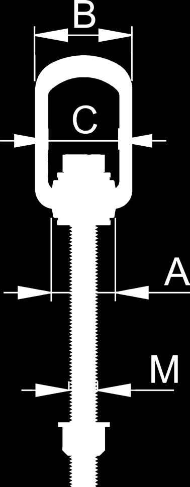
6 Type WLL [t] weight. [kg/pc.] T A ICE-Load ring for bolting Super Rotation metric B C D E F 0.6 t M M H I K L M N SW ISK torque [Nm] Ref. No. 0.9 t M M t M M t M M t M M t M M t M30** M Type WLL ew. T A B C D E F H I K L M N SW ISK torque Ref. No.. ICE-Load ring for bolting Super Rotation metr. longer vario bolt 0.6 t M8 0.6 * M t M * M t M * M t M * M t M * M t M * M t M30** 6.7 * M Table 3: Dimensioning * = weight depends on design specifics ** = bolt with quality grade 10.9 Subject to technical alterations (SW = wrench size / ISK = internal hexagon) 6


7 7
Load Ring for bolting >VLBG<
 RUD-Art.-Nr.: 8500972-EN / 02.016 Load Ring for bolting >< EN Safety instructions This safety instruction/declaration of the manufacturer has to be kept on file for the whole lifetime of the product. Translation
Load Ring bolted > VWBG < in pink
 RUD-Art.-Nr.: 8503693-EN / 03.016 Load Ring bolted > VWBG < in pink EN Safety instructions This safety instruction/declaration has to be kept on file for the whole lifetime of the product. Translation
Load Ring bolted > VWBG < in pink
 RUD-Art.-Nr.: 8503693-EN / 03.014 Load Ring bolted > VWBG < in pink EN Safety instructions This safety instruction/declaration has to be kept on file for the whole lifetime of the product. Translation
VWBG-V LOAD RING. User Instructions - Part 1. Complies with the machinery directives 2006/42/EC. Safety instructions
 Complies with the machinery directives 2006/42/EC NB: Please ensure that the safety instructions have been fully read and understood before initial use of the VWB-V bolt-on lifting point. Failure to do
>IAGH, IMAGH< >VAGH(S), VMAGH(S)<
, VMAGH(S)<") RUD-Art.-Nr.: 7902350-EN / 11.016 >IAGH, IMAGH< >VAGH(S), VMAGH(S)< Assembly instruction This Assembly instruction/declaration of the manufacturer has to be kept on file for the whole lifetime of the product.
RUD-Art.-Nr.: 7902350-EN / 11.016 >IAGH, IMAGH< >VAGH(S), VMAGH(S)< Assembly instruction This Assembly instruction/declaration of the manufacturer has to be kept on file for the whole lifetime of the product.
>IAGH, IMAGH< >VAGH(S), VMAGH(S)<
, VMAGH(S)<") RUD-Art.-Nr.: 7902350-EN / 01.018 >IAGH, IMAGH< >VAGH(S), VMAGH(S)< Assembly instruction This Assembly instruction/declaration of the manufacturer has to be kept on file for the whole lifetime of the product.
RUD-Art.-Nr.: 7902350-EN / 01.018 >IAGH, IMAGH< >VAGH(S), VMAGH(S)< Assembly instruction This Assembly instruction/declaration of the manufacturer has to be kept on file for the whole lifetime of the product.
>PSA-VRS< >PSA INOX STAR< M12 (1 Pers.)
") RUD-Art.-Nr.: 7905318-EN / 02.017 >PSA-VRS< >PSA INOX STAR< M12 (1 Pers.) Safety instructions This safety instruction/declaration of the manufacturer has to be kept on file for the whole lifetime of the
RUD-Art.-Nr.: 7905318-EN / 02.017 >PSA-VRS< >PSA INOX STAR< M12 (1 Pers.) Safety instructions This safety instruction/declaration of the manufacturer has to be kept on file for the whole lifetime of the
>PSA-VRS< >PSA INOX STAR< M12 (1 Pers.)
") RUD-Art.-Nr.: 7905318-EN / 06.018 >PSA-VRS< >PSA INOX STAR< M12 (1 Pers.) Safety instructions This safety instruction/declaration of the manufacturer has to be kept on file for the whole lifetime of the
RUD-Art.-Nr.: 7905318-EN / 06.018 >PSA-VRS< >PSA INOX STAR< M12 (1 Pers.) Safety instructions This safety instruction/declaration of the manufacturer has to be kept on file for the whole lifetime of the
BC Shackle. Made in the China. Alloy Steel Anchor Shackle. Instructions for handling and use - Please read in full before using this device
 BC Shackle Made in the China Alloy Steel Anchor Shackle Instructions for handling and use - Please read in full before using this device Index 1.) Introduction 2.) Warnings / General Use Guidelines 3.)
GUNNEBO INDUSTRIES LIFTING SHACKLES
 GUNNEBO INDUSTRIES LIFTING SHACKLES USER S INSTRUCTIONS AND EC DECLARATION OF CONFORMITY Original instructions according to Directive 2006/42/EC on machinery, section 1.7.4 Instructions, and Annex II.1.A.
Manual winch MANISTOR 100 and 200
 Manual wall winch Manual winch MANISTOR 100 and 200 Instruction manual UK 173-192.10-3 PRODUCT DEVELOPED AND MANUFACTURED ACCORDING TO NF EN 13157 STANDARD REGISTERED DESIGN To ensure the constant improvement
Z5160 Load adapter Mounting instructions (1.2 EN)
") Z560 Load adapter Mounting instructions (. EN) WARNING! CAUTION! IMPORTANT! Note: References in the manual This refers to a potentially dangerous situation which may lead to personal injury. This refers
Z560 Load adapter Mounting instructions (. EN) WARNING! CAUTION! IMPORTANT! Note: References in the manual This refers to a potentially dangerous situation which may lead to personal injury. This refers
Premium PowerPoint Presentation. Rigging Review
 Premium PowerPoint Presentation Rigging Review Chapter 1 Hoisting Safety Review: What about the CG Symmetrical vs. Asymmetrical Balanced and Unbalanced Lifting Lug Hooks Angle Deformation Safety Gates
BRAKE WINCH RUP 503-[T/BT] EQUIPMENT FOR LIFTING LOADS. AT 053-[T/BT] xx
![BRAKE WINCH RUP 503-[T/BT] EQUIPMENT FOR LIFTING LOADS. AT 053-[T/BT] xx](/thumbs/88/115945274.jpg "BRAKE WINCH RUP 503-[T/BT] EQUIPMENT FOR LIFTING LOADS. AT 053-[T/BT] xx") Reference number: BRAKE WINCH RUP 503-[T/BT] EQUIPMENT FOR LIFTING LOADS DESIGNATED USE The brake winch RUP 503-[...]T series is a load lifting / lowering device. Device is equipped with safety brake for
Reference number: BRAKE WINCH RUP 503-[T/BT] EQUIPMENT FOR LIFTING LOADS DESIGNATED USE The brake winch RUP 503-[...]T series is a load lifting / lowering device. Device is equipped with safety brake for
LIFTING PIN VDI3366. Item code: B Use and maintenance manual complete of EC conformity declaration. San Maurizio C.
 Via Quarantelli 8-10077 - San Maurizio C.se - Italy T +39 011 996 46 11 - F +39 011 996 46 46 C.F./P.IVA 07677130010 info@omcr.it - www.omcr.it Use and maintenance manual complete of EC conformity declaration.
ZIPP VUMAQUAD INSTALLATION INSTRUCTIONS
 ZIPP VUMAQUAD INSTALLATION INSTRUCTIONS CAUTION All Zipp Crank and BB products should be installed by a professional bicycle mechanic using the appropriate tools. Zipp assumes no responsibility for damages
Hand winch MANIBOX GR
 Hand spurgear winch Hand winch MANIBOX GR Instruction manual UK 34-331.09/9 PRODUCT DEVELOPED AND MANUFACTURED ACCORDING TO STANDARD NF EN 13157 In an endeavour to improve its products, HUCHEZ reserves
MAINTENANCE AND OPERATING MANUAL
 MAINTENANCE AND OPERATING MANUAL Cyclone condensate separator Type ASA EN EN Maintenance and operating manual Purpose and appropriate use Dear Customer, thank you for choosing our product. In order to
OPERATION AND INSTRUCTION MANUAL Swivel Anchor Model: SWY100N
 OPERATION AND INSTRUCTION MANUAL Swivel Anchor Model: SWY100N IMPORTANT!!! ALL PERSONS USING THIS EQUIPMENT MUST READ AND UNDERSTAND ALL INSTRUCTIONS. FAILURE TO DO SO MAY RESULT IN SERIOUS INJURY OR DEATH.
User Instructions 1789 Parapet Wall Anchor
 User Instructions 1789 Parapet Wall Anchor This manual is intended to meet the Manufacturer Instructions as required by ANSI Z359.1 and should be used as part of an employee training program as required
Installation, operation & maintenance manual - original version
 Installation, operation & maintenance manual - original version AVK gate valves for water and wastewater Series 01, 02, 06, 12, 15, 18, 20, 26, 32, 33, 36, 38, 50, 55 and 636 COPYRIGHT AVK GROUP A/S 2018
1.3 LIMITATIONS: The following application limitations must be recognized and considered before using this product:
 3965 Pepin Avenue Red Wing, MN 55066-1837 Toll Free: (800) 328-6146 Phone: (651) 388-8282 Fax: (651) 388-5065 www.protecta.com User Instruction Manual AJ720A Concrete Anchor This manual is intended to
Erection, maintenance and disposal Inverted installation. Zinc oxide silicone-housed surge arresters PEXLIM R-X, Q-X and P-X
 Erection, maintenance and disposal Inverted installation Zinc oxide silicone-housed surge arresters PEXLIM R-X, Q-X and P-X 1 Important information The following instruction is valid for PEXLIM R-X, PEXLIM
OPERATION AND INSTRUCTION MANUAL Swivel Anchor Model: HD26248
 OPERATION AND INSTRUCTION MANUAL Swivel Anchor Model: HD26248 IMPORTANT!!! ALL PERSONS USING THIS EQUIPMENT MUST READ AND UNDERSTAND ALL INSTRUCTIONS. FAILURE TO DO SO MAY RESULT IN SERIOUS INJURY OR DEATH.
Torque Turn Tests on Q-Slip Sleeve holding down screws Ref: RP/2014 Eng. Jan A
 Torque Turn Tests on Q-Slip Sleeve holding down screws Ref: RP/2014 Eng. Jan - 001-A 5 januari 2014 A High level Look in to the holding forces from a grub-screw locking mechanism Author- Marco Kacgin -
steel wire rope slings and fittings
 steel wire rope slings and fittings Steel Wire Rope Slings SNS7531 Working load limits using 6x19 or 6x36 IWR (1960mpa) SWR Ø nominal break load 1 Leg 2 Leg 3 and 4 Leg angle between the legs angle between
CODA EXPERT CRANK INSTRUCTION MANUAL
 CODA EXPERT CRANK INSTRUCTION MANUAL Congratulations and thanks for your purchase of the new CODA Expert crankset. You have invested in a component which offers light weight, high strength, and stiffness
Operations and Instruction Manual Might Swivel Model # Concrete and Steel Anchorage Connector ANSI Z ,000 lbs / 44kn
 Operations and Instruction Manual Might Swivel Model # 00238 Concrete and Steel Anchorage Connector ANSI Z359.1 10,000 lbs / 44kn Description: Zinc plated forged heat treated steel, Special design gives
1.0 Purpose: To provide guidelines for selection, usage, inspection and rejection of rigging equipment
 Orignal Issue Date : 28-10-10 Date of Revision: Page- - 1-1.0 Purpose: To provide guidelines for selection, usage, inspection and rejection of rigging equipment (Slings & Ropes) 2.0 Reference: 3.0 Associated
OPERATION AND INSTRUCTION MANUAL
 OPERATION AND INSTRUCTION MANUAL Swivel Anchor Model: SWS100N-316-CTS Patent US # 8,424,638 WARNING: ALL PERSONS USING THIS EQUIPMENT MUST READ AND UNDERSTAND ALL INSTRUCTIONS. FAILURE TO DO SO MAY RESULT
Repair instructions. Pivot bushing replacement. XL-AS10001RM-en-DE Rev B
 Repair instructions Pivot bushing replacement XL-AS10001RM-en-DE Rev B Table of contents Table of contents 1 General information... 3 1.1 Safety information...3 1.2 Legal information...4 1.3 Order and
MULTI-MONTI Technical manual
 MUTI-MONTI Technical manual Version 01/2017 Technical manual MUTI-MONTI Content Instructions for fixing P. 3 Chapter 1: Admissible loads in as well as P. 4 anchor characteristics for MMS-6 to MMS-16 1.1
MANUAL SEALLESS STEEL STRAPPING TOOL MODEL A
 OPERATION MANUAL / SPARE PARTS LIST MANUAL SEALLESS STEEL STRAPPING TOOL MODEL A337.0001 13.1912.01 13191201.en/MAS/ 10.02 INDEX PAGE 1 SAFETY INSTRUCTIONS 2 2 WARRANTY CONDITIONS AND LIABILITY 4 3 APPROPRIATE
Technical Manual. Stand 05/2011
 MULTI-MONTI Technical Manual Stan5/2011 Technical Manual HECO-MULTI-MONTI Contents Instructions for fixing P. 3 Chapter 1 : Admissible loads in as well as P. 4 anchor-characteristics for MMS-6 to MMS-16
Operating Instructions VETTER Industrial Lifting Bags 8 bar - Type IKV
 Industrial Pneumatics. Operating Instructions VETTER Industrial Lifting Bags 8 bar - Type IKV Article No. 87015301 Vetter GmbH I 03/12 I Changes and errors excepted. Vetter Industrial Lifting Bags 8 bar
Operating instructions Safety Rope Emergency Stop Switches ZB0052 / ZB0053 ZB0072 / ZB0073
 Operating instructions Safety Rope Emergency Stop Switches UK ZB0052 / ZB0053 ZB0072 / ZB0073 7390878 / 02 03 / 2011 Contents 1 Safety instructions...3 2 Installation / set-up...4 2.1 Applications...4
Marine 6-Boat Free-Standing Racks SKU: Updated November 2011
 Marine 6-Boat Free-Standing Racks SKU: 30-061 Updated November 011 Contains: Marine -Boat Free-Standing Racks (SKU 1-003) Marine 3 rd Boat Expansion Racks (SKU 1-0303) Marine Back Legs (SKU -001) 3 Sets
Name of product: Gripper for vertical façade FTV panels Types: PVF (60, 80, 100, 120, 133, 150, 172, 200 and 240 mm) INSTRUCTIONS FOR USE
 INSTRUCTIONS FOR USE") Name of product: Gripper for vertical façade FTV panels Types: PVF (60, 80, 100, 120, 133, 150, 172, 200 and 240 mm) INSTRUCTIONS FOR USE CONTENTS INTRODUCTION - GENERAL INFORMATION 3 Purpose of instructions
Name of product: Gripper for vertical façade FTV panels Types: PVF (60, 80, 100, 120, 133, 150, 172, 200 and 240 mm) INSTRUCTIONS FOR USE CONTENTS INTRODUCTION - GENERAL INFORMATION 3 Purpose of instructions
// ADapters GUIDelines
 // ADapters GUIDelines ADAPTER SELECTION Selection of an appropriate ALFAGOMMA adapter for a given application depends on the fluid system operating parameters listed below and the tube material and wall
FLOW CONDITIONER «EMIS-VEKTA 1200» EMIS-VEKTA 1200.UM.PS v User manual Passport. «EMIS», CJSC Russia, Chelyabinsk
 EMIS-VEKTA 1200.UM.PS 27.11.2012 v1.0.5 FLOW CONDITIONER User manual Passport www.emis-kip.ru «EMIS», CJSC Russia, Chelyabinsk Disclaimer "EMIS", CJSC reserves the right to make changes in the design and
MSA Latchways Ladder System
 Systems overview 1 of 13 Important information Individuals or organisations carrying out the installation of a MSA Latchways ladder fall protection system shall read, understand and follow these instructions
Operating instruction for the quick-change tap holders type:
 type: HF 20 HF 30 Date of edition: 15.07.2008 Stage of alteration: 4 Please keep this for future use! Contents: 1 Application range, safety instructions and technical data... 3 1.1 Application range,
HELMETS SAVE LIVES!!! ALWAYS WEAR A PROPERLY FITTED HELMET WHEN YOU RIDE YOUR SCOOTER. DO NOT RIDE AT NIGHT. AVOID RIDING IN WET CONDITIONS.
 HELMETS SAVE CORRECT FITTING - MAKE SURE YOUR HELMET COVERS YOUR FOREHEAD. LIVES!!! ALWAYS WEAR A PROPERLY FITTED HELMET WHEN YOU RIDE YOUR SCOOTER. DO NOT RIDE AT NIGHT. AVOID RIDING IN WET CONDITIONS.
Health & Safety Policy and Procedures Manual SECTION 25 RIGGING AND HOISTING EQUIPMENT
 SECTION 25 RIGGING AND HOISTING EQUIPMENT 1. RIGGING AND HOISTING: These rules apply to all Maul Electric, Inc. employees and subcontractors. Note: Maul Electric, Inc. employees will utilize mechanical
MATERIAL HANDLING - FIELD RIGGING SAFETY PROGRAM
 Title: Material Handling - Rigging Effective Date: 12/4/2014 Control Number: THG_0049 Revision Number: 1 Date: 10/23/2015 Annual Review Completed: 5/13/2015 MATERIAL HANDLING - FIELD RIGGING SAFETY PROGRAM
Instruction Manual Contact Pressure Vacuum Gauge
 MS10 Instruction Manual Contact Pressure Vacuum Gauge Table of Contents 1. Safety Instructions 2. Intended Applications 3. Product Description and Functions 4. Installation 5. Commissioning 6. Maintenance
SASK-A-POLE OWNERS AND USERS MANUAL
 SASK-A-POLE OWNERS AND USERS MANUAL GENERAL INFORMATION The Saskatchewan Abilities Council s Sask-a-Pole accessibility and transfer aid is designed to help provide safe and easy access to chairs, beds,
Instructions for Use Wire Rope Hoist SAT 08 / SAT 16 / SAT 32
 Instructions for Use Wire Rope Hoist SAT 08 / SAT 16 / SAT 32 Item no. Load-carrying capacity (payload) Rope diameter Weight without rope Device dimensions SAT 08 800 kg SAT 16 SAT 32 Rope advance per
Design Guide MSW from M20 to M70. Original version of the design guide
 Page 1 of 11 Original version of the design guide For Series Components Spieth locknuts (precision locknuts) MSW 20.28 MSW 20.40 MSW 25.28 MSW 25.40 MSW 30.28 MSW 30.44 MSW 35.28 MSW 35.44 MSW 40.28 MSW
RESCUE LIFTING DEVICE RUP 503-[...] AT 053-[...] xx
![RESCUE LIFTING DEVICE RUP 503-[...] AT 053-[...] xx](/thumbs/90/102827869.jpg "RESCUE LIFTING DEVICE RUP 503-[...] AT 053-[...] xx") EN 1496:2006 / B Reference number: RESCUE LIFTING DEVICE RUP 503-[...] AT 053-[...] xx DESIGNATED USE The rescue lifting device RUP 503-[...] series is a component of rescue system. Using this device the
EN 1496:2006 / B Reference number: RESCUE LIFTING DEVICE RUP 503-[...] AT 053-[...] xx DESIGNATED USE The rescue lifting device RUP 503-[...] series is a component of rescue system. Using this device the
ALTERNATOR RACKS 135, 170 & 190 INSTRUCTIONS
 Figure A Item # Description Quantity 1 Alternator Rack 1 1 3 4 11 5 10 8 2 Lower Mount Kit (see detail) 2 3 16mm M5 Swivel-Mount Bolt 2 4 M7 Washer 2 5 M6 Lock Nut 2 6 Lock Washer 2 7 Swivel Mount 2 8
INSTRUCTIONS & MAINTENANCE SHEET PORTABLE HYDRAULIC PUNCHING HEAD PH045
 INSTRUCTIONS & MAINTENANCE SHEET PORTABLE HYDRAULIC PUNCHING HEAD PH045 V05.2013 DECLARATION OF CONFORMITY 2 1. TECHNICAL CHARACTERISTICS Maximum punching capacity: Min / Max. hole diameter: Max. yield
Chain slings Operating manual
 Chain slings Operating manual Please keep this instruction manual for further use This manual must be read and understood before operating the chain sling 1 Summary Page 1 Chain sling selection 3 1.1 General
IMPORTANT: RECEIVING INSTRUCTIONS:
 Instruction Sheet Sidewinder Mechanical Bender IMPORTANT: RECEIVING INSTRUCTIONS: Visually inspect all components for shipping damage. If any shipping damage is found, notify carrier at once.shipping damage
Telefon (+45) Telefax (+45)
 Telefax (+45)") Uni-Valve A /S VENTILER & INSTRUMENTER Telefon (+45) 43 43 82 00 Telefax (+45) 43 43 74 75 mail@uni-valve.com www.uni-valve.com UNI-S83 / S84 3/4-way ball valve Installation and Operating manual 3/4-WAY
Uni-Valve A /S VENTILER & INSTRUMENTER Telefon (+45) 43 43 82 00 Telefax (+45) 43 43 74 75 mail@uni-valve.com www.uni-valve.com UNI-S83 / S84 3/4-way ball valve Installation and Operating manual 3/4-WAY
OPERATOR S MANUAL SPREADER. CSS, VNQ [For Combine Harvester AW82V] Original instructions
![OPERATOR S MANUAL SPREADER. CSS, VNQ [For Combine Harvester AW82V] Original instructions](/thumbs/90/102423265.jpg "OPERATOR S MANUAL SPREADER. CSS, VNQ [For Combine Harvester AW82V] Original instructions") OPERATOR S MANUAL SPREADER CSS, VNQ [For Combine Harvester AW82V] en Original instructions Introduction Introduction Please read this operator s manual before using your spreader. We would first like to
OPERATOR S MANUAL SPREADER CSS, VNQ [For Combine Harvester AW82V] en Original instructions Introduction Introduction Please read this operator s manual before using your spreader. We would first like to
Cautions : 1. Clogging of the element raises resistance to exhaust, thus lowering the
 The Silencer, connected to the exhaust port of a device, suppresses the exhaust noise. The Silencer displays an excellent noise suppression effect. Three types are available for your selection. The element
Operating manual Mobile Man Anchor IM-200 Reference No. IM 200
 Operating manual Mobile Man Anchor IM-200 Reference No. IM 200 EN 795:1996 class E Table of contents: 1. Description of the Mobile Man Anchor... 2 2. Construction of the Mobile Man Anchor.... 3 3. Technical
Flow controller Type ED/CCB311 Instruction manual
 Flow measurement Flow controller Type ED/CCB311 1. GENERAL DESCRIPTION page 4 2. DETAILED DESCRIPTION page 4 3. PIPE - EXPLOITATION page 5 4. PREVENTIVE MAINTENANCE page 5 5. REPLACEMENT OF THE CONTACT
Assembly, Installation and operating. instructions for. Söll-Xenon anchorage device
 Assembly, Installation and operating instructions for Söll-Xenon anchorage device according to EN 795:1996 Part No: XE-... (The following must be completed by the operator in permanent waterproof ink.)
OPERATING INSTRUCTIONS (Translation) Rope winch Type KWE 250 KWV 300 KWE 650 KWV 650 KWE 1000 KWV 1250
 Rope winch Type KWE 250 KWV 300 KWE 650 KWV 650 KWE 1000 KWV 1250") 1. User groups Duties Operator Operation, visual inspection Specialist personnel Assembly, disassembly, repair, maintenance Tests OPERATING INSTRUCTIONS (Translation) Rope winch Type KWE 250 KWV 300 KWE
1. User groups Duties Operator Operation, visual inspection Specialist personnel Assembly, disassembly, repair, maintenance Tests OPERATING INSTRUCTIONS (Translation) Rope winch Type KWE 250 KWV 300 KWE
2-finger parallel gripper KTG 50
 Translation of the original manual 2-finger parallel gripper KTG 50 Assembly and operating manual Superior Clamping and Gripping Imprint Imprint Copyright: This manual remains the copyrighted property
Guide to Documentation and Marking Part 5 Lifting Accessories, Slings
 Guide to Documentation and Marking Part 5 Lifting Accessories, Slings Document reference LEEA 059-5 version 1 dated 31.07.14 Introduction. This guide is aimed at manufacturers, distributors and users of
Rapidmain Installation Guide
 Rapidmain Installation Guide Aluminium Compressed Air Pipe Work Installation Guide Trafalgar Court, Waterloo Ind Estate, Widnes Cheshire. UK. Ref: Rapidmain installation guide 4b Index 1. Rapidmain fittings:
F13.11 PARALLEL HINGES F13 PROJECT-OUT WINDOWS AND TOP HUNG WINDOWS
 F13 PROJECT-OUT WINDOWS AND TOP HUNG WINDOWS F13.11 01.06.2018 Waregemstraat 5-9870 Zulte - Belgium - T. +32 9 388 88 81 - F. +32 9 388 88 21 - commercial@sobinco.com - www.sobinco.com CONTENTS 1. General...F13.11.03
CFSW. Hinges with built-in safety multiple switch
 CFSW. Hinges with built-in safety multiple switch ELESA Original design Elesa Standards Main dimensions Fitting Weight Code Description L B f ±0.2 f 1 ±0.2 H h 1 h 2 d 3 d 4 C [Nm]# g 426601 CFSW.110-6-2NO+2NC-C-A
Cautions : 1. Be careful when you release the Stop Fitting with some internal pressure
 The flow-shut mechanism will operate to stop the air flow when the tube is disconnected and will allow air flow when the tube is connected. The double-passage structure facilitates easy connection and
Hand winch MANIBOX VS
 Hand wormgear winch Hand winch MANIBOX VS Instruction manual UK -.09/ PRODUCT DEVELOPED AND MANUFACTURED ACCORDING TO STANDARD NF EN INSTRUCTION MANUAL FOR COMMISSIONING AND MAINTENANCE In an endeavour
Assembly, disassembly and user manual
 Assembly, disassembly and user manual D000A Product description: Plate-forme individuelle roulante légère "PIRL" (Lightweight rolling individual platform) compliant with norm NF P 9-. Single operator use.
Assembly instruction. Operating temperature range -60 C +85 C Protection. IP 66, 67, 68 (5 bar)
") Assembly instruction 1 2 3 4 5 6 7 1. Entry Component 2. Compound Sleeve 3. Interlocking Armour Cone 4. Armour Clamping Ring 5. Gland Body 6. Outer Sheath Sealing 7. Dome Nut 8. Compound 8 Operating temperature
Assembly instruction 1 2 3 4 5 6 7 1. Entry Component 2. Compound Sleeve 3. Interlocking Armour Cone 4. Armour Clamping Ring 5. Gland Body 6. Outer Sheath Sealing 7. Dome Nut 8. Compound 8 Operating temperature
M S I C R A N E S C A L E
 2 M E A S U R E M E N T S Y S T E M S I N T E R N A T I O N A L Table of Contents Forward...3 Safe Operating Guidelines...4 Operating Suggestions...4 Handling Hoist Motion...4 Safe Loading and Rigging
Product Name: O-Torque Beamer
 Product Name: O-Torque Beamer Part #: 00141 Instruction Manual Do not throw away these instructions! Read and understand these instructions before using equipment! Introduction 1 Applicable Safety Standards
EZee Glider Manual. Tools needed for Assembly: Wrench (included) Philips Screwdriver (not included) Assembly Instructions
 Philips Screwdriver (not included) Assembly Instructions") EZee Glider Manual Congratulations on your purchase of the EZee Glider! Your glider is designed for years of nearly carefree use by your child. These instructions include how to set up your glider and
EZee Glider Manual Congratulations on your purchase of the EZee Glider! Your glider is designed for years of nearly carefree use by your child. These instructions include how to set up your glider and
ABS lifting unit 2,3 kn
 1 597 0533 GB 04.2014 en Installation and Operating Instructions Translation fro original instruction www.sulzer.co Installation and Operating Instructions for (for DL6151113) 2 Sulzer reserves the right
White Industries Crank Installation Instructions
 White Industries Crank Installation Instructions Follow these instructions to install both ENO and VBC crank arms and chain rings. When the ENO crank is installed on a 113x68mm bottom bracket, the Q factor
Declaration of Conformity as per Directive 97/23/EC
 Declaration of Conformity as per Directive 97/23/EC The manufacturer declares that:, 47906 Kempen, Germany Continuous, inline sampling valves Series 27f, with packing Operate with either; Star lever, or
CORPORATE SAFETY MANUAL
 CORPORATE SAFETY MANUAL Procedure No. 32-0 Revision: Date: May 2005 Total Pages: 10 PURPOSE To provide general guidelines for the inspection of all ropes, chains, cables, slings, etc. used for personnel
CRANKSET 1 - TECHNICAL SPECIFICATIONS 2 - COMPATIBILITY CHAIN LINE SIZE 52/39 53/39 55/42 54/42 50/34 52/36. Ultra - torque 11s ULTRA-TORQUE
 ULTRA-TORQUE 1 - TECHNICAL SPECIFICATIONS STANDARD BOLT CIRCLE DIAMETER CHAIN LINE MINIMUM CHAINSTAY LENGHT AXLE THREADS 52/39 53/39 55/42 54/42 COMPACT BOLT CIRCLE DIAMETER CHAIN LINE MINIMUM CHAINSTAY
GENERAL GUIDELINES FOR PROPER RIGGING PRACTICES AND INSPECTION & REMOVAL CRITERIA FOR SLINGS PER OSHA
 GENERAL GUIDELINES FOR PROPER RIGGING PRACTICES AND INSPECTION & REMOVAL CRITERIA FOR SLINGS PER OSHA 1910.184 SAFE OPERATING PRACTICES -.Whenever any sling is used, the following practices shall be observed:
ATOM-X 2. User Manual
 1.0 Installation, Use, Compatibilty & Warning! 2.0 Introduction to & Scope of Use Page 2 Index Page 3 4 3.0 Storage, Issue & Inspection 4.0 Quality, Legislation & Exclusions 5.0 Record card 5 6 7 Description/Explanation
Instruction Manual. Alfa Laval SB Membrane Sample Valve ESE02963-EN Original manual
 Instruction Manual Alfa Laval SB Membrane Sample Valve ESE02963-EN2 2016-02 Original manual Table of contents The information herein is correct at the time of issue but may be subject to change without
engineered products Foldable Topside Creeper Safety First VIDEO INSTRUCTIONS ARE AVAILABLE ON OUR WEBSITE AT:
 engineered products Foldable Topside Creeper Please read and understand all safety advisories and operating instruction in this manual to ensure safe and productive operation of your new Topside Creeper.
Coiling Tube with Twist-Proof Fitting
 http://www.pisco.co.jp FITTING CONTROLLER VALVE TUBE MAKE-TO-ORDER PRODUCTS Push-In Fitting Type Anti-Twisting Coiling Tube for Air Tool Coiling Tube with Twist-Proof Fitting 306 Avoid Twisted Tube Problem
USER INSTRUCTION MANUAL CONCRETE BOLT ANCHORAGE CONNECTOR
 Instructions for the following series products: Concrete Bolt Connector Models: 2100041, 2100066, 2104560, 2104561, 2104562 USER INSTRUCTION MANUAL CONCRETE BOLT ANCHORAGE CONNECTOR This manual is intended
CFSW. Hinges with built-in safety multiple switch
 CFSW. Hinges with built-in safety multiple switch ELESA Original design technical informations Material - Hinge body: self-extinguish high-rigidity SUPER-technopolymer, black colour. Resistant to solvents,
3-PIECE BALL VALVE, 3600 PSI/ PN 248, WITH ISO DIRECT MOUNTING PAD 306M SERIES/ PED Category II
 3-PIECE BALL VALVE, 3600 PSI/ PN 248, WITH ISO DIRECT MOUNTING PAD 306M SERIES/ PED Category II 306M User Manual English Version Use for company in Europe who will place the product on the market, please
(1) Type (2) Thread size (T) (3) Wrench size specification : inch spec. (NPT, UNF) : mm spec. (M, R)
 Type (2) Thread size (T) (3) Wrench size specification : inch spec. (NPT, UNF) : mm spec. (M, R)") This exhaust needle valve, which comes with silencer, controls the exhaust flow rate. The valve can be attached directly to a solenoid valve where a cylinder or like mechanism has no sufficient space around
This exhaust needle valve, which comes with silencer, controls the exhaust flow rate. The valve can be attached directly to a solenoid valve where a cylinder or like mechanism has no sufficient space around
OMG Southeast & Southwest RIGGING SAFETY PROGRAM (29 CFR Part , , , , , & ANSI B30.5, ANSI B30.
 OMG Southeast & Southwest RIGGING SAFETY PROGRAM (29 CFR Part 1926.251, 1926.550, 1910.180, 1910.184, 1910.330, & ANSI B30.5, ANSI B30.8) Nearly every project is required to perform some type of rigging
Instruction Manual. AlfaLavalSBAntiVacuumValve ESE02960-EN Original manual
 Instruction Manual AlfaLavalSBAntiVacuumValve ESE02960-EN3 2017-11 Original manual Table of contents The information herein is correct at the time of issue but may be subject to change without prior notice
Neotecha SAPRO - Aseptic sampling valve SV Installation, operation and maintenance instructions
 Before installation these instructions must be fully read and understood 2 Safety Please read these instructions carefully. 2.1 General danger potential Not paying attention to this instruction Incautious
Translation of the original Operating Instructions for HKS rubber compensators
 Because of their flexible elements and mechanisms, HKS rubber compensators are susceptible to damage of all types and adverse loads in operation. For reliable operation of a compensator and, thus, the
Push-In Fitting Type Silencer
 http://www.pisco.co.jp CONTROLLER VALVE TUBE MAKE-TO-ORDER PRODUCTS Push-In Fitting Type 540 Reduce Exhaust Noise from Exhaust Port. Excellent Silencing Effect. Selection from 3 types. Push-In Fitting
Operating instructions. Pressure container, 50 litre capacity, for operating pressures of 2.5 and 6 bar. Doc-315 Rev. 0
 Operating instructions Pressure container, 50 litre capacity, for operating pressures of 2.5 and 6 bar Doc-315 Rev. 0 CONTENTS 1 USE FOR INTENDED PURPOSE...2 2 GENERAL SAFETY NOTES...2 3 INSPECTION BY
Agilent 1220 Infinity II LC Mobile Upgrade Kit
 Agilent 1220 Infinity II LC Mobile Upgrade Kit Note 1220 Infinity II LC Mobile Upgrade Kit This note describes the procedures to install an Mobile Upgrade kit to an existing Agilent 1220 Infinity II LC.
Declaration of Conformity as per Directive 97/23/EC
 Declaration of Conformity as per Directive 97/23/EC The manufacturer declares that:, 47906 Kempen, Germany Discontinous, inline sampling valves Series 27a and Series 27g, with packing with lever (180 )
The Powerful Sealing Calculation
 KLINGER expert 6.0 The Powerful Sealing Calculation The KLINGER expert 6.0 gasket design program is a versatile software to assist users in the selection of non-metallic gasket materials. www.klinger.co.at
20 Ton SD Shop Press Operating Instructions
 20 Ton SD Shop Press Operating Instructions MODEL NO. 850SD Hazard Symbols Used in the Manuals This manual includes the hazard symbols defined below when the operations or maintenance job involves a potential
Instructions for Use. Plug connection for medical gas and vacuum acc. to DIN / 2004 DIN EN ISO
 Instructions for Use Plug connection for medical gas and vacuum acc. to DIN 13260-2 / 2004 DIN EN ISO 9170-1 Table of Contents Page 1. MANUFACTURER S DATA... 3 2. INTRODUCTION... 4 3. APPLICATION... 5
User Instruction Manual
 User Instruction Manual Dual Sliding Beam Anchor Model # GF-DSBA-BA01202 Model # GF-DSBA-BA01802 Model # GF-DSBA-BA02402 WWW.GFORCE-SAFETY.COM Tacklestore Ltd Unit R1D Rockingham Gate Cabot Park, Poplar
PHOENIX, ARIZONA USA
 NEW PRODUCTS MODEL: US-AASS-80 DESCRIPTION: Cantilever Arm 80 MEETS OSHA & ANSI Z359.14 CLASS B 1-800-850-5914 PHOENIX, ARIZONA USA WWW.ULTRASAFEUSA.COM CANTILEVER ARM The Ultra-Safe cantilever arm has