Stuart River Preliminary HDD Feasibility Assessment Report
|
|
|
- Miranda Wilcox
- 5 years ago
- Views:
Transcription

1 Stuart River Preliminary HDD Feasibility Assessment Report 08C7138-PL-RPT-0006, Rev Jun-2010 Enbridge Northern Gateway Project WorleyParsons Canada Services Ltd. Calgary Division 400, Southport Road SW Calgary, Alberta T2W 4X9 Canada Telephone: Facsimile: Copyright 2010 WorleyParsons
2
3 ENBRIDGE NORTHERN GATEWAY PROJECT STUART RIVER PRELIMINARY HDD FEASIBILITY ASSESSMENT REPORT EXECUTIVE SUMMARY This Stuart River Preliminary HDD Feasibility Assessment Report (this report) was prepared by WorleyParsons Canada Services Ltd. (WorleyParsons) for Northern Gateway Pipelines Inc. (Northern Gateway) in support of a regulatory application for approval to construct and operate the Enbridge Northern Gateway Project (the Project). This report discusses the feasibility of using a horizontal directional drilling (HDD) construction technique to cross the Stuart River. Based on a review of the available geological and / or geotechnical information, site visits, site photos and ground profiles, an HDD technique appears to be a feasible crossing method. This crossing will require a detailed survey and geotechnical investigations during detailed engineering to further assess the feasibility of an HDD and to prepare the detailed designs. The contingency plan is to cross the Stuart River using an alternative trenchless crossing method. 08C7138-PL-RPT-0006 Page iii
4 ENBRIDGE NORTHERN GATEWAY PROJECT STUART RIVER PRELIMINARY HDD FEASIBILITY ASSESSMENT REPORT TABLE OF CONTENTS EXECUTIVE SUMMARY...III 1. INTRODUCTION Purpose Project Description Terminology HORIZONTAL DIRECTIONAL DRILLING DESIGN STUART RIVER (SITE NO. 3076) PRELIMINARY DESIGN Site Location and Access Details Route Revision R Centerline Alignment Design Profile and Parameters Design Considerations for the 914 mm (NPS 36) and 508 mm (NPS 20) Pipe Drilling Schedule Contingency Plans CONCLUSIONS...10 REFERENCES...11 APPENDIX A: APPENDIX B: ABBREVIATIONS...12 LIST OF ATTACHMENTS...13 LIST OF FIGURES Figure 1: Overview Map Showing the Locations of the Project Facilities...3 LIST OF TABLES Table 1: Stuart River Crossing Location C7138-PL-RPT-0006 Page iv
5 ENBRIDGE NORTHERN GATEWAY PROJECT STUART RIVER PRELIMINARY HDD FEASIBILITY ASSESSMENT REPORT 1. INTRODUCTION This Stuart River Preliminary HDD Feasibility Assessment Report (this report) was prepared by WorleyParsons Canada Services Ltd. (WorleyParsons) for Northern Gateway Pipelines Inc. (Northern Gateway) under the Enbridge Northern Gateway Project (the Project). The pipelines will cross approximately 773 identified watercourses having defined bed and banks. An initial screening process identified 83 of these crossings requiring more detailed review to determine the preferred crossing method. Currently, the horizontal directional drilling (HDD) method is the preferred crossing method for the Stuart River. This report has been prepared to comply with the National Energy Board (NEB) filing requirements regarding proposed HDD crossings, specifically to provide a preliminary feasibility report detailing the assessment that was done to determine that HDD could be successfully completed and a description of the contingency plan to be used if the HDD is not successful. 1.1 Purpose This report discusses the feasibility of using a horizontal directional drilling trenchless construction technique to cross the Stuart River. Based on a review of existing geological and / or geotechnical information where available, site visits, site photos and ground profiles, an HDD technique appears to be a feasible crossing method. This crossing will require a detailed survey and geotechnical investigations to further assess the feasibility of an HDD and to prepare the detailed designs. The location of the crossing with respect to the pipeline alignment is shown in Table 1. Table 1: Stuart River Crossing Location Crossing Site No. KP (Rev. R) Province Stuart River BC 08C7138-PL-RPT-0006 Page 1
6 ENBRIDGE NORTHERN GATEWAY PROJECT STUART RIVER PRELIMINARY HDD FEASIBILITY ASSESSMENT REPORT 1.2 Project Description Northern Gateway Pipelines Inc. (Northern Gateway), a subsidiary of Enbridge Pipelines Inc., initiated the regulatory phase of the Enbridge Northern Gateway Project (the Project) to obtain regulatory approvals for the Project. The Project is being developed to provide pipelines and associated facilities for the transportation of approximately 83,400 m 3 /d (525,000 bbl/d) of oil from Bruderheim, Alberta to Kitimat, British Columbia and the transportation of approximately 30,700 m 3 /d (193,000 bbl/d) of condensate from Kitimat to Bruderheim. The Project includes the following major components: an oil pipeline, 914 mm OD (NPS 36), approximately 1172 km long extending from the outlet of the Bruderheim station to the Kitimat Terminal a condensate pipeline, 508 mm OD (NPS 20), approximately 1172 km long, located in the same right-of-way as the oil pipeline, extending from the Kitimat Terminal to the Bruderheim Station the Bruderheim Station, consisting of the oil initiating pump station and the condensate receiving facilities eight intermediate pump stations located at intervals along the pipelines two tunnels, approximately 6.5 km and 6.6 km long, to route the oil and condensate pipelines between the Clore River and Hoult Creek valleys the Kitimat Terminal which will comprise the following: o o o o a tank terminal including oil tanks, condensate tanks and associated infrastructure a marine terminal including two tanker berths and one utility berth an initiating condensate pump station oil receiving facilities For an overview map showing the locations of these project facilities, see Figure 1. 08C7138-PL-RPT-0006 Page 2
7 ENBRIDGE NORTHERN GATEWAY PROJECT STUART RIVER PRELIMINARY HDD FEASIBILITY ASSESSMENT REPORT Figure 1: Overview Map Showing the Locations of the Project Facilities 08C7138-PL-RPT-0006 Page 3
8 ENBRIDGE NORTHERN GATEWAY PROJECT STUART RIVER PRELIMINARY HDD FEASIBILITY ASSESSMENT REPORT 1.3 Terminology Appendix A lists abbreviations used in this report. 08C7138-PL-RPT-0006 Page 4
9 ENBRIDGE NORTHERN GATEWAY PROJECT STUART RIVER PRELIMINARY HDD FEASIBILITY ASSESSMENT REPORT 2. HORIZONTAL DIRECTIONAL DRILLING DESIGN Horizontal Directional Drilling (HDD) is a trenchless crossing technique widely used for the installation of pipelines below watercourses, as well as below other infrastructure such as railways, highways and foreign pipelines. Under appropriate conditions, the HDD technique is practical for installations up to about 2,000 m long for the pipeline diameter ranges under consideration on the Project. The Stuart River crossing, at a horizontal length of 689 metres and with pipe diameters of 914 mm OD (NPS 36) and 508 mm OD (NPS 20), falls within current practical length limits. The feasibility of HDD rests primarily upon the geotechnical conditions encountered at a particular site. Other critical factors are suitable topography and availability of temporary workspace for laydown of the makeup section of pipeline. The HDD design for a 914 mm OD (NPS 36) steel heavy wall pipe requires a preliminary design bend radius of at least 1,100 m. The entry and exit angles range from 12 to 16 and minimum entry and exit tangent lengths are 50 m. This basic limiting geometry, site topography, the no-drill zone (NDZ) established by the geotechnical engineer and other drilling and construction requirements will determine, in most cases, the overall length of the HDD. For this Project, the minimum practical length will be about 500 m (depending on topography and the results of the final geotechnical investigations). The geotechnical engineer s report will typically specify the extent and shape of a NDZ as a guide for the HDD design engineer. The NDZ includes an assessment of the drill profile required both to prevent release of drilling fluids to the ground surface during drilling and to avoid potential zones of slope instability. An HDD profile will be a minimum of 10 m below a watercourse and could be substantially deeper. The minimum drill depth below surface to prevent release of drilling fluid to the surface is dependent on hydrostatic mud pressures and the permeability and strength of overlying soil and rock. Generally, most HDD crossings are drilled with the entry point on the low elevation side to minimize the fluid pressure in the pilot hole while maximizing fluid return to the drill rig. Drilling fluid, typically made up of bentonite and water, is cleaned of drill cuttings at the drill rig and then reused in the drilling process. Since full circulation of drilling fluids is not possible in permeable soils such as coarse sand and gravel, steel pipe casing driven through the surficial sand and gravel materials is used to isolate and seal the drill bore profile from these porous materials. Typically, casing is sealed into a lower competent soil or rock. 08C7138-PL-RPT-0006 Page 5
10 ENBRIDGE NORTHERN GATEWAY PROJECT STUART RIVER PRELIMINARY HDD FEASIBILITY ASSESSMENT REPORT 3. STUART RIVER (SITE NO. 3076) PRELIMINARY DESIGN 3.1 Site Location and Access Details The Stuart River crossing is located at KP approximately 4 km south of Fort St. James, B.C, (see Attachment 1 in Appendix B). The north end of Stuart River Provincial Park is located approximately 4 km south of the proposed crossing area. The Stuart River flows south from Stuart Lake through a deep V-shaped canyon mostly incised into a broad, in-filled glacial meltwater channel (Stuart Valley) that extends several kilometres east and west of the river. The Stuart Valley is over 20 km wide in total, and includes the Necoslie River east of the Stuart River. The proposed pipeline crossing runs from just south of the local airport on the west side of the river, in a north-easterly direction and crossing the river at an angle of about Route Revision R Centerline Alignment The centreline alignments up to and including Route Rev. R were chosen based on the use of an HDD method of construction. An alignment based on this method typically allows sufficient length for the construction of an HDD. However, the proposed alignment is generally at the same location and crosses the river at an angle of about 45. This alignment also allows for a contingency crossing along the proposed reroute. The proposed HDD alignment is shown in Attachment 2 (see Appendix B) and is not coincident with the Route Rev. R centreline. The HDD has a horizontal crossing length of 689 m. A minor route revision is recommended to align with the HDD alignment. 08C7138-PL-RPT-0006 Page 6
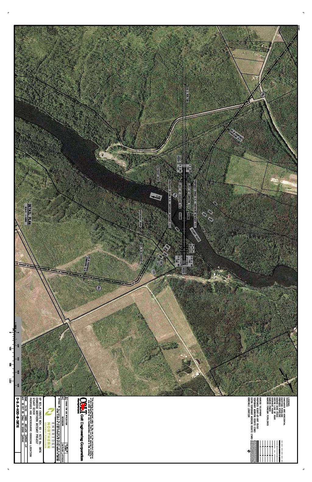
11 ENBRIDGE NORTHERN GATEWAY PROJECT STUART RIVER PRELIMINARY HDD FEASIBILITY ASSESSMENT REPORT 3.3 Design Profile and Parameters One preliminary HDD design drawing has been prepared (see Attachment 3 in Appendix B) for both the 914 mm OD (NPS 36) and the 508 mm OD (NPS 20) watercourse crossings. The preliminary radius of curvature used on the HDD design drawing for both pipes is 1,100 m, the industry standard for 914 mm OD (NPS 36) pipe. The design of the 508 mm OD (NPS 20) pipe crossing will be reviewed during detailed engineering, when site-specific geotechnical and survey information is available. A smaller design radius, in the range of about 600 m is feasible for the 508 mm OD (NPS 20) pipe which can potentially result in a shorter HDD drill length, depending on the detailed subsurface conditions and the joint design considerations of the two pipelines. The entry and exit angles for the 508 mm OD (NPS 20) HDD can be increased compared to the 914 mm OD (NPS 36) pipe, providing additional flexibility in the final design of the drill profile. The two crossings are proposed to be within a common 25-m wide right-of-way (ROW). Within the ROW, the current plan proposes that the HDDs for the two parallel pipelines will have a horizontal separation distance of 15 m. Additional workspace is needed on the entry side of the drill. The drawings show a 50 m by 60 m combined temporary working rights (TWR) space and ROW area at the entry and a 35 m by 20 m combined space on the exit side. This space is required for the rig setup and for the required work at the entry and exit sites. Additional workspace may be required at entry and exit for various construction and topographic considerations. This HDD assessment is preliminary, pending more detailed site survey and geotechnical information. 3.4 Design Considerations for the 914 mm (NPS 36) and 508 mm (NPS 20) Pipe The crossing location has been visited on a number of occasions for route selection purposes. Geotechnical information for the Stuart River crossing is contained in the report Preliminary Geotechnical HDD Feasibility Assessment Stuart River (Crossing #3076). This report contains results of a review of the existing geological information as well as observations made during the site visits. The report also provides preliminary NDZ recommendations. Based on the centreline Route Rev. R alignment and the geotechnical recommendations a preliminary crossing design has been carried out. Three drawings have been prepared for the crossing: Preliminary Proposed HDD Crossing Watercourse Location D-5.8-HDD-3076 (see Attachment 2 in Appendix B) 08C7138-PL-RPT-0006 Page 7
12 ENBRIDGE NORTHERN GATEWAY PROJECT STUART RIVER PRELIMINARY HDD FEASIBILITY ASSESSMENT REPORT Preliminary Proposed HDD Watercourse Crossing D-5.8-HDD-3076R (see Attachment 3 in Appendix B) Hydrofracture Analysis D-5.8-HDD-3076R-HYD (see Attachment 4 in Appendix B) As shown on the proposed HDD crossing drawing, the preliminary proposed drill path will be about 696 m long. The total heavy wall pipe length will be 729 m, including an additional 33 m to allow for the tie-ins. The pipe will cross the Stuart River at a depth of about 50 m below the higher ground surface elevation on the southwest side of the crossing. The deepest point below the riverbed will be 30.5 m. The pipe will enter and exit the ground at an angle of 12. The entry and exit locations are setback from the centre of the river by approximately 280 m and 409 m respectively. The northeast side has been selected as the entry side as it is more or less 12 m lower in elevation than the southwest side. The makeup section will be strung out on the exit side, or southwest side. Additional TWR will be required to lay out the makeup section in a relatively straight line at exit side. Because the HDD alignment is not within the pipeline ROW near exit, it will not be possible to place the makeup area along the existing Route Rev. R alignment. Existing road ROWs and clear-cuts will be used where possible. The hydrofracture calculation curve is shown on the drawing in Attachment 4 (see Appendix B). This drawing demonstrates that the drill profile provides sufficient depth to minimize the risk of fluid release to the surface based on the preliminary parameters chosen for the design. It is typical for this drawing to be used by the drilling contractor in conjunction with a required annular pressure monitoring tool to control the potential for drilling fluid release and loss of drill fluid circulation Casing may be planned for the entry side. The requirement for casing on the exit side will be reviewed during detailed design when subsurface information is available. If casing is required on both sides of the crossing to penetrate sand and gravel, then a drill intersect will most likely be required. Casing size is anticipated to be a minimum of 1372 mm (NPS 54) in diameter with a minimum of 19 mm wall thickness for the NPS 36 pipeline. If telescoping of the casing is required, then the initial casing size may be 1524 mm (NPS 60) or greater with a wall thickness of about 25.4 mm. Casing will be suitably sized for the NPS 20 pipeline. 3.5 Drilling Schedule Construction of the 914 mm OD (NPS 36) crossing may require a schedule of four months of drilling excluding time to install casing. The 508 mm OD (NPS 20) pipe may require a drilling schedule of up to three and a half months. A total time of approximately seven and a half months will be required to complete back-to-back drills. Consideration may be given to drilling the two crossings simultaneously, within the timeframe required for the larger drill. HDD construction activities will include clearing, 08C7138-PL-RPT-0006 Page 8
13 ENBRIDGE NORTHERN GATEWAY PROJECT STUART RIVER PRELIMINARY HDD FEASIBILITY ASSESSMENT REPORT grading, mobilization, casing installation, pilot hole drilling, reaming, product pipe pull, demobilization and site restoration. The calculations in Attachment 5 (see Appendix B) show that the pull loads are estimated to be 443,000 lb (excluding buoyancy control). The pull force for the 914 mm OD (NPS 36) pipe with buoyancy water reduces to about 177,000 lb. Assuming the same drill length the pull force calculated for the 508 mm OD (NPS 20) pipe is 196,000 lb. without buoyancy control and 95,000 lb. with buoyancy control. Buoyancy control should be considered for the two drills to minimize the pull loads and drill rig size requirements. The location of the proposed HDD crossing should allow for drilling to occur in either winter or summer. Year round access is preferable and would eliminate the need to drill the 508 mm OD (NPS 20) and 914 mm OD (NPS 36) simultaneously, although this could be an option for the HDD contractor. If drilling is only possible in a single season then the crossings would need to be drilled simultaneously. Detailed design will include a review of the temporary working rights at entry to ensure that sufficient room is available for two drill rigs to be working on site simultaneously. The elevation difference between entry and exit dictates the two HDDs need to be drilled from the same side. However, it is anticipated that the 508 mm OD (NPS 20) drill path can be designed to allow the entry points to be staggered. Additional workspace will be required for a simultaneous drill. 3.6 Contingency Plans If, during detailed engineering, the HDD crossing method is determined to be not feasible, or if the attempted HDD installation fails, the contingency method of pipeline installation at the Stuart River is an alternative trenchless crossing method. Identification and evaluation of this alternative trenchless crossing method will be completed during detailed engineering 08C7138-PL-RPT-0006 Page 9
14 ENBRIDGE NORTHERN GATEWAY PROJECT STUART RIVER PRELIMINARY HDD FEASIBILITY ASSESSMENT REPORT 4. CONCLUSIONS Based on the available data and information, the preliminary assessment indicates that an HDD crossing of the Stuart River is feasible at this location for both the 508 mm OD (NPS 20) and 914 mm OD (NPS 36) pipelines. A separation of pipeline crossings of 15 metres is considered acceptable; however, this will need to be reviewed once more detailed geotechnical information is obtained. Additional survey and geotechnical investigation and laboratory testing will be required to further assess the feasibility of an HDD and for preparation of the detailed designs. Final design will consider drill profiles for both the 508 mm OD (NPS 20) and 914 mm OD (NPS 36) pipeline crossings. The contingency plan is to cross the Stuart River using an alternative trenchless crossing method. The specific crossing method will be determined during detailed engineering. 08C7138-PL-RPT-0006 Page 10
15 ENBRIDGE NORTHERN GATEWAY PROJECT STUART RIVER PRELIMINARY HDD FEASIBILITY ASSESSMENT REPORT REFERENCES AMEC Earth & Environmental. Preliminary Geotechnical HDD Feasibility Assessment Stuart River (Crossing #3076) 08C7138-PL-RPT-0006 Page 11
16 ENBRIDGE NORTHERN GATEWAY PROJECT STUART RIVER PRELIMINARY HDD FEASIBILITY ASSESSMENT REPORT APPENDIX A: ABBREVIATIONS This appendix lists abbreviations used in this report. Term Spelled Out degree(s) BC bbl/d HDD km KP m m 3 /d mm NDZ Northern Gateway NPS OD ROW the Project this report TWR WorleyParsons British Columbia barrels per day horizontal directional drilling kilometre(s) kilometre post metre(s) cubic metres per day millimetre(s) no-drill zone Northern Gateway Pipelines Inc. nominal pipe size outside diameter right-of-way the Enbridge Northern Gateway Project this Stuart River Preliminary HDD Feasibility Assessment Report temporary work right WorleyParsons Canada Services Ltd. 08C7138-PL-RPT-0006 Page 12
17 ENBRIDGE NORTHERN GATEWAY PROJECT STUART RIVER PRELIMINARY HDD FEASIBILITY ASSESSMENT REPORT APPENDIX B: LIST OF ATTACHMENTS This appendix lists attachments to this report. No. Description Filename 1 Proposed Watercourse Crossing Stuart River Location Map _REVA.pdf 2. Preliminary Proposed HDD Watercourse Crossing Location D-5.8-HDD D-5.8-HDD-3076.pdf 3. Preliminary Proposed HDD Watercourse Crossing D-5.8-HDD-3076R D-5.8-HDD-3076R.pdf 4 Hydrofracture Analysis D-5.8-HDD 3076R HYD D-5.8-HDD R-HYD.pdf 5 Horizontal Directional Drilling Pipe Stress Analysis Summaries Stuart River-Stress Calculations.pdf 08C7138-PL-RPT-0006 Page 13
18 ATTACHMENT 1: PROPOSED WATERCOURSE CROSSING STUART RIVER LOCATION MAP 08C7138-PL-RPT-0006

 Proposed Gateway Pipeline Route (Jul. 29, 2009) NORTHERN GATEWAY NOTES: - Centreline updated July 29, 2009 (REV R).")
19 Province of British Columbia \\WORLEYPARSONS.COM\CALGARY\DATA2\CGSL\PROJECTS\ENBRIDGE\GATEWAY\07_ESRI_PROJECTS\MXD\WORKING\03_PIPELINE\ _REV0.MXD :250, Kilometres KP 828 KP 827 KP 826 KP 825 KP 824 KP 823 KP 822 STUART RIVER PROPOSED HDD KP (ROUTE REV. R) KP 821 KP 820 KP 819 KP 818 KP 817 KP 816 KP 815 KP 814 KP 813 KP 812 KP KP 829 NGP_B-MAP-L Version: A KP 831 KP ,000 2,000 Metres LEGEND Proposed Gateway Pipeline KP (Jul. 29, 2009) Proposed Gateway Pipeline Route (Jul. 29, 2009) NORTHERN GATEWAY NOTES: - Centreline updated July 29, 2009 (REV R). Kilometre posts correspond to July 29, 2009 (REV R) slack alignment. - Topographic map background based on 1:50K CanMatrix NTS Scans published Department of Natural Resources Canada. All rights reserved. - Topographic map background based on 1:250K CanMatrix NTS Scans published Department of Natural Resources Canada. All rights reserved. Produced by WorleyParsons Calgary. The information used to create this product is based on the most current data available on the date of issue, and is considered reliable only at the scale at which the data was created and the scale at which the map was published. DRAWN CS CHECK JK DESIGN CS PROJECTION UTM 10N SCALE DATUM NAD83 DATE ENBRIDGE NORTHERN GATEWAY PROJECT PROPOSED WATERCOURSE CROSSING STUART RIVER LOCATION MAP CONTRACTOR NAME WORLEYPARSONS CALGARY PROJECT NUMBER ORIG.PAGE SIZE MAP NUMBER REV This drawing is prepared solely for the use of the contractual customer of WorleyParsons Calgary and WorleyParsons assumes no liability to any other party for any representations contained in these drawings. This map must be printed at full scale (100%) in order for the scale to remain correct. APPR. CM 1:50,000 7 Jun C X17
20 ATTACHMENT 2: PRELIMINARY PROPOSED HDD WATERCOURSE CROSSING LOCATION D-5.8-HDD C7138-PL-RPT-0006
21
22 ATTACHMENT 3: PRELIMINARY PROPOSED HDD WATERCOURSE CROSSING D-5.8-HDD-3076R 08C7138-PL-RPT-0006
23
24 ATTACHMENT 4: HYDROFRACTURE ANALYSIS D-5.8-HDD-3076R-HYD 08C7138-PL-RPT-0006
25
26 ATTACHMENT 5: HORIZONTAL DIRECTIONAL DRILLING PIPE STRESS ANALYSIS SUMMARIES 08C7138-PL-RPT-0006
27 Horizontal Directional Drilling Pipe Stress Analysis Preliminary Client Project Name Project Number Northern Gateway Pipelines Inc. Enbridge Northern Gateway Project Stuart River Crossing 08C7138 Outside Diameter D = 20 inch = mm µ soil 0.3 Pipe Wall Thickness t = 0.35 inch = 8.80 mm µ mud 0.05 D/t = Jacket Thickness: t j inch Insulation + Jacket Thickness: t i = inch Insulation weight with jacket lb/ft Pipe net weight = lb/ft Buoyancy Water in pipe 0.00 lb/ft Pipe effective weight: W s = lb/ft Friction coefficient between pipe 0 and roller at start-up Pipe Grade = X 70 Gr. 483 Mud weight value.y mud lb/ft 3 SMYS = 70,000 psi Drill Stem: D r = in Pipe modulus of elasticity: E= 2.90E+07 psi Coating = DPS Buoyancy Control 0 % of pipe section capacity of water fill Pipe Poisson's ratio = 0.3 Construction Tem. T c = 32 0 F -the coefficient of thermal expansion 6.50E-06 1/ 0 F Operating Tem. T o = F MOP 1,662 psi Temperature Factor. T = 1 Slurry Flow Rate: Q = 0.88 ft 3 /s Jacket modulus of elasticity: E e = psi Ground water height ft Viscosity of Slurry: µ p = 25 cp Yield Point of Slurry: T y = 42 lb/100ft 2 Location Factor= 1 Max. Cover Depth = 131 ft Joint Factor= 1 HDD Pilot Hole Profile Information Input Section Type Angle Length Force direction A to B Straight 1 12 Degree L 1 = 582 ft Down B to C Curved 2 6 Degree L 2 = 419 ft Down R 1 (ft)= 2, Degree Phil Kormann Soil Internal Angle of Friction = 30 C to D Straight 3 0 Degree L 3 = 476 ft Horizontal D to E Curved 4 6 Degree L 4 = 419 ft Up R 2 (ft)= 2, Degree E to F Straight 5 12 Degree L 5 = 389 ft Up H c1 = ft Total Length = 2,285 ft Rig side Date Prepared by Approval by Design information input (NPS 20 Without Buoyancy Control) R2 R1 12-Apr-10 Jim Murphy, Peter Liang Pipe side Point F 5 L5 2 Hc1 1 L1 1 Point A Pulling Load Point E Installation Stress Check Tensile Stress Bending Stress External Hoop Stress L4 Combined tensile and bending Combined tensile,bending and external hoop Operating Stresses Curve B-C Operating Stresses Curve D-E Point D L3 HDD Stress Analysis Results Total Pulling Load at Point F : Point E Point C Point D The pipe specification is acceptable. The pipe specification is acceptable. 195,855 lb Hydro Test Stress Check: Pass Minimum pipe wall thickness Based on CSA Z662 (Clause )= 7.53 mm H.S. / SMYS = 69 % Allowable Minimum Installation Radius = R A = 1,201 ft =366m The Pipe Specification is acceptable 60% of design Point C L2 Point B Note: 1. The design radius of 610 meter is shown in the profile. 366 meter ( 60% of design) is the allowable minimum installation radius during the steering process, which will need to be considered while monitoring during the pilot hole drilling. 2. Use 366 meter radius to check installation stresses, operation stresses and collapse. 3. Fluid level = ground surface at entry point (Lower elevation) for Installation stresses analysis. 4. H c = ground surface at exit point ( Higher elevation) for pipe collapse check. 1/1
28 Horizontal Directional Drilling Pipe Stress Analysis Preliminary Client Project Name Project Number Northern Gateway Pipelines Inc. Enbridge Northern Gateway Project Stuart River Crossing 08C7138 Outside Diameter D = 20 inch = mm µ soil 0.3 Pipe Wall Thickness t = 0.35 inch = 8.80 mm µ mud 0.05 D/t = Jacket Thickness: t j inch Insulation + Jacket Thickness: t i = inch Insulation weight with jacket lb/ft Pipe net weight = lb/ft Buoyancy Water in pipe lb/ft Pipe effective weight: W s = lb/ft Friction coefficient between pipe 0 and roller at start-up Pipe Grade = X 70 Gr. 483 Mud weight value.y mud lb/ft 3 SMYS = 70,000 psi Drill Stem: D r = in Pipe modulus of elasticity: E= 2.90E+07 psi Coating = DPS Buoyancy Control 95 % of pipe section capacity of water fill Pipe Poisson's ratio = 0.3 Construction Tem. T c = 32 0 F -the coefficient of thermal expansion 6.50E-06 1/ 0 F Operating Tem. T o = F MOP 1,662 psi Temperature Factor. T = 1 Slurry Flow Rate: Q = 0.88 ft 3 /s Jacket modulus of elasticity: E e = psi Ground water height ft Viscosity of Slurry: µ p = 25 cp Yield Point of Slurry: T y = 42 lb/100ft 2 Location Factor= 1 Max. Cover Depth = 131 ft Joint Factor= 1 HDD Pilot Hole Profile Information Input Section Type Angle Length Force direction A to B Straight 1 12 Degree L 1 = 582 ft Down B to C Curved 2 6 Degree L 2 = 419 ft Down R 1 (ft)= 2, Degree Phil Kormann Soil Internal Angle of Friction = 30 C to D Straight 3 0 Degree L 3 = 476 ft Horizontal D to E Curved 4 6 Degree L 4 = 419 ft Up R 2 (ft)= 2, Degree E to F Straight 5 12 Degree L 5 = 389 ft Up H c1 = ft Total Length = 2,285 ft Rig side Date Prepared by Approval by Design information input (NPS 20 With Buoyancy Control) R2 R1 12-Apr-10 Jim Murphy, Peter Liang Pipe side Point F 5 L5 2 Hc1 1 L1 1 Point A Pulling Load Point E Installation Stress Check Tensile Stress Bending Stress External Hoop Stress L4 Combined tensile and bending Combined tensile,bending and external hoop Operating Stresses Curve B-C Operating Stresses Curve D-E Point D L3 HDD Stress Analysis Results Total Pulling Load at Point F : Point E Point C Point D The pipe specification is acceptable. The pipe specification is acceptable. 95,365 lb Hydro Test Stress Check: Pass Minimum pipe wall thickness Based on CSA Z662 (Clause )= 7.53 mm H.S. / SMYS = 69 % Allowable Minimum Installation Radius = R A = 1,201 ft =366m The Pipe Specification is acceptable 60% of design Point C L2 Point B Note: 1. The design radius of 610 meter is shown in the profile. 366 meter ( 60% of design) is the allowable minimum installation radius during the steering process, which will need to be considered while monitoring during the pilot hole drilling. 2. Use 366 meter radius to check installation stresses, operation stresses and collapse. 3. Fluid level = ground surface at entry point (Lower elevation) for Installation stresses analysis. 4. H c = ground surface at exit point ( Higher elevation) for pipe collapse check. 1/1
29 Horizontal Directional Drilling Pipe Stress Analysis Preliminary Client Project Name Project Number Northern Gateway Pipelines Inc. Enbridge Northern Gateway Project Stuart River Crossing 08C7138 Outside Diameter D = 36 inch = mm µ soil 0.3 Pipe Wall Thickness t = 0.84 inch = mm µ mud 0.05 D/t = Jacket Thickness: t j inch Insulation + Jacket Thickness: t i = inch Insulation weight with jacket lb/ft Pipe net weight = lb/ft Buoyancy Water in pipe 0.00 lb/ft Pipe effective weight: W s = lb/ft Friction coefficient between pipe 0 and roller at start-up Pipe Grade = X 70 Gr. 483 Mud weight value.y mud lb/ft 3 SMYS = 70,000 psi Drill Stem: D r = in Pipe modulus of elasticity: E= 2.90E+07 psi Coating = DPS Buoyancy Control 0 % of pipe section capacity of water fill Pipe Poisson's ratio = 0.3 Construction Tem. T c = 32 0 F -the coefficient of thermal expansion 6.50E-06 1/ 0 F Operating Tem. T o = F MOP 2,237 psi Temperature Factor. T = 1 Slurry Flow Rate: Q = 0.88 ft 3 /s Jacket modulus of elasticity: E e = psi Ground water height ft Viscosity of Slurry: µ p = 25 cp Yield Point of Slurry: T y = 42 lb/100ft 2 Location Factor= 1 Max. Cover Depth = 131 ft Joint Factor= 1 HDD Pilot Hole Profile Information Input Section Type Angle Length Force direction A to B Straight 1 12 Degree L 1 = 413 ft Down B to C Curved 2 6 Degree L 2 = 756 ft Down R 1 (ft)= 3, Degree Phil Kormann Soil Internal Angle of Friction = 30 C to D Straight 3 0 Degree L 3 = 141 ft Horizontal D to E Curved 4 6 Degree L 4 = 756 ft Up R 2 (ft)= 3, Degree E to F Straight 5 12 Degree L 5 = 220 ft Up H c1 = ft Total Length = 2,286 ft Rig side Date Prepared by Approval by Design information input (NPS 36 Without Buoyancy Control) R2 R1 12-Apr-10 Jim Murphy, Peter Liang Pipe side Point F 5 L5 2 Hc1 1 L1 1 Point A Pulling Load Point E Installation Stress Check Tensile Stress Bending Stress External Hoop Stress L4 Combined tensile and bending Combined tensile,bending and external hoop Operating Stresses Curve B-C Operating Stresses Curve D-E Point D L3 HDD Stress Analysis Results Point C Total Pulling Load at Point F : Point E Point C Point D The pipe specification is acceptable. The pipe specification is acceptable. 443,438 lb Hydro Test Stress Check: Pass Minimum pipe wall thickness Based on CSA Z662 (Clause )= mm H.S. / SMYS = 68 % Allowable Minimum Installation Radius = R A = 2,165 ft =660m The Pipe Specification is acceptable 60% of design L2 Point B Note: 1. The design radius of 1,100 meter is shown in the profile. 660 meter ( 60% of design) is the allowable minimum installation radius during the steering process, which will need to be considered while monitoring during the pilot hole drilling. 2. Use 660 meter radius to check installation stresses, operation stresses and collapse. 3. Fluid level = ground surface at entry point (Lower elevation) for Installation stresses analysis. 4. H c = ground surface at exit point ( Higher elevation) for pipe collapse check. 1/1
30 Horizontal Directional Drilling Pipe Stress Analysis Preliminary Outside Diameter D = 36 inch = mm µ soil 0.3 Pipe Wall Thickness t = 0.84 inch = mm µ mud 0.05 D/t = Jacket Thickness: t j inch Insulation + Jacket Thickness: t i = inch Insulation weight with jacket lb/ft Pipe net weight = lb/ft Buoyancy Water in pipe lb/ft Pipe effective weight: W s = lb/ft Friction coefficient between pipe 0 and roller at start-up Pipe Grade = X 70 Gr. 483 Mud weight value.y mud lb/ft 3 SMYS = 70,000 psi Drill Stem: D r = in Pipe modulus of elasticity: E= 2.90E+07 psi Coating = DPS Buoyancy Control 75 % of pipe section capacity of water fill Pipe Poisson's ratio = 0.3 Construction Tem. T c = 32 0 F -the coefficient of thermal expansion 6.50E-06 1/ 0 F Operating Tem. T o = F MOP 2,237 psi Temperature Factor. T = 1 Slurry Flow Rate: Q = 0.88 ft 3 /s Jacket modulus of elasticity: E e = psi Ground water height ft Viscosity of Slurry: µ p = 25 cp Yield Point of Slurry: T y = 42 lb/100ft 2 Location Factor= Northern Gateway Pipelines Inc. Enbridge Northern Gateway Project Stuart River Crossing 08C Max. Cover Depth = 131 ft Joint Factor= 1 Section Type Angle Length Force direction A to B Straight 1 12 Degree L 1 = 413 ft Down B to C Curved 2 6 Degree L 2 = 756 ft Down R 1 (ft)= 3, Degree 12-Apr-10 C to D Straight 3 0 Degree L 3 = 141 ft Horizontal D to E Curved 4 6 Degree L 4 = 756 ft Up R 2 (ft)= 3, Degree E to F Straight 5 12 Degree L 5 = 220 ft Up H c1 = ft Total Length = 2,286 ft Rig side Client Project Name Project Number Date Prepared by Approval by Design information input (NPS 36 With Buoyancy Control) R2 HDD Pilot Hole Profile Information Input R1 Jim Murphy, Peter Liang Phil Kormann Soil Internal Angle of Friction = 30 Pipe side Point F 5 L5 2 Hc1 1 L1 1 Point A Pulling Load Point E Installation Stress Check Tensile Stress Bending Stress External Hoop Stress L4 Combined tensile and bending Combined tensile,bending and external hoop Operating Stresses Curve B-C Operating Stresses Curve D-E Point D L3 HDD Stress Analysis Results Point C Total Pulling Load at Point F : Point E Point C Point D The pipe specification is acceptable. The pipe specification is acceptable. 176,575 lb Hydro Test Stress Check: Pass Minimum pipe wall thickness Based on CSA Z662 (Clause )= mm H.S. / SMYS = 68 % Allowable Minimum Installation Radius = R A = 2,165 ft =660m The Pipe Specification is acceptable 60% of design L2 Point B Note: 1. The design radius of 1,100 meter is shown in the profile. 660 meter ( 60% of design) is the allowable minimum installation radius during the steering process, which will need to be considered while monitoring during the pilot hole drilling. 2. Use 660 meter radius to check installation stresses, operation stresses and collapse. 3. Fluid level = ground surface at entry point (Lower elevation) for Installation stresses analysis. 4. H c = ground surface at exit point ( Higher elevation) for pipe collapse check. 1/1
Wapiti River Preliminary HDD Feasibility Assessment Report
 Wapiti River Preliminary HDD Feasibility Assessment Report 08C7138-PL-RPT-0014, Rev. 1 08-Jun-2010 Enbridge Northern Gateway Project WorleyParsons Canada Services Ltd. Calgary Division 400, 10201 Southport
Attachment 6. HDD Feasibility Report
 May 2016 May 2016 May 2016 Page 1 of 21 The Pipeline Project TABLE OF CONTENTS 1 Introduction... 3 2 HDD Crossings... 3 3 Design Parameters... 3 4 Tributary to Simonette River Crossing... 4 4.1 Watercourse
Buoyancy Control Calculated Cost Allowance for 1 Year Study Cost Estimate
 Prepared for Millennium Project Revision A 21 March 2005 by Greg Lamberson Record of Revisions Prepared Rev Date Description By A 21 Mar 05 Buoyancy Control Study Report FGL Checked By Client Accept Approved
DIRECTIONAL DRILLING
 DIRECTIONAL DRILLING 1. General. Installation of pipelines through the levee embankment using directional drilling technology is prohibited. Installation of pipelines through a flood control project foundation
Bore-Gard Installation - 1,000 ft. Perry, Oklahoma
 Bore-Gard Installation - 1,000 ft. Perry, Oklahoma Distance of Installation: Maximum Pulling Force on Pipe: Reamer Diameter: Soil Conditions: 1,000 feet Approx. 7,500 pounds 8 inch Beaver Tail Wet Clay
SURFACE CASING SELECTION FOR COLLAPSE, BURST AND AXIAL DESIGN FACTOR LOADS EXERCISE
 SURFACE CASING SELECTION FOR COLLAPSE, BURST AND AXIAL DESIGN FACTOR LOADS EXERCISE Instructions Use the example well data from this document or the powerpoint notes handout to complete the following graphs.
INTERMEDIATE CASING SELECTION FOR COLLAPSE, BURST AND AXIAL DESIGN FACTOR LOADS EXERCISE
 INTERMEDIATE CASING SELECTION FOR COLLAPSE, BURST AND AXIAL DESIGN FACTOR LOADS EXERCISE Instructions Use the example well data from this document or the powerpoint notes handout to complete the following
Casing Design. Casing Design. By Dr. Khaled El-shreef
 Casing Design By Dr. Khaled El-shreef 1 Casing Design CONTENTS Function of Casing Casing Types & Tools Strength Properties Casing Specification Casing Design 2 1 RUNNING AND CEMENTING CASING Reasons for
Permeability. Darcy's Law
 Permeability Permeability is a property of the porous medium that measures the capacity and ability of the formation to transmit fluids. The rock permeability, k, is a very important rock property because
TECHNICAL MEMORANDUM 002 EMORANNO. 001
 TECHNICAL MEMORANDUM 002 EMORANNO. 001 To: Jack Synder, P.E. EES Consulting From: Mort McMillen, P.E. Paul Larson, SE Date: October 13, 2010 Project: Cc: Taylor Bowen Subject: Technical Memorandum (TM)
Proceedings of the ASME th International Conference on Ocean, Offshore and Arctic Engineering OMAE2011
 Proceedings of the ASME 2011 30th International Conference on Ocean, Offshore and Arctic Engineering OMAE2011 June 19-24, 2011, Rotterdam, The Netherlands Proceedings of the ASME 2011 30th International
Chapter 5 HORIZONTAL DRILLING
 Chapter 5 HORIZONTAL DRILLING Chapter 5 How much money am I about to put on the table for a horizontal well? Did I do sufficient planning? Keys to Successful Horizontal Wells Multi-disciplined teams working
Item 404 Driving Piling
 Item Driving Piling 1. DESCRIPTION Drive piling. 2. EQUIPMENT 2.1. Driving Equipment. Use power hammers for driving piling with specified bearing resistance. Use power hammers that comply with Table 1.
APPENDIX A1 - Drilling and completion work programme
 APPENDIX A1 - Drilling and completion work programme Information about the well and drilling To the extent possible, the international system of units (SI) should be adhered to, and the drilling programme
REPORT GEO-TECHNICAL INVESTIGATION FOR THE PROPOSED BLOCK-7 SUB-STATION SY NO-225, NEAR RAYACHERLU VILLAGE
 REPORT ON GEO-TECHNICAL INVESTIGATION FOR THE PROPOSED BLOCK-7 SUB-STATION SY NO-225, NEAR RAYACHERLU VILLAGE CLIENT: KARNATAKA SOLAR POWER DEVELOPMENT CORPORATION BANGALORE 0 GEO-TECHNICAL INVESTIGATION
CONE PENETRATION TESTS
 February 25, 2015 John Doe, P.E. Acme Engineering and Testing 1234 Test Avenue, Suite 204 Lake Wales, FL 33853 Re: Sample CPT Soundings Dear Mr. Doe, Direct Push Services, LLC (DPS) was retained by Acme
Casing and Cementing Requirements
 Directive PNG005 May 2018 Revision 2.0 Governing Legislation: Act: The Oil and Gas Conservation Act Regulation: The Oil and Gas Conservation Regulations, 2012 Order: 148/18 Record of Change Revision Date
Feasibility Study of HDD Strait of Belle Isle
 Muskrat Falls Project - CE-1 Rev. (Public) Page 1 of 108 Labrador Coast Newfoundland Island Coast Feasibility Study of HDD Strait of Belle Isle FOR THE FINAL REPORT December 10, 010 Report No: H6-RPT-CA01-01
REPORT GEO-TECHNICAL INVESTIGATION FOR THE PROPOSED BLOCK-1 SUB-STATION SY NO-44, NEAR KYATAGANACHERLU VILLAGE
 REPORT ON GEO-TECHNICAL INVESTIGATION FOR THE PROPOSED BLOCK-1 SUB-STATION SY NO-44, NEAR KYATAGANACHERLU VILLAGE CLIENT: KARNATAKA SOLAR POWER DEVELOPMENT CORPORATION BANGALORE 0 GEO-TECHNICAL INVESTIGATION
Inflatable Packer Single & Double. Single & Double Packer Dimension. Wireline Packer. Water Testing Packer (WTP) Packer
 Packer") Inflatable Packer Single & Double Single & Double Packer Dimension Wireline Packer Water Testing Packer (WTP) Packer Packer Working Pressure & Depth Chart Packer Water Hand Pump Packer Air Driven Pump
Inflatable Packer Single & Double Single & Double Packer Dimension Wireline Packer Water Testing Packer (WTP) Packer Packer Working Pressure & Depth Chart Packer Water Hand Pump Packer Air Driven Pump
Testing Services Overview
 2 Jet Research Center JRC Jet Research Center Perforating Center of Excellence Testing Services Overview API RP19B Testing Advanced Testing Operational Testing API RP19B Testing The American Petroleum
RIGID RISERS FOR TANKER FPSOs
 RIGID RISERS FOR TANKER FPSOs Stephen A. Hatton 2H Offshore Engineering Ltd. SUMMARY Recent development work on the subject of dynamic rigid (steel pipe) risers demonstrates that their scope of application
VAM 21 VAM TOP HT VAM FJL VAM HTF DINO VAM VAM HW ST VAM MUST
 No gamble with the royal flush VAM 21 VAM TOP VAM TOP HC VAM TOP HT VAM SLIJ II VAM FJL VAM HTF DINO VAM BIG OMEGA TM VAM TOP FE VAM HW ST VAM MUST External seal geometry Thread form Ø 2 3/8 to 11 7/8
Item ID: Rev.: 00 Status: Final Effective Date: 29-Feb-2015 EXECUTIVE SUMMARY
 EXECUTIVE SUMMARY The objective of this report is to demonstrate that sections of pipeline between MLV 401 and MLV 402 on the Canadian Mainline Line 400-2 meet the applicable requirements in CSA Z662-15
INADVERTENT RETURN PLAN FOR HORIZONTAL DIRECTIONAL DRILLING (HDD)
") INADVERTENT RETURN PLAN FOR HORIZONTAL DIRECTIONAL DRILLING (HDD) FACILITY OPERATOR: NextEra Energy Resources, LLC 700 Universe Boulevard Juno Beach, FL 33408 For Horizontal Directional Drilling Contents
INADVERTENT RETURN PLAN FOR HORIZONTAL DIRECTIONAL DRILLING (HDD) FACILITY OPERATOR: NextEra Energy Resources, LLC 700 Universe Boulevard Juno Beach, FL 33408 For Horizontal Directional Drilling Contents
OCEAN OUTFALL PRESENTS CHALLENGES TO HDD CONSTRUCTION
 North American Society for Trenchless Technology (NASTT) No-Dig Show 2010 Chicago, Illinois May 2-7, 2010 Paper A-1-04 OCEAN OUTFALL PRESENTS CHALLENGES TO HDD CONSTRUCTION Laura Wetter, G.I.T. 1, Matt
Drilling Under Pressure: HDD Beneath an Active Airport
 North American Society for Trenchless Technology (NASTT) NASTT s 2016 No-Dig Show Dallas, Texas March 20-24, 2016 MM-T2-01 Drilling Under Pressure: HDD Beneath an Active Airport Dylan Davidson, Staheli
Rules for the Installation, Inspection and Testing of Air Reservoirs (Other than on Locomotives)
") Rules for the Installation, Inspection and Testing of Air Reservoirs (Other than on Locomotives) December 5, 1994 TM Rules for the Installation, Inspection and Testing of Air Reservoirs (Other than on
Rules for the Installation, Inspection and Testing of Air Reservoirs (Other than on Locomotives) December 5, 1994 TM Rules for the Installation, Inspection and Testing of Air Reservoirs (Other than on
QUARTERLY ACTIVITIES REPORT. Successful drilling of Primero West-1 well and Nyanda-4 corehole.
 State Gas Limited (ACN 617 322 488) C/- GPO Box 525 BRISBANE QLD 4001 ASX RELEASE 31 January 2019 QUARTERLY ACTIVITIES REPORT 1 st October 2018 31 st December 2018 HIGHLIGHTS: Successful drilling of Primero
Grading Plan - Drawing No. C-2 - Project Revision 1 dated January 30, 2018.
 patersongroup consulting engineers memorandum re: Geotechnical Recommendations Reinforced Slope Details Proposed Commercial Building 2510 Walkley Road - Ottawa to: Christopher Simmonds Architect Inc. -
Perforating Center of Excellence TESTING SERVICES OVERVIEW
 Perforating Center of Excellence TESTING SERVICES OVERVIEW Jet Research Center (JRC) is the leader in energetic research and testing for the oil and gas industry. Since introducing jet perforators for
TN-20/2007. Special Precautions for Fusing Saddle Fittings to Live PE Fuel Gas Mains Pressurized on the Basis of a 0.
 TN-20/2007 Special Precautions for Fusing Saddle Fittings to Live PE Fuel Gas Mains Pressurized on the Basis of a 0.40 Design Factor Special Precautions for Fusing Saddle Fittings to Live PE Fuel Gas Mains
Section 7 AMERICAN. Specials
 Section 7 AMERICAN Specials AMERICAN Specials The principal standards relating to AMERICAN Specials are ANSI/AWWA C110/A21.10, C151/A21.51, and C153/A21.53. These and other standards are referenced throughout
Construction Dewatering
 Construction Dewatering Introduction The control of groundwater is one of the most common and complicated problems encountered on a construction site. Construction dewatering can become a costly issue
OTC MS. Free Span Rectification by Pipeline Lowering (PL) Method N. I. Thusyanthan, K. Sivanesan & G. Murphy
 Method N. I. Thusyanthan, K. Sivanesan & G. Murphy") OTC-24699-MS Free Span Rectification by Pipeline Lowering (PL) Method N. I. Thusyanthan, K. Sivanesan & G. Murphy Copyright 2014, Offshore Technology Conference This paper was prepared for presentation
OTC-24699-MS Free Span Rectification by Pipeline Lowering (PL) Method N. I. Thusyanthan, K. Sivanesan & G. Murphy Copyright 2014, Offshore Technology Conference This paper was prepared for presentation
Hydrostatic Pressure Testing Plan
 ENBRIDGE PIPELINES INC. Reference No. 0641194A02 Revision: 0 Date: 05-Nov-2008 TABLE OF CONTENTS 1. INTRODUCTION... 1 1.1 Purpose... 1 1.2 Project Description... 1 1.3 Terminology... 1 2. REGULATIONS,
Analysis A1 and B2 Methods of Hydrostatic Testing Applied at Gas Pipeline; Cause Study A1-Method
 Analysis A1 and B2 Methods of Hydrostatic Testing Applied at Gas Pipeline; Cause Study A1-Method Alfred HASANAJ Abstract in this paper we will analyze methods of hydrostatic testing applied in Trans Adriatic
Rig Math. Page 1.
 Page 1 The Calculator and Main Keyboard Display Numerical 10-key pad used for entering numerical values Trigonometric Functions These keys will be used where wellbore angle is an issue These are the keys
Project Specific Information Package Simonette Expansion Pipeline Project
 Date of Handout: 3800, 525 8th Avenue S.W. Calgary, Alberta T2P 1G1 File #: Project Specific Information Package Simonette Expansion Pipeline Project Pembina Pipeline Corporation ( Pembina ) plans to make
D.B. Wilson Station CCR Landfill
 D.B. Wilson Station CCR Landfill Disposal of Coal Combustion Residuals (CCR) from Electric Utilities Final Rule Closure and Post-closure Care Plan October 11, 2016 Prepared By: Project ID: 160030A Big
BLACK HILLS PLATEAU PRODUCTION COMPANY
 BLACK HILLS PLATEAU PRODUCTION COMPANY DRILLING PROGRAM Homer Deep Unit 9 11CH SHL: 300 FNL, 200 FWL, NWNW Sect. 9 T8S R98W BHL: 1350 FSL, 2100 FEL NWSE Sect. 15 T8S R98W Garfield & Mesa Counties, Colorado
PUSH PIER SYSTEMS STABILITY. SECURITY. INTEGRITY. Push Pier Systems PN #MBPPT
 PUSH PIER SYSTEMS STABILITY. SECURITY. INTEGRITY. PN #MBPPT Push Pier Systems About Foundation Supportworks is a network of the most experienced and knowledgeable foundation repair and new construction
The Benefits Of Composite Materials In Deepwater Riser Applications. 26 th March 2015 Hassan Saleh Senior Engineer 2H Offshore Engineering Ltd
 The Benefits Of Composite Materials In Deepwater Riser Applications 26 th March 2015 Hassan Saleh Senior Engineer 2H Offshore Engineering Ltd Composite Benefits and Challenges Composite Materials offer
Pre Feasibility Study Report Citiwater Cleveland Bay Purification Plant
 SOLAR POWER SPECIALISTS.Pure Power ACN 074 127 718 ABN 85 074 127 718 POWER MAGIC PTY LTD 245 INGHAM RD GARBUTT QLD 4814 Phone: 1800 068 977 Fax: 07 4725 2479 Email: FNQSOLAR@bigpond.com Pre Feasibility
Talk about a bore! Driver Pipeline (USA) completes a mile (1.8 km) bore through rock in one continuous shot
 completes a mile (1.8 km) bore through rock in one continuous shot") Talk about a bore! Driver Pipeline (USA) completes a 1.13- mile (1.8 km) bore through rock in one continuous shot Affectionately known by officials with project owner Chesapeake Midstream Partners as FRAP
Talk about a bore! Driver Pipeline (USA) completes a 1.13- mile (1.8 km) bore through rock in one continuous shot Affectionately known by officials with project owner Chesapeake Midstream Partners as FRAP
Subpart E. Pressure Testing
 Subpart E Pressure Testing 195.300 Scope This subpart prescribes minimum requirements for pressure testing of steel pipelines. However, this subpart does not apply to movement of pipe covered by 195.424.
Project Specific Information Package Kakwa Expansion Pipeline Project
 3800, 525 8th Avenue S.W. Calgary, Alberta T2P 1G1 Project Specific Information Package Kakwa Expansion Pipeline Project Pembina Pipeline Corporation ( Pembina ) plans to make an application to the Alberta
RPSEA UDW Forum June 22 & 23, Secure Energy for America
 RPSEA UDW Forum June 22 & 23, 2010 Secure Energy for America PROJECT TEAM RPSEA Operator Advisory Committee Anadarko Chevron Shell ConocoPhillips Subcontractors IntecSea NOV CTES General Marine Contractors
CVEN 311 Fluid Dynamics Fall Semester 2011 Dr. Kelly Brumbelow, Texas A&M University. Final Exam
 CVEN 311 Fluid Dynamics Fall Semester 2011 Dr. Kelly Brumbelow, Texas A&M University Final Exam 8 pages, front & back, not including reference sheets; 21 questions An excerpt from the NCEES Fundamentals
Chapter 9 System Design Procedures
 Chapter 9 CHAPTER 9 SYSTEM DESIGN PROCEDURES TABLE OF CONTENTS PART 9.1 GENERAL 9-1 PART 9.2 EXAMPLE 1, LOW PRESSURE GRAVITY SYSTEM 9-1 PART 9.3 EXAMPLE 2, PUMPED AUTOMATIC PRESSURE PIPELINE 9-4 9.3.1
TZ WEDGE ANCHOR FOR CRACKED AND UNCRACKED CONCRETE
 www.ucanfast.com TECHNICAL MANUAL SECTION 2.2 PAGE 1 / 10 ä DESCRIPTION UCAN TZ torque controlled mechanical expansion wedge anchors have a Category 1 classification. They are used to resist static, wind
CENGRS GEOTECHNICA PVT. LTD. Job No Sheet No. 1
 CENGRS GEOTECHNICA PVT. LTD. Job No. 214030 Sheet No. 1 INTERIM REPORT ON GEOTECHNICAL INVESTIGATION FOR PROPOSED 66 KV GRID PLOT AT G-7, DWARKA, NEW DELHI. 1.0 INTRODUCTION 1.1 Project Description M/s.
TRANSCANADA KEYSTONE PIPELINE PROJECT EXECUTION PHASE HDD EXECUTION PLAN FOR WATER COURSE CROSSINGS. Shannon Creek
 TRANSCANADA KEYSTONE PIPELINE PROJECT EXECUTION PHASE HDD EXECUTION PLAN FOR WATER COURSE CROSSINGS Shannon Creek Rev. 1 Owner: TransCanada Prime Contractor: Ledcor Pipeline Limited HDD Contractor: Dwayne
Hydro-Mech Bridge Plug
 Manual No: 0620000303 Revision: F Approved By: Quality Engineer Date: 2014-9-9 Hydro-Mech Bridge Plug DESCRIPTION: Map Hydro-Mech Bridge Plug is hydraulically actuated and mechanically set. Compact, with
Pipeline Integrity Valve Spacing Engineering Assessment (CDN) Grande Prairie Mainline Loop 2 (Progress Section) NPS 36
 Grande Prairie Mainline Loop 2 (Progress Section) NPS 36") APPROVALS Library: EDMS General Page 1 of 10 TABLE OF CONTENTS APPROVALS 1 1. PURPOSE... 3 2. BACKGROUND... 3 3. VALVE SPACING ASSESSMENT APPROACH... 6 4. OPERATIONS AND MAINTENANCE CONSIDERATIONS... 6
APPROVALS Library: EDMS General Page 1 of 10 TABLE OF CONTENTS APPROVALS 1 1. PURPOSE... 3 2. BACKGROUND... 3 3. VALVE SPACING ASSESSMENT APPROACH... 6 4. OPERATIONS AND MAINTENANCE CONSIDERATIONS... 6
Perforation Design for Well Stimulation. R. D. Barree Barree & Associates LLC
 Perforation Design for Well Stimulation R. D. Barree Barree & Associates LLC Typical Shaped Charge Primer charge Main explosive charge Case or container Detonating cord groove ¾ point of initiation Liner
FINITE ELEMENT ANALYSIS OF PIPELINE GLOBAL WALKING WITH SPANNING AND LATERAL BUCKLING
 Proceedings of the ASME 2014 33rd International Conference on Ocean, Offshore and Arctic Engineering OMAE2014 June 8-13, 2014, San Francisco, California, USA OMAE2014-24159 FINITE ELEMENT ANALYSIS OF PIPELINE
W I L D W E L L C O N T R O L PRESSURE BASICS AND CONCEPTS
 PRESSURE BASICS AND CONCEPTS Pressure Basics and Concepts Learning Objectives You will be familiarized with the following basic pressure concepts: Defining pressure Hydrostatic pressure Pressure gradient
THE USE OF SPIN FIN PILES IN MASSACHUSETTS
 THE USE OF SPIN FIN PILES IN MASSACHUSETTS Les R. Chernauskas, P.E., Geosciences Testing and Research, Inc., North Chelmsford, MA Leo J. Hart, Geosciences Testing and Research, Inc., North Chelmsford,
Cook Inlet pipeline crossing is about making the best choices
 Cook Inlet pipeline crossing is about making the best choices By Larry Persily lpersily@kpb.us Aug. 26, 2015 (This update, provided by the Kenai Peninsula Borough mayor s office, is part of an ongoing
APPENDIX J HYDROLOGY AND WATER QUALITY
 APPENDIX J HYDROLOGY AND WATER QUALITY J-1 Technical Report on Airport Drainage, Northern Sector Airport and Ordinance Creek Watershed / Preliminary Creek Constructed Natural Channel Culvert J-2 Preliminary
Coiled Tubing string Fatigue Management in High Pressure Milling Operation- Case Study
 Coiled Tubing string Fatigue Management in High Pressure Milling Operation- Case Study Abstract: Paper Presenter: Ebrahim Rabbani 1 e.rabbani@mehranservices.com Ebrahim Rabbani, Danial Davoodi 2, Fatemeh
σ = force / surface area force act upon In the image above, the surface area would be (Face height) * (Face width).
 * (Face width).") Aortic Root Inflation Introduction You have already learned about the mechanical properties of materials in the cantilever beam experiment. In that experiment you used bending forces to determine the Young
Aortic Root Inflation Introduction You have already learned about the mechanical properties of materials in the cantilever beam experiment. In that experiment you used bending forces to determine the Young
Appendix J: Q1-Highway 35 Route Construction Plan
 PSC REF#:150055 Wisconsin CPCN Appendix J Appendix J: Q1-Highway 35 Route Construction Plan Public Service Commission of Wisconsin RECEIVED: 06/29/11, 8:51:24 AM Hampton Rochester La Crosse 345 kv Transmission
The industry reference for premium connections
 The industry reference for premium connections VAM 21 VAM TOP VAM TOP HC VAM TOP HT VAM SLIJ II VAM FJL VAM HTF VAM SG DINO VAM BIG OMEGA TM VAM TOP FE VAM HW ST VAM MUST Vanishing threads Thread form
HydroPull. Extended-Reach Tool. Applications
 Extended-Reach Tool HydroPull This tool incorporates a cycling valve that momentarily interrupts the flow to create water-hammer pressure pulses inside coiled or jointed tubing used in horizontal well
SCORPION HIGH-QUALITY, FULLY COMPOSITE PLUGS
 SCORPION HIGH-QUALITY, FULLY COMPOSITE PLUGS A DIFFERENT KIND OF ENERGY COMPANY Nine Energy Service isn t your typical oilfield services company. Our success stems from a culture driven by performance
Homework of Chapter (4.2,4.3)
") Dead Line: Saturday (24/3/2018) The Islamic University of Gaza, Instructors: Dr. Khalil M. Al Astal Civil Engineering Department, Hydraulics -Discussion, Second semester, 2018. T.A: Eng. Mohammed AbuRahma
Dead Line: Saturday (24/3/2018) The Islamic University of Gaza, Instructors: Dr. Khalil M. Al Astal Civil Engineering Department, Hydraulics -Discussion, Second semester, 2018. T.A: Eng. Mohammed AbuRahma
SAWS QA/QC CHECKLIST WATER ADJUSTMENT/RELOCATION PROJECTS
 SAWS QA/QC CHECKLIST WATER ADJUSTMENT/RELOCATION PROJECTS Project Name: SAWS Water Job No.: CSJ No. (if applicable): Date: AWS Consultant: PROJECT INFORMATION N/A Yes No Joint Bid (COSA/TxDOT) N/A Yes
TECHNICAL SPECIFICATIONS SECANT CAISSON WALL TECHNICAL SPECIFICATIONS. October 19, Nanaimo Colliery Dam Auxiliary Spillway, Nanaimo, BC
 SECANT CAISSON WALL TECHNICAL TECHNICAL Nanaimo Colliery Dam Auxiliary Spillway, Nanaimo, BC Submitted to: Toby Seward City of Nanaimo 455 Wallace Street Nanaimo, BC V9R 5J6 Report Number: Distribution:
PIG MOTION AND DYNAMICS IN COMPLEX GAS NETWORKS. Dr Aidan O Donoghue, Pipeline Research Limited, Glasgow
 PIG MOTION AND DYNAMICS IN COMPLEX GAS NETWORKS Dr Aidan O Donoghue, Pipeline Research Limited, Glasgow A model to examine pigging and inspection of gas networks with multiple pipelines, connections and
MANERI DAM D/S VIEW. Er. SANDEEP SINGHAL Director (Projects) UJVN Limited, Dehradun, (UK)
 UJVN Limited, Dehradun, (UK)") COMPREHENSIVE REHABILITATION / REPAIR OF MANERI DAM IN DIST. UTTARKASHI MANERI DAM D/S VIEW Er. SANDEEP SINGHAL Director (Projects) UJVN Limited, Dehradun, (UK) sandysinghal14@hotmail.com ABSTRACT Severe
COMPREHENSIVE REHABILITATION / REPAIR OF MANERI DAM IN DIST. UTTARKASHI MANERI DAM D/S VIEW Er. SANDEEP SINGHAL Director (Projects) UJVN Limited, Dehradun, (UK) sandysinghal14@hotmail.com ABSTRACT Severe
SITE S7: EMBANKMENT FAILURE WEST OF MILLARVILLE
 LANDSLIDE RISK ASSESSMENT SOUTHERN REGION SITE S7: EMBANKMENT FAILURE WEST OF MILLARVILLE LEGAL LOCATION: LSD 4-3-21-4 W5M and 1-4-21-4 W5M REFERENCE LOCATION ALONG HIGHWAY The slide area is located between
pvc well casing & drop pipe
 C e r t a i nte e d pvc well casing & drop pipe P V C We l l P r o d u c t s Sure Fit PVC well casing and drop pipe have gained broad acceptance since their introduction almost 40 years ago. Today, due
1 Exam Prep. Questions and Answers
 Part 1 1 Exam Prep Standard for Polyvinyl Chloride Pressure Pipe ANSI/AWWA C900-07 Questions and Answers 1. Which of the following statement is not a correct statement? A. A DR is the average O.D. divided
OCEAN DRILLING PROGRAM
 BIH OCEAN DRILLING PROGRAM www.oceandrilling.org Scientifi c Application Packers A packer is an inflatable rubber element that inflates to seal the annular space between the drill string and the borehole
Oil Well Potential Test, Completion or Recompletion Report, and Log
 Tracking No.: 102948 Status: Submitted RAILROAD COMMISSION OF TEXAS Oil and Gas Division API No. 42- Oil Well Potential Test, Completion or Recompletion Report, and Log 1. FIELD NAME (as per RRC Records
Irrigation &Hydraulics Department lb / ft to kg/lit.
 CAIRO UNIVERSITY FLUID MECHANICS Faculty of Engineering nd Year CIVIL ENG. Irrigation &Hydraulics Department 010-011 1. FLUID PROPERTIES 1. Identify the dimensions and units for the following engineering
The Use of ILI In Dent Assessments
 The Use of ILI In Dent Assessments Prepared for: 2014 CRUG Conference Date: 11 September 2014 Prepared by: Rhett Dotson, PE Contributions from Dr. Chris Alexander and Markus Ginten Contents Current Dent
TULALIP TRIBE AND CITY OF EVERETT BRING REGIONAL WATER TO THE PACIFIC NORTHWEST WITH MASSIVE HDD PROJECT
 North American Society for Trenchless Technology (NASTT) No-Dig Show 2012 Nashville, TN March 11-15, 2012 Paper D-1-04 TULALIP TRIBE AND CITY OF EVERETT BRING REGIONAL WATER TO THE PACIFIC NORTHWEST WITH
Energy Drilling Prospects
 01 05 Energy Drilling Prospects Fraser Offshore Ltd is a drilling project management company. It designs, plans and drills oil wells for clients who are typically oil & gas companies or large utilities
OPERATING MANUAL DOUBLE ACTING DRILLING INTENSIFIER HYDRAULIC TYPE
 Page 1 of 8 OPERATING MANUAL DOUBLE ACTING DRILLING INTENSIFIER HYDRAULIC TYPE Size Series 6.50" 478 Reviewed And Approved By: Signature: Initials: Date: Page 2 of 8 Section OPERATING MANUAL DOUBLE ACTING
Annex E Bridge Pier Protection Plan
 Annex E Bridge Pier Protection Plan Table E1 Bridge Types and Locations Table E2 Flow Conditions For River Sections Figure E1 Bridge Abutment Protection Figure E2 Bridge Pier Protection Figure E3 Central
VIRGINIA SOIL AND WATER CONSERVATION BOARD GUIDANCE DOCUMENT ON DAM BREAK INUNDATION ZONE AND INCREMENTAL DAMAGE ANALYSIS AND MAPPING PROCEDURES
 (Approved XXXXX, 2010) Working Draft Version January 14, 2010 VIRGINIA SOIL AND WATER CONSERVATION BOARD GUIDANCE DOCUMENT ON DAM BREAK INUNDATION ZONE AND INCREMENTAL DAMAGE ANALYSIS AND MAPPING PROCEDURES
TECHNICAL BENEFITS OF CJS / RAISE HSP. Technical Advantages
 TECHNICAL BENEFITS OF CJS / RAISE HSP Technical Advantages The HSP is designed for low- to mid- volume applications at flow rates of 1 cubic meter to 30 c. m per day. The benefits are in the details. The
SECTION PRESSURE TESTING OF PIPING
 SECTION 15044 PRESSURE TESTING OF PIPING PART 1 - GENERAL 1.01 DESCRIPTION A. Scope of Work: This section specifies the leakage and pressure testing of piping. B. Testing Records: PART 2 - PRODUCTS 2.01
CIPP For Large-Diameter Pressure Pipes. Andrew Costa Aegion Corporation
 CIPP For Large-Diameter Pressure Pipes Andrew Costa Aegion Corporation WHAT TO EXPECT CIPP for Pressure Pipes Case Study Preliminary Condition Assessment Old Large Dia PCCP Force Main Factors for Rehabilitation
DIVERLESS SUBSEA HOT TAPPING OF PRODUCTION PIPELINES
 DIVERLESS SUBSEA HOT TAPPING OF PRODUCTION PIPELINES Dale Calkins Senior Project Engineer, TD Williamson Inc Biography Dale Calkins joined TD Williamson Inc in November of 1999 after working as a consulting
Vertical and Horizontal Bladder Tanks
 DATA SHEET Vertical and Horizontal Tanks Application The ANSUL bladder tank is one component in a balanced pressure proportioning system. Its operation requires no external power other than a pressurized
Hydraulic Optimization Worksheet for MS Excel All Versions subsequent to 5.0
 Hydraulic Optimization Worksheet for MS Excel All Versions subsequent to 5.0 1. Introduction. 2. Data Input. Header. Bit Information. Mud Information. Casing Program. P.D.M./Turbine. Drill String Design.
Mr. Michael Malone CPS Energy 145 Navarro Street, Mail Drop San Antonio, Texas Project No
 October 17, 2016 Mr. Michael Malone CPS Energy 145 Navarro Street, Mail Drop 100406 San Antonio, Texas 78296 Project No. 0352436 Subject: Compilation of Construction History Calaveras Power Station San
GENERAL LEGEND 12"CMP
 PLANS FOR X-REFS: west branch_ci FILE PATH: Z:\WEST BRANCH 36863 SIDEWALK IMPROVEMENTS 212 - SRTS - OLIPHANT\DRAWINGS\_PRODUCTION DRAWINGS\A.1 COVER PLOTTED: Monday, July 23, 212 2:44:13 PM OLIPHANT STREET
The Alberta Energy Regulator (AER) has approved this directive on January 31, Introduction Purpose of This Directive...
 has approved this directive on January 31, Introduction Purpose of This Directive...") Directive 008 Release date: January 31, 2018 Effective date: January 31, 2018 Replaces previous edition issued February 29, 2016 Surface Casing Depth Requirements The Alberta Energy Regulator (AER) has
Directive 008 Release date: January 31, 2018 Effective date: January 31, 2018 Replaces previous edition issued February 29, 2016 Surface Casing Depth Requirements The Alberta Energy Regulator (AER) has
Global Buckling Design for Flexible Flowlines
 Global Buckling Design for Flexible Flowlines Challenges, Approach and Lessons Learned Mostafa Tantawi 1 Agenda Background to flexible lines Mechanical behavior of Flexible vs Steel. Why flexible buckling
22. Specialty Valves.
 22. Specialty Valves. a. Types of Specialty Valves. 1) Use of the following specialty valves is covered in this section: Altitude Valve, Pressure Reducing Valve, Pressure Relief Valve, Swing Check Valve,
IAPMO IS PUBLIC REVIEW DRAFT Thrust Blocking for Rubber Gasketed and Solvent Cement Joints
 IAPMO IS 33-2019 PUBLIC REVIEW DRAFT Thrust Blocking for Rubber Gasketed and Solvent Cement Joints IAPMO Standard IAPMO IS 33 2019 Published: Month Year Published by International Association of Plumbing
ECD Reduction Tool. R. K. Bansal, Brian Grayson, Jim Stanley Control Pressure Drilling & Testing
 ECD Reduction Tool R. K. Bansal, Brian Grayson, Jim Stanley Control Pressure Drilling & Testing Drilling Engineering Association, Fourth Quarter Meeting November 20, 2008 1 Presentation outline Description
Driveway Design Criteria
 Design Manual Chapter 5 - Roadway Design 5L - Access Management 5L-4 Driveway Design Criteria A. General For efficient and safe operations, access drives and minor public street intersections can be improved
Third time s a charm for installing gravity sewer in tough Georgia rock
 Third time s a charm for installing gravity sewer in tough Georgia rock Facing challenging ground conditions, DeKalb Pipeline succeeds using laser-guided boring system It took a contractor who was receptive
North American sealing solutions Bridge Plug Ball Drop Frac Plug Caged Ball Frac Plug
 North American sealing solutions Bridge Plug Ball Drop Frac Plug Caged Ball Frac Plug The North American Sealing Solutions composite bridge plug, caged ball and ball drop (flow thru) frac plug provide