For a cantilever pile wall shown in Figure 1, assess the performance of the system and answer the following questions.
|
|
|
- Silas Robbins
- 5 years ago
- Views:
Transcription
1 Question 1 For a cantilever pile wall shown in Figure 1, assess the performance of the system and answer the following questions. Figure 1 - Cantilever Pile Wall i. Estimate the net resulting horizontal thrust by using Rankine s Earth Pressure Theory and limit equilibrium method using Slide software. ii. Estimate the minimum depth d to achieve a FS=1.5 against a global rotational failure. iii. Now model the problem by using RocScience RS2 software. Complete the excavation in 3 sets of 2m excavation stages. Assume a socket depth of 9m. Draw the axial force, shear and moment diagrams for each excavation stages. Similarly draw horizontal & vertical displacement profiles. iv. Check if 16 Φ20 reinforcement with concrete cover of 7.5 cm is suitable to resist the estimated maximum moments. v. Check if Φ16/ 20 cm spiral reinforcement fulfills the shear demand. vi. After the completion of the design, a piezometer was installed at 13 m depth which recorded pore water pressure of 100 kpa. Discuss how this data may change your assessment.
 0.376 1sin 1sin(27) 25 0.376 Tension crack, z0 2 c Ka / Ka wet 0.88m 0.37618.")
2 Question 1.1 Estimate the net resulting horizontal thrust by using Rankine s Earth Pressure Theory and limit equilibrium method using Slide software. If we were to calculate the net resulting horizontal thrust by using Rankine s Earth Pressure Theory; K a 1sin 1sin(27) sin 1sin(27) Tension crack, z0 2 c Ka / Ka wet 0.88m (6 0.88) pa (6 0.88) kn / m P X kn / m 2 In order to estimate the net resulting horizontal thrust by using Slide software, back analysis is performed. For this analysis, Janbu Simplified limit equilibrium method is used. Figure 2 - Back Analysis Result in Slide Software
3 Net Resulting Horizontal Thrust(Using Slide Back Analysis) = kN/m Question 1.2 Estimate the minimum depth d to achieve a FS=1.5 against a global rotational failure. To estimate the minimum depth d to achieve the described criteria, free-earth method for cantilever walls is used[3]. Calculations are made using the following Excel tables. At the end, you wıll get a third degree equation which is composed on moment equilibrium to the the lower part of socket part, point O. ın excel, by trial and error once you write the forces and moments arms in a correct way according to unknown X (socket depth in the silty sand layer), it takes very short to achieve D0 D0 = 7.35 Soil No Saturated Unit Weight Wet Unit Weight c' φ' Ka Kp Estimated do is checked in order to achieve moment equilibrium at Point O. Disturbing moments : 111*0.375*6*0.5 * (2+5+X) = X 111*0.390*5*(2.5+X) = X ( )*0.390*5*0.5* ((5/3) + X) = X 158.5*0.237*X * (X/2) = X 2 [( X)-158.5]*0.237*X*0.5*(X/3) = X 3 Resisting Moments 47.5*3.56*5*0.5*((5/3) + X)= X 47.5*4.20*X*(X/2) = X 2 [( X)-47.5]*4.20*X*0.5*(X/3) = 7 X 3 Where X is the amount of penetrated depth in silty sand layer. At the equilibrium, net moment should be zero. Therefore equation becomes
4 6.605 X X X = 0 X = 2.65 m ( in silty sand layer) It means a total of d= = 7.65 m penetration depth needed to satisfy moment eq. In free-end method, calculated d is increased %20, then checked if corresponding R value ( horizantal forces difference above point O moment equilibirium point- ) is smaller than those net passive resistance which is obtained from this increased %20 portion of socket length Active force on wall above O = = Kn/m Passive force on wall above O = = Kn/m By using the force equilibrium, R is estimated as = Kn/m D_final =1.2*7.65 =9.20 m At point O, vertical stress on passive side below point O = *10 =185 Kpa At tip of socket, vertical stress on active side below point O = *10 =74 Kpa At tip of socket, vertical stress on passive side below point O = *10 =200.5 Kpa At tip of socket, vertical stress on active side below point O = *10 =89.5 Kpa Extra resistance due to %20 increase = ( ) *4.20*0.5*( ) - ( ) *0.237*0.5*( ) = Kn/m FS = extra resistance due to %20 R = = 2.02 It is calculated above that a =1.55m increase in the depth do would result in an approximately FS = It means even a smaller ıncrement would satisfy FS=1.5 To find the optimum value, iterative solution may be applied. d0 = 9.2 m but can be smaller for a global rotational failure with FS=1.5

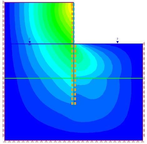
5 Question 1.3 Now model the problem by using RocScience RS2 software. Complete the excavation in 3 sets of 2m excavation stages. Assume a socket depth of 9m. Draw the axial force, shear and moment diagrams for each excavation stages. Similarly draw horizontal & vertical displacement profiles. For this question, the cantilever pile wall is modelled in RS2 software using the following properties; Model geometry and the generated mesh for the question;

 is used.")
6 Moreover, The model is staged in 4 stages. First one being without any excavation and the following three stages being 2m excavation stages. The cantilever pile wall model used is an elastic standard beam that has no reinforcement in. This has no non-neglectable effect over the force/shear/moment diagrams, but it should effect the horizontal & vertical displacement profiles. For the definition of soil material, effective Poisson ratio (v ) is used. Moment/Shear/Axial Force diagrams and Vertical & Horizontal Displacement profiles for each stage is as follows; Stage 1 - Horizontal Displacement - Maximum Value m - Minimum Value m - Vertical Displacement - Maximum Value 0m - Minimum Value m


7 Stage 2 - Horizontal Displacement - Maximum Value m - Minimum Value m - Vertical Displacement - Maximum Value m - Minimum Value m


8 Stage 3 - Horizontal Displacement - Maximum Value m - Minimum Value m - Vertical Displacement - Maximum Value m - Minimum Value m


9 Stage 4 - Horizontal Displacement - Maximum Value m - Minimum Value 0m - Vertical Displacement - Maximum Value


10 The following questions will be analysed using the maximum values obtained from all four stages of this analysis.

11 Question 1.4 Check if 16 Φ20 reinforcement with concrete cover of 7.5 cm is suitable to resist the estimated maximum moments. For the analysis of the reinforced concrete cantilever pile wall, the pile wall is modelled as a column for this question. In the analysis, methods described in A.Topçu s textbook Reinforced Concrete [1] and U.Ersoy s charts[2] for cylindrical columns are used. Estimated concrete & reinforcement specifications are; Concrete: C30/37 fcd=20mpa Reinforcement: B420C fyd=365.22mpa The chart used for this analysis, Figure 3 - Chart 8-53[2]

12 Design Moment Md = knm Design Axial Force = 64 kn Area of Concrete = mm 4 2 d h Chart 8-53 is selected. 80 Nd Af c cd M d A h f c cd m 0.08 Read from the Chart 8-53 f yd f 20 cd Ast mm Required reinforcement area Ast mm mm Checked Checked Reinforcement is suitable to resist the estimated maximum moments.
13 Question 1.5 Check if Φ16/ 20 cm spiral reinforcement fulfills the shear demand. For the analysis of the spiral reinforcement a beam model is used in order to check the fulfilment of the shear demand. A.Topçu s textbook Reinforced Concrete [1] is used for this analysis also. Design Shear Force = kn Design Axial Force = kN Area of Concrete = mm 4 2 Max. Shear Force = Vmax 0.22 f A kN cd c Critical Shear Force = ( 0.3) Nd Vcr 0.65 fctd Ac (1 ) kN A c V V V Shear demand can single-handedly fulfilled by concrete cross-section d only. cr max If the shear demand can single-handedly fulfilled by concrete only, then it is safe to say that Φ16/ 20 cm spiral reinforcement would also fulfil the shear demand.

14 Question 1.6 After the completion of the design, a piezometer was installed at 13 m depth which recorded pore water pressure of 100 kpa. Discuss how this data may change your assessment. Normally, the expected pore water pressure at 13m depth is around 80 kpa. This could be seen in the figure below. If the pore pressure is 100kPa at that depth, this would indicate a 25% increase in pore pressure at that depth. This would approximately mean a 25% increase in the axial, shear forces and moments for the cantilever pile wall. According to the calculations in 1.5 and 1.4 structurally, pile wall would still fulfil those extra forces. That being said, with the increase in the pore water pressure, excavation behind the wall could be subjected to base heave but boiling or seepage into the excavation is not expected due to cohesive soil both under and around the excavation. References [1] A.Topçu, Reinforced Concrete [2] U. ERSOY, Taşıma Gücü El Kitabı. Ankara, [3] Cetin, K. O. (2016), Deep Excavations & Retaining Stuctures Lecture 6
DESIGN OF AXIALLY LOADED STEPPED FOOTING DATA :- SBC of soil =200 KN /m 2 Concrete Mix =M20 Steel Grade = Fe 415 Clear cover of bottom slab =50 mm
 STEPPED FOOTING The construction of sloped footing is sometimes difficult and when the slope of the top face of footing is more, say more than 1 vertically to 3 horizontally, it may be difficult to finish
m v = 1.04 x 10⁻⁴ m 2 /kn, C v = 1.29 x 10⁻² cm 2 /min
 2.10 Problems Example 2.1: Design of Shallow Foundation in Saturated Clay Design a square footing to support a column load of 667 kn. The base of the footing will be located 1 m below the ground level
Formation level = m. Foundation level = m. Height of the wall above the Ground Level = 7.42 m
 DESIGN OF RETAINING WALL INTRODUCTION: This wall is designed for active earth pressure and live load surcharge pressure The loads for the purpose of design are calculated per meter length of wall. BASIC
Reinforced Soil Retaining Walls-Design and Construction
 Lecture 32 Reinforced Soil Retaining Walls-Design and Construction Prof. G L Sivakumar Babu Department of Civil Engineering Indian Institute of Science Bangalore 560012 Example calculation An 8 m high
UNIT-I SOIL EXPLORATION
 SIDDHARTH GROUP OF INSTITUTIONS :: PUTTUR Siddharth Nagar, Narayanavanam Road 517583 QUESTION BANK (DESCRIPTIVE) Subject with Code : Geotechnical Engineering - II (16CE127) Year & Sem: III-B.Tech & II-Sem
computed using Equation 3-18 by setting the 2nd term equal to 0 and K A equal to K o and using the pressure distribution as shown in Figure 3-23.
 computed using Equation 3-18 by setting the 2nd term equal to 0 and K A equal to K o and using the pressure distribution as shown in Figure 3-23. (2) For the resisting side, passive pressure theory indicates
This document downloaded from vulcanhammer.net vulcanhammer.info Chet Aero Marine
 This document downloaded from vulcanhammer.net vulcanhammer.info Chet Aero Marine Don t forget to visit our companion site http://www.vulcanhammer.org Use subject to the terms and conditions of the respective
INSTITUTE OF AERONAUTICAL ENGINEERING (Autonomous) Dundigal, Hyderabad
 Dundigal, Hyderabad") INSTITUTE OF AERONAUTICAL ENGINEERING (Autonomous) Dundigal, Hyderabad - 500 043 CIVIL ENGINEERING Tutorial Question Bank Name : FOUNDATION ENGINEERING Code : A60126 Class : III B. Tech II Semester Branch
INSTITUTE OF AERONAUTICAL ENGINEERING (Autonomous) Dundigal, Hyderabad - 500 043 CIVIL ENGINEERING Tutorial Question Bank Name : FOUNDATION ENGINEERING Code : A60126 Class : III B. Tech II Semester Branch
Effective stress. Chapter Total vertical stress at 5 m depth: kpa. Pore water pressure: kpa. Therefore, effective vertical stress: kpa
 Chapter 3 Effective stress 3.1 Figure Q3.1 Total vertical stress at 5 m depth: Pore water pressure: Therefore, effective vertical stress: Alternative method: Buoyant unit weight: Effective vertical stress:
Department of Civil & Geological Engineering GEOE Engineering Geology
 Department of Civil & Geological Engineering GEOE 218.3 Engineering Geology Assignment #3, Head, Pore Pressure & Effective Stress Due 08 Oct, 2010 NOTE: Numbered subscripts indicate depth, in metres, below
Tension Cracks. Topics Covered. Tension crack boundaries Tension crack depth Query slice data Thrust line Sensitivity analysis.
 Tension Cracks 16-1 Tension Cracks In slope stability analyses with cohesive soils, tension forces may be observed in the upper part of the slope. In general, soils cannot support tension so the results
INSTITUTE OF AERONAUTICAL ENGINEERING (Autonomous) Dundigal, Hyderabad CIVIL ENGINEERING TUTORIAL QUESTION BANK
 Dundigal, Hyderabad CIVIL ENGINEERING TUTORIAL QUESTION BANK") INSTITUTE OF AERONAUTICAL ENGINEERING (Autonomous) Dundigal, Hyderabad - 00 04 CIVIL ENGINEERING TUTORIAL QUESTION BANK Course Name Course Code Regulation Course Structure Course Coordinator Course Faculty
INSTITUTE OF AERONAUTICAL ENGINEERING (Autonomous) Dundigal, Hyderabad - 00 04 CIVIL ENGINEERING TUTORIAL QUESTION BANK Course Name Course Code Regulation Course Structure Course Coordinator Course Faculty
SOLUTIONS TO TUTORIAL EXAMPLES CHAPTER 13
 SOLUTIONS TO TUTORIAL EXAMPLES CHAPTER 13 Note: The reader may find these solutions easier to follow if he/she marks the forces on a diagram of the frame as he/she proceeds through the calculations. Question
APPENDIX G SCA BASIN CALCULATIONS
 ONONDAGA LAKE SEDIMENT MANAGEMENT FINAL DESIGN APPENDIX G SCA BASIN CALCULATIONS p:\honeywell -syr\444853 - lake detail design\09 reports\9.22 sediment management final design\110930 submittal\110906 onon
Lateral Load Analysis Considering Soil-Structure Interaction. ANDREW DAUMUELLER, PE, Ph.D.
 Lateral Load Analysis Considering Soil-Structure Interaction ANDREW DAUMUELLER, PE, Ph.D. Overview Introduction Methods commonly used to account for soil-structure interaction for static loads Depth to
REPORT GEO-TECHNICAL INVESTIGATION FOR THE PROPOSED BLOCK-7 SUB-STATION SY NO-225, NEAR RAYACHERLU VILLAGE
 REPORT ON GEO-TECHNICAL INVESTIGATION FOR THE PROPOSED BLOCK-7 SUB-STATION SY NO-225, NEAR RAYACHERLU VILLAGE CLIENT: KARNATAKA SOLAR POWER DEVELOPMENT CORPORATION BANGALORE 0 GEO-TECHNICAL INVESTIGATION
REPORT GEO-TECHNICAL INVESTIGATION FOR THE PROPOSED BLOCK-1 SUB-STATION SY NO-44, NEAR KYATAGANACHERLU VILLAGE
 REPORT ON GEO-TECHNICAL INVESTIGATION FOR THE PROPOSED BLOCK-1 SUB-STATION SY NO-44, NEAR KYATAGANACHERLU VILLAGE CLIENT: KARNATAKA SOLAR POWER DEVELOPMENT CORPORATION BANGALORE 0 GEO-TECHNICAL INVESTIGATION
Tutorial 5 Relative equilibrium
 Tutorial 5 Relative equilibrium 1. n open rectangular tank 3m long and 2m wide is filled with water to a depth of 1.5m. Find the slope of the water surface when the tank moves with an acceleration of 5m/s
The tensile capacity of suction caissons in sand under rapid loading
 Frontiers in Offshore Geotechnics: ISFOG 25 Gourvenec & Cassidy (eds) 25 Taylor & Francis Group, London, ISBN 415 3963 X The tensile capacity of suction caissons in sand under rapid loading Guy T. Houlsby,
Displacement-based calculation method on soil-pile interaction of PHC pipe-piles
 Seattle, WA Displacement-based calculation method on soil-pile interaction of PHC pipe-piles Dr. Huang Fuyun Fuzhou University 31 st May, 217 Outline Background ing introduction ing results Simple calculation
Cubzac-les-Ponts Experimental Embankments on Soft Clay
 Cubzac-les-Ponts Experimental Embankments on Soft Clay GEO-SLOPE International Ltd. www.geo-slope.com 1, 7 - th Ave SW, Calgary, AB, Canada TP T Main: +1 3 9 Fax: +1 3 39 Introduction In the 197 s, a series
Prof. B V S Viswanadham, Department of Civil Engineering, IIT Bombay
 43 Module 3: Lecture - 5 on Compressibility and Consolidation Contents Stresses in soil from surface loads; Terzaghi s 1-D consolidation theory; Application in different boundary conditions; Ramp loading;
Analysis of dilatometer test in calibration chamber
 Analysis of dilatometer test in calibration chamber Lech Bałachowski Gdańsk University of Technology, Poland Keywords: calibration chamber, DMT, quartz sand, FEM ABSTRACT: Because DMT in calibration test
Theory of a vertically loaded Suction Pile in CLAY
 11 Theory of a vertically loaded Suction Pile in CLAY Mainly based on the et Norske Veritas NV-RP-E303 1. Convention Water COG h L Soil COG t Figure 1 Suction Pile Figure 2 Suction pile with main parameters
Lab 7 Rotational Equilibrium - Torques
 Lab 7 Rotational Equilibrium - Torques Objective: < To test the hypothesis that a body in rotational equilibrium is subject to a net zero torque and to determine the typical tension force that the biceps
Irrigation &Hydraulics Department lb / ft to kg/lit.
 CAIRO UNIVERSITY FLUID MECHANICS Faculty of Engineering nd Year CIVIL ENG. Irrigation &Hydraulics Department 010-011 1. FLUID PROPERTIES 1. Identify the dimensions and units for the following engineering
CENGRS GEOTECHNICA PVT. LTD. Job No Sheet No. 1
 CENGRS GEOTECHNICA PVT. LTD. Job No. 214030 Sheet No. 1 INTERIM REPORT ON GEOTECHNICAL INVESTIGATION FOR PROPOSED 66 KV GRID PLOT AT G-7, DWARKA, NEW DELHI. 1.0 INTRODUCTION 1.1 Project Description M/s.
CHAPTER IV FINITE ELEMENT ANALYSIS OF THE KNEE JOINT WITHOUT A MEDICAL IMPLANT
 39 CHAPTER IV FINITE ELEMENT ANALYSIS OF THE KNEE JOINT WITHOUT A MEDICAL IMPLANT 4.1 Modeling in Biomechanics The human body, apart of all its other functions is a mechanical mechanism and a structure,
Pore-Air Entrapment during Infiltration
 Pore-Air Entrapment during Infiltration GEO-SLOPE International Ltd. www.geo-slope.com 1200, 700-6th Ave SW, Calgary, AB, Canada T2P 0T8 Main: +1 403 269 2002 Fax: +1 888 463 2239 Introduction Infiltration
Pressure Measurement
 Pressure Measurement Absolute and Gage Pressure P abs = P gage + P atm where P abs = Absolute pressure P abs = Gage pressure P abs = atmospheric pressure A perfect vacuum is the lowest possible pressure.
Influence of Settlement on Bearing Capacity Analysis of Shallow Foundations on Sandy Clays in the Niger Delta, Nigeria
 Available online at www.scholarsresearchlibrary.com European Journal of Applied Engineering and Scientific Research, 201, 2 (4):20-27 (http://scholarsresearchlibrary.com/archive.html) ISSN: 22 0041 Influence
Pushover analysis with ZSOIL taking soil into account. Stéphane Commend GeoMod Ing. SA, Lausanne
 Pushover analysis with ZSOIL taking soil into account Stéphane Commend GeoMod Ing. SA, Lausanne scommend@geomod.ch Contents Motivation Why pushover? Why take soil into account? Brief recall of pushover
Adaptive Pushover Analysis of Irregular RC Moment Resisting Frames
 Kalpa Publications in Civil Engineering Volume 1, 2017, Pages 132 136 ICRISET2017. International Conference on Research and Innovations in Science, Engineering &Technology. Selected papers in Civil Engineering
Pros and Cons of the Analysis of Slope Stability by Various Methods of Slices or Columns
 Pros and Cons of the Analysis of Slope Stability by Various Methods of Slices or Columns by Robert Pyke Ph.D., G.E. Partially Completed Draft April 22, 2017 General Background The history of slope stability
DEPARTMENT OF CIVIL ENGINEERING, IIT BOMBAY CE306 STRUCTURAL MECHANICS III
 Tutorial sheet- EPRTMENT OF V ENGNEERNG, T OMY E06 STRUTUR MEHNS nstructor: r. R. S. Jangid. erive the flexibility matrix for the structures in Figure (a) to (e) with respect to the coshown ordinates.
Introduction of world construction methods and trends. Franz-Werner Gerressen, Head of Method Development, Tokyo,
 Introduction of world construction methods and trends Franz-Werner Gerressen, Head of Method Development, Tokyo, 2017-11-29 1 Introduction of world construction methods and trends Outline Single Pass Piling
Exam Question 9: Hydrostatics. March 6, Applied Mathematics: Lecture 8. Brendan Williamson. Introduction. Density, Weight and Volume
 Exam Question 9: Hydrostatics March 6, 2017 This lecture is on hydrostatics, which is question 9 of the exam paper. Most of the situations we will study will relate to objects partly or fully submerged
APPLICATION OF PUSHOVER ANALYSIS ON EARTHQUAKE RESPONSE PREDICATION OF COMPLEX LARGE-SPAN STEEL STRUCTURES
 APPLICATION OF PUSHOVER ANALYSIS ON EARTHQUAKE RESPONSE PREDICATION OF COMPLEX LARGE-SPAN STEEL STRUCTURES J.R. Qian 1 W.J. Zhang 2 and X.D. Ji 3 1 Professor, 3 Postgraduate Student, Key Laboratory for
Infiltration and Air Pressure Build-up
 1 Introduction Infiltration and Air Pressure Build-up This air flow example illustrates how the build-up of air pressure in advance of a wetting front can inhibit water movement. The example is based on
SOIL ANCHORS ETSAB/UPC J.Llorens - ETSAB/UPC PASSIVE ANCHORS - ANTECEDENTS
 SOIL ANCHORS ignasi.llorens@upc.edu ETSAB/UPC - 2013 PASSIVE ANCHORS - ANTECEDENTS Antecedents of passive anchors can be found in Nature. Roots feed plants and provide uplift resistance against the wind
Bearing Capacity and Settlement Response of PMS Tanks on Cohesionless Soil Lithology in Lekki, Lagos of Nigeria
 Available online at www.scholarsresearchlibrary.com European Journal of Applied Engineering and Scientific Research,, ():- (http://scholarsresearchlibrary.com/archive.html) ISSN: 8 Bearing Capacity and
Assistant Lecturer Anees Kadhum AL Saadi
 Pressure Variation with Depth Pressure in a static fluid does not change in the horizontal direction as the horizontal forces balance each other out. However, pressure in a static fluid does change with
Erratum to: Effect of seabed slope on the pile behaviour of a fixed offshore platform under lateral forces
 J. Ocean Eng. Mar. Energy (215) 1:223 236 DOI 1.17/s4722-15-15-5 ERRATUM Erratum to: Effect of seabed slope on the pile behaviour of a fixed offshore platform under lateral forces K. Muthukkumaran K. S.
Module 7 Lecture 1. Swelling and Collapse Behavior
 Swelling and Collapse Behavior Module 7 Lecture 1 Collapse and swelling phenomena occur in unsaturated soils during the saturation process. The compacted unsaturated soils, on the dry of optimum, have
Engineering Practice on Ice Propeller Strength Assessment Based on IACS Polar Ice Rule URI3
 10th International Symposium on Practical Design of Ships and Other Floating Structures Houston, Texas, United States of America 2007 American Bureau of Shipping Engineering Practice on Ice Propeller Strength
Desaturating sand deposit by air injection for reducing liquefaction potential
 Desaturating sand deposit by air injection for reducing liquefaction potential M. Ishihara, M. Okamura & T. Oshita Public Works Research Institute, Tsukuba City, Japan. ABSTRACT: It has been known that
Submerged Slope with Excess Pore- Water Pressure
 Submerged Slope with Excess Pore- Water Pressure GEO-SLOPE International Ltd. www.geo-slope.com 1400, 633-6th Ave SW, Calgary, AB, Canada T2P 2Y Main: +1 403 269 02 Fax: +1 403 266 481 Introduction Analyzing
Equipment Productivity
 Arab Academy for Science, Technology & Maritime Transport College of Engineering & Technology Construction & Building Engineering CB 524 Methods and Equipment for Construction 2 Equipment Productivity
ESTIMATION OF LATERAL SPREAD OF A CAISSON TYPE QUAY CAUSED BY BACK FILL LIQUEFACTION
 ESTIMATION OF LATERAL SPREAD OF A CAISSON TYPE QUAY CAUSED BY BACK FILL LIQUEFACTION Kunio MIZUMOTO 1, Tetsuya TSURUMI 2, Hidekatsu NAKAJIMA 3 And Susumu OKADA 4 SUMMARY It is said on the lateral spread
Theory of multi-bench retaining for large area foundation pit and its engineering application
 DOI:10.16285/j.rsm.2014.s2.085 35 2 Vol.35 Supp.2 2014 10 Rock and Soil Mechanics Oct. 2014 1000 7598 (2014) 2 0290 09 300072 TU 470 A Theory of multi-bench retaining for large area foundation pit and
Fehmarnbelt Fixed Link. Geotechnical Large Scale Testing
 Fehmarnbelt Fixed Link. Geotechnical Large Scale Testing A. Reto Schreier GEO, Denmark, rsc@geo.dk B. Anders Tovsig Schaarup Andersen Per Aarsleff A/S, Denmark, ata@aarsleff.com C. Nataša Katić + Peter
Vertical Uplift Capacity of a Group of Equally Spaced Helical Screw Anchors in Sand
 SECM/15/080 Vertical Uplift Capacity of a Group of Equally Spaced Helical Screw Anchors in Sand S. Mukherjee 1* and Dr. S. Mittal 2 1 Amity University, Noida, India 2 Indian Institute of Technology, Roorkee,
Deepwater Challenges Pipeline Installation Case
 Deepwater Challenges Pipeline Installation Case Seminar Nasional Oceano, ITS, 28 March 2011, Surabaya Gunawan Suwarno, 28 March 2011 DeepLay Energy Services email : marketing@deep-lay.com 1 Deepwater Development
Truss Analysis Method of Sections Steven Vukazich San Jose State University
 Truss Analysis Method of Sections Steven Vukazich San ose State University General Procedure for the Analysis of Simple Trusses using the Method of Sections 1. Draw a ree Body Diagram (BD) of the entire
Conventional Ship Testing
 Conventional Ship Testing Experimental Methods in Marine Hydrodynamics Lecture in week 34 Chapter 6 in the lecture notes 1 Conventional Ship Testing - Topics: Resistance tests Propeller open water tests
COMPFIRE CCFT-FP_550_55_ September 2010 Fin Plate Connection to Circular Concrete-Filled Tube Test Result
 Reaction Frame Macalloy Bars Camera 3 Support Beam α Oven Bar Camera 2 Link Bar Camera 1 Tested Connection Jack Bar Electrical Furnace Reaction Frame Load Jack v2_5 April 2011 1 Oven Bar Link Bar View
Item 404 Driving Piling
 Item Driving Piling 1. DESCRIPTION Drive piling. 2. EQUIPMENT 2.1. Driving Equipment. Use power hammers for driving piling with specified bearing resistance. Use power hammers that comply with Table 1.
Mechanical Stabilisation for Permanent Roads
 Mechanical Stabilisation for Permanent Roads Tim Oliver VP Global Applications Technology Tensar International toliver@tensar.co.uk Effect of geogrid on particle movement SmartRock Effect of geogrid on
STABILITY OF MULTIHULLS Author: Jean Sans
 STABILITY OF MULTIHULLS Author: Jean Sans (Translation of a paper dated 10/05/2006 by Simon Forbes) Introduction: The capsize of Multihulls requires a more exhaustive analysis than monohulls, even those
A STUDY ON LIQUEFIED GROUND DISRUPTION EFFECTS ON LIQUID STORAGE TANK BEHAVIOR
 143 A STUDY ON LIQUEFIED GROUND DISRUPTION EFFECTS ON LIQUID STORAGE EHAVIOR Mutsuhiro YOSHIZAWA 1, Sadatomo ONIMARU 2, Akihiko UCHIDA 3 And Munenori HATANAKA 4 SUMMARY Three liquid storage tanks located
Level 3 Cambridge Technical in Engineering 05822/05823/05824/05825/05873 Unit 3: Principles of mechanical engineering
 Level 3 Cambridge Technical in Engineering 05822/05823/05824/05825/05873 Unit 3: Principles of mechanical engineering Monday 16 January 2017 Afternoon Time allowed: 1 hour 30 minutes You must have: the
3. Types of foundation
 Foundation Engineering CE 48. Types of foundation & foundation materials Contents Introduction Shallow Foundations Deep Foundations Introduction Why different types of? General types of Introduction Why
V-H-M Yield Surface describing Soil Structure Interaction of Sub-sea Structures and Wind Turbines on Caisson Foundations in Soft Clays
 NGM 2016 Reykjavik Proceedings of the 17 th Nordic Geotechnical Meeting Challenges in Nordic Geotechnic 25 th 28 th of May V-H-M Yield Surface describing Soil Structure Interaction of Sub-sea Structures
RELIABILITY ASSESSMENT, STATIC AND DYNAMIC RESPONSE OF TRANSMISSION LINE TOWER: A COMPARATIVE STUDY
 RELIABILITY ASSESSMENT, STATIC AND DYNAMIC RESPONSE OF TRANSMISSION LINE TOWER: A COMPARATIVE STUDY Yusuf Mansur Hashim M. Tech (Structural Engineering) Student, Sharda University, Greater Noida, (India)
ABSTRACT. The design of a temporary slope and excavation retaining wall system often is carried out
 ABSTRACT LEE, JUNGMOK. Analysis and Design of Temporary Slopes and Excavation Support Systems in Unsaturated Piedmont Residual Soils. (Under the direction of Dr. Roy H. Borden and Dr. Mohammed A. Gabr).
FC-CIV HIDRCANA: Channel Hydraulics Flow Mechanics Review Fluid Statics
 FC-CIV HIDRCANA: Channel Hydraulics Flow Mechanics Review Fluid Statics Civil Engineering Program, San Ignacio de Loyola University Objective Calculate the forces exerted by a fluid at rest on plane or
σ = force / surface area force act upon In the image above, the surface area would be (Face height) * (Face width).
 * (Face width).") Aortic Root Inflation Introduction You have already learned about the mechanical properties of materials in the cantilever beam experiment. In that experiment you used bending forces to determine the Young
Aortic Root Inflation Introduction You have already learned about the mechanical properties of materials in the cantilever beam experiment. In that experiment you used bending forces to determine the Young
3. Moments and Pressure
 Leaving Cert Physics Long Questions 2017-2002 3. Moments and Pressure Remember to photocopy 4 pages onto 1 sheet by going A3 A4 and using back to back on the photocopier Contents Moments: ordinary level
THE EFFECT OF EMBEDMENT DEPTH ON BEARING CAPACITY OF STRIP FOOTING IN COHESIVE FRICTIONAL MEDIUM
 Proceedings of the 4 th International Conference on Civil Engineering for Sustainable Development (ICCESD 2018), 9~11 February 2018, KUET, Khulna, Bangladesh (ISBN-978-984-34-3502-6) THE EFFECT OF EMBEDMENT
Saturated-Unsaturated Consolidation
 Introduction Saturated-Unsaturated Consolidation This example looks at the volume change behavior of a saturated-unsaturated column under loading, wetting and drying conditions. Feature Highlights GeoStudio
Pressuremeters in Geotechnical Design
 Pressuremeters in Geotechnical Design B.G. CLARKE Department of Civil Engineering University of Newcastle upon Tyne BLACK1E ACADEMIC & PROFESSIONAL An Imprint of Chapman & Hall London Glasgow Weinheim
(Refer Slide Time: 1:22)
") Foundation for Offshore Structures Professor S. Nallayarasu Department of Ocean Engineering Indian Institute of Technology Madras Module 1 Lecture 17 Pile Installation 2 Anyway we will continue with pile
Foundation for Offshore Structures Professor S. Nallayarasu Department of Ocean Engineering Indian Institute of Technology Madras Module 1 Lecture 17 Pile Installation 2 Anyway we will continue with pile
Typical factors of safety for bearing capacity calculation in different situations
 Typical factors of safety for bearing capacity calculation in different situations Density of soil: In geotechnical engineering, one deals with several densities such as dry density, bulk density, saturated
Applying Hooke s Law to Multiple Bungee Cords. Introduction
 Applying Hooke s Law to Multiple Bungee Cords Introduction Hooke s Law declares that the force exerted on a spring is proportional to the amount of stretch or compression on the spring, is always directed
. In an elevator accelerating upward (A) both the elevator accelerating upward (B) the first is equations are valid
 both the elevator accelerating upward (B) the first is equations are valid") IIT JEE Achiever 2014 Ist Year Physics-2: Worksheet-1 Date: 2014-06-26 Hydrostatics 1. A liquid can easily change its shape but a solid cannot because (A) the density of a liquid is smaller than that of
IIT JEE Achiever 2014 Ist Year Physics-2: Worksheet-1 Date: 2014-06-26 Hydrostatics 1. A liquid can easily change its shape but a solid cannot because (A) the density of a liquid is smaller than that of
THE USE OF SPIN FIN PILES IN MASSACHUSETTS
 THE USE OF SPIN FIN PILES IN MASSACHUSETTS Les R. Chernauskas, P.E., Geosciences Testing and Research, Inc., North Chelmsford, MA Leo J. Hart, Geosciences Testing and Research, Inc., North Chelmsford,
A comprehensive method for the structural design and verification of the INNWIND 10MW tri-spar floater
 NATIONAL TECHNICAL UNIVERSITY of ATHENS (NTUA) A comprehensive method for the structural design and verification of the INNWIND 10MW tri-spar floater DI Manolas, CG Karvelas, IA Kapogiannis, VA Riziotis,
3 1 PRESSURE. This is illustrated in Fig. 3 3.
 P = 3 psi 66 FLUID MECHANICS 150 pounds A feet = 50 in P = 6 psi P = s W 150 lbf n = = 50 in = 3 psi A feet FIGURE 3 1 The normal stress (or pressure ) on the feet of a chubby person is much greater than
Edit this text for your title
 Edit this text for your title MEK 4450 Marine Operations 1-3 Edit this text for your sub-title Presenter name, location, date etc. Kværner ASA / DNV, Fall 2014 Installation of flexibles and cables Typical
The Usage of Propeller Tunnels For Higher Efficiency and Lower Vibration. M. Burak Şamşul
 The Usage of Propeller Tunnels For Higher Efficiency and Lower Vibration M. Burak Şamşul ITU AYOC 2014 - Milper Pervane Teknolojileri Company Profile MILPER is established in 2011 as a Research and Development
LYSAGHT W-DEK. Design and Construction Manual. Structural steel decking system
 LYSAGHT W-DEK Structural steel decking system Design and Construction Manual ptimised to bring greater efficiency, speed of construction and economy. Exceptional spanning characteristics (up to 4.1m) reduces
Effect of Depth of Periphery Beams on Behavior of Grid Beams on Grid Floor
 International Journal of Current Engineering and Technology E-ISSN 2277 4106, P-ISSN 2347 5161 2015 INPRESSCO, All Rights Reserved Available at http://inpressco.com/category/ijcet Research Article Effect
Quantitative Risk of Linear Infrastructure on Permafrost Heather Brooks, PE. Arquluk Committee Meeting November 2015
 Slide 1 Quantitative Risk of Linear Infrastructure on Permafrost Heather Brooks, PE Arquluk Committee Meeting November 2015 Welcome to the meeting of the committee for Arquluk s Quantitative Risk of Linear
Application of pushover analysis in estimating seismic demands for large-span spatial structure
 28 September 2 October 2009, Universidad Politecnica de Valencia, Spain Alberto DOMINGO and Carlos LAZARO (eds.) Application of pushover analysis in estimating seismic demands for large-span spatial structure
SHEAR PERFORMANCE OF RC FOOTING BEAMS BY CAP-TIE SYSTEM USING WELDED STIRRUPS
 The 7th International Conference of Asian Concrete Federation SUSTAINABLE CONCRETE FOR NOW AND THE FUTURE 3 Oct 2 Nov, 216, Hanoi, Vietnam www.acf216.vn SHEAR PERFORMANCE OF RC FOOTING BEAMS BY CAP-TIE
using Strength Ratios
 Shear Strength of Liquefied Soil using Strength Ratios Prof. Scott M. Olson, PhD, PE 86 th Annual Meeting Transportation Research Board January 22, 2007 Liquefaction Problems Photos from eeri.org Undrained
Impact Test Equipment Ltd & User Guide. User Guide
 SL Impact Test Equipment Ltd www.impact-test.co.uk & www.impact-test.com User Guide User Guide Impact Test Equipment Ltd. Building 21 Stevenston Ind. Est. Stevenston Ayrshire KA20 3LR T: 01294 602626 F:
Slope Stability Analysis Of Class I Landfills With Co Disposal Of Bios
 University of Central Florida Electronic Theses and Dissertations Masters Thesis (Open Access) Slope Stability Analysis Of Class I Landfills With Co Disposal Of Bios 2004 Mrutyunjay Vajirkar University
HCMTCB MATERIALS SAMPLING & TESTING PERFORMANCE CHECKLIST
 HCMTCB MATERIALS SAMPLING & TESTING PERFORMANCE CHECKLIST Release Date: January 7, 2014 Sampling Coarse Aggregate PERFORMANCE CHECKLIST AASHTO T-2 Sampling of Aggregates Sampling From A Stockpile 1 When
ME311 Machine Design
 E311 achine Design Lecture 6: Fluctuating Fatigue and the Goodman Diagram; Impact W Dornfeld 19Oct17 Fairfield University chool of Engineering Fluctuating Fatigue o far we have discussed loading that ernately
[Barve, 4(7): July, 2015] ISSN: (I2OR), Publication Impact Factor: 3.785
![[Barve, 4(7): July, 2015] ISSN: (I2OR), Publication Impact Factor: 3.785](/thumbs/96/128298826.jpg "[Barve, 4(7): July, 2015] ISSN: (I2OR), Publication Impact Factor: 3.785") IJESRT INTERNATIONAL JOURNAL OF ENGINEERING SCIENCES & RESEARCH TECHNOLOGY PARAMETRIC STUDY TO UNDERSTAND THE SEISMIC BEHAVIOUR OF INTZE TANK SUPPORTED ON SHAFT Prasad S. Barve *, Ruchi P. Barve * Civil
IJESRT INTERNATIONAL JOURNAL OF ENGINEERING SCIENCES & RESEARCH TECHNOLOGY PARAMETRIC STUDY TO UNDERSTAND THE SEISMIC BEHAVIOUR OF INTZE TANK SUPPORTED ON SHAFT Prasad S. Barve *, Ruchi P. Barve * Civil
PhysicsAndMathsTutor.com
 PhysicsAndMathsTutor.com 6. Figure 2 3 m 0.5 m A D B June 2005 C 30 A uniform pole AB, of mass 30 kg and length 3 m, is smoothly hinged to a vertical wall at one end A. The pole is held in equilibrium
SPECIAL FOOTINGS AND BEAMS ON ELASTIC FOUNDATIONS
 CHAPTER 9 SPECIAL FOOTINGS AND BEAMS ON ELASTIC FOUNDATIONS 9-1 INTRODUCTION This chapter will take up the design of several of the more complicated foundation members such as those required to support
3. A fluid is forced through a pipe of changing cross section as shown. In which section would the pressure of the fluid be a minimum?
 AP Physics Multiple Choice Practice Fluid Mechanics 1. A cork has weight mg and density 5% of water s density. A string is tied around the cork and attached to the bottom of a water-filled container. The
The Adequacy of Pushover Analysis to Evaluate Vulnerability of Masonry Infilled Steel Frames Subjected to Bi-Directional Earthquake Loading
 The Adequacy of Pushover Analysis to Evaluate Vulnerability of Masonry Infilled Steel Frames Subjected to Bi-Directional Earthquake Loading B.Beheshti Aval & M. Mohammadzadeh K.N.Toosi University of Technology,
Semi-Submersible Offshore Platform Simulation Using ANSA & META
 Semi-Submersible Offshore Platform Simulation Using ANSA & META Offshore platforms are large structures designed to withstand extreme weather conditions and have a lifespan of at least 40 years. Million
Cabling in Multiple Fall Ropes of Lifting Systems for Deep Water
 OIPEEC Conference Stuttgart March 015 C. R. Chaplin The University of Reading / Reading Rope Consultants LLP, UK Cabling in Multiple Fall Ropes of Lifting Systems for Deep Water Summary Cabling is the
TYPES OF FOUNDATION. Superstructure. Substructure. Foundation
 TYPES OF FOUNDATION Introduction: The lowest artificially built part of a structure which transmits the load of the structure to the soil lying underneath is called foundation. The supporting part of a
Pressure Plate Drying and Wetting
 1 Introduction Pressure Plate Drying and Wetting This air flow example illustrates how the process of axis translation, which is used in pressure plates to measure the water content function, can be modeled.
Session 1. Pushover Analysis of a Torsionally Eccentric Cellular Abutment. Date 11/03/ PM 4 PM Eastern Time
 Session 1 Pushover Analysis of a Torsionally Eccentric Cellular Abutment Date 11/03/2016 3 PM 4 PM Eastern Time Today s Presenter: Jon Emenheiser, PE Copyright Materials This presentation is protected