Commissioning Water Systems
|
|
|
- Anabel Scott
- 5 years ago
- Views:
Transcription


1 A BSRIA Guide Commissioning Water Systems By Chris Parsloe BG 2/2010
2
3 Acknowledgements The first edition of the publication BSRIA Application Guide, AG 2/89: Commissioning of water systems in buildings was produced as part of a research project in 1989 under the sponsorship of the Department of the Environment, Construction Directorate, and under the direction of an industry steering group. This new fully revised edition has been compiled with the help of a joint BSRIA CIBSE industry steering group under the chairmanship of Bryan Franklin, and designed and produced by Ruth Radburn. The steering group members were: AECOM Arup Ashford Environmental Services Banyards Barfield Belimo Burgess Group Commtech Crane Crown House Commissioning Specialists Association Danfoss End Systems Frese Raxcrest SAV SES Siemens Building Technologies Sutton Wates Mike Campbell Terry Dix Roger Carlin Nick Till Peter Barrett Luke Collier George Moss Nick Ward Andy Lucas Malcolm Moorby John Coppin Paul Wightman Brian Townsend Matthew Dunk Terry Dodge Lars Fabricius Chris Driscoll Gerry McGilley Bill McCluskey Lee Hansard BSRIA acknowledges the very significant contribution made by all the steering group members, but the responsibility for the document remains with BSRIA. We would also like to thank our author, Chris Parsloe, the team at CIBSE, Hywel Davies and Claire Ruston, and all those who contributed photographs for the Guide. This publication has been printed on Nine Lives Silk recycled paper, which is manufactured from 100% recycled fibre. All rights reserved. No part of this publication may be reproduced, stored in a retrieval system, or transmitted in any form or by any means electronic or mechanical including photocopying, recording or otherwise without prior written permission of the publisher. BSRIA BG 2/2009 June 2010 ISBN Printed by ImageData Ltd COMMISSIONING WATER SYSTEMS 1
4 Preface Photo of Bryan Franklin Bryan Franklin. To be written.. By Brian Franklin May COMMISSIONING WATER SYSTEMS
5 Contents Definitions 6 Abbreviations 7 List of symbols 8 1 Introduction Building Regulations Part L Guide content 9 2 Design for commissionability Commissioning specification Pipe system commissionability Pipe system layout Pipe sizing Pump sizing Commissioning devices Ultra low flow rates Pre-commission cleaning provisions Venting provisions De-aeration Provisions for measuring pressure Tolerances 15 3 Commissioning devices Regulating valves Flow measurement principles Flow measurement devices (FMDs) Improvised flow measurement Combined flow measurement and regulation device Constant flow regulator (CFR) Differential pressure control valves (DPCVs) Pressure independent control valves (PICVs) Guidelines for locating commissioning devices 34 4 The installation of commissionable systems Organisation and planning Installation issues affecting commissionaibility Housekeeping Workmanship Installation of commissioning devices Accessibility Draining provisions Venting Installation inspections Preparation for commissioning 40 COMMISSIONING WATER SYSTEMS 3
6 5 Site test instruments Rotational speed measurement Voltage and current measurement Flow measurement Pressure measurement BSRIA recommended test kit 45 6 Commissioning procedures Organisation and planning Setting to work Full system scan Regulation procedure Proportional balancing Flow setting Flow measurement accuracy 54 7 Example method statements Primary circuits Constant flow secondary circuits Variable flow secondary circuits Setting of total flow rate from the pump 66 8 Reporting and documentation Reporting Documentation Example pro formas 67 Appendices Appendix: A Flow rate tolerances 79 Appendix: B Proportional balancing procedure using measurements of pressure differential 80 4 COMMISSIONING WATER SYSTEMS
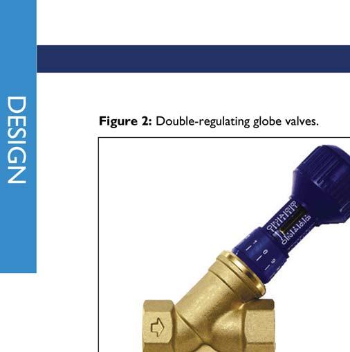
7 Tables Table 1: Recommended range of maximum water velocities. 12 Table 2: Suggested tolerances for flow regulation in heating systems 16 Table 3: Suggested tolerances for flow regulation in chilled water systems 17 Table 4: Commissioning device, terminologies and functions. 20 Table 5: Valve applications. 34 Table 6: Minimum straight lengths recommended upstream and downstream of flow measurement devices. 37 Table 7: BSRIA-recommended test kit. 46 Table 8: Tolerances for flow rate balancing in heating systems. 79 Table 9: Tolerances for flow rate balancing in heating systems. 79 Table 10: Regulation of terminal unit with interpretation of measurements. 80 Figures Figure 1: Heat transfer sensitivity for alternative heating and cooling coils. 18 Figure 2: Double-regulating globe valves. 22 Figure 3: Double-regulating butterfly. 22 Figure 4: Typical fixed-orifice fittings. 24 Figure 5: Flow rate measurements using fixed resistances. 26 Figure 6: Flow rate measurements in circuits with PICVs. 26 Figure 7: Flow rate measurements in circuits fed from manifolds. 27 Figure 8: Typical fixed-orifice double-regulating valves. 28 Figure 9: Typical variable orifice double regulating valves. 29 Figure 10: Cartridge type constant flow regulator. 30 Figure 11: Differential pressure control valves. 31 Figure 12: Pressure independent control valves. 33 Figure 13: 0-65 kpa. 44 Figure 14: Digital differential pressure and flow rate instrument. 45 Figure 15: The basis of proportional balancing. 50 Figure 16: Typical primary circuit arrangement. 55 Figure 17: A system feeding to fan coil units. 57 Figure 18: A constant flow system serving fan coil units. 59 Figure 19: A system feeding to radiators. 61 Figure 20: A variable flow system serving fan coil units. 63 Figure 21: A variable flow system serving fan coil units. 65 COMMISSIONING WATER SYSTEMS 5
8 Definitions Cavitation Chemical cleaning Commissionable system Commissionability Commissioning Commissioning Management Commissioning Management Organisation Commissioning specialist Commissioning specification Designer Design criteria Diversity Flushing Installation Pre-commissioning Pressure and leakage testing The localised vaporisation of a liquid caused when the absolute pressure of the liquid falls to a value approaching its vapour pressure. The removal of deposits such as scale, corrosion and biofilm from the internal surfaces of pipework by treatment with chemicals and in accordance with a formal procedure. A system designed, installed and prepared to specified requirements in such a manner as to enable commissioning to be carried out. The ability of a system to be commissioned satisfactorily. The advancement of an installation from the state of static completion to full working order to specified requirements. For pipework distribution systems it includes the setting to work of an installation and the regulation of flow rates. The planning, organisation, co-ordination and control of commissioning activities. The firm (or person) appointed to manage the commissioning process, being responsible for overall planning, supervision and witnessing of the results of the integrated commissioning of all installed building services systems. The firm (or person) appointed to carry out specified duties in connection with the commissioning of the engineering services. The document (or sub-section of the design specification) that prescribes the detailed objectives and requirements for commissioning. Note: the specification must refer to drawings, schedules and relevant parts of the codes, manuals, guides and other standards. The organisation (firm or persons) responsible for the design of the water services systems that are to be commissioned. Depending on the method of procurement this may be one or more organisation. In many instances the design intent of the water services systems may be set out by one organisation, with the final selection of some, or all, of the individual components (main plant, pumps, terminal equipment, control and regulating valves) by another organisation. Where this is the case the final system flow rates should be provided by the organisation that has selected the components, however this responsibility should be clearly set out in the contract documents. The specified performance of the system expressed as a numerical quantity together with allowable tolerances. The ratio between the anticipated peak heating or cooling load demand from a system, and the summated maximum heating or cooling capacities of the installed equipment. The washing out of an installation with water to a specified procedure in order to remove manufacturing and construction debris (as per BSRIA AG 1/2001 (14) ) A system placed in position as required by the design or specification. Specified systematic checking of a completed installation to confirm its state of readiness for commissioning. Note: Pre-commissioning is a post-installation completion activity. The measurement and recording of a specified pressure retention or loss within a system or system component. 6 COMMISSIONING WATER SYSTEMS
9 Proportional balancing Regulating Setting to work Static completion System Tolerance Water treatment specialist Witnessing authority The process of bringing the fluid flow rates throughout a distribution system into balance with one another, in their correct proportions and within tolerances specified by the designer. The process of adjusting the flow rates of a fluid in a distribution system to achieve the design flow rates within the tolerances specified by the designer. The process of setting a static system into operation. The state of a system when it is installed in accordance with the drawings and specification, i.e. clean and ready for setting to work. In the case of water systems this includes flushing, cleaning, pressure and leakage testing, filling and venting. A set of connected components for heating, cooling, ventilation or air conditioning consisting of plant, distribution ducting, piping and terminal units and arrangements to control their operation. The permissible range of variation from the specified design value. The firm (or person) appointed to carry out specified duties in connection with the flushing, chemical cleaning and water treatment of pipework systems. The firm or person that may sometimes be appointed to witness the results of commissioning, and to verify that results obtained comply with the requirements of the design criteria and commissioning specification. Abbreviations %DFR AHU CFR DRV DPCV FMD FODRV PICV TRV VODRV Percentage of design flow rate Air handling unit Constant flow regulator Double regulating valve Differential pressure control valve Flow measurement device Fixed orifice double regulating valve Pressure independent control valve Thermostatic radiator valve Variable orifice double regulating valve COMMISSIONING WATER SYSTEMS 7
10 8 COMMISSIONING WATER SYSTEMS List of symbols
11 1 Introduction This Guide explains how to commission water pipework distribution systems in buildings. The commissioning process mainly comprises the setting to work of the system pumps and the regulation (or proportional balancing) of system flow rates. The procedures set out in this guide, if undertaken, should achieve compliance with the requirements of CIBSE Code W Water Distribution Systems. In general, CIBSE Code W sets out the normal standards of good practice which are generally accepted within the building services industry. This guide explains how to carry out the commissioning procedure in a way that ensures these standards are achieved. The emphasis of this guide is on building heating and cooling systems although it may also be applied to other types of water distribution systems in buildings and industry. The guide is equally applicable to new-build and retrofit applications and is independent of the scale of the system. Compliance with the requirements of this guide does not confer immunity from relevant statutory and legal requirements. 1.1 BUILDING REGULATIONS PART L Part L1 of the Building Regulations in England and Wales requires that reasonable provision shall be made for the conservation of fuel and power in buildings by providing and commissioning energy efficient fixed building services with effective controls. The approved procedure by which compliance with Part L can be demonstrated is that set out in CIBSE Code M Commissioning Management, and, for pipework distribution systems, its sub-referenced document CIBSE Code W Water Distribution Systems. 1.2 GUIDE CONTENT The technical guidance is sub-divided into the following section headings: Section 2: Design for commissionability Section 3: Commissioning devices Section 4: Installation for commissionability Section 5: Site test instruments Section 6: Commissioning procedures Section 7: Example method statements Section 8: Documentation and reporting Sections 2 and 4 of the guide are deliberately aimed at system designers and installers. Unless commissioning is properly considered during both the design and installation stages of a project, it may not be possible to meet the requirements of CIBSE Code W. Section 3 provides a summary of the main commissioning devices available at the time of writing. Sections 5, 6, 7 and 8 are intended as guidance for commissioning specialists employed to undertake commissioning activities. COMMISSIONING WATER SYSTEMS 9
12 2 Design for commissionability Designers and project managers should address their attention to commissioning and the effective management of the process as soon as possible after embarking on a scheme design stage. Guidance on the management of the commissioning process is provided in the following publications: CIBSE Code M, Commissioning Management. BSRIA Guide BG6/2009, A Design Framework for Building Services BSRIA Guide BG1/2009, Building Services Job Book BSRIA Guide BG8/2009, Model Commissioning Plan All commissioning activities should be planned and managed following the principles outlined in these guides. 2.1 COMMISSIONING SPECIFICATION To enable a water distribution system to be successfully commissioned, the designer must provide adequate information, documented in the form of drawings, schedules and specification clauses. These documents are collectively known as the commissioning specification. The commissioning specification for pipework systems should be developed by the designer to comprise: 1. The scope of the works i.e. the systems to be commissioned, their function and intended operation, and an explanation of their inter-relationships with other engineering systems 2. The setting out of the responsibilities of the various parties (for example the client, design team, main or managing contractor, installation contractor and commissioning specialist). BSRIA Guide BG6/2009 A Design Framework for Building Services and BSRIA Guide BG8/2009, Model Commissioning Plan give advice on the allocation of responsibilities for commissioning activities 3. The technical requirements of the commissioning work. For example: the standards with which the works should comply (for example CIBSE Codes, and BSRIA guides) the limiting flow measurement tolerances for flow measurement test results (as advised in section 2.12 of this guide) the reporting procedures required for demonstrating the commissioning results the witnessing procedures to be observed. 4. Design drawings showing the layout of pipe systems in relation to the building form and the other engineering services. The drawings should also include any schematic diagrams that illustrate the design intent and include all the design information required to commission the system. This would include, for example: flow rates in all pipe branches and circuits the positions of all valves and flow measurement devices, with each unique type having its own specific drawing symbol a unique identification number for all valves and flow measurement devices that can be referenced to a separate valve schedule (Note the allocation of identification numbers may sometimes be completed by the installing contractor or commissioning specialist) flow rates and manufacturers quoted pressure drops across heat emitters, heat exchangers and other items of plant 10 COMMISSIONING WATER SYSTEMS
13 flow rates and manufacturers quoted k v values and pressure drops across automatic control valves anticipated design pressure drops throughout the distribution system covering, as a minimum, the whole of the index circuit, risers and main branches draw-off rates for cold water and domestic hot water systems regulating devices approved by the local water company to control cold water and domestic hot water systems cold feed, pressurisation unit, feed and expansion tank points of connection provisions for system flushing and bypass connections to main plant, together with a typical terminal detail of the bypass. 5. Schedules of major plant, equipment and components should be created, and cross-referenced to the design drawings and schematic diagrams. These would include, for example: pumps: duty, impeller size, speed and characteristic curves boilers: duty, operating temperatures and pressure. 6. Additional design information required for commissioning (which may not be available until after the appointment of the building services installer) and which may include: electrical wiring diagrams of associated plant and equipment control system diagrams flow measurement devices: identification number, size, flow rate, pressure drop and signal flow coefficient (k vs ) double regulating valves: identification number, size, flow rate, pressure drop and valve k v terminal units: identification number, design flow and return temperatures; flow rates and pressure drops control valves: identification number, flow rate and pressure drop, and k v heat exchangers: identification number, flow rate and pressure drop, primary and secondary flow and return temperatures glands: highlight all glands and other components used in the system made from materials likely to be affected by chemical cleaning differential pressure control valves: maximum and minimum operating differential pressures, design maximum flow rates and full open k v values for each valve pressure independent control valves: maximum and minimum operating differential pressures, design flow rate value and full open k v value for each valve. 2.2 PIPE SYSTEM COMMISSIONABILITY The ease with which the flow rates in a pipework system can be regulated is often dependent on the level of planning that occurs at the design stage. The objective should be to design a commissionable system that is easy to regulate and trouble-free in operation. The following sections explain the main issues that need to be considered during design. COMMISSIONING WATER SYSTEMS 11
14 2.3 PIPE SYSTEM LAYOUT One aim of pipe system design should be to avoid the need to generate high artificial resistances in branches in order to achieve the correct balance of flow rates. High resistances will inevitably need to be generated by tightly throttled valves which are more likely to generate noise and become blocked during normal operation. The need for tightly throttled regulating valves can be avoided by considering the following design options: The avoidance of branches serving large numbers of terminal units where the estimated pressure losses in the pipework connecting between the terminals (flow and return summated) are greater than 10kPa The avoidance of parallel branches serving widely different numbers of terminal units. For example a circuit feeding 15 terminal units should, ideally not be installed from the same pipe run as a circuit feeding only 2 terminal units. Instead the circuits should be re-configured so that they have approximately equal numbers of terminal units The avoidance of terminal units with significantly different design pressure drops and/or heat emitting characteristics on the same branch. For example, low resistance radiators or radiant panels should, ideally, not be installed on the same pipe run as high-resistance fan-coil units or chilled beams The application of reverse-return pipe circuits for horizontal branch mains. Reverse return circuits work well because the available pressure differential across each sub-branch is approximately constant. There is therefore no need to limit the pressure losses in pipes connecting between terminals The use of flow and return manifolds for final feed to terminal units, to equalise pressure differentials across terminal unit branches. As in the case of reverse return circuits, the available pressure differential across each sub-branch is approximately a constant value. 2.4 PIPE SIZING Pipe sizes will normally be determined by the designer s chosen range of acceptable pressure drops per metre pipe length (typically between 50 and 250 Pa/m for main distribution branches). Systems designed with pressure losses significantly above this range will incur additional pump energy consumption. Furthermore, there will be a greater risk of the installed pump being undersized relative to the installed system since each additional bend or pipe length inadvertently added by the installer will generate a higher pressure differential. It is also important, where possible, to maintain maximum velocities within the range of recommended values given in Table 1. Excessive flow velocities may give rise to noise generation and erosion of system components. Therefore, the maintenance of velocities within the maximums indicated in Table 1 must take precedence in situations when sizing to a Pa/m limit might suggest a smaller pipe. Table 1: Recommended range of maximum water velocities. Pipe diameter (mm) Recommended maximum velocity limits (m/s) Maximum Copper Steel Over Low velocities may also give rise to issues of air and dirt settlement as discussed in BSRIA Application Guide, AG 1/2001.1: Pre-Commission Cleaning of Pipework Systems 12 COMMISSIONING WATER SYSTEMS
15 2.5 PUMP SIZING The design of a multi-circuit water distribution system should include a calculation of the pressure loss through each circuit at the design water flow rate. The circuit that is estimated to have the largest pressure loss is known as the index circuit. Usually, (but not always) this is the circuit serving the terminal unit located furthest from the pump. Pumps should be selected to deliver the maximum design flow rate (plus a margin of 10% for commissioning purposes) against the estimated pressure loss around the index circuit. The pump operating point must be located within the pump manufacturer s recommended operating range for the particular pump selected. In systems with load diversity, the pump should be sized to deliver the maximum simultaneous flow rate versus the pressure loss in the index circuit, with each pipe in the circuit carrying its anticipated peak flow rate. Pumps should ideally be selected that permit the speed setting to be electronically varied to suit the flow conditions. Even if the pump serves a constant flow system, an energy saving will be achieved by varying pump speed to achieve the design flow rate as opposed to the use of a regulating valve. The Building Regulations for England and Wales Part L gives credit for installing variable speed pumps in heating distribution systems. For variable flow systems, the pump should ideally be selected such that its operating point at full load lies close to but slightly to the right of the peak efficiency point of the pump. As the system resistance increases under part load conditions, the steepening of the system curve relative to the pump curve will then ensure that good efficiency is maintained at all times. 2.6 COMMISSIONING DEVICES System designs should incorporate details of the commissioning valves and flow measurement devices required to facilitate the commissioning process, including their type, size and location in the system. There is now a wide variety of products available. The main types available at the time of writing are described in section 3 of this guide. 2.7 ULTRA LOW FLOW RATES The designer should be aware of the need to deal with ultra low flow rates when they arise. The term ultra low flow rate is generally applied to a flow rate which is too low to be regulated or measured by standard commissioning products. In general any flow rate that is below l/s is at risk of falling into the category of an ultra low flow. The main problems that might be encountered are as follows. pipes feeding to terminal branches may be difficult to flush, and may become prone to air or dirt settlement in the pipes due to the very low pipe velocities generated commercially available flow measurement devices may be unable to generate a signal of greater than 1kPa making it difficult to obtain accurate and repeatable flow measurements the required flow rate may be below the setting range of pressure independent control valves (PICVs). Ultra low flow rates are increasingly specified by designers, particularly for heating systems, due to a trend towards smaller heating loads in modern well insulated buildings. Furthermore, larger design temperature differentials (and hence lower flow rates) are more common in order to make better use of environmentally friendly heat sources. Where ultra low flow rates are specified, the designer should decide on an appropriate course of action for commissioning, and should consult with the commissioning specialist accordingly. COMMISSIONING WATER SYSTEMS 13
16 Options for dealing with ultra low flow rates include: installing small bore pipes to maintain system velocities and avoid air and dirt settlement adopting an improvised method of flow measurement as described in section 3.4 regulating system flow rates based on a temperature balance, the same as for radiator circuits temporarily increasing terminal branch flow rates (by throttling other branches) until measureable flow rates are achieved thereby enabling a balance to be achieved. 2.8 PRE-COMMISSION CLEANING PROVISIONS System cleanliness is of prime importance as dirt in a pipework system can adversely affect the accuracy and repeatability of flow measurements. Adequate facilities must be included at the design stage so that the system can be flushed and chemically cleaned to remove debris. Specific features will be required in order to execute the flushing and cleaning processes properly (such as strainers, vent points, flushing by-passes and flushing drains). The designer should clearly detail such requirements in the drawings and explain the installer s obligations in the specification. BSRIA Application Guide, AG 1/2001.1: Pre-Commission Cleaning of Pipework System includes information on the provisions which need to be incorporated so that a system can be properly flushed and chemically cleaned. 2.9 VENTING PROVISIONS Excessive air trapped within a pipework system during the initial fill can cause pump surging and air locks. Facilities must be built into the pipework system to enable air to be vented during the initial fill. These facilities can take the form of manual or automatic air vents located: at system high points; in low loss headers; at the tops of risers; at terminal units; in pipes connecting to central plant items such as pumps, boilers and chillers. In addition, some systems may benefit from the inclusion of de-aerators, as described in section DE-AERATION Manual venting of air in large or complex systems, or installations in high rise buildings, may prove difficult. If not properly vented, trapped air pockets may be dislodged by the flow of water when pumps are switched on. Once moving with the fluid, the air breaks down into small micro-bubbles that can cause non-repeatability of flow measurements i.e. over a period of time the flow rate may gradually reduce from its previously set value. In large or tall systems, air bubbles may be generated as dissolved gas within the system water comes out of solution due either to increased water temperature through boilers, or the gradual reduction in static pressure as the water travels up vertical risers. These effects may again result in non-repeatability of flow measurements. Air in the form of small entrained micro-bubbles is difficult to remove by normal venting. The smaller the bubbles, the less natural buoyancy they have and therefore the less likely they are to settle out at high points where vents may be located. 14 COMMISSIONING WATER SYSTEMS
17 For systems that are difficult to vent by manual means, some form of de-aeration facility is advisable. A purpose designed de-aeration unit can be installed in order to remove air from the system before commissioning, with the option to leave it in place permanently. If installed as an aid to commissioning, time will need to be allowed in the commissioning programme to allow the process of air removal to work. This may take a number of days depending on the size and type of de-aerator used and the size of the system. De-aeration units can work by either temperature or pressure. Temperature based units are installed in-line in the hottest part of the system (such as the outlets from boilers, or the inlets to chillers) and are able to catch air bubbles released due to the increase in temperature of the circulating liquid. Captured bubbles are collected in a low velocity chamber of the unit and released and rise naturally to a vent where they are released. This type of unit is limited by the static pressure in the system and should only be installed at low static pressure points as advised by the manufacturer. Pressure based units are more effective in that they are able to remove dissolved gases from the water by creating a vacuum around the fluid. Water is extracted from the system, degassed and then re-introduced to the system. The degassed water is then circulated around the system where it is able to dissolve any additional pockets of trapped air PROVISIONS FOR MEASURING PRESSURE Pressure tappings should be installed in pipework systems to enable the commissioning specialist to measure either individual static pressures at various points in the system, or pressure differentials across critical system components. Pressure tappings should normally be included: either within two pipe diameters up and down-stream of the pump flange faces (i.e. between the pump and isolating valves) or installed in purpose-made pump flange drillings; in flow and return connections to all primary plant items and terminal units; upstream and downstream of strainers (to detect any increase in pressure differential suggesting a blocked mesh; across flow measurement devices that use pressure differential as an indicator of flow rate; across differential pressure control valves and pressure independent control valves (if the valves don t have their own built-in pressure tappings) so that a check can be made that the valves are operating within their specified differential pressure range; across the capillary tube connections from differential pressure control valves so that the controlled differential pressure setting can measured and recorded; across the connections to differential pressure sensors used for pump speed control so that the controlled pressure used as the basis for pump speed control can be checked. across control valves where the pressure differential across the valve is to be used as an improvised means of measuring flow rate, as explained in section 3.4) TOLERANCES As part of the commissioning specification, the designer should specify the tolerances bands within which the final witnessed flow measurements must lie. CIBSE Code W Water Distribution Systems provides tables of acceptable tolerance bands for different applications. Tables 2 and 3 indicate the tolerances required by CIBSE Code W at the time of writing. The tolerances set out in tables 2 and 3 may be considered to be default target values. They provide a level of accuracy that should be achievable for the majority of building services installations. COMMISSIONING WATER SYSTEMS 15
18 In situations when the flow measurement results fall outside the limits set out in these tables, the commissioning specialist should report these exceptions to the designer, and offer reasons why the tolerances cannot be met. On receipt of the results and consideration of the reasons for any deviations the designer may then relax the tolerances set out in the tables, or propose changes to the system that allow the tolerances to be met. In consideration of whether a witnessed flow measurement is acceptable, the designer should take into account the issues of flow measurement accuracy and sensitivity to flow variation, as explained in the following subsections. Table 2: Suggested tolerances for flow regulation in heating systems (source CIBSE Code W: 2010). Component Natural convectors (such as trench heaters, radiators, and radiant panels) Forced convection (fan driven) heating coils where flow rate is < l/s: Forced convection (fan driven) heating coils where flow rate is l/s and < 0.1 l/s: Heating water T 11 C Heating water T > 11 C Forced convection (fan driven) heating coils where flow rate is 0.1 l/s: Heating water T 11 C Heating water T > 11 C Tolerance Return temperatures all within ±3 C. Refer to section WA1.4.1 ± 15% ± 10% ± 10% ± 7.5% Branches Heating water T 11 C Heating water T > 11 C ± 10 ± 7.5 Mains (flow from pump) 0 to +10 Note: For a proportional balance to be achieved, the upper and lower tolerance levels should not be exceeded. The lower, i.e. negative value, is the minimum value the least favoured or index unit should achieve. Wherever possible the remainder of the proportional balance should be achieved within the overall tolerance and should aggregate to a minimum of 100% Where the summation of sub-branch flow rates does not add up to the main branch flow rate, causes of flow measurement inaccuracy should be investigated. Section 6.6 provides an explanation of the possible causes of flow measurement inaccuracy. 16 COMMISSIONING WATER SYSTEMS
19 Table 3: Suggested tolerances for flow regulation in chilled water systems (source CIBSE Code W: 2010). Component Cooling coils where flow rate is < l/s: Cooling coils where flow rate is l/s and < 0.1 l/s Tolerance Refer to section WA to +10 Cooling coils where flow rate is > 0.1 l/s 0 to +10 Branches 0 to +10 Mains 0 to +10 Note For a proportional balance to be achieved, the upper and lower tolerance levels should not be exceeded. The lower, i.e. negative value, is the minimum value the least favoured or index unit should achieve. Wherever possible the remainder of the proportional balance should be achieved within the overall tolerance and should aggregate to a minimum of 100% Where the summation of sub-branch flow rates does not add up to the main branch flow rate, causes of flow measurement inaccuracy should be investigated. Section 6.6 provides an explanation of the possible causes of flow measurement inaccuracy. Flow measurement accuracy In some cases, the witnessed flow measurements may lie outside recommended tolerance limits due to poor flow measurement accuracy. Errors become apparent in situations where the summations of sub-branch flow rates are not equal to the flows in the branches serving those sub-branches. In such cases the cause of the error should be investigated. The cause is most likely to be one of the reasons explained in section 6.6. Provided that the likely cause of the error is established, the degree of error is approximately constant, and the erroneous flow measurements achieved are repeatable, then a correction factor can be applied to the values. The derivation and application of correction factors should be recorded by the commissioning specialist on the test sheets for the systems in question. Sensitivity of application to flow variations The heating or cooling heat transfer properties of all water to air heat exchangers is to some extent dependent on the fluid flow rates across each side of the exchanger. However, the sensitivity of heat transfer relative to water flow rate is variable depending on the application. The degree of sensitivity to flow variations should be taken into account when witnessing flow measurements that lie outside the normal tolerance limits. Alternative types of heat exchanger can be grouped as follows. Radiators, radiant panels and passive heating or cooling coils are relatively insensitive to variations in flow rate. Passive implies that heat transfer is achieved by a natural convection of air across the heat exchanger surfaces. For these types of system, there is no necessity for accurate regulation of water flow rates. Flow regulation based on terminal unit water return temperatures is usually acceptable. Forced convection sensible heating or cooling coils (i.e. where air is driven across the heat exchanger coil by a fan) are more sensitive to variations in flow rate. For heating systems, sensitivity increases when the design temperature differential is increased. The typical sensitivities of forced convection heating and cooling coils are shown in Figure 1. Forced convection latent cooling coils (i.e. coils with a dehumidifying function) are the most sensitive to variations in water flow rate. This is because small changes in water flow rate can have a significant impact on average coil surface temperatures and hence the degree of dehumidification achieved. For other types of heat exchanger, the equipment manufacturer should be consulted for advice on sensitivity to water flow rate variations. COMMISSIONING WATER SYSTEMS 17
20 Figure 1: Heat transfer sensitivity for alternative heating and cooling coils. % % 18 COMMISSIONING WATER SYSTEMS
21 3 Commissioning devices A variety of pipeline devices are available to either improve system performance or facilitate commissioning. The devices that are most likely to require attention during commissioning are those providing the following functions: flow regulation; flow measurement; differential pressure control. These functions can be achieved in pipework systems by a variety of specialist valve products. It is useful to categorise these as manually operated or self-acting whereby: a manually operated valve is one which, once set, will maintain a constant resistance under all operating conditions; a self-acting valve is one which, when the system is set to work, will then vary its resistance automatically to suit the particular operating conditions. It should also be noted that many of the valve types performing these functions also enable flow isolation thereby avoiding the need for separate isolating valves. A summary of the different commissioning device types is provided in Table 4. The subsequent sections explain how they work, and how they should be selected. COMMISSIONING WATER SYSTEMS 19
22 Table 4: Commissioning device, terminologies and functions. Device Functions Standard terminology Other common terminologies Valve/device types Isolation Flow regulation Flow measurement Diff. pressure control Isolating valve (IV) Stop valve Gate valve Ball valve Yes No No No Butterfly valve Regulating valve (RV) Balancing valve Lockshield valve Globe valve Yes Yes No No Characterised ball valve Butterfly valve Double regulating valve (DRV) Balancing valve Commissioning valve Globe valve Characterised ball valve Butterfly valve Yes Yes No No Regulating 2 port control valve (RCV) Terminal valve 2 port control valve with a regulating function. Yes Yes No No Fixed orifice flow measurement device (FOFMD) Venturi meter (VM) Metering station Flow measurement device Flow measurement orifice Fixed orifice device Venturi nozzle Flow measurement venturi Venturi device Orifice plate No No Yes No Venturi No No Yes No Fixed-orifice double-regulating valve (FODRV) Commissioning set Commissioning station Close coupled orifice plate and double regulating valve Venturi commissioning valve Globe valve, needle valve, characterised ball valve or butterfly valve close coupled to a fixed orifice flow measurement device or a venturi meter. Yes Yes Yes No Variable orifice double regulating valve (VODRV) Variable orifice valve Pressure tapped regulating valve Globe valve with pressure tappings across seat of the valve Yes Yes Yes No Calibrated valve Constant flow regulator (CFR) Automatic balancing valve Flow limiting valve Self-acting cartridge valve Yes Yes No No+ Flow controller OR Self-acting DPCV holding pressure constant across a fixed resistance Differential pressure control valve (DPCV) Differential pressure valve Differential pressure controller Diaphragm operated valve Self-acting globe valve with an integral flexible diaphragm whose movement is governed by an adjustable spring Yes+ Yes No Yes Pressure independent control valve (PICV) Pressure independent valve Combination valve The regulation setting is lost if the valve is used for isolation Varies depending on manufacturer/product 2 port control valve that incorporates a regulating function and DPCV. Yes+ Yes No Yes 20 COMMISSIONING WATER SYSTEMS
23 3.1 REGULATING VALVES Regulating valves are valves that are used to add resistance in pipework circuits so as to enable regulation of system flow rates. The term regulating valve usually implies a manually operated valve as opposed to a selfacting valve. To be effective for flow regulation a regulating valve should have an approximately linear characteristic (i.e. the relationship between valve closure and the reduction in flow should be approximately linear). Valve types that are suitable for use as regulating valves include: oblique or vertical pattern globe valves butterfly valves characterised ball valves Common examples of regulating valves include lockshield valves that are used to regulate the flow rates through radiators, and screw down stop valves that are used to regulate incoming mains water flow rates. These valves enable the flow through the pipe to be regulated to suit the application, however, if the valve is subsequently used for isolation, its original setting would be lost and it would need to be re-set. Double regulating valves A double regulating valve is a valve that can perform the double function of flow isolation and regulation. This double function is achieved by incorporating a locking mechanism in the handle of the regulating valve. This allows the valve handle to be adjusted until the required flow rate is achieved, and then locked in place. If the valve is subsequently closed for isolation purposes, on re-opening, the valve handle will only open as far as its locked position. Double regulating valves are available as oblique angle globe valves in most sizes. At nominal pipe diameters greater than 50mm, globe valves can become expensive and butterfly valves are commonly used as an alternative. Double regulating globe valves should comply with BS 7350: 1990 Double Regulating Globe Valves and Flow Measurement Devices for Heating and Chilled Water Systems. Other valve types should be shown to provide an equal level of regulating ability. Figure 2 shows typical examples of double regulating globe valves. Figure 3 shows a typical double regulating butterfly valve. COMMISSIONING WATER SYSTEMS 21


24
25 Regulating 2 port control valves Control valves for which the main function is to automatically vary the flow rates through terminal units during normal operation are sometimes designed to incorporate a regulating function alongside the control function. This is possible since most control valves are globe valves and have an ideal flow control characteristic. A common solution is to allocate the first part of the travel of the valve for regulating purposes. This means that the valve can be used to manually regulate the flow to the required value. Once the flow rate is set, an actuator is fitted to the valve handle and the remaining closure of the valve is then available for flow control. Selection advice for regulating valves As a general rule, in order to minimise the risk of noise, cavitation, or the build-up of solids between plug and seat, regulating valves should not be regulated to a setting less than 25% open. Although applicable to all types of regulating valve, this rule is most commonly applied to double regulating valves since it is usually easy to determine the 25% open position (i.e. setting 1 on a handle with 4 turns from open to closed). Therefore, each double regulating valve must be selected such that at its 25% open position, the pressure differential generated across the valve (due to valve closure) is greater than the required residual pressure (where residual pressure is equal to the design pressure loss around the index circuit minus the design pressure loss for the particular circuit in which the valve is installed). If the residual pressure has not been calculated, a value of at least 5kPa should be assumed. To comply with the above criteria, regulating valves will not always be the same size as the adjoining pipework. It may be necessary to install a regulating valve with a smaller nominal diameter than the adjoining pipe in order to generate a sufficient pressure loss at its 25% open position. Hence, valves must always be selected independently based on the anticipated design flow rate and residual pressure value. Valve manufacturers provide selection software that allows valves to be selected based on these parameters. 3.2 FLOW MEASUREMENT PRINCIPLES Most flow measurement devices used in building services applications use the pressure differential across a fixed resistance as an indicator of flow rate. Since there is an approximately square law relationship between pressure differential and flow rate, the pressure differential measured between tappings on either side of a fixed resistance can be used to determine flow rate. For any fixed resistance, a flow coefficient can be measured (commonly referred to as a k vs value) which can be used to determine the flow rate using the equation Where Q = flow rate (l/s) k vs = flow coefficient for the fixed resistance P = pressure differential signal across the fixed resistance (kpa). Alternatively, a graph can be generated showing the specific relationship between pressure loss and flow rate. 3.3 FLOW MEASUREMENT DEVICES (FMDs) Purpose made fixed resistances suitable for flow measurement usually take the form of either an orifice plate or a venturi meter as described in the following paragraphs. Orifice plate FMDs An orifice plate is a plate with a circular opening at its centre of a diameter that is less than the internal bore of the adjoining pipe. Pressure tappings are fitted upstream and downstream of the orifice plate and are used to measure the pressure differential signal across the orifice. COMMISSIONING WATER SYSTEMS 23


26
27 Venturi meter FMD A venturi meter uses the pressure differential across a concentric pipework constriction as an indicator of flow rate. The inside diameter of the venturi reduces gradually until it reaches the narrowest point (the throat) and then opens gradually back to the adjoining pipe diameter. This profile means that the meter is able to accelerate and then decelerate the fluid velocity generating a measureable pressure loss signal but with a minimum overall pressure loss. Pressure tappings at the throat (maximum velocity) and at the maximum diameter (minimum velocity), enable the pressure differential signal to be recorded for conversion to a flow rate using the flow coefficient (k vs factor) for the device provided by the manufacturer. Due to the gradual constriction of the pipe, venturi meters are the most accurate type of fixed resistance flow measurement device and can usually achieve flow measurement accuracies within ±3%. They also have a lower resistance than orifice type devices. Venturi meters should comply with BS EN ISO 5167 (38,39) or be demonstrated to prove an equivalent degree of flow measurement accuracy. Selection advice for FMDs FMDs must be selected such that the pressure differential signal generated at the design flow rate is at least 1kPa. This value is considered to be the minimum required to provide an accurate indication of flow rate. Manufacturers of FMDs typically indicate minimum measureable flow rates for their devices that correspond with a 1kPa signal. It should be noted that the manufacturer s minimum measureable flow rates for each device size may not match the minimum flow rates that might be specified in pipes of an equivalent size. It may therefore be necessary to install FMDs with a smaller nominal diameter than the adjoining pipes in order to generate a signal of more than 1kPa. Therefore, FMDs must always be selected independently based on the anticipated design flow rate that is to be measured rather than the connecting pipe size. Device manufacturers provide selection software that enable devices to be sized based on specified flow rates. In order to achieve accurate flow measurements within the manufacturer s stated limits, care must be taken to install the device in a location that guarantees stable and uniform flow at its entry. Further advice is provided in section IMPROVISED FLOW MEASUREMENT In situations where it is not possible to install a purpose made flow measurement device, flow rate may usually be calculated to an acceptable accuracy using one of the following techniques. The installation of pressure tappings across a fixed resistance such as a terminal unit or a control valve. Figure 5 illustrates the principle. If an accurate pressure loss value for the fixed resistance can be obtained from the manufacturer, then the measured pressure differential across it can be used to determine flow rate. Control valve manufacturers in particular, are able to provide accurate k vs values for control valves. Adopting a subtraction method of flow measurement whereby the flow rate through a particular terminal branch is estimated by measuring the reduction in flow rate that occurs through an upstream flow measurement device when the terminal branch is isolated. This solution works best in circuits serving terminal branches with pressure independent control valves or for terminal circuits fed from a manifold arrangements (as illustrated in Figure 6 and Figure 7) since in both cases the closure of any individual terminal branch should not affect the flow rates in other terminal branches. The measurement of pressure differential across the pump, and its operating power consumption. These values can be plotted on the manufacturer s pump and power curves and the corresponding flow rate value read from the same graph. COMMISSIONING WATER SYSTEMS 25
28 Figure 5: Flow rate measurements using fixed resistances. Note: If the coil pressure loss P d at the design flow rate Q d is known then by measuring the pressure drop between tappings 1 and 2 ( P m ) the actual flow rate (Q) can be calculated as: 26 COMMISSIONING WATER SYSTEMS Q = ( P m / P d Q d2 ) 0.5 If the k vs value for the fully open control valve is known then by measuring the pressure drop between tappings 1 and 3, the actual flow rate can be calculated as: In each case: Figure 6: Flow rate measurements in circuits with PICVs. Q = flow rate (l/s) P = pressure loss (kpa) Note: By closing each port, the reduction in flow rate at the fixed orifice flow measurement device in the main branch will be equal to the normal flow through the closed port when fully open to flow.
29 Figure 7: Flow rate measurements in circuits fed from manifolds. Note: By closing each port, the reduction in flow rate at the fixed orifice flow measurement device (adjacent to the DPCV) will be equal to the normal flow through the closed port when fully open to flow. 3.5 COMBINED FLOW MEASUREMENT AND REGULATION DEVICE There are a number of valve options that combine flow measurement and flow regulation. These include fixed orifice double regulating valves and variable orifice double regulating valves as described in the following paragraphs. Fixed orifice double regulating valves (FODRVs) FODRVs are so called because they comprise a fixed orifice flow measurement device, close coupled to a double regulating valve. This combination is commonly referred to as a commissioning set and is popular because it enables flow rate to be measured and regulated from a single location. The two components can be cast into a single body or screwed together. For larger sizes, they may take the form of a butterfly valve linked to an orifice plate with a short section of straight pipe between them. The flow measurement device is always located upstream of the double regulating valve to avoid any flow disturbance at the inlet to the orifice. Figure 8 shows typical fixed orifice double regulating valves. COMMISSIONING WATER SYSTEMS 27


30
 are")

31 Figure 9: Typical variable orifice double regulating valves. Variable-orifice double-regulating valve with threaded connections. Variable-orifice double-regulating valve with flange connections.. Selection advice for FODRVs and VODRVs For FODRVs, the rules governing the application and sizing of regulating valves and flow measurement devices (as explained in the preceding sections) are equally applicable when they are coupled together. For the reasons previously explained, it is possible that FODRVs will need to be smaller in size that the adjoining pipework. However, it is unusual for the double regulating valve to have a different nominal diameter from its close coupled flow measurement device. The accuracy of flow measurements taken using a VODRV is typically within ±5% when the valve is in its fully open position, but can deteriorate to ±15% when the valve is at its 25% open position. The accuracy can further deteriorate if the valve becomes blocked. In order to avoid commissioning problems, the use of VODRVs should be limited to situations where the valves will not need to be throttled below 50% open. 3.6 CONSTANT FLOW REGULATOR (CFR) A CFR is any self-acting device that operates to hold the flow rate through the branch in which it is installed constant regardless of pressure and flow rate changes in surrounding branches. If used in conjunction with a 2 port control valve they are more commonly referred to as flow limiting valves since they limit the flow rate to the set value but do not prevent the flow from reducing as the control valve closes. The simplest type of constant flow regulator consists of a spring loaded stainless steel cartridge that sits inside a casing. Water flows through the middle of the cartridge and out through profiled holes in the sides. The water pressure pushing at the inlet to the cartridge causes the front part of the cartridge to compress the spring and move into the body. This has the effect of reducing the area of the holes thereby increasing the resistance to flow. The consequence is that under varying pressure conditions, flow is held constant. A more sophisticated type of a constant flow regulator would be a differential pressure control valve (as described in section 3.7) that acts to maintain a constant pressure differential across a fixed resistance such as an orifice plate. All types of constant flow regulator are self-acting due to an integral spring that compresses or extends depending on changes in system pressure. In order to work effectively, the spring must never be fully extended nor fully compressed, since in either of these two conditions, the spring will cease to have any effect and the valve will behave as a fixed resistance. Hence, constant flow regulators only work within a range of differential pressures, as stated by the manufacturer. They usually have pressure tappings built into the valve body so that the commissioning specialist can check that the pressure differential across the valve is within its specified range. COMMISSIONING WATER SYSTEMS 29

 DPCVs are self-acting valves that act in response to changes in pressure differential between their inlet port and a position somewhere upstream in the")
32 Figure 10: Cartridge type constant flow regulator. Selection advice for constant flow regulators CFRs can be selected based on flow rate alone. If pipes are sized within normal design parameters, the selection of constant flow regulators should result in a valve size that is the same as the adjoining pipe size, although this cannot be guaranteed. 3.7 DIFFERENTIAL PRESSURE CONTROL VALVES (DPCVs) DPCVs are self-acting valves that act in response to changes in pressure differential between their inlet port and a position somewhere upstream in the pipework system. These two pressures are transmitted to either side of a flexible diaphragm inside the valve via small capillary tubes. As the diaphragm flexes in response to the changing pressure differential, it causes the valve plug to move thereby varying the opening through the valve. The effect is to maintain a constant pressure differential between the inlet to the valve and the upstream point to which the capillary tube attaches. The pressure setting can be varied, but once set, the action of the valve will hold it constant regardless of changes in the resistance of the circuit and regardless of changes in the available pump pressure. DPCVs are commonly used to help protect, and make it easier to select, 2 port control valves (including thermostatic regulating valves). These control valve are used in variable flow systems to control the heating or cooling outputs of terminal units by throttling the flow of water when the required space temperature is achieved. The valves may begin to generate noise if required to close against excessive pressures. Furthermore their ability to accurately modulate heating or cooling output may be compromised. DPCVs installed somewhere in the return pipes downstream of 2 port control vaves will help to minimise the pressure differentials against which 2 port control valves must close. As for constant flow regulators, due to the action of the integral spring, DPCVs only work within a range of differential pressures, as stated by the manufacturer. Pressure tappings should be installed across the valve so that the commissioning specialist can check that the pressure differential across the valve is within its specified range. There are two main types of DPCV in use. The most common is the adjustable type which incorporates some sort of adjustment device that enables the controlled differential pressure setting of the valve to be varied. In practice, the commissioning specialist is more often given a design value for flow rate rather than pressure differential. Hence, the valve would be adjusted until the design flow rate is achieved. Less common is the fixed differential pressure type DPCV. This type of DPCV comes factory set to maintain a certain fixed differential pressure between two points in the system. The valve differential pressure setting cannot be adjusted, other than by opening the head of the valve and changing the spring. Hence, since the pressure differential is set at a specific value, flow rates have to be achieved by the closure of downstream regulating valves. Typical DPCVs are shown in Figure COMMISSIONING WATER SYSTEMS


33 Figure 11: Differential pressure control valves. Selection advice for DPCVs Differential pressure control valves must be sized based on the downstream pressure differential that they are required to hold constant, and the upstream pressure differential that they may be required to control against. The pressure differential to be held constant by the action of the valve will be the pressure loss in the downstream branch or circuit where the valve is to be installed. The design pressure losses for all downstream components should be summated and the valve sized on this value. The maximum upstream pressure differential that the valve might be exposed to is usually the full pump pressure. Therefore the valve selected must be capable of closing against a maximum pressure differential that is greater than or equal to the pump pressure. Because DPCVs rely on the operation of a metal spring to respond to changes in pressure differential they will not always control the set downstream pressure differential constant under all conditions. This drift is due to the hysteresis effect experienced by all springs, which means that the expansion and contraction of the spring will not be uniform. The drift experienced is known as the valve s proportional band and can be measured by the manufacturer. Designers should therefore satisfy themselves that for the range of operating pressures in their system, the proposed valves will maintain differential pressures constant within an acceptable range. Valve manufacturers should be able to provide test data to enable this check to be made. In order for the valve to operate effectively, the controlling spring must remain within the central region of its compression during normal operation. Therefore, the manufacturer s stated minimum pressure differential across the valve itself must be included in the calculation of pump pressure. COMMISSIONING WATER SYSTEMS 31
34 3.8 PRESSURE INDEPENDENT CONTROL VALVES (PICVs) Pressure independent control valves, sometimes referred to as combination valves, combine the functions of a double regulating valve, differential pressure control valve and 2 port control valve within a single valve body. Because the integral differential pressure control valve holds the pressure differential constant across the integral 2 port control valve, the result is that whenever the control valve is fully open, the flow rate through the valve always returns to its set value (since a constant pressure differential across a fixed resistance results in a constant flow rate). The opening through the 2 port control valve can be varied manually, and can therefore be used to regulate the flow rate through the valve to the required design value. The flow rate can be set using an integral mechanism within the valve. Once set, the valve will perform the function of a constant flow regulator whenever the 2 port control valve is fully open. Only when the control valve begins to close will the flow rate change from its set value. Because PICVs rely on the operation of a spring to respond to changes in pressure differential (and all springs exhibit a hysteresis effect), they will not always control the flow rate constant under varying differential pressure conditions. This drift is known as the valve s proportional band. Specifiers should therefore satisfy themselves that for the range of operating pressures in their system, the proposed valves will maintain flow rates within an acceptable range. Valve manufacturers should be able to provide test data to enable this check to be made. Selection advice for PICVs Each PICV must be selected such that the design flow rate for the terminal unit it is to serve is not less than the minimum setting of the valve. This consideration may limit the applicability of some PICVs in circuits feeding terminal units with ultra low flow rates (as desfined in section 2.7. The maximum upstream pressure differential that the valve might be exposed to is usually the full pump pressure. Therefore the valve selected must be capable of closing against a maximum pressure differential that is greater than the pump pressure. PICVs vary in design and performance. In order to provide effective modulating control, valves should be able to demonstrate an approximately equal percentage control characteristic (rather than on/off or linear), and must be sized such that the design flow rate is within the setting range of the valve. Typical PICVs are shown in Figure COMMISSIONING WATER SYSTEMS


35
36 3.9 GUIDELINES FOR LOCATING COMMISSIONING DEVICES The main rules governing the application of pipeline devices with a commissioning function are summarised in Table 4. More detailed advice on system design is provided in CIBSE Knowledge Series Guide KS7 Variable Flow Pipework Systems. In general, all control or commissioning devices should be installed in the return pipework as opposed to the flow pipework. The reason for this is mainly convention since it assists uniformity in circuit layouts. There is seldom any technical necessity install commissioning devices in return pipes although if in doubt, the device manufacturer should be consulted. Table 5: Valve applications. Valve type Lockshield radiator valves Double regulating valve (DRV) Fixed orifice flow measurement devices (FOFMDs) or venturi meters Fixed orifice double regulating valves (FODRV) commissioning sets Differential pressure control valves (DPCVs) Application notes SUITABLE for radiator, radiant panel, natural convector and underfloor heating circuit connections. SUITABLE for system branches, sub-branches and terminal branches where manual balancing of flow rates is required (usually installed as part of a FODRV). USUALLY REQUIRED on 3 port control valve by-passes in order to balance the by-pass. (Not required if the circuit flow is held constant by a CFR). NOT USUALLY REQUIRED on the same branches as DPCVs, CFRs, or PICVs, nor on any of the branches feeding to sub-branches containing these devices. NOT REQUIRED on the main return to the pump, unless the pump is a constant speed pump. For variable speed pumps, pump speed should be set using the pump speed controller. REQUIRED in branches, sub-branches and terminal branches where manual proportional balancing is required (usually installed as part of a FODRV). REQUIRED in branches with DPCVs to enable the DPCV to be set. OPTIONAL in the same branches as CFRs or PICVs as a means of checking whether the set flow rate is being maintained constant. REQUIRED in main branches feeding to sub-branches with CFRs or PICVs as a means of checking the summated flows through the downstream CFRs or PICVs. REQUIRED in main return pipes to the pump as a means of checking and setting the pump flow rate. RECOMMENDED in all branches and sub-branches of a system where manual proportional balancing of flow rates is required. NOT USUALLY REQUIRED in the same branches as DPCVs (unless as a partner valve where its pressure tapping is used to connect the DPCV capillary tube). Nor are they required in branches feeding to sub-branches with DPCVs. NOT REQUIRED in systems where terminal unit flow rates are maintained constant by CFRs or PICVs. REQUIRED in main branches feeding to sub-branches containing 2 port control valves where the potential pressure differential across the sub-branches could be excessive for the 2 port valves to close against, or could result in poor control valve authority. Constant flow regulators (CFRs) Pressure independent control valves (PICVs) SUITABLE as an alternative to regulating valves on terminal branches in constant flow systems. NOT ADVISABLE in series with modulating 2 port control valves, but fine in series with on/off 2 port control valves. NOT USUALLY REQUIRED on branches upstream of the terminal unit branches. RECOMMENDED on terminal unit branches as an alternative to separate control valves, regulating valves and differential pressure control valves. MAY NOT BE SUITABLE for ultra low flow terminal units. NOT REQUIRED on branches upstream of the terminal unit branches. 34 COMMISSIONING WATER SYSTEMS
37 4 The installation of commissionable systems The installer s objective is to provide a pipework installation that meets the specified requirements. To achieve this, properly managed resources must be allocated to the process of constructing a commissionable system. The tendering or appointed installer must carefully study the enquiry and contract documents to determine the project requirements. Guidance on the management of the commissioning process is provided in: CIBSE Code M, Commissioning Management. BSRIA Guide BG6/2009, A Design Framework for Building Services BSRIA Guide BG1/2009, Building Services Job Book BSRIA Guide BG8/2009, Model Commissioning Plan 4.1 ORGANISATION AND PLANNING Where the installer is responsible for commissioning, the commissioning specialist should be selected and instructed at the earliest possible stage to ensure that expertise is available in the planning and programming of the commissioning tasks. Together, the commissioning specialist and installer should undertake the following tasks. Establish effective lines of communication between the commissioning specialist and other parties involved. Produce a set of working drawings that show the detailed provisions for incorporating the commissioning facilities. Review the contract documents to determine the requirements for commissioning, seeking clarification where necessary. Produce a realistic programme which incorporates the commissioning activities, phased with the installation programme. Regularly review the programme during installation to establish the effect of modifications and delays on the planned static completion and power-on dates and any other dates critical to the commissioning activities. Acquire all the information specified in section 2.1 from the designer. Obtain the latest information for all items supplied by equipment suppliers and manufacturers. Check manufacturer s literature for any installation requirements additional to those specified. Progressively record as-installed information on at least two sets of installation drawings: one clean set to facilitate the production of the record drawings and operating/maintenance documentation, and one site set for use by the commissioning specialist. Establish systematic site control procedures to assist the progressive monitoring of the standard of the pipework installation practices maintained on site. Give input to co-ordinated ceiling plans illustrating access panel requirements. Establish an equipment and materials procurement procedure which incorporates an effective means of checking each and every delivered item against specified requirements. Retain all documents and literature provided with each delivered item of equipment for use by the commissioning specialist (and for inclusion in the operating and maintenance manuals). COMMISSIONING WATER SYSTEMS 35
38 4.2 INSTALLATION ISSUES AFFECTING COMMISSIONAIBILITY Pipework installation procedures have a considerable influence upon flow measurement accuracy and the eventual ease with which a water system can be commissioned. The installer is responsible for ensuring that operators and supervisors are trained and supplied with appropriate work instructions to enable them to meet the installation requirements for commissioning the systems. The following sections explain the main issues that need to be considered during installation. 4.3 HOUSEKEEPING The following practices should be encouraged. Materials and components should be delivered to site in packaging supplied by the manufacturer or stockist. Packaging should not be removed until the equipment is ready for installation. If it is necessary to remove the packaging for the purpose of inspection, it should be replaced and/or made good immediately afterwards. To prevent contamination from building debris, all delivered pipes should be racked and all valves, strainers and fittings should be stored on shelving above the ground with all open ends capped. Special care should be taken to protect items temporarily stored at the workstation immediately prior to installation. Temporary protection devices should be removed from equipment immediately before its installation and prior to making the final connections. All care should be taken to avoid the ingress of site debris or jointing materials to the pipework during installation. Incomplete pipework should be adequately protected and all open ends temporarily blanked off. 4.4 WORKMANSHIP The measurement accuracy of flow measurement devices is dependent upon good installation workmanship. The following points are of particular importance. Pipes and components should be inspected immediately prior to installation and any contaminants removed. Avoid the intrusion of jointing material or weld splatter into the water flow as this may create blockages at valves. All cut pipe ends, and particularly those immediately upstream of a flow measurement device, should be completely de-burred and any distortions in bore diameter due to roller cutting rectified. Compression connections should be tightened to the correct level so as not to distort the pipe bore. 4.5 INSTALLATION OF COMMISSIONING DEVICES Well detailed pipework arrangements and configurations around commissioning devices can have a substantial influence upon the commissionability of the system. The following bullet points cover the main recommendations. Care should always be taken to ensure that flow measurement and regulating devices are installed correctly with respect to water flow direction (generally, an arrow indicating flow direction will be stamped on the body of the device). A flow measurement device must always be positioned upstream of associated regulating valves when the two are installed together. 36 COMMISSIONING WATER SYSTEMS
39 In order to achieve the manufacturer s stated flow measurement accuracy, flow measurement devices must be located on a straight length of pipe with minimum lengths of straight pipe upstream and downstream of the device as recommended by the device manufacturer. Typical minimum requirements for straight lengths around flow measurement devices are indicated in Table 5. The specified grade of pipe material should always be installed upstream and downstream of a flow measurement device, with a nominal diameter equivalent to that of the flow measurement device. Manufacturers performance charts are generally based on BS EN (40) medium grade steel pipe. If the connection to the flow measurement device is to be made in a different type of pipe, this should be notified to the commissioning specialist so that a correction factor can be issued if necessary. Generally, pipe adaptor connections (from plastic, copper or thin-walled steel pipes) to screwed end orifice type flow measurement devices should be avoided. This is because these types of fitting can cause a distorted flow pattern onto the device and a resulting flow measurement inaccuracy. Table 6: Minimum straight lengths recommended upstream and downstream of flow measurement devices. Type Upstream diameters Downstream diameters Fixed orifice and variable orifice double regulating valves 5 2 Orifice plates installed alone or close coupled to full bore isolating valves 10 5 Venturi meters As recommended by manufacturer 4.6 ACCESSIBILITY Adequate space should be allowed to permit access for commissioning and maintenance. Space can be very limited in suspended ceilings where services branch off from vertical risers. These are often the very locations where flow measurement devices and regulating valves are required. Attention should be given during the detailed design stage to ensure that service ducts and architectural features, such as ceilings, will be compatible with the degree of accessibility required. Access to flow measurement devices and regulating valves should be a prime consideration during detailed design and co-ordination. In particular: flow measurement devices should be located such that their pressure tappings are easily accessible, and pointing upwards so that they do not collect debris; at least 200mm clearance from all pressure test points must be allowed to enable the manometer tubes to be connected without kinking and for the insertion of temperature probes; double regulating valves must be located such that the valve setting is visible and the locking mechanism is accessible; the flow measurement device and its associated regulating valve should be positioned as close together as possible (ideally in a close coupled set); the thickness of pipework and ductwork insulation, and the support and bracketing arrangements, must be anticipated; the positions of access panels in false ceilings, must be properly co-ordinated with flow measurement device and regulating valve positions. HMSO, Defence Works Functional Standard, Design and Maintenance Guide 08 Space Requirements for Plant Access, Operation and Maintenance provides reference information for detailed design and co-ordination exercises. BSRIA Guides... (To be advised) Space allowances... also provides reference information for detailed design and co-ordination exercises. Space for access to key components is a fundamental requirement of a commissionable system. COMMISSIONING WATER SYSTEMS 37
40 4.7 DRAINING PROVISIONS It is important to provide the necessary facilities for draining systems quickly and conveniently. Drain points should be provided at: system low points all isolatable plant items. To facilitate flushing, cleaning and maintenance, consideration should also be given to the locations and sizes of drains required to facilitate the flushing and chemical cleaning of the system (see BSRIA Application Guide, AG 1/2001.1: Pre-Commission Cleaning of Pipework Systems) 4.8 VENTING Air trapped within a pipework system can cause non-repeatability of flow measurements i.e. over a period of time the flow rate may actually reduce from its previously set value. Sufficient air relief valves (manual and automatic) must be installed to minimise this problem, and venting must be carried out in an organised way to ensure thorough and effective release of air. Advice on the location of air vents is provided in section 2.9. Vents and drains should be provided in accordance with the details provided in BSRIA Application Guide, AG 1/2001.1: Pre-Commission Cleaning of Pipework System. Initial system fill The system should be filled with water (treated, where specified) in accordance with an agreed method statement, prepared by the installing contractor. All filling procedures must comply with HVCA TR/6 Site Pressure Testing of Pipewor. Filling shall also comply with the requirements of the Water Supply (Water Fittings) Regulations 1999 for the prevention of backflow. This usually requires a break tank with a suitable air gap for indirect filling or a double check valve for direct filling. To ensure effective venting: ensure all isolating valves in the system to be vented are fully open and automatic vents are not capped or isolated; fill slowly from the bottom upward thus forcing the air to high points for venting to atmosphere; check valves and air vents before and during filling to avoid airlocks or spillage, particularly where the fill water is treated. ensure that the working pressure of the system (or its sub-components) are not exceeded when filling from a high pressure source. When the whole system is filled, disconnect the filling source, open the permanent supply connections and adjust the feed tank water levels. Safety warning: do not attempt to fill the system via a pressurisation set. A pressurisation set should only be used for final system top-up and pressurisation. A quick-fill by-pass should be provided where appropriate to fill the system. Further venting may be required after the initial operation of the pumps. 38 COMMISSIONING WATER SYSTEMS
41 Venting after pre-commission cleaning Following water treatment, a final fill and venting of the system should be undertaken following the same procedure as for the initial system fill. Note that the venting process is critical to commissioning. Systems with entrained air or static air pockets may suffer poor repeatability of flow measurements rendering them uncommissionable. Vent the system in following the same approach as for the initial fill. Only when the system has been fully vented at all vent locations should the system pumps be switched on. Pumps should be allowed to circulate water for a period of at least 1 hour before being switched off and venting repeated. Methods for removing entrained air and static air pockets from the system include: running of pumps (to circulate air towards vent positions) followed by re-venting of the system. It may be necessary to repeat this a number of times. applying heat to the system to encourage dissolved air bubbles to come out of solution. the installation of de-aerators on a permanent or temporary basis, as described in section Whichever method is selected, adequate time should be allowed for the process to be successful. 4.9 INSTALLATION INSPECTIONS During the course of the works, the installer should progressively and systematically monitor the correctness and quality of the installation, and ensure that the good installation practices outlined in sections have been properly implemented. The installer should also ensure that any remedial work has been completed, and that the works comply with the specified requirements. A regular planned system of continuous inspections will: reduce the build-up of the numbers of defects to be rectified prior to commissioning; prevent defective work from being temporarily hidden, only to surface again during the commissioning period; help to maintain a consistently high standard of workmanship to the end of the contract. The methodical use of pro-forma sheets to register conformance to requirements and to monitor the progress of remedial action will result in a substantially smoother start to the commissioning process. An example pro-forma, a Continuous Inspection Checklist, is incorporated in section 8 As part of the installation checks, the installer may wish to start up pump motors briefly in order to check the wiring and control panel. If this is the case, the contractual implications of responsibility should be clearly laid down beforehand. When the pipework and all the major components of a system have been installed, a final installation inspection should be formally undertaken to verify that the system is complete, and that preparations for the commissioning can start. Two example pro-formas to aid this procedure, the Final Installation Checklist (mechanical and electrical), are included in section 8. COMMISSIONING WATER SYSTEMS 39
42 4.10 PREPARATION FOR COMMISSIONING To be ready for commissioning, an installation must be: seen to have been installed in accordance with the specification, in that the final installation inspections have been completed together with all outstanding remedial works successfully pressure-tested in accordance with the specification and/or in accordance with HVCA TR/6 Site Pressure Testing of Pipework, published by the HVCA flushed and cleaned in accordance with the specification and/or BSRIA Application Guide, AG 1/2001.1: Pre-Commission Cleaning of Pipework Systems filled with water, treated as specified and vented clean, with the spaces in the immediate vicinity of all system equipment and components requiring safe access for commissioning made free of all obstructions safe and ready to set to work. An installation progressed to this state of readiness for commissioning is said to have reached static completion. 40 COMMISSIONING WATER SYSTEMS
43 5 Site test instruments A great deal of time can be wasted by using the wrong kind of instrument or by trying to manage with too few instruments. In this section guidance is given on the suitability of instruments for commissioning. Although manufacturers detailed instructions must always be observed, the following instructions will generally apply to all instruments used to commission systems. Select an instrument which has an operating range greater than the maximum expected reading (if the approximate value of a particular reading is unknown, the selected instrument should be set initially to its maximum range). Read the operating instructions before using the instrument. Visually inspect the instrument to see that it is undamaged. Check that the instrument has a calibration certificate which is not more than 12 months old. Record the reading on the relevant pro forma together with the range setting and the information which may be needed to correct or interpret the results. 5.1 ROTATIONAL SPEED MEASUREMENT Mechanical tachometers are generally used to measure rotational speeds where the shaft of the fan or motor is accessible. Provision should be made for the insertion of the tachometer spindle through an access aperture in the guard, as measurements must never be made on an unguarded drive. Where it is not possible to use a mechanical tachometer, indirect methods using instruments such as the optical tachometer or stroboscope can be employed. Mechanical tachometer There are two basic types of mechanical tachometer; one gives a direct reading of speed (rev/min) and the other reads the number of revolutions. Optical tachometer This instrument projects a narrow beam of light toward the rotating shaft or pulley on which has been fixed a strip of reflecting tape. The reflected light pulses from the tape are measured as frequency (rev/min) by the meter. To be effective, the meter must be held in close proximity to the shaft or pulley. Inductive tachometer The inductive style tachometer can often be used where both the mechanical and optical instruments are not suitable. It uses an inductive probe to count events above rotating metal objects. Typical applications include shafts with slots or toothed gears where no reflection marks can be fixed. Stroboscope The stroboscope is a source of variable frequency light pulses and its technique is to match the source pulse frequency to the rotational speed. A chalk mark (or similar) is made on the pulley and the stroboscope is adjusted until the mark appears stationary. It is, however, possible to obtain a stationary image with a sub-multiple (50%, 25% and 33%) of the actual shaft speed and such errors of harmonics need to be eliminated to assess the correct speed. A convenient method is to start at high speeds where multiple images are obtained. Due to this inherent problem and the need for experience in its use, the stroboscope is only recommended when it is impossible to use one of the other rotational speed measurement instruments. COMMISSIONING WATER SYSTEMS 41
44 5.2 VOLTAGE AND CURRENT MEASUREMENT Care should be taken that only competent persons carry out voltage and current measurements, and that the system complies with The Electricity at Work Regulations 1989 and BS 7671:2001, Requirements for electrical installations (IEE Wiring Regulations 16th edition) with latest amendments. It is important to check the pump motor current to ensure that it is within the design range. A clamp-on induction ammeter is frequently used for current measurements. The instrument is easy to use, it does not have to be wired into the circuit and it has a field measurement accuracy of about 3% of the full scale range. The trigger-operated jaws of the ammeter are closed around the conductor at any convenient point and the induced current in the ammeter is indicated as the actual flow of the conductor. Insulation does not affect the reading but is important to remember that the instrument will only work on a single conductor, not a twin cable, and for ac only. It is important that the instrument is specified for true rms (route mean square) reading to take account of any harmonic current. In using the instrument, the following safety precautions apply: do not touch an uninsulated electrical circuit never put your hands into a live electrical distribution box do not attempt to force the instrument jaws into position do not attach the instrument before starting the motor. The start-up current, which can be from three to five times the motor name-plate current, could damage the instrument ensure that the correct instrument range is selected. If in doubt, begin with the highest range and reduce as appropriate. The same instrument may also be used to measure voltage, although in practice measurements are often not needed as most plant instrument panels often incorporate a voltmeter. To measure voltage and current a hall-effect clamp-on ammeter can be used. More versatile than the induction ammeter, this semi-conductor based electronic instrument is suitable for dc as well as ac current measurement and variable speed drive motors. More lightweight than the transformer-based induction ammeter, it is easier to carry and use on site. It is also capable of a better field measurement accuracy, for example, ±1% of the full scale range. It is important to specify a true rms reading instrument with a frequency range of at least 3 khz to take account of harmonic current. 5.3 FLOW MEASUREMENT As explained in section 3.2, most flow measurement devices used in building services applications use the pressure differential across a fixed resistance such as an orifice plate or venturi as an indicator of flow rate. As the flow measurement device is part of the pipework system, the only instrument the commissioning specialist needs is one for measuring differential pressure. This can take the form of either: a fluorocarbon/mercury manometer an electronic differential pressure/flow meter a diaphragm pressure gauge. 42 COMMISSIONING WATER SYSTEMS
45 Fluorocarbon/mercury manometer The mercury and fluorocarbon U tube manometer has traditionally been the preferred instrument for measuring differential pressure in water systems, as illustrated in Figure 13. Although popular due to their simplicity, the transportation and handling of mercury represents a hazard which must be managed. This necessitates compliance with the COSHH regulations, one implication of which is that commissioning specialists should carry a spill kit in the event of an accidental spillage of mercury. A U tube manometer is essential a U shaped glass tube containing a fluid that is non-miscible with water such as mercury or a fluorocarbon liquid. The glass U tube is attached at its open ends to the high and low pressure tappings of the flow measurement device. The pressure differential causes the mercury or fluorocarbon to be displaced, rising upwards in the low pressure side whilst dropping on the high pressure side. Differential pressure is indicated by the column height of the displaced mercury or fluorocarbon. A fluorocarbon manometer is typically capable of measuring differential pressures between 1 and 4.5kPa whereas a mercury manometer can measure between1 and 65kPa. The fluorocarbon manometer obviously gives better resolution at low pressure differentials. The two manometers are usually supplied side by side in the same box. The instrument is simple, has no moving parts, and does not require regular calibration. Provided certain basic procedures are followed, the instrument will give reliable and reproducible readings. A good quality manometer will incorporate: a large reservoir of fluid with some means of zero adjustment; a safety chamber to reduce the risk of blowing the fluid out of the manometer if the connected pressure is greater than the range of the manometer; interchangeable connections for use on different types of pressure tappings; sealed push fit couplings to prevent loss of water from the manometer lines; a by-pass valve for purging air out of the manometer and associated pipework; colour-coded high and low pressure connecting lines (red/high pressure, blue/low pressure). Setting up The following routine is used when setting up to take measurements with the fluorocarbon/mercury manometer. The following routine is used when setting up to take measurements with the fluorocarbon/mercury manometer. 1. Ensure that the manometer and hoses are suitable for the line pressure and temperature to be measured. This is particularly important with differential pressure measurement. The differential may only be some 6 kpa, but the pressure with respect to atmospheric on the manometer could be in excess of 500 kpa in a high-rise building or pressurised high temperature hot water system. 2. Ensure that the manometer is of a suitable range to measure the anticipated maximum differential pressure. 3. Support the manometer firmly in a vertical position so that it cannot easily be dislodged. 4. Ensure that all the manometer chamber by-pass valves are firmly closed. 5. Connect the appropriate coupling to the manometer lines (for example, Binder, Mechseal, as illustrated in Figure Connect the manometer to the high pressure side of the flow measurement device. Open the isolating valve on the device high-pressure test line. 7. Holding the low pressure manometer line over a bucket or drain, open the manometer by-pass valve. 8. Open the low pressure and high pressure chamber valves and allow water to flow through the connecting lines and into a bucket of water until all air bubbles are expelled. COMMISSIONING WATER SYSTEMS 43

46 9. Isolate the manometer lines from the flow device by closing the by-pass high pressure and low pressure valves. Connect the low pressure coupling to the low pressure test point, open its isolating valve and then reopen the by-pass valve. Zero the manometer by moving the scale so that is corresponds with the fluid meniscus. 10. Re-open the high pressure and low pressure valves. 11. Slowly close the by-pass valve, watching the fluid to ensure that it does not rise beyond the top of the U tube. When the valve is fully closed the differential pressure can be read off. 12. To disconnect the manometer open the bypass valve, close the high pressure and low pressure chamber valves, re-close the bypass valve. Close the isolating valves on the pressure lines, then carefully disconnect the lines from the flow measurement device. Figure 13: 0-65 kpa. Electronic differential pressure and flow meter Electronic (digital) manometers(see Figure 14) are an alternative to fluorocarbon/mercury manometers for the measurement of differential pressure. The main advantage of digital manometers is that they avoid the need to manage the hazards associated with mercury. Most digital instruments are pre-programmed with valve manufacturers loss coefficient data (i.e. k vs values) so that, by specifying the valve make, size and model, the instrument will give a direct reading of flow rate. A typical instrument will have the following features: battery powered; differential pressure measurements in alternative units of pressure; direct flow measurement readings; potential for fluid temperature measurement; datalogging ability; automatic generation of results schedules. 44 COMMISSIONING WATER SYSTEMS

47 Figure 14: Digital differential pressure and flow rate instrument. To set up and operate a digital manometer, the manufacturer s instructions should be followed. In order to ensure that the accuracy of the instrument is being maintained, regular re-calibration is required as instructed by the manufacturer. 5.4 PRESSURE MEASUREMENT There are various points within a water system where static pressure measurement may be necessary, as opposed to differential pressure. The static pressure at a particular point in the system can be measured by using a calibrated bourdon type test gauge. The test gauge should be capable of connection to pressure tappings in the system pipework. Most systems will be provided with permanent static pressure gauges across main plant items such as chillers, boiler, pumps etc. However, where the accuracy of measurement is important, calibrated test gauges should be connected to the system to verify the values indicated by permanent gauges. When measuring differential pressures using static pressure gauges, a correction must be made to the readings if the two tappings are at different heights. 5.5 BSRIA RECOMMENDED TEST KIT The instruments for testing water systems recommended in the BSRIA test kit are readily available and in regular use at BSRIA. However, other types not mentioned may be equally suitable. All instruments need to be recalibrated at regular intervals in accordance with the manufacturer s recommendations. If an instrument is dropped or otherwise damaged it should be recalibrated. If there is doubt about the accuracy of an instrument, it should be checked against another instrument measuring the same quantity and both should be returned for recalibration if the answers do not agree. COMMISSIONING WATER SYSTEMS 45
FloCon Commissioning Modules DESIGN GUIDE - JUNE Variable Flow Systems & Solutions brought to you by Hurlstones
 DESIGN GUIDE - JUNE 2008 Variable Flow Systems & FloCon Commissioning Modules Patent No. GB2 376 066B www.savmodules.com Solutions brought to you by Hurlstones CONTENTS Page 1. INTRODUCTION 3 2. BENEFITS
GN 2 CONSTANT FLOW REGULATORS. GUIDANCE NOTE GN 2 Constant Flow Regulators. Page 1 COMMISSIONING SPECIALISTS ASSOCIATION.
 GUIDANCE NOTE GN 2 Constant Flow Regulators Page 1 2017 Edition GUIDANCE NOTE GN2 CONSTANT FLOW REGULATORS Written By M. Lowe, Hattersley Newman Hender Ltd COMPILED BY THE TECHNICAL SUB-COMMITTEE OF THE
OIL SUPPLY SYSTEMS ABOVE 45kW OUTPUT 4.1 Oil Supply
 OIL SUPPLY SYSTEMS ABOVE 45kW OUTPUT 4.1 Oil Supply 4.1.1 General The primary function of a system for handling fuel oil is to transfer oil from the storage tank to the oil burner at specified conditions
CONSTANT FLOW REGULATOR (CFR)
") CONSTANT FLOW REGULATOR (CFR) CFR991 GENERAL NOTES The Crane CFR991: Can be used in variable volume heating and chilled water systems. Has a double regulating feature, allowing the valve opening to be
CONSTANT FLOW REGULATOR (CFR) CFR991 GENERAL NOTES The Crane CFR991: Can be used in variable volume heating and chilled water systems. Has a double regulating feature, allowing the valve opening to be
Union joints 23. Fulfilling Solutions Through Knowledge
 06 08 08 08 10 12 13 14 14 16 18 19 19 19 22 23 Union joints 23 23 23 24 24 24 Fulfilling Solutions Through Knowledge 25 25 26 26 26 27 28 29 29 29 30 30 30 32 32 32 32 32 37 37 38 Further reading 39 Diagram
OIL AND GAS INDUSTRY
 This case study discusses the sizing of a coalescer filter and demonstrates its fouling life cycle analysis using a Flownex model which implements two new pressure loss components: - A rated pressure loss
PRESSURE INDEPENDENT CONTROL VALVE (PICV)
") INSTALLATION, OPERATING AND MAINTENANCE INSTRUCTIONS PRESSURE INDEPENDENT CONTROL VALVE (PICV) D991 GENERAL NOTES OF SAFETY The Crane D991 PICV; can be used in variable volume heating and chilled water
INSTALLATION, OPERATING AND MAINTENANCE INSTRUCTIONS PRESSURE INDEPENDENT CONTROL VALVE (PICV) D991 GENERAL NOTES OF SAFETY The Crane D991 PICV; can be used in variable volume heating and chilled water
ANNEX AMENDMENTS TO THE INTERNATIONAL CODE FOR FIRE SAFETY SYSTEMS (FSS CODE) CHAPTER 15 INERT GAS SYSTEMS
 CHAPTER 15 INERT GAS SYSTEMS") Annex 3, page 2 ANNEX AMENDMENTS TO THE INTERNATIONAL CODE FOR FIRE SAFETY SYSTEMS (FSS CODE) CHAPTER 15 INERT GAS SYSTEMS The text of existing chapter 15 is replaced by the following: "1 Application This
Annex 3, page 2 ANNEX AMENDMENTS TO THE INTERNATIONAL CODE FOR FIRE SAFETY SYSTEMS (FSS CODE) CHAPTER 15 INERT GAS SYSTEMS The text of existing chapter 15 is replaced by the following: "1 Application This
Pressure Independent Control Valve (PICV) Fig DN15-32
 Fig DN15-32") Installation and Operating Instructions Pressure Independent Control Valve (PICV) Fig. 1932 - DN15-32 GENERAL NOTES The Hattersley Fig.1932 PICV; can be used in variable volume heating and chilled water
Installation and Operating Instructions Pressure Independent Control Valve (PICV) Fig. 1932 - DN15-32 GENERAL NOTES The Hattersley Fig.1932 PICV; can be used in variable volume heating and chilled water
The Discussion of this exercise covers the following points:
 Exercise 3-2 Orifice Plates EXERCISE OBJECTIVE In this exercise, you will study how differential pressure flowmeters operate. You will describe the relationship between the flow rate and the pressure drop
Radiator thermostats type RA2000, valve bodies type RA-FN (series D) and RA-G
 and RA-G") Data sheet Radiator thermostats type RA2000, valve bodies type RA-FN (series D) and RA-G EN 215 Application RA2000 013G2910 Built-in sensor RA2000 013G2920 tamperproof RA2000 013G5062 remote temperature
Data sheet Radiator thermostats type RA2000, valve bodies type RA-FN (series D) and RA-G EN 215 Application RA2000 013G2910 Built-in sensor RA2000 013G2920 tamperproof RA2000 013G5062 remote temperature
Experiment 8: Minor Losses
 Experiment 8: Minor Losses Purpose: To determine the loss factors for flow through a range of pipe fittings including bends, a contraction, an enlargement and a gate-valve. Introduction: Energy losses
Comparative Tests on Differential Pressure Control Valves
 Comparative Tests on Differential Pressure Control Valves Final Report 56148/1 Edition 2 This report supersedes Final Report No: 56148/1 dated 10 October 2013 Carried out for Danfoss A/S Hydronic Balancing
my SYSTEM A guide to common applications in water distribution systems
 my SYSTEM A guide to common applications in water distribution systems WWW.SINGERVALVE.COM INDEX This short guide is intended to offer guidance on some of the common problems, applications and questions
TSS21 Sealed Thermostatic Steam Tracer Trap
 1255050/4 IM-P125-10 ST Issue 4 TSS21 Sealed Thermostatic Steam Tracer Trap Installation and Maintenance Instructions 1. Safety information 2. General product information 3. Installation 4. Commissioning
Automatic balancing valves ASV
 Automatic balancing valves ASV ASV-P ASV-PV ASV-PV ASV-PV ASV-I ASV-M 15-40 15-40 50 65-100 15-50 15-50 Description / Application ASV balancing valves are used for dynamic hydronic balance in heating and
COMPAFLOW. Compressed Air. Volumetric flow. Gas. Mass flow. Steam. Net volumetric flow. Liquid
 Volumetric flow Compressed Air Mass flow Gas Net volumetric flow Steam Liquid Universal compact orifice flow meter combines a compact orifice flow sensor and sotiphicated converter One-piece flow sensor,
The benefits of system solutions for valve users
 1/16 The benefits of system solutions for valve users 1. Introduction 2. System types 2.1. Pressure control 2.2. Temperature control 3. Technical process design 3.1. Checking of operating data 3.2. Selection
IMPLEMENTATION OF EIGA CARBON DIOXIDE STANDARDS
 CODE OF PRACTICE 42 IMPLEMENTATION OF EIGA CARBON DIOXIDE STANDARDS REVISION 1 : 2014 CODE OF PRACTICE 42 IMPLEMENTATION OF EIGA CARBON DIOXIDE STANDARDS REVISION 1: 2014 Copyright 2014 by British Compressed
High Performance BSP Dial Up Pattern Pressure Reducing Valve
 See our full range online at: www.vip-ltd.co.uk High Performance BSP Dial Up Pattern Pressure Reducing Valve VIP Product Code 31/0103 FUNCTION Pressure reducing valves are devices which, when installed
Radiator thermostats type RA2000, valve bodies type RA-FN (series D) and RA-G
 and RA-G") Data sheet Radiator thermostats type RA2000, valve bodies type RA-FN (series D) and RA-G Application RA2000 013G2910 Built-in sensor RA2000 013G2920 tamperproof RA2000 013G5062 remote temperature adjuster
Data sheet Radiator thermostats type RA2000, valve bodies type RA-FN (series D) and RA-G Application RA2000 013G2910 Built-in sensor RA2000 013G2920 tamperproof RA2000 013G5062 remote temperature adjuster
MST21 Stainless Steel Balanced Pressure Thermostatic Steam Trap
 1250650/6 IM-P125-07 ST Issue 6 MST21 Stainless Steel Balanced Pressure Thermostatic Steam Trap Installation and Maintenance Instructions 1. Safety information 2. General product information 3. Installation
Installation Guide - C01202 & C01203 Thermostatic Mixing Valve TMV2
 The following information is required for use when the Saracen range of thermostatic mixing valves is used in a TMV2 Applications under the requirements of BS EN 1111: 1999 Sanitary tap ware Thermostatic
Pressure and/or Temperature Pilot Operated Steam Regulators Series 2000
 Hoffman Specialty Regulators Regulators Pressure and/or Temperature Operated Regulators Series 2000 The Hoffman Specialty Series 2000 consists of main valves, pilot valves, wells and hardware kits. They
Spirax Compact FREME Flash Recovery Energy Management Equipment
 IM-UK-cFREME UK Issue 1 Spirax Compact FREME Flash Recovery Energy Management Equipment Installation and Maintenance Instructions 1. Safety information 2. General product information 3. Installation 4.
Installation, Operation and Maintenance Instructions for Pacific PA Non-Storage Heat Exchanger
 OM008 Installation, Operation and Maintenance Instructions for Pacific PA Non-Storage Heat Exchanger The operating and maintenance instructions contained within this package are for Pacific water/water
KBV21i and KBV40i Key Operated Boiler Blowdown Valves Installation and Maintenance Instructions
 4059051/3 IM-P405-48 EMM Issue 3 KBV21i and KBV40i Key Operated Boiler Blowdown Valves Installation and Maintenance Instructions 1. Safety information 2. General product information 3. Installation 4.
BCGA GUIDANCE NOTE 17
 BCGA GUIDANCE NOTE 17 BCGA POLICY AND GUIDANCE FOR THE SAFE FILLING OF THIRD-PARTY OWNED AND / OR MAINTAINED TANKS Revision 2: 2013 BCGA GUIDANCE NOTE 17 BCGA POLICY AND GUIDANCE FOR THE SAFE FILLING OF
Practical Guide. By Steven T. Taylor, P.E., Member ASHRAE
 ractical Guide The following article was published in ASHRAE Journal, March 2003. Copyright 2003 American Society of Heating, Refrigerating and Air- Conditioning Engineers, Inc. It is presented for educational
KTM 50 (DN ) Installation, maintenance and operating instructions
 Installation, maintenance and operating instructions") 52 762-306 09.2014 KTM 50 (DN 100-200) Installation, maintenance and operating instructions General High-performing and compact, these pressure-independent control valves for variable flow heating and
52 762-306 09.2014 KTM 50 (DN 100-200) Installation, maintenance and operating instructions General High-performing and compact, these pressure-independent control valves for variable flow heating and
Installation, commissioning and servicing instructions
 www.reece.com.au Tempering valve 38550.08 5213 series Installation, commissioning and servicing instructions The tempering valve is used to regulate the set temperature of mixed hot and cold water even
Manual Actuated Boiler Blowdown Valves
 Manual Actuated Boiler Blowdown Valves Installation and Maintenance Instructions 1. Safety information 2. General product information 3. Installation 4. Operation 5. Maintenance 6. Spare parts p.1 1. Safety
TROUBLESHOOTING GUIDELINES
 TROUBLESHOOTING GUIDELINES PROBLEM: Performance 1. The most common problem in this area comes from inadequate flow to the LAKOS Separator(s). All LAKOS Separators operate within a prescribed flow range
Significant Change to Dairy Heat Treatment Equipment and Systems
 Significant to Dairy Heat Treatment September 2008 Page 1 Significant to Dairy Heat Treatment Equipment and Systems September 2008 1 Background Requirements for the assessment of dairy heat treatment equipment
BACK PRESSURE / SUSTAINING
 In many liquid piping systems, it is vital that line pressure is maintained within relatively narrow limits. This is the function of the 108 Pressure Relief / Back Pressure Series of the OCV control valves.
Cover Page for Lab Report Group Portion. Pump Performance
 Cover Page for Lab Report Group Portion Pump Performance Prepared by Professor J. M. Cimbala, Penn State University Latest revision: 02 March 2012 Name 1: Name 2: Name 3: [Name 4: ] Date: Section number:
TA10A and TA10P Steam Tracing Temperature Control Valves Installation and Maintenance Instructions
 3500032/2 IM-P350-02 CH Issue 2 TA10A and TA10P Steam Tracing Temperature Control Valves Installation and Maintenance Instructions 1. Safety information 2. General product information 3. Installation 4.
CONTROL VALVE TESTING
 The optimal functioning of the Control valve not only exists of sufficient body & seat tightness, but more important, the total "performance" of the valve and its controls! For an accurate and reliable
CODE OF PRACTICE 42 IMPLEMENTATION OF EIGA CARBON DIOXIDE STANDARDS REVISION 2: 2018
 CODE OF PRACTICE 42 IMPLEMENTATION OF EIGA CARBON DIOXIDE STANDARDS REVISION 2: 2018 CODE OF PRACTICE 42 IMPLEMENTATION OF EIGA CARBON DIOXIDE STANDARDS REVISION 2: 2018 Copyright 2018 by British Compressed
Air Eliminator Series
 Air Eliminator Series Air Separation Equipment FILE NO: 9-1 DATE: August 2010 SUPERSEDES: 9-1 DATE: January 2009 Air Eliminator Series Air Separation Equipment Modern sealed heating and cooling systems
BACK PRESSURE / SUSTAINING
 SPECIFICATIONS DIMENSIONS In many liquid piping systems, it is vital that line pressure is maintained within relatively narrow limits. This is the function of the 108 Pressure Relief / Back Pressure Series
THE IMPACT ON ENERGY CONSUMPTION CAUSED BY PRESSURE DROP IN A COMPRESSED AIR SYSTEM
 THE IMPACT ON ENERGY CONSUMPTION CAUSED BY PRESSURE DROP IN A COMPRESSED AIR SYSTEM What is pressure drop in a compressed air utility? Pressure drop is a term used to characterize the reduction in air
Installation Instructions and User Guide 15mm & 22mm Thermostatic Mixing Valve
 Installation Instructions and User Guide 15mm & 22mm Thermostatic Mixing Valve TMV3 / TMV2 Combined Valve C85079 C85081 C85080 C85082 It is important that these guidance notes are read and fully understood
WW-720. Pressure Reducing Control Valve
 WW-720 Pressure Reducing Control Valve (Size Ranges: 2-4 and 6-14 ) Installation Operation & Maintenance Page 1 of 6 1. DESCRIPTION The Model 720 Pressure Reducing is an automatic control valve (powered
CALEFFI. Flow rate metering device. 683 series 01040/10 GB. Function
 low rate metering device 683 series CCRI 040/ GB ISO 900 M 64 ISO 900 No. 0003 unction he flow rate metering device is used to measure the flow rate within a circuit. When used for central heating purposes,
Installation, commissioning and servicing instructions
 488.03 www.reece.com.au Pressure reducing s Installation, commissioning and servicing instructions Function Pressure reducing s are installed in residential water systems to reduce and stabilise inlet
Fisher DVI Desuperheater Venturi Inline
 Instruction Manual DVI Desuperheater Fisher DVI Desuperheater Venturi Inline Contents Introduction... 1 Scope of Manual... 1 Description... 1 Principle of Operation... 2 Installation... 3 Operating Instructions...
Engineering Data Sheet
 Page 1 of 6 CE MARKING AND THE PRESSURE EQUIPMENT DIRECTIVE 97/23/EC Valves must be installed into a well designed system and it is recommended that the system be inspected in accordance with the appropriate
WW-720. Pressure Reducing Control Valve
 WW-720 Pressure Reducing Control Valve (Size Ranges: 2-4 and 6-14 ) Installation Operation & Maintenance Page 1 of 6 1. DESCRIPTION The Model 720 Pressure Reducing is an automatic control valve (powered
WW-730. Pressure Sustaining/Relief Control Valve
 WW-730 Pressure Sustaining/Relief Control Valve Installation Operation & Maintenance Page 1 of 6 1. DESCRIPTION The Model 730 Pressure Relief / Sustaining Valve is an automatic control valve designed to
KBV21i and KBV40i Air Actuated Boiler Blowdown Valves
 4059051/1 IM-P405-48 AB Issue 1 KBV21i and KBV40i Air Actuated Boiler Blowdown Valves Installation and Maintenance Instructions 1. Safety information 2. General product information 3. Installation 4. Commissioning
Heat Pump Connections and Interior Piping
 Job Sheet 3 Heat Pump Connections and Interior Piping OBJECTIVES In this job sheet, you will observe how the presence of air in the ground loop affects the geothermal heat pump performance. You will also
John Gurden, J P Kenny Ltd Onshore Pipeline and the Landfall Valve Installation (LVI) Design. Knowledge of the Corrib Onshore Pipeline Project
 Design. Knowledge of the Corrib Onshore Pipeline Project") STATEMENT OF EVIDENCE ABP Ref. No: PL16.GA0004 John Gurden, J P Kenny Ltd Onshore Pipeline and the Landfall Valve Installation (LVI) Design Qualifications and Experience 1. My name is John Gurden and I
STATEMENT OF EVIDENCE ABP Ref. No: PL16.GA0004 John Gurden, J P Kenny Ltd Onshore Pipeline and the Landfall Valve Installation (LVI) Design Qualifications and Experience 1. My name is John Gurden and I
FM Approved - Automatic Water Control Valve as standard deluge valve. No formal approval available for coating. Foam Concentrate
 December 6, 2010 Foam 21a 1. Description With Multiple Foam/Water Deluge Systems Supplied by a Bladder Tank, multiple deluge foam risers can be supplied from a single foam concentrate source. Where a bladder
Lab 3 Introduction to Quantitative Analysis: Pumps and Measurements of Flow
 Georgia Institute of Technology School of Earth and Atmospheric Sciences EAS 4641, Spring 2008 Lab 3 Introduction to Quantitative Analysis: Pumps and Measurements of Flow Purpose of Lab 3: 1) To gain a
Applied Fluid Mechanics
 Applied Fluid Mechanics 1. The Nature of Fluid and the Study of Fluid Mechanics 2. Viscosity of Fluid 3. Pressure Measurement 4. Forces Due to Static Fluid 5. Buoyancy and Stability 6. Flow of Fluid and
STAD Series. Balancing and control valves. Technical Data Sheet. WattsIndustries.com
 STAD Series Balancing and control valves Technical Data Sheet WattsIndustries.com Description STAD Series variable-orifice threaded valves are designed for flow control and monitoring in climate control
Spiratec ST14, ST16 and ST17 Sensor Chambers and sensors
 0862050/1 IM-P086-18 MI Issue 1 Spiratec ST14, ST16 and ST17 Sensor Chambers and sensors Installation and Maintenance Instructions 1. Safety Information 2. General product information 3. Installation 4.
Intamix Thermostatic Mixing Valve
 Intamix Thermostatic Mixing Valve TMV2 & TMV3 Installation Guide Intatec Ltd Airfield Industrial Estate Hixon Staffordshire ST18 0PF In this procedure document we have endeavoured to make the information
SRI Jigger Tubes System
 SRI Jigger Tubes System Design, Installation and Commissioning Manual (Abbreviated Version) INDEX This manual details how the SRI Jigger Tubes System can be tailored to suit the needs of a variety of vacuum
MITIGATING PIPE AND RISER HYDRAULIC PIPELINE ISSUES WITH THE I-RISER PLUS
 24 TH July 2013 MITIGATING PIPE AND RISER HYDRAULIC PIPELINE ISSUES WITH THE I-RISER PLUS Vern Costelow Business Development Consultant AWMA Water Control Solutions INTRODUCTION Surface irrigation is still
Drilling Efficiency Utilizing Coriolis Flow Technology
 Session 12: Drilling Efficiency Utilizing Coriolis Flow Technology Clement Cabanayan Emerson Process Management Abstract Continuous, accurate and reliable measurement of drilling fluid volumes and densities
CALEFFI. Ball zone valves. series /03 GB
 all zone valves series cert. n ISO / Function Zone valves are used to automatically shut-off the flow of carrier fluid distributed to a system. Specifically: -In central heating systems, they support the
Automatic balancing valves
 Automatic balancing valves ASV DN 15-50 (4th gen.) ASV-PV ASV-BD ASV-M DN 15-50 DN 15-50 DN 15-50 Description ASV whiteboard animation ASV valves are automatic balancing valves. Together with Danfoss presetting
POP Safety Valve. POP Safety Valve INTRODUCTION DEFINITIONS
 POP Safety Valve POP Safety Valve INTRODUCTION The effects of exceeding safe pressure levels in an unprotected pressure vessel or system, can have catastrophic effects on both plant and personnel. Safety
Pressure and Flow Control Valves DBGM, German and European Patents
 Pressure and Flow Control Valves DBGM, German and European Patents Absolutely Reliable Pressure and Flow Control In water mains of sizes DN 50 to DN 150, ERHARD Control Valves in straight or angle pattern
Rate of Flow Valve Series 120
 SPECIFICATIONS Rate of Flow Valve Series DIMENSIONS The OCV Series 120 Rate of Flow control valve is designed to control or limit flow to a predetermined rate, regardless offl uctuations in downstream
Pressure independent control valve (PICV) FLOWMATIC
 FLOWMATIC") Pressure independent control valve (PICV) FLOWMATIC 145 series FM 21654 003 01262/19 GB replaces dp 01262/17 GB Function The pressure independent control valve is a device composed of an automatic flow
Pressure independent control valve (PICV) FLOWMATIC 145 series FM 21654 003 01262/19 GB replaces dp 01262/17 GB Function The pressure independent control valve is a device composed of an automatic flow
Pre-adjustable pressure reducing valves with self-contained cartridge
 Pre-adjustable pressure reducing valves with self-contained cartridge 535..H series ACCREDITED ISO 91 FM 15 15/17 GB replaces 15/1GB Function Pressure reducing valves are devices which, when installed
Installation, Operating and Maintenance Instructions. V914 Cast Iron Flanged Swing Check Valve V914
 Installation, Operating and Maintenance Instructions V914 Cast Iron Flanged Swing Check Valve V914 THE PRESSURE EQUIPMENT DIRECTIVE 97/23/EC and CE MARKING The Pressure Equipment Regulations 1999 (SI 1999/2001)
Compiled by: B Beard. Approved by: SH Carstens. Description of requirements and procedures for compact provers to be used as verification standards.
 1. Scope Description of requirements and procedures for compact provers to be used as verification standards. 2. Reference documents Trade Metrology Act SANS1698 3. Policy A. BASIC REQUIREMENTS Compact
Integral type Differential pressure flowmeter VNT Series
 Integral type Differential pressure flowmeter VNT Series OUTLINE VH series Wafer-Cone differential pressure flowmeter and high precision differential pressure transmitter are integrated into one flowmeter.
BRITISH STANDARD BS 341-4: Transportable gas container valves. Part 4: Pressure relief devices ICS
 BRITISH STANDARD BS 341-4:2004 Transportable gas container valves Part 4: Pressure relief devices ICS 23.060.40 This British Standard, having been prepared under the direction of the Standards Policy and
differential pressure regulating valve - threaded
 140-142 differential pressure regulating valve - threaded Introduction Differential pressure regulating valves (DPRV) maintain the differential pressure across a circuit or sub-branch at a set differential
Mounting and Operating Instructions EB 3007 EN. Self-operated Pressure Regulators. Differential Pressure Regulators (opening) Type Type 42-25
 Type Type 42-25") Self-operated Pressure Regulators Differential Pressure Regulators (opening) Type 42-20 Type 42-25 Type 42-20 Differential Pressure Regulator Type 42-25 Differential Pressure Regulator Mounting and Operating
Self-operated Pressure Regulators Differential Pressure Regulators (opening) Type 42-20 Type 42-25 Type 42-20 Differential Pressure Regulator Type 42-25 Differential Pressure Regulator Mounting and Operating
Safe management of industrial steam and hot water boilers A guide for owners, managers and supervisors of boilers, boiler houses and boiler plant
 Health and Safety Executive Safe management of industrial steam and hot water boilers A guide for owners, managers and supervisors of boilers, boiler houses and boiler plant Background Accidents involving
HANDBOOK SAFETY DEVICES. Ed SAFETY DEVICES DS-ED 01/ ENG 1
 HANDBOOK Ed. 2017 DS-ED 01/2017 - ENG 1 CHAPTER 9 BURSTING DISC DEVICES IN SERIES 3070 SCOPE Use: protection against possible overpressure of the apparatuses listed below, with regard to the operating
The Discussion of this exercise covers the following points:
 Exercise 5-3 Wet Reference Leg EXERCISE OBJECTIVE Learn to measure the level in a vessel using a wet reference leg. DISCUSSION OUTLINE The Discussion of this exercise covers the following points: Measuring
Automatic balancing valves ASV
 Automatic balancing valves ASV ASV-PV ASV-PV ASV-PV ASV-BD ASV-M DN 15-40 DN 50 DN 65-100 DN 15-50 DN 15-50 Description / Application ASV balancing valves are used for dynamic hydronic balance in heating
DESIGN DATA A WET PIPE BLADDER TANK FOAM/WATER SYSTEM WITH HYDRAULICALLY ACTUATED DELUGE CONCENTRATE CONTROL VALVE
 February 9, 1998 Foam 101a A BLADDER TANK WITH 1. DESCRIPTION A Wet Pipe Bladder Tank Foam/Water System is a standard wet pipe automatic sprinkler system capable of discharging a foam/water solution automatically
This test shall be carried out on all vehicles equipped with open type traction batteries.
 5.4. Determination of hydrogen emissions page 1 RESS-6-15 5.4.1. This test shall be carried out on all vehicles equipped with open type traction batteries. 5.4.2. The test shall be conducted following
KC Series Gas Components and Supply Design Guide
 Technical Bulletin KC Series Gas Components and Supply Design Guide GF-1030 General AERCO KC Series gas fired potable water heaters and boilers are modulating input devices that require an adequate volume
2-Port Seat Valves with Flange, PN 16
 4 45 2-Port Seat Valves with Flange, PN 6 VVF45... dular cast iron EN-GJS-400-5 valve body DN 50...50 k vs 9...00 m /h Can be equipped with SKB...- or SKC...- electrohydraulic actuators Use For use in
SOLAR AUTOMATIC AIR VENTS AND DEAERATORS FOR SOLAR INSTALLATIONS NEW: AUTOCLOSE DOMESTIC COMMERCIAL SPIRO EXCEPTIONAL GUARANTEE
 SOLAR AUTOMATIC AIR VENTS AND DEAERATORS FOR SOLAR INSTALLATIONS NEW: AUTOCLOSE OPEN WHEN POSSIBLE CLOSED WHEN NECESSARY No shut-off valves required No risk of boiling dry via the deaerator Always an air-free
CORESTA RECOMMENDED METHOD N 6
 CORESTA RECOMMENDED METHOD N 6 DETERMINATION OF VENTILATION DEFINITIONS AND MEASUREMENT PRINCIPLES (2015 Revision September 2016) 1. SCOPE This CORESTA Recommended Method specifies a method for the determination
IGEM/TD/2 Edition 2 with amendments July 2015 Communication 1779 Assessing the risks from high pressure Natural Gas pipelines
 Communication 1779 Assessing the risks from high pressure Natural Gas pipelines Founded 1863 Royal Charter 1929 Patron: Her Majesty the Queen Communication 1779 Assessing the risks from high pressure Natural
International Journal of Technical Research and Applications e-issn: , Volume 4, Issue 3 (May-June, 2016), PP.
, PP.") DESIGN AND ANALYSIS OF FEED CHECK VALVE AS CONTROL VALVE USING CFD SOFTWARE R.Nikhil M.Tech Student Industrial & Production Engineering National Institute of Engineering Mysuru, Karnataka, India -570008
DESIGN AND ANALYSIS OF FEED CHECK VALVE AS CONTROL VALVE USING CFD SOFTWARE R.Nikhil M.Tech Student Industrial & Production Engineering National Institute of Engineering Mysuru, Karnataka, India -570008
Differential Pressure Control Valve. Passim
 Differential Pressure Control Valve Passim 2 Table of contents Chapter Nexus Valve Passim DN 15-50, DN 65-80 1. Safety instructions 4 1.1 Rules/regulations 4 1.2 Intended use 5 1.3 Initial operation 5
Australian Standard. Bourdon tube pressure and vacuum gauges AS
 AS 1349 1986 Australian Standard Bourdon tube pressure and vacuum gauges [Title allocated by Defence Cataloguing Authority: GAUGES, PRESSURE AND VACUUM (Bourdon Tube Type)... NSC Gp 66] This Australian
E PGN-11. Part of NTW (O)32 Estates Operations and Maintenance Policy Paul McCabe Head of Estates and Facilities-NTW Solution Ltd
32 Estates Operations and Maintenance Policy Paul McCabe Head of Estates and Facilities-NTW Solution Ltd") Estates Operations and Maintenance Practice Guidance Note Management of Pressure Systems V01 Date Issued Planned Review PGN No: Issue 1 - Nov 2015 Issue 2 Nov 2017 Author / Designation Responsible Officer
Estates Operations and Maintenance Practice Guidance Note Management of Pressure Systems V01 Date Issued Planned Review PGN No: Issue 1 - Nov 2015 Issue 2 Nov 2017 Author / Designation Responsible Officer
MODEL 200 KNIFE GATE VALVES INSTALLATION & MAINTENANCE MANUAL
 MODEL 200 KNIFE GATE VALVES INSTALLATION & MAINTENANCE MANUAL Index 1. List of components / General arrangement 2. Description 3. Handling 4. Installation 5. Actuators / Operation 6. Maintenance a. Changing
2017 Edition GUIDANCE NOTE GN 8 INVERTER DRIVES FOR FANS AND PUMPS GN 8 - INVERTER DRIVES FOR FANS AND PUMPS
 GUIDANCE NOTE GN 8 INVERTER DRIVES FOR FANS AND PUMPS 2017 Edition COMMISSIONING SPECIALISTS ASSOCIATION Page 1 GUIDANCE NOTE GN 8 INVERTER DRIVES FOR FANS AND PUMPS Written By C. Shearer COMPILED BY THE
Scald Protection Three-Way Thermostatic Mixing Valve
 CALEFFI www.caleffi.com 383.04 Scald Protection Three-Way Thermostatic Mixing Valve Copyright 00 Caleffi 3 Series Installation, commissioning and servicing instructions Function Scald Protection Three-Way
Mass Flow Controller (MFC) for Gases
 for Gases") Mass Flow Controller (MFC) for Gases Type 8713 can be combined with... Direct flow measurement by MEMS- Technology for nominal flow rates from 1 ml N /min to 8 l N /min (N 2 ) High accuracy and repeatability
Mass Flow Controller (MFC) for Gases Type 8713 can be combined with... Direct flow measurement by MEMS- Technology for nominal flow rates from 1 ml N /min to 8 l N /min (N 2 ) High accuracy and repeatability
Figure 4 Figure 5 Figure 6
 PICCV versus conventional two-way control s A with an equal percentage characteristic has historically been used to counteract the nonlinear heat emission of the coils. The result is a linear heat emission
ONSITE PROVING OF GAS METERS. Daniel J. Rudroff WFMS Inc West Bellfort Sugar Land, Texas. Introduction
 ONSITE PROVING OF GAS METERS Daniel J. Rudroff WFMS Inc. 13901 West Bellfort Sugar Land, Texas Introduction With the increased use of Natural Gas as a fuel, and higher natural gas prices buyers and sellers
TECHNICAL DATA. than the water inlet pressure to the concentrate
 Foam102a 1. DESCRIPTION The Viking Low Flow Foam/Water proportioning system, is a UL Listed and FM Approved system, for use with 3M foam concentrates. This system consists of a standard wet pipe sprinkler
THE WAY THE VENTURI AND ORIFICES WORK
 Manual M000 rev0 03/00 THE WAY THE VENTURI AND ORIFICES WORK CHAPTER All industrial combustion systems are made up of 3 main parts: ) The mixer which mixes fuel gas with combustion air in the correct ratio
Module 6. Tightness Testing
 Module 6 Tightness Testing IGE / UP / 1B New Tightness Testing Procedure Covers pipework up to 35mm and installation volumes of 0.035m3 Objectives By the end of Module 6, Tightness Testing and Direct Purging
ISO INTERNATIONAL STANDARD. Hydraulic fluid power Filter elements Determination of resistance to flow fatigue using high viscosity fluid
 INTERNATIONAL STANDARD ISO 23181 First edition 2007-08-15 Hydraulic fluid power Filter elements Determination of resistance to flow fatigue using high viscosity fluid Transmissions hydrauliques Éléments