Failure Management and Fault Tolerance for Avionics and Automotive Systems
|
|
|
- Samuel Hampton
- 5 years ago
- Views:
Transcription
1 Failure Management and Fault Tolerance for Avionics and Automotive Systems Prof. Nancy G. Leveson Aeronautics and Astronautics Engineering Systems MIT
2 Outline Intro to Fault Tolerance and Failure Management Hardware Reliability Software Reliability System Safety Tools and Techniques Important topics not covered: Human Error Networked and distributed systems
3 Why Need Fault Tolerance and Failure Management? Safety: freedom from losses, concerned with eliminating hazards Reliability: freedom from failures, concerned with failure rate reduction Reliability vs. Safety Reliability is the probability an item will perform its required function in the specified manner over a given time period and under specified or assumed conditions. Most accidents result from errors in specified requirements or functions and deviations from assumed conditions.
4 Accident with No Component Failures
5 Types of Accidents Component Failure Accidents Single or multiple component failures Usually assume random failure Component Interaction Accidents Arise in interactions among components Related to interactive complexity and tight coupling Exacerbated by introduction of computers and software New technology introduces unknowns and unk-unks
6 Reliability = Safety Many accidents occur without any component failure Caused by equipment operation outside parameters and time limits upon which reliability analyses are based. Caused by interactions of components all operating according to specification. Highly reliable components are not necessarily safe For relatively simple, electro-mechanical systems with primarily component failure accidents, reliability engineering can increase safety. But this is untrue for complex, software-intensive or human-intensive systems.
7
8 It s only a random failure, sir! It will never happen again.
9 Hardware Reliability Concerned primarily with failures and failure rate reduction: Parallel redundancy Standby sparing Safety factors and margins Derating Screening Timed replacements Others
10 Parallel Redundancy Same functions performed by two or more components at same time. Usually some type of voting mechanism to decide which one to use If one unit fails, function can still be performed by remaining unit or units N-Modular Redundancy X Inputs X Voter X
11 Standby Sparing (Series Redundancy) Inoperable or idling standby units take over if operating unit fails. Need failure detection (monitoring) and switchover devices to activate standby unit. Monitor may detect failure and provide some other type of response (e.g., graceful degradation or fail-soft) Primary Failure Detector/ Switch Spare
12 Safety Factors and Safety Margins Used to cope with uncertainties in engineering Inaccurate calculations or models Limitations in knowledge Variation in strength of a specific material due to differences in composition, manufacturing, assembly, handling, environment, or usage. Appropriate for continuous and non-action systems (e.g., structures and mechanical equipment) Some serious limitations
13 Copyright Nancy Leveson, Aug. 2006
14 Derating Equivalent of safety margins but for electronic components Electronic components fail under specific conditions and stresses If reduce stress levels under which components used, will reduce their failure rates
15 Screening and Timed Replacement Screening: eliminate components that pass operating tests but with indications will fail within an unacceptable time. Timed replacement: replace components before they wear out (preventive maintenance)
16 Others Isolation (failure containment): so failure in one component does not affect another Damage tolerance: surrounding systems should be able to tolerate failures in case cannot be contained Designed failure paths: direct high energy failure to a safe path, e.g., design so engine will fall off before it damages the structure. Design to fail into safe states (passive vs. active failure protection) A safety rather than a reliability design measure
17 Passive vs. Active Protection Passive safeguards: Maintain safety by their presence Fail into safe states Active safeguards: Require hazard or condition to be detected and corrected Tradeoffs Passive rely on physical principles Active depend on less reliable detection and recovery mechanisms BUT Passive tend to be more restrictive in terms of design freedom and not always feasible to implement
18 Software Reliability How define? An abstraction Errors do not occur randomly Maybe really just talking about correctness (consistency with requirements)
19 The Computer Revolution General Purpose Machine + Software = Special Purpose Machine Software is simply the design of a machine abstracted from its physical realization Machines that were physically impossible or impractical to build become feasible Design can be changed without retooling or manufacturing Can concentrate on steps to be achieved without worrying about how steps will be realized physically
20 Advantages = Disadvantages Computer so powerful and useful because has eliminated many of physical constraints of previous technology Both its blessing and its curse No longer have to worry about physical realization of our designs But no longer have physical laws that limit the complexity of our designs.
21 The Curse of Flexibility Software is the resting place of afterthoughts No physical constraints To enforce discipline in design, construction, and modification To control complexity So flexible that start working with it before fully understanding what need to do And they looked upon the software and saw that it was good, but they just had to add one other feature
22 Abstraction from Physical Design Software engineers are doing logical design Autopilot Expert! Requirements! Software! Engineer Design of Autopilot Most operational software errors related to requirements (particularly incompleteness) Software failure modes are different Usually does exactly what you tell it to do Problems occur from operation, not lack of operation Usually doing exactly what software engineers wanted
23 Redundancy Goal is to increase reliability and reduce failures Common-cause and common-mode failures May add so much complexity that causes failures More likely to operate spuriously May lead to false confidence (Challenger) Useful to reduce hardware failures. But what about software? Design redundancy vs. design diversity Bottom line: Claims that multiple version software will achieve ultra-high reliability levels are not supported by empirical data or theoretical models
24 Redundancy (2) Standby spares vs. concurrent use of multiple devices (with voting) Identical designs or intentionally different ones (diversity) Diversity must be carefully planned to reduce dependencies Can also introduce dependencies in maintenance, testing, repair Redundancy most effective against random failures not design errors
25 Redundancy (3) Software errors are design errors Data redundancy: extra data for detecting errors: e.g., parity bit and other codes checksums message sequence numbers duplicate pointers and other structural information Algorithmic redundancy: 1. Acceptance tests (hard to write) 2. Multiple versions with voting on results
26 Software Redundancy (Multi-Version Programming) Assumptions: Probability of correlated failures is very low for independently developed software Software errors occur at random and are unrelated Neither of these assumptions is true Even small probabilities of correlated errors cause a substantial reduction in expected reliability gains All experiments (and there are lots of them) have shown ultrahigh reliability does not result
27 Failure Independence Experiment Experimental Design 27 programs, one requirements specification Graduate students and seniors from two universities Simulation of a production environment: 1,000,000 input cases Individual programs were high quality Results Analysis of potential reliability gains must include effect of dependent errors Statistically correlated failures result from: Nature of application Hard cases in input space Programs with correlated failures were structurally and algorithmically very different Using different programming languages and compilers will not help Conclusion: Correlations due to fact that working on same problem, not due to tools used or languages used or even algorithms used
28 N-Version Programming (Summary) Need to have realistic expectations of benefits to be gained and costs involved: Costs very high (more than N times) In practice, end up with lots of similarity in designs (more than in our experiments) Overspecification Cross Checks Safety of system thus dependent on quality that has been systematically eliminated during development Costs so great that must cut somewhere else Requirements flaws not handled, which is where most problems (particularly safety) arise anyway
29 Recovery Blocks Module A: Save state in recovery cache; Block A1:. Acceptance test: Block A2: End Module A;
30 Recovery Blocks Have never been used on any real system in over 30 years since proposed Experiments have found it difficult to impossible to write acceptance tests except in very simple situations (reversible mathematical functions) Is actually just n-version programming performed serially (acceptance test is a different version)
31 Recovery Backward Assume can detect error before does any damage Assume alternative will be more effective Forward Robust data structures Dynamically altering flow of control Ignoring single cycle errors But real problem is detecting erroneous states
32 Monitoring Difficult to make monitors independent Checks usually require access to information being monitored, but usually involves possibility of corrupting that information Depends on assumptions about behavior of system and about errors that may or may not occur May be incorrect under certain conditions Common incorrect assumptions may be reflected both in design of monitor and devices being monitored.
33 Copyright Nancy Leveson, Aug. 2006
34 Self-Monitoring (Checking) In general, farther down the hierarchy check can be made, the better Detect the error closer to time it occurred and before erroneous data used Easier to isolate and diagnose the problem More likely to be able to fix erroneous state rather than recover to safe state Writing effective checks very hard and number usually limited by time and memory Added monitoring and checks can cause failures themselves
35 Self-Checking Software Experimental design Launch Interceptor Programs (LIP) from previous study 24 graduate students from UCI and UVA employed to instrument 8 programs (chosen randomly from subset of 27 in which we had found errors) Provided with identical training materials Checks written using specifications only at first and then subjects were given a program to instrument Allowed to make any number or type of check. Subjects treated this as a competition among themselves
36
37 Software Reliability Conclusions Not very encouraging but some things may help for particular errors: Defensive programming Assertions and run-time checks Separation of critical functions Elimination of unnecessary functions Exception handling Enforce discipline and control complexity Limits have changed from structural integrity and physical constraints of materials to intellectual limits Improve communication among engineers Use state-of-the-art software engineering practices to prevent or detect software errors before use. Use defensive design at the system level
38 Safety Safety and (component or system) reliability are different qualities in complex systems! Increasing one will not necessarily increase the other. So need different approaches to achieve it.
39 Reliability Approach to Software Safety Using standard engineering techniques of Preventing failures through redundancy Increasing component reliability Reuse of designs and learning from experience will not work for software and system accidents Copyright Nancy Leveson, Aug. 2006
40 Preventing Failures Through Redundancy Redundancy simply makes complexity worse NASA experimental aircraft example Any solutions that involve adding complexity will not solve problems that stem from intellectual unmanageability and interactive complexity Majority of software-related accidents caused by requirements errors Does not work for software even if accident is caused by a software implementation error Software errors not caused by random wear-out failures
41 Increasing Software Reliability (Integrity) Appearing in many new international standards for software safety (e.g., 61508) Safety integrity level (SIL) Sometimes give reliability number (e.g., 10-9 ) Can software reliability be measured? What does it mean? What does it have to do with safety? Safety involves more than simply getting the software correct : Example: altitude switch 1. Signal safety-increasing " Require any of three altimeters report below threshhold 1. Signal safety-decreasing " Require all three altimeters to report below threshhold
42 Software Component Reuse One of most common factors in software-related accidents Software contains assumptions about its environment Accidents occur when these assumptions are incorrect Therac-25 Ariane 5 U.K. ATC software Mars Climate Orbiter Most likely to change the features embedded in or controlled by the software COTS makes safety analysis more difficult
43 Identify hazards System Safety Engineering Design to eliminate or control them Approaches developed for relatively simple electromechanical devices. Focus on reliability (preventing failures) Software creates new problems
44 Software-Related Accidents Are usually caused by flawed requirements Incomplete or wrong assumptions about operation of controlled system or required operation of computer Unhandled controlled-system states and environmental conditions Merely trying to get the software correct or to make it reliable will not make it safer under these conditions.
45 Software-Related Accidents (2) Software may be highly reliable and correct and still be unsafe: Correctly implements requirements but specified behavior unsafe from a system perspective. Requirements do not specify some particular behavior required for system safety (incomplete) Software has unintended (and unsafe) behavior beyond what is specified in requirements.
46 MPL Requirements Tracing Flaw SYSTEM REQUIREMENTS 1. The touchdown sensors shall be sampled at 100-HZ rate. 2. The sampling process shall be initiated prior to lander entry to keep processor demand constant. 3. However, the use of the touchdown sensor data shall not begin until 12 m above the surface. SOFTWARE REQUIREMENTS 1. The lander flight software shall cyclically check the state of each of the three touchdown sensors (one per leg) at 100-HZ during EDL. 2. The lander flight software shall be able to cyclically check the touchdown event state with or without touchdown event generation enabled.????
47 A Possible Solution Multi-faceted approach: Requirements completeness and safety New, extended causality models for accidents Enforce constraints on system and software behavior Controller contributes to accidents not by failing but by: 1. Not enforcing safety-related constraints on behavior 2. Commanding behavior that violates safety constraints
48 Requirements Completeness Most software-related accidents involve software requirements deficiencies Accidents often result from unhandled and unspecified cases. We have defined a set of criteria to determine whether a requirements specification is complete. Derived from accidents and basic engineering principles. Validated (at JPL) and used on industrial projects. Completeness: Requirements are sufficient to distinguish the desired behavior from that of any other undesired program that might be designed.
49 Requirements Completeness Criteria About 60 in all including human-computer interaction criteria (in the book) Startup, shutdown Mode transitions Inputs and outputs Value and timing Load and capacity Environmental capacity Failure states and transitions Human-Computer interface Robustness Data Age Latency Feedback Reversibility Pre-emption Path Robustness
50 Traditional Accident Causation Model
51 Chain-of-Events Model Explains accidents in terms of multiple events, sequenced as a forward chain over time. Simple, direct relationship between events in chain Ignores non-linear relationships, feedback, etc. Events almost always involve component failure, human error, or energy-related event Forms the basis for most safety-engineering and reliability engineering analysis: e,g, FTA, PRA, FMECA, Event Trees, etc. and design: e.g., redundancy, overdesign, safety margins,.
52 Chain-of-events example
53 STAMP A new accident causation model using Systems Theory (vs. Reliability Theory)
54 STAMP: A System s Approach to Risk Management New accident (risk) model based on systems theory Safety viewed as a dynamic control problem rather than a component failure problem. O-ring did not control propellant gas release by sealing gap in field joint Software did not adequately control descent speed of Mars Polar Lander Temperature in batch reactor not adequately controlled Train speed not adequately controlled on a curve Events result from the inadequate control Result from lack of enforcement of safety constraints by system design and operations
55 Example Control Structure
56 Control processes operate between levels Controller Control Actions Model of Process Feedback Process models must contain: - Required relationship among process variables - Current state (values of process variables - The ways the process can change state Controlled Process
57 Relationship Between Safety and Process Models Accidents occur when models do not match process and Incorrect control commands given Correct ones not given Correct commands given at wrong time (too early, too late) Control stops too soon
58 Relationship Between Safety and Process Models (2) How do they become inconsistent? Wrong from beginning Missing or incorrect feedback Not updated correctly Time lags not accounted for Resulting in Uncontrolled disturbances Unhandled process states Inadvertently commanding system into a hazardous state Unhandled or incorrectly handled system component failures
59 STAMP Accidents arise from unsafe interactions among humans, machines, and the environment (not just component failures) prevent failures! enforce safety constraints on system behavior Losses are the result of complex dynamic processes, not simply chains of failure events Most major accidents arise from a slow migration of the entire system toward a state of high-risk Need to control and detect this migration
60 A Broad View of Control Does not imply need for a controller Component failures and unsafe interactions may be controlled through design (e.g., redundancy, interlocks, fail-safe design) or through process Manufacturing processes and procedures Maintenance processes Operations Does imply the need to enforce the safety constraints in some way New model includes what do now and more
61 Safety Constraints Build safety in by enforcing safety constraints on behavior in system design and operations System Safety Constraint: Water must be flowing into reflux condenser whenever catalyst is added to reactor Software Safety Constraint: Software must always open water valve before catalyst valve We have new hazard analysis and safety-driven design techniques to: Identify system and component safety constraints Perform hazard analysis in parallel with design to guide engineering design process
62 STPA: A New Hazard Analysis Technique Based on STAMP Controller Inadequate control Commands Actuator(s) Inadequate Actuator Operation Process Input Wrong or Missing Control Input Wrong or Missing Inadequate Control Algorithm Process Model Wrong Controlled Process Failure Disturbances Unidentified or Out of Range Sensor(s) Feedback Wrong or Missing Inadequate Sensor Operation Process Output Wrong or Missing
63 Summary: Accident Causality Accidents occur when Control structure or control actions do not enforce safety constraints Unhandled environmental disturbances or conditions Unhandled or uncontrolled component failures Dysfunctional (unsafe) interactions among components Control structure degrades over time (asynchronous evolution) Control actions inadequately coordinated among multiple controllers
64


65 Uncoordinated Control Agents UNSAFE SAFE STATE BOTH TCAS TCAS ATC and ATC provides provide uncoordinated instructions & independent to to both planes instructions Control Agent (TCAS) Instructions Instructions No Coordination Instructions Instructions Control Agent (ATC)
66 Uses for STAMP Basis for new, more powerful hazard analysis techniques (STPA) Safety-driven design (physical, operational, organizational) More comprehensive accident/incident investigation and root cause analysis Organizational and cultural risk analysis Identifying physical and project risks Defining safety metrics and performance audits Designing and evaluating potential policy and structural improvements Identifying leading indicators of increasing risk ( canary in the coal mine ) New holistic approaches to security
67 System Engineering Tools and Safety Driven Design Example
68
69 Based on Intent Specifications Research on how experts solve problems Basic principles of system engineering Goals Enhance communication and review Capture domain knowledge and design rationale Integrate safety information into decision-making environment Provide traceability from requirements to code For verification and validation To support change and upgrade process
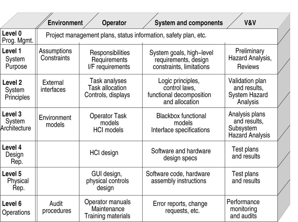
70 Intent Specifications (2) Differs in structure, not content, from other specifications Hierarchy of models Describe system from different viewpoints Traceability between models (levels) Seven levels Represent different views of system (not refinement) From different perspectives To support different types of reasoning

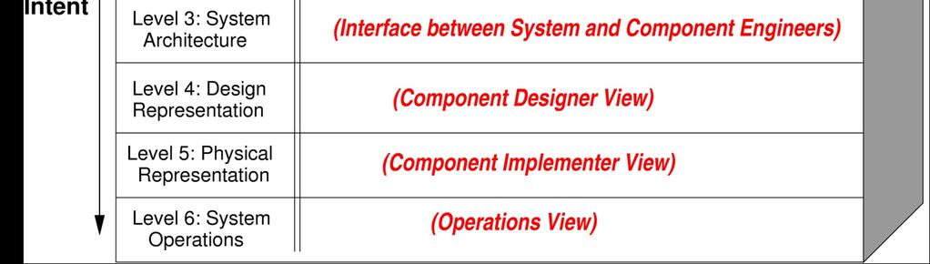
71 Intent Specifications
72
73 Level 1: System Purpose (TCAS) Introduction Historical Perspective Environment Description Environment Assumptions Attitude information is available from intruders with a minimum precision of 100 feet All aircraft have legal identification numbers Environment Constraints The behavior or interaction of non-tcas components with TCAS must not degrade the performance of the TCAS equipment
74
75

76 Create a Functional Decomposition
77 Design High-Level System Control Structure Copyright Nancy Leveson, Aug. 2006
78 Hazard List H1: Near midair collision (NMAC): An encounter for which, at the closest point of approach, the vertical separation is less than 100 feet and the horizontal separation is less than 500 feet. H2: TCAS causes controlled maneuver into ground e.g., descend command near terrain H3: TCAS causes pilot to lose control of aircraft H4: TCAS interferes with other safety-related systems e.g., interferes with ground proximity warning or ground ATC system
79 Perform STPA Identify inadequate control actions 1. A required control action is not provided or not followed 2. An incorrect or unsafe control action is provided 3. A potentially correct or inadequate control action is provided too late or too early (at the wrong time) 4. A correct control action is stopped too soon. Identify safety-related requirements and design constraints along with design decisions to eliminate or control the hazardous control actions
80
81 Example to be provided separately
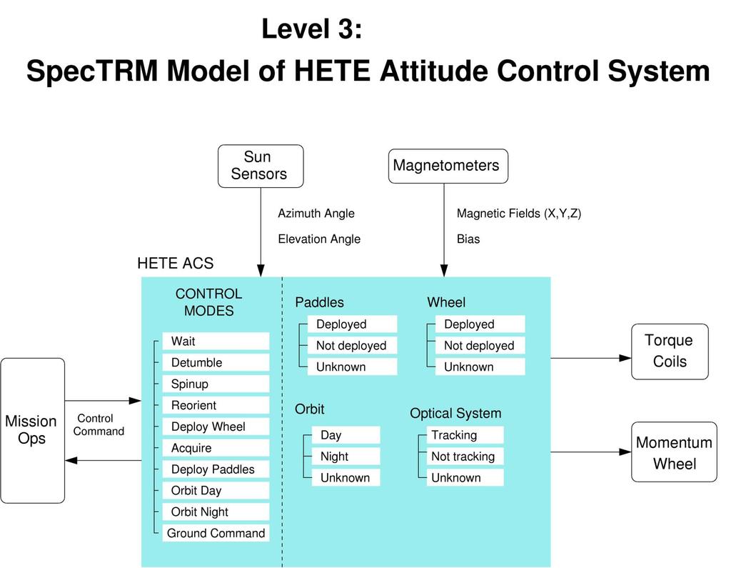
82 Example Level 2 TCAS System Design

83 Example from Level 3 Model of Collision Avoidance Logic
84
85
86 Spectrm-RL Combined requirements specification and modeling language. A state machine with a domain-specific notation on top of it Includes a task modeling language Can add other notations and visualizations of state machine Enforces or includes most of completeness criteria Supports specifying systems in terms of modes Control modes Operational modes Supervisory modes Display modes
87
88
89 Attribute Templates to Assist in Completeness
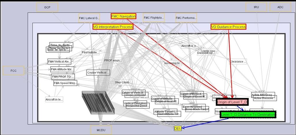
90 Visualization Tools
91

92 Templates and tools to manage hazard information

93 Editor for creating and maintaining control structure diagrams

94 Hyperlinking to more detailed views of control structure
95 Requirements Analysis

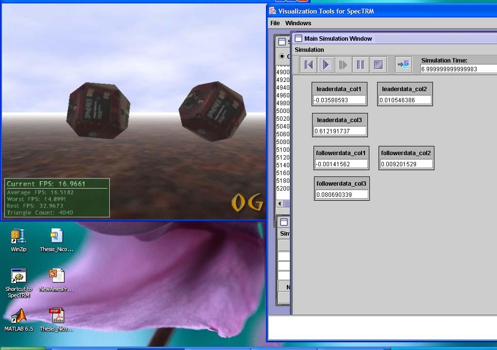
96 Black Box Model: Simulation

97 Timeline view of simulation

98 Halt on Hazardous Condition

99 Built-in static and dynamic analysis tools plus API to add others
100 Executable Specifications as Prototypes Easily changed At end, have requirements specification to use Can be reused (product families) Can be more easily reviewed than code If formal, can be analyzed Can be used in hardware-in-the-loop or operator-in-the-loop simulations. Save an enormous amount of time and money generating code for the prototypes.
101
102
103 Does it Work? Is it Practical? MDA risk assessment of inadvertent launch (technical) Architectural trade studies for the space exploration initiative (technical) Safety driven design of a NASA JPL spacecraft (technical) NASA Space Shuttle Operations (risk analysis of a new management structure) NASA Exploration Systems (risk management tradeoffs among safety, budget, schedule, performance in development of replacement for Shuttle) JAXA (Japanese Space Agency)
104 Does it Work? Is it Practical? (2) Orion (Space Shuttle Replacement) Accident analysis (spacecraft losses, bacterial contamination of water supply, aircraft collision, oil refinery explosion, train accident, chemical plant runaway reaction, etc.) Pharmaceutical safety Hospital safety (risks of outpatient surgery at Beth Israel MC) Food safety Train safety (Japan)
105 ! Safety = reliability Summary! Lots of good hardware reliability techniques! Most do not apply to software! Safety requires more than just reliability! Requirements completeness! Extended accident model (STAMP) #Treat safety as a control problem (systems or control theory rather than reliability theory) # Identify and enforce safety constraints on behavior # New types of hazard analysis and safety-driven design
106 Summary (2) Tool support needed Traceability Design rationale Reviewable and readable by anyone Unambiguous semantics Completeness analysis Executable models Visualizations Organized to assist in problem solving
Basic STPA Tutorial. John Thomas
 Basic STPA Tutorial John Thomas How is STAMP different? STAMP Model (Leveson, 2003); (Leveson, 2011) Accidents are more than a chain of events, they involve complex dynamic processes. Treat accidents as
STPA Systems Theoretic Process Analysis John Thomas and Nancy Leveson. All rights reserved.
 STPA Systems Theoretic Process Analysis 1 Agenda Quick review of hazard analysis Quick review of STAMP Intro to STPA hazard analysis 2 Hazard Analysis vs. Accident Model Dates back to Hazard Analysis Method
Systems Theoretic Process Analysis (STPA)
") Systems Theoretic Process Analysis (STPA) 1 Systems approach to safety engineering (STAMP) STAMP Model Accidents are more than a chain of events, they involve complex dynamic processes. Treat accidents
Systems Theoretic Process Analysis (STPA) 1 Systems approach to safety engineering (STAMP) STAMP Model Accidents are more than a chain of events, they involve complex dynamic processes. Treat accidents
Systems Theoretic Process Analysis (STPA)
") Systems Theoretic Process Analysis (STPA) Systems approach to safety engineering (STAMP) STAMP Model (Leveson, 2012) Accidents are more than a chain of events, they involve complex dynamic processes. Treat
Systems Theoretic Process Analysis (STPA) Systems approach to safety engineering (STAMP) STAMP Model (Leveson, 2012) Accidents are more than a chain of events, they involve complex dynamic processes. Treat
Basic STPA Exercises. Dr. John Thomas
 Basic STPA Exercises Dr. John Thomas Chemical Plant Goal: To produce and sell chemical X What (System): A chemical plant (production), How (Method): By means of a chemical reaction, a catalyst,. CATALYST
Every things under control High-Integrity Pressure Protection System (HIPPS)
") Every things under control www.adico.co info@adico.co Table Of Contents 1. Introduction... 2 2. Standards... 3 3. HIPPS vs Emergency Shut Down... 4 4. Safety Requirement Specification... 4 5. Device Integrity
Every things under control www.adico.co info@adico.co Table Of Contents 1. Introduction... 2 2. Standards... 3 3. HIPPS vs Emergency Shut Down... 4 4. Safety Requirement Specification... 4 5. Device Integrity
Real-Time & Embedded Systems
 Real-Time & Embedded Systems Agenda Safety Critical Systems Project 6 continued Safety Critical Systems Safe enough looks different at 35,000 feet. Bruce Powell Douglass The Air Force has a perfect operating
Three Approaches to Safety Engineering. Civil Aviation Nuclear Power Defense
 Three Approaches to Safety Engineering Civil Aviation Nuclear Power Defense Civil Aviation Fly-fix-fly: analysis of accidents and feedback of experience to design and operation Fault Hazard Analysis: Trace
Safety Critical Systems
 Safety Critical Systems Mostly from: Douglass, Doing Hard Time, developing Real-Time Systems with UML, Objects, Frameworks And Patterns, Addison-Wesley. ISBN 0-201-49837-5 1 Definitions channel a set of
Performing Hazard Analysis on Complex, Software- and Human-Intensive Systems
 Performing Hazard Analysis on Complex, Software- and Human-Intensive Systems J. Thomas, S.M.; Massachusetts Institute of Technology; Cambridge, Massachusetts, USA N. G. Leveson Ph.D.; Massachusetts Institute
Hazard analysis. István Majzik Budapest University of Technology and Economics Dept. of Measurement and Information Systems
 Hazard analysis István Majzik Budapest University of Technology and Economics Dept. of Measurement and Information Systems Hazard analysis Goal: Analysis of the fault effects and the evolution of hazards
Understanding safety life cycles
 Understanding safety life cycles IEC/EN 61508 is the basis for the specification, design, and operation of safety instrumented systems (SIS) Fast Forward: IEC/EN 61508 standards need to be implemented
Introducing STAMP in Road Tunnel Safety
 Introducing STAMP in Road Tunnel Safety Kostis Kazaras National Technical University of Athens, Mechanical Engineering School, Greece Contact details: kkazaras@gmail.com kkaz@central.ntua.gr Problem illustration
Modeling and Hazard Analysis Using Stpa
 Modeling and Hazard Analysis Using Stpa The MIT Faculty has made this article openly available. Please share how this access benefits you. Your story matters. Citation As Published Publisher Ishimatsu
The Safety Case. Structure of Safety Cases Safety Argument Notation
 The Safety Case Structure of Safety Cases Safety Argument Notation Budapest University of Technology and Economics Department of Measurement and Information Systems The safety case Definition (core): The
An STPA Primer. Version 1, August 2013
 An STPA Primer Version 1, August 2013 1 Table of Contents Introduction Chapter 1: What is STPA? What is an accident causality model? Traditional Chain-of-Event Causality Models What is Systems Theory?
Safety-Critical Systems
 Software Testing & Analysis (F22ST3) Safety-Critical Systems Andrew Ireland School of Mathematical and Computer Science Heriot-Watt University Edinburgh Software Testing & Analysis (F22ST3) 2 What Are
STAMP/STPA Beginner Introduction. Dr. John Thomas System Engineering Research Laboratory Massachusetts Institute of Technology
 STAMP/STPA Beginner Introduction Dr. John Thomas System Engineering Research Laboratory Massachusetts Institute of Technology Agenda Beginner Introduction What problems are we solving? How does STAMP/STPA
Failure modes and models
 Part 5: Failure modes and models Course: Dependable Computer Systems 2007, Stefan Poledna, All rights reserved part 5, page 1 Failure modes The way a system can fail is called its failure mode. Failure
Using STPA in the Design of a new Manned Spacecraft
 Using STPA in the Design of a new Manned Spacecraft Japan Aerospace Exploration Agency (JAXA) Ryo Ujiie 1 Contents Abstract Purpose JAXA s Manned Spacecraft (CRV) JAXA s Experience of STPA STPA in CRV
D-Case Modeling Guide for Target System
 D-Case Modeling Guide for Target System 1/32 Table of Contents 1 Scope...4 2 Overview of D-Case and SysML Modeling Guide...4 2.1 Background and Purpose...4 2.2 Target System of Modeling Guide...5 2.3 Constitution
The Safety Case. The safety case
 The Safety Case Structure of safety cases Safety argument notation Budapest University of Technology and Economics Department of Measurement and Information Systems The safety case Definition (core): The
Critical Systems Validation
 Critical Systems Validation Objectives To explain how system reliability can be measured and how reliability growth models can be used for reliability prediction To describe safety arguments and how these
3. Real-time operation and review of complex circuits, allowing the weighing of alternative design actions.
 PREFERRED RELIABILITY PAGE 1 OF 5 PRACTICES VOLTAGE & TEMPERATURE MARGIN TESTING Practice: Voltage and Temperature Margin Testing (VTMT) is the practice of exceeding the expected flight limits of voltage,
Missing no Interaction Using STPA for Identifying Hazardous Interactions of Automated Driving Systems
 Bitte decken Sie die schraffierte Fläche mit einem Bild ab. Please cover the shaded area with a picture. (24,4 x 11,0 cm) Missing no Interaction Using STPA for Identifying Hazardous Interactions of Automated
Basic Design for Safety Principles
 Basic Design for Safety Principles 1 Designing to Prevent Accidents Standards and codes of practice contain lessons learned from the past Standard precedence Try to eliminate hazards from the design Identify
Adaptability and Fault Tolerance
 Adaptability and Fault Tolerance Rogério de Lemos University of Kent, UK Context: self-* and dependability; Focus: adaptability and fault tolerance; State of the art; Conclusions; Rogério de Lemos ICSE
The Relationship Between Automation Complexity and Operator Error
 The Relationship Between Automation Complexity and Operator Error presented by Russell Ogle, Ph.D., P.E., CSP rogle@exponent.com (630) 274-3215 Chemical Plant Control Control physical and chemical processes
Fail Operational Controls for an Independent Metering Valve
 Group 14 - System Intergration and Safety Paper 14-3 465 Fail Operational Controls for an Independent Metering Valve Michael Rannow Eaton Corporation, 7945 Wallace Rd., Eden Prairie, MN, 55347, email:
Using what we have. Sherman Eagles SoftwareCPR.
 Using what we have Sherman Eagles SoftwareCPR seagles@softwarecpr.com 2 A question to think about Is there a difference between a medical device safety case and any non-medical device safety case? Are
Understanding the How, Why, and What of a Safety Integrity Level (SIL)
") Understanding the How, Why, and What of a Safety Integrity Level (SIL) Audio is provided via internet. Please enable your speaker (in all places) and mute your microphone. Understanding the How, Why, and
Understanding the How, Why, and What of a Safety Integrity Level (SIL) Audio is provided via internet. Please enable your speaker (in all places) and mute your microphone. Understanding the How, Why, and
Safety-critical systems: Basic definitions
 Safety-critical systems: Basic definitions Ákos Horváth Based on István Majzik s slides Dept. of Measurement and Information Systems Budapest University of Technology and Economics Department of Measurement
Safety-Critical Systems. Rikard Land
 Safety-Critical Systems Rikard Land Critical Systems Safety Critical Systems Failure may injure or kill people, damage the environment Example: nuclear and chemical plants, aircraft (Example: Weapon industry.
Software Reliability 1
 Software Reliability 1 Software Reliability What is software reliability? the probability of failure-free software operation for a specified period of time in a specified environment input sw output We
Reliability of Safety-Critical Systems Chapter 3. Failures and Failure Analysis
 Reliability of Safety-Critical Systems Chapter 3. Failures and Failure Analysis Mary Ann Lundteigen and Marvin Rausand mary.a.lundteigen@ntnu.no RAMS Group Department of Production and Quality Engineering
THE CANDU 9 DISTRffiUTED CONTROL SYSTEM DESIGN PROCESS
 THE CANDU 9 DISTRffiUTED CONTROL SYSTEM DESIGN PROCESS J.E. HARBER, M.K. KATTAN Atomic Energy of Canada Limited 2251 Speakman Drive, Mississauga, Ont., L5K 1B2 CA9900006 and M.J. MACBETH Institute for
Hazard Identification
 Hazard Identification Most important stage of Risk Assessment Process 35+ Techniques Quantitative / Qualitative Failure Modes and Effects Analysis FMEA Energy Analysis Hazard and Operability Studies HAZOP
Queue analysis for the toll station of the Öresund fixed link. Pontus Matstoms *
 Queue analysis for the toll station of the Öresund fixed link Pontus Matstoms * Abstract A new simulation model for queue and capacity analysis of a toll station is presented. The model and its software
FLIGHT CREW TRAINING NOTICE
 SAFETY REGULATION GROUP FLIGHT CREW TRAINING NOTICE 06/2009 Applicability: RETRE, TRIE, TRE, SFE, TRI, SFI Effective: Immediate AIRBORNE COLLISION AVOIDANCE SYSTEM (ACAS) TRAINING 1 The purpose of this
Session One: A Practical Approach to Managing Safety Critical Equipment and Systems in Process Plants
 Session One: A Practical Approach to Managing Safety Critical Equipment and Systems in Process Plants Tahir Rafique Lead Electrical and Instruments Engineer: Qenos Botany Site Douglas Lloyd Senior Electrical
Training Fees 3,400 US$ per participant for Public Training includes Materials/Handouts, tea/coffee breaks, refreshments & Buffet Lunch.
 Training Title DISTRIBUTED CONTROL SYSTEMS (DCS) 5 days Training Venue and Dates DISTRIBUTED CONTROL SYSTEMS (DCS) Trainings will be conducted in any of the 5 star hotels. 5 22-26 Oct. 2017 $3400 Dubai,
DeZURIK Double Block & Bleed (DBB) Knife Gate Valve Safety Manual
 Knife Gate Valve Safety Manual") Double Block & Bleed (DBB) Knife Gate Valve Safety Manual Manual D11044 September, 2015 Table of Contents 1 Introduction... 3 1.1 Terms... 3 1.2 Abbreviations... 4 1.3 Product Support... 4 1.4 Related
Double Block & Bleed (DBB) Knife Gate Valve Safety Manual Manual D11044 September, 2015 Table of Contents 1 Introduction... 3 1.1 Terms... 3 1.2 Abbreviations... 4 1.3 Product Support... 4 1.4 Related
Gravity Probe-B System Reliability Plan
 Gravity Probe-B System Reliability Plan Document #P0146 Samuel P. Pullen N. Jeremy Kasdin Gaylord Green Ben Taller Hansen Experimental Physics Labs: Gravity Probe-B Stanford University January 23, 1998
A quantitative software testing method for hardware and software integrated systems in safety critical applications
 A quantitative software testing method for hardware and software integrated systems in safety critical applications Hai ang a, Lixuan Lu* a a University of Ontario Institute of echnology, Oshawa, ON, Canada
A systematic hazard analysis and management process for the concept design phase of an autonomous vessel.
 A systematic hazard analysis and management process for the concept design phase of an autonomous vessel. Osiris A. Valdez Banda ᵃᵇ, Sirpa Kannos, Floris Goerlandt ᵃ, Piet er van Gelder ᵇ, Mart in Bergst
CT433 - Machine Safety
 Rockwell Automation On The Move May 16-17 2018 Milwaukee, WI CT433 - Machine Safety Performance Level Selection and Design Realization Jon Riemer Solution Architect Safety & Security Functional Safety
Advanced LOPA Topics
 11 Advanced LOPA Topics 11.1. Purpose The purpose of this chapter is to discuss more complex methods for using the LOPA technique. It is intended for analysts who are competent with applying the basic
(C) Anton Setzer 2003 (except for pictures) A2. Hazard Analysis
 Anton Setzer 2003 (except for pictures) A2. Hazard Analysis") A2. Hazard Analysis In the following: Presentation of analytical techniques for identifyin hazards. Non-formal, but systematic methods. Tool support for all those techniques exist. Techniques developed
A2. Hazard Analysis In the following: Presentation of analytical techniques for identifyin hazards. Non-formal, but systematic methods. Tool support for all those techniques exist. Techniques developed
Module No. # 01 Lecture No. # 6.2 HAZOP (continued)
") Health, Safety and Environmental Management in Petroleum and Offshore Engineering Prof. Srinivasan Chandrasekaran Department of Ocean Engineering Indian Institute Of Technology, Madras Module No. # 01
Health, Safety and Environmental Management in Petroleum and Offshore Engineering Prof. Srinivasan Chandrasekaran Department of Ocean Engineering Indian Institute Of Technology, Madras Module No. # 01
DeZURIK. KSV Knife Gate Valve. Safety Manual
 KSV Knife Gate Valve Safety Manual Manual D11035 August 29, 2014 Table of Contents 1 Introduction... 3 1.1 Terms... 3 1.2 Abbreviations... 4 1.3 Product Support... 4 1.4 Related Literature... 4 1.5 Reference
HAZARD ANALYSIS PROCESS FOR AUTONOMOUS VESSELS. AUTHORS: Osiris A. Valdez Banda Aalto University, Department of Applied Mechanics (Marine Technology)
") HAZARD ANALYSIS PROCESS FOR AUTONOMOUS VESSELS AUTHORS: Osiris A. Valdez Banda Aalto University, Department of Applied Mechanics (Marine Technology) Sirpa Kannos NOVIA University of Applied Science Table
HAZARD ANALYSIS PROCESS FOR AUTONOMOUS VESSELS AUTHORS: Osiris A. Valdez Banda Aalto University, Department of Applied Mechanics (Marine Technology) Sirpa Kannos NOVIA University of Applied Science Table
Solenoid Valves used in Safety Instrumented Systems
 I&M V9629R1 Solenoid Valves used in Safety Instrumented Systems Operating Manual in accordance with IEC 61508 ASCO Valves Page 1 of 7 Table of Contents 1 Introduction...3 1.1 Terms and Abbreviations...3
Ultima. X Series Gas Monitor
 Ultima X Series Gas Monitor Safety Manual SIL 2 Certified " The Ultima X Series Gas Monitor is qualified as an SIL 2 device under IEC 61508 and must be installed, used, and maintained in accordance with
Chapter 5: Methods and Philosophy of Statistical Process Control
 Chapter 5: Methods and Philosophy of Statistical Process Control Learning Outcomes After careful study of this chapter You should be able to: Understand chance and assignable causes of variation, Explain
Lecture 04 ( ) Hazard Analysis. Systeme hoher Qualität und Sicherheit Universität Bremen WS 2015/2016
 Hazard Analysis. Systeme hoher Qualität und Sicherheit Universität Bremen WS 2015/2016") Systeme hoher Qualität und Sicherheit Universität Bremen WS 2015/2016 Lecture 04 (02.11.2015) Hazard Analysis Christoph Lüth Jan Peleska Dieter Hutter Where are we? 01: Concepts of Quality 02: Legal Requirements:
Systeme hoher Qualität und Sicherheit Universität Bremen WS 2015/2016 Lecture 04 (02.11.2015) Hazard Analysis Christoph Lüth Jan Peleska Dieter Hutter Where are we? 01: Concepts of Quality 02: Legal Requirements:
DeZURIK. KGC Cast Knife Gate Valve. Safety Manual
 KGC Cast Knife Gate Valve Safety Manual Manual D11036 August 29, 2014 Table of Contents 1 Introduction... 3 1.1 Terms... 3 1.2 Abbreviations... 4 1.3 Product Support... 4 1.4 Related Literature... 4 1.5
FP15 Interface Valve. SIL Safety Manual. SIL SM.018 Rev 1. Compiled By : G. Elliott, Date: 30/10/2017. Innovative and Reliable Valve & Pump Solutions
 SIL SM.018 Rev 1 FP15 Interface Valve Compiled By : G. Elliott, Date: 30/10/2017 FP15/L1 FP15/H1 Contents Terminology Definitions......3 Acronyms & Abbreviations...4 1. Introduction...5 1.1 Scope.. 5 1.2
Purpose. Scope. Process flow OPERATING PROCEDURE 07: HAZARD LOG MANAGEMENT
 SYDNEY TRAINS SAFETY MANAGEMENT SYSTEM OPERATING PROCEDURE 07: HAZARD LOG MANAGEMENT Purpose Scope Process flow This operating procedure supports SMS-07-SP-3067 Manage Safety Change and establishes the
Safety Manual VEGAVIB series 60
 Safety Manual VEGAVIB series 60 Contactless electronic switch Document ID: 32002 Contents Contents 1 Functional safety... 3 1.1 General information... 3 1.2 Planning... 4 1.3 Adjustment instructions...
POWER Quantifying Correction Curve Uncertainty Through Empirical Methods
 Proceedings of the ASME 2014 Power Conference POWER2014 July 28-31, 2014, Baltimore, Maryland, USA POWER2014-32187 Quantifying Correction Curve Uncertainty Through Empirical Methods ABSTRACT Christopher
CHAPTER 1 INTRODUCTION TO RELIABILITY
 i CHAPTER 1 INTRODUCTION TO RELIABILITY ii CHAPTER-1 INTRODUCTION 1.1 Introduction: In the present scenario of global competition and liberalization, it is imperative that Indian industries become fully
STPA: A New Hazard Analysis Technique. (System-Theoretic Process Analysis)
") STPA: A New Hazard Analysis Technique (System-Theoretic Process Analysis) Summary: Accident Causality in STAMP Accidents occur when Control structure or control actions do not enforce safety constraints
STPA: A New Hazard Analysis Technique (System-Theoretic Process Analysis) Summary: Accident Causality in STAMP Accidents occur when Control structure or control actions do not enforce safety constraints
Reliability of Safety-Critical Systems Chapter 10. Common-Cause Failures - part 1
 Reliability of Safety-Critical Systems Chapter 10. Common-Cause Failures - part 1 Mary Ann Lundteigen and Marvin Rausand mary.a.lundteigen@ntnu.no &marvin.rausand@ntnu.no RAMS Group Department of Production
C. Mokkapati 1 A PRACTICAL RISK AND SAFETY ASSESSMENT METHODOLOGY FOR SAFETY- CRITICAL SYSTEMS
 C. Mokkapati 1 A PRACTICAL RISK AND SAFETY ASSESSMENT METHODOLOGY FOR SAFETY- CRITICAL SYSTEMS Chinnarao Mokkapati Ansaldo Signal Union Switch & Signal Inc. 1000 Technology Drive Pittsburgh, PA 15219 Abstract
Gerald D. Anderson. Education Technical Specialist
 Gerald D. Anderson Education Technical Specialist The factors which influence selection of equipment for a liquid level control loop interact significantly. Analyses of these factors and their interactions
Proof Testing A key performance indicator for designers and end users of Safety Instrumented Systems
 Proof Testing A key performance indicator for designers and end users of Safety Instrumented Systems EUR ING David Green BEng(hons) CEng MIET MInstMC RFSE Ron Bell OBE BSc CEng FIET Engineering Safety
MDEP Common Position No AP
 MDEP Validity: until net update or archiving MDEP Common Position No AP1000-01 Related to : AP1000 Working Group activities THE DESIGN AND USE OF EXPLOSIVE - ACTUATED (SQUIB) VALVES IN NUCLEAR POWER PLANTS
STICTION: THE HIDDEN MENACE
 STICTION: THE HIDDEN MENACE How to Recognize This Most Difficult Cause of Loop Cycling By Michel Ruel Reprinted with permission from Control Magazine, November 2000. (Most figures courtesy of ExperTune
Safety Manual. Process pressure transmitter IPT-1* 4 20 ma/hart. Process pressure transmitter IPT-1*
 Safety Manual Process pressure transmitter IPT-1* 4 20 ma/hart Process pressure transmitter IPT-1* Contents Contents 1 Functional safety 1.1 General information... 3 1.2 Planning... 4 1.3 Instrument parameter
PROCEDURE. April 20, TOP dated 11/1/88
 Subject: Effective Date: page 1 of 2 Initiated by: Failure Modes and Effects Analysis April 20, 1999 Supersedes: TOP 22.019 dated 11/1/88 Head, Engineering and Technical Infrastructure Approved: Director
Safety Manual VEGAVIB series 60
 Safety Manual VEGAVIB series 60 NAMUR Document ID: 32005 Contents Contents 1 Functional safety... 3 1.1 General information... 3 1.2 Planning... 4 1.3 Adjustment instructions... 6 1.4 Setup... 6 1.5 Reaction
The IEC61508 Inspection and QA Engineer s hymn sheet
 The IEC61508 Inspection and QA Engineer s hymn sheet A few key points for those inspectors and QA engineers involved with a project using the IEC61508 group of standards by the 61508 Association SAFETY
Hydraulic (Subsea) Shuttle Valves
 Shuttle Valves") SIL SM.009 0 Hydraulic (Subsea) Shuttle Valves Compiled By : G. Elliott, Date: 11/3/2014 Contents Terminology Definitions......3 Acronyms & Abbreviations..4 1. Introduction 5 1.1 Scope 5 1.2 Relevant Standards
SIL SM.009 0 Hydraulic (Subsea) Shuttle Valves Compiled By : G. Elliott, Date: 11/3/2014 Contents Terminology Definitions......3 Acronyms & Abbreviations..4 1. Introduction 5 1.1 Scope 5 1.2 Relevant Standards
New Thinking in Control Reliability
 Doug Nix, A.Sc.T. Compliance InSight Consulting Inc. New Thinking in Control Reliability Or Your Next Big Headache www.machinerysafety101.com (519) 729-5704 Control Reliability Burning Questions from the
PIG MOTION AND DYNAMICS IN COMPLEX GAS NETWORKS. Dr Aidan O Donoghue, Pipeline Research Limited, Glasgow
 PIG MOTION AND DYNAMICS IN COMPLEX GAS NETWORKS Dr Aidan O Donoghue, Pipeline Research Limited, Glasgow A model to examine pigging and inspection of gas networks with multiple pipelines, connections and
TRI LOK SAFETY MANUAL TRI LOK TRIPLE OFFSET BUTTERFLY VALVE. The High Performance Company
 TRI LOK TRI LOK TRIPLE OFFSET BUTTERFLY VALVE SAFETY MANUAL The High Performance Company Table of Contents 1.0 Introduction...1 1.1 Terms and Abbreviations... 1 1.2 Acronyms... 1 1.3 Product Support...
Reliability of Safety-Critical Systems Chapter 4. Testing and Maintenance
 Reliability of Safety-Critical Systems Chapter 4. Testing and Maintenance Mary Ann Lundteigen and Marvin Rausand mary.a.lundteigen@ntnu.no RAMS Group Department of Production and Quality Engineering NTNU
Surrogate UAV Approach and Landing Testing Improving Flight Test Efficiency and Safety
 Testing Improving Flight Test Efficiency and Safety Kevin Prosser Calspan Corporation Edwards Air Force Base, California UNITED STATES OF AMERICA kevin.prosser@calspan.com Lou Knotts Calspan Corporation
UNIVERSITY OF WATERLOO
 UNIVERSITY OF WATERLOO Department of Chemical Engineering ChE 524 Process Control Laboratory Instruction Manual January, 2001 Revised: May, 2009 1 Experiment # 2 - Double Pipe Heat Exchanger Experimental
Lab 4: Root Locus Based Control Design
 Lab 4: Root Locus Based Control Design References: Franklin, Powell and Emami-Naeini. Feedback Control of Dynamic Systems, 3 rd ed. Addison-Wesley, Massachusetts: 1994. Ogata, Katsuhiko. Modern Control
RICK FAUSEL, BUSINESS DEVELOPMENT ENGINEER TURBOMACHINERY CONTROL SYSTEM DESIGN OBJECTIVES
 RICK FAUL, BUSINESS DEVELOPMENT ENGINEER TURBOMACHINERY CONTROL SYSTEM DESIGN OBJECTIVES The primary design objective for any turbomachinery control system should be to maintain or maximize machine and
CHEMICAL ENGINEERING LABORATORY CHEG 239W. Control of a Steam-Heated Mixing Tank with a Pneumatic Process Controller
 CHEMICAL ENGINEERING LABORATORY CHEG 239W Control of a Steam-Heated Mixing Tank with a Pneumatic Process Controller Objective The experiment involves tuning a commercial process controller for temperature
CHAPTER 28 DEPENDENT FAILURE ANALYSIS CONTENTS
 Applied R&M Manual for Defence Systems Part C - Techniques CHAPTER 28 DEPENDENT FAILURE ANALYSIS CONTENTS Page 1 Introduction 2 2 Causes of Dependent Failures 3 3 Solutions 4 Issue 1 Page 1 Chapter 28
SIL explained. Understanding the use of valve actuators in SIL rated safety instrumented systems ACTUATION
 SIL explained Understanding the use of valve actuators in SIL rated safety instrumented systems The requirement for Safety Integrity Level (SIL) equipment can be complicated and confusing. In this document,
Safety Management in Multidisciplinary Systems. SSRM symposium TA University, 26 October 2011 By Boris Zaets AGENDA
 Safety Management in Multidisciplinary Systems SSRM symposium TA University, 26 October 2011 By Boris Zaets 2008, All rights reserved. No part of this material may be reproduced, in any form or by any
A study on the relation between safety analysis process and system engineering process of train control system
 A study on the relation between safety analysis process and system engineering process of train control system Abstract - In this paper, the relationship between system engineering lifecycle and safety
PERCEPTIVE ROBOT MOVING IN 3D WORLD. D.E- Okhotsimsky, A.K. Platonov USSR
 PERCEPTIVE ROBOT MOVING IN 3D WORLD D.E- Okhotsimsky, A.K. Platonov USSR Abstract. This paper reflects the state of development of multilevel control algorithms for a six-legged mobile robot. The robot
Pneumatic QEV. SIL Safety Manual SIL SM Compiled By : G. Elliott, Date: 8/19/2015. Innovative and Reliable Valve & Pump Solutions
 SIL SM.0010 1 Pneumatic QEV Compiled By : G. Elliott, Date: 8/19/2015 Contents Terminology Definitions......3 Acronyms & Abbreviations..4 1. Introduction 5 1.1 Scope 5 1.2 Relevant Standards 5 1.3 Other
SPR - Pneumatic Spool Valve
 SIL SM.008 Rev 7 SPR - Pneumatic Spool Valve Compiled By : G. Elliott, Date: 31/08/17 Contents Terminology Definitions:... 3 Acronyms & Abbreviations:... 4 1.0 Introduction... 5 1.1 Purpose & Scope...
Proposed Abstract for the 2011 Texas A&M Instrumentation Symposium for the Process Industries
 Proposed Abstract for the 2011 Texas A&M Instrumentation Symposium for the Process Industries Focus Area: Automation HMI Title: Author: Shared Field Instruments in SIS: Incidents Caused by Poor Design
Courses of Instruction: Controlling and Monitoring of Pipelines
 Courses of Instruction: Controlling and Monitoring of Pipelines Date December 2010 Dr. Peter Eschenbacher Partner Angergraben 4 85250 Altomünster Germany Tel. +49-(0)8254 / 99 69 57 Fax +49-(0)8254 / 99
Failure Modes, Effects and Diagnostic Analysis
 Failure Modes, Effects and Diagnostic Analysis Project: Solenoid Drivers KFD2-SL2-(Ex)1.LK.vvcc KFD2-SL2-(Ex)*(.B).vvcc Customer: Pepperl+Fuchs GmbH Mannheim Germany Contract No.: P+F 06/09-23 Report No.:
High Integrity Pressure Protection Systems HIPPS
 High Integrity Pressure Protection Systems HIPPS HIPPS > High Integrity Pressure Protection Systems WHAT IS A HIPPS The High Integrity Pressure Protection Systems (HIPPS) is a mechanical and electrical
RESILIENT SEATED BUTTERFLY VALVES FUNCTIONAL SAFETY MANUAL
 Per IEC 61508 and IEC 61511 Standards BRAY.COM Table of Contents 1.0 Introduction.................................................... 1 1.1 Terms and Abbreviations...........................................
FLIGHT TEST RISK ASSESSMENT THREE FLAGS METHOD
 FLIGHT TEST RISK ASSESSMENT THREE FLAGS METHOD Author: Maximilian Kleinubing BS. Field: Aeronautical Engineering, Flight Test Operations Keywords: Flight Test, Safety Assessment, Flight Test Safety Assessment
CASE STUDY. Compressed Air Control System. Industry. Application. Background. Challenge. Results. Automotive Assembly
 Compressed Air Control System Industry Automotive Assembly Application Savigent Platform and Industrial Compressed Air Systems Background This automotive assembly plant was using over 40,000 kilowatt hours
This manual provides necessary requirements for meeting the IEC or IEC functional safety standards.
 Instruction Manual Supplement Safety manual for Fisher Vee-Ball Series Purpose This safety manual provides information necessary to design, install, verify and maintain a Safety Instrumented Function (SIF)
FMEA- FA I L U R E M O D E & E F F E C T A N A LY S I S. PRESENTED BY: AJITH FRANCIS
 FMEA- FA I L U R E M O D E & E F F E C T A N A LY S I S. PRESENTED BY: AJITH FRANCIS 1 OBJECTIVES What is FMEA? Why is an FMEA important? History of FMEA Benefits of FMEA Limitations of FMEA How to conduct
IE098: Advanced Process Control for Engineers and Technicians
 IE098: Advanced Process Control for Engineers and Technicians IE098 Rev.001 CMCT COURSE OUTLINE Page 1 of 6 Training Description: Advanced Process Control and Loop Tuning and Analysis is designed to provide
Instrumented Safety Systems
 Instrumented Safety Systems Engineered Valve Systems for Control and Safety Applications HIPPS Final Elements DINO OLIVIERI Mokveld Agent AIS ISA Giornata di studio HIPPS Agenda The loop Final Elements